EP3434456A1 - Method and manufacturing machine for the production of capsules for smoking articles, in particular for filters, designed to contain a liquid to be used in the cooling of the smoke - Google Patents
Method and manufacturing machine for the production of capsules for smoking articles, in particular for filters, designed to contain a liquid to be used in the cooling of the smoke Download PDFInfo
- Publication number
- EP3434456A1 EP3434456A1 EP18185896.0A EP18185896A EP3434456A1 EP 3434456 A1 EP3434456 A1 EP 3434456A1 EP 18185896 A EP18185896 A EP 18185896A EP 3434456 A1 EP3434456 A1 EP 3434456A1
- Authority
- EP
- European Patent Office
- Prior art keywords
- plastic material
- cup
- strip
- cutting
- welding
- Prior art date
- Legal status (The legal status is an assumption and is not a legal conclusion. Google has not performed a legal analysis and makes no representation as to the accuracy of the status listed.)
- Granted
Links
Images


Classifications
-
- B—PERFORMING OPERATIONS; TRANSPORTING
- B65—CONVEYING; PACKING; STORING; HANDLING THIN OR FILAMENTARY MATERIAL
- B65B—MACHINES, APPARATUS OR DEVICES FOR, OR METHODS OF, PACKAGING ARTICLES OR MATERIALS; UNPACKING
- B65B7/00—Closing containers or receptacles after filling
- B65B7/16—Closing semi-rigid or rigid containers or receptacles not deformed by, or not taking-up shape of, contents, e.g. boxes or cartons
- B65B7/162—Closing semi-rigid or rigid containers or receptacles not deformed by, or not taking-up shape of, contents, e.g. boxes or cartons by feeding web material to securing means
- B65B7/164—Securing by heat-sealing
-
- A—HUMAN NECESSITIES
- A24—TOBACCO; CIGARS; CIGARETTES; SIMULATED SMOKING DEVICES; SMOKERS' REQUISITES
- A24D—CIGARS; CIGARETTES; TOBACCO SMOKE FILTERS; MOUTHPIECES OF CIGARS OR CIGARETTES; MANUFACTURE OF TOBACCO SMOKE FILTERS OR MOUTHPIECES
- A24D3/00—Tobacco smoke filters, e.g. filter tips or filtering inserts; Filters specially adapted for simulated smoking devices; Mouthpieces of cigars or cigarettes
- A24D3/06—Use of materials for tobacco smoke filters
- A24D3/061—Use of materials for tobacco smoke filters containing additives entrapped within capsules, sponge-like material or the like, for further release upon smoking
-
- B—PERFORMING OPERATIONS; TRANSPORTING
- B29—WORKING OF PLASTICS; WORKING OF SUBSTANCES IN A PLASTIC STATE IN GENERAL
- B29C—SHAPING OR JOINING OF PLASTICS; SHAPING OF MATERIAL IN A PLASTIC STATE, NOT OTHERWISE PROVIDED FOR; AFTER-TREATMENT OF THE SHAPED PRODUCTS, e.g. REPAIRING
- B29C69/00—Combinations of shaping techniques not provided for in a single one of main groups B29C39/00 - B29C67/00, e.g. associations of moulding and joining techniques; Apparatus therefore
-
- B—PERFORMING OPERATIONS; TRANSPORTING
- B65—CONVEYING; PACKING; STORING; HANDLING THIN OR FILAMENTARY MATERIAL
- B65B—MACHINES, APPARATUS OR DEVICES FOR, OR METHODS OF, PACKAGING ARTICLES OR MATERIALS; UNPACKING
- B65B3/00—Packaging plastic material, semiliquids, liquids or mixed solids and liquids, in individual containers or receptacles, e.g. bags, sacks, boxes, cartons, cans, or jars
- B65B3/04—Methods of, or means for, filling the material into the containers or receptacles
-
- B—PERFORMING OPERATIONS; TRANSPORTING
- B65—CONVEYING; PACKING; STORING; HANDLING THIN OR FILAMENTARY MATERIAL
- B65B—MACHINES, APPARATUS OR DEVICES FOR, OR METHODS OF, PACKAGING ARTICLES OR MATERIALS; UNPACKING
- B65B61/00—Auxiliary devices, not otherwise provided for, for operating on sheets, blanks, webs, binding material, containers or packages
- B65B61/04—Auxiliary devices, not otherwise provided for, for operating on sheets, blanks, webs, binding material, containers or packages for severing webs, or for separating joined packages
- B65B61/06—Auxiliary devices, not otherwise provided for, for operating on sheets, blanks, webs, binding material, containers or packages for severing webs, or for separating joined packages by cutting
-
- B—PERFORMING OPERATIONS; TRANSPORTING
- B29—WORKING OF PLASTICS; WORKING OF SUBSTANCES IN A PLASTIC STATE IN GENERAL
- B29C—SHAPING OR JOINING OF PLASTICS; SHAPING OF MATERIAL IN A PLASTIC STATE, NOT OTHERWISE PROVIDED FOR; AFTER-TREATMENT OF THE SHAPED PRODUCTS, e.g. REPAIRING
- B29C65/00—Joining or sealing of preformed parts, e.g. welding of plastics materials; Apparatus therefor
- B29C65/02—Joining or sealing of preformed parts, e.g. welding of plastics materials; Apparatus therefor by heating, with or without pressure
-
- B—PERFORMING OPERATIONS; TRANSPORTING
- B29—WORKING OF PLASTICS; WORKING OF SUBSTANCES IN A PLASTIC STATE IN GENERAL
- B29C—SHAPING OR JOINING OF PLASTICS; SHAPING OF MATERIAL IN A PLASTIC STATE, NOT OTHERWISE PROVIDED FOR; AFTER-TREATMENT OF THE SHAPED PRODUCTS, e.g. REPAIRING
- B29C65/00—Joining or sealing of preformed parts, e.g. welding of plastics materials; Apparatus therefor
- B29C65/78—Means for handling the parts to be joined, e.g. for making containers or hollow articles, e.g. means for handling sheets, plates, web-like materials, tubular articles, hollow articles or elements to be joined therewith; Means for discharging the joined articles from the joining apparatus
- B29C65/7841—Holding or clamping means for handling purposes
- B29C65/7847—Holding or clamping means for handling purposes using vacuum to hold at least one of the parts to be joined
-
- B—PERFORMING OPERATIONS; TRANSPORTING
- B29—WORKING OF PLASTICS; WORKING OF SUBSTANCES IN A PLASTIC STATE IN GENERAL
- B29C—SHAPING OR JOINING OF PLASTICS; SHAPING OF MATERIAL IN A PLASTIC STATE, NOT OTHERWISE PROVIDED FOR; AFTER-TREATMENT OF THE SHAPED PRODUCTS, e.g. REPAIRING
- B29C65/00—Joining or sealing of preformed parts, e.g. welding of plastics materials; Apparatus therefor
- B29C65/78—Means for handling the parts to be joined, e.g. for making containers or hollow articles, e.g. means for handling sheets, plates, web-like materials, tubular articles, hollow articles or elements to be joined therewith; Means for discharging the joined articles from the joining apparatus
- B29C65/7858—Means for handling the parts to be joined, e.g. for making containers or hollow articles, e.g. means for handling sheets, plates, web-like materials, tubular articles, hollow articles or elements to be joined therewith; Means for discharging the joined articles from the joining apparatus characterised by the feeding movement of the parts to be joined
- B29C65/7876—Means for handling the parts to be joined, e.g. for making containers or hollow articles, e.g. means for handling sheets, plates, web-like materials, tubular articles, hollow articles or elements to be joined therewith; Means for discharging the joined articles from the joining apparatus characterised by the feeding movement of the parts to be joined oscillating around an axis
-
- B—PERFORMING OPERATIONS; TRANSPORTING
- B29—WORKING OF PLASTICS; WORKING OF SUBSTANCES IN A PLASTIC STATE IN GENERAL
- B29C—SHAPING OR JOINING OF PLASTICS; SHAPING OF MATERIAL IN A PLASTIC STATE, NOT OTHERWISE PROVIDED FOR; AFTER-TREATMENT OF THE SHAPED PRODUCTS, e.g. REPAIRING
- B29C66/00—General aspects of processes or apparatus for joining preformed parts
- B29C66/01—General aspects dealing with the joint area or with the area to be joined
- B29C66/03—After-treatments in the joint area
- B29C66/032—Mechanical after-treatments
- B29C66/0326—Cutting, e.g. by using waterjets, or perforating
-
- B—PERFORMING OPERATIONS; TRANSPORTING
- B29—WORKING OF PLASTICS; WORKING OF SUBSTANCES IN A PLASTIC STATE IN GENERAL
- B29C—SHAPING OR JOINING OF PLASTICS; SHAPING OF MATERIAL IN A PLASTIC STATE, NOT OTHERWISE PROVIDED FOR; AFTER-TREATMENT OF THE SHAPED PRODUCTS, e.g. REPAIRING
- B29C66/00—General aspects of processes or apparatus for joining preformed parts
- B29C66/01—General aspects dealing with the joint area or with the area to be joined
- B29C66/05—Particular design of joint configurations
- B29C66/10—Particular design of joint configurations particular design of the joint cross-sections
- B29C66/11—Joint cross-sections comprising a single joint-segment, i.e. one of the parts to be joined comprising a single joint-segment in the joint cross-section
- B29C66/112—Single lapped joints
-
- B—PERFORMING OPERATIONS; TRANSPORTING
- B29—WORKING OF PLASTICS; WORKING OF SUBSTANCES IN A PLASTIC STATE IN GENERAL
- B29C—SHAPING OR JOINING OF PLASTICS; SHAPING OF MATERIAL IN A PLASTIC STATE, NOT OTHERWISE PROVIDED FOR; AFTER-TREATMENT OF THE SHAPED PRODUCTS, e.g. REPAIRING
- B29C66/00—General aspects of processes or apparatus for joining preformed parts
- B29C66/01—General aspects dealing with the joint area or with the area to be joined
- B29C66/05—Particular design of joint configurations
- B29C66/10—Particular design of joint configurations particular design of the joint cross-sections
- B29C66/11—Joint cross-sections comprising a single joint-segment, i.e. one of the parts to be joined comprising a single joint-segment in the joint cross-section
- B29C66/114—Single butt joints
-
- B—PERFORMING OPERATIONS; TRANSPORTING
- B29—WORKING OF PLASTICS; WORKING OF SUBSTANCES IN A PLASTIC STATE IN GENERAL
- B29C—SHAPING OR JOINING OF PLASTICS; SHAPING OF MATERIAL IN A PLASTIC STATE, NOT OTHERWISE PROVIDED FOR; AFTER-TREATMENT OF THE SHAPED PRODUCTS, e.g. REPAIRING
- B29C66/00—General aspects of processes or apparatus for joining preformed parts
- B29C66/50—General aspects of joining tubular articles; General aspects of joining long products, i.e. bars or profiled elements; General aspects of joining single elements to tubular articles, hollow articles or bars; General aspects of joining several hollow-preforms to form hollow or tubular articles
- B29C66/51—Joining tubular articles, profiled elements or bars; Joining single elements to tubular articles, hollow articles or bars; Joining several hollow-preforms to form hollow or tubular articles
- B29C66/53—Joining single elements to tubular articles, hollow articles or bars
- B29C66/534—Joining single elements to open ends of tubular or hollow articles or to the ends of bars
- B29C66/5346—Joining single elements to open ends of tubular or hollow articles or to the ends of bars said single elements being substantially flat
- B29C66/53461—Joining single elements to open ends of tubular or hollow articles or to the ends of bars said single elements being substantially flat joining substantially flat covers and/or substantially flat bottoms to open ends of container bodies
-
- B—PERFORMING OPERATIONS; TRANSPORTING
- B29—WORKING OF PLASTICS; WORKING OF SUBSTANCES IN A PLASTIC STATE IN GENERAL
- B29C—SHAPING OR JOINING OF PLASTICS; SHAPING OF MATERIAL IN A PLASTIC STATE, NOT OTHERWISE PROVIDED FOR; AFTER-TREATMENT OF THE SHAPED PRODUCTS, e.g. REPAIRING
- B29C66/00—General aspects of processes or apparatus for joining preformed parts
- B29C66/70—General aspects of processes or apparatus for joining preformed parts characterised by the composition, physical properties or the structure of the material of the parts to be joined; Joining with non-plastics material
- B29C66/71—General aspects of processes or apparatus for joining preformed parts characterised by the composition, physical properties or the structure of the material of the parts to be joined; Joining with non-plastics material characterised by the composition of the plastics material of the parts to be joined
-
- B—PERFORMING OPERATIONS; TRANSPORTING
- B29—WORKING OF PLASTICS; WORKING OF SUBSTANCES IN A PLASTIC STATE IN GENERAL
- B29C—SHAPING OR JOINING OF PLASTICS; SHAPING OF MATERIAL IN A PLASTIC STATE, NOT OTHERWISE PROVIDED FOR; AFTER-TREATMENT OF THE SHAPED PRODUCTS, e.g. REPAIRING
- B29C66/00—General aspects of processes or apparatus for joining preformed parts
- B29C66/80—General aspects of machine operations or constructions and parts thereof
- B29C66/83—General aspects of machine operations or constructions and parts thereof characterised by the movement of the joining or pressing tools
- B29C66/832—Reciprocating joining or pressing tools
- B29C66/8322—Joining or pressing tools reciprocating along one axis
-
- B—PERFORMING OPERATIONS; TRANSPORTING
- B29—WORKING OF PLASTICS; WORKING OF SUBSTANCES IN A PLASTIC STATE IN GENERAL
- B29C—SHAPING OR JOINING OF PLASTICS; SHAPING OF MATERIAL IN A PLASTIC STATE, NOT OTHERWISE PROVIDED FOR; AFTER-TREATMENT OF THE SHAPED PRODUCTS, e.g. REPAIRING
- B29C66/00—General aspects of processes or apparatus for joining preformed parts
- B29C66/80—General aspects of machine operations or constructions and parts thereof
- B29C66/84—Specific machine types or machines suitable for specific applications
- B29C66/843—Machines for making separate joints at the same time in different planes; Machines for making separate joints at the same time mounted in parallel or in series
- B29C66/8432—Machines for making separate joints at the same time mounted in parallel or in series
-
- B—PERFORMING OPERATIONS; TRANSPORTING
- B29—WORKING OF PLASTICS; WORKING OF SUBSTANCES IN A PLASTIC STATE IN GENERAL
- B29C—SHAPING OR JOINING OF PLASTICS; SHAPING OF MATERIAL IN A PLASTIC STATE, NOT OTHERWISE PROVIDED FOR; AFTER-TREATMENT OF THE SHAPED PRODUCTS, e.g. REPAIRING
- B29C66/00—General aspects of processes or apparatus for joining preformed parts
- B29C66/80—General aspects of machine operations or constructions and parts thereof
- B29C66/84—Specific machine types or machines suitable for specific applications
- B29C66/849—Packaging machines
-
- B—PERFORMING OPERATIONS; TRANSPORTING
- B29—WORKING OF PLASTICS; WORKING OF SUBSTANCES IN A PLASTIC STATE IN GENERAL
- B29L—INDEXING SCHEME ASSOCIATED WITH SUBCLASS B29C, RELATING TO PARTICULAR ARTICLES
- B29L2031/00—Other particular articles
- B29L2031/7414—Smokers'' requisites, e.g. pipe cleaners
- B29L2031/7416—Smokers'' requisites, e.g. pipe cleaners for cigars or cigarettes
Definitions
- the present invention relates to a method and to a manufacturing machine for the production of capsules for smoking articles, in particular for filters, designed to contain a liquid to be used in the cooling of the smoke.
- capsules for smoking articles has been proposed, in particular for filters, designed to contain a liquid to be used in the cooling of the smoke.
- the capsules are designed to contain water or a mixture of water and a flavour.
- said capsules comprise a cup-shaped body preferably made in one piece, for example made of a plastic material, defined by a tubular side wall and, at one end, by a bottom wall or bottom element.
- the side wall has a longitudinal axis and delimits, with the bottom element, a compartment which is adapted to contain a predetermined amount of liquid.
- the side wall can be provided with a plurality of ribs which extend in a cantilever fashion from the outer surface of the side wall, extend over the entire length of the side wall itself and are uniformly distributed around the longitudinal axis.
- the bottom wall is connected at a given height of the side wall and the connection between the bottom wall and the inner surface of the side wall is made by means of a weakened profile so as to allow, in use, the breaking under the action of a force imparted from the outside in order to pour out the liquid contained inside the compartment.
- the compartment is open at the top and is closed by a cover conveniently formed by film a or a wrap made of PET/PE.
- the capsule can also comprise a collar i.e. an annular flange, which extends in a cantilever fashion from the end of the side wall opposite the bottom wall and is arranged on a plane orthogonal to said longitudinal axis.
- capsules which comprise a cup-shaped body preferably made in one piece, for example made of a plastic material, defined by a tubular side wall and, at one end, by a bottom element having a central portion of a polygonal shape, for example hexagonal.
- the side wall has a polygonal shape in plan; in particular, the side wall has a hexagonal shape in plan, in which six side wall portions are connected to each other by means of six connecting sections.
- the connecting sections are internally weakened so as to allow, in use, to deform under the action of a force imparted from the outside by the user to pour out the liquid contained inside the compartment.
- the capsule can comprise a collar, i.e. an annular flange, which extends in a cantilever fashion from the end of the side wall opposite the bottom wall and is arranged on a plane orthogonal to said longitudinal axis.
- Capsules for smoking articles of the type described above have small dimensions, of the order of one centimetre.
- said capsules are produced by means of a manufacturing machine in which the capsules travel through a forming path via a moulding station of the cup-shaped body, a control station for the cup-shaped bodies which are obtained by moulding, a filling station with the liquid and a subsequent cutting station of the covering elements and a subsequent welding station of the covering elements to the cup-shaped bodies.
- the cutting step of the covering elements and the subsequent welding step of the covering elements to the cup-shaped bodies are extremely delicate considering the very small dimensions of the covering elements; it has, in fact, been verified that the desired productivity cannot be obtained with a satisfactory level of efficiency and without compromising the welding quality of the covering elements to the cup-shaped bodies.
- the object of the present invention is to provide a manufacturing machine for the production of capsules for smoking articles, in particular for filters, designed to contain a liquid to be used in the cooling of smoke which is free from the drawbacks of the state of the art and, at the same time, is simple and inexpensive to implement.
- Another object of the present invention is to provide a method for the production of capsules for smoking articles, in particular for filters, designed to contain a liquid to be used in the cooling of smoke which is free from the drawbacks of the state of the art and, at the same time, is simple and inexpensive to implement.
- a method and a manufacturing machine are provided for the production of capsules for smoking articles, in particular for filters, designed to contain a liquid to be used in the cooling of smoke, as claimed in the appended claims.
- number 1 denotes as a whole a capsule 1 for smoking articles, in particular for filters, designed to contain a liquid to be used in the cooling of smoke.
- the capsule 1 is designed to contain water or a mixture of water and a flavour.
- the capsule 1 comprises a cup-shaped body 2 preferably made in one piece, for example made of plastic material, defined by a tubular side wall 4 and, at one end, by a circular bottom wall 5 or bottom element.
- the cup-shaped body 2 has a shape slightly tapered towards the bottom wall 5.
- the cup-shaped body 2 has a substantially cylindrical shape.
- the side wall 4 has a longitudinal axis 3 and delimits, with the bottom wall 5, a compartment 6, which is adapted to contain a predetermined amount of liquid.
- the side wall 4 has a circular shape in plan.
- the side wall 4 is provided with a plurality of ribs (not illustrated) which extend in a cantilever fashion from the outer surface of the side wall 4, extend over the entire length of the side wall 4 and are uniformly distributed around the longitudinal axis 3.
- the bottom wall 5 is connected at a height h of the side wall 4.
- the bottom wall 5 is not arranged flush with the lower edge 9 of the side wall 4 but fits at a height h with respect to said lower edge 9.
- the connection between the bottom wall 5 and the inner surface of the side wall 4 is obtained by means of a weakened profile 5* (of reduced thickness) to allow, in use, the breakage under the action of a force imparted from the outside in order to pour out the liquid contained inside the compartment 6.
- the compartment 6 is open at the top and is closed by a cover 7 conveniently formed by a film or a wrap made of PET/PE.
- the capsule 1 comprises, furthermore, a collar defined by the upper surface of the side wall 4 to which the cover 7 is connected.
- the capsule 1 comprises a collar defined by an annular flange (not illustrated), which extends in a cantilever fashion from the end of the side wall 4 opposite the bottom wall 5 and is arranged on a plane orthogonal to said longitudinal axis 3.
- Figure 2 number 10 denotes, as a whole, a manufacturing machine for the production of the capsules 1 for smoking articles described above, which travel a forming path via a moulding station S1 of the semi-finished capsules 1 and, in particular, of the cup-shaped bodies 2, one or more check and control stations S2 for the collars and for the bottom walls 5, a transfer station S3 for transferring the cup-shaped bodies 2 into trays 9, a filling station S4 for filling the cup-shaped bodies 2 with the liquid, a welding station S5 for welding a strip 14 of plastic material to the cup-shaped bodies 2 and a cutting station S6 for cutting the strip 14 of plastic material so as to obtain the covering elements 7 welded to the respective cup-shaped bodies 2.
- the manufacturing machine 10 comprises a feeding system 11 which develops along a closed loop working path and comprises the filling station S4 with the liquid (not illustrated), the welding station S5 to weld a strip 14 of plastic material to the cup-shaped bodies 2 and the cutting station S6 of the strip 14 of plastic material to obtain the covering elements 7, welded to the respective cup-shaped bodies 2, arranged along said feeding system 11.
- the feeding system 11 is made by means of a conveyor 11 which receives the cup-shaped bodies 2 exiting the transfer station S3, and feeds them with an intermittent motion along the feeding direction A into the trays 9.
- the trays 9 have a plurality of pockets 12, each designed to receive and house a respective cup-shaped body 2; the pockets 12 are typically divided into several rows equidistant from each other and distributed over the entire available surface of the tray 9. For example, in each tray 9 ninety-six pockets 12 are obtained, divided into eight rows of twelve pockets 12 each.
- each pocket 12 is defined by a through cavity obtained in the tray 9 and is delimited by an inner surface 13 coaxial with an axis (visible in Figure 4 ).
- each tray 9 comprises at least one hole 28 (illustrated in Figure 4a ) made for centring the tray 9 at least at the welding station S5 and at the cutting station S6. Once the filling with the liquid has been completed, the trays 9 containing the cup-shaped bodies 2 are fed to the welding station S5.
- the welding station S5 comprises a welding unit 15 made through a support 16 movable in the vertical direction S provided with a plurality of striker heads 17.
- Each striker head 17 comprises a body 18 that longitudinally develops along a vertical axis and comprises an end arranged to contact/strike against a portion of the strip 14 of plastic material.
- the arrangement of the striker heads 17 reproduces the arrangement of the pockets 12 in the trays 9.
- the movable support 16 comprises ninety-six striker heads 17 divided into eight rows of twelve striker heads 17 each.
- the movable support 16 carries at least one centring pin 27 connected thereto (illustrated in Figure 4a and having a longitudinal development parallel to the development of the striker heads 17) which engages in the respective hole 28 obtained in each tray 9; in particular, the centring pin 27 is engaged in a corresponding hole 28 whenever the striker heads 17 contact the portion of the strip 14 of plastic material.
- Each striker head 17 cooperates with a respective striker element 20 for lifting the cup-shaped bodies 2 towards the striker head 17.
- the striker elements 20 are connected to a common support 21, which is also movable along the vertical direction S.
- the arrangement of the striker elements 20 reproduces the arrangement of the pockets 12 in the trays 9 and of the striker heads 17.
- the support 21 comprises ninety-six striker elements 20 divided into eight rows of twelve striker elements 20 each.
- Each striker head 17 cooperates with a respective welder 31, for example a sonotrode, so as to obtain the welding of the portion of the strip 14 of plastic material to the cup-shaped body 2, for example by means of ultrasound.
- a respective welder 31 is cooperating with a respective assembly formed by the striker head 17 and by the respective striker element 20.
- the welders 31 are carried by a common support element 30, also movable in the vertical direction S, provided with a plurality of welders 31.
- the support element 30 comprises ninety-six welders 31 divided into eight rows of twelve welders 31 each.
- the welding station S5 can provide for the striker heads 17 may provide suction.
- the welding station S5 can comprise a suction circuit made by means of a sucking pump which is connected to each striker head 17 by means of a respective suction duct so as to place each striker head 17 in communication with the sucking pump.
- the method furthermore provides for the step of activating the suction circuit so that each striker head 17 holds a corresponding portion of the strip 14 of plastic material. It is evident that the feed speed of the trays 9 on the conveyor 11 is approximately equal to the feeding speed of the strip 14 of plastic material.
- the tray 9 is again conveyed along the feeding direction A until it stops at the cutting station S6 of the covering elements 7 welded to the cup-shaped bodies 2 while a new tray 9* is fed to the welding station S5.
- a dragging device 22 is interposed, for the strip 14, designed to obtain a loop 23 of plastic material.
- the dragging device 22 is arranged close to the output of the welding unit 15.
- the dragging device 22 can comprise, for example, a pair of grippers or can preferably be of suction type.
- the dragging device 22 comprises a sucking pump (not illustrated) which is connected to a sucking head of a support element by means of a respective suction duct so as to place said sucking head in communication with the sucking pump.
- the accumulation of plastic material obtained by forming the loop 23 allows for the independence of two successive trays 9, 9* (there may also be other trays 9 interposed between them, preferably a single tray 9 is interposed between them), of which a tray 9* is intended to be subjected to the welding step in the area of the welding station S5 and a tray 9 is intended to be subjected to the cutting step in the area of the cutting station S6.
- the strip 14 of plastic material is further dragged by the dragging device 22 in the same feeding direction of the trays 9, 9* thus forming the loop 23.
- the dragging device 22 is actuated so as to lift and drag a portion of the strip 14 of plastic material and obtain the loop 23.
- the loop 23 makes it possible to create an inter-operational buffer between the welding station S5 and the cutting station S6 which makes it possible to obtain movements of the trays 9 downstream of the loop 23 with respect to the trays 9* upstream of the loop 23.
- the cutting station S6 comprises a cutting member 24 obtained by means of a support 25 provided with a plurality of cutting heads 26, preferably rotating, made as cylindrical bodies parallel to each other and provided, at one end, with a respective sharp edge.
- the arrangement of the cutting heads 25 reproduces the arrangement of the pockets 12 in the trays 9.
- the support 25 comprises ninety-six cutting heads 26 divided into eight rows of twelve cutting heads 26 each.
- the support 25 is movable between two positions along the vertical direction S.
- the support 25 is movable between a raised position and a lowered cutting position in which the strip 14 of plastic material is intercepted so as to obtain the individual covering elements 7 already welded to the respective cup-shaped bodies 2, and vice versa.
- the movement of the support 25 is directly controlled by suitable actuation means.
- the cutting station S6 comprises at least one centring pin (not illustrated) carried by the support 25 and intended to engage in the respective hole 28 of a tray 9 arranged at the cutting station S6. Therefore, the fact of obtaining the loop 23 between the trays 9, 9* makes it possible to engage the centring pins in the respective holes 28 of the trays 9, 9* as they are independent (the loop 23 allows to make possible a relative movement between the trays 9, 9*).
- the support 25 is moved along the vertical direction S downward until it reaches the lowered cutting position in which each cutting head 26 is arranged facing and near a respective semi-finished capsule 1 (and the centring pin is engaged in the hole 28 of the tray 9) ; once the circular cut on the strip 14 of plastic material is made, so as to obtain for each cutting head 26 a respective covering element 7 already welded to the respective cup-shaped bodies 2, the support 25 is again actuated and moved upwards along the vertical direction S until being arranged in the raised position. The tray 9 is then moved to the outlet by the manufacturing machine 10.
- the waste of the strip 14 of plastic material is rewound onto a reel by means of a plurality of return rollers or, alternatively, the waste of the strip 16 of plastic material it is shredded.
- the manufacturing machine 10 described up to now has various advantages. In particular, it allows the handling of small components such as the cup-shaped bodies 2 and the covering elements 7, while ensuring good performance in terms of productivity and without compromising the quality of the welding of the covering elements 7 to the respective cup-shaped bodies 2.
Landscapes
- Engineering & Computer Science (AREA)
- Mechanical Engineering (AREA)
- Chemical & Material Sciences (AREA)
- Materials Engineering (AREA)
- Lining Or Joining Of Plastics Or The Like (AREA)
Abstract
Description
- This application claims priority from Italian Patent Application No.
102017000085424 filed on July 26, 2017 - The present invention relates to a method and to a manufacturing machine for the production of capsules for smoking articles, in particular for filters, designed to contain a liquid to be used in the cooling of the smoke.
- Recently, the use of capsules for smoking articles has been proposed, in particular for filters, designed to contain a liquid to be used in the cooling of the smoke.
- In particular, the capsules are designed to contain water or a mixture of water and a flavour.
- Typically, said capsules comprise a cup-shaped body preferably made in one piece, for example made of a plastic material, defined by a tubular side wall and, at one end, by a bottom wall or bottom element. The side wall has a longitudinal axis and delimits, with the bottom element, a compartment which is adapted to contain a predetermined amount of liquid. The side wall can be provided with a plurality of ribs which extend in a cantilever fashion from the outer surface of the side wall, extend over the entire length of the side wall itself and are uniformly distributed around the longitudinal axis.
- The bottom wall is connected at a given height of the side wall and the connection between the bottom wall and the inner surface of the side wall is made by means of a weakened profile so as to allow, in use, the breaking under the action of a force imparted from the outside in order to pour out the liquid contained inside the compartment.
- The compartment is open at the top and is closed by a cover conveniently formed by film a or a wrap made of PET/PE. The capsule can also comprise a collar i.e. an annular flange, which extends in a cantilever fashion from the end of the side wall opposite the bottom wall and is arranged on a plane orthogonal to said longitudinal axis.
- Alternatively, capsules are known which comprise a cup-shaped body preferably made in one piece, for example made of a plastic material, defined by a tubular side wall and, at one end, by a bottom element having a central portion of a polygonal shape, for example hexagonal. In this case, the side wall has a polygonal shape in plan; in particular, the side wall has a hexagonal shape in plan, in which six side wall portions are connected to each other by means of six connecting sections. The connecting sections are internally weakened so as to allow, in use, to deform under the action of a force imparted from the outside by the user to pour out the liquid contained inside the compartment. Furthermore, the capsule can comprise a collar, i.e. an annular flange, which extends in a cantilever fashion from the end of the side wall opposite the bottom wall and is arranged on a plane orthogonal to said longitudinal axis.
- Capsules for smoking articles of the type described above have small dimensions, of the order of one centimetre.
- Typically, said capsules are produced by means of a manufacturing machine in which the capsules travel through a forming path via a moulding station of the cup-shaped body, a control station for the cup-shaped bodies which are obtained by moulding, a filling station with the liquid and a subsequent cutting station of the covering elements and a subsequent welding station of the covering elements to the cup-shaped bodies.
- Within the production process, the cutting step of the covering elements and the subsequent welding step of the covering elements to the cup-shaped bodies are extremely delicate considering the very small dimensions of the covering elements; it has, in fact, been verified that the desired productivity cannot be obtained with a satisfactory level of efficiency and without compromising the welding quality of the covering elements to the cup-shaped bodies.
- The object of the present invention is to provide a manufacturing machine for the production of capsules for smoking articles, in particular for filters, designed to contain a liquid to be used in the cooling of smoke which is free from the drawbacks of the state of the art and, at the same time, is simple and inexpensive to implement.
- Another object of the present invention is to provide a method for the production of capsules for smoking articles, in particular for filters, designed to contain a liquid to be used in the cooling of smoke which is free from the drawbacks of the state of the art and, at the same time, is simple and inexpensive to implement.
- According to the present invention, a method and a manufacturing machine are provided for the production of capsules for smoking articles, in particular for filters, designed to contain a liquid to be used in the cooling of smoke, as claimed in the appended claims.
- The present invention will now be described with reference to the attached drawings, which illustrate some non-limiting embodiments thereof, wherein:
-
Figures 1a to 1c respectively illustrate a perspective view, from below and in section, along the line c-c of a capsule made by the manufacturing machine which is the object of the present invention; -
Figure 2 is a block diagram that illustrates the method for the production of the capsules ofFigures 1a-1c ; -
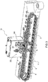
Figure 3 is a perspective view of a manufacturing machine made according to the present invention; -
Figure 4 is a front view of a welding station and of a cutting station of the manufacturing machine ofFigure 3 ; -
Figure 4A is an enlarged front view in section of the detail A ofFigure 4 , wherein some parts have been removed to better highlight others; and -
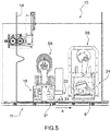
Figure 5 is a further front view of the welding station and of the cutting station ofFigure 4 . - In
Figure 1 ,number 1 denotes as a whole acapsule 1 for smoking articles, in particular for filters, designed to contain a liquid to be used in the cooling of smoke. In particular, thecapsule 1 is designed to contain water or a mixture of water and a flavour. - The
capsule 1 comprises a cup-shaped body 2 preferably made in one piece, for example made of plastic material, defined by atubular side wall 4 and, at one end, by acircular bottom wall 5 or bottom element. The cup-shaped body 2 has a shape slightly tapered towards thebottom wall 5. Alternatively, the cup-shaped body 2 has a substantially cylindrical shape. Theside wall 4 has alongitudinal axis 3 and delimits, with thebottom wall 5, acompartment 6, which is adapted to contain a predetermined amount of liquid. Theside wall 4 has a circular shape in plan. According to a preferred alternative, theside wall 4 is provided with a plurality of ribs (not illustrated) which extend in a cantilever fashion from the outer surface of theside wall 4, extend over the entire length of theside wall 4 and are uniformly distributed around thelongitudinal axis 3. - According to what is better illustrated in
Figure 1c , thebottom wall 5 is connected at a height h of theside wall 4. In other words, thebottom wall 5 is not arranged flush with thelower edge 9 of theside wall 4 but fits at a height h with respect to saidlower edge 9. - The connection between the
bottom wall 5 and the inner surface of theside wall 4 is obtained by means of a weakenedprofile 5* (of reduced thickness) to allow, in use, the breakage under the action of a force imparted from the outside in order to pour out the liquid contained inside thecompartment 6. Thecompartment 6 is open at the top and is closed by acover 7 conveniently formed by a film or a wrap made of PET/PE. Thecapsule 1 comprises, furthermore, a collar defined by the upper surface of theside wall 4 to which thecover 7 is connected. Alternatively, thecapsule 1 comprises a collar defined by an annular flange (not illustrated), which extends in a cantilever fashion from the end of theside wall 4 opposite thebottom wall 5 and is arranged on a plane orthogonal to saidlongitudinal axis 3. - In
Figure 2 number 10 denotes, as a whole, a manufacturing machine for the production of thecapsules 1 for smoking articles described above, which travel a forming path via a moulding station S1 of thesemi-finished capsules 1 and, in particular, of the cup-shaped bodies 2, one or more check and control stations S2 for the collars and for thebottom walls 5, a transfer station S3 for transferring the cup-shaped bodies 2 intotrays 9, a filling station S4 for filling the cup-shaped bodies 2 with the liquid, a welding station S5 for welding astrip 14 of plastic material to the cup-shaped bodies 2 and a cutting station S6 for cutting thestrip 14 of plastic material so as to obtain the coveringelements 7 welded to the respective cup-shaped bodies 2. - In particular, as better illustrated in
Figure 3 , themanufacturing machine 10 comprises afeeding system 11 which develops along a closed loop working path and comprises the filling station S4 with the liquid (not illustrated), the welding station S5 to weld astrip 14 of plastic material to the cup-shaped bodies 2 and the cutting station S6 of thestrip 14 of plastic material to obtain the coveringelements 7, welded to the respective cup-shaped bodies 2, arranged along saidfeeding system 11. - According to what is illustrated in
Figures 4 and5 , thefeeding system 11 is made by means of aconveyor 11 which receives the cup-shaped bodies 2 exiting the transfer station S3, and feeds them with an intermittent motion along the feeding direction A into thetrays 9. Thetrays 9 have a plurality ofpockets 12, each designed to receive and house a respective cup-shaped body 2; thepockets 12 are typically divided into several rows equidistant from each other and distributed over the entire available surface of thetray 9. For example, in eachtray 9 ninety-sixpockets 12 are obtained, divided into eight rows of twelvepockets 12 each. - According to a preferred alternative, the
pockets 12 are open at the bottom; in other words, eachpocket 12 is defined by a through cavity obtained in thetray 9 and is delimited by aninner surface 13 coaxial with an axis (visible inFigure 4 ). - Furthermore, each
tray 9 comprises at least one hole 28 (illustrated inFigure 4a ) made for centring thetray 9 at least at the welding station S5 and at the cutting station S6. Once the filling with the liquid has been completed, thetrays 9 containing the cup-shaped bodies 2 are fed to the welding station S5. - The welding station S5 comprises a
welding unit 15 made through asupport 16 movable in the vertical direction S provided with a plurality ofstriker heads 17. Eachstriker head 17 comprises abody 18 that longitudinally develops along a vertical axis and comprises an end arranged to contact/strike against a portion of thestrip 14 of plastic material. The arrangement of thestriker heads 17 reproduces the arrangement of thepockets 12 in thetrays 9. In particular, themovable support 16 comprises ninety-sixstriker heads 17 divided into eight rows of twelvestriker heads 17 each. - Moreover, the
movable support 16 carries at least onecentring pin 27 connected thereto (illustrated inFigure 4a and having a longitudinal development parallel to the development of the striker heads 17) which engages in therespective hole 28 obtained in eachtray 9; in particular, thecentring pin 27 is engaged in acorresponding hole 28 whenever the striker heads 17 contact the portion of thestrip 14 of plastic material. - Each striker head 17 cooperates with a
respective striker element 20 for lifting the cup-shaped bodies 2 towards thestriker head 17. Thestriker elements 20 are connected to acommon support 21, which is also movable along the vertical direction S. Clearly, also the arrangement of thestriker elements 20 reproduces the arrangement of thepockets 12 in thetrays 9 and of thestriker heads 17. In particular, thesupport 21 comprises ninety-sixstriker elements 20 divided into eight rows of twelvestriker elements 20 each. - Each striker head 17 cooperates with a
respective welder 31, for example a sonotrode, so as to obtain the welding of the portion of thestrip 14 of plastic material to the cup-shaped body 2, for example by means of ultrasound. Eachwelder 31 is cooperating with a respective assembly formed by thestriker head 17 and by therespective striker element 20. Thewelders 31 are carried by acommon support element 30, also movable in the vertical direction S, provided with a plurality ofwelders 31. - The arrangement of the
welders 31 thus reproduces the arrangement of thepockets 12 in thetrays 9. In particular, thesupport element 30 comprises ninety-sixwelders 31 divided into eight rows of twelvewelders 31 each. - In an alternative embodiment, not illustrated, the welding station S5 can provide for the striker heads 17 may provide suction. In said case, the welding station S5 can comprise a suction circuit made by means of a sucking pump which is connected to each
striker head 17 by means of a respective suction duct so as to place eachstriker head 17 in communication with the sucking pump. - The movement of the
movable support 16 and of thecommon support 21 is directly controlled by suitable actuation means (of a known type and not described in detail). - During the welding process, the following steps occur in succession:
- the
conveyor 11 transports thetray 9 along the feeding direction A and stops it at the welding station S5 below thewelding unit 15; - the
strip 14 of plastic material is fed with an intermittent motion in a direction parallel to the feeding direction A and is interposed between thewelding unit 15 and thetrays 9; - the
movable support 16 is moved along the vertical direction S downwards, until eachstriker head 17 is arranged facing and near a respective cup-shapedbody 2 with the interposition of thestrip 14 of plastic material (thecentring pin 27 engages in thehole 28 of thetray 9 arranged at the welding station S5) ; - the
support 21 is actuated and moved upwards along the vertical direction S so that eachstriker element 20 intercepts a respective cup-shapedbody 2 and lifts it slightly until the cup-shapedbody 2 and the corresponding portion of thestrip 14 of plastic material are arranged in substantial contact with one another (they could be placed in contact or close to each other); - the
support element 30 that carries thewelders 31 connected thereto, is moved along the vertical direction S downwards (said step can be carried out simultaneously with the downwards movement of the movable support 16); - the support elements denoted with 16 and 21 are moved (of the same length) along the vertical direction S upwards until a
welder 31 strikes against the respective portion of thestrip 14 of plastic material and the actual welding is carried out; - the
support 21 is actuated and moved downwards along the vertical direction S; similarly, themovable support 16 is actuated and moved downwards along the vertical direction S so that eachstriker head 17 accompanies (by pushing) theindividual capsules 1 inside thepockets 12 of thetray 9 which is then moved towards the subsequent cutting station S6 to cut thestrip 14 of plastic material. - In the case in which the striker heads 17 provide suction, the method furthermore provides for the step of activating the suction circuit so that each
striker head 17 holds a corresponding portion of thestrip 14 of plastic material.
It is evident that the feed speed of thetrays 9 on theconveyor 11 is approximately equal to the feeding speed of thestrip 14 of plastic material. - Once the
strip 14 of plastic material has been welded to the cup-shapedbodies 2, thetray 9 is again conveyed along the feeding direction A until it stops at the cutting station S6 of thecovering elements 7 welded to the cup-shapedbodies 2 while anew tray 9* is fed to the welding station S5. - According to what is better illustrated in
Figure 5 , between the welding station S5 and the cutting station S6 of thestrip 14 of plastic material, a draggingdevice 22 is interposed, for thestrip 14, designed to obtain aloop 23 of plastic material. In particular, the draggingdevice 22 is arranged close to the output of thewelding unit 15. - In detail, the dragging
device 22 can comprise, for example, a pair of grippers or can preferably be of suction type. In said preferred embodiment, the draggingdevice 22 comprises a sucking pump (not illustrated) which is connected to a sucking head of a support element by means of a respective suction duct so as to place said sucking head in communication with the sucking pump. - The accumulation of plastic material obtained by forming the
loop 23 allows for the independence of twosuccessive trays other trays 9 interposed between them, preferably asingle tray 9 is interposed between them), of which atray 9* is intended to be subjected to the welding step in the area of the welding station S5 and atray 9 is intended to be subjected to the cutting step in the area of the cutting station S6. - In detail, in order to obtain the
loop 23 and make the twosuccessive trays tray 9 has been arranged at the cutting station S6 and thetray 9* has been arranged at the welding station S5, thestrip 14 of plastic material is further dragged by the draggingdevice 22 in the same feeding direction of thetrays loop 23. - In use, immediately before the
tray 9* is subjected to the welding step and thetray 9 is subjected to the cutting step, the draggingdevice 22 is actuated so as to lift and drag a portion of thestrip 14 of plastic material and obtain theloop 23. Theloop 23 makes it possible to create an inter-operational buffer between the welding station S5 and the cutting station S6 which makes it possible to obtain movements of thetrays 9 downstream of theloop 23 with respect to thetrays 9* upstream of theloop 23. - According to what is better illustrated in
Figure 4 , the cutting station S6 comprises a cuttingmember 24 obtained by means of asupport 25 provided with a plurality of cutting heads 26, preferably rotating, made as cylindrical bodies parallel to each other and provided, at one end, with a respective sharp edge. The arrangement of the cutting heads 25 reproduces the arrangement of thepockets 12 in thetrays 9. In particular, thesupport 25 comprises ninety-six cutting heads 26 divided into eight rows of twelve cutting heads 26 each. - The
support 25 is movable between two positions along the vertical direction S. In particular, thesupport 25 is movable between a raised position and a lowered cutting position in which thestrip 14 of plastic material is intercepted so as to obtain theindividual covering elements 7 already welded to the respective cup-shapedbodies 2, and vice versa. The movement of thesupport 25 is directly controlled by suitable actuation means. In detail, similarly to the welding station S5, also the cutting station S6 comprises at least one centring pin (not illustrated) carried by thesupport 25 and intended to engage in therespective hole 28 of atray 9 arranged at the cutting station S6. Therefore, the fact of obtaining theloop 23 between thetrays respective holes 28 of thetrays loop 23 allows to make possible a relative movement between thetrays - In use, the
support 25 is moved along the vertical direction S downward until it reaches the lowered cutting position in which each cuttinghead 26 is arranged facing and near a respective semi-finished capsule 1 (and the centring pin is engaged in thehole 28 of the tray 9) ; once the circular cut on thestrip 14 of plastic material is made, so as to obtain for each cutting head 26 arespective covering element 7 already welded to the respective cup-shapedbodies 2, thesupport 25 is again actuated and moved upwards along the vertical direction S until being arranged in the raised position. Thetray 9 is then moved to the outlet by themanufacturing machine 10. - Upon leaving the cutting station S6, after having obtained the
covering elements 7, the waste of thestrip 14 of plastic material is rewound onto a reel by means of a plurality of return rollers or, alternatively, the waste of thestrip 16 of plastic material it is shredded. - The
manufacturing machine 10 described up to now has various advantages. In particular, it allows the handling of small components such as the cup-shapedbodies 2 and thecovering elements 7, while ensuring good performance in terms of productivity and without compromising the quality of the welding of thecovering elements 7 to the respective cup-shapedbodies 2.
Claims (12)
- A manufacturing machine (10) for the production of capsules (1) for smoking articles, in particular for filters, designed to contain a liquid to be used in the cooling of smoke; wherein each capsule (1) comprises a cup-shaped body (2) defined by a side wall (4) and, at one end, by a bottom wall (5); the side wall (4) has a longitudinal axis (3) and delimits, with the bottom wall (5), a compartment (6), which is designed to contain a predetermined amount of liquid; the capsule (1) comprising a covering element (7), which is coupled to a portion of the side wall (4) defining a collar at the end opposite the bottom wall (5); the manufacturing machine (10) comprises:a feeding system (11) that feeds the semi-finished capsules (1) along a forming path;a number of operating stations (S4, S5, S6), which are arranged along the forming path and comprise a welding station (S5) for welding a strip (14) of plastic material to a plurality of cup-shaped bodies (2); anda cutting station (S6) for cutting the strip (14) of plastic material welded to the cup-shaped bodies (2) so as to obtain the covering elements (7), wherein the cutting station (S6) is arranged downstream of the welding station (S5);the machine is characterized in that it comprises a dragging device (22) for the strip (14) of plastic material which is interposed between the welding station (S5) and the cutting station (S6) and is realized to obtain, by dragging the strip (14) of plastic material, a loop (23) of plastic material that allows two groups of semi-finished capsules (1) to be independent, wherein a first group of semi-finished capsules (1) is arranged at the welding station (S5) and a second group of semi-finished capsules (1) is arranged at the cutting station (S6).
- The machine according to claim 1, wherein the dragging device (22) is arranged close to the output of a welding unit (15) of the welding station (S5) and upstream of the cutting station (S6).
- The machine according to claim 1 or 2, wherein the dragging device (22) is of the suction type.
- The machine according to claim 3, wherein the dragging device (22) comprises a sucking pump, which is connected to a sucking head of a support element by means of a respective suction duct, so as to establish a communication between said sucking head and the sucking pump.
- The machine according to anyone of the preceding claims, wherein the cutting station (S6) comprises a cutting member (24) provided, in turn, with a first support (25), which is movable along a substantially vertical direction (S) and carries a plurality of cutting elements (26) connected thereto; the arrangement of said cutting elements (26) reproduces the arrangement of the second group of semi-finished capsules (1), so that each cutting element (26) produces a respective covering element (7) already welded to the respective cup-shaped body (2).
- The machine according to anyone of the preceding claims, wherein the semi-finished capsules (1) are housed inside respective pockets (12) of the feeding system (11); each of said pockets (12) contains a respective cup-shaped body (2) and is defined by a through cavity which is delimited by an inner surface (13).
- The machine according to claim 6, wherein the pockets (12) are obtained in trays (9), which are fed by the feeding system (11) along the forming path.
- The machine according to anyone of the preceding claims, wherein the welding station (S5) comprises a welding unit (15) that is obtained through a second support (30) which is movable along a substantially vertical direction (S) and is provided with a plurality of welders (31) so as to simultaneously weld the strip (14) of plastic material to a plurality of cup-shaped bodies (2).
- The machine according to claim 8, wherein the welding unit (15) comprises a third support (16) which is movable along a substantially vertical direction (S) and is provided with a plurality of heads (17) for striking the strip (14) of plastic material, wherein each head (17) comprises a body (18), that longitudinally develops and cooperates with a respective welder (31).
- The machine according to claim 9, wherein each head (17) cooperates with a respective striker (20) to lift the cup-shaped bodies (2); wherein the strikers (20) are connected to a fourth common support (21), which is also movable along the substantially vertical direction (S).
- A method for the production of capsules (1) for smoking articles, in particular for filters, designed to contain a liquid to be used in the cooling of smoke; wherein each capsule (1) comprises a cup-shaped body (2) defined by a side wall (4) and, at one end, by a bottom wall (5); the side wall (4) has a longitudinal axis (3) and delimits, with the bottom wall (5), a compartment (6) which is designed to contain a predetermined amount of liquid; the capsule (1) comprising a covering element (7), which is coupled to a portion of the side wall (4) defining a collar at the end opposite the bottom wall (5); the method comprises:a step of feeding the cup-shaped bodies (2) along a feeding direction (A) inside respective pockets (12) of a feeding system (11);a step of feeding a strip (14) of plastic material along a direction parallel to the feeding direction (A);a step of welding the strip (14) of plastic material to a plurality of cup-shaped bodies (2); andfollowing the welding step, a step of cutting the strip (14) of plastic material so as to obtain the covering elements (7) already welded to the cup-shaped bodies (2);the method is characterized in that it comprises a further step, by dragging the strip (14) of plastic material a loop (23) of plastic material is obtained which allows two groups of semi-finished capsules (1) to be independent, wherein a first group of semi-finished capsules (1) being intended to be subjected to the welding step and a second group of semi-finished capsules (1) being intended to be subjected to the cutting step.
- The method according to claim 11, wherein the step of obtaining the loop (23) of plastic material involves dragging the strip (14) of plastic material by means of suction.
Applications Claiming Priority (1)
| Application Number | Priority Date | Filing Date | Title |
|---|---|---|---|
| IT102017000085424A IT201700085424A1 (en) | 2017-07-26 | 2017-07-26 | Method and packaging machine for the production of capsules for smoking articles, in particular for filters, made to contain a liquid to be used for cooling the fumes |
Publications (2)
| Publication Number | Publication Date |
|---|---|
| EP3434456A1 true EP3434456A1 (en) | 2019-01-30 |
| EP3434456B1 EP3434456B1 (en) | 2021-05-05 |
Family
ID=60451086
Family Applications (1)
| Application Number | Title | Priority Date | Filing Date |
|---|---|---|---|
| EP18185896.0A Active EP3434456B1 (en) | 2017-07-26 | 2018-07-26 | Method and manufacturing machine for the production of capsules for smoking articles, in particular for filters, designed to contain a liquid to be used in the cooling of the smoke |
Country Status (2)
| Country | Link |
|---|---|
| EP (1) | EP3434456B1 (en) |
| IT (1) | IT201700085424A1 (en) |
Citations (2)
| Publication number | Priority date | Publication date | Assignee | Title |
|---|---|---|---|---|
| JPH05330503A (en) * | 1992-05-29 | 1993-12-14 | Japan Tobacco Inc | Apparatus for heat-sealing upper lid for cylindrical container |
| JP3685472B2 (en) * | 1997-02-13 | 2005-08-17 | 四国化工機株式会社 | Container sealing device |
-
2017
- 2017-07-26 IT IT102017000085424A patent/IT201700085424A1/en unknown
-
2018
- 2018-07-26 EP EP18185896.0A patent/EP3434456B1/en active Active
Patent Citations (2)
| Publication number | Priority date | Publication date | Assignee | Title |
|---|---|---|---|---|
| JPH05330503A (en) * | 1992-05-29 | 1993-12-14 | Japan Tobacco Inc | Apparatus for heat-sealing upper lid for cylindrical container |
| JP3685472B2 (en) * | 1997-02-13 | 2005-08-17 | 四国化工機株式会社 | Container sealing device |
Also Published As
| Publication number | Publication date |
|---|---|
| IT201700085424A1 (en) | 2019-01-26 |
| EP3434456B1 (en) | 2021-05-05 |
Similar Documents
| Publication | Publication Date | Title |
|---|---|---|
| EP2502831B1 (en) | Intermittent transport-type rotary bag filling and packaging apparatus | |
| CN105408211B (en) | Packaging machine and method for manufacturing capsules | |
| CN105172037A (en) | In-mold hardware and nut implanting device and feeding method thereof | |
| US3527015A (en) | Method and apparatus for filling capsules | |
| EP2035304B1 (en) | Method for singulating ophthalmic lenses | |
| EP3434456B1 (en) | Method and manufacturing machine for the production of capsules for smoking articles, in particular for filters, designed to contain a liquid to be used in the cooling of the smoke | |
| EP1553910B1 (en) | A capsule filling machine | |
| EP3424670B1 (en) | Method and manufacturing machine for the production of capsules for smoking articles, in particular for filters, designed to contain a liquid to be used in the cooling of the smoke | |
| CN104400805B (en) | A kind of Semen Arecae divides middle microtome and dicing method thereof automatically | |
| EP3434455B1 (en) | Method and manufacturing machine for the production of capsules for smoking articles, in particular for filters, designed to contain a liquid to be used in the cooling of the smoke | |
| KR20190027331A (en) | Triangle sandwich packaging machine and method of packaging triangle sandwich | |
| KR20170079386A (en) | A product moving device | |
| ITBO980276A1 (en) | ORIENTING UNIT AND BASE FEEDING UNIT FOR MEDICINAL CAPSULES I. | |
| CN106667016B (en) | Toilet brush feather planting machine automatic loading and unloading device | |
| CN105724510A (en) | Stuffed product molding machine | |
| US3176823A (en) | Transfer mechanism for tubular articles | |
| CN202011844U (en) | Industrial powder type explosive loading unit | |
| CN109303087B (en) | Vertical cutting leather mechanism | |
| EP3424669B1 (en) | Method and manufacturing machine for the production of capsules for smoking articles, in particular for filters, designed to contain a liquid to be used in the cooling of the smoke | |
| CN115673775A (en) | Full-automatic production device and processing method for copper-clad edge filter screen | |
| CN207224045U (en) | A kind of clipping broccoli dicer of rocking bar | |
| CN211033158U (en) | Prefabricated dish dress box equipment | |
| KR102011760B1 (en) | Manufacturing Apparatus of Vehicle Fuel Filter | |
| CN203919549U (en) | Commutator plastic sheath peel of mould | |
| JP3144850U (en) | Boot deburring device |
Legal Events
| Date | Code | Title | Description |
|---|---|---|---|
| PUAI | Public reference made under article 153(3) epc to a published international application that has entered the european phase |
Free format text: ORIGINAL CODE: 0009012 |
|
| STAA | Information on the status of an ep patent application or granted ep patent |
Free format text: STATUS: THE APPLICATION HAS BEEN PUBLISHED |
|
| AK | Designated contracting states |
Kind code of ref document: A1 Designated state(s): AL AT BE BG CH CY CZ DE DK EE ES FI FR GB GR HR HU IE IS IT LI LT LU LV MC MK MT NL NO PL PT RO RS SE SI SK SM TR |
|
| AX | Request for extension of the european patent |
Extension state: BA ME |
|
| STAA | Information on the status of an ep patent application or granted ep patent |
Free format text: STATUS: REQUEST FOR EXAMINATION WAS MADE |
|
| 17P | Request for examination filed |
Effective date: 20190729 |
|
| RBV | Designated contracting states (corrected) |
Designated state(s): AL AT BE BG CH CY CZ DE DK EE ES FI FR GB GR HR HU IE IS IT LI LT LU LV MC MK MT NL NO PL PT RO RS SE SI SK SM TR |
|
| GRAP | Despatch of communication of intention to grant a patent |
Free format text: ORIGINAL CODE: EPIDOSNIGR1 |
|
| STAA | Information on the status of an ep patent application or granted ep patent |
Free format text: STATUS: GRANT OF PATENT IS INTENDED |
|
| RIC1 | Information provided on ipc code assigned before grant |
Ipc: B29L 31/00 20060101ALN20201105BHEP Ipc: B29C 69/00 20060101AFI20201105BHEP Ipc: A24D 3/06 20060101ALN20201105BHEP Ipc: B65B 7/16 20060101ALI20201105BHEP Ipc: B65B 61/06 20060101ALI20201105BHEP Ipc: B65B 41/16 20060101ALI20201105BHEP Ipc: B65B 3/04 20060101ALI20201105BHEP Ipc: B29C 65/02 20060101ALN20201105BHEP Ipc: B29C 65/78 20060101ALN20201105BHEP |
|
| INTG | Intention to grant announced |
Effective date: 20201130 |
|
| GRAS | Grant fee paid |
Free format text: ORIGINAL CODE: EPIDOSNIGR3 |
|
| GRAA | (expected) grant |
Free format text: ORIGINAL CODE: 0009210 |
|
| STAA | Information on the status of an ep patent application or granted ep patent |
Free format text: STATUS: THE PATENT HAS BEEN GRANTED |
|
| AK | Designated contracting states |
Kind code of ref document: B1 Designated state(s): AL AT BE BG CH CY CZ DE DK EE ES FI FR GB GR HR HU IE IS IT LI LT LU LV MC MK MT NL NO PL PT RO RS SE SI SK SM TR |
|
| REG | Reference to a national code |
Ref country code: GB Ref legal event code: FG4D |
|
| REG | Reference to a national code |
Ref country code: CH Ref legal event code: EP |
|
| REG | Reference to a national code |
Ref country code: AT Ref legal event code: REF Ref document number: 1389279 Country of ref document: AT Kind code of ref document: T Effective date: 20210515 |
|
| REG | Reference to a national code |
Ref country code: IE Ref legal event code: FG4D |
|
| REG | Reference to a national code |
Ref country code: DE Ref legal event code: R096 Ref document number: 602018016512 Country of ref document: DE |
|
| REG | Reference to a national code |
Ref country code: LT Ref legal event code: MG9D |
|
| REG | Reference to a national code |
Ref country code: AT Ref legal event code: MK05 Ref document number: 1389279 Country of ref document: AT Kind code of ref document: T Effective date: 20210505 |
|
| PG25 | Lapsed in a contracting state [announced via postgrant information from national office to epo] |
Ref country code: LT Free format text: LAPSE BECAUSE OF FAILURE TO SUBMIT A TRANSLATION OF THE DESCRIPTION OR TO PAY THE FEE WITHIN THE PRESCRIBED TIME-LIMIT Effective date: 20210505 Ref country code: HR Free format text: LAPSE BECAUSE OF FAILURE TO SUBMIT A TRANSLATION OF THE DESCRIPTION OR TO PAY THE FEE WITHIN THE PRESCRIBED TIME-LIMIT Effective date: 20210505 Ref country code: FI Free format text: LAPSE BECAUSE OF FAILURE TO SUBMIT A TRANSLATION OF THE DESCRIPTION OR TO PAY THE FEE WITHIN THE PRESCRIBED TIME-LIMIT Effective date: 20210505 Ref country code: BG Free format text: LAPSE BECAUSE OF FAILURE TO SUBMIT A TRANSLATION OF THE DESCRIPTION OR TO PAY THE FEE WITHIN THE PRESCRIBED TIME-LIMIT Effective date: 20210805 Ref country code: AT Free format text: LAPSE BECAUSE OF FAILURE TO SUBMIT A TRANSLATION OF THE DESCRIPTION OR TO PAY THE FEE WITHIN THE PRESCRIBED TIME-LIMIT Effective date: 20210505 |
|
| PG25 | Lapsed in a contracting state [announced via postgrant information from national office to epo] |
Ref country code: SE Free format text: LAPSE BECAUSE OF FAILURE TO SUBMIT A TRANSLATION OF THE DESCRIPTION OR TO PAY THE FEE WITHIN THE PRESCRIBED TIME-LIMIT Effective date: 20210505 Ref country code: RS Free format text: LAPSE BECAUSE OF FAILURE TO SUBMIT A TRANSLATION OF THE DESCRIPTION OR TO PAY THE FEE WITHIN THE PRESCRIBED TIME-LIMIT Effective date: 20210505 Ref country code: LV Free format text: LAPSE BECAUSE OF FAILURE TO SUBMIT A TRANSLATION OF THE DESCRIPTION OR TO PAY THE FEE WITHIN THE PRESCRIBED TIME-LIMIT Effective date: 20210505 Ref country code: PL Free format text: LAPSE BECAUSE OF FAILURE TO SUBMIT A TRANSLATION OF THE DESCRIPTION OR TO PAY THE FEE WITHIN THE PRESCRIBED TIME-LIMIT Effective date: 20210505 Ref country code: NO Free format text: LAPSE BECAUSE OF FAILURE TO SUBMIT A TRANSLATION OF THE DESCRIPTION OR TO PAY THE FEE WITHIN THE PRESCRIBED TIME-LIMIT Effective date: 20210805 Ref country code: PT Free format text: LAPSE BECAUSE OF FAILURE TO SUBMIT A TRANSLATION OF THE DESCRIPTION OR TO PAY THE FEE WITHIN THE PRESCRIBED TIME-LIMIT Effective date: 20210906 Ref country code: GR Free format text: LAPSE BECAUSE OF FAILURE TO SUBMIT A TRANSLATION OF THE DESCRIPTION OR TO PAY THE FEE WITHIN THE PRESCRIBED TIME-LIMIT Effective date: 20210806 Ref country code: IS Free format text: LAPSE BECAUSE OF FAILURE TO SUBMIT A TRANSLATION OF THE DESCRIPTION OR TO PAY THE FEE WITHIN THE PRESCRIBED TIME-LIMIT Effective date: 20210905 |
|
| REG | Reference to a national code |
Ref country code: NL Ref legal event code: MP Effective date: 20210505 |
|
| PG25 | Lapsed in a contracting state [announced via postgrant information from national office to epo] |
Ref country code: NL Free format text: LAPSE BECAUSE OF FAILURE TO SUBMIT A TRANSLATION OF THE DESCRIPTION OR TO PAY THE FEE WITHIN THE PRESCRIBED TIME-LIMIT Effective date: 20210505 |
|
| PG25 | Lapsed in a contracting state [announced via postgrant information from national office to epo] |
Ref country code: EE Free format text: LAPSE BECAUSE OF FAILURE TO SUBMIT A TRANSLATION OF THE DESCRIPTION OR TO PAY THE FEE WITHIN THE PRESCRIBED TIME-LIMIT Effective date: 20210505 Ref country code: ES Free format text: LAPSE BECAUSE OF FAILURE TO SUBMIT A TRANSLATION OF THE DESCRIPTION OR TO PAY THE FEE WITHIN THE PRESCRIBED TIME-LIMIT Effective date: 20210505 Ref country code: SK Free format text: LAPSE BECAUSE OF FAILURE TO SUBMIT A TRANSLATION OF THE DESCRIPTION OR TO PAY THE FEE WITHIN THE PRESCRIBED TIME-LIMIT Effective date: 20210505 Ref country code: SM Free format text: LAPSE BECAUSE OF FAILURE TO SUBMIT A TRANSLATION OF THE DESCRIPTION OR TO PAY THE FEE WITHIN THE PRESCRIBED TIME-LIMIT Effective date: 20210505 Ref country code: RO Free format text: LAPSE BECAUSE OF FAILURE TO SUBMIT A TRANSLATION OF THE DESCRIPTION OR TO PAY THE FEE WITHIN THE PRESCRIBED TIME-LIMIT Effective date: 20210505 Ref country code: DK Free format text: LAPSE BECAUSE OF FAILURE TO SUBMIT A TRANSLATION OF THE DESCRIPTION OR TO PAY THE FEE WITHIN THE PRESCRIBED TIME-LIMIT Effective date: 20210505 Ref country code: CZ Free format text: LAPSE BECAUSE OF FAILURE TO SUBMIT A TRANSLATION OF THE DESCRIPTION OR TO PAY THE FEE WITHIN THE PRESCRIBED TIME-LIMIT Effective date: 20210505 |
|
| REG | Reference to a national code |
Ref country code: DE Ref legal event code: R097 Ref document number: 602018016512 Country of ref document: DE |
|
| REG | Reference to a national code |
Ref country code: CH Ref legal event code: PL |
|
| PLBE | No opposition filed within time limit |
Free format text: ORIGINAL CODE: 0009261 |
|
| STAA | Information on the status of an ep patent application or granted ep patent |
Free format text: STATUS: NO OPPOSITION FILED WITHIN TIME LIMIT |
|
| PG25 | Lapsed in a contracting state [announced via postgrant information from national office to epo] |
Ref country code: MC Free format text: LAPSE BECAUSE OF FAILURE TO SUBMIT A TRANSLATION OF THE DESCRIPTION OR TO PAY THE FEE WITHIN THE PRESCRIBED TIME-LIMIT Effective date: 20210505 |
|
| REG | Reference to a national code |
Ref country code: BE Ref legal event code: MM Effective date: 20210731 |
|
| 26N | No opposition filed |
Effective date: 20220208 |
|
| PG25 | Lapsed in a contracting state [announced via postgrant information from national office to epo] |
Ref country code: LI Free format text: LAPSE BECAUSE OF NON-PAYMENT OF DUE FEES Effective date: 20210731 Ref country code: CH Free format text: LAPSE BECAUSE OF NON-PAYMENT OF DUE FEES Effective date: 20210731 |
|
| PG25 | Lapsed in a contracting state [announced via postgrant information from national office to epo] |
Ref country code: IS Free format text: LAPSE BECAUSE OF FAILURE TO SUBMIT A TRANSLATION OF THE DESCRIPTION OR TO PAY THE FEE WITHIN THE PRESCRIBED TIME-LIMIT Effective date: 20210905 Ref country code: LU Free format text: LAPSE BECAUSE OF NON-PAYMENT OF DUE FEES Effective date: 20210726 Ref country code: FR Free format text: LAPSE BECAUSE OF NON-PAYMENT OF DUE FEES Effective date: 20210731 Ref country code: AL Free format text: LAPSE BECAUSE OF FAILURE TO SUBMIT A TRANSLATION OF THE DESCRIPTION OR TO PAY THE FEE WITHIN THE PRESCRIBED TIME-LIMIT Effective date: 20210505 |
|
| PG25 | Lapsed in a contracting state [announced via postgrant information from national office to epo] |
Ref country code: IT Free format text: LAPSE BECAUSE OF FAILURE TO SUBMIT A TRANSLATION OF THE DESCRIPTION OR TO PAY THE FEE WITHIN THE PRESCRIBED TIME-LIMIT Effective date: 20210505 Ref country code: IE Free format text: LAPSE BECAUSE OF NON-PAYMENT OF DUE FEES Effective date: 20210726 Ref country code: BE Free format text: LAPSE BECAUSE OF NON-PAYMENT OF DUE FEES Effective date: 20210731 |
|
| GBPC | Gb: european patent ceased through non-payment of renewal fee |
Effective date: 20220726 |
|
| PG25 | Lapsed in a contracting state [announced via postgrant information from national office to epo] |
Ref country code: GB Free format text: LAPSE BECAUSE OF NON-PAYMENT OF DUE FEES Effective date: 20220726 |
|
| PG25 | Lapsed in a contracting state [announced via postgrant information from national office to epo] |
Ref country code: CY Free format text: LAPSE BECAUSE OF FAILURE TO SUBMIT A TRANSLATION OF THE DESCRIPTION OR TO PAY THE FEE WITHIN THE PRESCRIBED TIME-LIMIT Effective date: 20210505 |
|
| PG25 | Lapsed in a contracting state [announced via postgrant information from national office to epo] |
Ref country code: HU Free format text: LAPSE BECAUSE OF FAILURE TO SUBMIT A TRANSLATION OF THE DESCRIPTION OR TO PAY THE FEE WITHIN THE PRESCRIBED TIME-LIMIT; INVALID AB INITIO Effective date: 20180726 |
|
| PG25 | Lapsed in a contracting state [announced via postgrant information from national office to epo] |
Ref country code: MK Free format text: LAPSE BECAUSE OF FAILURE TO SUBMIT A TRANSLATION OF THE DESCRIPTION OR TO PAY THE FEE WITHIN THE PRESCRIBED TIME-LIMIT Effective date: 20210505 |
|
| PG25 | Lapsed in a contracting state [announced via postgrant information from national office to epo] |
Ref country code: TR Free format text: LAPSE BECAUSE OF FAILURE TO SUBMIT A TRANSLATION OF THE DESCRIPTION OR TO PAY THE FEE WITHIN THE PRESCRIBED TIME-LIMIT Effective date: 20210505 |
|
| PG25 | Lapsed in a contracting state [announced via postgrant information from national office to epo] |
Ref country code: MT Free format text: LAPSE BECAUSE OF FAILURE TO SUBMIT A TRANSLATION OF THE DESCRIPTION OR TO PAY THE FEE WITHIN THE PRESCRIBED TIME-LIMIT Effective date: 20210505 |
|
| PGFP | Annual fee paid to national office [announced via postgrant information from national office to epo] |
Ref country code: DE Payment date: 20250729 Year of fee payment: 8 |