EP3434145A1 - Hidden hanging device and hanging furniture - Google Patents
Hidden hanging device and hanging furniture Download PDFInfo
- Publication number
- EP3434145A1 EP3434145A1 EP18183919.2A EP18183919A EP3434145A1 EP 3434145 A1 EP3434145 A1 EP 3434145A1 EP 18183919 A EP18183919 A EP 18183919A EP 3434145 A1 EP3434145 A1 EP 3434145A1
- Authority
- EP
- European Patent Office
- Prior art keywords
- height adjustment
- suspension device
- housing
- furniture
- face
- Prior art date
- Legal status (The legal status is an assumption and is not a legal conclusion. Google has not performed a legal analysis and makes no representation as to the accuracy of the status listed.)
- Granted
Links
- 239000000725 suspension Substances 0.000 claims abstract description 73
- 239000000853 adhesive Substances 0.000 claims description 10
- 230000001070 adhesive effect Effects 0.000 claims description 10
- 238000002347 injection Methods 0.000 claims description 6
- 239000007924 injection Substances 0.000 claims description 6
- 239000007788 liquid Substances 0.000 claims description 4
- 229920002430 Fibre-reinforced plastic Polymers 0.000 claims description 2
- 230000000903 blocking effect Effects 0.000 claims description 2
- 239000011151 fibre-reinforced plastic Substances 0.000 claims description 2
- 230000015572 biosynthetic process Effects 0.000 description 2
- HCHKCACWOHOZIP-UHFFFAOYSA-N Zinc Chemical compound [Zn] HCHKCACWOHOZIP-UHFFFAOYSA-N 0.000 description 1
- 238000004026 adhesive bonding Methods 0.000 description 1
- 239000011248 coating agent Substances 0.000 description 1
- 238000000576 coating method Methods 0.000 description 1
- 230000008878 coupling Effects 0.000 description 1
- 238000010168 coupling process Methods 0.000 description 1
- 238000005859 coupling reaction Methods 0.000 description 1
- 230000001419 dependent effect Effects 0.000 description 1
- 238000006073 displacement reaction Methods 0.000 description 1
- 238000005553 drilling Methods 0.000 description 1
- 239000011152 fibreglass Substances 0.000 description 1
- 238000001746 injection moulding Methods 0.000 description 1
- 238000003780 insertion Methods 0.000 description 1
- 230000037431 insertion Effects 0.000 description 1
- 238000000465 moulding Methods 0.000 description 1
- 239000011701 zinc Substances 0.000 description 1
- 229910052725 zinc Inorganic materials 0.000 description 1
Images


Classifications
-
- A—HUMAN NECESSITIES
- A47—FURNITURE; DOMESTIC ARTICLES OR APPLIANCES; COFFEE MILLS; SPICE MILLS; SUCTION CLEANERS IN GENERAL
- A47B—TABLES; DESKS; OFFICE FURNITURE; CABINETS; DRAWERS; GENERAL DETAILS OF FURNITURE
- A47B95/00—Fittings for furniture
- A47B95/008—Suspension fittings for cabinets to be hung on walls
Abstract
Eine verdeckte Aufhängevorrichtung (1) für ein an einem Gegenlager (15) aufhängbares Hängemöbel (100) weist ein in einer Möbelwand (101) festlegbares Gehäuse (2) auf, ein aus einer ersten Stirnfläche (21) des Gehäuses (2) heraus verschwenkbar angeordnetetes Tragelement (5) mit einem in das Gegenlager (15) einhängbaren Hakenteil (53), wobei das Tragelement (5) mit einem im Gehäuse (2) in einer Höhenverstellrichtung (Z) verschiebbar angeordneten Höhenverstellschlitten (3) und mit einem im Gehäuse (2) in der Höhenverstellrichtung (Z) verschiebbar angeordneten Tiefenverstellschlitten (4) gekoppelt ist, wobei das Tragelement (5) mit dem Höhenverstellschlitten (3) und mit dem Tiefenverstellschlitten (4) schwenkbar gekoppelt ist. Desweiteren wird ein Hängemöbel (100) mit einer Aufhängevorrichtung (1) beschrieben.A concealed suspension device (1) for a suspended furniture (100) which can be suspended from an abutment (15) has a housing (2) which can be fixed in a furniture wall (101), a housing pivotably arranged out of a first end surface (21) of the housing (2) Support element (5) with a hook part (53) which can be hooked into the abutment (15), wherein the support element (5) has a height adjustment slide (3) displaceably arranged in the housing (2) in a height adjustment direction (Z) and with a housing (2 ) in the height adjustment direction (Z) displaceably arranged Tiefenverstellschlitten (4) is coupled, wherein the support element (5) with the height adjustment slide (3) and with the Tiefenverstellschlitten (4) is pivotally coupled. Furthermore, a hanging furniture (100) is described with a suspension device (1).
Description
Die vorliegende Erfindung betrifft eine verdeckte Aufhängevorrichtung für ein an einem Gegenlager aufhängbares Hängemöbel gemäß dem Oberbegriff des Anspruchs 1 sowie ein Hängemöbel gemäß dem Oberbegriff des Anspruchs 16.The present invention relates to a concealed suspension device for a suspended on an abutment hanging furniture according to the preamble of
Solche Aufhängevorrichtungen dienen der Montage an der Wand hängender Möbel wie beispielsweise Hängeschränken oder Regalen. Zur Aufhängung eines solchen Möbels an einer Wand ist an der Wand ein Gegenlager, beispielsweise in Gestalt eines Wandhakens befestigt. Die Aufhängevorrichtung weist dazu ein in das Gegenlager einhängbares Tragelement auf, so dass das Möbel mit der in einer Möbelwand des Möbels befestigten Aufhängevorrichtung durch Einhängen des Tragelements in das Gegenlager an der Wand befestigt werden kann.Such hangers are used for mounting on the wall hanging furniture such as wall cabinets or shelves. To mount such a piece of furniture on a wall, an abutment, for example in the form of a wall hook, is fastened to the wall. For this purpose, the suspension device has a support element which can be suspended in the abutment, so that the furniture can be fastened to the wall with the suspension device fastened in a furniture wall of the furniture by hanging the support element into the abutment.
Die üblichen Aufhängevorrichtungen sind dabei sichtbar an der Möbelwand des Möbels befestigt. Wünschenswert ist es, eine solche Aufhängevorrichtung verdeckt anzuordnen, so dass diese für den Betrachter nicht sichtbar ist.The usual suspension devices are visible attached to the furniture wall of the furniture. It is desirable to arrange such a suspension hidden, so that it is not visible to the viewer.
Eine verdeckt in einer Möbelwand angeordnete Aufhängevorrichtung ist beispielsweise aus der
Als Höhenverstellrichtung wird hier eine vertikale Verstellrichtung verstanden. Als Tiefenverstellrichtung wird eine Richtung verstanden, die einer Normalen zu der Wand, an der das Möbel aufgehängt werden soll, entspricht.As a height adjustment direction is understood here a vertical adjustment. The depth adjustment direction is understood to mean a direction that corresponds to a normal to the wall on which the furniture is to be hung.
Um die Verstellung des Tragelements bei dieser Aufhängevorrichtung vorzunehmen, sind Montagelöcher an der Seiteninnenwand der Möbelwand notwendig. Darüber hinaus kann das Tragelement dieser Aufhängevorrichtung nur vertikal oder in der Tiefe verschoben werden.To make the adjustment of the support member in this suspension, mounting holes on the side inner wall of the furniture wall are necessary. In addition, the support element of this suspension can only be moved vertically or in depth.
Aufgabe der vorliegenden Erfindung ist es, eine Aufhängevorrichtung sowie ein Hängemöbel bereitzustellen, mit dem die Montage des Hängemöbels an der Wand nochmals erleichtert wird.Object of the present invention is to provide a suspension and a hanging furniture, with the mounting of the hanging furniture on the wall is further facilitated.
Diese Aufgabe wird durch eine verdeckte Aufhängevorrichtung mit den Merkmalen des Anspruchs 1 sowie durch ein Hängemöbel mit den Merkmalen des Anspruchs 16 gelöst.This object is achieved by a concealed suspension device with the features of
Die erfindungsgemäße Aufhängevorrichtung weist ein in einer Möbelwand festlegbares Gehäuse auf sowie ein aus einer ersten Stirnfläche des Gehäuses heraus bewegbares Tragelement mit einem in ein Gegenlager einhängbaren Hakenteil. Das Tragelement ist mit einem im Gehäuse in einer Höhenverstellrichtung verschiebbar angeordneten Höhenverstellschlitten und mit einem im Gehäuse in der Höhenverstellrichtung verschiebbar angeordneten Tiefenverstellschlitten gekoppelt. Das Tragelement ist dabei mit dem Höhenverstellschlitten und mit dem Tiefenverstellschlitten schwenkbar gekoppelt.The suspension device according to the invention has a fixable in a furniture wall housing and a movable out of a first end face of the housing support member with a hook in a counter-bearing hook part. The support element is coupled to a height adjustment slide displaceably arranged in the housing in a height adjustment direction and to a depth adjustment slide displaceably arranged in the housing in the height adjustment direction. The support member is pivotally coupled to the height adjustment slide and the depth adjustment slide.
Mit einer solchermaßen ausgebildeten Aufhängevorrichtung ist eine einfach durchzuführende Montage des Hängemöbels an einem an einer Wand angeordneten Gegenlager ermöglicht.With such a trained suspension a simple to be carried out mounting of the hanging furniture on a wall arranged on an abutment is possible.
Das erfindungsgemäße Hängemöbel weist wenigstens eine Möbelwand, vorzugsweise Möbelseitenwand, mit einer zu einer Stirnseite hin offenen, in einen Hohlraum mündenden Aussparung auf, wobei in dem Hohlraum eine Aufhängevorrichtung aufgenommen ist, wobei die Aufhängevorrichtung wie oben beschrieben ausgebildet ist. Die Stirnseite einer Möbelwand wird durch eine Schmalseite gebildet. Die Schmalseite kann mit einer Schmalseitenbeschichtung oder einem Kantenumleimer versehen sein. Somit weist eine Möbelwand wenigstens drei Stirnseiten und in der Regel vier Stirnseiten auf.The hanging furniture according to the invention has at least one furniture wall, preferably furniture side wall, with an open towards a front side, opening into a cavity recess, wherein in the cavity a suspension device is received, wherein the suspension device is formed as described above. The front of a furniture wall is formed by a narrow side. The narrow side can be provided with a narrow-side coating or an edge trimmer. Thus, a furniture wall at least three end faces and usually four end faces.
Vorteilhafte Ausführungsvarianten sind Gegenstand der Unteransprüche.Advantageous embodiments are the subject of the dependent claims.
Gemäß einer Ausführungsvariante sind in dem Gehäuse ein relativ zum Gehäuse ortsfestes, mit dem Höhenverstellschlitten gekoppeltes Höhenverstellelement und ein relativ zum Höhenverstellschlitten ortsfestes, mit dem Tiefenverstellschlitten gekoppeltes Tiefenverstellelement aufgenommen.According to one embodiment, a height adjustment element which is stationary relative to the housing and is coupled to the height adjustment slide, and a depth adjustment element which is stationary relative to the height adjustment slide and is coupled to the depth adjustment slide, are accommodated in the housing.
Dies ermöglicht eine Tiefenverstellung des Tragelements in jeder beliebigen Höhenposition des Tragelements.This allows a depth adjustment of the support element in any height position of the support element.
Nach einer weiteren vorteilhaften Ausführungsvariante sind das Höhenverstellelement und das Tiefenverstellelement als Verstellschrauben, insbesondere baugleiche Verstellschrauben ausgebildet.According to a further advantageous embodiment variant, the height adjustment element and the depth adjustment element are designed as adjusting screws, in particular identical adjusting screws.
Nach einer weiteren Ausführungsvariante ist eine obere und/oder eine untere Öffnung des Gehäuses durch eine Endkappe verschlossen, was zum einen einen Schutz der im Gehäuse angeordneten Mechanik ermöglicht und zum zweiten ermöglicht, das Gehäuse gemäß einer weiteren bevorzugten Ausführungsvariante als einstückiges Strangpressprofil oder faserverstärktes Kunststoffbauteil ausgebildet ist..According to a further embodiment variant, an upper and / or a lower opening of the housing is closed by an end cap, which on the one hand enables protection of the mechanism arranged in the housing and allows for the second, the housing according to another preferred embodiment designed as a one-piece extruded profile or fiber-reinforced plastic component is ..
Nach einer weiteren Ausführungsvariante weist die obere Endkappe zwei Durchgangsbohrungen auf, durch die mit einem Werkzeug das Höhenverstellelement und das Tiefenverstellelement erreichbar sind.According to a further embodiment, the upper end cap on two through holes through which the height adjustment element and the Tiefenverstellelement can be reached with a tool.
Dies ermöglicht einen Zugang zu dem Höhenverstellelement und dem Tiefenverstellelement durch Montagebohrungen in einer Oberseite der Möbelwand, die insbesondere bei Hängemöbeln, deren Oberkante in einer Höhe von zwei Metern oder mehr über dem Fußboden eines Raumes, in dem das Hängemöbel aufgehängt wird, für den Betrachter nicht sichtbar sind.This allows access to the Höhenverstellelement and Tiefenverstellelement by mounting holes in a top of the furniture wall, especially for suspended furniture, the top edge at a height of two meters or more above the floor of a room in which the hanging furniture is suspended, not for the viewer are visible.
Zur Lagerung des bevorzugt nach Art einer Bundschraube ausgebildeten Höhenverstellelements ist Kopf der Bundschraube formschlüssig in einer Ausnehmung der oberen Endkappe gehalten, so dass die Bundschraube in Höhenverstellrichtung ortsfest in der Endkappe gehalten ist.For storage of preferably designed in the manner of a collar screw height adjustment head of the collar screw is positively held in a recess of the upper end cap, so that the collar screw is held in the height adjustment direction fixed in the end cap.
Zur Verschwenkung des Tragelements ist gemäß einer bevorzugten Ausführungsvariante ein Schwenklager, an dem das Tragelement an dem Höhenverstellschlitten schwenkbar gelagert ist, als in einer Drehzapfenaufnahme des Höhenverstellschlittens und in einer Drehzapfenaufnahme des Tragelements gelagerter Drehzapfen ausgebildet.For pivoting the support element, according to a preferred embodiment, a pivot bearing, on which the support element is pivotally mounted on the height adjustment slide, formed as in a pivot receptacle of the height adjustment slide and in a pivot receptacle of the support member mounted pivot.
Das Schwenklager, an dem das Tragelement an dem Tiefenverstellschlitten schwenkbar gelagert ist, ist bevorzugt an dem Tiefenverstellschlitten integral angeformt.The pivot bearing, on which the support element is pivotably mounted on the depth adjustment slide, is preferably integrally formed on the depth adjustment slide.
Denkbar ist auch die integrale Anformung eines Schwenklagers am Höhenverstellschlitten bzw. die Anordnung eines Drehzapfens in einer entsprechenden Drehzapfenaufnahme des Tiefenverstellschlittens.Also conceivable is the integral molding of a pivot bearing on the height adjustment slide or the arrangement of a pivot in a corresponding pivot receptacle of Tiefenverstellschlittens.
Zur einfachen Ausbildung eines Gewindes in dem Höhenverstellschlitten, der bevorzugt aus Zink-Druckguss oder glasfaserverstärkten Kunststoff, gefertigt ist, ist in dem Höhenverstellschlitten gemäß einer weiteren bevorzugten Ausführungsvariante eine mit einem Innengewinde versehene Mutter verdrehfest aufgenommen, in die das als Verstellschraube ausgebildete Höhenverstellelement eingeschraubt ist.For easy formation of a thread in the height adjustment slide, which is preferably made of zinc die-cast or fiberglass reinforced plastic, a nut provided with an internal thread is rotationally received in the height adjustment slide according to a further preferred embodiment, in which the height adjustment element designed as an adjusting screw is screwed.
Zur Verstellung des Tiefenverstellschlittens in Höhenverstellrichtung weist ein Grundkörper des Tiefenverstellschlittens bevorzugt eine sich in Höhenverstellrichtung erstreckende Gewindebohrung auf, in die das als Verstellschraube ausgebildete Tiefenverstellelement eingeschraubt ist.In order to adjust the depth adjustment slide in height adjustment direction, a base body of the depth adjustment slide preferably has a threaded bore extending in height adjustment direction, into which the depth adjustment element designed as an adjusting screw is screwed.
Nach einer weiteren bevorzugten Ausführungsvariante ist an dem Höhenverstellschlitten ein Aushängesicherungselement angeordnet. Das Aushängesicherungselement ist dabei bevorzugt als Blattfeder ausgebildet.According to a further preferred embodiment variant, a safety catch element is arranged on the height adjustment slide. The Aushängegesicherung element is preferably formed as a leaf spring.
Eine solche Aushängesicherung zeichnet sich dadurch aus, dass diese sofort nach dem Einhängen des Hakenteils des Tragelements in das Gegenlager wirksam ist.Such a safety catch is characterized in that it is effective immediately after hanging the hook part of the support member in the anvil.
Gemäß einer vorteilhaften Ausführungsvariante des erfindungsgemäßen Hängemöbels steht von einer der ersten Stirnfläche des Gehäuses der Aufhängevorrichtung abgewandten zweiten Stirnfläche wenigstens ein Haltelement vor, das in einer sich an den Hohlraum anschließenden Ausnehmung der Möbelwand verklebt ist.According to an advantageous embodiment variant of the hanging furniture according to the invention, at least one holding element protrudes from a second end face remote from the first end face of the housing of the suspension device, which is glued into a recess of the furniture wall adjoining the cavity.
Das Halteelement kann dabei in Gestalt mehrerer Zapfen ausgebildet sein, die in sich an den Hohlraum anschließenden Zapfenausnehmungen verklebt sind.The holding element may be formed in the form of a plurality of pins which are glued into adjoining the cavity pin recesses.
Denkbar ist auch die Ausbildung eines solchen Haltelements in Gestalt eines Profilstücks, das vorzugsweise in einer Profilnut in der zweiten Stirnfläche des Gehäuses eingehängt oder integral angeformt ist und in einer entsprechenden sich an den Hohlraum anschließenden Profilausnehmung verklebt ist.Also conceivable is the formation of such a holding element in the form of a profile piece, which is preferably suspended in a profile groove in the second end face of the housing or integrally formed and is glued in a corresponding adjoining the cavity profile recess.
Nach einer nochmals weiteren Ausführungsvariante des Hängemöbels schließt sich an die obere Endkappe ein Anschlussstück mit mindestens einer Durchgangsbohrung mit seitlichen Austrittsöffnungen an, durch die ein Flüssigklebemittel in an wenigstens einer der Seitenflächen des Gehäuses und/oder wenigstens einer an diesen anliegenden, den Hohlraum begrenzenden Innenflächen der Möbelwand angeformte Kleberkammer einspritzbar ist.According to yet another embodiment variant of the hanging furniture, the upper end cap is adjoined by a connecting piece with at least one through-hole with lateral outlet openings, through which a liquid adhesive is applied to at least one of the side surfaces of the housing and / or at least one inner surface of the housing adjoining the cavity Furniture wall molded adhesive chamber can be injected.
Dadurch ist ebenfalls eine zuverlässige Festlegung des Gehäuses der Aufhängevorrichtung in der Möbelwand sichergestellt.As a result, a reliable fixing of the housing of the suspension in the furniture wall is also ensured.
Nachfolgend werden bevorzugte Ausführungsbeispiele anhand der beiliegenden Zeichnungen näher erläutert. Es zeigen:
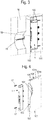
Figur 1- eine perspektivische Darstellung eines an einer Wand aufgehängten Hängemöbels,
Figur 2- eine perspektivische Darstellung des an der Wand aufgehängten Hängemöbels mit teilaufgerissener Möbelwand zur Darstellung der in der Möbelwand angeordneten Aufhängevorrichtung,
Figur 3- eine Detailansicht der in
Figur 2 Figur 4- eine perspektivische Ansicht einer Möbelwand mit darin vorgesehenem Hohlraum zur Aufnahme der Aufhängevorrichtung,
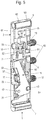
Figur 5- eine perspektivische Ansicht einer Ausführungsvariante der Aufhängevorrichtung mit teilweise weggeschnittener Gehäusewand,
Figur 6- eine perspektivische Explosionsdarstellung der Aufhängevorrichtung aus
Figur 5 Figur 7- eine schematische Draufsicht auf eine Möbelwand und eine Aufhängevorrichtung und eines Spritzwerkzeugs zur Darstellung der Montage der Aufhängevorrichtung an der Möbelwand,
Figur 8- eine Draufsicht auf die Möbelwand mit eingesetzter Aufhängevorrichtung vor der zusätzlichen Fixierung mit Sicherungsschrauben,
Figur 9- eine perspektivische Darstellung der teilaufgerissenen Möbelwand mit darin aufgenommener Aufhängevorrichtung mit alternativer Anordnung der Sicherungsschrauben,
Figur 10- eine perspektivische Ansicht einer Möbelwand und einer Aufhängevorrichtung mit als Profilstück ausgebildetem Halteelement zur Fixierung der Aufhängevorrichtung an der Möbelwand,
- Figuren 11a und b
- perspektivische Darstellungen einer weiteren Möglichkeit zur Fixierung der Aufhängevorrichtung in der Möbelwand durch Verkleben,
- Figuren 12a bis d
- Frontansichten zur Darstellung der Montage des Hängemöbels an der Wand,
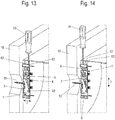
Figuren 13 und 14- perspektivische Darstellungen des an der Wand aufgehängten Hängemöbels zur Darstellung der Tiefenverstellung (
Figur 13 ) und Höhenverstellung (Figur 14 ).
- FIG. 1
- a perspective view of a suspended on a wall hanging furniture,
- FIG. 2
- a perspective view of the suspended on the wall hanging furniture with teilaufgerissener furniture wall for displaying the arranged in the furniture wall suspension device,
- FIG. 3
- a detailed view of in
FIG. 2 shown arrangement, - FIG. 4
- a perspective view of a furniture wall with therein cavity for receiving the suspension device,
- FIG. 5
- a perspective view of an embodiment of the suspension device with partially cut housing wall,
- FIG. 6
- an exploded perspective view of the suspension
FIG. 5 . - FIG. 7
- a schematic plan view of a furniture wall and a suspension device and an injection mold for illustrating the mounting of the suspension device on the furniture wall,
- FIG. 8
- a top view of the furniture wall with inserted suspension device before the additional fixation with locking screws,
- FIG. 9
- 3 is a perspective view of the partially opened furniture wall with a suspension device accommodated therein with an alternative arrangement of the securing screws;
- FIG. 10
- a perspective view of a furniture wall and a suspension device designed as a profile piece holding element for fixing the suspension device to the furniture wall,
- FIGS. 11a and b
- perspective views of another way to fix the suspension in the furniture wall by gluing,
- FIGS. 12a to d
- Front views showing the mounting of the hanging furniture on the wall,
- FIGS. 13 and 14
- perspective views of the suspended hanging on the wall hanging furniture to show the depth adjustment (
FIG. 13 ) and height adjustment (FIG. 14 ).
In der nachfolgenden Figurenbeschreibung beziehen sich Begriffe wie oben, unten, links, rechts, vorne, hinten usw. ausschließlich auf die in den jeweiligen Figuren gewählte beispielhafte Darstellung und Position der Aufhängevorrichtung, des Hängemöbels, der Möbelwand, des Tragelements, des Höhenverstellschlittens, des Tiefenverstellschlittens, des Gehäuses und dergleichen. Diese Begriffe sind nicht einschränkend zu verstehen, d.h., durch verschiedene Arbeitsstellungen oder die spiegelsymmetrische Auslegung oder dergleichen können sich diese Bezüge ändern.In the following description of the figures, terms such as above, below, left, right, front, back, etc. refer exclusively to the exemplary representation and position of the suspension device, the hanging furniture, the furniture wall, the support element, the height adjustment slide, the depth adjustment slide selected in the respective figures , the housing and the like. These terms are not meant to be limiting, that is to say, by different working positions or the mirror-symmetrical design or the like, these references may change.
In den
Das Hängemöbel 100 weist zwei Möbelwände 101 auf, in denen jeweils eine Aufhängevorrichtung 1 in einen dafür vorgesehenen Hohlraum 103 aufgenommen ist. Der Hohlraum 103 ist dabei zu einer Stirnseite 102 der Möbelwand 101 hin offen.The hanging
Die Aufhängevorrichtung 1 weist zur Aufhängung des Hängemöbels 100 an einer Wand 16 ein Tragelement 5 mit einem Hakenteil 53 auf, das in ein Gegenlager 15 einhängbar ist. Das Gegenlager 15 ist dabei beispielsweise als in die Wand 16 eingeschraubter Wandhaken ausgebildet.The
Denkbar sind auch andere Ausgestaltungen eines solchen Gegenlagers 15, beispielsweise in Gestalt einer in die Wand eingelassenen Schiene mit vorstehenden Hakenelementen oder dergleichen.Also conceivable are other embodiments of such an
Wie in den
Denkbar ist auch eine Ausgestaltung der Möbelwand mit zwei Möbelwandhälften 101a und 10b mit entsprechend geformten hälftigen Aussparungen, die zusammen den Hohlraum 103 bilden und nach dem Einsetzen der Aufhängevorrichtung 1 miteinander verklebt werden.Also conceivable is an embodiment of the furniture wall with two
Wie in
Zur Fixierung der Aufhängevorrichtung 1 in der Möbelwand 101 sind des Weiteren auf einer im eingebauten Zustand der Stirnseite 102 abgewandten Rückseite eines Gehäuses 2 der Aufhängevorrichtung 1 Haltelemente in Form mehrerer Zapfen 12 an dem Gehäuse 2 der Aufhängevorrichtung 1 befestigt, die in entsprechenden Zapfenaufnahmen 104 der Möbelwand 101 aufgenommen sind und dort mit der Möbelwand 101 verklebt werden.To fix the
Zur zusätzlichen oder alternativen Sicherung sind in dem Gehäuse 2 Aufnahmen für Sicherungsschrauben 17 vorgesehen, die durch das Gehäuse 2 hindurch in die Möbelwand 101 oder in ein weiteres in der Möbelwand integriertes Beschlagsteilgehäuse , beispielsweise eines Klappenbeschlags, eingeschraubt sind.For additional or
Alternativ zur Anordnung solcher Zapfen 12 ist es auch denkbar, auf der Rückseite des Gehäuses 2 ein Profilstück 18 anzubringen, das in einer entsprechend geformten Profilausnehmung 106 der Möbelwand 101 eingelegt und verklebt ist, wie es in
In den
Diese Ankopplung ist hier derart ausgebildet, dass das Tragelement 5 mit dem Höhenverstellschlitten 3 und dem Tiefenverstellschlitten 4 schwenkbar gekoppelt ist. Dazu ist ein hier als Drehzapfen ausgebildetes Schwenklager 44 in einer Drehzapfenaufnahme 55 des Tragelements 5 und in einer Drehzapfenaufnahme 35 des Höhenverstellschlittens 3 gelagert. Damit ist das Tragelement 5 zusammen mit dem Höhenverstellschlitten in Höhenverstellrichtung Z justierbar.This coupling is designed here such that the
Das Tragelement 5 ist insbesondere U-förmig ausgebildet und weist zwei gegenüberliegende Schenkel 51 und 52 auf. Das Tragelement umgreift mit den Schenkeln 51 und 52 den Höhenverstellschlitten 3. Zudem weist das Tragelement 5 zwischen dem Hakenteil 53 und dem Schwenklager 44 eine Ausnehmung 57 auf, durch welche sich das Gegenlager 15 und das an dem Höhenverstellschlitten 3 angeordnete Aushängesicherungselement 11 erstreckt.The
Um das Hakenteil 53 des Tragelements 5 aus einer in
An dem Tiefenverstellschlitten 4 ist, wie in den
Dementsprechend bewirkt eine Bewegung des Schwenklagers 53 des Tiefenverstellschlittens 4 nach oben ein Herausschwenken des Hakenteils 53 des Tragelements 5 aus dem Gehäuse 2 heraus.Accordingly, a movement of the pivot bearing 53 of the
Um ein Herein- und Herausschwenken des Tragelements 5 in jeder Höhenposition des Tragelements 5 zu gewährleisten, ist der Höhenverstellschlitten 3 über ein im Gehäuse 2 relativ zu diesem ortsfesten Höhenverstellelement 8 gekoppelt, während der Tiefenverstellschlitten 4 über ein ortsfest am Höhenverstellschlitten 3 angekoppelten Tiefenverstellelement 9 angekoppelt ist.In order to ensure a pivoting in and out of the
Das Höhenverstellelement 8 und das Tiefenverstellelement 9 sind dabei bevorzugt als Verstellschrauben, insbesondere als baugleiche Bundschrauben ausgebildet.The
Das bevorzugt als einstückiges Strangpressprofil ausgebildete Gehäuse 2 der Aufhängevorrichtung 1 ist an seinem oberen Ende und an seinem unteren Ende jeweils durch eine Endkappe 6, 7 verschlossen.The preferably designed as a one-piece extruded
Die Endkappen 6, 7 weisen jeweils einen in eine jeweilige Öffnung 26, 27 des Gehäuses 2 einführbaren Einsteckkörper 61, 71 auf. Der jeweilige nicht in das Gehäuse 2 eingesteckte Teil der Endkappen 6, 7 bildet dabei eine die Gehäusewand abdeckende Kappe 67, 72.The end caps 6, 7 each have an insertable into a
Die obere Endkappe 6 weist darüber hinaus zwei Durchgangsbohrungen 62, 63 auf, durch die mit einem Werkzeug 20 das Höhenverstellelement 8 und das Tiefenverstellelement 9 erreichbar sind, wie es in den
Die Durchgangsbohrungen 62, 63 schließen dabei an die Montagebohrungen 105 in der Möbelwand 101 an.The through holes 62, 63 close to the mounting
In dem Einsteckkörper 61 der oberen Endkappe 6 ist des Weiteren eine Ausnehmung 64 angeformt, die der Aufnahme eines Kopfes 81 des als Bundschraube ausgebildeten Höhenverstellelements 8 dient.In the
Der Kopf 81 des Höhenverstellelements 8 ist dadurch in Höhenverstellrichtung Z formschlüssig, aber drehbar an der oberen Endkappe 6 gehalten. Eine Drehung des Höhenverstellelements 8 bewirkt eine Verschiebung des Höhenverstellschlittens 3 in Höhenverstellrichtung Z.The
Zur einfachen Anformung eines für die Höhenverstellung notwendigen Gewindes ist in den Höhenverstellschlitten 3 eine mit einem Innengewinde versehene Mutter 10 verdrehfest aufgenommen, in die der Gewindeschaft des als Verstellschraube ausgebildeten Höhenverstellelements 8 eingeschraubt ist.For easy Anformung necessary for the height adjustment thread a provided with an
Die Mutter 10 ist dabei in einer entsprechend geformten Ausnehmung 32 in einem oberen Teilstück des Höhenverstellschlittens 3 aufgenommen. Denkbar ist auch eine Anformung eines Innengewindes im Grundkörper des Höhenverstellschlittens 3 selbst.The
Wie in den
Der Gewindeschaft 92 des Tiefenverstellelements 9 ist dabei in eine Gewindebohrung 42 in einem Grundkörper 41 des Tiefenverstellschlittens 4 eingeschraubt.The threaded
Damit kann sowohl die Höhenverstellung als auch die Tiefenverstellung aus der gleichen Richtung her erfolgen, wie es in
Zur zusätzlichen Sicherung der Aufhängevorrichtung 1 gegen ein unbeabsichtigtes Aushängen des Möbels 100 von dem Gegenlager 15 ist an dem Höhenverstellschlitten 3 ein Aushängesicherungselement 11 angeordnet. Das Aushängesicherungselement 11 ist hier in Gestalt einer Blattfeder ausgebildet.For additional securing of the
Zum Einhängen der Aufhängevorrichtung 1 in das Gegenlager 15 wird, wie in den
Bei dieser Bewegung wird das hier als Blattfeder ausgebildete Aushängesicherungselement 14 an den Höhenverstellschlitten 3 angedrückt und gibt so den Weg für das Hakenelement des Gegenlagers 15 nach oben hinter das Hakenteil 53 des Tragelements 5 frei.During this movement, the safety catch element 14 designed here as a leaf spring is pressed against the
Diese Position wird durch Absenken des Möbels 100 erreicht. Nach dem Einhängen des Möbels 100 in das Gegenlager 15 wird mithilfe eines Werkzeugs 20, wie es in
Das Hakenteil des Gegenlagers 15 gelangt dabei in eine Position oberhalb einer Sperrfläche 37 des Höhenverstellschlittens 3, die ein Anheben des Möbels 100 verhindert.The hook portion of the thrust bearing 15 thereby enters a position above a blocking
Vor dem Einsetzen der Aufhängevorrichtung 1 wird in die Zapfenaufnahmen 104 in der Möbelwand 101 mit einem Spritzwerkzeug 20 Flüssigkleber eingespritzt. Anschließend wird die Aufhängevorrichtung 1 in den Hohlraum 103 eingesetzt.Before inserting the
Gegebenenfalls wird im Falle der von aus zwei Hälften 101a und 101b bestehenden Möbelwand 101 weiterer Kleber auf die einander zugewandten Innenflächen der Möbelwandhälften 101a und 101b verteilt und die Möbelwandhälften zusammengesetzt.Optionally, in the case of the
Schließlich kann eine zusätzliche Sicherung des Gehäuses 2 der Aufhängevorrichtung 1 in der Möbelwand 101 durch Eindrehen von Sicherungsschrauben 17 erfolgen. Dazu sind in der ersten Stirnfläche 21 des Gehäuses 2 entsprechende Ausnehmungen 23 und Schraublöcher in der zweiten Stirnfläche 28 vorgesehen, so dass ein Schraubwerkzeug 19 durch die Ausnehmungen 23 hindurch die Sicherungsschrauben 17 in die Möbelwand 101 einschrauben kann.Finally, additional securing of the
Denkbar ist auch, wie in
Dementsprechend ist an der Möbelwand 101 eine entsprechende Profilausnehmung 106 eingelassen, insbesondere eingefräst.Accordingly, a corresponding
Die Profilausnehmung 106 wird mit dem Spritzwerkzeug 20 mit Kleber benetzt. Anschließend wird die Aufhängevorrichtung 1 in den Hohlraum 103 und das Profilstück 18 in die Profilausnehmung 106 eingesetzt und miteinander verklebt.The
Die
Bei der hier gezeigten Ausführungsvariante ist von der oberen Stirnfläche der Möbelwand 101 ein Einspritzelement 110 in einer dazu vorgesehenen Ausfräsung 107 in der Möbelwand 101 eingelassen.In the embodiment variant shown here, an
Das Einspritzelement 110 weist zum einen zwei Durchgangsbohrungen 111 auf, die die Montagebohrungen 105, 106 ersetzen und in die Durchgangsbohrungen 62 und 63 der oberen Endkappe 6 münden.The
Das Element 110 weist darüber hinaus eine dritte Durchgangsbohrung 112 auf, die in eine seitliche Austrittsöffnung 113 mündet, durch die ein Flüssigklebemittel in an wenigstens einer der Seitenflächen 25 des Gehäuses und/oder wenigstens einer an diesen anliegenden, den Hohlraum 103 begrenzenden Innenflächen der Möbelwand 101 angeformte Klebekammer 29 einspritzbar ist.The
- 11
- Aufhängevorrichtungsuspension
- 22
- Gehäusecasing
- 2121
- erste Stirnflächefirst end face
- 2222
- LanglochLong hole
- 2323
- Montageöffnungmounting hole
- 2424
- Bohrungdrilling
- 2525
- Seitenflächeside surface
- 2626
- EndkappenaufnahmeEndkappenaufnahme
- 2727
- EndkappenaufnahmeEndkappenaufnahme
- 2828
- zweite Stirnflächesecond end face
- 2929
- Klebenutadhesive groove
- 33
- HöhenverstellschlittenHöhenverstellschlitten
- 3131
- Grundkörperbody
- 3232
- Mutteraufnahmemother recording
- 3333
- Halterungholder
- 3434
- Gleitflächesliding surface
- 3535
- DrehzapfenaufnahmeHinge hole
- 3636
- Aufnahmeadmission
- 44
- TiefenverstellschlittenDepth adjusting slide
- 4141
- Grundkörperbody
- 4242
- Gewindebohrungthreaded hole
- 4343
- Schwenklagerpivot bearing
- 4444
- Schwenklagerpivot bearing
- 55
- Tragelementsupporting member
- 5151
- Schenkelleg
- 5252
- Schenkelleg
- 5353
- Hakenteilhook part
- 5454
- Brückebridge
- 5555
- DrehzapfenaufnahmeHinge hole
- 5656
- Nutgroove
- 5757
- Ausnehmungrecess
- 66
- obere Endkappeupper end cap
- 6161
- Einsteckkörpermale body
- 6262
- DurchgangsbohrungThrough Hole
- 6363
- DurchgangsbohrungThrough Hole
- 6464
- Ausnehmungrecess
- 6565
- DurchgangsbohrungThrough Hole
- 6666
- Austrittsöffnungoutlet opening
- 6767
- Kappecap
- 77
- untere Endkappelower end cap
- 7171
- Einsteckkörpermale body
- 7272
- Kappecap
- 88th
- Höhenverstellelementheight adjustment
- 8181
- Kopfhead
- 8282
- Gewindeschaftthreaded shaft
- 99
- TiefenverstellelementDepth adjusting element
- 9191
- Kopfhead
- 9292
- Gewindeschaftthreaded shaft
- 1010
- Muttermother
- 1111
- AushängesicherungselementSafety catch element
- 1212
- Zapfenspigot
- 1313
- Schraubescrew
- 1414
- Schraubescrew
- 1515
- Gegenlagerthrust bearing
- 1616
- Wandwall
- 1717
- Sicherungsschraubelocking screw
- 1818
- Profilstückprofile piece
- 1919
- WerkzeugTool
- 2020
- Spritzwerkzeuginjection mold
- 100100
- MöbelFurniture
- 101101
- Möbelwandfurniture wall
- 101a101
- Wandhälftewall half
- 101b101b
- Wandhälftewall half
- 102102
- Stirnflächeface
- 103103
- Hohlraumcavity
- 104104
- Zapfenausnehmungpin recess
- 105105
- Montagebohrungmounting hole
- 106106
- Profilausnehmungprofile recess
- 107107
- Ausnehmungrecess
- 110110
- EinspritzelementInjector
- 111111
- DurchgangsbohrungThrough Hole
- 112112
- DurchgangsbohrungThrough Hole
- 113113
- Austrittsöffnungoutlet opening
- YY
- TiefenverstellrichtungDepth adjustment direction
- ZZ
- Höhenverstellrichtungheight adjustment
Claims (20)
Applications Claiming Priority (1)
| Application Number | Priority Date | Filing Date | Title |
|---|---|---|---|
| DE102017116876.1A DE102017116876A1 (en) | 2017-07-26 | 2017-07-26 | Concealed suspension and hanging furniture |
Publications (2)
| Publication Number | Publication Date |
|---|---|
| EP3434145A1 true EP3434145A1 (en) | 2019-01-30 |
| EP3434145B1 EP3434145B1 (en) | 2020-09-23 |
Family
ID=62981075
Family Applications (1)
| Application Number | Title | Priority Date | Filing Date |
|---|---|---|---|
| EP18183919.2A Active EP3434145B1 (en) | 2017-07-26 | 2018-07-17 | Hidden hanging device and hanging furniture |
Country Status (2)
| Country | Link |
|---|---|
| EP (1) | EP3434145B1 (en) |
| DE (1) | DE102017116876A1 (en) |
Families Citing this family (1)
| Publication number | Priority date | Publication date | Assignee | Title |
|---|---|---|---|---|
| DE102019118152A1 (en) * | 2019-07-04 | 2021-01-07 | Paul Hettich Gmbh & Co. Kg | Furniture board and furniture |
Citations (3)
| Publication number | Priority date | Publication date | Assignee | Title |
|---|---|---|---|---|
| EP1535539A1 (en) * | 2003-11-27 | 2005-06-01 | Ferramenta Livenza S.r.l. | Method and apparatus for manufacturing a wall-hung cabinet |
| EP2510834A1 (en) * | 2011-04-11 | 2012-10-17 | Leonardo S.r.L. | Hidden device for the wall assembly of a structural component of a piece of furniture, with side regulation |
| WO2017016919A1 (en) * | 2015-07-29 | 2017-02-02 | Leonardo S.R.L. | Anchoring group for wall cupboards with regulation from below |
-
2017
- 2017-07-26 DE DE102017116876.1A patent/DE102017116876A1/en not_active Withdrawn
-
2018
- 2018-07-17 EP EP18183919.2A patent/EP3434145B1/en active Active
Patent Citations (4)
| Publication number | Priority date | Publication date | Assignee | Title |
|---|---|---|---|---|
| EP1535539A1 (en) * | 2003-11-27 | 2005-06-01 | Ferramenta Livenza S.r.l. | Method and apparatus for manufacturing a wall-hung cabinet |
| EP2510834A1 (en) * | 2011-04-11 | 2012-10-17 | Leonardo S.r.L. | Hidden device for the wall assembly of a structural component of a piece of furniture, with side regulation |
| EP2510834B1 (en) | 2011-04-11 | 2014-06-18 | Leonardo S.r.L. | Hidden device for the wall assembly of a structural component of a piece of furniture, with side regulation |
| WO2017016919A1 (en) * | 2015-07-29 | 2017-02-02 | Leonardo S.R.L. | Anchoring group for wall cupboards with regulation from below |
Also Published As
| Publication number | Publication date |
|---|---|
| DE102017116876A1 (en) | 2019-01-31 |
| EP3434145B1 (en) | 2020-09-23 |
Similar Documents
| Publication | Publication Date | Title |
|---|---|---|
| DE4219681C2 (en) | Adjustable lifting hinge | |
| DE202004000652U1 (en) | hinge | |
| EP2729037B1 (en) | Drawer | |
| DE20319535U1 (en) | hinge | |
| EP2754813B1 (en) | Hinge, in particular for plastic doors and windows | |
| EP3635202A1 (en) | Adapter for installation of a holding element of a door or window handle | |
| DE102011000881B4 (en) | Bearing block and opening device | |
| DE102006051293B4 (en) | Swing door | |
| EP0789125A1 (en) | Supporting member for a closure element, preferably for a wing of a sliding and folding door | |
| DE19947670A1 (en) | Hinge for doors or windows | |
| EP1017920B1 (en) | Brace for pivotally mounting a wing of a window or door | |
| EP3434145B1 (en) | Hidden hanging device and hanging furniture | |
| EP3680431B1 (en) | Decorative door strip | |
| AT398800B (en) | HINGE | |
| EP1602794A2 (en) | Frame fitting | |
| DE102012111547B3 (en) | hinge | |
| EP3029227B2 (en) | Fitting with adjustable clamping area | |
| DE102009025170A1 (en) | Tape for doors and windows | |
| AT524414B1 (en) | Furniture fitting and furniture with such a furniture fitting | |
| DE10050796C1 (en) | Pivot hinge, for door or window, has one hinge part provided by rotary strap adjusted in horizontal plane via setting and locking device | |
| EP3871575A1 (en) | Hinge | |
| EP1512817B1 (en) | Fitting for doors, windows or the like | |
| EP1659242B1 (en) | Door holding device | |
| EP2157266B1 (en) | Hinge for a piece of furniture with a door | |
| DE102011001626B4 (en) | revolving door |
Legal Events
| Date | Code | Title | Description |
|---|---|---|---|
| PUAI | Public reference made under article 153(3) epc to a published international application that has entered the european phase |
Free format text: ORIGINAL CODE: 0009012 |
|
| STAA | Information on the status of an ep patent application or granted ep patent |
Free format text: STATUS: THE APPLICATION HAS BEEN PUBLISHED |
|
| AK | Designated contracting states |
Kind code of ref document: A1 Designated state(s): AL AT BE BG CH CY CZ DE DK EE ES FI FR GB GR HR HU IE IS IT LI LT LU LV MC MK MT NL NO PL PT RO RS SE SI SK SM TR |
|
| AX | Request for extension of the european patent |
Extension state: BA ME |
|
| STAA | Information on the status of an ep patent application or granted ep patent |
Free format text: STATUS: REQUEST FOR EXAMINATION WAS MADE |
|
| 17P | Request for examination filed |
Effective date: 20190723 |
|
| RBV | Designated contracting states (corrected) |
Designated state(s): AL AT BE BG CH CY CZ DE DK EE ES FI FR GB GR HR HU IE IS IT LI LT LU LV MC MK MT NL NO PL PT RO RS SE SI SK SM TR |
|
| GRAP | Despatch of communication of intention to grant a patent |
Free format text: ORIGINAL CODE: EPIDOSNIGR1 |
|
| STAA | Information on the status of an ep patent application or granted ep patent |
Free format text: STATUS: GRANT OF PATENT IS INTENDED |
|
| INTG | Intention to grant announced |
Effective date: 20200525 |
|
| GRAS | Grant fee paid |
Free format text: ORIGINAL CODE: EPIDOSNIGR3 |
|
| GRAA | (expected) grant |
Free format text: ORIGINAL CODE: 0009210 |
|
| STAA | Information on the status of an ep patent application or granted ep patent |
Free format text: STATUS: THE PATENT HAS BEEN GRANTED |
|
| AK | Designated contracting states |
Kind code of ref document: B1 Designated state(s): AL AT BE BG CH CY CZ DE DK EE ES FI FR GB GR HR HU IE IS IT LI LT LU LV MC MK MT NL NO PL PT RO RS SE SI SK SM TR |
|
| REG | Reference to a national code |
Ref country code: GB Ref legal event code: FG4D Free format text: NOT ENGLISH |
|
| REG | Reference to a national code |
Ref country code: CH Ref legal event code: EP |
|
| REG | Reference to a national code |
Ref country code: DE Ref legal event code: R096 Ref document number: 502018002523 Country of ref document: DE |
|
| REG | Reference to a national code |
Ref country code: IE Ref legal event code: FG4D Free format text: LANGUAGE OF EP DOCUMENT: GERMAN |
|
| REG | Reference to a national code |
Ref country code: AT Ref legal event code: REF Ref document number: 1315493 Country of ref document: AT Kind code of ref document: T Effective date: 20201015 |
|
| PG25 | Lapsed in a contracting state [announced via postgrant information from national office to epo] |
Ref country code: BG Free format text: LAPSE BECAUSE OF FAILURE TO SUBMIT A TRANSLATION OF THE DESCRIPTION OR TO PAY THE FEE WITHIN THE PRESCRIBED TIME-LIMIT Effective date: 20201223 Ref country code: SE Free format text: LAPSE BECAUSE OF FAILURE TO SUBMIT A TRANSLATION OF THE DESCRIPTION OR TO PAY THE FEE WITHIN THE PRESCRIBED TIME-LIMIT Effective date: 20200923 Ref country code: FI Free format text: LAPSE BECAUSE OF FAILURE TO SUBMIT A TRANSLATION OF THE DESCRIPTION OR TO PAY THE FEE WITHIN THE PRESCRIBED TIME-LIMIT Effective date: 20200923 Ref country code: GR Free format text: LAPSE BECAUSE OF FAILURE TO SUBMIT A TRANSLATION OF THE DESCRIPTION OR TO PAY THE FEE WITHIN THE PRESCRIBED TIME-LIMIT Effective date: 20201224 Ref country code: NO Free format text: LAPSE BECAUSE OF FAILURE TO SUBMIT A TRANSLATION OF THE DESCRIPTION OR TO PAY THE FEE WITHIN THE PRESCRIBED TIME-LIMIT Effective date: 20201223 Ref country code: HR Free format text: LAPSE BECAUSE OF FAILURE TO SUBMIT A TRANSLATION OF THE DESCRIPTION OR TO PAY THE FEE WITHIN THE PRESCRIBED TIME-LIMIT Effective date: 20200923 |
|
| PG25 | Lapsed in a contracting state [announced via postgrant information from national office to epo] |
Ref country code: LV Free format text: LAPSE BECAUSE OF FAILURE TO SUBMIT A TRANSLATION OF THE DESCRIPTION OR TO PAY THE FEE WITHIN THE PRESCRIBED TIME-LIMIT Effective date: 20200923 Ref country code: RS Free format text: LAPSE BECAUSE OF FAILURE TO SUBMIT A TRANSLATION OF THE DESCRIPTION OR TO PAY THE FEE WITHIN THE PRESCRIBED TIME-LIMIT Effective date: 20200923 |
|
| REG | Reference to a national code |
Ref country code: NL Ref legal event code: MP Effective date: 20200923 |
|
| REG | Reference to a national code |
Ref country code: LT Ref legal event code: MG4D |
|
| PG25 | Lapsed in a contracting state [announced via postgrant information from national office to epo] |
Ref country code: CZ Free format text: LAPSE BECAUSE OF FAILURE TO SUBMIT A TRANSLATION OF THE DESCRIPTION OR TO PAY THE FEE WITHIN THE PRESCRIBED TIME-LIMIT Effective date: 20200923 Ref country code: PT Free format text: LAPSE BECAUSE OF FAILURE TO SUBMIT A TRANSLATION OF THE DESCRIPTION OR TO PAY THE FEE WITHIN THE PRESCRIBED TIME-LIMIT Effective date: 20210125 Ref country code: RO Free format text: LAPSE BECAUSE OF FAILURE TO SUBMIT A TRANSLATION OF THE DESCRIPTION OR TO PAY THE FEE WITHIN THE PRESCRIBED TIME-LIMIT Effective date: 20200923 Ref country code: EE Free format text: LAPSE BECAUSE OF FAILURE TO SUBMIT A TRANSLATION OF THE DESCRIPTION OR TO PAY THE FEE WITHIN THE PRESCRIBED TIME-LIMIT Effective date: 20200923 Ref country code: SM Free format text: LAPSE BECAUSE OF FAILURE TO SUBMIT A TRANSLATION OF THE DESCRIPTION OR TO PAY THE FEE WITHIN THE PRESCRIBED TIME-LIMIT Effective date: 20200923 Ref country code: LT Free format text: LAPSE BECAUSE OF FAILURE TO SUBMIT A TRANSLATION OF THE DESCRIPTION OR TO PAY THE FEE WITHIN THE PRESCRIBED TIME-LIMIT Effective date: 20200923 |
|
| PG25 | Lapsed in a contracting state [announced via postgrant information from national office to epo] |
Ref country code: AL Free format text: LAPSE BECAUSE OF FAILURE TO SUBMIT A TRANSLATION OF THE DESCRIPTION OR TO PAY THE FEE WITHIN THE PRESCRIBED TIME-LIMIT Effective date: 20200923 Ref country code: ES Free format text: LAPSE BECAUSE OF FAILURE TO SUBMIT A TRANSLATION OF THE DESCRIPTION OR TO PAY THE FEE WITHIN THE PRESCRIBED TIME-LIMIT Effective date: 20200923 Ref country code: IS Free format text: LAPSE BECAUSE OF FAILURE TO SUBMIT A TRANSLATION OF THE DESCRIPTION OR TO PAY THE FEE WITHIN THE PRESCRIBED TIME-LIMIT Effective date: 20210123 Ref country code: PL Free format text: LAPSE BECAUSE OF FAILURE TO SUBMIT A TRANSLATION OF THE DESCRIPTION OR TO PAY THE FEE WITHIN THE PRESCRIBED TIME-LIMIT Effective date: 20200923 |
|
| REG | Reference to a national code |
Ref country code: DE Ref legal event code: R097 Ref document number: 502018002523 Country of ref document: DE |
|
| PG25 | Lapsed in a contracting state [announced via postgrant information from national office to epo] |
Ref country code: SK Free format text: LAPSE BECAUSE OF FAILURE TO SUBMIT A TRANSLATION OF THE DESCRIPTION OR TO PAY THE FEE WITHIN THE PRESCRIBED TIME-LIMIT Effective date: 20200923 |
|
| PLBE | No opposition filed within time limit |
Free format text: ORIGINAL CODE: 0009261 |
|
| STAA | Information on the status of an ep patent application or granted ep patent |
Free format text: STATUS: NO OPPOSITION FILED WITHIN TIME LIMIT |
|
| PG25 | Lapsed in a contracting state [announced via postgrant information from national office to epo] |
Ref country code: DK Free format text: LAPSE BECAUSE OF FAILURE TO SUBMIT A TRANSLATION OF THE DESCRIPTION OR TO PAY THE FEE WITHIN THE PRESCRIBED TIME-LIMIT Effective date: 20200923 Ref country code: SI Free format text: LAPSE BECAUSE OF FAILURE TO SUBMIT A TRANSLATION OF THE DESCRIPTION OR TO PAY THE FEE WITHIN THE PRESCRIBED TIME-LIMIT Effective date: 20200923 |
|
| 26N | No opposition filed |
Effective date: 20210624 |
|
| REG | Reference to a national code |
Ref country code: CH Ref legal event code: PL |
|
| PG25 | Lapsed in a contracting state [announced via postgrant information from national office to epo] |
Ref country code: MC Free format text: LAPSE BECAUSE OF FAILURE TO SUBMIT A TRANSLATION OF THE DESCRIPTION OR TO PAY THE FEE WITHIN THE PRESCRIBED TIME-LIMIT Effective date: 20200923 |
|
| REG | Reference to a national code |
Ref country code: BE Ref legal event code: MM Effective date: 20210731 |
|
| PG25 | Lapsed in a contracting state [announced via postgrant information from national office to epo] |
Ref country code: LI Free format text: LAPSE BECAUSE OF NON-PAYMENT OF DUE FEES Effective date: 20210731 Ref country code: CH Free format text: LAPSE BECAUSE OF NON-PAYMENT OF DUE FEES Effective date: 20210731 |
|
| PG25 | Lapsed in a contracting state [announced via postgrant information from national office to epo] |
Ref country code: LU Free format text: LAPSE BECAUSE OF NON-PAYMENT OF DUE FEES Effective date: 20210717 Ref country code: FR Free format text: LAPSE BECAUSE OF NON-PAYMENT OF DUE FEES Effective date: 20210731 |
|
| PG25 | Lapsed in a contracting state [announced via postgrant information from national office to epo] |
Ref country code: IE Free format text: LAPSE BECAUSE OF NON-PAYMENT OF DUE FEES Effective date: 20210717 Ref country code: BE Free format text: LAPSE BECAUSE OF NON-PAYMENT OF DUE FEES Effective date: 20210731 |
|
| GBPC | Gb: european patent ceased through non-payment of renewal fee |
Effective date: 20220717 |
|
| PG25 | Lapsed in a contracting state [announced via postgrant information from national office to epo] |
Ref country code: GB Free format text: LAPSE BECAUSE OF NON-PAYMENT OF DUE FEES Effective date: 20220717 |
|
| P01 | Opt-out of the competence of the unified patent court (upc) registered |
Effective date: 20230416 |
|
| PG25 | Lapsed in a contracting state [announced via postgrant information from national office to epo] |
Ref country code: NL Free format text: LAPSE BECAUSE OF NON-PAYMENT OF DUE FEES Effective date: 20200923 Ref country code: CY Free format text: LAPSE BECAUSE OF FAILURE TO SUBMIT A TRANSLATION OF THE DESCRIPTION OR TO PAY THE FEE WITHIN THE PRESCRIBED TIME-LIMIT Effective date: 20200923 |
|
| PG25 | Lapsed in a contracting state [announced via postgrant information from national office to epo] |
Ref country code: HU Free format text: LAPSE BECAUSE OF FAILURE TO SUBMIT A TRANSLATION OF THE DESCRIPTION OR TO PAY THE FEE WITHIN THE PRESCRIBED TIME-LIMIT; INVALID AB INITIO Effective date: 20180717 |
|
| PGFP | Annual fee paid to national office [announced via postgrant information from national office to epo] |
Ref country code: IT Payment date: 20230731 Year of fee payment: 6 |
|
| PGFP | Annual fee paid to national office [announced via postgrant information from national office to epo] |
Ref country code: DE Payment date: 20230720 Year of fee payment: 6 |
|
| PG25 | Lapsed in a contracting state [announced via postgrant information from national office to epo] |
Ref country code: MK Free format text: LAPSE BECAUSE OF FAILURE TO SUBMIT A TRANSLATION OF THE DESCRIPTION OR TO PAY THE FEE WITHIN THE PRESCRIBED TIME-LIMIT Effective date: 20200923 |