EP3433106B1 - A multifunctional rotary tool for bookbinding machines and a bookbinding machine - Google Patents
A multifunctional rotary tool for bookbinding machines and a bookbinding machine Download PDFInfo
- Publication number
- EP3433106B1 EP3433106B1 EP17724278.1A EP17724278A EP3433106B1 EP 3433106 B1 EP3433106 B1 EP 3433106B1 EP 17724278 A EP17724278 A EP 17724278A EP 3433106 B1 EP3433106 B1 EP 3433106B1
- Authority
- EP
- European Patent Office
- Prior art keywords
- tool
- blocks
- roughening
- annular member
- bookbinding
- Prior art date
- Legal status (The legal status is an assumption and is not a legal conclusion. Google has not performed a legal analysis and makes no representation as to the accuracy of the status listed.)
- Active
Links
- 238000007788 roughening Methods 0.000 claims description 25
- 238000003801 milling Methods 0.000 claims description 18
- 239000000463 material Substances 0.000 claims description 14
- 230000002093 peripheral effect Effects 0.000 claims description 5
- 239000003292 glue Substances 0.000 description 4
- 239000000853 adhesive Substances 0.000 description 2
- 230000001070 adhesive effect Effects 0.000 description 2
- 230000008878 coupling Effects 0.000 description 2
- 238000010168 coupling process Methods 0.000 description 2
- 238000005859 coupling reaction Methods 0.000 description 2
- 238000012423 maintenance Methods 0.000 description 2
- 238000004026 adhesive bonding Methods 0.000 description 1
- 239000012790 adhesive layer Substances 0.000 description 1
- 230000001680 brushing effect Effects 0.000 description 1
- 230000001419 dependent effect Effects 0.000 description 1
- 230000000694 effects Effects 0.000 description 1
- 239000000835 fiber Substances 0.000 description 1
- 230000013011 mating Effects 0.000 description 1
- 230000035939 shock Effects 0.000 description 1
Images

Classifications
-
- B—PERFORMING OPERATIONS; TRANSPORTING
- B42—BOOKBINDING; ALBUMS; FILES; SPECIAL PRINTED MATTER
- B42C—BOOKBINDING
- B42C5/00—Preparing the edges or backs of leaves or signatures for binding
- B42C5/04—Preparing the edges or backs of leaves or signatures for binding by notching or roughening
-
- B—PERFORMING OPERATIONS; TRANSPORTING
- B42—BOOKBINDING; ALBUMS; FILES; SPECIAL PRINTED MATTER
- B42C—BOOKBINDING
- B42C5/00—Preparing the edges or backs of leaves or signatures for binding
Definitions
- the present invention generally finds application in the field of bookbinding and particularly relates to a multifunctional rotary tool for bookbinding machines.
- the invention further relates to a bookbinding machine comprising the above rotary device.
- these devices and tools comprise a support that is adapted to rotate about a substantially vertical axis and to be coupled to a motorized spindle and an annular member that can be secured to the base and comprises a crown of milling blades formed on its outer edge.
- the blades mill the sheet elements of the block as it is being fed, at a cutting plane that is substantially perpendicular to the axis of rotation to flatten the sheets of the block and level the surface of back.
- a first type of tools is configured to only mill the sheets of the block.
- tools have been developed which effect both milling of the sheet elements of the block and roughening of the block back, also known as notching or micro-notching.
- multifunctional tools also comprise a crown of roughening inserts that can be removably secured to the base along a circular area that is radially inwardly offset from the milling blades.
- EP1378373 discloses a tool for milling and roughening the back of the block of sheet elements, which comprises a crown of roughening inserts projecting upwards from the cutting plane of the milling blades.
- the inserts have a prismatic body with a sharp upper edge adapted to interact with the back of the block as the base is rotated to cause cutting thereof.
- the tool comprises an additional annular member having a plurality of brushes for brushing the back of the block after the milling and notching operations.
- a first drawback of this known solution is that the roughening inserts cause material removal, and damage the block portions contiguous to the back that shall not undergo this processing.
- a further drawback is that the use of these inserts affords limited increase of the contact surface of the back for further application of the adhesive.
- a further drawback of this solution is that assembly and disassembly of the various parts of the tool are complex and labor-intensive operations.
- the technical problem addressed by the present invention consists in providing a multifunctional rotary tool for bookbinding machines that is very simple and can considerably increase the surface of the block available for application of a glue without material removal.
- the object of the present invention is to solve the aforementioned technical problem and obviate the above drawbacks, by providing a multifunctional rotary too for bookbinding machines, that is highly efficient and relatively cost-effective.
- a particular object of the present invention is to provide a multifunction rotary tool for bookbinding machines that can increase the surface of the block back available for glue application.
- a further object of the present invention is to provide a multifunction rotary tool for bookbinding machines that can carry out notching and micro-notching operation without removing any material from the block back.
- Another object of the present invention is to provide a multifunction rotary tool for bookbinding machines that does not damage the block portions contiguous to the back, that do not undergo notching.
- Another object of the present invention is to provide a multifunctional rotary device for bookbinding machines that has simple maintenance.
- a multifunction rotary tool for bookbinding machines as defined in claim 1, which comprises a cylindrical base adapted to be coupled to a spindle of the machine to rotate about a substantially vertical axis, a first annular member adapted to be secured to the base and having a plurality of milling blades formed on its outer edge and a plurality of roughening inserts, also adapted to be secured to the base.
- Each roughening insert comprises a cylindrical body with a substantially hook-shaped end portion defined by a substantially straight upper edge with a sharp tip which is designed to penetrate the block and cut it in a direction substantially perpendicular thereto.
- each insert comprises an at least partially curved recessed surface which is adapted to tear and push downwards the cut material of the block without removing it.
- the invention relates to a bookbinding machine for binding blocks of pages to be bound as defined in claim 11.
- a multifunction rotary tool generally designated by numeral 1, which is designed to be installed on a bookbinding machine to perform milling and roughening operations on the back D of blocks B of pages S to be bound.
- Such operations have the purpose to increase the surface of the back D of the blocks B that is available for further application of a coat of glue, allowing a flexible cover to be attached to the back D.
- the bookbinding machine comprises a advancement plane P for feeding the blocks B in a substantially horizontal direction L and a motorized spindle 2 with a multifunction tool 1 mounted thereon.
- the block B may be fed by means of a motorized clamp, not shown, whose plates are adapted to retain the block B at its side walls.
- the multifunction tool 1 comprises a cylindrical base 3 defining a substantially vertical axis of rotation V, and adapted to be coupled to the motorized spindle 2 of the machine.
- the cylindrical base 3 may comprise a central hole 4 for receiving the spindle 2 and will be adapted to be coupled thereto by means of a key, as best shown in FIG. 4 or a tongue, a shrink disk, a square shaft, a spline shaft or other similar coupling types.
- cylindrical base 3 has a top surface 5 with first 6 and second 7 sets of radially and angularly offset holes.
- the tool 1 further comprises a first annular member 9 that can be coaxially secured to the cylindrical base 3 and has a substantially circular outer peripheral edge 10.
- the first annular member 9 comprises a crown of milling blades 11 formed at its outer peripheral edge 10 and defining a cutting plane ⁇ substantially perpendicular to the vertical axis of rotation V.
- Each of the blades 11 comprises a front cutting portion 12 and an upper cutting portion 13 which are adapted to remove the material from the back D of the block B as the latter is fed on the surface P of the machine and the cylindrical base 3 is rotated.
- the first annular member 9 may comprise a plurality of through holes 14 that are angularly arranged and can be aligned with the threaded holes 8 of the first set 6, formed on the base to receive screws 15 for removably securing the first annular member 9 to the base 3.
- a second annular member 16 may be provided, whose diameter is smaller than that of the first and can be removably secured to the cylindrical base 3.
- the second annular member 16 may comprise, on its top surface 17, a plurality of brushes 18 that project upwards from the cutting plane ⁇ and are adapted to remove any processing residues from the back D of the blocks B.
- a pair of third central annular members 19, 19' may be provided, for maintaining the annular members 9, 16 coupled with each other and with the base 3, by means of appropriate connecting screws 20.
- the multifunctional tool 1 also comprises a plurality of roughening inserts 21, as best shown in FIGS. 5A to 5E , which are adapted to be removably secured to the cylindrical base 3 along a circular area 22 that is radially inwardly offset relative to the crown of milling blades 11.
- the roughening inserts 21 partially project relative to the cutting plane ⁇ of the milling blades 11, as best shown in FIG. 3 , to cut the back D of the block that is being fed on the surface P of the machine as the base 3 is rotated, and may be arranged along circumferences C 1 , C 2 that are substantially concentric with respect to the axis of rotation V.
- the block B that is being fed along the surface P of the bookbinding machine will first interact with the milling blades 11 and then with the roughening inserts 21.
- the roughening inserts 21 may be arranged along further circumferences without departure from the scope of the present invention.
- each roughening insert 21 comprises a cylindrical body 23 with a substantially hook-shaped end portion 24 defined by a substantially straight upper edge 25, as best shown in FIGS. 5A to 5E .
- the upper edge 25 has a sharp tip 26, as best shown in FIGS. 5D and 5R, which is adapted to penetrate the back D of the block B and cut it in a direction Y substantially perpendicular thereto.
- each roughening insert 21 comprises an at least partially curved recessed surface 27, as best shown in FIG. 5D , which is adapted to tear and push downwards the cut material without removing it.
- the multifunctional rotary tool 1 of the invention is able to mill and rough the back D of the blocks B of pages S to be bound while considerably increasing the surface thereof that is available for application and distribution of the glue, without removing any material therefrom, and without damaging the parts of the block B contiguous to the back D, that require no processing.
- each insert 21 may comprise a pair of substantially flat side surfaces 28 which converge toward the upper edge 25 and side edges 29 defined by the intersection of the side surfaces 28 with the recessed surface 27.
- the upper edge 25 is chamfered and has a first section 30 inclined with respect to the cutting plane ⁇ and a second section 31 substantially parallel to the cutting plane ⁇ and defining the sharp tip 26.
- the sharp tip 26 and part of the first inclined section 30 of the upper edge 25 will project relative to the cutting plane ⁇ of the blades 11 to interact with the back D of the block B in the direction Y perpendicular thereto.
- the inclination of the inclined section 30 is selected in such a manner that, as the tool 1 rotates, each insert 21 will only interact with the back D of the block B at the sharp tip 26, thereby preventing shocks and damages to the parts of the block that are not designed to be processed.
- the recessed surface 27 comprises a substantially cylindrical lower portion 32 and a substantially flat and straight upper portion 33, as best shown in FIGS. 5D and 5E .
- the side edges 29 are curved at the lower portion 32 and planar and inclined at the upper portion 33.
- the bevels 34 formed at the upper edge 25 and the side edges 29 of the end portion 24 of each insert 21 eliminate the sharp edges that might cause material removal during roughening of the back D.
- the roughening inserts 21 as used in the present invention carry out notching of the back D of blocks B by tearing the material fibers and pushing the material downwards.
- each insert 21 comprises a support 35 having a generally prismatic shape, possibly with rounded corners, in which the cylindrical body 23 is accommodated and housed in a corresponding through cavity 36 having a mating shape, formed in the first annular member 9.
- the shape of the support 35 and the cavities 36 may also be other than a prismatic shape, without departure from the scope of the present claims.
- the first annular member 35 may comprise a plurality of through holes 37 that are angularly arranged and can be aligned with the threaded holes 8 of the first set 7, formed on the base to receive screws 38 for removably securing the insert member 21 to the base 3.
- This feature greatly simplifies maintenance of the tool 1, as it allows replacement of damaged or worn roughening inserts 21 only, without requiring replacement of a whole crown of inserts, unlike prior art tools.
- the first annular member 9 may comprise at least two series 39, 40 of through cavities 36 that are angularly offset and radially arranged in respective circular paths concentric with the axis of rotation, radially offset and corresponding to the circumferences C 1 , C 2 .
- the tool 1 has an outer series 39 having eight through cavities 36 and an inner series 40 having four through cavities 36, and each of the cavities 36 is adapted to accommodate a respective insert 21 with its corresponding support 35.
- the roughening inserts 21 may be fitted in some of the through cavities 36, according to particular types of notching to be carried out on the back D of blocks B.
- the invention relates to a bookbinding machine, not shown, for binding blocks B of packed pages S, which comprises a advancement plane P for feeding the blocks B in a substantially horizontal direction L and a load unit for loading the blocks B with the back lying on the advancement plane P.
- the machine comprises a motorized spindle 2 with a substantially vertical axis of rotation V having the above described multifunctional rotary tool 1 mounted thereto.
- the tool 1 installed in the bookbinding machine allows the back D of the blocks to be milled using the crown of milling blades 11 and roughed using the plurality of roughening inserts 21 which are adapted to cut the material of the blocks B without removing it.
- the present invention may find application in industry, because it can be produced on an industrial scale in the publishing and bookbinding industries.
Description
- The present invention generally finds application in the field of bookbinding and particularly relates to a multifunctional rotary tool for bookbinding machines.
- The invention further relates to a bookbinding machine comprising the above rotary device.
- In the field of printing and bookbinding, devices and tools are known for processing the back of blocks of sheet elements before applying an adhesive layer thereto for gluing a cover.
- Generally, these devices and tools comprise a support that is adapted to rotate about a substantially vertical axis and to be coupled to a motorized spindle and an annular member that can be secured to the base and comprises a crown of milling blades formed on its outer edge.
- During rotation of the support base, the blades mill the sheet elements of the block as it is being fed, at a cutting plane that is substantially perpendicular to the axis of rotation to flatten the sheets of the block and level the surface of back.
- A first type of tools is configured to only mill the sheets of the block. In an attempt to enhance the functions of the tool, tools have been developed which effect both milling of the sheet elements of the block and roughening of the block back, also known as notching or micro-notching.
- By means of notching or micro-notching the back of the block is cut and roughed to increase the contact surface with the adhesive that is later applied to the block back before coupling with a cover.
- In addition to milling blades, multifunctional tools also comprise a crown of roughening inserts that can be removably secured to the base along a circular area that is radially inwardly offset from the milling blades.
-
EP1378373 discloses a tool for milling and roughening the back of the block of sheet elements, which comprises a crown of roughening inserts projecting upwards from the cutting plane of the milling blades. The inserts have a prismatic body with a sharp upper edge adapted to interact with the back of the block as the base is rotated to cause cutting thereof. Furthermore, the tool comprises an additional annular member having a plurality of brushes for brushing the back of the block after the milling and notching operations. - A first drawback of this known solution is that the roughening inserts cause material removal, and damage the block portions contiguous to the back that shall not undergo this processing.
- A further drawback is that the use of these inserts affords limited increase of the contact surface of the back for further application of the adhesive.
- Another drawback is that the inserts interact with the block in a corresponding inclined direction, not adapted to create optimal cuts for notching.
- A further drawback of this solution is that assembly and disassembly of the various parts of the tool are complex and labor-intensive operations.
- Other relevant conventional tools are described in
DE 10022836 A1 , for instance. - In view of the prior art, the technical problem addressed by the present invention consists in providing a multifunctional rotary tool for bookbinding machines that is very simple and can considerably increase the surface of the block available for application of a glue without material removal.
- The object of the present invention is to solve the aforementioned technical problem and obviate the above drawbacks, by providing a multifunctional rotary too for bookbinding machines, that is highly efficient and relatively cost-effective.
- A particular object of the present invention is to provide a multifunction rotary tool for bookbinding machines that can increase the surface of the block back available for glue application.
- A further object of the present invention is to provide a multifunction rotary tool for bookbinding machines that can carry out notching and micro-notching operation without removing any material from the block back.
- Another object of the present invention is to provide a multifunction rotary tool for bookbinding machines that does not damage the block portions contiguous to the back, that do not undergo notching.
- Another object of the present invention is to provide a multifunctional rotary device for bookbinding machines that has simple maintenance.
- These and other objects, as better explained hereafter, are fulfilled by a multifunction rotary tool for bookbinding machines as defined in claim 1, which comprises a cylindrical base adapted to be coupled to a spindle of the machine to rotate about a substantially vertical axis, a first annular member adapted to be secured to the base and having a plurality of milling blades formed on its outer edge and a plurality of roughening inserts, also adapted to be secured to the base.
- Each roughening insert comprises a cylindrical body with a substantially hook-shaped end portion defined by a substantially straight upper edge with a sharp tip which is designed to penetrate the block and cut it in a direction substantially perpendicular thereto.
- Furthermore, each insert comprises an at least partially curved recessed surface which is adapted to tear and push downwards the cut material of the block without removing it.
- In a further aspect, the invention relates to a bookbinding machine for binding blocks of pages to be bound as defined in claim 11.
- Advantageous embodiments of the invention are obtained in accordance with the dependent claims.
- Further features and advantages of the invention will be more apparent from the detailed description of a preferred, non-exclusive embodiment of a multifunction rotary tool for bookbinding machines which is described as a non-limiting example with the help of the annexed drawings, in which:
-
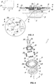
FIG. 1 is a perspective view of the multifunctional rotary tool of the invention during processing of a block of pages to be bound; -
FIG. 2 is a top view of the tool ofFig. 1 during processing of the block; -
FIG. 3 is a lateral broken-away view of the tool ofFig. 1 during processing of the block with a respective magnification; -
FIG. 4 is an exploded perspective view of the tool ofFig. 1 ; -
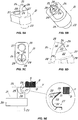
FIGS. 5A to 5E are perspective, top, enlarged perspective and lateral views respectively, with respective magnifications, of the tool ofFig. 1 . - Particularly referring to the figures, there is shown a multifunction rotary tool, generally designated by numeral 1, which is designed to be installed on a bookbinding machine to perform milling and roughening operations on the back D of blocks B of pages S to be bound.
- Such operations have the purpose to increase the surface of the back D of the blocks B that is available for further application of a coat of glue, allowing a flexible cover to be attached to the back D.
- The bookbinding machine, not shown, comprises a advancement plane P for feeding the blocks B in a substantially horizontal direction L and a motorized
spindle 2 with a multifunction tool 1 mounted thereon. - Conveniently, the block B may be fed by means of a motorized clamp, not shown, whose plates are adapted to retain the block B at its side walls.
- In the embodiment of the figures, the multifunction tool 1 comprises a
cylindrical base 3 defining a substantially vertical axis of rotation V, and adapted to be coupled to the motorizedspindle 2 of the machine. - The
cylindrical base 3 may comprise acentral hole 4 for receiving thespindle 2 and will be adapted to be coupled thereto by means of a key, as best shown inFIG. 4 or a tongue, a shrink disk, a square shaft, a spline shaft or other similar coupling types. - Furthermore, the
cylindrical base 3 has atop surface 5 with first 6 and second 7 sets of radially and angularly offset holes. - The tool 1 further comprises a first
annular member 9 that can be coaxially secured to thecylindrical base 3 and has a substantially circular outerperipheral edge 10. - As best shown in
FIGS. 1 to 4 , the firstannular member 9 comprises a crown of milling blades 11 formed at its outerperipheral edge 10 and defining a cutting plane π substantially perpendicular to the vertical axis of rotation V. - Each of the blades 11 comprises a
front cutting portion 12 and anupper cutting portion 13 which are adapted to remove the material from the back D of the block B as the latter is fed on the surface P of the machine and thecylindrical base 3 is rotated. - The first
annular member 9 may comprise a plurality of throughholes 14 that are angularly arranged and can be aligned with the threadedholes 8 of thefirst set 6, formed on the base to receivescrews 15 for removably securing the firstannular member 9 to thebase 3. - Conveniently, a second
annular member 16 may be provided, whose diameter is smaller than that of the first and can be removably secured to thecylindrical base 3. - As shown in
FIGS. 1 to 4 , the secondannular member 16 may comprise, on itstop surface 17, a plurality ofbrushes 18 that project upwards from the cutting plane π and are adapted to remove any processing residues from the back D of the blocks B. - Furthermore, a pair of third central
annular members 19, 19' may be provided, for maintaining theannular members base 3, by means of appropriate connectingscrews 20. - The multifunctional tool 1 also comprises a plurality of roughening
inserts 21, as best shown inFIGS. 5A to 5E , which are adapted to be removably secured to thecylindrical base 3 along acircular area 22 that is radially inwardly offset relative to the crown of milling blades 11. - The
roughening inserts 21 partially project relative to the cutting plane π of the milling blades 11, as best shown inFIG. 3 , to cut the back D of the block that is being fed on the surface P of the machine as thebase 3 is rotated, and may be arranged along circumferences C1, C2 that are substantially concentric with respect to the axis of rotation V. - Thus, the block B that is being fed along the surface P of the bookbinding machine will first interact with the milling blades 11 and then with the
roughening inserts 21. - Of course, the
roughening inserts 21 may be arranged along further circumferences without departure from the scope of the present invention. - According to a peculiar aspect of the invention, each
roughening insert 21 comprises acylindrical body 23 with a substantially hook-shaped end portion 24 defined by a substantially straightupper edge 25, as best shown inFIGS. 5A to 5E . - The
upper edge 25 has asharp tip 26, as best shown inFIGS. 5D and 5R, which is adapted to penetrate the back D of the block B and cut it in a direction Y substantially perpendicular thereto. - Furthermore, the
end portion 24 of eachroughening insert 21 comprises an at least partially curvedrecessed surface 27, as best shown inFIG. 5D , which is adapted to tear and push downwards the cut material without removing it. - Therefore, the multifunctional rotary tool 1 of the invention is able to mill and rough the back D of the blocks B of pages S to be bound while considerably increasing the surface thereof that is available for application and distribution of the glue, without removing any material therefrom, and without damaging the parts of the block B contiguous to the back D, that require no processing.
- Preferably, the
end portion 24 of eachinsert 21 may comprise a pair of substantially flat side surfaces 28 which converge toward theupper edge 25 and side edges 29 defined by the intersection of the side surfaces 28 with the recessedsurface 27. - Furthermore, the
upper edge 25 is chamfered and has afirst section 30 inclined with respect to the cutting plane π and asecond section 31 substantially parallel to the cutting plane π and defining thesharp tip 26. - Particularly, as best shown in the enlargement of
FIG. 3 , thesharp tip 26 and part of the firstinclined section 30 of theupper edge 25 will project relative to the cutting plane π of the blades 11 to interact with the back D of the block B in the direction Y perpendicular thereto. - The inclination of the
inclined section 30 is selected in such a manner that, as the tool 1 rotates, eachinsert 21 will only interact with the back D of the block B at thesharp tip 26, thereby preventing shocks and damages to the parts of the block that are not designed to be processed. - The recessed
surface 27 comprises a substantially cylindricallower portion 32 and a substantially flat and straightupper portion 33, as best shown inFIGS. 5D and 5E . - Advantageously, the side edges 29 are curved at the
lower portion 32 and planar and inclined at theupper portion 33. - The
bevels 34 formed at theupper edge 25 and the side edges 29 of theend portion 24 of eachinsert 21 eliminate the sharp edges that might cause material removal during roughening of the back D. - Conversely, the roughening inserts 21 as used in the present invention carry out notching of the back D of blocks B by tearing the material fibers and pushing the material downwards.
- Conveniently, each
insert 21 comprises asupport 35 having a generally prismatic shape, possibly with rounded corners, in which thecylindrical body 23 is accommodated and housed in a corresponding throughcavity 36 having a mating shape, formed in the firstannular member 9. - Of course, the shape of the
support 35 and thecavities 36 may also be other than a prismatic shape, without departure from the scope of the present claims. - The first
annular member 35 may comprise a plurality of throughholes 37 that are angularly arranged and can be aligned with the threadedholes 8 of the first set 7, formed on the base to receivescrews 38 for removably securing theinsert member 21 to thebase 3. - This feature greatly simplifies maintenance of the tool 1, as it allows replacement of damaged or worn roughening inserts 21 only, without requiring replacement of a whole crown of inserts, unlike prior art tools.
- The first
annular member 9 may comprise at least twoseries cavities 36 that are angularly offset and radially arranged in respective circular paths concentric with the axis of rotation, radially offset and corresponding to the circumferences C1, C2. - In the embodiment of the figures, the tool 1 has an
outer series 39 having eight throughcavities 36 and aninner series 40 having four throughcavities 36, and each of thecavities 36 is adapted to accommodate arespective insert 21 with its correspondingsupport 35. - In an alternative embodiment of the invention, not shown, the roughening inserts 21 may be fitted in some of the through
cavities 36, according to particular types of notching to be carried out on the back D of blocks B. - In a further aspect, the invention relates to a bookbinding machine, not shown, for binding blocks B of packed pages S, which comprises a advancement plane P for feeding the blocks B in a substantially horizontal direction L and a load unit for loading the blocks B with the back lying on the advancement plane P.
- The machine comprises a
motorized spindle 2 with a substantially vertical axis of rotation V having the above described multifunctional rotary tool 1 mounted thereto. - The tool 1 installed in the bookbinding machine allows the back D of the blocks to be milled using the crown of milling blades 11 and roughed using the plurality of roughening inserts 21 which are adapted to cut the material of the blocks B without removing it.
- The tool and the machine of the invention are susceptible to a number of changes or variants, within the inventive concept disclosed in the appended claims. All the details thereof may be replaced by other technically equivalent parts, and the materials may vary depending on different needs, without departure from the scope of the invention, as defined in the appended claims.
- While the tool and the machine have been described with particular reference to the accompanying figures, the numerals referred to in the disclosure and claims are only used for the sake of a better intelligibility of the invention and shall not be intended to limit the claimed scope in any manner.
- The present invention may find application in industry, because it can be produced on an industrial scale in the publishing and bookbinding industries.
Claims (11)
- A multifunction rotary tool (1) for bookbinding machines, particularly for milling and roughening the back (D) of blocks (B) of pages (S) to be bound, wherein the bookbinding machine comprises a substantially horizontal advancement plane (P) for feeding the blocks (B) and a motorized spindle (2), which tool (1) comprises:- a cylindrical base (3) defining an axis of rotation (V) and adapted to be coupled to a motorized spindle (2) of the bookbinding machine;- a first annular member (9) designed to be coaxially secured to said cylindrical base (3) and having a substantially circular outer peripheral edge (10);- a crown of milling blades (11) formed in said first annular member (9) proximate to its outer peripheral edge (10) and defining a cutting plane (π) substantially perpendicular to said axis of rotation (V);- a plurality of roughening inserts (21), which are adapted to be removably secured to said cylindrical base (3) along a circular area (22) that is radially inwardly offset relative to said crown of milling blades (11);characterized in that each roughening insert (21) comprises a cylindrical body (23) with an end portion (24) having a substantially hook-like shape defined by an upper edge (25) with a sharp tip (26) which is designed to penetrate the back (D) of the block (B) and cut it along a direction (Y) substantially perpendicular thereto, and an at least partially curved recessed surface (27), which is adapted to tear apart and push downwards the cut material without removing it.
- A tool as claimed in claim 1, characterized in that said end portion (24) comprises a pair of substantially planar side surfaces (28) which converge toward said upper edge (25) and side edges (29) defined by the intersection of said side surfaces (28) with said recessed surface (27).
- A tool as claimed in claim 1, characterized in that said upper edge (25) is chamfered and has a first section (30) inclined with respect to said cutting plane (π) and a second section (31) substantially parallel to said cutting plane (π) and defining said sharp tip (26).
- A tool as claimed in claim 2, characterized in that said recessed surface (27) comprises a substantially cylindrical lower portion (32), which is joined to a substantially planar and inclined upper portion (33).
- A tool as claimed in claim 4, characterized in that said side edges (29) are curved at said lower portion (32) and straight and chamfered at said upper portion (33).
- A tool as claimed in claim 1, characterized in that said roughening inserts (21) are arranged along circumferences (C1, C2) substantially concentric with said axis of rotation (V).
- A tool as claimed in claim 6, characterized in that each insert (21) comprises a substantially prismatic support (35) with said cylindrical body (23) inserted therein, which is shaped to be housed in a corresponding through cavity (36) formed in said first annular member (9) said support (35) having through holes (37) for respective anchor screws (38).
- A tool as claimed in claim 7, characterized in that it comprises at least two series (39, 40) of through cavities (36) that are angularly offset in respective circular paths concentric with said axis of rotation (V), radially offset and corresponding to said circumferences (C1, C2).
- A tool as claimed in claim 7, characterized in that said base (3) comprises a first set (6) of threaded holes (8) for anchor screws (15) for securing said first annular member (9) to said base (3) and a second set (7) of threaded holes (8) aligned with said through cavities (36) for securing said inserts (21) to said base (3).
- A tool as claimed in claim 1, characterized in that it comprises a second annular member (16) whose diameter is smaller than that of said first annular member (9) and configured to be removably secured to said cylindrical base (3), said second annular member (16) having a plurality of brushes (18) projecting upwards from said cutting plane (π).
- A bookbinding machine for binding blocks (B) of packed pages (P), comprising an advancement plane (P), for feeding the blocks in a substantially horizontal direction (L), a load unit for loading the blocks (B) with the back (D) lying on advancement plane (P), a motorized spindle (2) with a substantially vertical axis of rotation (V), a tool (1) mounted to said spindle (2) and guide means for guiding the blocks (B) being processed by intersecting said axis of rotation (V), characterized in that said tool (1) is a multifunction tool (1) as claimed in one or more of claims 1 to 10, for milling the back (D) of the blocks (B) using the crown of peripheral blades (11) and roughening the back (D) of the blocks (B) using said plurality of roughening inserts (21) to cut the material of the blocks (B) without removing it.
Applications Claiming Priority (2)
| Application Number | Priority Date | Filing Date | Title |
|---|---|---|---|
| ITUA2016A001988A ITUA20161988A1 (en) | 2016-03-24 | 2016-03-24 | MULTIFUNCTIONAL ROTARY TOOL FOR BROSSURATRIC MACHINES |
| PCT/IB2017/051677 WO2017163206A1 (en) | 2016-03-24 | 2017-03-23 | A multifunctional rotary tool for bookbinding machines and a bookbinding machine |
Publications (2)
| Publication Number | Publication Date |
|---|---|
| EP3433106A1 EP3433106A1 (en) | 2019-01-30 |
| EP3433106B1 true EP3433106B1 (en) | 2020-02-12 |
Family
ID=56235883
Family Applications (1)
| Application Number | Title | Priority Date | Filing Date |
|---|---|---|---|
| EP17724278.1A Active EP3433106B1 (en) | 2016-03-24 | 2017-03-23 | A multifunctional rotary tool for bookbinding machines and a bookbinding machine |
Country Status (4)
| Country | Link |
|---|---|
| US (1) | US10744809B2 (en) |
| EP (1) | EP3433106B1 (en) |
| IT (1) | ITUA20161988A1 (en) |
| WO (1) | WO2017163206A1 (en) |
Family Cites Families (10)
| Publication number | Priority date | Publication date | Assignee | Title |
|---|---|---|---|---|
| CH303678A (en) * | 1952-07-30 | 1954-12-15 | Mueller Hans | Method and device for threadless binding of books. |
| DE2719402A1 (en) * | 1977-04-30 | 1978-11-02 | Rahdener Maschf August | METHOD FOR BINDING BOOKS OR THE LIKE AFTER THE ADHESIVE BINDING TECHNOLOGY AND DEVICE FOR CARRYING OUT THE METHOD |
| DE19650851A1 (en) * | 1996-11-27 | 1998-05-28 | B P S Buessenschuett Projekte | Device for treating spines of stacked sheets to be bound into books, periodicals, etc. |
| DE10022836B4 (en) * | 2000-05-10 | 2008-07-10 | Kolbus Gmbh & Co. Kg | Device for the back processing of book blocks |
| DE10230054A1 (en) * | 2002-07-04 | 2004-01-22 | Heidelberger Druckmaschinen Ag | Device for processing side edges of sheet-shaped substrates |
| US7736099B2 (en) * | 2005-12-16 | 2010-06-15 | Cole Carbide Industries, Inc. | Gear milling tool with replaceable cutting inserts |
| JP4326543B2 (en) * | 2006-04-27 | 2009-09-09 | ホリゾン・インターナショナル株式会社 | Wireless binding processing apparatus |
| IL185047A (en) * | 2007-08-05 | 2011-09-27 | Iscar Ltd | Cutting tool |
| DE102011105033A1 (en) * | 2011-06-20 | 2012-12-20 | Heidelberger Druckmaschinen Ag | Device for the back processing of book blocks |
| US20130294854A1 (en) * | 2012-05-02 | 2013-11-07 | Taegutec, Ltd. | Cutting tool assembly |
-
2016
- 2016-03-24 IT ITUA2016A001988A patent/ITUA20161988A1/en unknown
-
2017
- 2017-03-23 US US16/085,764 patent/US10744809B2/en active Active
- 2017-03-23 EP EP17724278.1A patent/EP3433106B1/en active Active
- 2017-03-23 WO PCT/IB2017/051677 patent/WO2017163206A1/en active Application Filing
Non-Patent Citations (1)
| Title |
|---|
| None * |
Also Published As
| Publication number | Publication date |
|---|---|
| US20190092072A1 (en) | 2019-03-28 |
| US10744809B2 (en) | 2020-08-18 |
| WO2017163206A1 (en) | 2017-09-28 |
| ITUA20161988A1 (en) | 2017-09-24 |
| EP3433106A1 (en) | 2019-01-30 |
Similar Documents
| Publication | Publication Date | Title |
|---|---|---|
| EP2623240B1 (en) | Blade edge exchangeable cutting tool | |
| US8573903B2 (en) | Round cutting insert with anti-rotation feature | |
| EP2440351B1 (en) | Cutting tool and cutting insert for the same | |
| KR101677917B1 (en) | end milling cutter for processing of fiber reinforced materials such as carbon fiber reinforced plastics | |
| US20120189393A1 (en) | Modular drill with diamond cutting edges | |
| CN102056694A (en) | Cutting insert | |
| JPH0698523B2 (en) | Cutting insert | |
| JP6006829B2 (en) | Chamfering blade and chamfering cutter | |
| US20210154877A1 (en) | Accessory for Oscillating Power Tool | |
| US20140294524A1 (en) | Pentagon-shaped cutting insert and slotting cutter therefor | |
| EP0321391A2 (en) | Planing tool for a woodworking machine | |
| JP3777043B2 (en) | Cutting tool using round piece type throwaway insert | |
| EP3052326B1 (en) | Supporting plate for self-centring chucks | |
| EP3433106B1 (en) | A multifunctional rotary tool for bookbinding machines and a bookbinding machine | |
| KR101419493B1 (en) | Rotary tissue cutting device | |
| US3300834A (en) | Milling cutter tool | |
| EP1237671B1 (en) | Slotting cutter | |
| CN102528145B (en) | Lathe | |
| GB2079656A (en) | Rotary cutting tools with plural cutting blades | |
| US10744577B2 (en) | Cutting insert positioning cartridge and system for a machining tool and a machining tool comprising such a positioning system | |
| EP2131984B1 (en) | Indexable cutting insert and method of machining | |
| JP2016032860A (en) | Cutting insert and tooth point replaceable cutting tool | |
| CN212288929U (en) | Cutter and cutter assembly | |
| KR0143621B1 (en) | Cutting machine of a sand paper | |
| JP4353068B2 (en) | Cutting head replaceable cutting tool |
Legal Events
| Date | Code | Title | Description |
|---|---|---|---|
| STAA | Information on the status of an ep patent application or granted ep patent |
Free format text: STATUS: UNKNOWN |
|
| STAA | Information on the status of an ep patent application or granted ep patent |
Free format text: STATUS: THE INTERNATIONAL PUBLICATION HAS BEEN MADE |
|
| PUAI | Public reference made under article 153(3) epc to a published international application that has entered the european phase |
Free format text: ORIGINAL CODE: 0009012 |
|
| STAA | Information on the status of an ep patent application or granted ep patent |
Free format text: STATUS: REQUEST FOR EXAMINATION WAS MADE |
|
| 17P | Request for examination filed |
Effective date: 20181008 |
|
| AK | Designated contracting states |
Kind code of ref document: A1 Designated state(s): AL AT BE BG CH CY CZ DE DK EE ES FI FR GB GR HR HU IE IS IT LI LT LU LV MC MK MT NL NO PL PT RO RS SE SI SK SM TR |
|
| AX | Request for extension of the european patent |
Extension state: BA ME |
|
| GRAP | Despatch of communication of intention to grant a patent |
Free format text: ORIGINAL CODE: EPIDOSNIGR1 |
|
| STAA | Information on the status of an ep patent application or granted ep patent |
Free format text: STATUS: GRANT OF PATENT IS INTENDED |
|
| DAV | Request for validation of the european patent (deleted) | ||
| DAX | Request for extension of the european patent (deleted) | ||
| INTG | Intention to grant announced |
Effective date: 20190415 |
|
| INTC | Intention to grant announced (deleted) | ||
| GRAP | Despatch of communication of intention to grant a patent |
Free format text: ORIGINAL CODE: EPIDOSNIGR1 |
|
| INTG | Intention to grant announced |
Effective date: 20190729 |
|
| GRAS | Grant fee paid |
Free format text: ORIGINAL CODE: EPIDOSNIGR3 |
|
| GRAA | (expected) grant |
Free format text: ORIGINAL CODE: 0009210 |
|
| STAA | Information on the status of an ep patent application or granted ep patent |
Free format text: STATUS: THE PATENT HAS BEEN GRANTED |
|
| AK | Designated contracting states |
Kind code of ref document: B1 Designated state(s): AL AT BE BG CH CY CZ DE DK EE ES FI FR GB GR HR HU IE IS IT LI LT LU LV MC MK MT NL NO PL PT RO RS SE SI SK SM TR |
|
| REG | Reference to a national code |
Ref country code: GB Ref legal event code: FG4D |
|
| REG | Reference to a national code |
Ref country code: CH Ref legal event code: EP |
|
| REG | Reference to a national code |
Ref country code: AT Ref legal event code: REF Ref document number: 1231594 Country of ref document: AT Kind code of ref document: T Effective date: 20200215 |
|
| REG | Reference to a national code |
Ref country code: DE Ref legal event code: R096 Ref document number: 602017011692 Country of ref document: DE |
|
| REG | Reference to a national code |
Ref country code: IE Ref legal event code: FG4D |
|
| REG | Reference to a national code |
Ref country code: SE Ref legal event code: TRGR |
|
| PG25 | Lapsed in a contracting state [announced via postgrant information from national office to epo] |
Ref country code: FI Free format text: LAPSE BECAUSE OF FAILURE TO SUBMIT A TRANSLATION OF THE DESCRIPTION OR TO PAY THE FEE WITHIN THE PRESCRIBED TIME-LIMIT Effective date: 20200212 Ref country code: RS Free format text: LAPSE BECAUSE OF FAILURE TO SUBMIT A TRANSLATION OF THE DESCRIPTION OR TO PAY THE FEE WITHIN THE PRESCRIBED TIME-LIMIT Effective date: 20200212 Ref country code: NO Free format text: LAPSE BECAUSE OF FAILURE TO SUBMIT A TRANSLATION OF THE DESCRIPTION OR TO PAY THE FEE WITHIN THE PRESCRIBED TIME-LIMIT Effective date: 20200512 |
|
| REG | Reference to a national code |
Ref country code: LT Ref legal event code: MG4D |
|
| REG | Reference to a national code |
Ref country code: NL Ref legal event code: MP Effective date: 20200212 |
|
| PG25 | Lapsed in a contracting state [announced via postgrant information from national office to epo] |
Ref country code: BG Free format text: LAPSE BECAUSE OF FAILURE TO SUBMIT A TRANSLATION OF THE DESCRIPTION OR TO PAY THE FEE WITHIN THE PRESCRIBED TIME-LIMIT Effective date: 20200512 Ref country code: IS Free format text: LAPSE BECAUSE OF FAILURE TO SUBMIT A TRANSLATION OF THE DESCRIPTION OR TO PAY THE FEE WITHIN THE PRESCRIBED TIME-LIMIT Effective date: 20200612 Ref country code: LV Free format text: LAPSE BECAUSE OF FAILURE TO SUBMIT A TRANSLATION OF THE DESCRIPTION OR TO PAY THE FEE WITHIN THE PRESCRIBED TIME-LIMIT Effective date: 20200212 Ref country code: GR Free format text: LAPSE BECAUSE OF FAILURE TO SUBMIT A TRANSLATION OF THE DESCRIPTION OR TO PAY THE FEE WITHIN THE PRESCRIBED TIME-LIMIT Effective date: 20200513 Ref country code: HR Free format text: LAPSE BECAUSE OF FAILURE TO SUBMIT A TRANSLATION OF THE DESCRIPTION OR TO PAY THE FEE WITHIN THE PRESCRIBED TIME-LIMIT Effective date: 20200212 |
|
| PG25 | Lapsed in a contracting state [announced via postgrant information from national office to epo] |
Ref country code: NL Free format text: LAPSE BECAUSE OF FAILURE TO SUBMIT A TRANSLATION OF THE DESCRIPTION OR TO PAY THE FEE WITHIN THE PRESCRIBED TIME-LIMIT Effective date: 20200212 |
|
| PG25 | Lapsed in a contracting state [announced via postgrant information from national office to epo] |
Ref country code: ES Free format text: LAPSE BECAUSE OF FAILURE TO SUBMIT A TRANSLATION OF THE DESCRIPTION OR TO PAY THE FEE WITHIN THE PRESCRIBED TIME-LIMIT Effective date: 20200212 Ref country code: DK Free format text: LAPSE BECAUSE OF FAILURE TO SUBMIT A TRANSLATION OF THE DESCRIPTION OR TO PAY THE FEE WITHIN THE PRESCRIBED TIME-LIMIT Effective date: 20200212 Ref country code: SK Free format text: LAPSE BECAUSE OF FAILURE TO SUBMIT A TRANSLATION OF THE DESCRIPTION OR TO PAY THE FEE WITHIN THE PRESCRIBED TIME-LIMIT Effective date: 20200212 Ref country code: SM Free format text: LAPSE BECAUSE OF FAILURE TO SUBMIT A TRANSLATION OF THE DESCRIPTION OR TO PAY THE FEE WITHIN THE PRESCRIBED TIME-LIMIT Effective date: 20200212 Ref country code: EE Free format text: LAPSE BECAUSE OF FAILURE TO SUBMIT A TRANSLATION OF THE DESCRIPTION OR TO PAY THE FEE WITHIN THE PRESCRIBED TIME-LIMIT Effective date: 20200212 Ref country code: CZ Free format text: LAPSE BECAUSE OF FAILURE TO SUBMIT A TRANSLATION OF THE DESCRIPTION OR TO PAY THE FEE WITHIN THE PRESCRIBED TIME-LIMIT Effective date: 20200212 Ref country code: PT Free format text: LAPSE BECAUSE OF FAILURE TO SUBMIT A TRANSLATION OF THE DESCRIPTION OR TO PAY THE FEE WITHIN THE PRESCRIBED TIME-LIMIT Effective date: 20200705 Ref country code: RO Free format text: LAPSE BECAUSE OF FAILURE TO SUBMIT A TRANSLATION OF THE DESCRIPTION OR TO PAY THE FEE WITHIN THE PRESCRIBED TIME-LIMIT Effective date: 20200212 Ref country code: LT Free format text: LAPSE BECAUSE OF FAILURE TO SUBMIT A TRANSLATION OF THE DESCRIPTION OR TO PAY THE FEE WITHIN THE PRESCRIBED TIME-LIMIT Effective date: 20200212 |
|
| REG | Reference to a national code |
Ref country code: DE Ref legal event code: R097 Ref document number: 602017011692 Country of ref document: DE |
|
| REG | Reference to a national code |
Ref country code: AT Ref legal event code: MK05 Ref document number: 1231594 Country of ref document: AT Kind code of ref document: T Effective date: 20200212 |
|
| PG25 | Lapsed in a contracting state [announced via postgrant information from national office to epo] |
Ref country code: MC Free format text: LAPSE BECAUSE OF FAILURE TO SUBMIT A TRANSLATION OF THE DESCRIPTION OR TO PAY THE FEE WITHIN THE PRESCRIBED TIME-LIMIT Effective date: 20200212 |
|
| PLBE | No opposition filed within time limit |
Free format text: ORIGINAL CODE: 0009261 |
|
| STAA | Information on the status of an ep patent application or granted ep patent |
Free format text: STATUS: NO OPPOSITION FILED WITHIN TIME LIMIT |
|
| REG | Reference to a national code |
Ref country code: BE Ref legal event code: MM Effective date: 20200331 |
|
| PG25 | Lapsed in a contracting state [announced via postgrant information from national office to epo] |
Ref country code: LU Free format text: LAPSE BECAUSE OF NON-PAYMENT OF DUE FEES Effective date: 20200323 |
|
| 26N | No opposition filed |
Effective date: 20201113 |
|
| PG25 | Lapsed in a contracting state [announced via postgrant information from national office to epo] |
Ref country code: AT Free format text: LAPSE BECAUSE OF FAILURE TO SUBMIT A TRANSLATION OF THE DESCRIPTION OR TO PAY THE FEE WITHIN THE PRESCRIBED TIME-LIMIT Effective date: 20200212 |
|
| PG25 | Lapsed in a contracting state [announced via postgrant information from national office to epo] |
Ref country code: BE Free format text: LAPSE BECAUSE OF NON-PAYMENT OF DUE FEES Effective date: 20200331 Ref country code: SI Free format text: LAPSE BECAUSE OF FAILURE TO SUBMIT A TRANSLATION OF THE DESCRIPTION OR TO PAY THE FEE WITHIN THE PRESCRIBED TIME-LIMIT Effective date: 20200212 Ref country code: PL Free format text: LAPSE BECAUSE OF FAILURE TO SUBMIT A TRANSLATION OF THE DESCRIPTION OR TO PAY THE FEE WITHIN THE PRESCRIBED TIME-LIMIT Effective date: 20200212 |
|
| PGFP | Annual fee paid to national office [announced via postgrant information from national office to epo] |
Ref country code: IE Payment date: 20220321 Year of fee payment: 6 Ref country code: CH Payment date: 20220324 Year of fee payment: 6 |
|
| PG25 | Lapsed in a contracting state [announced via postgrant information from national office to epo] |
Ref country code: TR Free format text: LAPSE BECAUSE OF FAILURE TO SUBMIT A TRANSLATION OF THE DESCRIPTION OR TO PAY THE FEE WITHIN THE PRESCRIBED TIME-LIMIT Effective date: 20200212 Ref country code: MT Free format text: LAPSE BECAUSE OF FAILURE TO SUBMIT A TRANSLATION OF THE DESCRIPTION OR TO PAY THE FEE WITHIN THE PRESCRIBED TIME-LIMIT Effective date: 20200212 Ref country code: CY Free format text: LAPSE BECAUSE OF FAILURE TO SUBMIT A TRANSLATION OF THE DESCRIPTION OR TO PAY THE FEE WITHIN THE PRESCRIBED TIME-LIMIT Effective date: 20200212 |
|
| PGFP | Annual fee paid to national office [announced via postgrant information from national office to epo] |
Ref country code: SE Payment date: 20220324 Year of fee payment: 6 |
|
| PG25 | Lapsed in a contracting state [announced via postgrant information from national office to epo] |
Ref country code: MK Free format text: LAPSE BECAUSE OF FAILURE TO SUBMIT A TRANSLATION OF THE DESCRIPTION OR TO PAY THE FEE WITHIN THE PRESCRIBED TIME-LIMIT Effective date: 20200212 Ref country code: AL Free format text: LAPSE BECAUSE OF FAILURE TO SUBMIT A TRANSLATION OF THE DESCRIPTION OR TO PAY THE FEE WITHIN THE PRESCRIBED TIME-LIMIT Effective date: 20200212 |
|
| PGFP | Annual fee paid to national office [announced via postgrant information from national office to epo] |
Ref country code: FR Payment date: 20230323 Year of fee payment: 7 |
|
| PGFP | Annual fee paid to national office [announced via postgrant information from national office to epo] |
Ref country code: IT Payment date: 20230321 Year of fee payment: 7 Ref country code: GB Payment date: 20230321 Year of fee payment: 7 Ref country code: DE Payment date: 20230328 Year of fee payment: 7 |
|
| P01 | Opt-out of the competence of the unified patent court (upc) registered |
Effective date: 20230606 |
|
| REG | Reference to a national code |
Ref country code: CH Ref legal event code: PL Ref country code: SE Ref legal event code: EUG |
|
| REG | Reference to a national code |
Ref country code: IE Ref legal event code: MM4A |
|
| PG25 | Lapsed in a contracting state [announced via postgrant information from national office to epo] |
Ref country code: SE Free format text: LAPSE BECAUSE OF NON-PAYMENT OF DUE FEES Effective date: 20230324 Ref country code: LI Free format text: LAPSE BECAUSE OF NON-PAYMENT OF DUE FEES Effective date: 20230331 Ref country code: IE Free format text: LAPSE BECAUSE OF NON-PAYMENT OF DUE FEES Effective date: 20230323 Ref country code: CH Free format text: LAPSE BECAUSE OF NON-PAYMENT OF DUE FEES Effective date: 20230331 |