EP3433018B1 - Roller mill system with rejects removal system - Google Patents
Roller mill system with rejects removal system Download PDFInfo
- Publication number
- EP3433018B1 EP3433018B1 EP17715344.2A EP17715344A EP3433018B1 EP 3433018 B1 EP3433018 B1 EP 3433018B1 EP 17715344 A EP17715344 A EP 17715344A EP 3433018 B1 EP3433018 B1 EP 3433018B1
- Authority
- EP
- European Patent Office
- Prior art keywords
- classifier
- rejects
- roller mill
- zone
- grinding
- Prior art date
- Legal status (The legal status is an assumption and is not a legal conclusion. Google has not performed a legal analysis and makes no representation as to the accuracy of the status listed.)
- Revoked
Links
Images


Classifications
-
- B—PERFORMING OPERATIONS; TRANSPORTING
- B02—CRUSHING, PULVERISING, OR DISINTEGRATING; PREPARATORY TREATMENT OF GRAIN FOR MILLING
- B02C—CRUSHING, PULVERISING, OR DISINTEGRATING IN GENERAL; MILLING GRAIN
- B02C23/00—Auxiliary methods or auxiliary devices or accessories specially adapted for crushing or disintegrating not provided for in preceding groups or not specially adapted to apparatus covered by a single preceding group
- B02C23/18—Adding fluid, other than for crushing or disintegrating by fluid energy
- B02C23/24—Passing gas through crushing or disintegrating zone
- B02C23/30—Passing gas through crushing or disintegrating zone the applied gas acting to effect material separation
-
- B—PERFORMING OPERATIONS; TRANSPORTING
- B02—CRUSHING, PULVERISING, OR DISINTEGRATING; PREPARATORY TREATMENT OF GRAIN FOR MILLING
- B02C—CRUSHING, PULVERISING, OR DISINTEGRATING IN GENERAL; MILLING GRAIN
- B02C15/00—Disintegrating by milling members in the form of rollers or balls co-operating with rings or discs
- B02C15/02—Centrifugal pendulum-type mills
-
- B—PERFORMING OPERATIONS; TRANSPORTING
- B02—CRUSHING, PULVERISING, OR DISINTEGRATING; PREPARATORY TREATMENT OF GRAIN FOR MILLING
- B02C—CRUSHING, PULVERISING, OR DISINTEGRATING IN GENERAL; MILLING GRAIN
- B02C15/00—Disintegrating by milling members in the form of rollers or balls co-operating with rings or discs
- B02C15/04—Mills with pressed pendularly-mounted rollers, e.g. spring pressed
- B02C15/045—Mills with pressed pendularly-mounted rollers, e.g. spring pressed pressed against the interior of a ring rotating in a vertical plane
-
- B—PERFORMING OPERATIONS; TRANSPORTING
- B02—CRUSHING, PULVERISING, OR DISINTEGRATING; PREPARATORY TREATMENT OF GRAIN FOR MILLING
- B02C—CRUSHING, PULVERISING, OR DISINTEGRATING IN GENERAL; MILLING GRAIN
- B02C15/00—Disintegrating by milling members in the form of rollers or balls co-operating with rings or discs
- B02C15/001—Air flow directing means positioned on the periphery of the horizontally rotating milling surface
-
- B—PERFORMING OPERATIONS; TRANSPORTING
- B02—CRUSHING, PULVERISING, OR DISINTEGRATING; PREPARATORY TREATMENT OF GRAIN FOR MILLING
- B02C—CRUSHING, PULVERISING, OR DISINTEGRATING IN GENERAL; MILLING GRAIN
- B02C15/00—Disintegrating by milling members in the form of rollers or balls co-operating with rings or discs
- B02C2015/002—Disintegrating by milling members in the form of rollers or balls co-operating with rings or discs combined with a classifier
Definitions
- the present invention is directed to a roller mill system for producing fine ground particles, and more specifically to such a roller mill system having a bottom discharge port and/or a turbine classifier with a side discharge port for removal of rejects, such as grit, from a stream of particles being processed in the mill.
- grinding mills are typically employed to grind solid materials such as minerals, clay, limestone, gypsum, phosphate rock, salt, coke, biomass and coal into small particles for use in a wide range of processes such as for combustion in furnaces and for chemical reactions in reactor systems.
- the ball mills typically include a horizontal rotating cylinder containing a charge of tumbling or cascading balls.
- roller mill is a pendulum mill which includes a support shaft rotationally supported by a bearing housing. One end of the shaft is coupled to a drive unit for rotating the shaft. An opposing end of the shaft has a hub mounted thereto.
- a plurality of arms extend from the hub.
- Each of the arms pivotally supports a roller journal which has a roller rotatingly coupled to an end thereof.
- the rollers rollingly engage the grinding ring.
- centrifugal forces drive the crushing members against the grinding ring.
- the crushing members pulverize the solid material against the grinding ring as a result of contact with the grinding ring.
- a roller mill 100 includes, for example, a vessel 110 in which a bowl assembly 112 is mounted.
- the exemplary roller mill 100 include grinding rollers 118 each mounted on a suitably supported journal 120.
- the journals 120 are connected for rotation to a drive shaft 122 via support arms 121.
- the grinding rollers 118 interact with a grinding surface of the bowl assembly 112 to effect the grinding of material interposed therebetween.
- the particles of material After being pulverized, the particles of material are thrown outwardly by centrifugal force whereby the particles of material are fed into a stream of air that is entering the mill 100 via an annular manifold 117.
- the flow of air is through the mill 100 is caused by a fan 119 that is in communication with a discharge duct 123 of the mill 100.
- the fan 119 circulates air and pulverized fine particles entrained in the air into a separator 125 (e.g., a cyclone separator or bag house) that separates the fine particles and discharges them via an outlet 125D.
- Circulating air that has most of the fine particles removed therefrom is discharged from the separator 125 via the clean air port 125A and circulated back to the annular manifold 117.
- Prior art mills 100 typically employed a classifier 130 in a classifier section of the mill 100 located downstream of the grinding rollers 118 and upstream of the fan 119 proximate the discharge duct 123 of the mill 100.
- the stream of air with the particles of material entrained therein flows into a classifier 130 in which coarse particles of material are intended to be rejected from the air stream. These coarse material particles are then supposed to be returned to the grinding area for further pulverization, while the fine particles of material are supposed to be carried through the mill 100 in the air stream, and exit along with the air.
- one prior art classifier 130 is known as a "whizzer separator" as disclosed in U.S. Patent No. 2,108,609 .
- One of the prior art classifiers 130 may be employed for the classification of the coarse particles or two or more of the prior art classifiers 130 may be employed in a series configuration.
- the prior art classifier 130 includes a closed central disc 138 that is secured to a rotatable shaft 130S.
- a plurality of blades 139 extend radially outward from the disc 138.
- the blades 139 are beveled inwardly and upwardly thereby defining an inclined edge 140.
- a conical deflector 141 is secured to a wall 130W of the classifier section of the mill 100.
- the conical deflector 141 defines a outwardly and downwardly sloped surface 141C.
- the inclined edge 140 of the blades 139 rotate in close proximity to the sloped surface 141C. There is a gap G between the sloped surface 141C and the inclined edge 140.
- the applicant has conducted computational fluid dynamics (CFD) analysis on the prior art classifiers 130 to determine particle velocity distributions upstream and downstream of the classifier and to determine particle size distribution.
- CFD computational fluid dynamics
- the CFD analysis demonstrated that the velocity profile of the particles upstream of the prior art classifier 130 were substantially straight and vertical with essentially no tangential velocity component or swirl.
- Such a velocity profile allow all sized particles, larger or small, to approach and enter the prior art classifier 130, without rejecting any of the larger particles.
- the separation mechanism for the prior art separator is via a "shutter effect" of the particles impinging the blades 139.
- the substantially straight and vertical velocity profile may cause the larger particles to exit the classifier, if they hit the blades 139.
- the CFD also demonstrated a strong vortex and recirculation zone downstream of the blades 139 in the prior art classifier 130.
- a vortex and recirculation zone allows a substantial amount of the small particles (e.g., including 10 micron particles) that are supposed to exit the classifier to recirculate back into the mill 100.
- the recirculation of the small particles back into the mill 100 reduces the efficiency and output of the prior art classifier 130.
- the inclined edges 140 of the blades 139 and/or the sloped surface 141C of the conical deflector 141 tend to wear and decrease the effectiveness of the prior art classifier 130.
- the close proximity of the inclined edges 140 of the blades 139 to the sloped surface 141C of the conical deflector 141 creates alignment difficulties during assemble and operation.
- the prior art separator 130 is not configured to remove the heavier particles from the mill 100, but instead merely returns them to the area of the grinding rollers 118 for further grinding.
- the prior art separator 130 cannot distinguish or separate particles based on density of the particles. As a result, the prior art separator 130 cannot distinguish or separate grit from heavy material particles suitable to be re-ground. As a result, the prior art separators discharge a mixture that contains up to about 25 weight percent undesirable materials, such as sand, grit and other larger and high density particles, with the remainder (about 75 weight percent) being the material intended to be ground.
- Document US5381968A discloses a roller mill system for grinding material comprising a vessel, which comprises a grinding zone having a grinding assembly configured for grinding the material into fine particles.
- the roller mill system for grinding material into fine particles.
- the roller mill system is a pendulum mill system.
- the roller mill system includes a vessel having a first inlet and a first outlet.
- the vessel is configured for flow of a gas from the first inlet to the first outlet.
- the vessel includes a grinding zone and a classifier zone located downstream of the grinding zone.
- the vessel may include a second inlet for feeding the material into the vessel.
- the grinding zone may be proximate to the first inlet.
- the grinding zone includes a grinding assembly configured for grinding the material into fine particles.
- the grinding zone also includes a rejects capture and discharge system that includes one or more discharge conduits for conveying rejects away from the vessel.
- the rejects capture and discharge system includes: 1) a collection trough located under the grinding assembly and in communication with one of the discharge conduits, for discharging rejects from the grinding zone; and/or 2) a turbine classifier mounted in the classifier zone.
- the turbine classifier is rotatable about a central axis.
- a second outlet is formed in a side wall of the classifier zone.
- the turbine classifier is configured to expel the rejects radially outward therefrom, through the second outlet and into another one of the discharge conduits.
- the rejects capture and discharge system further includes a pressure control line in fluid communication with one or more of the discharge conduits.
- the pressure control line is configured to decrease pressure in the discharge conduit to a magnitude less than that in the grinding zone.
- the pressure control line is in fluid communication with the classifier zone which is operated at a lower pressure than the grinding zone.
- the pressure control line includes one or more valves therein for controlling pressure in the discharge conduit.
- the pressure control line is fluid communication with a vacuum source.
- the discharge conduit of the rejects capture and discharge system includes a conveyor for purging flow of the rejects out of the discharge conduit.
- the conveyor of the rejects capture and discharge system may include a vibrator and/or a rotating screw.
- the turbine classifier includes a plurality of vanes extending between an annular ring and a solid disc.
- the plurality of vanes are arranged radially outward from a central axis of the annular ring and solid disc.
- the solid disc blocks flow into a bottom portion of the turbine classifier and the annular ring defining an opening therein for discharge of fine ground particles therethrough.
- the roller mill system includes a flow diversion flap moveably secured to the side wall of the roller mill at the second outlet and extends into the classifier zone.
- the flow diversion flap is configured to divert the rejects through the second outlet thereby exiting the classifier zone.
- the roller mill system includes a duct secured to an outside portion of the side wall.
- the duct is positioned over the second outlet to convey the rejects outwardly from the classifier zone.
- the duct has a backflow control damper positioned thereon for controlling flow of the rejects through the duct and to allow the fine particles to flow back into the classifier zone.
- the duct include a plurality of perforated plates positioned in the duct to establish a uniform backflow of the fine particles back into the classifier zone.
- the turbine classifier has a first diameter and the side wall of the classifier has a second diameter.
- the first diameter is about 40 to 80 percent of the second diameter. In one embodiment, the first diameter is about 55 to 65 percent of the second diameter. In one embodiment, the outside diameter D1 of the turbine classifier 30 is about 60 percent of the inside diameter D2 of the side wall 10W.
- the rejects capture and discharge system is configured to remove only those particles having a density or size greater than a predetermined magnitude.
- a roller mill system of the present invention is generally designated by the numeral 1000.
- the roller mill system 1000 shown and described in FIG. 4 is a pendulum mill that is referred to herein, by way of example, as one type of roller mill that can employ the present invention.
- the roller mill system 1000 includes a vessel 10 fixedly secured to a frame 11.
- a bowl assembly 12 is mounted in a grinding zone 10B located at a lower portion of the vessel 10.
- the roller mill system 1000 includes a grinding assembly 14 mounted in the grinding zone 10B of the vessel 10 proximate the bowl assembly 12 for grinding a material into fine particles.
- the grinding assembly 14 includes a plurality of rollers 18 each mounted on a suitably supported journal 20.
- the journals 20 are pivotally connected to a support arms 21 via respective pivot joints 21P.
- the support arms 21 are connected for rotation to a drive shaft 22.
- the drive shaft 22 is supported for rotation relative to the frame 11 by a bearing assembly 22B.
- the drive shaft 22 is connected to a speed control unit 22G (e.g., a gear box) via a coupling 22C.
- a motor 22M is connected to the speed control unit 22G via a drive coupling assembly 22D.
- the frame 11, the speed control unit 22G and the motor 22M are fixedly secured to a foundation F.
- a plurality of plows 41 that facilitate the direction of material to be ground into the bowl assembly 12.
- the vessel 10 has a turbine classifier 30 rotatably mounted in a classifier zone 10C of the vessel 10 coaxially therewith.
- the classifier zone 10C is located downstream of the grinding assembly 14 and the grinding zone 10B of the vessel 10.
- the turbine classifier 30 includes a body portion 30B that is fixedly secured to a drive shaft 30S that is mounted for rotation relative to the vessel 10, via a lower bearing 33L and an upper bearing 33U.
- the drive shaft 30S extends through an entrance opening 23E into the discharge duct 23 proximate a top portion 10T of the vessel 10.
- the drive shaft 30S extends through an interior of the discharge duct 23 and out through an opening 23T in the discharge duct 23.
- a first drive disc 34 (e.g., a gear, pulley or sheave) is fixedly secured to a distal end of the drive shaft 30S.
- a motor 35 is fixedly mounted (i.e., relative to the foundation F) at a location adjacent to the drive shaft 30S.
- the motor 35 has a motor drive shaft 35X extending therefrom and rotatable relative to the motor 35 upon operation of the motor 35.
- the motor 35 is controlled by a control unit 35C (e.g., a computer processor control system).
- a second drive disc 36 is fixedly secured to a distal end of the drive shaft 35X.
- a linkage 37 (e.g., a belt or chain) drivingly couples the first drive disc 34 to the second drive disc 36 so that rotation of the drive shaft 35X is transmitted to the drive shaft 30S of the turbine classifier 30.
- material to be pulverized is fed into the vessel 10 via a feeder unit 29 (i.e., a second inlet into the vessel 10) and the motor 22M rotates the drive coupling assembly 22D which causes rotation of gears (not shown) housed within the speed control unit 22G.
- the speed control unit 22G is controlled by a control unit 31 (e.g., a computer processor control system) to create a predetermined and variable output speed of the drive shaft 22.
- a control unit 31 e.g., a computer processor control system
- the support arms 21 rotate with the shaft 22 and cause the journals 20 to swing radially outward in the direction indicated by the arrows Q1 about the pivot connections 21P, thereby causing the rollers 18 to rolling engage a radially inward facing grinding surface 12F of the bowl assembly 12.
- the grinding rollers 18 interact with the grinding surface 12F of the bowl assembly 112 to effect the grinding of material interposed therebetween. After being pulverized, the particles of material are thrown outwardly by centrifugal force whereby the particles of material are fed into a stream of air as indicated by the arrow F1 that is entering the vessel 10 via an annular manifold 17 (i.e., a first inlet to the vessel) that is proximate the grinding zone 10B.
- the flow of air is through the vessel 10 is caused by a fan (not shown, but similar to the fan 119 illustrated in FIG. 1 ) that is in communication with a discharge duct 23 (i.e., a first outlet) of the vessel 10.
- the fan creates a pressure P2 in the annular manifold 17 and the grinding zone 10B; creates a lower pressure P1 in the clarifier zone 10C.
- the fan circulates air and pulverized fine particles entrained in the air into a separator (not shown but similar to the separator 125 e.g., a cyclone separator or bag house illustrated in FIG. 1 ) that separates the fine particles and discharges them via an outlet. Circulating air that has most of the fine particles removed therefrom is discharged from the separator via a clean air port similar to the clean air port 125A of FIG. 1 and circulated back to the annular manifold 17.
- the roller mill system 1000 includes a rejects capture and discharge system (e.g., subsystem) that includes a discharge conduit for conveying the rejects away from the vessel 10.
- a rejects capture and discharge system e.g., subsystem
- the term "rejects” means a discharge of a mixture of: 1) undesirable materials such as high density hard sand, silica and grit particles (e.g., having diameters greater than 150 microns, for example 200 to 250 microns and greater) that are not intended to be ground and other such particles that could damage the roller mill system 1000; along with 2) some of the material to be ground.
- the present invention is directed, in one aspect, to maximizing the percentage of undesirable materials in the rejects.
- the rejects capture and discharge system includes a collection trough 51 located under the grinding assembly 14, for discharging rejects from the grinding zone 10B.
- the discharge conduit includes: 1) a grinding zone discharge conduit 50 that is in communication with (e.g., connected to) the collection trough 51; and 2) a horizontal conveyor section 50H.
- the grinding zone discharge conduit 50 has a vertical section 50V that has a valve 52 positioned therein for regulating (e.g., terminating, initiating and/or throttling flow) the flow of rejects through the grinding zone discharge conduit 50.
- the grinding zone discharge conduit 50 is connected to the horizontal conveyor section 50H of the discharge conduit.
- the horizontal conveyor section 50H extends outwardly from the vertical section 50V.
- the horizontal conveyor section 50H includes a conveyor assist device such as a vibration generator 50G to urge or purge the rejects through the grinding zone discharge conduit 50. While, the conveyor assist device is described as being a vibration generator 50G, the present invention is not limited in this regard as other configurations of the conveyor assist device may be employed including but not limited to a screw conveyor as shown in FIG. 4 .
- An outlet end 50Y of the grinding zone discharge conduit 50 has a valve 54 disposed therein (e.g., terminating, initiating and/or throttling flow) the flow of rejects through the grinding zone discharge conduit 50.
- the valve 54 is a double flapper type valve that has a motor actuator 54 thereon for controlling the position (e.g., open, closed or intermediate position) of the valve 54.
- the rejects are discharged through the valve 54 into a collecting vessel 55 such as an open top moveable rail car.
- the rejects capture and discharge system includes: 1) a turbine classifier 30 rotatably mounted in the classifier zone 10C for separating rejects from the material to be ground; and 2) an opening 61 (e.g., a second outlet) formed in a side wall 10W of the classifier zone 10C, for collecting and discharging the rejects from the classifier zone 10C.
- the discharge conduit includes a classifier zone discharge conduit 70 that is in communication with the classifier zone 10C via the opening 61.
- the turbine classifier is configured to expel the rejects radially outward therefrom, through the opening 61 and into the classifier zone discharge conduit 70.
- the classifier zone discharge conduit 70 includes a branch connection 92 which is connected to another discharge line 90 configured to discharge the rejects into another container 91 (e.g., a rail car).
- a rejects collection device 60 (e.g., a duct) is positioned over the opening 61 and secured to an outside portion of the side wall 10W to convey rejects outwardly from the classifier zone 10C as indicted by the arrow F3.
- the rejects collection device 60 includes a scoop 62 (e.g., a flap) that extends into the classifier zone 10C through the opening 61 and a duct formed body 63 that extends outwardly from the side wall 10W.
- the scoop 62 is pivotable about a hinge 62P in the direction indicated by the arrow Q3.
- An actuator 62A is in communication with the scoop 62 for positioning the scoop 62 at a predetermined position based on the amount, velocity and physical characteristics (e.g., density, particle size) of the rejects.
- the rejects collection device 60 includes a backflow control damper 64 (e.g., slidable flap, valve, hinged door or the like) that is moveably positioned over an opening 65 in the duct formed body 63, for controlling flow of the rejects through the duct and to allow the fine particles (e.g., those intended to be ground and used as a viable output of the mill) to flow back into the classifier zone by causing a backward flow of air through the opening and into the classifier zone 10C, as indicated by the arrow F4 as illustrated in FIG. 4 .
- a backflow control damper 64 e.g., slidable flap, valve, hinged door or the like
- the rejects collection device 60 includes a plurality of horizontal perforated plates 68H positioned in the rejects collection device 60 to establish a uniform backflow of the fine particles back into the classifier zone 10W as indicated by the arrow F4. While the perforated plates 68H are described as being horizontal, the present invention is not limited in this regard as other configurations may be employed including, but not limited to vertical perforated plates 68V as shown in FIG. 8 and combinations of the horizontal perforated plates 68H and vertical perforated plates 68V.
- the rejects capture and discharge system further includes a pressure control line 80 in fluid communication with the classifier zone 10C and the horizontal conveyor section 50H of the discharge conduit.
- the pressure control line 80 is configured to decrease pressure in the horizontal conveyor section 50H of the discharge conduit to a magnitude less than that in the grinding zone 10B as a result of the pressure P1 in the classifier zone 10C being less than the pressure P2 in the grinding zone 10B and the pressure P3 in the horizontal conveyor section 50H of the discharge conduit.
- the pressure control line 80 has a valve 81 positioned therein for controlling pressure in the horizontal conveyor section 50H of the discharge conduit.
- the horizontal conveyor section 50H of the discharge conduit includes a clean out port 50C configured for being open to clear any rejects clogged or jammed in the horizontal conveyor section 50H of the discharge conduit.
- a clean out port 50C configured for being open to clear any rejects clogged or jammed in the horizontal conveyor section 50H of the discharge conduit.
- the pressure control line is fluid communication with a vacuum source 82.
- the turbine classifier 30 includes a plurality of vanes 39 extending (e.g., extending vertically) between and fixedly secured to an annular ring 38R and a solid disc 38D.
- a central hub 30H is secured to the solid disc 38D and to the drive shaft 30S of the turbine classifier 30.
- the vanes 39 are arranged radially outward from a central axis A of the annular ring 38R and solid disc 38D.
- the solid disc 38D blocks flow into a bottom portion 30Z of the turbine classifier 30.
- the annular ring 38R has opening 38E therein.
- each of the vanes 39 has a radially extending portion 39F and circumferentially trailing section 39B. There is a space 39X between each adjacent pair of vanes 39 through which essentially only the fine particles and air pass through as indicated by the arrows F2, as described herein.
- the turbine classifier 30 has an outside diameter D1.
- the side wall 10W of the classifier zone 10C of the vessel 10 has an inside diameter D2.
- the outside diameter D1 of the turbine classifier 30 is about 40 to 80 percent of the inside diameter D2 of the side wall 10W, to allow adequate space for circulation of the fine particles while being close enough to allow the rejects to be discharged from the classifier zone 10C.
- the outside diameter D1 of the turbine classifier 30 is about 55 to 65 percent of the inside diameter D2 of the side wall 10W to allow a more than an adequate space for circulation of the fine particles while being close enough to allow the rejects to be discharged from the classifier zone 10C.
- the outside diameter D1 of the turbine classifier 30 is about 60 percent of the inside diameter D2 of the side wall 10W to allow a further more than an adequate space for circulation of the fine particles while being close enough to allow the rejects to be discharged from the classifier zone 10C.
- the turbine classifier 30 is spaced apart from the side wall 10W by a distance D3 of about 10 to 30 percent of the first diameter D1.
- the diameters D1 and D2, the spacing D3 and the above specified ratios thereof are based on CFD analysis to arrive at the specified ranges so that the rejects capture and discharge system is configured remove only those particles (e.g., sand, grit and other materials not intended to be ground) have a density and/or size greater than a predetermined magnitude, for example of a density greater than the fine particles or un-ground material.
- particles e.g., sand, grit and other materials not intended to be ground
- the Applicant's CFD analysis has shown that the turbine classifier 30 creates a strong swirling flow region upstream of and radially outward of the turbine classifier 30 as shown by the arrows Q5.
- the Applicant performed testing that demonstrated that the rejects included a mixture containing 40 to 60 weight percent of the undesirable materials (e.g., sand, silica, grit and other large and/or high density particles not intended to be ground).
- the rejects were discharged radially outward in the direction of the arrows Q6 by centrifugal force before they reach the vanes 39 of the turbine classifier 30.
- testing of the roller mill system 1000 employing the classifier 30 demonstrated that all of the small particles that penetrated through the spaces 39X between the blades 39 and exited the turbine classifier 30 via the discharge duct 23 were 74 microns or less in size. In one embodiment, testing of the roller mill system 1000 employing the classifier 30 demonstrated that 98 to 100 percent of the small particles that penetrated through the spaces 39X between the blades 39 and exited the turbine classifier 30 via the discharge duct 23 were 44 microns or less in size.
- testing of the roller mill system 1000 employing the classifier 30 demonstrated that 92 to 98 percent of the small particles that penetrated through the spaces 39X between the blades 39 and exited the turbine classifier 30 via the discharge duct 23 were 25 microns or less in size.
Landscapes
- Engineering & Computer Science (AREA)
- Food Science & Technology (AREA)
- Crushing And Grinding (AREA)
- Combined Means For Separation Of Solids (AREA)
Description
- The present invention is directed to a roller mill system for producing fine ground particles, and more specifically to such a roller mill system having a bottom discharge port and/or a turbine classifier with a side discharge port for removal of rejects, such as grit, from a stream of particles being processed in the mill.
- Various types of grinding mills are typically employed to grind solid materials such as minerals, clay, limestone, gypsum, phosphate rock, salt, coke, biomass and coal into small particles for use in a wide range of processes such as for combustion in furnaces and for chemical reactions in reactor systems. There are many types and configurations of grinding mills including ball mills, roller mills and bowl type vertical grinding mills. The ball mills typically include a horizontal rotating cylinder containing a charge of tumbling or cascading balls. One exemplary type of roller mill is a pendulum mill which includes a support shaft rotationally supported by a bearing housing. One end of the shaft is coupled to a drive unit for rotating the shaft. An opposing end of the shaft has a hub mounted thereto. A plurality of arms extend from the hub. Each of the arms pivotally supports a roller journal which has a roller rotatingly coupled to an end thereof. The rollers rollingly engage the grinding ring. During operation of the roller mill, centrifugal forces drive the crushing members against the grinding ring. The crushing members pulverize the solid material against the grinding ring as a result of contact with the grinding ring.
- As shown in
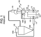
FIG. 1 , aroller mill 100 includes, for example, avessel 110 in which abowl assembly 112 is mounted. As shown inFIG. 1 , theexemplary roller mill 100 includegrinding rollers 118 each mounted on a suitably supportedjournal 120. Thejournals 120 are connected for rotation to adrive shaft 122 viasupport arms 121. Thegrinding rollers 118 interact with a grinding surface of thebowl assembly 112 to effect the grinding of material interposed therebetween. After being pulverized, the particles of material are thrown outwardly by centrifugal force whereby the particles of material are fed into a stream of air that is entering themill 100 via anannular manifold 117. The flow of air is through themill 100 is caused by afan 119 that is in communication with adischarge duct 123 of themill 100. Thefan 119 circulates air and pulverized fine particles entrained in the air into a separator 125 (e.g., a cyclone separator or bag house) that separates the fine particles and discharges them via anoutlet 125D. Circulating air that has most of the fine particles removed therefrom is discharged from theseparator 125 via theclean air port 125A and circulated back to theannular manifold 117. -
Prior art mills 100 typically employed aclassifier 130 in a classifier section of themill 100 located downstream of thegrinding rollers 118 and upstream of thefan 119 proximate thedischarge duct 123 of themill 100. The stream of air with the particles of material entrained therein flows into aclassifier 130 in which coarse particles of material are intended to be rejected from the air stream. These coarse material particles are then supposed to be returned to the grinding area for further pulverization, while the fine particles of material are supposed to be carried through themill 100 in the air stream, and exit along with the air. - As shown in
FIGS. 2 and3 oneprior art classifier 130 is known as a "whizzer separator" as disclosed inU.S. Patent No. 2,108,609 . One of theprior art classifiers 130 may be employed for the classification of the coarse particles or two or more of theprior art classifiers 130 may be employed in a series configuration. Theprior art classifier 130 includes a closedcentral disc 138 that is secured to arotatable shaft 130S. A plurality ofblades 139 extend radially outward from thedisc 138. Theblades 139 are beveled inwardly and upwardly thereby defining aninclined edge 140. Aconical deflector 141 is secured to awall 130W of the classifier section of themill 100. Theconical deflector 141 defines a outwardly and downwardly slopedsurface 141C. Theinclined edge 140 of theblades 139 rotate in close proximity to thesloped surface 141C. There is a gap G between thesloped surface 141C and theinclined edge 140. During operation of theprior art classifier 130, air and pulverized particles entrained in the air flow throughspaces 142 betweenadjacent blades 139. There is no flow through the central portion of theprior art separator 130 due to the presence of thedisc 138. - The applicant has conducted computational fluid dynamics (CFD) analysis on the
prior art classifiers 130 to determine particle velocity distributions upstream and downstream of the classifier and to determine particle size distribution. The CFD analysis demonstrated that the velocity profile of the particles upstream of theprior art classifier 130 were substantially straight and vertical with essentially no tangential velocity component or swirl. Such a velocity profile allow all sized particles, larger or small, to approach and enter theprior art classifier 130, without rejecting any of the larger particles. Thus, the separation mechanism for the prior art separator is via a "shutter effect" of the particles impinging theblades 139. For example, the substantially straight and vertical velocity profile may cause the larger particles to exit the classifier, if they hit theblades 139. - The CFD also demonstrated a strong vortex and recirculation zone downstream of the
blades 139 in theprior art classifier 130. Such a vortex and recirculation zone allows a substantial amount of the small particles (e.g., including 10 micron particles) that are supposed to exit the classifier to recirculate back into themill 100. The recirculation of the small particles back into themill 100 reduces the efficiency and output of theprior art classifier 130. - In addition, due to the close proximity of the
inclined edges 140 of theblades 139 to thesloped surface 141C of theconical deflector 141, theinclined edges 140 of theblades 139 and/or thesloped surface 141C of theconical deflector 141 tend to wear and decrease the effectiveness of theprior art classifier 130. The close proximity of theinclined edges 140 of theblades 139 to thesloped surface 141C of theconical deflector 141 creates alignment difficulties during assemble and operation. Furthermore, theprior art separator 130 is not configured to remove the heavier particles from themill 100, but instead merely returns them to the area of thegrinding rollers 118 for further grinding. This can cause operational problems with the mill as heavy and grit and hard particles such as raw sand and ground sand are maintained in themill 100. Moreover, theprior art separator 130 cannot distinguish or separate particles based on density of the particles. As a result, theprior art separator 130 cannot distinguish or separate grit from heavy material particles suitable to be re-ground. As a result, the prior art separators discharge a mixture that contains up to about 25 weight percent undesirable materials, such as sand, grit and other larger and high density particles, with the remainder (about 75 weight percent) being the material intended to be ground. Thus, 75 percent or more of the material discharged and rejected from theroller mill 100 as waste is the useable material intended to be DocumentUS5381968A discloses a roller mill system for grinding material comprising a vessel, which comprises a grinding zone having a grinding assembly configured for grinding the material into fine particles. - There is a need for an improved mill and separator system that can distinguish and separate undesirable particles from material intended to be ground and to achieve a discharge mixture that contains a higher percentage of the undesirable materials.
- In one aspect, there is disclosed herein a roller mill system for grinding material into fine particles. In one non-limiting exemplary embodiment, the roller mill system is a pendulum mill system. The roller mill system includes a vessel having a first inlet and a first outlet. The vessel is configured for flow of a gas from the first inlet to the first outlet. The vessel includes a grinding zone and a classifier zone located downstream of the grinding zone. The vessel may include a second inlet for feeding the material into the vessel. The grinding zone may be proximate to the first inlet. The grinding zone includes a grinding assembly configured for grinding the material into fine particles. The grinding zone also includes a rejects capture and discharge system that includes one or more discharge conduits for conveying rejects away from the vessel. The rejects capture and discharge system includes: 1) a collection trough located under the grinding assembly and in communication with one of the discharge conduits, for discharging rejects from the grinding zone; and/or 2) a turbine classifier mounted in the classifier zone. The turbine classifier is rotatable about a central axis. A second outlet is formed in a side wall of the classifier zone. The turbine classifier is configured to expel the rejects radially outward therefrom, through the second outlet and into another one of the discharge conduits.
- In one embodiment, the rejects capture and discharge system further includes a pressure control line in fluid communication with one or more of the discharge conduits. The pressure control line is configured to decrease pressure in the discharge conduit to a magnitude less than that in the grinding zone. In one embodiment, the pressure control line is in fluid communication with the classifier zone which is operated at a lower pressure than the grinding zone. In one embodiment, the pressure control line includes one or more valves therein for controlling pressure in the discharge conduit. In one embodiment, the pressure control line is fluid communication with a vacuum source.
- In one embodiment, the discharge conduit of the rejects capture and discharge system includes a conveyor for purging flow of the rejects out of the discharge conduit. For example, the conveyor of the rejects capture and discharge system may include a vibrator and/or a rotating screw.
- In one embodiment, the turbine classifier includes a plurality of vanes extending between an annular ring and a solid disc. The plurality of vanes are arranged radially outward from a central axis of the annular ring and solid disc. The solid disc blocks flow into a bottom portion of the turbine classifier and the annular ring defining an opening therein for discharge of fine ground particles therethrough.
- In one embodiment, the roller mill system includes a flow diversion flap moveably secured to the side wall of the roller mill at the second outlet and extends into the classifier zone. The flow diversion flap is configured to divert the rejects through the second outlet thereby exiting the classifier zone.
- In one embodiment, the roller mill system includes a duct secured to an outside portion of the side wall. The duct is positioned over the second outlet to convey the rejects outwardly from the classifier zone. In one embodiment, the duct has a backflow control damper positioned thereon for controlling flow of the rejects through the duct and to allow the fine particles to flow back into the classifier zone. In one embodiment, the duct include a plurality of perforated plates positioned in the duct to establish a uniform backflow of the fine particles back into the classifier zone.
- In one embodiment, the turbine classifier has a first diameter and the side wall of the classifier has a second diameter. The first diameter is about 40 to 80 percent of the second diameter. In one embodiment, the first diameter is about 55 to 65 percent of the second diameter. In one embodiment, the outside diameter D1 of the
turbine classifier 30 is about 60 percent of the inside diameter D2 of theside wall 10W. - The rejects capture and discharge system is configured to remove only those particles having a density or size greater than a predetermined magnitude.
-
-
FIG. 1 is a schematic diagram of a prior art roller mill, fan and cyclone separator; -
FIG. 2 is and enlarged cross sectional view of a classifier section of the prior art mill ofFIG. 1 ; -
FIG. 3 is top view of a portion of the prior art classifier ofFIG. 2 taken across line 3-3 ofFIG. 2 ; -
FIG. 4 is a schematic view of the roller mill system of the present invention having a collection trough located under the mill and a discharge conduit; -
FIG. 5 is a front view of the backflow control damper of the roller mill system ofFIG. 4 ; -
FIG. 6 is a top sectional view of the flow diversion flap ofFIG. 4 taken across line 6-6 ofFIG. 4 ; -
FIG. 7 is a side schematic view of the throw-out duct of the roller mill system ofFIG. 4 ; -
FIG. 8 is a side schematic view of another embodiment of the throw-out duct of the roller mill system ofFIG. 4 ; -
FIG. 9 is an enlarged view of the turbine classifier ofFIG. 4 ; -
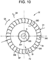
FIG. 10 is a sectional view of the turbine classifier taken across line 10-10 ofFIG. 9 ; -
FIG. 11 is a side perspective view of internal portions of the roller mill system ofFIG. 4 illustrating flow paths of the particles; and -
FIG. 12 is a top perspective view of internal portions of the roller mill system ofFIG. 4 illustrating flow paths of the particles. - As shown in
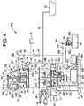
FIG. 4 , a roller mill system of the present invention is generally designated by thenumeral 1000. Theroller mill system 1000 shown and described inFIG. 4 is a pendulum mill that is referred to herein, by way of example, as one type of roller mill that can employ the present invention. However, the present invention is not limited in this regard as other types of roller mills may employ the present invention. Theroller mill system 1000 includes avessel 10 fixedly secured to aframe 11. Abowl assembly 12 is mounted in a grindingzone 10B located at a lower portion of thevessel 10. Theroller mill system 1000 includes a grindingassembly 14 mounted in the grindingzone 10B of thevessel 10 proximate thebowl assembly 12 for grinding a material into fine particles. The grindingassembly 14 includes a plurality ofrollers 18 each mounted on a suitably supportedjournal 20. Thejournals 20 are pivotally connected to asupport arms 21 viarespective pivot joints 21P. Thesupport arms 21 are connected for rotation to adrive shaft 22. Thedrive shaft 22 is supported for rotation relative to theframe 11 by a bearingassembly 22B. Thedrive shaft 22 is connected to aspeed control unit 22G (e.g., a gear box) via acoupling 22C. Amotor 22M is connected to thespeed control unit 22G via adrive coupling assembly 22D. Theframe 11, thespeed control unit 22G and themotor 22M are fixedly secured to a foundation F. In one embodiment, a plurality ofplows 41 that facilitate the direction of material to be ground into thebowl assembly 12. - The
vessel 10 has aturbine classifier 30 rotatably mounted in aclassifier zone 10C of thevessel 10 coaxially therewith. Theclassifier zone 10C is located downstream of the grindingassembly 14 and the grindingzone 10B of thevessel 10. Theturbine classifier 30 includes abody portion 30B that is fixedly secured to adrive shaft 30S that is mounted for rotation relative to thevessel 10, via a lower bearing 33L and anupper bearing 33U. Thedrive shaft 30S extends through an entrance opening 23E into thedischarge duct 23 proximate atop portion 10T of thevessel 10. Thedrive shaft 30S extends through an interior of thedischarge duct 23 and out through anopening 23T in thedischarge duct 23. A first drive disc 34 (e.g., a gear, pulley or sheave) is fixedly secured to a distal end of thedrive shaft 30S. Amotor 35 is fixedly mounted (i.e., relative to the foundation F) at a location adjacent to thedrive shaft 30S. Themotor 35 has amotor drive shaft 35X extending therefrom and rotatable relative to themotor 35 upon operation of themotor 35. In one embodiment, themotor 35 is controlled by acontrol unit 35C (e.g., a computer processor control system). Asecond drive disc 36 is fixedly secured to a distal end of thedrive shaft 35X. A linkage 37 (e.g., a belt or chain) drivingly couples thefirst drive disc 34 to thesecond drive disc 36 so that rotation of thedrive shaft 35X is transmitted to thedrive shaft 30S of theturbine classifier 30. - During operation, material to be pulverized is fed into the
vessel 10 via a feeder unit 29 (i.e., a second inlet into the vessel 10) and themotor 22M rotates thedrive coupling assembly 22D which causes rotation of gears (not shown) housed within thespeed control unit 22G. Thespeed control unit 22G is controlled by a control unit 31 (e.g., a computer processor control system) to create a predetermined and variable output speed of thedrive shaft 22. As a result, thesupport arms 21 rotate with theshaft 22 and cause thejournals 20 to swing radially outward in the direction indicated by the arrows Q1 about thepivot connections 21P, thereby causing therollers 18 to rolling engage a radially inward facing grindingsurface 12F of thebowl assembly 12. The grindingrollers 18 interact with the grindingsurface 12F of thebowl assembly 112 to effect the grinding of material interposed therebetween. After being pulverized, the particles of material are thrown outwardly by centrifugal force whereby the particles of material are fed into a stream of air as indicated by the arrow F1 that is entering thevessel 10 via an annular manifold 17 (i.e., a first inlet to the vessel) that is proximate the grindingzone 10B. The flow of air is through thevessel 10 is caused by a fan (not shown, but similar to thefan 119 illustrated inFIG. 1 ) that is in communication with a discharge duct 23 (i.e., a first outlet) of thevessel 10. The fan creates a pressure P2 in theannular manifold 17 and the grindingzone 10B; creates a lower pressure P1 in theclarifier zone 10C. The fan circulates air and pulverized fine particles entrained in the air into a separator (not shown but similar to theseparator 125 e.g., a cyclone separator or bag house illustrated inFIG. 1 ) that separates the fine particles and discharges them via an outlet. Circulating air that has most of the fine particles removed therefrom is discharged from the separator via a clean air port similar to theclean air port 125A ofFIG. 1 and circulated back to theannular manifold 17. - The
roller mill system 1000 includes a rejects capture and discharge system (e.g., subsystem) that includes a discharge conduit for conveying the rejects away from thevessel 10. As used herein, the term "rejects" means a discharge of a mixture of: 1) undesirable materials such as high density hard sand, silica and grit particles (e.g., having diameters greater than 150 microns, for example 200 to 250 microns and greater) that are not intended to be ground and other such particles that could damage theroller mill system 1000; along with 2) some of the material to be ground. The present invention is directed, in one aspect, to maximizing the percentage of undesirable materials in the rejects. - In one embodiment, the rejects capture and discharge system includes a
collection trough 51 located under the grindingassembly 14, for discharging rejects from the grindingzone 10B. In this embodiment, the discharge conduit includes: 1) a grindingzone discharge conduit 50 that is in communication with (e.g., connected to) thecollection trough 51; and 2) ahorizontal conveyor section 50H. The grindingzone discharge conduit 50 has avertical section 50V that has avalve 52 positioned therein for regulating (e.g., terminating, initiating and/or throttling flow) the flow of rejects through the grindingzone discharge conduit 50. The grindingzone discharge conduit 50 is connected to thehorizontal conveyor section 50H of the discharge conduit. Thehorizontal conveyor section 50H extends outwardly from thevertical section 50V. Thehorizontal conveyor section 50H includes a conveyor assist device such avibration generator 50G to urge or purge the rejects through the grindingzone discharge conduit 50. While, the conveyor assist device is described as being avibration generator 50G, the present invention is not limited in this regard as other configurations of the conveyor assist device may be employed including but not limited to a screw conveyor as shown inFIG. 4 . - An
outlet end 50Y of the grindingzone discharge conduit 50 has avalve 54 disposed therein (e.g., terminating, initiating and/or throttling flow) the flow of rejects through the grindingzone discharge conduit 50. In one embodiment, thevalve 54 is a double flapper type valve that has amotor actuator 54 thereon for controlling the position (e.g., open, closed or intermediate position) of thevalve 54. The rejects are discharged through thevalve 54 into a collecting vessel 55 such as an open top moveable rail car. - In one embodiment, the rejects capture and discharge system includes: 1) a
turbine classifier 30 rotatably mounted in theclassifier zone 10C for separating rejects from the material to be ground; and 2) an opening 61 (e.g., a second outlet) formed in aside wall 10W of theclassifier zone 10C, for collecting and discharging the rejects from theclassifier zone 10C. In this embodiment, the discharge conduit includes a classifierzone discharge conduit 70 that is in communication with theclassifier zone 10C via theopening 61. The turbine classifier is configured to expel the rejects radially outward therefrom, through theopening 61 and into the classifierzone discharge conduit 70. In one embodiment, the classifierzone discharge conduit 70 includes abranch connection 92 which is connected to anotherdischarge line 90 configured to discharge the rejects into another container 91 (e.g., a rail car). - In one embodiment, a rejects collection device 60 (e.g., a duct) is positioned over the
opening 61 and secured to an outside portion of theside wall 10W to convey rejects outwardly from theclassifier zone 10C as indicted by the arrow F3. As best shown inFIG. 6 , therejects collection device 60 includes a scoop 62 (e.g., a flap) that extends into theclassifier zone 10C through theopening 61 and a duct formedbody 63 that extends outwardly from theside wall 10W. Thescoop 62 is pivotable about ahinge 62P in the direction indicated by the arrow Q3. Anactuator 62A is in communication with thescoop 62 for positioning thescoop 62 at a predetermined position based on the amount, velocity and physical characteristics (e.g., density, particle size) of the rejects. - As shown in
FIGS. 5 and 6 therejects collection device 60 includes a backflow control damper 64 (e.g., slidable flap, valve, hinged door or the like) that is moveably positioned over anopening 65 in the duct formedbody 63, for controlling flow of the rejects through the duct and to allow the fine particles (e.g., those intended to be ground and used as a viable output of the mill) to flow back into the classifier zone by causing a backward flow of air through the opening and into theclassifier zone 10C, as indicated by the arrow F4 as illustrated inFIG. 4 . - As illustrated in
FIG. 7 , therejects collection device 60 includes a plurality of horizontalperforated plates 68H positioned in therejects collection device 60 to establish a uniform backflow of the fine particles back into theclassifier zone 10W as indicated by the arrow F4. While theperforated plates 68H are described as being horizontal, the present invention is not limited in this regard as other configurations may be employed including, but not limited to verticalperforated plates 68V as shown inFIG. 8 and combinations of the horizontalperforated plates 68H and verticalperforated plates 68V. - As illustrated in
FIG. 4 , in one embodiment, the rejects capture and discharge system further includes apressure control line 80 in fluid communication with theclassifier zone 10C and thehorizontal conveyor section 50H of the discharge conduit. Thepressure control line 80 is configured to decrease pressure in thehorizontal conveyor section 50H of the discharge conduit to a magnitude less than that in the grindingzone 10B as a result of the pressure P1 in theclassifier zone 10C being less than the pressure P2 in the grindingzone 10B and the pressure P3 in thehorizontal conveyor section 50H of the discharge conduit. For example, there is about a 10 inch water column pressure drop differential between P2 and PI. In one embodiment, thepressure control line 80 has avalve 81 positioned therein for controlling pressure in thehorizontal conveyor section 50H of the discharge conduit. In one embodiment, thehorizontal conveyor section 50H of the discharge conduit includes a clean outport 50C configured for being open to clear any rejects clogged or jammed in thehorizontal conveyor section 50H of the discharge conduit. While onevalve 81 is shown and described as being positioned in thepressure control line 80, the present invention is not limited in this regard as more than one valve and/or other pressure control devices (e.g., orifices) may be employed. In one embodiment, the pressure control line is fluid communication with avacuum source 82. - Referring to
FIGS. 9 and10 , theturbine classifier 30 includes a plurality ofvanes 39 extending (e.g., extending vertically) between and fixedly secured to anannular ring 38R and asolid disc 38D. Acentral hub 30H is secured to thesolid disc 38D and to thedrive shaft 30S of theturbine classifier 30. Thevanes 39 are arranged radially outward from a central axis A of theannular ring 38R andsolid disc 38D. Thesolid disc 38D blocks flow into a bottom portion 30Z of theturbine classifier 30. Theannular ring 38R hasopening 38E therein. Theopening 38E in theannular ring 38R is aligned with the entrance opening 23E of thedischarge duct 23 proximate thetop portion 10T of thevessel 10, for discharge of fine ground particles therethrough and into thedischarge duct 23. As shown inFIG. 10 , each of thevanes 39 has aradially extending portion 39F and circumferentially trailingsection 39B. There is aspace 39X between each adjacent pair ofvanes 39 through which essentially only the fine particles and air pass through as indicated by the arrows F2, as described herein. - As shown in
FIGS. 9 and10 , theturbine classifier 30 has an outside diameter D1. As shown inFIG. 4 , theside wall 10W of theclassifier zone 10C of thevessel 10 has an inside diameter D2. The outside diameter D1 of theturbine classifier 30 is about 40 to 80 percent of the inside diameter D2 of theside wall 10W, to allow adequate space for circulation of the fine particles while being close enough to allow the rejects to be discharged from theclassifier zone 10C. In one embodiment, the outside diameter D1 of theturbine classifier 30 is about 55 to 65 percent of the inside diameter D2 of theside wall 10W to allow a more than an adequate space for circulation of the fine particles while being close enough to allow the rejects to be discharged from theclassifier zone 10C. In one embodiment, the outside diameter D1 of theturbine classifier 30 is about 60 percent of the inside diameter D2 of theside wall 10W to allow a further more than an adequate space for circulation of the fine particles while being close enough to allow the rejects to be discharged from theclassifier zone 10C. In one embodiment, theturbine classifier 30 is spaced apart from theside wall 10W by a distance D3 of about 10 to 30 percent of the first diameter D1. The diameters D1 and D2, the spacing D3 and the above specified ratios thereof are based on CFD analysis to arrive at the specified ranges so that the rejects capture and discharge system is configured remove only those particles (e.g., sand, grit and other materials not intended to be ground) have a density and/or size greater than a predetermined magnitude, for example of a density greater than the fine particles or un-ground material. - As shown in
FIGS. 11 and12 , the Applicant's CFD analysis has shown that theturbine classifier 30 creates a strong swirling flow region upstream of and radially outward of theturbine classifier 30 as shown by the arrows Q5. The Applicant performed testing that demonstrated that the rejects included a mixture containing 40 to 60 weight percent of the undesirable materials (e.g., sand, silica, grit and other large and/or high density particles not intended to be ground). The rejects were discharged radially outward in the direction of the arrows Q6 by centrifugal force before they reach thevanes 39 of theturbine classifier 30. Only small particles may approach and penetrate through thespaces 39X between theblades 39, as indicted by the arrows F2 and exit from theturbine classifier 30 via thedischarge duct 23. This results in a discrete differentiation and separation of the rejects and large particles from the fine particles, for example the discharge through the grindingzone discharge conduit 50, thehorizontal conveyor section 50H and therejects collection device 60 discharges rejects mixtures having about 40 to 60 weight percent of the undesirable materials. The swirling of the flow and radially outward separation of the large and high density particles facilitates capture by thescoop 62 and discharge through therejects collection device 60. In one embodiment, discharge through therejects collection device 60 is about 6 to 8 percent of the total mass flow of material through theroller mill 1000. In one embodiment, the discharges rejects mixtures having about 40 to 60 weight percent of the undesirable materials was obtained by processing clay through theroller mill 1000, wherein the clay had a 6 wt% of silica. - In one embodiment, testing of the
roller mill system 1000 employing theclassifier 30 demonstrated that all of the small particles that penetrated through thespaces 39X between theblades 39 and exited theturbine classifier 30 via thedischarge duct 23 were 74 microns or less in size. In one embodiment, testing of theroller mill system 1000 employing theclassifier 30 demonstrated that 98 to 100 percent of the small particles that penetrated through thespaces 39X between theblades 39 and exited theturbine classifier 30 via thedischarge duct 23 were 44 microns or less in size. In one embodiment, testing of theroller mill system 1000 employing theclassifier 30 demonstrated that 92 to 98 percent of the small particles that penetrated through thespaces 39X between theblades 39 and exited theturbine classifier 30 via thedischarge duct 23 were 25 microns or less in size. - Although this invention has been shown and described with respect to the detailed embodiments thereof, it will be understood by those of skill in the art that various changes may be made and equivalents may be substituted for elements thereof without departing from the scope of the invention. In addition, modifications may be made to adapt a particular situation or material to the teachings of the invention without departing from the essential scope thereof. Therefore, it is intended that the invention not be limited to the particular embodiments disclosed in the above detailed description, but that the invention will include all embodiments falling within the scope of the appended claims.
Claims (14)
- A roller mill system (1000) for grinding material into fine particles, the roller mill system (1000) comprising:a vessel (10) having an inlet (17) and a first outlet (23), the vessel (10) being configured for flow of a gas from the inlet (17) to the first outlet (23), the vessel (10) comprising a grinding zone (10B) and a classifier zone (10C) located downstream of the grinding zone (10B);the grinding zone (10B) comprising a grinding assembly (14) configured for grinding the material into fine particles; anda rejects capture and discharge system comprising at least one discharge conduit (50) for conveying rejects away from the vessel (10), and at least one of:a collection trough (51) located under the grinding assembly (14) and in communication with the at least one discharge conduit (50), for discharging rejects from the grinding zone (10B); anda turbine classifier (30) mounted in the classifier zone (10C) and being rotatable about a central axis, a second outlet (61) formed in a side wall (10W) of the classifier zone (10C), the turbine classifier (30) being configured to expel the rejects radially outward therefrom, through the second outlet (61) and into the at least one discharge conduit (50).
- The roller mill system (1000) of claim 1, wherein the rejects capture and discharge system further comprises a pressure control line (80) in fluid communication with the at least one discharge conduit (50), the pressure control line (80) being configured to decrease pressure in the discharge conduit (50) to a magnitude less than that in the grinding zone (10B).
- The roller mill system (1000) of claim 2, wherein the pressure control line (80) is in fluid communication with the classifier zone (10C) which is operated at a lower pressure than the grinding zone (10B).
- The roller mill system of claim 2, wherein the pressure control line (80) includes at least one valve (81) therein for controlling pressure in the discharge conduit (50).
- The roller mill system of claim 2, wherein the discharge conduit (50) of the rejects capture and discharge system comprises a conveyor (50H) for urging flow of the rejects out of the discharge conduit (50).
- The roller mill system of claim 5, wherein the conveyor (50H) of the rejects capture and discharge system comprises at least one of a vibrator (50G) and a rotating screw.
- The roller mill system of claim 2, wherein the pressure control line (80) is fluid communication with a vacuum source (82).
- The roller mill system of claim 1, wherein the turbine classifier (30) comprises a plurality of vanes (39) extending between an annular ring (38R) and a solid disc (38D), the plurality of vanes (39) being arranged radially outward from a central axis (A) of the annular ring (38R) and solid disc (38D), the solid disc (38D) blocking flow into a bottom portion (30Z) of the turbine classifier (30) and the annular ring (38R) defining an opening (38E) therein for discharge of fine ground particles therethrough.
- The roller mill system of claim 1, further comprising a flow diversion flap (62) moveably secured to the side wall (10W) at the second outlet (61) and extending into the classifier zone (10C), the flow diversion flap (62) be configured to divert the rejects through the second outlet (61) thereby exiting the classifier zone (10C).
- The roller mill system (1000) of claim 1, further comprising a duct (63) secured to an outside portion of the side wall (10W), the duct being positioned over the second outlet (61) to convey the rejects outwardly from the classifier zone (10C).
- The roller mill system (1000) of claim 10, wherein the duct (63) comprises a backflow control damper (64) for controlling flow of the rejects through the duct (63) and to allow the fine particles to flow back into the classifier zone (10C).
- The roller mill system of claim 10, wherein the duct (63) comprises a plurality of perforated plates (68H) positioned in the duct (63) to establish a uniform backflow of the fine particles back into the classifier zone (10C).
- The roller mill system of claim 1, wherein the turbine classifier (30) has a first diameter (D1) and the side wall (10W) of the classifier (30) has a second diameter (D2), and the first diameter (D1) being about 40 to 80 percent of the second diameter (D2).
- The roller mill system (1000) of claim 1, wherein the rejects capture and discharge system is configured to remove only those particle having a density or sizes greater than a predetermined magnitude.
Applications Claiming Priority (2)
| Application Number | Priority Date | Filing Date | Title |
|---|---|---|---|
| US15/079,696 US10500592B2 (en) | 2016-03-24 | 2016-03-24 | Roller mill system with rejects removal system |
| PCT/US2017/023560 WO2017165503A1 (en) | 2016-03-24 | 2017-03-22 | Roller mill system with rejects removal system |
Publications (2)
| Publication Number | Publication Date |
|---|---|
| EP3433018A1 EP3433018A1 (en) | 2019-01-30 |
| EP3433018B1 true EP3433018B1 (en) | 2019-12-18 |
Family
ID=58464674
Family Applications (1)
| Application Number | Title | Priority Date | Filing Date |
|---|---|---|---|
| EP17715344.2A Revoked EP3433018B1 (en) | 2016-03-24 | 2017-03-22 | Roller mill system with rejects removal system |
Country Status (6)
| Country | Link |
|---|---|
| US (1) | US10500592B2 (en) |
| EP (1) | EP3433018B1 (en) |
| AU (1) | AU2017238142B2 (en) |
| ES (1) | ES2771224T3 (en) |
| MX (1) | MX2018011416A (en) |
| WO (1) | WO2017165503A1 (en) |
Families Citing this family (1)
| Publication number | Priority date | Publication date | Assignee | Title |
|---|---|---|---|---|
| CN108201941A (en) * | 2018-01-08 | 2018-06-26 | 广州腾耐计算机科技有限公司 | A kind of novel high polymer dyestuff milling device |
Citations (13)
| Publication number | Priority date | Publication date | Assignee | Title |
|---|---|---|---|---|
| US2754967A (en) | 1952-03-24 | 1956-07-17 | Microcyclomat Co | Centripetal classifier |
| US3951347A (en) | 1972-09-21 | 1976-04-20 | Polysius Ag | Apparatus for crushing material containing particles that are hard to pulverize |
| DD299997A7 (en) | 1988-08-01 | 1992-05-21 | Akad Wissenschaften Ddr | Classifier |
| US5279466A (en) | 1991-10-10 | 1994-01-18 | Williams Robert M | Isokinetic separator apparatus |
| US5330110A (en) | 1993-07-12 | 1994-07-19 | Williams Robert M | Apparatus for grinding material to a fineness grade |
| US5381968A (en) | 1991-07-23 | 1995-01-17 | Lohnherr; Ludger | Apparatus and method for the crushing of material for grinding of differing grain size |
| US5419499A (en) | 1991-02-15 | 1995-05-30 | Bourne; Ronald F. | Treatment of particulate material |
| DE19520325A1 (en) | 1994-06-03 | 1995-12-07 | Neuman & Esser Anlagenbau Gmbh | Deduster mill for chemicals and pharmaceuticals |
| WO2001043877A2 (en) | 1999-12-15 | 2001-06-21 | Hosokawa Micron Powder Systems | Apparatus for pulverizing and drying particulate material |
| US6820829B1 (en) | 2000-02-25 | 2004-11-23 | Exportech Company, Inc. | Method and apparatus for separating material |
| DE10352525A1 (en) | 2003-11-05 | 2005-06-16 | Neuman & Esser Gmbh Mahl- Und Sichtsysteme | cyclone separator |
| US20140076210A1 (en) | 2011-09-30 | 2014-03-20 | Mitsubishi Heavy Industries, Ltd | Biomass mill and biomass-coal mixed combustion system |
| US20150053800A1 (en) | 2012-02-08 | 2015-02-26 | Vicat | Plant for crushing mineral materials |
Family Cites Families (17)
| Publication number | Priority date | Publication date | Assignee | Title |
|---|---|---|---|---|
| US801572A (en) * | 1904-09-10 | 1905-10-10 | John Henry Davis | Pulverizing-mill. |
| US2108609A (en) * | 1935-04-15 | 1938-02-15 | Comb Eng Co Inc | Whizzer separator and mill |
| US2151253A (en) * | 1936-10-28 | 1939-03-21 | Jeffrey Mfg Co | Material handling method |
| US3770124A (en) | 1971-12-21 | 1973-11-06 | Combustion Eng | Swing back whizzer blades for mechanical air separator |
| US4597537A (en) * | 1982-09-14 | 1986-07-01 | Onoda Cement Company, Ltd. | Vertical mill |
| US5826807A (en) * | 1995-04-17 | 1998-10-27 | Csendes; Ernest | Method and apparatus for comminuting of solid particles |
| US5957300A (en) * | 1996-01-29 | 1999-09-28 | Sure Alloy Steel Corporation | Classifier vane for coal mills |
| AUPR635001A0 (en) * | 2001-07-13 | 2001-08-02 | Rmg Services Pty. Ltd. | Final additions to vortex comminution and drying system |
| DE10141414B4 (en) * | 2001-08-23 | 2004-03-04 | Loesche Gmbh | Roller mill, airflow roller mill, and method for grinding materials with magnetizable, in particular iron-containing components, for example slags |
| DE602004021551D1 (en) * | 2003-12-26 | 2009-07-30 | Canon Kk | Toner manufacturing process and device for surface treatment of toner particles |
| US7913851B2 (en) * | 2004-04-19 | 2011-03-29 | Jin-Hong Chang | Separator for grinding mill |
| US20050242008A1 (en) * | 2004-04-29 | 2005-11-03 | Peter Simpson | Material classifier |
| US7267293B2 (en) * | 2005-05-13 | 2007-09-11 | Alstom Technology Ltd | High efficiency bowl mill |
| US7665681B2 (en) * | 2007-11-14 | 2010-02-23 | Alstom Technology Ltd | Fine grinding roller mill |
| DE102011055762B4 (en) * | 2011-11-28 | 2014-08-28 | Maschinenfabrik Köppern GmbH & Co KG | Device for sifting granular material and grinding plant |
| DE102013101517A1 (en) * | 2013-02-15 | 2014-08-21 | Thyssenkrupp Resource Technologies Gmbh | Classifier and method for operating a classifier |
| WO2014153570A2 (en) * | 2013-03-15 | 2014-09-25 | Transtar Group, Ltd | New and improved system for processing various chemicals and materials |
-
2016
- 2016-03-24 US US15/079,696 patent/US10500592B2/en active Active
-
2017
- 2017-03-22 ES ES17715344T patent/ES2771224T3/en active Active
- 2017-03-22 WO PCT/US2017/023560 patent/WO2017165503A1/en active Application Filing
- 2017-03-22 EP EP17715344.2A patent/EP3433018B1/en not_active Revoked
- 2017-03-22 MX MX2018011416A patent/MX2018011416A/en unknown
- 2017-03-22 AU AU2017238142A patent/AU2017238142B2/en active Active
Patent Citations (14)
| Publication number | Priority date | Publication date | Assignee | Title |
|---|---|---|---|---|
| US2754967A (en) | 1952-03-24 | 1956-07-17 | Microcyclomat Co | Centripetal classifier |
| US3951347A (en) | 1972-09-21 | 1976-04-20 | Polysius Ag | Apparatus for crushing material containing particles that are hard to pulverize |
| DD299997A7 (en) | 1988-08-01 | 1992-05-21 | Akad Wissenschaften Ddr | Classifier |
| US5419499A (en) | 1991-02-15 | 1995-05-30 | Bourne; Ronald F. | Treatment of particulate material |
| US5381968A (en) | 1991-07-23 | 1995-01-17 | Lohnherr; Ludger | Apparatus and method for the crushing of material for grinding of differing grain size |
| US5279466A (en) | 1991-10-10 | 1994-01-18 | Williams Robert M | Isokinetic separator apparatus |
| US5330110A (en) | 1993-07-12 | 1994-07-19 | Williams Robert M | Apparatus for grinding material to a fineness grade |
| DE19520325A1 (en) | 1994-06-03 | 1995-12-07 | Neuman & Esser Anlagenbau Gmbh | Deduster mill for chemicals and pharmaceuticals |
| WO2001043877A2 (en) | 1999-12-15 | 2001-06-21 | Hosokawa Micron Powder Systems | Apparatus for pulverizing and drying particulate material |
| US6820829B1 (en) | 2000-02-25 | 2004-11-23 | Exportech Company, Inc. | Method and apparatus for separating material |
| US7124968B2 (en) | 2000-02-25 | 2006-10-24 | Exportech Company, Inc. | Method and apparatus for separating material |
| DE10352525A1 (en) | 2003-11-05 | 2005-06-16 | Neuman & Esser Gmbh Mahl- Und Sichtsysteme | cyclone separator |
| US20140076210A1 (en) | 2011-09-30 | 2014-03-20 | Mitsubishi Heavy Industries, Ltd | Biomass mill and biomass-coal mixed combustion system |
| US20150053800A1 (en) | 2012-02-08 | 2015-02-26 | Vicat | Plant for crushing mineral materials |
Non-Patent Citations (1)
| Title |
|---|
| STIESS, MATTHIAS: "Mechanische Verfahrenstechnik-Partikeltechnologie 1, 3. Auflage", 2009, SPRINGER VERLAG, article "6.4 Strömungsklassieren- Windsichten", pages: 1pp, 305 - 320, XP055769484 |
Also Published As
| Publication number | Publication date |
|---|---|
| EP3433018A1 (en) | 2019-01-30 |
| BR112018069169A2 (en) | 2019-01-29 |
| ES2771224T3 (en) | 2020-07-06 |
| AU2017238142B2 (en) | 2020-03-05 |
| MX2018011416A (en) | 2019-03-14 |
| WO2017165503A1 (en) | 2017-09-28 |
| AU2017238142A1 (en) | 2018-10-04 |
| US20170274387A1 (en) | 2017-09-28 |
| US10500592B2 (en) | 2019-12-10 |
Similar Documents
| Publication | Publication Date | Title |
|---|---|---|
| US4361290A (en) | Adjustable rotary crusher | |
| JP3800556B2 (en) | Attrition mill and method for selecting particles in slurry | |
| US7665681B2 (en) | Fine grinding roller mill | |
| US4694994A (en) | Roller mill | |
| EA012424B1 (en) | Drying mill and method of drying ground material | |
| KR0133172B1 (en) | Shredding and fludization drying apparatus | |
| CN107350162A (en) | Multi-product multi-stage classifier | |
| US20040084556A1 (en) | Hybrid turbine classifier | |
| US4749133A (en) | Apparatus for the pulverization and burning of solid fuels | |
| US4077574A (en) | Impact pulverizing mill with an attrition chamber and a vertical airflow classification chamber | |
| US4848677A (en) | Comminution/recovery ore mill | |
| EP3433018B1 (en) | Roller mill system with rejects removal system | |
| US4505435A (en) | Apparatus for removal of troublesome mineral matter from pulverized coal | |
| KR100801412B1 (en) | Crushing and classifying device | |
| CN210752975U (en) | Resin binder negative pressure grinding system for abrasive disc and brake pad | |
| KR20190077362A (en) | grinder | |
| MXPA97002608A (en) | Efficient production of gypsum calcinated by collection and classification of fine and | |
| CN208526863U (en) | A kind of micron ultra shifter | |
| GB2117667A (en) | Coal-milling plant with grit recirculation and separation of pyrite and mine-waste | |
| US1962455A (en) | Air separator | |
| US4037796A (en) | Rotary mill utilizing an impact reduction chamber and a vertical air flow classification chamber | |
| BR112018069169B1 (en) | ROLLER MILL SYSTEM | |
| JP2005152739A (en) | Lead bullet collecting system and method | |
| JP2650672B2 (en) | Material separator device | |
| JP2000157934A (en) | Pneumatic classifier |
Legal Events
| Date | Code | Title | Description |
|---|---|---|---|
| STAA | Information on the status of an ep patent application or granted ep patent |
Free format text: STATUS: UNKNOWN |
|
| STAA | Information on the status of an ep patent application or granted ep patent |
Free format text: STATUS: THE INTERNATIONAL PUBLICATION HAS BEEN MADE |
|
| PUAI | Public reference made under article 153(3) epc to a published international application that has entered the european phase |
Free format text: ORIGINAL CODE: 0009012 |
|
| STAA | Information on the status of an ep patent application or granted ep patent |
Free format text: STATUS: REQUEST FOR EXAMINATION WAS MADE |
|
| 17P | Request for examination filed |
Effective date: 20181012 |
|
| AK | Designated contracting states |
Kind code of ref document: A1 Designated state(s): AL AT BE BG CH CY CZ DE DK EE ES FI FR GB GR HR HU IE IS IT LI LT LU LV MC MK MT NL NO PL PT RO RS SE SI SK SM TR |
|
| AX | Request for extension of the european patent |
Extension state: BA ME |
|
| DAV | Request for validation of the european patent (deleted) | ||
| DAX | Request for extension of the european patent (deleted) | ||
| REG | Reference to a national code |
Ref country code: DE Ref legal event code: R079 Ref document number: 602017009910 Country of ref document: DE Free format text: PREVIOUS MAIN CLASS: B02C0015020000 Ipc: B02C0015040000 |
|
| GRAP | Despatch of communication of intention to grant a patent |
Free format text: ORIGINAL CODE: EPIDOSNIGR1 |
|
| STAA | Information on the status of an ep patent application or granted ep patent |
Free format text: STATUS: GRANT OF PATENT IS INTENDED |
|
| RIC1 | Information provided on ipc code assigned before grant |
Ipc: B02C 15/04 20060101AFI20190710BHEP Ipc: B02C 15/02 20060101ALI20190710BHEP Ipc: B02C 15/00 20060101ALI20190710BHEP Ipc: B02C 23/30 20060101ALI20190710BHEP |
|
| INTG | Intention to grant announced |
Effective date: 20190809 |
|
| GRAS | Grant fee paid |
Free format text: ORIGINAL CODE: EPIDOSNIGR3 |
|
| RAP1 | Party data changed (applicant data changed or rights of an application transferred) |
Owner name: SCHENCK PROCESS LLC |
|
| GRAA | (expected) grant |
Free format text: ORIGINAL CODE: 0009210 |
|
| STAA | Information on the status of an ep patent application or granted ep patent |
Free format text: STATUS: THE PATENT HAS BEEN GRANTED |
|
| AK | Designated contracting states |
Kind code of ref document: B1 Designated state(s): AL AT BE BG CH CY CZ DE DK EE ES FI FR GB GR HR HU IE IS IT LI LT LU LV MC MK MT NL NO PL PT RO RS SE SI SK SM TR |
|
| REG | Reference to a national code |
Ref country code: CH Ref legal event code: EP |
|
| REG | Reference to a national code |
Ref country code: IE Ref legal event code: FG4D |
|
| REG | Reference to a national code |
Ref country code: DE Ref legal event code: R096 Ref document number: 602017009910 Country of ref document: DE |
|
| REG | Reference to a national code |
Ref country code: AT Ref legal event code: REF Ref document number: 1214003 Country of ref document: AT Kind code of ref document: T Effective date: 20200115 |
|
| REG | Reference to a national code |
Ref country code: NL Ref legal event code: MP Effective date: 20191218 |
|
| PG25 | Lapsed in a contracting state [announced via postgrant information from national office to epo] |
Ref country code: FI Free format text: LAPSE BECAUSE OF FAILURE TO SUBMIT A TRANSLATION OF THE DESCRIPTION OR TO PAY THE FEE WITHIN THE PRESCRIBED TIME-LIMIT Effective date: 20191218 Ref country code: NO Free format text: LAPSE BECAUSE OF FAILURE TO SUBMIT A TRANSLATION OF THE DESCRIPTION OR TO PAY THE FEE WITHIN THE PRESCRIBED TIME-LIMIT Effective date: 20200318 Ref country code: LT Free format text: LAPSE BECAUSE OF FAILURE TO SUBMIT A TRANSLATION OF THE DESCRIPTION OR TO PAY THE FEE WITHIN THE PRESCRIBED TIME-LIMIT Effective date: 20191218 Ref country code: BG Free format text: LAPSE BECAUSE OF FAILURE TO SUBMIT A TRANSLATION OF THE DESCRIPTION OR TO PAY THE FEE WITHIN THE PRESCRIBED TIME-LIMIT Effective date: 20200318 Ref country code: SE Free format text: LAPSE BECAUSE OF FAILURE TO SUBMIT A TRANSLATION OF THE DESCRIPTION OR TO PAY THE FEE WITHIN THE PRESCRIBED TIME-LIMIT Effective date: 20191218 Ref country code: LV Free format text: LAPSE BECAUSE OF FAILURE TO SUBMIT A TRANSLATION OF THE DESCRIPTION OR TO PAY THE FEE WITHIN THE PRESCRIBED TIME-LIMIT Effective date: 20191218 Ref country code: GR Free format text: LAPSE BECAUSE OF FAILURE TO SUBMIT A TRANSLATION OF THE DESCRIPTION OR TO PAY THE FEE WITHIN THE PRESCRIBED TIME-LIMIT Effective date: 20200319 |
|
| REG | Reference to a national code |
Ref country code: LT Ref legal event code: MG4D |
|
| PG25 | Lapsed in a contracting state [announced via postgrant information from national office to epo] |
Ref country code: HR Free format text: LAPSE BECAUSE OF FAILURE TO SUBMIT A TRANSLATION OF THE DESCRIPTION OR TO PAY THE FEE WITHIN THE PRESCRIBED TIME-LIMIT Effective date: 20191218 Ref country code: RS Free format text: LAPSE BECAUSE OF FAILURE TO SUBMIT A TRANSLATION OF THE DESCRIPTION OR TO PAY THE FEE WITHIN THE PRESCRIBED TIME-LIMIT Effective date: 20191218 |
|
| PG25 | Lapsed in a contracting state [announced via postgrant information from national office to epo] |
Ref country code: AL Free format text: LAPSE BECAUSE OF FAILURE TO SUBMIT A TRANSLATION OF THE DESCRIPTION OR TO PAY THE FEE WITHIN THE PRESCRIBED TIME-LIMIT Effective date: 20191218 |
|
| REG | Reference to a national code |
Ref country code: ES Ref legal event code: FG2A Ref document number: 2771224 Country of ref document: ES Kind code of ref document: T3 Effective date: 20200706 |
|
| PG25 | Lapsed in a contracting state [announced via postgrant information from national office to epo] |
Ref country code: EE Free format text: LAPSE BECAUSE OF FAILURE TO SUBMIT A TRANSLATION OF THE DESCRIPTION OR TO PAY THE FEE WITHIN THE PRESCRIBED TIME-LIMIT Effective date: 20191218 Ref country code: NL Free format text: LAPSE BECAUSE OF FAILURE TO SUBMIT A TRANSLATION OF THE DESCRIPTION OR TO PAY THE FEE WITHIN THE PRESCRIBED TIME-LIMIT Effective date: 20191218 Ref country code: RO Free format text: LAPSE BECAUSE OF FAILURE TO SUBMIT A TRANSLATION OF THE DESCRIPTION OR TO PAY THE FEE WITHIN THE PRESCRIBED TIME-LIMIT Effective date: 20191218 Ref country code: CZ Free format text: LAPSE BECAUSE OF FAILURE TO SUBMIT A TRANSLATION OF THE DESCRIPTION OR TO PAY THE FEE WITHIN THE PRESCRIBED TIME-LIMIT Effective date: 20191218 Ref country code: PT Free format text: LAPSE BECAUSE OF FAILURE TO SUBMIT A TRANSLATION OF THE DESCRIPTION OR TO PAY THE FEE WITHIN THE PRESCRIBED TIME-LIMIT Effective date: 20200513 |
|
| PG25 | Lapsed in a contracting state [announced via postgrant information from national office to epo] |
Ref country code: SM Free format text: LAPSE BECAUSE OF FAILURE TO SUBMIT A TRANSLATION OF THE DESCRIPTION OR TO PAY THE FEE WITHIN THE PRESCRIBED TIME-LIMIT Effective date: 20191218 Ref country code: IS Free format text: LAPSE BECAUSE OF FAILURE TO SUBMIT A TRANSLATION OF THE DESCRIPTION OR TO PAY THE FEE WITHIN THE PRESCRIBED TIME-LIMIT Effective date: 20200418 Ref country code: SK Free format text: LAPSE BECAUSE OF FAILURE TO SUBMIT A TRANSLATION OF THE DESCRIPTION OR TO PAY THE FEE WITHIN THE PRESCRIBED TIME-LIMIT Effective date: 20191218 |
|
| REG | Reference to a national code |
Ref country code: DE Ref legal event code: R026 Ref document number: 602017009910 Country of ref document: DE |
|
| PLBI | Opposition filed |
Free format text: ORIGINAL CODE: 0009260 |
|
| PLAX | Notice of opposition and request to file observation + time limit sent |
Free format text: ORIGINAL CODE: EPIDOSNOBS2 |
|
| REG | Reference to a national code |
Ref country code: AT Ref legal event code: MK05 Ref document number: 1214003 Country of ref document: AT Kind code of ref document: T Effective date: 20191218 |
|
| 26 | Opposition filed |
Opponent name: NEUMAN & ESSER PROCESS TECHNOLOGY GMBH Effective date: 20200918 |
|
| PG25 | Lapsed in a contracting state [announced via postgrant information from national office to epo] |
Ref country code: DK Free format text: LAPSE BECAUSE OF FAILURE TO SUBMIT A TRANSLATION OF THE DESCRIPTION OR TO PAY THE FEE WITHIN THE PRESCRIBED TIME-LIMIT Effective date: 20191218 Ref country code: MC Free format text: LAPSE BECAUSE OF FAILURE TO SUBMIT A TRANSLATION OF THE DESCRIPTION OR TO PAY THE FEE WITHIN THE PRESCRIBED TIME-LIMIT Effective date: 20191218 |
|
| REG | Reference to a national code |
Ref country code: CH Ref legal event code: PL |
|
| PG25 | Lapsed in a contracting state [announced via postgrant information from national office to epo] |
Ref country code: SI Free format text: LAPSE BECAUSE OF FAILURE TO SUBMIT A TRANSLATION OF THE DESCRIPTION OR TO PAY THE FEE WITHIN THE PRESCRIBED TIME-LIMIT Effective date: 20191218 Ref country code: AT Free format text: LAPSE BECAUSE OF FAILURE TO SUBMIT A TRANSLATION OF THE DESCRIPTION OR TO PAY THE FEE WITHIN THE PRESCRIBED TIME-LIMIT Effective date: 20191218 |
|
| REG | Reference to a national code |
Ref country code: BE Ref legal event code: MM Effective date: 20200331 |
|
| PG25 | Lapsed in a contracting state [announced via postgrant information from national office to epo] |
Ref country code: LU Free format text: LAPSE BECAUSE OF NON-PAYMENT OF DUE FEES Effective date: 20200322 |
|
| PG25 | Lapsed in a contracting state [announced via postgrant information from national office to epo] |
Ref country code: IE Free format text: LAPSE BECAUSE OF NON-PAYMENT OF DUE FEES Effective date: 20200322 Ref country code: CH Free format text: LAPSE BECAUSE OF NON-PAYMENT OF DUE FEES Effective date: 20200331 Ref country code: IT Free format text: LAPSE BECAUSE OF FAILURE TO SUBMIT A TRANSLATION OF THE DESCRIPTION OR TO PAY THE FEE WITHIN THE PRESCRIBED TIME-LIMIT Effective date: 20191218 Ref country code: LI Free format text: LAPSE BECAUSE OF NON-PAYMENT OF DUE FEES Effective date: 20200331 |
|
| RDAF | Communication despatched that patent is revoked |
Free format text: ORIGINAL CODE: EPIDOSNREV1 |
|
| REG | Reference to a national code |
Ref country code: DE Ref legal event code: R064 Ref document number: 602017009910 Country of ref document: DE Ref country code: DE Ref legal event code: R103 Ref document number: 602017009910 Country of ref document: DE |
|
| PG25 | Lapsed in a contracting state [announced via postgrant information from national office to epo] |
Ref country code: PL Free format text: LAPSE BECAUSE OF FAILURE TO SUBMIT A TRANSLATION OF THE DESCRIPTION OR TO PAY THE FEE WITHIN THE PRESCRIBED TIME-LIMIT Effective date: 20191218 Ref country code: BE Free format text: LAPSE BECAUSE OF NON-PAYMENT OF DUE FEES Effective date: 20200331 |
|
| PLBB | Reply of patent proprietor to notice(s) of opposition received |
Free format text: ORIGINAL CODE: EPIDOSNOBS3 |
|
| PGFP | Annual fee paid to national office [announced via postgrant information from national office to epo] |
Ref country code: FR Payment date: 20210324 Year of fee payment: 5 |
|
| RDAG | Patent revoked |
Free format text: ORIGINAL CODE: 0009271 |
|
| STAA | Information on the status of an ep patent application or granted ep patent |
Free format text: STATUS: PATENT REVOKED |
|
| PGFP | Annual fee paid to national office [announced via postgrant information from national office to epo] |
Ref country code: GB Payment date: 20210324 Year of fee payment: 5 Ref country code: DE Payment date: 20210319 Year of fee payment: 5 |
|
| REG | Reference to a national code |
Ref country code: FI Ref legal event code: MGE |
|
| 27W | Patent revoked |
Effective date: 20210214 |
|
| GBPR | Gb: patent revoked under art. 102 of the ep convention designating the uk as contracting state |
Effective date: 20210214 |
|
| PGFP | Annual fee paid to national office [announced via postgrant information from national office to epo] |
Ref country code: ES Payment date: 20210525 Year of fee payment: 5 |
|
| PG25 | Lapsed in a contracting state [announced via postgrant information from national office to epo] |
Ref country code: TR Free format text: LAPSE BECAUSE OF FAILURE TO SUBMIT A TRANSLATION OF THE DESCRIPTION OR TO PAY THE FEE WITHIN THE PRESCRIBED TIME-LIMIT Effective date: 20191218 |
|
| PG25 | Lapsed in a contracting state [announced via postgrant information from national office to epo] |
Ref country code: MK Free format text: LAPSE BECAUSE OF FAILURE TO SUBMIT A TRANSLATION OF THE DESCRIPTION OR TO PAY THE FEE WITHIN THE PRESCRIBED TIME-LIMIT Effective date: 20191218 |