EP3432469B1 - Fotovoltaisches ökologisches gewächshaus und fotovoltaikmoduleinheit davon - Google Patents
Fotovoltaisches ökologisches gewächshaus und fotovoltaikmoduleinheit davon Download PDFInfo
- Publication number
- EP3432469B1 EP3432469B1 EP16894010.4A EP16894010A EP3432469B1 EP 3432469 B1 EP3432469 B1 EP 3432469B1 EP 16894010 A EP16894010 A EP 16894010A EP 3432469 B1 EP3432469 B1 EP 3432469B1
- Authority
- EP
- European Patent Office
- Prior art keywords
- support
- photovoltaic module
- photovoltaic
- contact point
- disposed
- Prior art date
- Legal status (The legal status is an assumption and is not a legal conclusion. Google has not performed a legal analysis and makes no representation as to the accuracy of the status listed.)
- Active
Links
Images




Classifications
-
- H—ELECTRICITY
- H02—GENERATION; CONVERSION OR DISTRIBUTION OF ELECTRIC POWER
- H02S—GENERATION OF ELECTRIC POWER BY CONVERSION OF INFRARED RADIATION, VISIBLE LIGHT OR ULTRAVIOLET LIGHT, e.g. USING PHOTOVOLTAIC [PV] MODULES
- H02S20/00—Supporting structures for PV modules
- H02S20/20—Supporting structures directly fixed to an immovable object
-
- A—HUMAN NECESSITIES
- A01—AGRICULTURE; FORESTRY; ANIMAL HUSBANDRY; HUNTING; TRAPPING; FISHING
- A01G—HORTICULTURE; CULTIVATION OF VEGETABLES, FLOWERS, RICE, FRUIT, VINES, HOPS OR SEAWEED; FORESTRY; WATERING
- A01G9/00—Cultivation in receptacles, forcing-frames or greenhouses; Edging for beds, lawn or the like
- A01G9/14—Greenhouses
-
- H—ELECTRICITY
- H02—GENERATION; CONVERSION OR DISTRIBUTION OF ELECTRIC POWER
- H02S—GENERATION OF ELECTRIC POWER BY CONVERSION OF INFRARED RADIATION, VISIBLE LIGHT OR ULTRAVIOLET LIGHT, e.g. USING PHOTOVOLTAIC [PV] MODULES
- H02S20/00—Supporting structures for PV modules
- H02S20/30—Supporting structures being movable or adjustable, e.g. for angle adjustment
-
- F—MECHANICAL ENGINEERING; LIGHTING; HEATING; WEAPONS; BLASTING
- F24—HEATING; RANGES; VENTILATING
- F24S—SOLAR HEAT COLLECTORS; SOLAR HEAT SYSTEMS
- F24S25/00—Arrangement of stationary mountings or supports for solar heat collector modules
- F24S25/10—Arrangement of stationary mountings or supports for solar heat collector modules extending in directions away from a supporting surface
- F24S25/13—Profile arrangements, e.g. trusses
-
- F—MECHANICAL ENGINEERING; LIGHTING; HEATING; WEAPONS; BLASTING
- F24—HEATING; RANGES; VENTILATING
- F24S—SOLAR HEAT COLLECTORS; SOLAR HEAT SYSTEMS
- F24S30/00—Arrangements for moving or orienting solar heat collector modules
- F24S30/20—Arrangements for moving or orienting solar heat collector modules for linear movement
-
- H—ELECTRICITY
- H02—GENERATION; CONVERSION OR DISTRIBUTION OF ELECTRIC POWER
- H02S—GENERATION OF ELECTRIC POWER BY CONVERSION OF INFRARED RADIATION, VISIBLE LIGHT OR ULTRAVIOLET LIGHT, e.g. USING PHOTOVOLTAIC [PV] MODULES
- H02S10/00—PV power plants; Combinations of PV energy systems with other systems for the generation of electric power
- H02S10/40—Mobile PV generator systems
-
- F—MECHANICAL ENGINEERING; LIGHTING; HEATING; WEAPONS; BLASTING
- F24—HEATING; RANGES; VENTILATING
- F24S—SOLAR HEAT COLLECTORS; SOLAR HEAT SYSTEMS
- F24S25/00—Arrangement of stationary mountings or supports for solar heat collector modules
- F24S2025/01—Special support components; Methods of use
- F24S2025/012—Foldable support elements
-
- F—MECHANICAL ENGINEERING; LIGHTING; HEATING; WEAPONS; BLASTING
- F24—HEATING; RANGES; VENTILATING
- F24S—SOLAR HEAT COLLECTORS; SOLAR HEAT SYSTEMS
- F24S30/00—Arrangements for moving or orienting solar heat collector modules
- F24S2030/10—Special components
- F24S2030/11—Driving means
- F24S2030/115—Linear actuators, e.g. pneumatic cylinders
-
- Y—GENERAL TAGGING OF NEW TECHNOLOGICAL DEVELOPMENTS; GENERAL TAGGING OF CROSS-SECTIONAL TECHNOLOGIES SPANNING OVER SEVERAL SECTIONS OF THE IPC; TECHNICAL SUBJECTS COVERED BY FORMER USPC CROSS-REFERENCE ART COLLECTIONS [XRACs] AND DIGESTS
- Y02—TECHNOLOGIES OR APPLICATIONS FOR MITIGATION OR ADAPTATION AGAINST CLIMATE CHANGE
- Y02E—REDUCTION OF GREENHOUSE GAS [GHG] EMISSIONS, RELATED TO ENERGY GENERATION, TRANSMISSION OR DISTRIBUTION
- Y02E10/00—Energy generation through renewable energy sources
- Y02E10/40—Solar thermal energy, e.g. solar towers
- Y02E10/47—Mountings or tracking
-
- Y—GENERAL TAGGING OF NEW TECHNOLOGICAL DEVELOPMENTS; GENERAL TAGGING OF CROSS-SECTIONAL TECHNOLOGIES SPANNING OVER SEVERAL SECTIONS OF THE IPC; TECHNICAL SUBJECTS COVERED BY FORMER USPC CROSS-REFERENCE ART COLLECTIONS [XRACs] AND DIGESTS
- Y02—TECHNOLOGIES OR APPLICATIONS FOR MITIGATION OR ADAPTATION AGAINST CLIMATE CHANGE
- Y02E—REDUCTION OF GREENHOUSE GAS [GHG] EMISSIONS, RELATED TO ENERGY GENERATION, TRANSMISSION OR DISTRIBUTION
- Y02E10/00—Energy generation through renewable energy sources
- Y02E10/50—Photovoltaic [PV] energy
Definitions
- the present invention relates to the field of photovoltaic ecology, in particular to a photovoltaic ecological greenhouse and its photovoltaic module unit.
- the number of photovoltaic module units on a photovoltaic ecological greenhouse can be adjusted accordingly, and the excess photovoltaic module units can be stored into a warehouse or the insufficient photovoltaic module units can be transferred from the warehouse.
- WO2014/168464 A2 relates to a device which comprises two platforms of a photovoltaic panel pivotably linked about the shaft, which are raised vertically by a rod cylinder secured to the shaft and four wheels allowing the two platforms to slide on rails, thus creating an angle of inclination of the platforms.
- US2014/284292 A1 discloses photovoltaic panel support system including a surface frame and a support frame.
- the surface frame may be mounted to a surface.
- the support frame may be attached to the surface frame and may support photovoltaic panels.
- the panel may further include a plurality of vertical posts.
- Each vertical post may include a top end and a bottom end. The top end may connect with the support frame and the bottom end is supported by at least one of the surface frame and the surface. At least a portion of the plurality of vertical posts includes a wheel on the bottom end.
- the present invention provides a photovoltaic ecological greenhouse, and a support frame thereof that is foldable and stackable for storage, thus saving the warehouse space.
- a photovoltaic module unit for a photovoltaic ecological greenhouse comprises a support for mounting on a supporting frame of a photovoltaic power station or a photovoltaic ecological greenhouse; and a photovoltaic module provided on said support, wherein the support comprises a bottom support and a vertical telescopic support provided on a side of the bottom support, and a side of the photovoltaic module and an upper end of the telescopic support are slidably and rotatably connected, and the other side of the photovoltaic module and the other side of the bottom support are rotatably connected.
- the photovoltaic module unit further comprises a conveying mechanism, the conveying mechanism is provided with a first contact point for contact and electrical connection with the supporting frame, and the first contact point is provided on the lower part of the support and is electrically connected with the photovoltaic module to output the electric energy of the photovoltaic module.
- the telescopic support comprises a support telescoping sleeve fixedly connected to the bottom support, a support telescoping rod vertically slidably connected to the support telescoping sleeve, and a hydraulic drive mechanism provided between the support telescoping sleeve and the support telescoping rod.
- the support telescoping rod is connected with the photovoltaic module.
- the support telescoping rod is connected with the photovoltaic module through a second-stage support telescoping rod, the second-stage support telescoping rod is connected with the support telescoping rod in a vertically slidable manner, and a second-stage hydraulic drive mechanism is disposed between the second-stage support telescoping rod and the support telescoping rod.
- the hydraulic drive mechanism is a hydraulic oil cylinder.
- the conveying mechanism further comprises a hollow insulating shell fixedly connected to the lower part of the support, and a metal contact movably disposed in the insulating shell, the first contact point is formed on one end of the metal contact, the other end of the metal contact is electrically connected with the photovoltaic module through a first conducting wire, a through hole for enabling the first contact point to protrude is provided on one end of the insulating shell, a through hole for enabling the first conducting wire to protrude is provided on the other end of the insulating shell, and an elastic member for providing an elastic force for enabling the contact to protrude is disposed between the insulating shell and the metal contact.
- a photovoltaic ecological greenhouse comprises a supporting frame disposed on the ground to form a support, and a plurality of photovoltaic module units disposed on the supporting frame, and the photovoltaic module unit is any of the above-mentioned photovoltaic module units.
- the supporting frame is provided with a frame for mounting the photovoltaic module unit, and the bottom support of the photovoltaic module unit is slidably and detachably disposed on the frame.
- the frame is provided with guide rails, a guide groove is provided on the guide rail, a slider is disposed on the lower part of the bottom support, and the slider is slidably inserted into the guide groove.
- the conveying mechanism comprises a second contact point provided on the guide rail, the second contact point is electrically connected with a second conducting wire, a sliding slot is provided on the guide rail, and the second contact point is provided on the bottom of the sliding slot, and the conveying mechanism further comprises a hollow insulating shell fixedly disposed on the lower part of the support, and a metal contact movably disposed in the insulating shell, the first contact point is formed on one end of the metal contact, the other end of the metal contact is electrically connected with the first conducting wire, a through hole for enabling the first contact point to protrude is formed at one end of the insulating shell, a through hole for enabling the first conducting wire to protrude is formed at the other end of the insulating shell, an elastic member for driving the metal contact to move is disposed between the metal contact and the insulating shell, and when the photovoltaic module unit is installed in place, the metal contact is inserted into the sliding slot, and the first contact point comes into contact and electrical connection with the second contact point.
- the present invention has the following advantages: the telescopic support is capable of vertically extending and shrinking, when the telescopic support retracts downward, a side of the photovoltaic module descends and becomes flush with the other side, that is, the photovoltaic module lies down, so that the photovoltaic module units can be folded and can be stacked mutually during the storage, thereby reducing the storage volume and saving the warehouse space.
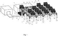
- a photovoltaic ecological greenhouse comprises a supporting frame 1, photovoltaic module units 2 disposed on an upper end of the supporting frame 1, a module stacking warehouse 3 disposed beside the supporting frame 1, a maintenance warehouse 4 disposed beside the module stacking warehouse 3, a transmission device 5 for transporting the photovoltaic module units 2, and a control mechanism for adjusting the number of the photovoltaic module units 2.
- the supporting frame 1 comprises a plurality of columns 11 arranged in an array, and a frame fixedly connected to the upper ends of all columns 11.
- the column 11 is of a telescoping rod type, that is, each column 11 comprises an column telescoping sleeve 111, a column telescoping rod 112 connected with the column telescoping sleeve 111 in a vertically slidable manner, and a hydraulic drive mechanism 113 (such as a hydraulic oil cylinder or the like) disposed between the column telescoping sleeve 111 and the column telescoping rod 112 and used for driving the column telescoping rod 112 to slide up and down relative to the column telescoping sleeve 111.
- a hydraulic drive mechanism 113 such as a hydraulic oil cylinder or the like
- the frame comprises a plurality of transverse guide rails 12 arranged along the longitudinal direction at equal intervals and extending along the transverse direction respectively, and a plurality of longitudinal guide rails 13 arranged along the transverse direction at equal intervals and extending along the longitudinal direction respectively, the plurality of transverse guide rails 12 and the plurality of longitudinal guide rails 13 intersect each other to form a plurality of rectangular frame units arranged in an array, some of the frame units are used as module placement positions 14 for installing the photovoltaic module, the other frame units are used as conveying units 15 constituting a conveying channel of the photovoltaic module unit, and any two adjacent module placement positions 14 are spaced by a conveying unit 15.
- connection mechanism for mechanical connection and/or power transmission with the photovoltaic module unit is disposed on the module placement position 14.
- the photovoltaic module unit 2 comprises a support 21 and a photovoltaic module 20 disposed on an upper end of the support 21.
- the photovoltaic module 20 is a double-glass photovoltaic module, the main function of the photovoltaic module 20 is that solar cells of the photovoltaic module 20 convert solar energy into electric energy after being irradiated by the sunlight, and the electric energy is conveyed by a junction box of the photovoltaic module.
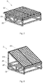
- the support 21 comprises a bottom support 22 and a telescopic support 23 disposed on the bottom support 22, the telescopic support 23 is disposed on a side of the bottom support 22, a side of the photovoltaic module 20 is connected with one side of the telescopic support 23, and the other side of the photovoltaic module 20 is connected with the other side of the bottom support 22.
- the bottom support 22 is in slide fit connection with the frame.
- a transverse guide groove 120 extending along the transverse direction is formed on the transverse guide rail 12
- a longitudinal guide groove 130 extending along the longitudinal direction is formed on the longitudinal guide rail 13; and at the intersection of the transverse guide rail 12 and the longitudinal guide rail 13, that is, at the vertex of each frame unit, the transverse guide groove 120 and the longitudinal guide groove 130 are in communication with each other.
- the bottom of the bottom support 22 is provided with a slider 220 cooperating with the transverse guide groove 120 and the longitudinal guide groove 130, the slider 220 is slidably inserted into the transverse guide groove 120 or the longitudinal guide groove 130, and can enter the longitudinal channel 130 or the transverse channel 120 from the transverse channel 120 or the longitudinal channel 130 at the intersection of the transverse guide rail 12 and the longitudinal guide rail 13.
- the telescopic support 23 comprises a support telescoping sleeve 231, a support telescoping rod 232 connected with the support telescoping sleeve 231 in a vertically slidable manner, and a hydraulic drive mechanism 233 (such as a hydraulic oil cylinder or the like) disposed between the support telescoping sleeve 231 and the support telescoping rod 232, and the hydraulic drive mechanism 233 drives the support telescoping rod 232 to slide up and down relative to the support telescoping sleeve 231.
- a hydraulic drive mechanism 233 such as a hydraulic oil cylinder or the like
- the lower end of the support telescoping sleeve 231 is fixedly connected with the bottom support 22, the upper end of the support telescoping rod 232 is movably connected with the frame of the photovoltaic module 20, particularly, the upper end of the support telescoping rod 232 is in slidable and rotatable connection with the frame of the photovoltaic module 20, the other side of the bottom support 21 is in rotatable connection (for example, pivotal connection or the like) with the frame of the photovoltaic module 20.
- the support telescoping rod 232 protrudes, said one side of the photovoltaic module 20 is raised, and the photovoltaic module 20 is tilted, as shown in Fig.8 .
- a secondary telescopic support is preferred, that is, the second-stage support telescoping rod can further be connected to the support telescoping rod 232 in a vertically slidable manner, a second-stage hydraulic drive mechanism for driving the secondary telescopic support to slide up and down relative to the support telescoping rod 232 is disposed between the secondary telescopic support and the support telescoping rod 232, and in this way, the stroke of the up and down sliding adjustment can be increased.
- the photovoltaic module unit 2 further comprises a conveying mechanism disposed on a lower part of the support 21 for conveying the electric energy generated by the photovoltaic module 20.
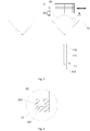
- the conveying mechanism comprises a hollow insulating shell 210 fixedly disposed on the lower part of the support 21, and a metal contact 211 movably disposed in the insulating shell 210.
- One end of the metal contact 211 is provided with a first contact point 2110, and the other end of the metal contact is electrically connected with a first conducting wire 212.
- a through hole for enabling the first contact point 2110 to protrude is provided on one end of the insulating shell 210, and a through hole for enabling the first conducting wire 212 to protrude is provided on the other end.
- An elastic member for driving the metal contact 211 to slide relative to the insulating shell 210 is disposed between the metal contact 211 and the insulating shell 210, particularly, the other end of the insulating shell 210 is fixedly connected with a fastening ring piece, a compression spring 214 for driving the metal contact 211 to operate is disposed between the other end of the metal contact 211 and the metal ring piece, the compression spring 214 is in a compressed state to provide an elastic force for protrusion of the first contact point 2110.
- a first connector 213 is fixedly connected to one end of the first conducting wire 212, threads are provided on the first connector 213, a matched threaded hole is provided on the other end of the metal contact 211, and the first connector 213 is connected with the metal contact 211 through threads.
- the other end of the first conducting wire 212 is electrically connected with the junction box of the photovoltaic module 20.
- a plurality of guide grooves 16 matching the metal contact 211 are provided on the transverse guide rail 12 and/or the longitudinal guide rail 13 at intervals.
- a second contact point 160 matching with the first contact point 2110 is provided on the bottom of the sliding slot 16.
- a second conducting wire 17 is fixedly connected with a second connector 170, threads are provided on the second connector 170, the second connector 170 is connected with the transverse guide rail 12 and/or the longitudinal guide rail 13 through the threads, an end of the second connector 170 extends to the bottom of the sliding slot 16, the second contact point 160 is electrically connected with the second connector 170, and the other end of the second conducting wire 17 is connected with an external power grid.
- Said one end of the metal contact 211 is slidably inserted into the sliding slot 16, and when the first contact point 2110 and the second contact 160 are in contact and conductive with each other, the photovoltaic module unit 2 is installed in place, that is, arriving at a specified module placement position.
- Guide bevels 161, 162 are provided in the sliding slot 16, and the guide bevels 161, 162 extend obliquely from the end of the sliding slot 16 toward the second contact point 160 in a manner of being gradually away from the support 21.
- Two guide bevels 161, 162 are provided and respectively located on two opposite sides of the second contact point 160.
- the metal contact 211 is inserted into the sliding slot 16, and under the action of the guide bevel 161 on one side, the compression spring 214 is gradually released to push the metal contact 211 to slide outward, and when metal contact moves to the second contact point 160, the first contact point 2110 and the second contact point 160 come into abutting contact with each other for conduction to achieve electrical connection, the photovoltaic module unit 2 is installed in place, and the electric energy generated by the photovoltaic module 20 is output by the first conducting wire 212 and the second conducting wire 17; and when the photovoltaic module unit 2 needs to be removed, the photovoltaic module unit 2 continues to move along the transverse guide rail 12 or the longitudinal guide rail 13, and under the action of the guide bevel 162 on the other side, the metal contact 211 gradually retracts back into the insulating shell 210, and the compression spring 214 is compressed.
- the module stacking warehouse 3 is disposed on the ground beside the photovoltaic ecological greenhouse for storing the photovoltaic module units 2, so that it is convenient to replenish the photovoltaic module units 2 in the photovoltaic ecological greenhouse or recycle the redundant photovoltaic module units 2. After being folded, the photovoltaic module units 2 are stacked in the module stacking warehouse 3, thus reducing the storage volume and saving the warehouse space.
- the maintenance warehouse 4 is disposed on the ground beside the module stacking warehouse 3 for recycling the faulty photovoltaic module units 2 for maintenance.
- the transmission device 5 is composed of a module conveying mechanism and a module lifting mechanism 54.
- the frame unit located at a vertex of the frame is used as a feeding/discharging point
- the conveying mechanism comprises a first conveying segment 51, a second conveying segment 52 and a third conveying segment 53
- the first conveying segment 51 extends from the module stacking warehouse 3 to a position under the feeding/discharging point
- the second conveying segment 52 is disposed on the conveying units 15 of the frame to communicate the conveying units 15 with the feeding/discharging point
- the third conveying segment 53 extends from the maintenance warehouse 4 to a position under the feeding/discharging point.
- the module lifting device is disposed below the feeding/discharging point for conveying the photovoltaic module on the first conveying segment 51 to the feeding/discharging point or conveying the photovoltaic module of the feeding/discharging point to the first conveying segment 51 or the second conveying segment 52.
- the first conveying segment 51, the second conveying segment 52 and the third conveying segment 53 of the conveying device utilize belt conveying mechanisms or chain conveying mechanisms or the like in the prior art, and the module lifting device utilizes a pneumatic or electric lifting platform or the like in the prior art, and thus will not be described in detail herein.
- a control device is formed by the module stacking warehouse 3, the maintenance warehouse 4, the transmission device 5, the hydraulic drive mechanism 113 of the column 11, the hydraulic drive mechanism 233 of the telescopic support 23, an environment detector 61, a soil humidity tester 63 and a controller 60, and is the control center for the operation of the entire photovoltaic ecological greenhouse.
- the controller 60 is the core part of the control device.
- the environment detector 61 is used for detecting the solar irradiation amount and the air moisture in the area on that day, and the soil humidity tester 63 is used for detecting the moisture content of the soil below the photovoltaic module on that day.
- the controller 60 is a PLC controller 60 or the like which is common in the prior art.
- the controller 60, the environment detector 61 and the soil humidity tester 63 are electrically connected by conducting wires, or connected in a wired transmission manner to obtain the solar irradiation amount and the air moisture content of the area on that day and the moisture content of the soil under the photovoltaic module on that day, the controller 60 is also connected with a third party data platform 63 to obtain a wide range of meteorological data of the area on that day to thereby perform comparison and verification on the solar irradiation amount of the area on that day and ensure the accuracy of the data detection of the solar irradiation amount.
- the controller 60 further determines whether the moisture content of the current soil meets the requirements of the plant at present according to the obtained moisture content of the soil and moisture content of the air, and supplements water to the soil timely if not.
- the controller 60 is further used for driving the transmission device 5 to operate, sending a control signal to the transmission device 5 in a conducting wire electric connection or wireless transmission mode, sending control signals of shutdown, forward conveying and reverse conveying to the first conveying segment 51, the second conveying segment 52 and the third conveying segment 53 of the transmission device 5 respectively, and sending a control signal of ascending or descending to the module lifting mechanism 54.
- the controller 60 also controls the extension and shrink of the column 11, and when the height of the crop exceeds 3m, sends a control signal of extension to the hydraulic drive mechanism 113 of the column 11, the column telescoping rod 112 extends to adaptively adjust the height of the frame of the greenhouse, and the maximum height does not exceed 10m.
- the controller 60 also controls the extension and shrink of the telescopic support 23, when photovoltaic module unit 2 is conveyed toward the frame, the controller 60 sends a control signal of extension to the hydraulic drive mechanism 233 of the telescopic support 23, the support telescoping rod 232 extends, and the photovoltaic module unit 2 is unfolded; and when the photovoltaic module unit 2 is conveyed to the module stacking warehouse 3 or the maintenance warehouse 4, the controller 60 sends a control signal of retracting to the hydraulic drive mechanism 233 of the telescopic support 23, the support telescoping rod 232 retracts back, and the photovoltaic module unit 2 is folded.
- each photovoltaic module unit 2 is detected and analyzed regularly, and in the case of an operation fault, the controller 60 sends a control signal of reverse conveying to the second conveying segment 52, sends a control signal of descending to the module lifting mechanism 54 and sends a control signal of reverse conveying to the third conveying segment 53, and the faulty photovoltaic module unit 2 is conveyed from the module placement position to the maintenance warehouse 4 for maintenance.
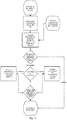
- a control method of the above photovoltaic ecological greenhouse comprises the following steps:
- step S4 if the configuration of the photovoltaic module units disposed on the previous day is in accord with the number of rows and the number of columns obtained in the step S3, the transmission device 5 is stopped; and if the configuration of the photovoltaic module units disposed on the previous day is not in accord with the number of rows and the number of columns obtained in the step S3, the control mechanism sends a control signal to drive the transmission device 5 to operate.
- the controller 60 drives the second conveying segment 52 and the first conveying segment 51 to perform reverse conveying and drives the module lifting mechanism 54 to descend to convey the redundant photovoltaic module units from the placement positions to the module stacking warehouse 3; and if the number of the photovoltaic module units disposed on the previous day is less than the number of rows and/or the number of columns obtained in the step S3, the controller 60 controls the first conveying segment 51 and the second conveying segment 52 to perform forward conveying to convey photovoltaic module units from the module stacking warehouse 3 to the designated placement positions to supplement the insufficient ones.
- the controller 60 further controls the extension and shrink of the telescopic support 23, and when the photovoltaic module unit 2 is conveyed toward the frame, the controller 60 sends a control signal of extension to the hydraulic drive mechanism 113 of the telescopic support 23, the support telescoping rod 232 extends, and the photovoltaic module unit 2 is unfolded; and when the photovoltaic module unit 2 is conveyed to the module stacking warehouse or the maintenance warehouse 4, the controller 60 sends a control signal of retracting to the hydraulic drive mechanism 113 of the telescopic support 23, the support telescoping rod 232 retracts back, and the photovoltaic module unit 2 is folded.
Landscapes
- Engineering & Computer Science (AREA)
- Life Sciences & Earth Sciences (AREA)
- Thermal Sciences (AREA)
- Physics & Mathematics (AREA)
- Sustainable Development (AREA)
- Sustainable Energy (AREA)
- Chemical & Material Sciences (AREA)
- Combustion & Propulsion (AREA)
- Mechanical Engineering (AREA)
- General Engineering & Computer Science (AREA)
- Environmental Sciences (AREA)
- Photovoltaic Devices (AREA)
- Greenhouses (AREA)
Claims (9)
- Photovoltaikmoduleinheit (2) für ein photovoltaisches ökologisches Gewächshaus, die Folgendes umfasst: einen Träger (21) zum Montieren und Verschieben auf einem Tragrahmen (1) eines photovoltaischen Kraftwerks oder eines photovoltaischen ökologischen Gewächshauses; und ein Photovoltaikmodul (20), das auf dem Träger (21) vorgesehen ist, wobei der Träger (21) einen Bodenträger (22) und einen vertikalen Teleskopträger (23), der an einer Seite des Bodenträgers (22) vorgesehen ist, umfasst und eine Seite des Photovoltaikmoduls (20) und ein oberes Ende des Teleskopträgers (23) verschiebbar und drehbar verbunden sind und die andere Seite des Photovoltaikmoduls (20) und die andere Seite des Bodenträgers (22) drehbar verbunden sind, dadurch gekennzeichnet, dass
die Photovoltaikmoduleinheit (2) ferner einen Transportmechanismus zum Transportieren der elektrischen Energie, die durch das Photovoltaikmodul (20) erzeugt worden ist, zu dem Tragrahmen (1) umfasst, wobei der Transportmechanismus mit einem ersten Kontaktpunkt (2210) zum Kontaktieren und elektrischen Verbinden des Tragrahmens (1) versehen ist, wobei der erste Kontaktpunkt (2110)- an dem unteren Teil des Trägers (21) vorgesehen ist,- mit dem Photovoltaikmodul (20) elektrisch verbunden ist und- ausgelegt ist, um an einen zweiten Kontaktpunkt (160) eines Verschiebeschlitzes (16) des Tragrahmens (1) angepasst zu sein. - Photovoltaikmoduleinheit (2) nach Anspruch 1, dadurch gekennzeichnet, dass der Teleskopträger (23) eine Trägerteleskophülse (231), die mit dem Bodenträger (22) fest verbunden ist, eine Trägerteleskopstange (232), die mit der Trägerteleskophülse (231) vertikal verschiebbar verbunden ist, und einen hydraulischen Antriebsmechanismus der teleskopischen (233), der zwischen der Trägerteleskophülse (231) und der Trägerteleskopstange (232) vorgesehen ist, umfasst, und die Trägerteleskopstange (232) mit dem Photovoltaikmodul (20) verbunden ist.
- Photovoltaikmoduleinheit (2) nach Anspruch 2, dadurch gekennzeichnet, dass die Trägerteleskopstange (232) mit dem Photovoltaikmodul (20) durch eine Trägerteleskopstange der zweiten Stufe verbunden ist, wobei die
Trägerteleskopstange (?) der zweiten Stufe mit der Trägerteleskopstange (232) vertikal verschiebbar verbunden ist und ein hydraulischer Antriebsmechanismus der zweiten Stufe zwischen der Trägerteleskopstange der zweiten Stufe und der Trägerteleskopstange (232) angeordnet ist. - Photovoltaikmoduleinheit (2) nach Anspruch 2, dadurch gekennzeichnet, dass der hydraulische Antriebsmechanismus ein Hydraulikölzylinder ist.
- Photovoltaikmoduleinheit (2) nach Anspruch 1, dadurch gekennzeichnet, dass der Transportmechanismus ferner eine hohle isolierende Hülle (210), die mit dem unteren Teil des Trägers (21) fest verbunden ist, und einen Metallkontakt (211), der in der isolierenden Hülle (210) beweglich vorgesehen ist, umfasst, wobei der erste Kontaktpunkt (2110) an einem Ende des Metallkontakts (211) gebildet ist, das andere Ende des Metallkontakts (211) mit dem Photovoltaikmodul (20) durch einen ersten leitenden Draht (212) verbunden ist, ein Durchgangsloch, um dem ersten Kontaktpunkt (2110) zu ermöglichen, herauszuragen, an einem Ende der isolierenden Hülle (210) gebildet ist, ein Durchgangsloch, um dem ersten leitenden Draht (212) zu ermöglichen, herauszuragen, an dem anderen Ende der isolierenden Hülle (210) gebildet ist und ein elastisches Element zum Bereitstellen einer elastischen Kraft, um dem Kontakt zu ermöglichen, herauszuragen, zwischen der isolierenden Hülle (210) und dem Metallkontakt (211) angeordnet ist.
- Photovoltaisches ökologisches Gewächshaus, das Folgendes umfasst: einen Tragrahmen (1), der auf dem Boden angeordnet ist, um einen Träger zu bilden, und mehrere Photovoltaikmoduleinheiten (2), die auf dem Tragrahmen (1) angeordnet sind, dadurch gekennzeichnet, dass die Photovoltaikmoduleinheit (2) die Photovoltaikmoduleinheit (2) nach einem der Ansprüche 1 - 5 ist.
- Photovoltaisches ökologisches Gewächshaus nach Anspruch 6, dadurch gekennzeichnet, dass der Tragrahmen (1) mit einem Rahmen zum Montieren der Photovoltaikmoduleinheit (2) versehen ist und der Bodenträger (22) der Photovoltaikmoduleinheit (2) verschiebbar und lösbar auf dem Rahmen angeordnet ist.
- Photovoltaisches ökologisches Gewächshaus nach Anspruch 7, dadurch gekennzeichnet, dass der Rahmen mit Führungsschienen (12, 13) versehen ist, eine Führungsnut (120, 130) auf den Führungsschienen (12, 13) vorgesehen ist, ein Schieber (220) auf dem unteren Teil des Bodenträgers (22) angeordnet ist und der Schieber (220) in die Führungsnut (120, 130) verschiebbar eingesetzt wird.
- Photovoltaisches ökologisches Gewächshaus nach Anspruch 8, wobei der Transportmechanismus einen zweiten Kontaktpunkt (160) umfasst, der auf der Führungsschiene (12, 13) vorgesehen ist, wobei der zweite Kontaktpunkt (160) mit einem zweiten leitenden Draht (17) elektrisch verbunden ist, ein Verschiebeschlitz (16) auf der Führungsschiene (12, 13) vorgesehen ist, der zweite Kontaktpunkt (160) auf dem Boden des Verschiebeschlitzes (16) vorgesehen ist und der Transportmechanismus ferner eine hohle isolierende Hülle (210), die an dem unteren Teil des Trägers (21) fest angeordnet ist, und einen Metallkontakt (211), der in der isolierenden Hülle (210) beweglich angeordnet ist, umfasst, wobei der erste Kontaktpunkt (2110) an einem Ende des Metallkontakts (211) gebildet ist, das andere Ende des Metallkontakts (211) mit dem ersten leitenden Draht (212) elektrisch verbunden ist, ein Durchgangsloch, um dem ersten Kontaktpunkt (2110) zu ermöglichen, herauszuragen, an einem Ende der isolierenden Hülle (210) gebildet ist, ein Durchgangsloch, um dem ersten leitenden Draht (212) zu ermöglichen, herauszuragen, an dem anderen Ende der isolierenden Hülle (210) gebildet ist, ein elastisches Element, um den Metallkontakt (211) anzutreiben, sich zu bewegen, zwischen dem Metallkontakt (211) und der isolierenden Hülle (210) angeordnet ist und dann, wenn die Photovoltaikmoduleinheit (2) an der Stelle installiert wird, der Metallkontakt (211) in den Verschiebeschlitz (16) eingesetzt wird und der erste Kontaktpunkt (2110) in Kontakt und in elektrische Verbindung mit dem zweiten Kontaktpunkt (160) gelangt.
Applications Claiming Priority (2)
| Application Number | Priority Date | Filing Date | Title |
|---|---|---|---|
| CN201610146103.8A CN105766472B (zh) | 2016-03-15 | 2016-03-15 | 光伏生态大棚及其光伏组件单元 |
| PCT/CN2016/081539 WO2017156847A1 (zh) | 2016-03-15 | 2016-05-10 | 光伏生态大棚及其光伏组件单元 |
Publications (3)
| Publication Number | Publication Date |
|---|---|
| EP3432469A1 EP3432469A1 (de) | 2019-01-23 |
| EP3432469A4 EP3432469A4 (de) | 2019-04-03 |
| EP3432469B1 true EP3432469B1 (de) | 2021-01-20 |
Family
ID=56392701
Family Applications (1)
| Application Number | Title | Priority Date | Filing Date |
|---|---|---|---|
| EP16894010.4A Active EP3432469B1 (de) | 2016-03-15 | 2016-05-10 | Fotovoltaisches ökologisches gewächshaus und fotovoltaikmoduleinheit davon |
Country Status (3)
| Country | Link |
|---|---|
| EP (1) | EP3432469B1 (de) |
| CN (1) | CN105766472B (de) |
| WO (1) | WO2017156847A1 (de) |
Families Citing this family (9)
| Publication number | Priority date | Publication date | Assignee | Title |
|---|---|---|---|---|
| CN106949357A (zh) * | 2017-05-05 | 2017-07-14 | 四川省绵阳太古软件有限公司 | 一种框型四脚气象支架 |
| CN107853024B (zh) * | 2017-10-31 | 2020-08-25 | 台州中知英健机械自动化有限公司 | 一种栽植棚 |
| CN107593181B (zh) * | 2017-10-31 | 2020-11-10 | 台州中知英健机械自动化有限公司 | 一种栽植棚 |
| CN107896725B (zh) * | 2017-10-31 | 2020-08-25 | 台州中知英健机械自动化有限公司 | 一种栽植棚 |
| CN110176741B (zh) * | 2019-05-27 | 2020-09-22 | 季华实验室 | 线缆布线平台 |
| CN114553121B (zh) * | 2022-03-15 | 2025-04-04 | 泰州学院 | 一种用于温室大棚的太阳能光伏发电装置 |
| CN115441821A (zh) * | 2022-09-30 | 2022-12-06 | 江苏龙恒新能源有限公司 | 一种p型背结接触太阳能电池的支撑结构 |
| DE202022002406U1 (de) | 2022-11-05 | 2022-11-15 | Ifl Ingenieurbüro Für Leichtbau Gmbh & Co Kg | Gewächshaus mit wenigstens einer Wand und/oder einem Dach |
| CN116195453B (zh) * | 2022-12-21 | 2024-06-28 | 中建材浚鑫科技有限公司 | 一种基于彩色双玻组件的温室阴阳棚屋顶结构 |
Family Cites Families (23)
| Publication number | Priority date | Publication date | Assignee | Title |
|---|---|---|---|---|
| US20070056617A1 (en) * | 2005-09-12 | 2007-03-15 | Li Wanda Y | Solar energy collection system for outdoor umbrella |
| US7476832B2 (en) * | 2006-06-29 | 2009-01-13 | Herb Vendig | Seasonally adjustable mounting system for solar panels having dual motor assembly |
| DE102009002504A1 (de) * | 2009-04-20 | 2010-10-28 | Centrotec Composites Gmbh | Träger eines Solarkollektormoduls |
| US8720125B2 (en) * | 2009-07-28 | 2014-05-13 | Micah F. Andretich | Sustainable, mobile, expandable structure |
| TW201037849A (en) * | 2010-04-16 | 2010-10-16 | Fung Gin Da Energy Science & Technology Co Ltd | Electrical energy generation device capable of chasing the sun for focusing light |
| KR101291390B1 (ko) * | 2010-07-14 | 2013-07-30 | 이은석 | 태양광 발전설비를 구비한 에너지 절감형 온실 |
| US9113603B2 (en) * | 2011-01-18 | 2015-08-25 | Lite-On Green Technologies, Inc. | Solar greenhouse structure |
| CN202721147U (zh) * | 2012-08-27 | 2013-02-06 | 陕西光伏产业有限公司 | 带有液压式调节装置的光伏支架 |
| CN202721148U (zh) * | 2012-08-27 | 2013-02-06 | 陕西光伏产业有限公司 | 可调节角度的光伏支架 |
| CN202839661U (zh) * | 2012-09-29 | 2013-03-27 | 英利能源(中国)有限公司 | 一种光伏组件及其可调支架 |
| US20140284292A1 (en) * | 2013-03-19 | 2014-09-25 | Richard Pantel | Photovoltaic panel support with wheels |
| MA35588B1 (fr) * | 2013-04-12 | 2014-11-01 | Hamza Dadoune | Mecanisme d'optimisation de surface |
| CN203482152U (zh) * | 2013-09-22 | 2014-03-12 | 万丰奥特控股集团有限公司 | 一种折叠式太阳能电池板支架 |
| AU2014218426A1 (en) * | 2013-12-20 | 2015-07-09 | Laing O'rourke Australia Pty Ltd | A solar array assembly |
| CN203851086U (zh) * | 2014-02-18 | 2014-09-24 | 浙江昱辉阳光能源有限公司 | 一种可调节支架 |
| CN203968803U (zh) * | 2014-06-06 | 2014-12-03 | 特变电工新疆新能源股份有限公司 | 一种光伏农业大棚 |
| CN104184393B (zh) * | 2014-08-19 | 2016-08-24 | 江苏朗禾农光聚合科技有限公司中国 | 农业大棚式的密集型光伏发电装置 |
| CN204579326U (zh) * | 2015-04-29 | 2015-08-26 | 北京汉能光伏投资有限公司 | 温棚的遮阳装置及温棚 |
| CN204615731U (zh) * | 2015-05-05 | 2015-09-02 | 汪清明 | 一种气压控制升降的太阳能光伏板装置 |
| CN204860326U (zh) * | 2015-07-05 | 2015-12-16 | 新疆石河子职业技术学院 | 一种新型光伏农业大棚 |
| CN204929840U (zh) * | 2015-07-10 | 2016-01-06 | 常州常源电力设备有限公司 | 跟踪式太阳能大棚电站 |
| CN105594512B (zh) * | 2016-03-15 | 2018-10-12 | 苏州腾晖光伏技术有限公司 | 光伏生态大棚及其支承架 |
| CN205389723U (zh) * | 2016-03-15 | 2016-07-27 | 中利腾晖光伏科技有限公司 | 光伏生态大棚及其光伏组件单元 |
-
2016
- 2016-03-15 CN CN201610146103.8A patent/CN105766472B/zh active Active
- 2016-05-10 WO PCT/CN2016/081539 patent/WO2017156847A1/zh not_active Ceased
- 2016-05-10 EP EP16894010.4A patent/EP3432469B1/de active Active
Non-Patent Citations (1)
| Title |
|---|
| None * |
Also Published As
| Publication number | Publication date |
|---|---|
| CN105766472B (zh) | 2018-09-25 |
| WO2017156847A1 (zh) | 2017-09-21 |
| CN105766472A (zh) | 2016-07-20 |
| EP3432469A4 (de) | 2019-04-03 |
| EP3432469A1 (de) | 2019-01-23 |
Similar Documents
| Publication | Publication Date | Title |
|---|---|---|
| EP3432469A1 (de) | Fotovoltaisches ökologisches gewächshaus und fotovoltaikmoduleinheit davon | |
| KR101102381B1 (ko) | 이동형 태양광 발전장치 | |
| KR20190008846A (ko) | 로봇 어셈블리를 갖는 진보된 솔라 pv 시스템 | |
| CN109208833B (zh) | 一种房顶太阳能板安装结构 | |
| CN105594512B (zh) | 光伏生态大棚及其支承架 | |
| CN105613136B (zh) | 光伏生态大棚的控制方法及控制装置 | |
| CN105613125B (zh) | 一种光伏生态大棚及其支承架 | |
| CN111064427A (zh) | 太阳能光伏组件及光伏发电装置 | |
| CN205378614U (zh) | 一种光伏生态大棚及其支承架 | |
| EP3560858B1 (de) | Fotovoltaischer behälter | |
| CN205389724U (zh) | 光伏生态大棚及其支承架 | |
| CN205389723U (zh) | 光伏生态大棚及其光伏组件单元 | |
| CN111669115B (zh) | 快速收纳的太阳能光伏板装置 | |
| CN205389743U (zh) | 光伏生态大棚的控制装置 | |
| CN219576927U (zh) | 一种可扩展太阳能组件 | |
| CN203482152U (zh) | 一种折叠式太阳能电池板支架 | |
| CN208749211U (zh) | 环保节能型便携式基站 | |
| KR20150059584A (ko) | 풍력발전기 설치장치 및 이를 이용한 풍력발전기 설치방법 | |
| CN112495824B (zh) | 一种太阳能电板的传输机构 | |
| CN115781228A (zh) | 一种水冷电箱安装工装 | |
| CN209989038U (zh) | 一种模块式绝缘高空作业车 | |
| CN218976031U (zh) | 户外安全型小型电力柜 | |
| CN222041711U (zh) | 一种无边框光伏组件生产用输送装置 | |
| CN221103275U (zh) | 光伏支架以及光伏系统 | |
| CN219234659U (zh) | 一种具备较高安全系数的移动复合机器人 |
Legal Events
| Date | Code | Title | Description |
|---|---|---|---|
| STAA | Information on the status of an ep patent application or granted ep patent |
Free format text: STATUS: THE INTERNATIONAL PUBLICATION HAS BEEN MADE |
|
| PUAI | Public reference made under article 153(3) epc to a published international application that has entered the european phase |
Free format text: ORIGINAL CODE: 0009012 |
|
| STAA | Information on the status of an ep patent application or granted ep patent |
Free format text: STATUS: REQUEST FOR EXAMINATION WAS MADE |
|
| 17P | Request for examination filed |
Effective date: 20181005 |
|
| AK | Designated contracting states |
Kind code of ref document: A1 Designated state(s): AL AT BE BG CH CY CZ DE DK EE ES FI FR GB GR HR HU IE IS IT LI LT LU LV MC MK MT NL NO PL PT RO RS SE SI SK SM TR |
|
| AX | Request for extension of the european patent |
Extension state: BA ME |
|
| A4 | Supplementary search report drawn up and despatched |
Effective date: 20190306 |
|
| RIC1 | Information provided on ipc code assigned before grant |
Ipc: F24S 30/00 20180101ALN20190227BHEP Ipc: H02S 10/40 20140101ALI20190227BHEP Ipc: H02S 20/20 20140101AFI20190227BHEP Ipc: H02S 20/30 20140101ALI20190227BHEP |
|
| DAV | Request for validation of the european patent (deleted) | ||
| DAX | Request for extension of the european patent (deleted) | ||
| RIC1 | Information provided on ipc code assigned before grant |
Ipc: H02S 20/30 20140101ALI20200714BHEP Ipc: H02S 10/40 20140101ALI20200714BHEP Ipc: H02S 20/20 20140101AFI20200714BHEP Ipc: F24S 30/00 20180101ALN20200714BHEP |
|
| RIC1 | Information provided on ipc code assigned before grant |
Ipc: F24S 30/00 20180101ALN20200722BHEP Ipc: H02S 20/30 20140101ALI20200722BHEP Ipc: H02S 10/40 20140101ALI20200722BHEP Ipc: H02S 20/20 20140101AFI20200722BHEP |
|
| GRAP | Despatch of communication of intention to grant a patent |
Free format text: ORIGINAL CODE: EPIDOSNIGR1 |
|
| STAA | Information on the status of an ep patent application or granted ep patent |
Free format text: STATUS: GRANT OF PATENT IS INTENDED |
|
| INTG | Intention to grant announced |
Effective date: 20200904 |
|
| GRAS | Grant fee paid |
Free format text: ORIGINAL CODE: EPIDOSNIGR3 |
|
| GRAA | (expected) grant |
Free format text: ORIGINAL CODE: 0009210 |
|
| STAA | Information on the status of an ep patent application or granted ep patent |
Free format text: STATUS: THE PATENT HAS BEEN GRANTED |
|
| AK | Designated contracting states |
Kind code of ref document: B1 Designated state(s): AL AT BE BG CH CY CZ DE DK EE ES FI FR GB GR HR HU IE IS IT LI LT LU LV MC MK MT NL NO PL PT RO RS SE SI SK SM TR |
|
| REG | Reference to a national code |
Ref country code: GB Ref legal event code: FG4D |
|
| REG | Reference to a national code |
Ref country code: CH Ref legal event code: EP |
|
| REG | Reference to a national code |
Ref country code: DE Ref legal event code: R096 Ref document number: 602016051899 Country of ref document: DE |
|
| REG | Reference to a national code |
Ref country code: AT Ref legal event code: REF Ref document number: 1357227 Country of ref document: AT Kind code of ref document: T Effective date: 20210215 |
|
| REG | Reference to a national code |
Ref country code: IE Ref legal event code: FG4D |
|
| REG | Reference to a national code |
Ref country code: NL Ref legal event code: FP |
|
| REG | Reference to a national code |
Ref country code: LT Ref legal event code: MG9D |
|
| REG | Reference to a national code |
Ref country code: AT Ref legal event code: MK05 Ref document number: 1357227 Country of ref document: AT Kind code of ref document: T Effective date: 20210120 |
|
| PG25 | Lapsed in a contracting state [announced via postgrant information from national office to epo] |
Ref country code: GR Free format text: LAPSE BECAUSE OF FAILURE TO SUBMIT A TRANSLATION OF THE DESCRIPTION OR TO PAY THE FEE WITHIN THE PRESCRIBED TIME-LIMIT Effective date: 20210421 Ref country code: HR Free format text: LAPSE BECAUSE OF FAILURE TO SUBMIT A TRANSLATION OF THE DESCRIPTION OR TO PAY THE FEE WITHIN THE PRESCRIBED TIME-LIMIT Effective date: 20210120 Ref country code: FI Free format text: LAPSE BECAUSE OF FAILURE TO SUBMIT A TRANSLATION OF THE DESCRIPTION OR TO PAY THE FEE WITHIN THE PRESCRIBED TIME-LIMIT Effective date: 20210120 Ref country code: NO Free format text: LAPSE BECAUSE OF FAILURE TO SUBMIT A TRANSLATION OF THE DESCRIPTION OR TO PAY THE FEE WITHIN THE PRESCRIBED TIME-LIMIT Effective date: 20210420 Ref country code: PT Free format text: LAPSE BECAUSE OF FAILURE TO SUBMIT A TRANSLATION OF THE DESCRIPTION OR TO PAY THE FEE WITHIN THE PRESCRIBED TIME-LIMIT Effective date: 20210520 Ref country code: LT Free format text: LAPSE BECAUSE OF FAILURE TO SUBMIT A TRANSLATION OF THE DESCRIPTION OR TO PAY THE FEE WITHIN THE PRESCRIBED TIME-LIMIT Effective date: 20210120 Ref country code: BG Free format text: LAPSE BECAUSE OF FAILURE TO SUBMIT A TRANSLATION OF THE DESCRIPTION OR TO PAY THE FEE WITHIN THE PRESCRIBED TIME-LIMIT Effective date: 20210420 |
|
| PG25 | Lapsed in a contracting state [announced via postgrant information from national office to epo] |
Ref country code: SE Free format text: LAPSE BECAUSE OF FAILURE TO SUBMIT A TRANSLATION OF THE DESCRIPTION OR TO PAY THE FEE WITHIN THE PRESCRIBED TIME-LIMIT Effective date: 20210120 Ref country code: AT Free format text: LAPSE BECAUSE OF FAILURE TO SUBMIT A TRANSLATION OF THE DESCRIPTION OR TO PAY THE FEE WITHIN THE PRESCRIBED TIME-LIMIT Effective date: 20210120 Ref country code: RS Free format text: LAPSE BECAUSE OF FAILURE TO SUBMIT A TRANSLATION OF THE DESCRIPTION OR TO PAY THE FEE WITHIN THE PRESCRIBED TIME-LIMIT Effective date: 20210120 Ref country code: PL Free format text: LAPSE BECAUSE OF FAILURE TO SUBMIT A TRANSLATION OF THE DESCRIPTION OR TO PAY THE FEE WITHIN THE PRESCRIBED TIME-LIMIT Effective date: 20210120 Ref country code: LV Free format text: LAPSE BECAUSE OF FAILURE TO SUBMIT A TRANSLATION OF THE DESCRIPTION OR TO PAY THE FEE WITHIN THE PRESCRIBED TIME-LIMIT Effective date: 20210120 |
|
| PG25 | Lapsed in a contracting state [announced via postgrant information from national office to epo] |
Ref country code: IS Free format text: LAPSE BECAUSE OF FAILURE TO SUBMIT A TRANSLATION OF THE DESCRIPTION OR TO PAY THE FEE WITHIN THE PRESCRIBED TIME-LIMIT Effective date: 20210520 |
|
| REG | Reference to a national code |
Ref country code: DE Ref legal event code: R097 Ref document number: 602016051899 Country of ref document: DE |
|
| PG25 | Lapsed in a contracting state [announced via postgrant information from national office to epo] |
Ref country code: SM Free format text: LAPSE BECAUSE OF FAILURE TO SUBMIT A TRANSLATION OF THE DESCRIPTION OR TO PAY THE FEE WITHIN THE PRESCRIBED TIME-LIMIT Effective date: 20210120 Ref country code: CZ Free format text: LAPSE BECAUSE OF FAILURE TO SUBMIT A TRANSLATION OF THE DESCRIPTION OR TO PAY THE FEE WITHIN THE PRESCRIBED TIME-LIMIT Effective date: 20210120 Ref country code: EE Free format text: LAPSE BECAUSE OF FAILURE TO SUBMIT A TRANSLATION OF THE DESCRIPTION OR TO PAY THE FEE WITHIN THE PRESCRIBED TIME-LIMIT Effective date: 20210120 |
|
| PLBE | No opposition filed within time limit |
Free format text: ORIGINAL CODE: 0009261 |
|
| STAA | Information on the status of an ep patent application or granted ep patent |
Free format text: STATUS: NO OPPOSITION FILED WITHIN TIME LIMIT |
|
| PG25 | Lapsed in a contracting state [announced via postgrant information from national office to epo] |
Ref country code: RO Free format text: LAPSE BECAUSE OF FAILURE TO SUBMIT A TRANSLATION OF THE DESCRIPTION OR TO PAY THE FEE WITHIN THE PRESCRIBED TIME-LIMIT Effective date: 20210120 Ref country code: SK Free format text: LAPSE BECAUSE OF FAILURE TO SUBMIT A TRANSLATION OF THE DESCRIPTION OR TO PAY THE FEE WITHIN THE PRESCRIBED TIME-LIMIT Effective date: 20210120 Ref country code: DK Free format text: LAPSE BECAUSE OF FAILURE TO SUBMIT A TRANSLATION OF THE DESCRIPTION OR TO PAY THE FEE WITHIN THE PRESCRIBED TIME-LIMIT Effective date: 20210120 |
|
| 26N | No opposition filed |
Effective date: 20211021 |
|
| REG | Reference to a national code |
Ref country code: CH Ref legal event code: PL |
|
| GBPC | Gb: european patent ceased through non-payment of renewal fee |
Effective date: 20210510 |
|
| PG25 | Lapsed in a contracting state [announced via postgrant information from national office to epo] |
Ref country code: ES Free format text: LAPSE BECAUSE OF FAILURE TO SUBMIT A TRANSLATION OF THE DESCRIPTION OR TO PAY THE FEE WITHIN THE PRESCRIBED TIME-LIMIT Effective date: 20210120 Ref country code: MC Free format text: LAPSE BECAUSE OF FAILURE TO SUBMIT A TRANSLATION OF THE DESCRIPTION OR TO PAY THE FEE WITHIN THE PRESCRIBED TIME-LIMIT Effective date: 20210120 Ref country code: LI Free format text: LAPSE BECAUSE OF NON-PAYMENT OF DUE FEES Effective date: 20210531 Ref country code: LU Free format text: LAPSE BECAUSE OF NON-PAYMENT OF DUE FEES Effective date: 20210510 Ref country code: CH Free format text: LAPSE BECAUSE OF NON-PAYMENT OF DUE FEES Effective date: 20210531 Ref country code: AL Free format text: LAPSE BECAUSE OF FAILURE TO SUBMIT A TRANSLATION OF THE DESCRIPTION OR TO PAY THE FEE WITHIN THE PRESCRIBED TIME-LIMIT Effective date: 20210120 |
|
| REG | Reference to a national code |
Ref country code: BE Ref legal event code: MM Effective date: 20210531 |
|
| PG25 | Lapsed in a contracting state [announced via postgrant information from national office to epo] |
Ref country code: SI Free format text: LAPSE BECAUSE OF FAILURE TO SUBMIT A TRANSLATION OF THE DESCRIPTION OR TO PAY THE FEE WITHIN THE PRESCRIBED TIME-LIMIT Effective date: 20210120 |
|
| PG25 | Lapsed in a contracting state [announced via postgrant information from national office to epo] |
Ref country code: IT Free format text: LAPSE BECAUSE OF FAILURE TO SUBMIT A TRANSLATION OF THE DESCRIPTION OR TO PAY THE FEE WITHIN THE PRESCRIBED TIME-LIMIT Effective date: 20210120 Ref country code: IE Free format text: LAPSE BECAUSE OF NON-PAYMENT OF DUE FEES Effective date: 20210510 Ref country code: GB Free format text: LAPSE BECAUSE OF NON-PAYMENT OF DUE FEES Effective date: 20210510 |
|
| PG25 | Lapsed in a contracting state [announced via postgrant information from national office to epo] |
Ref country code: IS Free format text: LAPSE BECAUSE OF FAILURE TO SUBMIT A TRANSLATION OF THE DESCRIPTION OR TO PAY THE FEE WITHIN THE PRESCRIBED TIME-LIMIT Effective date: 20210520 |
|
| PG25 | Lapsed in a contracting state [announced via postgrant information from national office to epo] |
Ref country code: BE Free format text: LAPSE BECAUSE OF NON-PAYMENT OF DUE FEES Effective date: 20210531 |
|
| PG25 | Lapsed in a contracting state [announced via postgrant information from national office to epo] |
Ref country code: CY Free format text: LAPSE BECAUSE OF FAILURE TO SUBMIT A TRANSLATION OF THE DESCRIPTION OR TO PAY THE FEE WITHIN THE PRESCRIBED TIME-LIMIT Effective date: 20210120 |
|
| PG25 | Lapsed in a contracting state [announced via postgrant information from national office to epo] |
Ref country code: HU Free format text: LAPSE BECAUSE OF FAILURE TO SUBMIT A TRANSLATION OF THE DESCRIPTION OR TO PAY THE FEE WITHIN THE PRESCRIBED TIME-LIMIT; INVALID AB INITIO Effective date: 20160510 |
|
| PG25 | Lapsed in a contracting state [announced via postgrant information from national office to epo] |
Ref country code: MK Free format text: LAPSE BECAUSE OF FAILURE TO SUBMIT A TRANSLATION OF THE DESCRIPTION OR TO PAY THE FEE WITHIN THE PRESCRIBED TIME-LIMIT Effective date: 20210120 |
|
| PG25 | Lapsed in a contracting state [announced via postgrant information from national office to epo] |
Ref country code: TR Free format text: LAPSE BECAUSE OF FAILURE TO SUBMIT A TRANSLATION OF THE DESCRIPTION OR TO PAY THE FEE WITHIN THE PRESCRIBED TIME-LIMIT Effective date: 20210120 |
|
| PG25 | Lapsed in a contracting state [announced via postgrant information from national office to epo] |
Ref country code: MT Free format text: LAPSE BECAUSE OF FAILURE TO SUBMIT A TRANSLATION OF THE DESCRIPTION OR TO PAY THE FEE WITHIN THE PRESCRIBED TIME-LIMIT Effective date: 20210120 |
|
| PGFP | Annual fee paid to national office [announced via postgrant information from national office to epo] |
Ref country code: NL Payment date: 20250523 Year of fee payment: 10 |
|
| PGFP | Annual fee paid to national office [announced via postgrant information from national office to epo] |
Ref country code: DE Payment date: 20250602 Year of fee payment: 10 |
|
| PGFP | Annual fee paid to national office [announced via postgrant information from national office to epo] |
Ref country code: FR Payment date: 20250520 Year of fee payment: 10 |