EP3432452A1 - Moteur couple comprenant un support de bobines statoriques et un corps magnétique y compris un aimant permanent - Google Patents
Moteur couple comprenant un support de bobines statoriques et un corps magnétique y compris un aimant permanent Download PDFInfo
- Publication number
- EP3432452A1 EP3432452A1 EP18181458.3A EP18181458A EP3432452A1 EP 3432452 A1 EP3432452 A1 EP 3432452A1 EP 18181458 A EP18181458 A EP 18181458A EP 3432452 A1 EP3432452 A1 EP 3432452A1
- Authority
- EP
- European Patent Office
- Prior art keywords
- stator
- torque motor
- support
- receiving
- rotor
- Prior art date
- Legal status (The legal status is an assumption and is not a legal conclusion. Google has not performed a legal analysis and makes no representation as to the accuracy of the status listed.)
- Granted
Links
Images

Classifications
-
- H—ELECTRICITY
- H02—GENERATION; CONVERSION OR DISTRIBUTION OF ELECTRIC POWER
- H02K—DYNAMO-ELECTRIC MACHINES
- H02K26/00—Machines adapted to function as torque motors, i.e. to exert a torque when stalled
-
- H—ELECTRICITY
- H02—GENERATION; CONVERSION OR DISTRIBUTION OF ELECTRIC POWER
- H02K—DYNAMO-ELECTRIC MACHINES
- H02K1/00—Details of the magnetic circuit
- H02K1/06—Details of the magnetic circuit characterised by the shape, form or construction
- H02K1/12—Stationary parts of the magnetic circuit
- H02K1/17—Stator cores with permanent magnets
-
- H—ELECTRICITY
- H02—GENERATION; CONVERSION OR DISTRIBUTION OF ELECTRIC POWER
- H02K—DYNAMO-ELECTRIC MACHINES
- H02K1/00—Details of the magnetic circuit
- H02K1/06—Details of the magnetic circuit characterised by the shape, form or construction
- H02K1/12—Stationary parts of the magnetic circuit
- H02K1/14—Stator cores with salient poles
- H02K1/146—Stator cores with salient poles consisting of a generally annular yoke with salient poles
-
- H—ELECTRICITY
- H02—GENERATION; CONVERSION OR DISTRIBUTION OF ELECTRIC POWER
- H02K—DYNAMO-ELECTRIC MACHINES
- H02K1/00—Details of the magnetic circuit
- H02K1/06—Details of the magnetic circuit characterised by the shape, form or construction
- H02K1/12—Stationary parts of the magnetic circuit
- H02K1/16—Stator cores with slots for windings
-
- H—ELECTRICITY
- H02—GENERATION; CONVERSION OR DISTRIBUTION OF ELECTRIC POWER
- H02K—DYNAMO-ELECTRIC MACHINES
- H02K15/00—Processes or apparatus specially adapted for manufacturing, assembling, maintaining or repairing of dynamo-electric machines
- H02K15/02—Processes or apparatus specially adapted for manufacturing, assembling, maintaining or repairing of dynamo-electric machines of stator or rotor bodies
- H02K15/03—Processes or apparatus specially adapted for manufacturing, assembling, maintaining or repairing of dynamo-electric machines of stator or rotor bodies having permanent magnets
-
- H—ELECTRICITY
- H02—GENERATION; CONVERSION OR DISTRIBUTION OF ELECTRIC POWER
- H02K—DYNAMO-ELECTRIC MACHINES
- H02K3/00—Details of windings
- H02K3/30—Windings characterised by the insulating material
-
- H—ELECTRICITY
- H02—GENERATION; CONVERSION OR DISTRIBUTION OF ELECTRIC POWER
- H02K—DYNAMO-ELECTRIC MACHINES
- H02K3/00—Details of windings
- H02K3/46—Fastening of windings on the stator or rotor structure
- H02K3/48—Fastening of windings on the stator or rotor structure in slots
-
- H—ELECTRICITY
- H02—GENERATION; CONVERSION OR DISTRIBUTION OF ELECTRIC POWER
- H02K—DYNAMO-ELECTRIC MACHINES
- H02K5/00—Casings; Enclosures; Supports
- H02K5/04—Casings or enclosures characterised by the shape, form or construction thereof
- H02K5/16—Means for supporting bearings, e.g. insulating supports or means for fitting bearings in the bearing-shields
-
- H—ELECTRICITY
- H02—GENERATION; CONVERSION OR DISTRIBUTION OF ELECTRIC POWER
- H02K—DYNAMO-ELECTRIC MACHINES
- H02K15/00—Processes or apparatus specially adapted for manufacturing, assembling, maintaining or repairing of dynamo-electric machines
- H02K15/04—Processes or apparatus specially adapted for manufacturing, assembling, maintaining or repairing of dynamo-electric machines of windings prior to their mounting into the machines
- H02K15/043—Processes or apparatus specially adapted for manufacturing, assembling, maintaining or repairing of dynamo-electric machines of windings prior to their mounting into the machines winding flat conductive wires or sheets
- H02K15/0431—Concentrated windings
-
- H—ELECTRICITY
- H02—GENERATION; CONVERSION OR DISTRIBUTION OF ELECTRIC POWER
- H02K—DYNAMO-ELECTRIC MACHINES
- H02K2203/00—Specific aspects not provided for in the other groups of this subclass relating to the windings
- H02K2203/12—Machines characterised by the bobbins for supporting the windings
-
- H—ELECTRICITY
- H02—GENERATION; CONVERSION OR DISTRIBUTION OF ELECTRIC POWER
- H02K—DYNAMO-ELECTRIC MACHINES
- H02K3/00—Details of windings
- H02K3/46—Fastening of windings on the stator or rotor structure
- H02K3/52—Fastening salient pole windings or connections thereto
- H02K3/521—Fastening salient pole windings or connections thereto applicable to stators only
- H02K3/522—Fastening salient pole windings or connections thereto applicable to stators only for generally annular cores with salient poles
Definitions
- the invention relates to a torque motor, in particular a limited travel torque motor for aeronautical applications.
- Torque motors are electric motors that aim to obtain a torque by the circulation of an electric current of predetermined intensity in coils placed in a permanent magnetic field.
- a torque motor comprises an armature, which is the part of the motor that carries the coils traversed by the current and an inductor, which is the complementary part of the motor that generates the permanent magnetic field.
- This permanent magnetic field is generally generated by permanent magnets formed on the rotor or stator of the motor.
- Torque motors are frequently used in the field of aeronautics, for example to equip pneumatic actuators with air bleed valves, cabin pressure regulating valves, fuel flow control systems, etc.
- the preferred architecture often comprises a one-piece stator carrying at least one permanent magnet, stator coils and a rotor forming the armature.
- This architecture provides engines that are compact and minimize rotor inertia.
- This architecture imposes certain constraints during the manufacture of the engine among which the need to integrate the permanent magnets very in upstream of the manufacturing process, and in particular upstream of the winding operations; the realization of stator electrical windings on specific tools; the insulation of the windings prior to their integration into the engine; and the integration of the stator windings thus produced inside the stator monobloc magnetic circuit by delicate operations which consist of bringing the coils back radially onto the magnetic circuit (from the inside or the outside of the magnetic circuit, and which consists of some applications to manually shape the stator coils and to compact them to be able to fit them in the one-piece stator).
- This manufacturing process is long, tedious and expensive. In addition, it presents risks of poor electrical insulation resulting from the manipulation of the stator coils during their integration in the stator magnetic circuit. Also, it is common during the assembly operations of these torque motors to have to discard a significant number of parts produced due to an alteration of the stator coils during their integration in the stator circuit. In addition, this manufacturing process prevents the use of ceramic coated yarns.
- the inventors have therefore sought to improve torque motors, in particular torque motors intended for aeronautical applications.
- the inventors have in particular sought to propose a new torque motor structure that facilitates the assembly operations of this torque motor.
- the invention aims to provide a torque motor that overcomes at least some of the disadvantages of known torque motors.
- the invention aims in particular to provide, in at least one embodiment, a torque motor which has a structure to facilitate assembly and manufacturing operations.
- the invention aims in particular to provide, in at least one embodiment, a torque motor which has a structure for limiting the scrapping of torque motors during assembly operations.
- the invention also aims to provide, in at least one embodiment, a torque motor that has improved electrical insulation performance over previous solutions.
- the invention also aims to provide, in at least one embodiment, a torque motor whose structure can significantly reduce the time and cost of manufacture and assembly.
- the invention also aims to provide a torque motor whose structure allows a particular adaptation to the automation of manufacture, that is to say with manual operations reduced or even zero.
- the invention also aims to provide, in at least one embodiment, a torque motor whose structure allows adaptation to use in frameless mode, better known by the English name of " frameless ".
- the invention also aims at providing a torque motor whose structure makes it possible, at a lower cost, to reduce the radial distance between the stator teeth and the rotor teeth forming the air gap of the motor.
- the invention relates to a torque motor comprising a stator and a rotor extending along the same central axis, said stator further comprising a one-piece magnetic body, at least one pair of radial teeth extending along the central axis and defining notches for receiving stator coils and forming a radial air gap with said rotor, and at least one permanent magnet carried by said magnetic body.
- a torque motor is characterized in that it comprises a winding support for the stator coils comprising a hollow body extending along the central axis and delimiting a receiving chamber of said rotor, said support further comprising receiving housings of said stator coils extending in planes parallel to the central axis, and having peripheral radial walls conformed to said notches of said one-piece magnetic body, so that the integration of the stator coils into said stator consists of axially inserting in said one-piece magnetic body, said winding support equipped with said stator coils.
- a torque motor according to the invention therefore comprises a winding support stator coils.
- This winding support is shaped to the one-piece stator magnetic body so that, once the coils are mounted in the receiving housings of the winding support, it is possible during assembly operations to simply slide axially the winding support into the winding support. monobloc magnetic circuit. This axial insertion of the winding support into the receiving notches of the one-piece magnetic body ensures the placement of the stator coils, around the radial teeth.
- the stator coils are first mounted on the winding support, in the receiving housings of the coils, and then integrated in the notches formed between the radial teeth by the positioning of the winding support in the notches thus formed of the one-piece magnetic body of the stator.
- the architecture of the torque motor according to the invention is not configured for radial integration of the stator coils around the radial teeth, but for axial integration via an additional piece, which is the winding support. This additional piece, instead of complicating the manufacturing and assembly operations, instead facilitates the assembly operations by allowing the axial insertion of the coils, once these coils mounted on the winding support.
- the winding support is hollow and delimits an enclosure for receiving the rotor so that it is easy to assemble a torque motor according to the invention, by axially inserting the rotor into the receiving chamber, in which the rotor can take place once the winding support equipped with stator coils inserted axially into the magnetic body of the stator, or before the winding support equipped with the stator coils is inserted axially into the magnetic body of the stator.
- said winding support is electrically insulating, at least at the receiving receptacles of the stator coils.
- this additional piece forms an electrical insulation between the magnetic circuit and the stator coils.
- the receiving houses of the coils comprise walls peripheral radials shaped to the notches of the stator so that the coils are perfectly electrically isolated from the magnetic circuit, while limiting the maximum space, once the winding support inserted into the one-piece stator.
- said winding support of the stator coils is non-magnetic.
- a support according to this variant makes it possible not to disturb the magnetic field generated by the coils and the magnets, in the gap, that is to say in the space formed between the stator teeth and the rotor.
- this additional piece not only makes it easier to assemble a torque motor by axially inserting the stator coils, but also to improve the performance of the motor.
- said winding support is formed in one piece.
- This variant provides a monobloc winding support that can be inserted in a single movement in the magnetic circuit.
- the support may be formed of several parts, for example a part for each receiving housing of a coil, which are assembled to each other before axial insertion in the magnetic circuit.
- the different parts are inserted axially separately in the magnetic circuit.
- said winding support is formed of ceramic.
- said stator coils are formed of son coated with brittle insulation, that is to say particularly sensitive to deterioration during their shaping (plasticity).
- Insulants of mineral origin such as, for example, ceramics, may be mentioned among these insulants.
- Coupled motors of the prior art without a winding support do not allow the use of coils made from wires coated with insulating material. Ceramic because of the fragility of such coils and the risk of deterioration of the coils during handling for the radial insertion of the coils.
- a torque motor according to this variant of the invention allows the contrary to use coils made from son coated with ceramic insulator, which opens new applications for this torque motor, especially in terms of temperature resistance.
- said stator comprises two permanent magnets arranged facing one another, a pair of radial teeth defining two receiving notches of two stator coils and said non-magnetic support comprises two receiving housings of said stator coils.
- This advantageous variant makes it possible to have a torque motor whose manufacturing costs are low while having performances compatible with various aeronautical applications, in particular for the pneumatic actuator control systems of the air sampling valve or the control valve. cabin pressure.
- said winding support carries bearings of said rotor.
- This advantageous variant gives the winding support, not only a support function of the coils, facilitating the axial insertion of the coils in the magnetic circuit, but also a mechanical support function of the guide elements in rotation and axial stop rotor .
- said support comprises stops extending radially and forming angular stops of the rotor.
- This variant provides additional functionality to the winding support, which is to limit the angular displacement of the rotor in the rotor receiving chamber by the presence of radial stops which protrude into the receiving chamber.
- said winding support of the stator coils further comprises a peripheral compartment for connecting the stator windings with a power supply wire of said torque motor.
- This peripheral compartment facilitates electrical connection operations between an external power supply wire and the stator coils.
- this connection compartment also provides electrical insulation due to the characteristics of the winding support.
- the winding support of the stator coils further comprises at least one notch configured to guide and maintain at least one supply wire of said torque motor.
- These guide slots may for example be provided at a base of the winding support for guiding the supply wire to the electrical connection compartment for example.
- the invention also relates to a method of assembling a torque motor comprising a stator and a rotor extending along the same central axis, said stator further comprising a one-piece magnetic body, at least one pair of radial teeth. extending along the central axis and defining notches for receiving stator coils and forming a radial air gap with said rotor, at least one permanent magnet carried by said one-piece magnetic body, a winding support of the stator coils comprising a body hollow extending along the central axis and delimiting a receiving chamber of said rotor, said support further comprising housing receiving said stator coils extending in planes parallel to the central axis, and having radial walls peripherals shaped to said receiving notches of said one-piece magnetic body ,.
- An assembly method according to the invention thus makes it possible to assemble a motor according to the invention by first mounting the stator coils on the winding support, then by axially inserting the winding support equipped with the coils in the stator of the winding. engine.
- the insertion of the rotor can be done either simultaneously with the insertion of the winding support, or subsequently.
- the coils are impregnated after mounting on the winding support of the coils.
- the coils can be mounted on the winding support either by holding the winding support in a fixed position and by rotating a winding wire in the receiving housings of the winding support, or by holding it in position. fixed winding wire and rotating the winding support around the winding wire.
- the invention also relates to a torque motor and a method of assembling a torque motor characterized in combination by all or some of the characteristics mentioned above or below.
- a torque motor according to the invention comprises, as shown in FIG. figure 1 , a stator 10 and a rotor 20 extending along the same central axis Z.
- the stator 10 comprises, as shown in particular on the figure 4 , a one-piece magnetic body 11, a pair of radial teeth 12 extending along the central axis Z and which define between them two notches 15, 16 for receiving stator coils, and two permanent magnets 13, 14 carried laterally by the one-piece magnetic body 11.
- the torque motor according to the invention further comprises a support 30 for winding the stator coils 32, 33 comprising a hollow body 34 which extends along the central axis Z.
- this support 30 is formed in one piece. That said, according to other embodiments, the support 30 may be formed of one or more parts assembled to each other by assembly means.
- the hollow body 34 defines at its center an enclosure 35 for receiving the rotor 20.
- This enclosure 35 opens at each axial end of the hollow body 34 so that the rotor 20 can be housed in the enclosure by an axial end of the hollow body during assembly operations of the torque motor.
- the support 30 comprises, as represented on the figure 2 , housings 41, 42 for receiving the stator coils 32, 33. These coils 32, 33 extend in planes parallel to the central axis Z.
- the figure 2 illustrates the free support 30 of all coils 32, 33 stator and the figure 5 illustrates the support 30 equipped with coils 32, 33 stator.
- the support 30, once equipped with the stator coils 32, 33 is shaped to the notches 15, 16 for receiving the magnetic body 11 of the stator, formed between the radial teeth of the magnetic body 11 of the stator.
- stator coils 32, 33 into the stator 10 consists in axially inserting, into said one-piece magnetic body 11 of the stator, the support 30 equipped with said stator coils 32, 33.
- the winding support 30 equipped with the stator coils 32, 33 enters the one-piece magnetic body 11.
- the winding support is fully inserted into the one-piece magnetic body 11.
- the statoric coils 32, 33 are therefore in place between the radial teeth of the stator. This positioning of the stator coils 32, 33 was obtained solely by an axial displacement of the winding support.
- the assembly of a torque motor according to the invention is simplified by allowing the mounting of the stator coils 32, 33 on the support 30, then the insertion of the support equipped with coils in the stator.
- the mounting of the stator coils 32, 33 in the housing 41, 42 of reception can be achieved by the implementation of an automated assembly line which simplifies and speeds up the assembly operations with respect to manual operations.
- axial insertion operations of the winding support in the one-piece magnetic body of the stator and the axial insertion of the rotor can be automated.
- the winding support equipped with the coils being shaped in the notches 15, 16 of the stator, the dielectric performance of the torque motor according to the invention are improved compared to the prior art torque motors.
- winding support also minimizes the radial distance between the teeth of the stator and the rotor and forming the air gap of the motor. This optimized air gap provides a torque motor with improved electromechanical performance compared to previous solutions
- the winding support is non-magnetic and electrically insulating. It is for example formed in ceramic.
- Such a ceramic support makes it possible not to disturb the magnetic field generated by the coils and the magnets, in the air gap of the motor, which contributes to improving the performance of a torque motor according to this embodiment.
- the stator coils 32, 33 are formed from wires coated with ceramic insulator.
- the torque motor according to the invention is no longer subject to the risk of deterioration of the coils by complex handling insertion of the coils in the stator, a torque motor can comprise, according to an advantageous embodiment of the son coated with ceramics.
- torque motor according to this embodiment of the invention to be used in engine environments (which may have temperatures of the order of 450 ° C) without requiring the addition of a specific ventilation means of the invention. torque motor.
- the torque motor also comprises a housing 51 and a base 52.
- the housing 51 and the base 52 are configured to be secured to one another so as to enclose the various elements of the torque motor.
- the casing 51 may comprise, according to an embodiment not shown in the figures of the radial tongues in which there are formed through holes of fasteners Conjugated orifices formed in the base 52.
- other means of assembly between the housing 51 and the base 52 can be provided without modifying the object of the invention. It may be threads formed on the peripheral wall of the housing 51 and conjugated to threads formed on the base 52. It may be latching means or any equivalent means.
- the torque motor also comprises bearings 61, 62 of the rotor. According to one embodiment of the invention, these bearings 61, 62 are directly carried by the winding support 30, which limits the number of parts of the torque motor and facilitates its assembly.
- the winding support also comprises and as shown in the figures 2 and 5 , a peripheral compartment 68 for connecting the stator windings with a power supply wire of the torque motor.
- This peripheral compartment 68 is formed, according to the embodiment of the figures, in a side wing of the winding support which extends along the central axis between the receiving housings 41, 42 of the stator coils.
- This compartment 68 has at least a first opening configured to receive a power supply lead of the torque motor and a second opening configured to receive an end of the wires of the stator coils.
- This second opening for receiving the wire of the stator coils is for example formed at an inner wall of the compartment and the first opening is for example formed at an outer wall of the compartment.
- this peripheral compartment 68 is configured to receive a power supply plug shaped to a winding plug configured to receive one end of the wires of the stator coils so that the insertion of the power plug into the compartment spontaneously ensures the electrical connection with the wires of the stator coils connected to the winding plug.
- the winding support also comprises and as shown in the figures 2 and 5 , two orifices 64 formed in the vicinity of each other in the peripheral wall of the winding support and forming means for guiding and maintaining a supply wire of the torque motor.
- the means for guiding and holding the feed wire are formed by a notch arranged at the base of the winding support.
- a torque motor according to the embodiment of the figures makes it possible both to facilitate the assembly operations of the motor and to improve the dielectric withstand characteristics.
- the winding support may have other shapes as long as it is shaped to the one-piece stator to allow axial insertion of the winding support equipped with the stator coils.
Landscapes
- Engineering & Computer Science (AREA)
- Power Engineering (AREA)
- Manufacturing & Machinery (AREA)
- Manufacture Of Motors, Generators (AREA)
- Insulation, Fastening Of Motor, Generator Windings (AREA)
- Iron Core Of Rotating Electric Machines (AREA)
Abstract
Description
- L'invention concerne un moteur couple, en particulier un moteur couple à débattement limité pour des applications aéronautiques.
- Les moteurs couples sont des moteurs électriques qui visent à obtenir un couple par la circulation d'un courant électrique d'intensité prédéterminée dans des bobines placées dans un champ magnétique permanent.
- Un moteur couple comprend un induit, qui est la partie du moteur qui porte les bobines parcourues par le courant et un inducteur, qui est la partie complémentaire du moteur qui génère le champ magnétique permanent.
- Ce champ magnétique permanent est en général généré par des aimants permanents ménagés au rotor ou au stator du moteur.
- Les moteurs couples sont fréquemment utilisés dans le domaine de l'aéronautique, par exemple pour équiper des actionneurs pneumatiques de vannes de prélèvement d'air, des vannes de régulation de pression cabine, des systèmes de régulation de débit de carburant, etc.
- Ces applications aéronautiques imposent une pluralité de contraintes sur les moteurs couples, notamment en terme de masse, de volume, de température, de comportement vibratoire, etc.
- Aussi, l'architecture privilégiée comprend souvent un stator monobloc portant au moins un aimant permanent, des bobines statoriques et un rotor formant l'induit. Cette architecture fournit des moteurs qui sont compacts et qui minimisent l'inertie du rotor.
- Cette architecture impose certaines contraintes lors de la fabrication du moteur parmi lesquelles la nécessité d'intégrer les aimants permanents très en amont du processus de fabrication, et notamment en amont des opérations de bobinage ; la réalisation des bobinages électriques statoriques sur des outillages spécifiques ; l'isolation des bobinages préalablement à leur intégration dans le moteur ; et l'intégration des bobinages statoriques ainsi réalisées à l'intérieur du circuit magnétique monobloc statorique par des opérations délicates qui consistent à rapporter radialement les bobines sur le circuit magnétique (par l'intérieur ou l'extérieur du circuit magnétique, et qui consiste pour certaines applications à mettre en forme manuellement les bobines statoriques et à les compacter pour pouvoir les loger dans le stator monobloc).
- Ce procédé de fabrication est long, fastidieux et couteux. En outre, il présente des risques de mauvaise isolation électrique résultant des manipulations des bobines statoriques lors de leur intégration dans le circuit magnétique statorique. Aussi, il est fréquent lors des opérations d'assemblage de ces moteurs couples de devoir mettre au rebut un nombre non négligeable de pièces produites du fait d'une altération des bobines statoriques lors de leur intégration dans le circuit statorique. En outre, ce procédé de fabrication empêche l'utilisation de fils à revêtement céramique.
- Les inventeurs ont donc cherché à améliorer les moteurs couples, en particulier les moteurs couples destinés à des applications aéronautiques. Les inventeurs ont notamment cherché à proposer une nouvelle structure de moteur couple qui permet de faciliter les opérations d'assemblage de ce moteur couple.
- L'invention vise à fournir un moteur couple qui pallie au moins certains des inconvénients des moteurs couples connus.
- L'invention vise en particulier à fournir, dans au moins un mode de réalisation, un moteur couple qui présente une structure permettant de faciliter les opérations d'assemblage et de fabrication.
- L'invention vise en particulier à fournir, dans au moins un mode de réalisation, un moteur couple qui présente une structure permettant de limiter les mises au rebut des moteurs couples au cours des opérations d'assemblage.
- L'invention vise également à fournir, dans au moins un mode de réalisation, un moteur couple qui présente des performances d'isolation électrique améliorées par rapport aux solutions antérieures.
- L'invention vise également à fournir, dans au moins un mode de réalisation, un moteur couple dont la structure permet de réduire sensiblement le temps et le coût de fabrication et d'assemblage.
- L'invention vise aussi à fournir un moteur couple dont la structure permet une adaptation particulière à l'automatisation de la fabrication, c'est-à-dire avec des opérations manuelles réduites voire nulles.
- L'invention vise également à fournir, dans au moins un mode de réalisation, un moteur couple dont la structure permet une adaptation à une utilisation en mode sans cadre, plus connu sous la dénomination anglaise de « frameless ».
- L'invention vise également à fournir un moteur couple dont la structure permet à moindre coût de réduire la distance radiale entre les dents du stator et les dents du rotor formant l'entrefer du moteur.
- Pour ce faire, l'invention concerne un moteur couple comprenant un stator et un rotor s'étendant le long d'un même axe central, ledit stator comprenant en outre un corps magnétique monobloc, au moins une paire de dents radiales s'étendant le long de l'axe central et définissant des encoches de réception de bobines statoriques et formant un entrefer radial avec ledit rotor, et au moins un aimant permanent porté par ledit corps magnétique.
- Un moteur couple selon l'invention est caractérisé en ce qu'il comprend un support de bobinage des bobines statoriques comprenant un corps creux s'étendant le long de l'axe central et délimitant une enceinte de réception dudit rotor, ledit support comprenant en outre des logements de réception desdits bobines statoriques s'étendant dans des plans parallèles à l'axe central, et présentant des parois radiales périphériques conformées auxdites encoches dudit corps magnétique monobloc, de sorte que l'intégration des bobines statoriques dans ledit stator consiste à insérer axialement, dans ledit corps magnétique monobloc, ledit support de bobinage équipé desdites bobines statoriques.
- Un moteur couple selon l'invention comprend donc un support de bobinage des bobines statoriques. Ce support de bobinage est conformé au corps magnétique statorique monobloc de sorte qu'une fois les bobines montées dans les logements de réception du support de bobinage, il est possible, lors des opérations d'assemblage de simplement glisser axialement le support de bobinage dans le circuit magnétique monobloc. Cette insertion axiale du support de bobinage dans les encoches de réception du corps magnétique monobloc assure le placement des bobines statoriques, autour des dents radiales. En d'autres termes, selon l'invention, les bobines statoriques sont d'abord montées sur le support de bobinage, dans les logements de réception des bobines, puis intégrées dans les encoches formées entre les dents radiales par le positionnement du support de bobinage dans les encoches ainsi formées du corps magnétique monobloc du stator. Contrairement aux solutions antérieures, l'architecture du moteur couple selon l'invention n'est pas configurée pour une intégration radiale des bobines statoriques autour des dents radiales, mais pour une intégration axiale par l'intermédiaire d'une pièce supplémentaire, qui est le support de bobinage. Cette pièce supplémentaire, au lieu de compliquer les opérations de fabrication et d'assemblage, facilite au contraire les opérations d'assemblage en permettant l'insertion axiale des bobines, une fois ces bobines montées sur le support de bobinage.
- En outre, le support de bobinage est creux et délimite une enceinte de réception du rotor de sorte qu'il est aisé d'assembler un moteur couple selon l'invention, en insérant axialement le rotor dans l'enceinte de réception, dans lequel le rotor peut prendre place une fois le support de bobinage équipé des bobines statoriques inséré axialement dans le corps magnétique du stator, ou avant que le support de bobinage équipé des bobines statoriques ne soit inséré axialement dans le corps magnétique du stator.
- Avantageusement et selon l'invention, ledit support de bobinage est isolant électriquement, au moins au niveau des logements de réception des bobines statoriques.
- Selon cette variante avantageuse, cette pièce supplémentaire (le support de bobinage) forme une isolation électrique entre le circuit magnétique et les bobines statoriques. Les logements de réception des bobines comprennent des parois radiales périphériques conformées aux encoches du stator de sorte que les bobines sont parfaitement isolées électriquement du circuit magnétique, tout en limitant au maximum l'encombrement, une fois le support de bobinage inséré dans le stator monobloc.
- Avantageusement et selon l'invention, ledit support de bobinage des bobines statoriques est amagnétique.
- Un support selon cette variante permet de ne pas perturber le champ magnétique généré par les bobines et les aimants, dans l'entrefer, c'est-à-dire dans l'espace formé entre les dents du stator et le rotor.
- En d'autres termes, cette pièce supplémentaire permet non seulement de faciliter les opérations d'assemblage d'un moteur couple par l'insertion axiale des bobines statoriques, mais également d'améliorer les performances du moteur.
- Avantageusement et selon l'invention, ledit support de bobinage est formé d'un seul tenant.
- Cette variante permet de disposer d'un support de bobinage monobloc qui peut être inséré d'un seul mouvement dans le circuit magnétique. Selon d'autres variantes, le support peut être formé de plusieurs pièces, par exemple une pièce pour chaque logement de réception d'une bobine, qui sont assemblées les unes aux autres avant insertion axiale dans le circuit magnétique. Selon une autre variante, les différentes pièces sont insérées séparément axialement dans le circuit magnétique.
- Avantageusement et selon l'invention, ledit support de bobinage est formé en céramique.
- Cette variante avantageuse permet d'utiliser les moteurs couples dans des environnements extrêmes de température.
- Avantageusement et selon l'invention, lesdites bobines statoriques sont formés de fils revêtus d'isolant fragile, c'est-à-dire particulièrement sensibles à la détérioration lors de leur mise en forme (plasticité). On peut citer parmi ces isolants les isolants d'origine minérale, comme par exemple la céramique.
- Les moteurs couples de l'art antérieur sans support de bobinage ne permettent pas l'utilisation de bobines réalisées à partir de fils revêtus d'isolant en céramique du fait de la fragilité de telles bobines et des risques de détérioration des bobines lors de manipulations pour l'insertion radiale des bobines. Un moteur couple selon cette variante de l'invention permet au contraire d'utiliser des bobines réalisées à partir de fils revêtus d'isolant en céramique, ce qui ouvre des nouvelles applications pour ce moteur couple, notamment en termes de tenue à la température.
- Avantageusement et selon l'invention, ledit stator comprend deux aimants permanents agencés en regard l'un de l'autre, une paire de dents radiales définissant deux encoches de réception de deux bobines statoriques et ledit support amagnétique comprend deux logements de réception desdites bobines statoriques.
- Cette variante avantageuse permet de disposer d'un moteur couple dont les coûts de fabrication sont faibles tout en présentant des performances compatibles avec diverses applications aéronautiques, notamment pour les systèmes de pilotage d'actionneurs pneumatiques de vanne de prélèvement d'air ou de régulation de pression cabine.
- Avantageusement et selon l'invention, ledit support de bobinage porte des paliers dudit rotor.
- Cette variante avantageuse confère au support de bobinage, non seulement une fonction de support des bobines, facilitant l'insertion axiale des bobines dans le circuit magnétique, mais également une fonction mécanique de support des éléments de guidage en rotation et d'arrêt axial du rotor.
- En variante ou en combinaison, ledit support comprend des butées s'étendant radialement et formant des butées angulaires du rotor.
- Cette variante confère une fonctionnalité supplémentaire au support de bobinage, qui est de limiter le déplacement angulaire du rotor dans l'enceinte de réception du rotor par la présence de butées radiales qui font saillies dans l'enceinte de réception.
- Avantageusement et selon l'invention, ledit support de bobinage des bobines statoriques comprend en outre un compartiment périphérique de connexion des bobinages statoriques avec un fil d'alimentation dudit moteur couple.
- Ce compartiment périphérique permet de faciliter les opérations de liaison électrique entre un fil d'alimentation extérieur et les bobines statoriques. Dans le cas où le support de bobinage est isolant, ce compartiment de connexion assure également l'isolation électrique du fait des caractéristiques du support de bobinage.
- Avantageusement et selon l'invention, le support de bobinage des bobines statoriques comprend en outre au moins une encoche configurée pour guider et maintenir au moins un fil d'alimentation dudit moteur couple.
- Ces encoches de guidage peuvent par exemple être ménagées au niveau d'un socle du support de bobinage pour guider le fil d'alimentation vers le compartiment de connexion électrique par exemple.
- L'invention concerne également un procédé d'assemblage d'un moteur couple comprenant un stator et un rotor s'étendant le long d'un même axe central, ledit stator comprenant en outre un corps magnétique monobloc, au moins une paire de dents radiales s'étendant le long de l'axe central et définissant des encoches de réception de bobines statoriques et formant un entrefer radial avec ledit rotor, au moins un aimant permanent porté par ledit corps magnétique monobloc, un support de bobinage des bobines statoriques comprenant un corps creux s'étendant le long de l'axe central et délimitant une enceinte de réception dudit rotor, ledit support comprenant en outre des logements de réception desdits bobines statoriques s'étendant dans des plans parallèles à l'axe central, et présentant des parois radiales périphériques conformées auxdites encoches de réception dudit corps magnétique monobloc,.
- Un procédé selon l'invention est caractérisé en ce qu'il comprend les étapes suivantes :
- montage des bobines statoriques sur le support de bobinage,
- insertion axiale du support de bobinage équipé des bobines statoriques dans le corps magnétique monobloc du stator,
- insertion axiale du rotor dans le corps creux du support de bobinage.
- Un procédé d'assemblage selon l'invention permet donc d'assembler un moteur selon l'invention en montant tout d'abord les bobines statoriques sur le support de bobinage, puis en insérant axialement le support de bobinage équipé des bobines dans le stator du moteur. L'insertion du rotor peut se faire soit simultanément à l'insertion du support de bobinage, soit de manière subséquente.
- Selon une variante avantageuse du procédé de montage, les bobines sont imprégnées après montage sur le support de bobinage des bobines.
- Le montage des bobines sur le support de bobinage peut se faire soit par le maintien en position fixe du support de bobinage et la mise en rotation d'un fil de bobinage dans les logements de réception du support de bobinage, soit par le maintien en position fixe du fil de bobinage et la mise en rotation du support de bobinage autour du fil de bobinage.
- L'invention concerne également un moteur couple et un procédé d'assemblage d'un moteur couple caractérisés en combinaison par tout ou partie des caractéristiques mentionnées ci-dessus ou ci-après.
- D'autres buts, caractéristiques et avantages de l'invention apparaîtront à la lecture de la description suivante donnée à titre uniquement non limitatif et qui se réfère aux figures annexées dans lesquelles :
- la
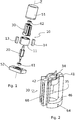
figure 1 est une vue schématique en perspective éclatée d'un moteur couple selon un mode de réalisation de l'invention, - la
figure 2 est une vue schématique en perspective d'un support de bobinage d'un moteur couple selon un mode de réalisation de l'invention, - les
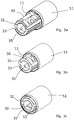
figures 3a à 3d sont des vues schématiques en perspective des différentes étapes d'insertion axiale d'un support de bobinage dans un stator d'un moteur couple selon un mode de réalisation de l'invention, - la
figure 4 est une vue schématique en perspective d'un stator d'un moteur couple selon un mode de réalisation de l'invention, - la
figure 5 est une vue schématique en perspective d'un support de bobinage équipé de bobines statoriques d'un moteur couple selon un mode de réalisation. - Sur les figures, les échelles et les proportions ne sont pas strictement respectées et ce, à des fins d'illustration et de clarté. Dans toute la description détaillée qui suit en référence aux figures, sauf indication contraire, chaque élément du moteur couple est décrit tel qu'il est agencé lorsque le moteur couple est assemblé. En outre, les éléments identiques, similaires ou analogues sont désignés par les mêmes références dans toutes les figures. Les termes axial et radial sont utilisés à titre non limitatif en référence à l'axe principal Z le long duquel s'étend le moteur couple, représenté notamment sur la
figure 1 . Enfin, pour un élément donné, les termes intérieur et extérieur ou périphérique sont utilisés pour désigner respectivement les parties de l'élément voisines de l'axe principal Z ou éloignées de l'axe principal Z. - Un moteur couple selon l'invention comprend, tel que représenté sur la
figure 1 , un stator 10 et un rotor 20 s'étendant le long d'un même axe central Z. - Le stator 10 selon le mode de réalisation des figures comprend, tel que représenté notamment sur la
figure 4 , un corps magnétique monobloc 11, une paire de dents 12 radiales s'étendant le long de l'axe central Z et qui définissent entre elles deux encoches 15, 16 de réception de bobines statoriques, et deux aimants permanents 13, 14 portés latéralement par le corps magnétique monobloc 11. - Le moteur couple selon l'invention comprend en outre un support 30 de bobinage des bobines statoriques 32, 33 comprenant un corps creux 34 qui s'étend le long de l'axe central Z.
- Selon le mode de réalisation des figures, ce support 30 est formé d'un seul tenant. Cela étant, selon d'autres modes de réalisation, le support 30 peut être formé d'une ou plusieurs pièces assemblées les unes aux autres par des moyens d'assemblage.
- Selon le mode de réalisation des figures, le corps creux 34 définit en son centre une enceinte 35 de réception du rotor 20. Cette enceinte 35 débouche à chaque extrémité axiale du corps creux 34 de sorte que le rotor 20 puisse être logé dans l'enceinte par une extrémité axiale du corps creux au cours des opérations de montage du moteur couple.
- Le support 30 comprend, tel que représenté sur la
figure 2 , des logements 41, 42 de réception des bobines statoriques 32, 33. Ces bobines 32, 33 s'étendent dans des plans parallèles à l'axe central Z. - La
figure 2 illustre le support 30 libre de toutes bobines 32, 33 statoriques et lafigure 5 illustre le support 30 équipé des bobines 32, 33 statoriques. - Le support 30, une fois équipé des bobines statoriques 32, 33 est conformé aux encoches 15, 16 de réception du corps magnétique 11 du stator, formées entre les dents radiales du corps magnétique 11 du stator.
- Ainsi, l'intégration des bobines statoriques 32, 33 dans le stator 10 consiste à insérer axialement, dans ledit corps magnétique monobloc 11 du stator, le support 30 équipé desdites bobines statoriques 32, 33.
- Les différentes étapes mises en oeuvre par un procédé d'assemblage d'un moteur couple selon l'invention sont schématiquement représentées par les
figures 3a à 3d . Sur ces figures, le corps magnétique monobloc 11 est déjà inséré dans un carter 51. - Sur la
figure 3a , le support 30 de bobinage équipé des bobines 32, 33 statoriques entre dans le corps magnétique monobloc 11. - Sur la
figure 3b , le support 30 de bobinage est partiellement inséré dans le corps magnétique monobloc 11. - Sur la
figure 3c , le support de bobinage est totalement inséré dans le corps magnétique monobloc 11. Les bobines 32, 33 statoriques sont donc en place entre les dents radiales du stator. Cette mise en place des bobines 32, 33 statoriques a été obtenue uniquement par un déplacement axial du support de bobinage. - Sur la
figure 3d , le rotor 20 a été inséré axialement dans l'enceinte 35 du support 30 de bobinage. La dernière étape de l'assemblage non représentée sur les figures consiste à équiper le moteur d'un fil d'alimentation et à visser un socle 52 sur le carter 51 du moteur. - L'assemblage d'un moteur couple selon l'invention est donc simplifié en permettant le montage des bobines statoriques 32, 33 sur le support 30, puis l'insertion du support équipé de bobines dans le stator. Le montage des bobines statoriques 32, 33 dans les logements 41, 42 de réception peut être réalisé par la mise en oeuvre d'une chaine automatisée de montage ce qui simplifie et accélère les opérations de montage par rapport à des opérations manuelles. De même, les opérations d'insertion axiale du support de bobinage dans le corps magnétique monobloc du stator et l'insertion axiale du rotor peuvent être automatisées.
- En outre, le support de bobinage équipé des bobines étant conformé aux encoches 15, 16 du stator, les performances diélectriques du moteur couple selon l'invention sont améliorées par rapport aux moteurs couples de l'art antérieur.
- Le recours à un support de bobinage permet également de minimiser la distance radiale séparant les dents du stator et du rotor et formant l'entrefer du moteur. Cet entrefer optimisé permet de fournir un moteur couple présentant des performances électromécaniques améliorées par rapport aux solutions antérieures
- De préférence, le support de bobinage est amagnétique et isolant électriquement. Il est par exemple formé en céramique.
- Un tel support en céramique permet de ne pas perturber le champ magnétique généré par les bobines et les aimants, dans l'entrefer du moteur, ce qui contribue à améliorer les performances d'un moteur couple selon ce mode de réalisation.
- Selon un mode de réalisation de l'invention, les bobines statoriques 32, 33 sont formées à partir de fils revêtus d'isolant en céramique. Le moteur couple selon l'invention n'étant plus soumis aux risques de détérioration des bobines par des manipulations complexes d'insertion des bobines dans le stator, un moteur couple peut comprendre selon un mode de réalisation avantageux des fils revêtus de céramique.
- Cela permet au moteur couple selon ce mode de réalisation de l'invention d'être utilisé dans des environnements moteurs (qui peuvent présenter des températures de l'ordre de 450°C) sans nécessiter l'adjonction d'un moyen de ventilation spécifique du moteur couple.
- Le moteur couple selon le mode de réalisation des figures comprend également un carter 51 et un socle 52. Le carter 51 et le socle 52 sont configurés pour pouvoir être solidarisés l'un à l'autre de manière à enfermer les différents éléments du moteur couple. Pour ce faire, le carter 51 peut comprendre, selon un mode de réalisation non représenté sur les figures des languettes radiales dans lesquelles sont ménagées des orifices de passage d'éléments de visserie en regard d'orifices conjugués formées dans le socle 52. Bien entendu, d'autres moyens d'assemblage entre le carter 51 et le socle 52 peuvent être prévus sans modifier l'objet de l'invention. Il peut s'agir de filetages ménagés sur la paroi périphérique du carter 51 et conjugués à des filetages ménagés sur le socle 52. Il peut s'agir de moyens d'encliquetage ou tous moyens équivalents.
- Le moteur couple comprend également des paliers 61, 62 du rotor. Selon un mode de réalisation de l'invention, ces paliers 61, 62 sont directement portés par le support 30 de bobinage, ce qui limite le nombre de pièces du moteur couple et facilite son montage.
- Le support de bobinage comprend également et tel que représenté sur les
figures 2 et5 , un compartiment 68 périphérique de connexion des bobinages statoriques avec un fil d'alimentation du moteur couple. - Ce compartiment 68 périphérique est formé, selon le mode de réalisation des figures, dans une aile latérale du support de bobinage qui s'étend le long de l'axe central entre les logements de réception 41, 42 des bobines statoriques. Ce compartiment 68 présente au moins une première ouverture configurée pour recevoir un fil d'alimentation du moteur couple et une deuxième ouverture configurée pour recevoir une extrémité des fils des bobines statoriques. Cette deuxième ouverture destinée à recevoir le fil des bobines statoriques est par exemple formée au niveau d'une paroi interne du compartiment et la première ouverture est par exemple formée au niveau d'une paroi externe du compartiment. Selon un mode de réalisation, ce compartiment 68 périphérique est configuré pour recevoir une fiche d'alimentation électrique conformée à une fiche de bobinage configurée pour recevoir une extrémité des fils des bobines statoriques de telle sorte que l'insertion de la fiche d'alimentation dans le compartiment assure spontanément la connexion électrique avec les fils des bobines statoriques reliés à la fiche de bobinage.
- Le support de bobinage comprend également et tel que représenté sur les
figures 2 et5 , deux orifices 64 ménagés au voisinage l'un de l'autre dans la paroi périphérique du support de bobinage et formant des moyens de guidage et de maintien d'un fil d'alimentation du moteur couple. Selon une autre variante, les moyens de guidage et de maintien du fil d'alimentation sont formés par une encoche aménagée au niveau de la base du support de bobinage. - Un moteur couple selon le mode de réalisation des figures permet à la fois de faciliter les opérations d'assemblage du moteur et d'améliorer les caractéristiques de tenue diélectrique.
- L'invention ne se limite pas seulement au mode de réalisation représenté sur les figures. En particulier, le support de bobinage peut présenter d'autres formes du moment qu'il est conformé au stator monobloc pour permettre une insertion axiale du support de bobinage équipé des bobines statoriques.
Claims (12)
- Moteur couple comprenant un stator (10) et un rotor (20) s'étendant le long d'un même axe central (Z), ledit stator (10) comprenant en outre un corps magnétique monobloc (11), au moins une paire de dents radiales (12) s'étendant le long de l'axe central (Z) et définissant des encoches (15, 16) de réception de bobines statoriques (32, 33) et formant un entrefer radial avec ledit rotor, au moins un aimant permanent (13, 14) porté par ledit corps magnétique monobloc (11), caractérisé en ce qu'il comprend en outre un support (30) de bobinage des bobines statoriques (32, 33) comprenant un corps creux (34) s'étendant le long de l'axe central (Z) et délimitant une enceinte (35) de réception dudit rotor (20), ledit support (30) comprenant en outre des logements (41, 42) de réception desdits bobines statoriques (32, 33) s'étendant dans des plans parallèles à l'axe central (Z), et présentant des parois radiales périphériques conformées auxdites encoches (15, 16) de réception dudit corps magnétique monobloc (11), de sorte que l'intégration des bobines statoriques (32, 33) dans ledit stator (10) consiste à insérer axialement, dans ledit corps magnétique monobloc (11), ledit support (30) de bobinage équipé desdites bobines statoriques (32, 33).
- Moteur couple selon la revendication 1, caractérisé en ce que ledit support (30) de bobinage est formé d'un seul tenant.
- Moteur couple selon l'une des revendications 1 ou 2, caractérisé en ce que ledit support (30) de bobinage est isolant électriquement, au moins au niveau des logements de réception des bobines statoriques (32, 33).
- Moteur couple selon l'une des revendications 1 à 3, caractérisé en ce que ledit support (30) de bobinage est amagnétique.
- Moteur couple selon l'une des revendications 1 à 4, caractérisé en ce que ledit support (30) de bobinage est en matériau en céramique.
- Moteur couple selon l'une des revendications 1 à 5, caractérisé en ce que ledit stator (10) comprend deux aimants permanents (13, 14) agencés en regard l'un de l'autre, une paire de dents radiales (12) définissant deux encoches (15, 16) de réception de deux bobines statoriques (32, 33) et en ce que ledit support (30) comprend deux logements (41, 42) de réception desdites bobines statoriques (32, 33).
- Moteur couple selon l'une des revendications 1 à 6, caractérisé en ce que lesdites bobines statoriques (32, 33) sont formées de fils revêtus d'un isolant d'origine minérale, tel que la céramique.
- Moteur couple selon l'une des revendications 1 à 7, caractérisé en ce que ledit support (30) porte des paliers dudit rotor (20).
- Moteur couple selon l'une des revendications 1 à 8, caractérisé en ce que ledit support (30) comprend des butées s'étendant radialement et formant des butées angulaires du rotor.
- Moteur couple selon l'une des revendications 1 à 9, caractérisé en ce que ledit support (30) comprend en outre un compartiment périphérique de connexion des bobinages statoriques avec un fil d'alimentation dudit moteur couple.
- Moteur couple selon l'une des revendications 1 à 10, caractérisé en ce que ledit support (30) comprend en outre une encoche de guidage configurée pour pouvoir guider et maintenir au moins un fil d'alimentation dudit moteur couple.
- Procédé d'assemblage d'un moteur couple comprenant un stator (10) et un rotor (20) s'étendant le long d'un même axe central (Z), ledit stator (10) comprenant en outre un corps magnétique monobloc (11), au moins une paire de dents radiales (12) s'étendant le long de l'axe central (Z) et définissant des encoches (15, 16) de réception de bobines statoriques (32, 33) et formant un entrefer radial avec ledit rotor, au moins un aimant permanent (13, 14) porté par ledit corps magnétique monobloc (11), un support (30) de bobinage des bobines statoriques (32, 33) comprenant un corps creux (34) s'étendant le long de l'axe central (Z) et délimitant une enceinte (35) de réception dudit rotor (20), ledit support (30) comprenant en outre des logements (41, 42) de réception desdits bobines statoriques (32, 33) s'étendant dans des plans parallèles à l'axe central (Z), et présentant des parois radiales périphériques conformées auxdites encoches (15, 16) de réception dudit corps magnétique monobloc (11), caractérisé en ce qu'il comprend les étapes suivantes :- montage des bobines statoriques sur le support de bobinage,- insertion axiale du support de bobinage équipé des bobines statoriques dans le corps magnétique monobloc du stator,- insertion axiale du rotor dans le corps creux du support de bobinage.
Applications Claiming Priority (1)
| Application Number | Priority Date | Filing Date | Title |
|---|---|---|---|
| FR1756764A FR3069118B1 (fr) | 2017-07-17 | 2017-07-17 | Moteur couple comprenant un support de bobinage des bobines statoriques et procede d'assemblage d'un tel moteur couple |
Publications (2)
| Publication Number | Publication Date |
|---|---|
| EP3432452A1 true EP3432452A1 (fr) | 2019-01-23 |
| EP3432452B1 EP3432452B1 (fr) | 2026-01-14 |
Family
ID=59811626
Family Applications (1)
| Application Number | Title | Priority Date | Filing Date |
|---|---|---|---|
| EP18181458.3A Active EP3432452B1 (fr) | 2017-07-17 | 2018-07-03 | Moteur couple comprenant un support de bobines statoriques et un corps magnétique y compris un aimant permanent |
Country Status (3)
| Country | Link |
|---|---|
| US (1) | US10897186B2 (fr) |
| EP (1) | EP3432452B1 (fr) |
| FR (1) | FR3069118B1 (fr) |
Families Citing this family (1)
| Publication number | Priority date | Publication date | Assignee | Title |
|---|---|---|---|---|
| CN120153561A (zh) * | 2022-09-08 | 2025-06-13 | 伍德沃德有限公司 | 电枢位移限制器 |
Citations (4)
| Publication number | Priority date | Publication date | Assignee | Title |
|---|---|---|---|---|
| DE4101666A1 (de) * | 1990-05-07 | 1991-11-14 | Licentia Gmbh | Universalmotor |
| DE19622186A1 (de) * | 1996-06-03 | 1997-12-04 | Hilti Ag | Elektromotor |
| EP1583201A2 (fr) * | 2004-03-31 | 2005-10-05 | Lg Electronics Inc. | Stator de moteur et son procédé de fabrication |
| JP2011109785A (ja) * | 2009-11-16 | 2011-06-02 | Sinfonia Technology Co Ltd | アキシャルモータ |
Family Cites Families (5)
| Publication number | Priority date | Publication date | Assignee | Title |
|---|---|---|---|---|
| US5825112A (en) * | 1992-08-06 | 1998-10-20 | Electric Power Research Institute, Inc. | Doubly salient motor with stationary permanent magnets |
| US6246561B1 (en) * | 1998-07-31 | 2001-06-12 | Magnetic Revolutions Limited, L.L.C | Methods for controlling the path of magnetic flux from a permanent magnet and devices incorporating the same |
| US6563248B2 (en) * | 2000-12-28 | 2003-05-13 | Asmo Co., Ltd. | Hybrid-magnet DC motor |
| EP1661228A4 (fr) * | 2003-09-05 | 2016-11-23 | Black & Decker Inc | Ensembles d'excitation et procede permettant de produire ceux-ci |
| JP4193859B2 (ja) * | 2006-04-04 | 2008-12-10 | トヨタ自動車株式会社 | モータおよびそのモータの通電制御装置 |
-
2017
- 2017-07-17 FR FR1756764A patent/FR3069118B1/fr active Active
-
2018
- 2018-07-03 EP EP18181458.3A patent/EP3432452B1/fr active Active
- 2018-07-17 US US16/038,148 patent/US10897186B2/en active Active
Patent Citations (4)
| Publication number | Priority date | Publication date | Assignee | Title |
|---|---|---|---|---|
| DE4101666A1 (de) * | 1990-05-07 | 1991-11-14 | Licentia Gmbh | Universalmotor |
| DE19622186A1 (de) * | 1996-06-03 | 1997-12-04 | Hilti Ag | Elektromotor |
| EP1583201A2 (fr) * | 2004-03-31 | 2005-10-05 | Lg Electronics Inc. | Stator de moteur et son procédé de fabrication |
| JP2011109785A (ja) * | 2009-11-16 | 2011-06-02 | Sinfonia Technology Co Ltd | アキシャルモータ |
Also Published As
| Publication number | Publication date |
|---|---|
| US20190020254A1 (en) | 2019-01-17 |
| FR3069118A1 (fr) | 2019-01-18 |
| FR3069118B1 (fr) | 2020-10-02 |
| EP3432452B1 (fr) | 2026-01-14 |
| US10897186B2 (en) | 2021-01-19 |
Similar Documents
| Publication | Publication Date | Title |
|---|---|---|
| FR3076674A1 (fr) | Moteur ou generatrice electromagnetique a deux rotors et quatre stators et systeme de refroidissement integre | |
| US7772731B2 (en) | Electric motor, rotary actuator and rotary apparatus | |
| EP3729609B1 (fr) | Stator de moteur ou generatrice electromagnetique avec support individuel de bobinage encliquete sur une dent associee | |
| CN109104010A (zh) | 电机 | |
| EP2573918A2 (fr) | Noyau de stator et stator | |
| EP3934060A1 (fr) | Machine électrique à bobinage concentré | |
| US20040036369A1 (en) | Sealed motor | |
| FR3006124A1 (fr) | Rotor de machine electrique a flux axial et machine electrique correspondante | |
| EP3432452B1 (fr) | Moteur couple comprenant un support de bobines statoriques et un corps magnétique y compris un aimant permanent | |
| JP2005253138A (ja) | モータ | |
| WO2015015089A2 (fr) | Rotor à griffes comportant un clip de fixation d'un fil d'extremite du bobinage et machine electrique associee | |
| EP3127217B1 (fr) | Machine electrique tournante munie de moyens de suivi ameliores de la position angulaire du rotor et ensemble de transmission correspondants | |
| US20160301291A1 (en) | Coreless motor for throttle controlling device, method for manufacturing coreless motor for throttle controlling device, and throttle controlling device | |
| CN107430961B (zh) | 起动器用电磁开关装置 | |
| EP3648314B1 (fr) | Moteur electrique a courant continu sans balai avec un couple de crantage reduit et son procede de realisation | |
| WO2016001495A2 (fr) | Moteur électromagnétique polyentrefers et à flux magnétique radial à rotor encadré par deux stators avec diminution du couple de détente | |
| FR3077414A1 (fr) | Aimant unitaire a configuration ovoide et structure d'aimant a plusieurs aimants unitaires | |
| EP3651345A1 (fr) | Procédé de réduction du couple de crantage produit par des moteurs électriques de type brushless utilises simulatenement | |
| WO2014013147A1 (fr) | Actionneur comprenant deux moteur paliers magnétiques | |
| CN208508693U (zh) | 电机、云台及无人机 | |
| EP2982022B1 (fr) | Moteur électrique à faible couple de court-circuit, dispositif de motorisation à plusieurs moteurs et procédé de fabrication d'un tel moteur | |
| JP2012147669A (ja) | 回転式アクチュエータ | |
| FR3004864A1 (fr) | Moteur electrique a circuits electriques redondants | |
| FR2858367A1 (fr) | Dispositif de positionnement angulaire d'une culasse de demarreur par rapport a son support | |
| JP4470524B2 (ja) | 密閉型モータ |
Legal Events
| Date | Code | Title | Description |
|---|---|---|---|
| PUAI | Public reference made under article 153(3) epc to a published international application that has entered the european phase |
Free format text: ORIGINAL CODE: 0009012 |
|
| STAA | Information on the status of an ep patent application or granted ep patent |
Free format text: STATUS: THE APPLICATION HAS BEEN PUBLISHED |
|
| AK | Designated contracting states |
Kind code of ref document: A1 Designated state(s): AL AT BE BG CH CY CZ DE DK EE ES FI FR GB GR HR HU IE IS IT LI LT LU LV MC MK MT NL NO PL PT RO RS SE SI SK SM TR |
|
| AX | Request for extension of the european patent |
Extension state: BA ME |
|
| STAA | Information on the status of an ep patent application or granted ep patent |
Free format text: STATUS: REQUEST FOR EXAMINATION WAS MADE |
|
| 17P | Request for examination filed |
Effective date: 20190621 |
|
| RBV | Designated contracting states (corrected) |
Designated state(s): AL AT BE BG CH CY CZ DE DK EE ES FI FR GB GR HR HU IE IS IT LI LT LU LV MC MK MT NL NO PL PT RO RS SE SI SK SM TR |
|
| STAA | Information on the status of an ep patent application or granted ep patent |
Free format text: STATUS: EXAMINATION IS IN PROGRESS |
|
| 17Q | First examination report despatched |
Effective date: 20210415 |
|
| GRAP | Despatch of communication of intention to grant a patent |
Free format text: ORIGINAL CODE: EPIDOSNIGR1 |
|
| STAA | Information on the status of an ep patent application or granted ep patent |
Free format text: STATUS: GRANT OF PATENT IS INTENDED |
|
| RIC1 | Information provided on ipc code assigned before grant |
Ipc: H02K 3/52 20060101AFI20250721BHEP Ipc: H02K 1/14 20060101ALI20250721BHEP Ipc: H02K 1/17 20060101ALI20250721BHEP Ipc: H02K 15/04 20060101ALN20250721BHEP |
|
| INTG | Intention to grant announced |
Effective date: 20250818 |
|
| GRAS | Grant fee paid |
Free format text: ORIGINAL CODE: EPIDOSNIGR3 |
|
| GRAA | (expected) grant |
Free format text: ORIGINAL CODE: 0009210 |
|
| STAA | Information on the status of an ep patent application or granted ep patent |
Free format text: STATUS: THE PATENT HAS BEEN GRANTED |
|
| AK | Designated contracting states |
Kind code of ref document: B1 Designated state(s): AL AT BE BG CH CY CZ DE DK EE ES FI FR GB GR HR HU IE IS IT LI LT LU LV MC MK MT NL NO PL PT RO RS SE SI SK SM TR |
|
| REG | Reference to a national code |
Ref country code: CH Ref legal event code: F10 Free format text: ST27 STATUS EVENT CODE: U-0-0-F10-F00 (AS PROVIDED BY THE NATIONAL OFFICE) Effective date: 20260114 Ref country code: GB Ref legal event code: FG4D Free format text: NOT ENGLISH |
|
| REG | Reference to a national code |
Ref country code: DE Ref legal event code: R096 Ref document number: 602018088547 Country of ref document: DE |
|
| REG | Reference to a national code |
Ref country code: IE Ref legal event code: FG4D Free format text: LANGUAGE OF EP DOCUMENT: FRENCH |
|
| REG | Reference to a national code |
Ref country code: NL Ref legal event code: MP Effective date: 20260114 |
|
| PG25 | Lapsed in a contracting state [announced via postgrant information from national office to epo] |
Ref country code: NL Free format text: LAPSE BECAUSE OF FAILURE TO SUBMIT A TRANSLATION OF THE DESCRIPTION OR TO PAY THE FEE WITHIN THE PRESCRIBED TIME-LIMIT Effective date: 20260114 |
|
| REG | Reference to a national code |
Ref country code: AT Ref legal event code: MK05 Ref document number: 1877790 Country of ref document: AT Kind code of ref document: T Effective date: 20260114 |
|
| PG25 | Lapsed in a contracting state [announced via postgrant information from national office to epo] |
Ref country code: RS Free format text: LAPSE BECAUSE OF FAILURE TO SUBMIT A TRANSLATION OF THE DESCRIPTION OR TO PAY THE FEE WITHIN THE PRESCRIBED TIME-LIMIT Effective date: 20260414 |
|
| PG25 | Lapsed in a contracting state [announced via postgrant information from national office to epo] |
Ref country code: ES Free format text: LAPSE BECAUSE OF FAILURE TO SUBMIT A TRANSLATION OF THE DESCRIPTION OR TO PAY THE FEE WITHIN THE PRESCRIBED TIME-LIMIT Effective date: 20260114 |
|
| PG25 | Lapsed in a contracting state [announced via postgrant information from national office to epo] |
Ref country code: PL Free format text: LAPSE BECAUSE OF FAILURE TO SUBMIT A TRANSLATION OF THE DESCRIPTION OR TO PAY THE FEE WITHIN THE PRESCRIBED TIME-LIMIT Effective date: 20260114 |
|
| PG25 | Lapsed in a contracting state [announced via postgrant information from national office to epo] |
Ref country code: GR Free format text: LAPSE BECAUSE OF FAILURE TO SUBMIT A TRANSLATION OF THE DESCRIPTION OR TO PAY THE FEE WITHIN THE PRESCRIBED TIME-LIMIT Effective date: 20260415 |
|
| REG | Reference to a national code |
Ref country code: LT Ref legal event code: MG9D |
|
| PG25 | Lapsed in a contracting state [announced via postgrant information from national office to epo] |
Ref country code: LT Free format text: LAPSE BECAUSE OF FAILURE TO SUBMIT A TRANSLATION OF THE DESCRIPTION OR TO PAY THE FEE WITHIN THE PRESCRIBED TIME-LIMIT Effective date: 20260114 |
|
| PG25 | Lapsed in a contracting state [announced via postgrant information from national office to epo] |
Ref country code: NO Free format text: LAPSE BECAUSE OF FAILURE TO SUBMIT A TRANSLATION OF THE DESCRIPTION OR TO PAY THE FEE WITHIN THE PRESCRIBED TIME-LIMIT Effective date: 20260414 |
|
| PG25 | Lapsed in a contracting state [announced via postgrant information from national office to epo] |
Ref country code: SE Free format text: LAPSE BECAUSE OF FAILURE TO SUBMIT A TRANSLATION OF THE DESCRIPTION OR TO PAY THE FEE WITHIN THE PRESCRIBED TIME-LIMIT Effective date: 20260114 Ref country code: FI Free format text: LAPSE BECAUSE OF FAILURE TO SUBMIT A TRANSLATION OF THE DESCRIPTION OR TO PAY THE FEE WITHIN THE PRESCRIBED TIME-LIMIT Effective date: 20260114 Ref country code: AT Free format text: LAPSE BECAUSE OF FAILURE TO SUBMIT A TRANSLATION OF THE DESCRIPTION OR TO PAY THE FEE WITHIN THE PRESCRIBED TIME-LIMIT Effective date: 20260114 |
|
| PG25 | Lapsed in a contracting state [announced via postgrant information from national office to epo] |
Ref country code: HR Free format text: LAPSE BECAUSE OF FAILURE TO SUBMIT A TRANSLATION OF THE DESCRIPTION OR TO PAY THE FEE WITHIN THE PRESCRIBED TIME-LIMIT Effective date: 20260114 |
|
| PG25 | Lapsed in a contracting state [announced via postgrant information from national office to epo] |
Ref country code: PT Free format text: LAPSE BECAUSE OF FAILURE TO SUBMIT A TRANSLATION OF THE DESCRIPTION OR TO PAY THE FEE WITHIN THE PRESCRIBED TIME-LIMIT Effective date: 20260514 Ref country code: IS Free format text: LAPSE BECAUSE OF FAILURE TO SUBMIT A TRANSLATION OF THE DESCRIPTION OR TO PAY THE FEE WITHIN THE PRESCRIBED TIME-LIMIT Effective date: 20260514 |
|
| PG25 | Lapsed in a contracting state [announced via postgrant information from national office to epo] |
Ref country code: LV Free format text: LAPSE BECAUSE OF FAILURE TO SUBMIT A TRANSLATION OF THE DESCRIPTION OR TO PAY THE FEE WITHIN THE PRESCRIBED TIME-LIMIT Effective date: 20260114 |
|
| PG25 | Lapsed in a contracting state [announced via postgrant information from national office to epo] |
Ref country code: BG Free format text: LAPSE BECAUSE OF FAILURE TO SUBMIT A TRANSLATION OF THE DESCRIPTION OR TO PAY THE FEE WITHIN THE PRESCRIBED TIME-LIMIT Effective date: 20260114 |