EP3432150A1 - Method and apparatus for 3d capture syncronization - Google Patents
Method and apparatus for 3d capture syncronization Download PDFInfo
- Publication number
- EP3432150A1 EP3432150A1 EP18186404.2A EP18186404A EP3432150A1 EP 3432150 A1 EP3432150 A1 EP 3432150A1 EP 18186404 A EP18186404 A EP 18186404A EP 3432150 A1 EP3432150 A1 EP 3432150A1
- Authority
- EP
- European Patent Office
- Prior art keywords
- address
- interface
- command
- camera
- camera modules
- Prior art date
- Legal status (The legal status is an assumption and is not a legal conclusion. Google has not performed a legal analysis and makes no representation as to the accuracy of the status listed.)
- Granted
Links
Images



Classifications
-
- H—ELECTRICITY
- H04—ELECTRIC COMMUNICATION TECHNIQUE
- H04N—PICTORIAL COMMUNICATION, e.g. TELEVISION
- H04N13/00—Stereoscopic video systems; Multi-view video systems; Details thereof
- H04N13/20—Image signal generators
- H04N13/204—Image signal generators using stereoscopic image cameras
- H04N13/239—Image signal generators using stereoscopic image cameras using two two-dimensional [2D] image sensors having a relative position equal to or related to the interocular distance
-
- G—PHYSICS
- G06—COMPUTING OR CALCULATING; COUNTING
- G06F—ELECTRIC DIGITAL DATA PROCESSING
- G06F3/00—Input arrangements for transferring data to be processed into a form capable of being handled by the computer; Output arrangements for transferring data from processing unit to output unit, e.g. interface arrangements
-
- G—PHYSICS
- G06—COMPUTING OR CALCULATING; COUNTING
- G06F—ELECTRIC DIGITAL DATA PROCESSING
- G06F13/00—Interconnection of, or transfer of information or other signals between, memories, input/output devices or central processing units
- G06F13/10—Program control for peripheral devices
- G06F13/102—Program control for peripheral devices where the program performs an interfacing function, e.g. device driver
-
- G—PHYSICS
- G06—COMPUTING OR CALCULATING; COUNTING
- G06F—ELECTRIC DIGITAL DATA PROCESSING
- G06F13/00—Interconnection of, or transfer of information or other signals between, memories, input/output devices or central processing units
- G06F13/14—Handling requests for interconnection or transfer
- G06F13/20—Handling requests for interconnection or transfer for access to input/output bus
- G06F13/28—Handling requests for interconnection or transfer for access to input/output bus using burst mode transfer, e.g. direct memory access DMA, cycle steal
-
- G—PHYSICS
- G06—COMPUTING OR CALCULATING; COUNTING
- G06F—ELECTRIC DIGITAL DATA PROCESSING
- G06F13/00—Interconnection of, or transfer of information or other signals between, memories, input/output devices or central processing units
- G06F13/38—Information transfer, e.g. on bus
- G06F13/42—Bus transfer protocol, e.g. handshake; Synchronisation
- G06F13/4282—Bus transfer protocol, e.g. handshake; Synchronisation on a serial bus, e.g. I2C bus, SPI bus
-
- G—PHYSICS
- G06—COMPUTING OR CALCULATING; COUNTING
- G06F—ELECTRIC DIGITAL DATA PROCESSING
- G06F13/00—Interconnection of, or transfer of information or other signals between, memories, input/output devices or central processing units
- G06F13/38—Information transfer, e.g. on bus
- G06F13/42—Bus transfer protocol, e.g. handshake; Synchronisation
- G06F13/4282—Bus transfer protocol, e.g. handshake; Synchronisation on a serial bus, e.g. I2C bus, SPI bus
- G06F13/4291—Bus transfer protocol, e.g. handshake; Synchronisation on a serial bus, e.g. I2C bus, SPI bus using a clocked protocol
-
- H—ELECTRICITY
- H04—ELECTRIC COMMUNICATION TECHNIQUE
- H04N—PICTORIAL COMMUNICATION, e.g. TELEVISION
- H04N13/00—Stereoscopic video systems; Multi-view video systems; Details thereof
- H04N13/20—Image signal generators
- H04N13/296—Synchronisation thereof; Control thereof
-
- H—ELECTRICITY
- H04—ELECTRIC COMMUNICATION TECHNIQUE
- H04N—PICTORIAL COMMUNICATION, e.g. TELEVISION
- H04N23/00—Cameras or camera modules comprising electronic image sensors; Control thereof
- H04N23/90—Arrangement of cameras or camera modules, e.g. multiple cameras in TV studios or sports stadiums
-
- G—PHYSICS
- G06—COMPUTING OR CALCULATING; COUNTING
- G06F—ELECTRIC DIGITAL DATA PROCESSING
- G06F2213/00—Indexing scheme relating to interconnection of, or transfer of information or other signals between, memories, input/output devices or central processing units
- G06F2213/0016—Inter-integrated circuit (I2C)
Definitions
- the present application relates generally to digital cameras for three-dimensional, 3D, image capture, and more specifically, to methods and apparatuses for synchronization of camera modules for 3D image capture.
- the lenses of the eyes in a healthy human being project slightly different pictures onto the retinas, which are then transformed, by the brain, into a spatial representation.
- the actual strereoscopic spatial observation is a result of this perception through both eyes.
- a stereoscopic display creates a 3D illusion with a pair of 2D images, one for the left eye and the other for the right eye, representing two perspectives of the same object, with a minor deviation similar to the perspectives that both eyes naturally receive in binocular vision.
- the viewer's brain merges the pair of images and extracts depth information from the slightly different images.
- a stereo camera is a type of camera with two or more lenses.
- the distance between the lenses in a typical stereo camera roughly corresponds to the distance between human eyes.
- strereo cameras that were developed to use 135 film with separate film frame for each lens.
- digital stereo cameras digital 3D compact cameras
- Lens unit consists of one or more lenses. It is also possible to have 3D camera where single camera module is used with specific 3D lens unit for capturing 3D images. However in those devices the lens unit has typically large physical size.
- an apparatus which comprises a first interface that is addressable by a first address and a second interface that is addressable by a second address.
- the first address is a unique address and the second address is shared address, shared with other peripheral devices of the same type connected to the same bus.
- the first interface addressed with the unique address is configured to receive individual commands and the second interface with the shared address is configured to receive group commands.
- a system which comprises a host device and at least two peripheral devices comprising a first interface that is addressable by a first address, and a second interface that is addressable by the second address.
- a method for receiving a first command via a first interface addressable by a first address, and receiving a second command via a second interface addressable by a second address.
- Figure 1 shows an example of an electrical interface between a camera module 10 and a host device 12.
- the electrical interface comprises data transmission and control interfaces.
- the data transmission interface 18 is a unidirectional interface with data and clock, or strobe, signals. This interface may be for example MIPI CSI-2. This interface is used for transferring image data from camera module 10 to host device 12.
- the control interface 16 is a bi-directional interface for controlling the camera module 10.
- Control interface 16 may be a camera control interface, CCI, which may be compatible with an inter-integrated circuit, I 2 C, bus specification, for example.
- Bus 14 which may be for example an I 2 C-bus or a bus conforming to another standard, physically consists in the illustrated example of two active wires and a ground connection.
- Two wires, serial data, SDA, and serial clock, SCL, carry information between the devices connected to the bus.
- Each device connected to the bus may be recognized by a unique address.
- a master/slave relationship may exist between devices connected to the bus; a master is the device which initiates a data transfer on the bus and generates the clock signals to permit that transfer. At that time, any device addressed is considered a slave.
- host device 12 is considered a master, or transmitter, and camera module 10 is considered a slave, or receiver.
- the CCI 16 is capable of handling several slaves but multi-master mode is not necessarily supported.
- Figure 2 shows a system comprising two peripheral devices (slaves), in this example camera modules 20a and 20b, connected to the host device 22 (master) via the bus 24, according to an embodiment of the invention.
- slaves in this example camera modules 20a and 20b
- the host device 22 master
- bus 24 the bus 24
- signal lines separate from the bus 14, data, clock/strobe, EXTCLK, shown in Figure 1 , are omitted in Figure 2 .
- All active peripheral devices connected to the same bus 24 must have different CCI addresses so that they can be recognized by host device 22.
- peripheral devices that are used at the same time are different, for example a camera and an FM-radio, this is not a problem.
- two similar camera modules 20a and 20b may be connected to the same bus 24.
- 3D image capture there exist also other applications utilizing two cameras at the same time such as augmented reality, videos with second camera used to provide a commentary video stream overlayed to a main video stream or second cameras used as an ambient light sensors, etc. Therefore a mechanism for uniquely addressing two camera modules with identical CCI addresses is needed.
- One possible solution is described next.
- FIG. 3a illustrates an example method for changing a CCI address of a peripheral device.
- camera modules 20a and 20b are powered up by applying voltage to them, however, some voltages may be already present. Initially both camera modules 20a and 20b (and 26 if the system has more than two camera modules) may be configured to have the same CCI address. If host 22 now sent a command with camera module's CCI address to the bus 24, both (or all) camera modules 20a and 20b would receive and acknowledge the command and thus it would not be possible to read camera specific data from the camera modules as both of them would respond simultaneously. Therefore, camera modules 20a and 20b may be activated sequentially instead of activating both (or all) of them together during or after the power up.
- a first camera module 20a is activated by turning a camera reference clock signal EXTCLK on. It is noted that both (or all) camera modules 20a and 20b have separate EXTCLK lines 19. When camera module 20a is activated, in the sense that its reference clock signal is on, its address can be changed.
- a block 305 host 22 sends a change address -command to the first camera module 20a.
- the command is sent to the initial, or default, address, for example 0x20.
- the address is then changed by writing a new address, for example 0x22, to a register, for example a CCI_address_control register.
- CCI addresses of the sub-circuits may be changed by using a CCI_address_control register of the sub-circuit as shown in an optional block 307.
- the camera module 20a may be configured to send an acknowledge (ACK) signal (not shown in Figure 3a ) before taking the new address into use or in connection with taking the new address into use.
- ACK acknowledge
- the host 22 may read the CCI_address_control register to make sure that the new address has been taken into use.
- a register such as a CCI_address_control_capability register
- the CCI address change may be enabled by default and thus this step is optional and not shown separately in Figure 3a but optionally included in block 305.
- the second camera module 20b is activated by turning on its EXTCLK signal.
- the second camera module 20b can be commanded using the default, i.e. initial, address, in this example 0x20.
- the address of the second camera module 20b has to be changed using the above procedure. That is, the camera modules 20a, 20b, 26 s are activated one by one, and the default address of all but one device is changed so that when the procedure is completed all similar devices have their own unique CCI address.
- camera modules 20a and 20b can now be initialized.
- NVM non-volatile memory
- information of both (or all) camera modules 20a and 20b may be read using their unique read addresses, for example 0x23 and 0x21, respectively.
- 0x22 represents a unique write address and 0x23 a unique read address for the first camera module 20a
- correspondingly 0x20 and 0x21 respresent unique write and read addresses, respectively, for the second camera module 20b.
- the camera modules 20a and 20b may then be initialized, for example by applying viewfinder settings.
- the specifics of the initialization procedure of block 311 depend on the embodiment at hand.
- the camera modules 20a and 20b are now ready for use; they can be commanded separately and their settings can be individually adjusted because they both have a different, unique, CCI address.
- the host 22 should be able to command both camera modules 20a and 20b to start streaming, or capturing, at the same time. This could be implemented by sending commands, for example to start streaming, to camera modules 20a and 20b sequentially so that camera modules receive the commands at slightly different time instants. This may be problematic in case only a very small difference between exposures is acceptable.
- One possible solution would be implementing a dedicated bus for each camera module and sending commands simultaneously to both (each) buses.
- camera module to camera module command accuracy depends on host capabilities; bus to bus timing difference may affect the quality of 3D images.
- Another solution would be assignment of unique CCI address to each connected camera module, for example as described above.
- commands to camera modules would be sent sequentially. In this case camera module to camera module delay cannot be zero.
- Still another solution would be daisy chained connection between camera modules. This solution requires at least one custom camera module.
- camera modules 20a and 20b have a second control interface 67, which will be discussed in detail in connection with Figure 6 .
- This second interface illustrated in Figure 6 as interface 67, is used to receive shared or group commands, that is commands that both (or all) camera modules should receive at the same time.
- the CCI address of the second interface 67 is the same for both (or all) camera modules 20a and 20b, that is, it is a shared address, for example 0x30. More generally, peripheral devices of a given type may share the address of the second control interface.
- This shared address host 22 may, for example, command both camera modules 20a and 20b to start streaming for 3D image capture at the same time. Start of streaming will start the exposure of the image.
- the CCI address of the second control interface 67 may be configurable.
- FIG. 3b shows an example method for operating the second control interfaces 67 of camera modules 20a and 20b.
- second interfaces 67 are activated. The activation may be performed by using the unique address of the first control interface 66. For example, for the first camera module 20a the host uses address 0x22 to write to a register, such as 2nd_CCI_if_control register. Depending on implementation, for example, the first bit on 2nd_CCI_if_control register may be set to enable the second interface 67. Initially the second interface 67 may be not enabled, that is the first bit on 2nd_CCI_if_control register has a value of '0' by default upon power-up.
- the second interface 67 of the second camera module 20b is then activated by using its unique address, in this example 0x20, to write its 2nd_CCI_if_control register. If there are further camera modules 26 connected, also their second interfaces 67 may be activated in a similar manner.
- a slave device in the examples described above a camera module, may be expected to acknowledge receipt of a command from a master, in this case a host device, by transmitting an ACK signal.
- the ACK signal may be generated for example by pulling a data line low during an acknowledge clock pulse generated by the master.
- NACK non-acknowledge
- a slave device needs to signal non-acknowledge (NACK) to the master, it leaves the data line high.
- NACK non-acknowledge
- both (or all) of them would give ACK.
- the NACK is not visible to the bus master.
- host 22 may be configured to write to one camera module's control register to enable acknowledgement.
- the first camera module 20a is allowed to send ACK signals.
- the host 22 uses the unique address, for example 0x22, of the first camera module 20a to access 2nd_CCI_if_control register of the first camera module 20a.
- this bit may be set to '0' in both (or all) camera modules 2nd_CCI_if_control register, that is the default setting may be "send ACK not allowed" in all peripheral devices.
- both first and second bit of the 2nd_CCI_if_control register of the first camera module 20a may indicate that the second interface 67 is enabled and send ACK is allowed, respectively, before activating the second interface 67 of the second (and subsequent) camera module 20b. That is, blocks 321 and 323 of Figure 3b do not have to be performed as separate ordered steps in the illustrated order.
- the bits in 2nd_CCI_if_control register may be defined diffently than described above. For example, a bit value '0' may indicate that interface is enabled and/or send ACK is allowed, and other than first two bits of the register may be allocated for this purpose.Also, a value range may be employed rather than individual bits.
- host 22 may be configured to send a start streaming command to both (or all) camera modules 20a and 20b as illustrated by block 325.
- the meaning of the start streaming command may be the same as start exposure.
- the host 22 may send a start streaming command as a group command to second interfaces 67 of both (or all) camera modules 20a and 20b using the shared address (0x30).
- both (or all) camera modules check the second bit of 2nd_CCI_if_control register and the one which has a bit value in its register indicating that it is allowed to send ACK, in this example the first camera module 20a and bit value '1', sends ACK to acknowledge the group command.
- both (or all) camera modules start streaming immediately or after a fixed delay, substantially at the same time.
- Figure 4 shows an example command flow regarding the methods illustrated in Figures 3a and 3b for two camera modules 20a, 1 st Camera, and 20b, 2 nd Camera.
- Phases 1 to 8 correspond to the method of Figure 3a and phases 9 to 12 correspond to the method of Figure 3b .
- Some of the steps may be optional as described in relation to Figures 3a and 3b .
- the unique addresses of the first control interfaces 66 may be given by using some other suitable method.
- the camera modules 20a and 20b may be uniquely addressed by default so that there is no need to change initial addresses. This could be implemented for example by having camera modules with unique address value programmed to the device memory or camera module's CCI address may be changed by programming different CCI address to each camera module already in a manufacturing phase. Having camera modules with unique default addresses may, however, result in more difficult logistics or product assembly.
- a unique address may be selected from a plurality of preselectable addresses, for example by pulling a pin to high or low. This pin may be hardwired inside a camera module and controllable by some general purpose I/O (GPIO) pin outside the camera module. This solution, however, uses additional connections and is thus not preferred but remains suitable for practising the invention according to some embodiments.
- GPIO general purpose I/O
- the initial addresses may also be changed by using other methods than the one shown in Figure 3a .
- the camera modules 20a and 20b may be activated by using some other signal than the reference clock signal EXTCLK. If the camera module has an input for a dedicated enable/disable signal, e.g. XSHUTDOWN, the camera module may be activated by driving that signal high (or low, depending on an implementation).
- the start streaming -command is not the only time critical command to which the method of Figure 3b may be applied.
- group parameter hold -command it is possible to delay a camera module to taking new settings into use. In other words, it is possible to send new commands or settings to the camera module but those command or settings are not taken into use immediately.
- the settings or commands are taken into use when grouped parameter hold is set to a released state, that is the host issues a release group parameter hold -command. At that moment new settings/commands are taken into use either immediately or afterwards. For example, the settings may be delayed until next image frame boundary. In some embodiments the data stream from the camera modules continues uninterrupted during the delay.
- Figure 5a shows a first example command flow for changing exposure parameters.
- the group parameter hold -command is issued by the host 22.
- This command is addressed with the shared address (e.g. 0x30) and thus received via the second interface 67 of both camera modules 20a and 20b at the same time.
- the camera modules may responsively delay taking new commands and settings into use.
- a change exposure time -command may be sent to the shared address.
- Both camera modules 20a and 20b receive this command at the same time, and as a response exposure time of both camera modules 20a and 20b is to be changed in accordance with the command.
- the host 22 may send a change analog gain -command to the unique address (0x22 in this example) of the first camera module 20a that receives it via the first interface 66. As a response, an analog gain parameter of the first camera module 20a may to be changed.
- host 22 sends a change analog gain -command to the unique address (0x20 in this example) of the second camera module 20b that receives it via the first interface 66. As a response, an analog gain parameter of the second camera module 20b may to be changed.
- a release group parameter hold -command is issued to the shared address, and thus received via the second interface 67 of both camera modules 20a and 20b.
- both camera modules 20a and 20b will take into use earlier loaded exposure time and analog gain values and thus both cameras will use the same exposure time and a camera module specific gain for the next frame. That is, both the exposure time change and the analog gain changes are grouped to happen for the same image frame.
- a camera pair specific command grouping was used meaning that group parameter hold was used to group and synchronize exposure value change together.
- a camera specific command grouping is used.
- the group parameter hold -command is issued by the host 22. This command is addressed with the shared address (e.g. 0x30) and thus received via the second interface 67 of both camera modules 20a and 20b at the same time.
- host 22 issues a change exposure time -command to the first camera module 20a using the unique address (0x22).
- a change exposure time -command is subsequently issued to the second camera module 20b using its unique address (0x20).
- a similar procedure is applied to the change analog gain -command.
- host 22 issues a release group parameter hold -commandto the shared address, and thus it is received via the second interface 67 of both camera modules 20a and 20b..
- both camera modules 20a and 20b will use camera module specific exposure times and gains for the next image frame. This may be beneficial when capturing images with two cameras with different settings, or more generally with peripheral devices that are configured with unique, as opposed to shared, settings.
- camera modules 20a and 20b may or may not have the same exposure time. In both cases parameters changes are grouped together to happen at same time or virtually at the same time. If in above sequence a group hold -command would have been sent to unique addresses of camera modules 20a and 20b, the camera operations of first and second camera modules would have been totally independent from each other. This may be advantageous in some use cases where camera modules do not need to be synchronized to each other. In other words, according to the example embodiment of the invention camera modules may also be used independently.
- an autofocus (AF) of two camera modules may be synchronized by exploiting a second interface according to example embodiments of the invention.
- AF autofocus
- This example covers AF synchronization during streaming, that is synchronous AF with grouped parameter hold.
- lens movement may be synchronized to the image frame timings.
- two camera modules are also synchronized together.
- the group parameter hold -command is issued by the host 22. This command is addressed with the shared address (e.g. 0x30) and thus received via the second interface 67 of both camera modules 20a and 20b at the same time.
- camera module specific AF parameters may be set using unique addresses of camera modules. That is, the host issues change AF parameters -command or commands to the first camera module 20a using its unique address, for example 0x22. A change AF parameters -command or commands are subsequently issued to the second camera module 20b using its unique address, for example 0x20. These commands are received by the camera modules 20a and 20b via first interfaces 66.
- an AF trigger -command may be issued by host 22 to both camera modules 20a and 20b via second interfaces 67 to start AF strobe generation based on AF parameters, which will start lens movement after releasing group parameter hold. That is, AF trigger -command may be addressed with a shared address, for example 0x30.
- a release group parameter hold -command is issued by host 22 to the shared address (0x30), and received via the second interface 67 by both camera modules 20a and 20b.
- An alternative AF synchronization is synchronous AF without grouped parameter hold.
- lens movement may be synchronized to the image frame timings.
- camera module specific AF parameters may be set using unique addresses of camera modules 20a and 20b (e.g. 0x22 and 0x20, respectively) in the first phase. That is, a change AF parameters -command or commands are received by camera modules 20a and 20b via their first interfaces 66.
- AF trigger -command is issued by host 22 to both camera modules 20a and 20b via second interfaces 67 to start AF strobe generation that starts lens movement.
- AF trigger -command is addressed with a shared address, for example 0x30.
- AF may not be synchronized to image frame timings, but the camera modules are synchronized to each other.
- a group parameter hold -command is issued by host 22 and addressed with a shared address (e.g. 0x30) and thus received by both camera modules 20a and 20b via second interfaces 67.
- camera module specific AF parameters may be set using unique addresses of camera modules 20a and 20b (e.g.
- a change AF parameters -command is sent to camera modules 20a and 20b via first interfaces 66.
- changing AF parameters will start lens movements after releasing group parameter hold.
- a release group parameter hold -command is issued by host 22 to the shared address (0x30), and received via the second interface 67 by both camera modules 20a and 20b.
- Command flow figures 5a and 5b show only commands issued by host device 22. However, each command sent by a master (for example host 22 ) may be acknowledged by the receiving slave(s) (the camera modules 20a and 20b ). In Figures 5a and 5b these ACK signals sent by the camera modules 20a and 20b are omitted for simplicity.
- Figure 6 shows an apparatus 60 having the first interface 66 that is addressable by a unique address and the second interface 67 that is addressable by a shared address.
- the addressed commands issued by the host device 22 are received via interfaces 66 and 67, depending on the address, from a bus 64 that may be for example an I 2 C-bus or some other I 2 C compatible bus.
- the apparatus 60 further comprises registers 61 for storing control parameters.
- the registers 61 may comprise for example CCI_address_control register and 2nd_CCI_if_control register.
- Control parameters may comprise inter alia interface address parameters, interface enable/disable parameters and an acknowledge parameter indicating whether the apparatus is allowed to send the ACK signal or not.
- the apparatus 60 may also comprise a processor 65 and a memory 63 for storing e.g. image data.
- the memory 63 may also be used to store device settings and registers; the registers 61 may be located in the memory 63.
- the memory 63 may further comprise software program instructions executable by the processor 65.
- the processor 65, the memory 63, the registers 61, and the control interfaces 66 and 67 are communicatively connected to each other.
- Processor 65 may be configured, with the software program instructions stored in memory 63, to cause the apparatus to perform processes connected with embodiments of the present invention.
- a processor 65 and a memory for storing image data may be located in a host device 22 to which the apparatus 60 is communicatively connected via the bus 64.
- a memory 63 inside the apparatus 60 comprises one or more registers 61.
- the apparatus 60 may be a camera module. If the apparatus is a camera module, it may further comprise a reference clock signal input and/or enable/disable signal input, and a data transfer interface with data and clock(/strobe) outputs as shown in Figure 1 .
- peripheral devices can receive individual commands via one interface and group commands via another interface thus eliminating the need to implement two separate control buses.
- Another technical effect of one or more of the example embodiments disclosed herein is that two peripheral devices with identical initial addresses can be connected to a bus that by definition requires unique addressing.
- Embodiments of the present invention may be implemented in software, hardware, application logic or a combination of software, hardware and application logic.
- the software, application logic and/or hardware may reside on a peripheral device or on a memory, a microprocessor or a central processing unit of the peripheral device. If desired, part of the software, application logic and/or hardware may reside on a host device or on a memory, a microprocessor or a central processing unit of the host.
- the application logic, software or an instruction set is maintained on any one of various conventional computer-readable media.
- a "computer-readable medium” may be any media or means that can contain, store, communicate, propagate or transport the instructions for use by or in connection with an instruction execution system, apparatus, or device, such as a computer, with one example of a computer described and depicted in Figure 6 .
- a computer-readable medium may comprise a computer-readable storage medium that may be any media or means that can contain or store the instructions for use by or in connection with an instruction execution system, apparatus, or device, such as a computer.
- the different functions discussed herein may be performed in a different order and/or concurrently with each other. Furthermore, if desired, one or more of the above-described functions may be optional or may be combined.
Landscapes
- Engineering & Computer Science (AREA)
- Theoretical Computer Science (AREA)
- Physics & Mathematics (AREA)
- General Engineering & Computer Science (AREA)
- General Physics & Mathematics (AREA)
- Multimedia (AREA)
- Signal Processing (AREA)
- Human Computer Interaction (AREA)
- Studio Devices (AREA)
Abstract
Description
- The present application relates generally to digital cameras for three-dimensional, 3D, image capture, and more specifically, to methods and apparatuses for synchronization of camera modules for 3D image capture.
- The lenses of the eyes in a healthy human being project slightly different pictures onto the retinas, which are then transformed, by the brain, into a spatial representation. The actual strereoscopic spatial observation is a result of this perception through both eyes. A stereoscopic display creates a 3D illusion with a pair of 2D images, one for the left eye and the other for the right eye, representing two perspectives of the same object, with a minor deviation similar to the perspectives that both eyes naturally receive in binocular vision. The viewer's brain merges the pair of images and extracts depth information from the slightly different images.
- Stereoscopic, or 3D, pictures are produced in pairs, the members of a pair showing the same scene or object from slightly diffent angles that correspond to the angles of vision of the two eyes of a person looking at the object. Thus, it is necessary to take two photographs for a 3D image. This can be done with two cameras, with one camera moved quickly to two positions, or with a stereo camera configured to obtain two images.
- A stereo camera is a type of camera with two or more lenses. The distance between the lenses in a typical stereo camera roughly corresponds to the distance between human eyes. In the 1950s a number of manufacturers introduced strereo cameras that were developed to use 135 film with separate film frame for each lens. Recently, digital stereo cameras (digital 3D compact cameras) have come on the market. In digital 3D cameras there are usually two camera modules, each of them having one lens unit and one image sensor. Lens unit consists of one or more lenses. It is also possible to have 3D camera where single camera module is used with specific 3D lens unit for capturing 3D images. However in those devices the lens unit has typically large physical size..
- Various aspects of examples of the invention are set out in the claims.
- According to a first aspect of the present invention, an apparatus is described, which comprises a first interface that is addressable by a first address and a second interface that is addressable by a second address.
- In one embodiment of the invention, the first address is a unique address and the second address is shared address, shared with other peripheral devices of the same type connected to the same bus. The first interface addressed with the unique address is configured to receive individual commands and the second interface with the shared address is configured to receive group commands.
- According to a second aspect of the present invention, a system is described, which comprises a host device and at least two peripheral devices comprising a first interface that is addressable by a first address, and a second interface that is addressable by the second address.
- According to a third aspect of the present invention, a method is provided for receiving a first command via a first interface addressable by a first address, and receiving a second command via a second interface addressable by a second address.
- For a more complete understanding of example embodiments of the present invention, reference is now made to the following descriptions taken in connection with the accompanying drawings in which:
-
Figure 1 shows an example of an electrical interface between a camera module and a host device; -
Figure 2 shows a system comprising a host device and plurality of peripheral devices connected to the host device according to an embodiment of the invention; -
Figure 3a illustrates an example method for changing a CCI address of a peripheral device; -
Figure 3b illustrates an example method for operating second control interfaces of peripheral devices; -
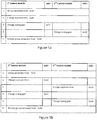
Figure 4 shows an example command flow regarding the methods illustrated inFigures 3a and 3b ; -
Figure 5a shows a first example command flow for changing exposure parameters of camera modules; -
Figure 5b shows a second example command flow for changing exposure parameters of camera modules; and -
Figure 6 shows an example of an apparatus according to an embodiment of the invention. - Example embodiments of the present invention are understood by referring to
Figures 1 through 6 of the drawings. - In 3D capture, it is crucial to capture both images at substantially the same time; especially when a target is moving or when a background comprises changing or moving objects. In digital 3D cameras with two sensors there are thus strict timing requirements. This relates mainly to camera command timings between two camera modules, as some commands have to be received at the same time or very close to that.
-
Figure 1 shows an example of an electrical interface between acamera module 10 and ahost device 12. The electrical interface comprises data transmission and control interfaces. In the example ofFigure 1 , thedata transmission interface 18 is a unidirectional interface with data and clock, or strobe, signals. This interface may be for example MIPI CSI-2. This interface is used for transferring image data fromcamera module 10 tohost device 12. Thecontrol interface 16 is a bi-directional interface for controlling thecamera module 10.Control interface 16 may be a camera control interface, CCI, which may be compatible with an inter-integrated circuit, I2C, bus specification, for example. -
Bus 14, which may be for example an I2C-bus or a bus conforming to another standard, physically consists in the illustrated example of two active wires and a ground connection. Two wires, serial data, SDA, and serial clock, SCL, carry information between the devices connected to the bus. Each device connected to the bus may be recognized by a unique address. A master/slave relationship may exist between devices connected to the bus; a master is the device which initiates a data transfer on the bus and generates the clock signals to permit that transfer. At that time, any device addressed is considered a slave. - In the example embodiment illustrated in
Figure 1 ,host device 12 is considered a master, or transmitter, andcamera module 10 is considered a slave, or receiver. In the illustrated example, the CCI 16 is capable of handling several slaves but multi-master mode is not necessarily supported. -
Figure 2 shows a system comprising two peripheral devices (slaves), in thisexample camera modules bus 24, according to an embodiment of the invention. Although in 3D capture only two camera modules are required, it is possible to connect further camera modules or other (slave)devices 26 to thesame bus 24 as illustrated inFigure 2 . For simplicity signal lines separate from thebus 14, data, clock/strobe, EXTCLK, shown inFigure 1 , are omitted inFigure 2 . - All active peripheral devices connected to the
same bus 24 must have different CCI addresses so that they can be recognized byhost device 22. When peripheral devices that are used at the same time are different, for example a camera and an FM-radio, this is not a problem. In case of a 3D camera, however, twosimilar camera modules same bus 24. In addition to 3D image capture there exist also other applications utilizing two cameras at the same time such as augmented reality, videos with second camera used to provide a commentary video stream overlayed to a main video stream or second cameras used as an ambient light sensors, etc. Therefore a mechanism for uniquely addressing two camera modules with identical CCI addresses is needed. One possible solution is described next. -
Figure 3a illustrates an example method for changing a CCI address of a peripheral device. In afirst block 301camera modules camera modules host 22 now sent a command with camera module's CCI address to thebus 24, both (or all)camera modules camera modules - In a block 303 a
first camera module 20a is activated by turning a camera reference clock signal EXTCLK on. It is noted that both (or all)camera modules camera module 20a is activated, in the sense that its reference clock signal is on, its address can be changed. - In a
block 305,host 22 sends a change address -command to thefirst camera module 20a. The command is sent to the initial, or default, address, for example 0x20. The address is then changed by writing a new address, for example 0x22, to a register, for example a CCI_address_control register. In case thefirst camera 20a includes sub-circuits, for example a separate lens driver, also CCI addresses of the sub-circuits may be changed by using a CCI_address_control register of the sub-circuit as shown in anoptional block 307. Thecamera module 20a may be configured to send an acknowledge (ACK) signal (not shown inFigure 3a ) before taking the new address into use or in connection with taking the new address into use. Thehost 22 may read the CCI_address_control register to make sure that the new address has been taken into use. Optionally, before sending the change address -command host 22 may check from a register, such as a CCI_address_control_capability register, that the CCI address of thefirst camera 20a can be changed. However, the CCI address change may be enabled by default and thus this step is optional and not shown separately inFigure 3a but optionally included inblock 305. - In
block 309 thesecond camera module 20b is activated by turning on its EXTCLK signal. As thefirst camera module 20a now has a new address (0x22) in use, thesecond camera module 20b can be commanded using the default, i.e. initial, address, in this example 0x20. However, if there are more than two camera modules connected to thesame bus 24 also the address of thesecond camera module 20b has to be changed using the above procedure. That is, thecamera modules - As shown in an
optional block 311,camera modules camera modules first camera module 20a, and correspondingly 0x20 and 0x21 respresent unique write and read addresses, respectively, for thesecond camera module 20b. Thecamera modules block 311 depend on the embodiment at hand. - The
camera modules host 22 should be able to command bothcamera modules camera modules - One possible solution would be implementing a dedicated bus for each camera module and sending commands simultaneously to both (each) buses. In this solution camera module to camera module command accuracy depends on host capabilities; bus to bus timing difference may affect the quality of 3D images. Another solution would be assignment of unique CCI address to each connected camera module, for example as described above. In this solution commands to camera modules would be sent sequentially. In this case camera module to camera module delay cannot be zero. Still another solution would be daisy chained connection between camera modules. This solution requires at least one custom camera module.
- In one example embodiment of the invention,
camera modules second control interface 67, which will be discussed in detail in connection withFigure 6 . This second interface, illustrated inFigure 6 asinterface 67, is used to receive shared or group commands, that is commands that both (or all) camera modules should receive at the same time. The CCI address of thesecond interface 67 is the same for both (or all)camera modules address host 22 may, for example, command bothcamera modules second control interface 67 may be configurable. -
Figure 3b shows an example method for operating the second control interfaces 67 ofcamera modules block 321,second interfaces 67 are activated. The activation may be performed by using the unique address of thefirst control interface 66. For example, for thefirst camera module 20a the host uses address 0x22 to write to a register, such as 2nd_CCI_if_control register. Depending on implementation, for example, the first bit on 2nd_CCI_if_control register may be set to enable thesecond interface 67. Initially thesecond interface 67 may be not enabled, that is the first bit on 2nd_CCI_if_control register has a value of '0' by default upon power-up. Thesecond interface 67 of thesecond camera module 20b is then activated by using its unique address, in this example 0x20, to write its 2nd_CCI_if_control register. If there arefurther camera modules 26 connected, also theirsecond interfaces 67 may be activated in a similar manner. - A slave device, in the examples described above a camera module, may be expected to acknowledge receipt of a command from a master, in this case a host device, by transmitting an ACK signal. The ACK signal may be generated for example by pulling a data line low during an acknowledge clock pulse generated by the master. In case a slave device needs to signal non-acknowledge (NACK) to the master, it leaves the data line high. In case of a group command that is sent to both (or all)
camera modules block 323host 22 may be configured to write to one camera module's control register to enable acknowledgement. In this example thefirst camera module 20a is allowed to send ACK signals. Thehost 22 uses the unique address, for example 0x22, of thefirst camera module 20a to access 2nd_CCI_if_control register of thefirst camera module 20a. It may set the second bit, for example, on 2nd_CCI_if_control to indicate that thefirst camera module 20a is allowed to send ACK signals to acknowledge group commands. By default this bit may be set to '0' in both (or all) camera modules 2nd_CCI_if_control register, that is the default setting may be "send ACK not allowed" in all peripheral devices. - It is also possible to set both first and second bit of the 2nd_CCI_if_control register of the
first camera module 20a to indicate that thesecond interface 67 is enabled and send ACK is allowed, respectively, before activating thesecond interface 67 of the second (and subsequent)camera module 20b. That is, blocks 321 and 323 ofFigure 3b do not have to be performed as separate ordered steps in the illustrated order. Further, the bits in 2nd_CCI_if_control register may be defined diffently than described above. For example, a bit value '0' may indicate that interface is enabled and/or send ACK is allowed, and other than first two bits of the register may be allocated for this purpose.Also, a value range may be employed rather than individual bits. - After
second interfaces 67 ofcamera modules host 22 may be configured to send a start streaming command to both (or all)camera modules block 325. The meaning of the start streaming command may be the same as start exposure. Thehost 22 may send a start streaming command as a group command tosecond interfaces 67 of both (or all)camera modules - In
block 327, both (or all) camera modules check the second bit of 2nd_CCI_if_control register and the one which has a bit value in its register indicating that it is allowed to send ACK, in this example thefirst camera module 20a and bit value '1', sends ACK to acknowledge the group command. Finally, inblock 329 both (or all) camera modules start streaming immediately or after a fixed delay, substantially at the same time. -
Figure 4 shows an example command flow regarding the methods illustrated inFigures 3a and 3b for twocamera modules Phases 1 to 8 correspond to the method ofFigure 3a and phases 9 to 12 correspond to the method ofFigure 3b . Some of the steps may be optional as described in relation toFigures 3a and 3b . - It is noted that for realizing the example embodiment shown in
Figure 3b , the method ofFigure 3a or phases 1 to 8 ofFigure 4 are not necessarily required. The unique addresses of the first control interfaces 66 may be given by using some other suitable method. For example thecamera modules - The initial addresses may also be changed by using other methods than the one shown in
Figure 3a . For example, thecamera modules - The start streaming -command is not the only time critical command to which the method of
Figure 3b may be applied. As another example, the usage of grouped parameter hold is described next. By using group parameter hold -command, it is possible to delay a camera module to taking new settings into use. In other words, it is possible to send new commands or settings to the camera module but those command or settings are not taken into use immediately. The settings or commands are taken into use when grouped parameter hold is set to a released state, that is the host issues a release group parameter hold -command. At that moment new settings/commands are taken into use either immediately or afterwards. For example, the settings may be delayed until next image frame boundary. In some embodiments the data stream from the camera modules continues uninterrupted during the delay. -
Figure 5a shows a first example command flow for changing exposure parameters. In a first phase, the group parameter hold -command is issued by thehost 22. This command is addressed with the shared address (e.g. 0x30) and thus received via thesecond interface 67 of bothcamera modules camera modules camera modules phase 3, thehost 22 may send a change analog gain -command to the unique address (0x22 in this example) of thefirst camera module 20a that receives it via thefirst interface 66. As a response, an analog gain parameter of thefirst camera module 20a may to be changed. In thenext phase host 22 sends a change analog gain -command to the unique address (0x20 in this example) of thesecond camera module 20b that receives it via thefirst interface 66. As a response, an analog gain parameter of thesecond camera module 20b may to be changed. In the last phase ofFigure 5a , a release group parameter hold -command is issued to the shared address, and thus received via thesecond interface 67 of bothcamera modules camera modules - In the example command flow of
Figure 5b , a camera specific command grouping is used. In a first phase, the group parameter hold -command is issued by thehost 22. This command is addressed with the shared address (e.g. 0x30) and thus received via thesecond interface 67 of bothcamera modules first camera module 20a using the unique address (0x22). A change exposure time -command is subsequently issued to thesecond camera module 20b using its unique address (0x20). A similar procedure is applied to the change analog gain -command. Finally, host 22 issues a release group parameter hold -commandto the shared address, and thus it is received via thesecond interface 67 of bothcamera modules camera modules camera modules camera modules - As another example, an autofocus (AF) of two camera modules may be synchronized by exploiting a second interface according to example embodiments of the invention. In the following an example operation flow to synchronize the autofocus of two
camera modules host 22. This command is addressed with the shared address (e.g. 0x30) and thus received via thesecond interface 67 of bothcamera modules first camera module 20a using its unique address, for example 0x22. A change AF parameters -command or commands are subsequently issued to thesecond camera module 20b using its unique address, for example 0x20. These commands are received by thecamera modules host 22 to bothcamera modules second interfaces 67 to start AF strobe generation based on AF parameters, which will start lens movement after releasing group parameter hold. That is, AF trigger -command may be addressed with a shared address, for example 0x30. Finally, a release group parameter hold -command is issued byhost 22 to the shared address (0x30), and received via thesecond interface 67 by bothcamera modules - An alternative AF synchronization is synchronous AF without grouped parameter hold. Also in this example lens movement may be synchronized to the image frame timings. In this example in addition two camera modules are also synchronized together In this case, camera module specific AF parameters may be set using unique addresses of
camera modules camera modules first interfaces 66. In a second phase, AF trigger -command is issued byhost 22 to bothcamera modules second interfaces 67 to start AF strobe generation that starts lens movement. That is, AF trigger -command is addressed with a shared address, for example 0x30. Still another alternative is asynchoronous AF that happens simultaneously with grouped parameter hold. In asynchronous AF mode, AF may not be synchronized to image frame timings, but the camera modules are synchronized to each other. In this example, a group parameter hold -command is issued byhost 22 and addressed with a shared address (e.g. 0x30) and thus received by bothcamera modules camera modules camera modules host 22 to the shared address (0x30), and received via thesecond interface 67 by bothcamera modules - Command flow
figures 5a and 5b show only commands issued byhost device 22. However, each command sent by a master (for example host 22) may be acknowledged by the receiving slave(s) (thecamera modules Figures 5a and 5b these ACK signals sent by thecamera modules -
Figure 6 shows anapparatus 60 having thefirst interface 66 that is addressable by a unique address and thesecond interface 67 that is addressable by a shared address. The addressed commands issued by the host device 22 (not shown inFigure 6 ) are received viainterfaces bus 64 that may be for example an I2C-bus or some other I2C compatible bus. Theapparatus 60 further comprisesregisters 61 for storing control parameters. Theregisters 61 may comprise for example CCI_address_control register and 2nd_CCI_if_control register. Control parameters may comprise inter alia interface address parameters, interface enable/disable parameters and an acknowledge parameter indicating whether the apparatus is allowed to send the ACK signal or not. Theapparatus 60 may also comprise aprocessor 65 and amemory 63 for storing e.g. image data. Thememory 63 may also be used to store device settings and registers; theregisters 61 may be located in thememory 63. Thememory 63 may further comprise software program instructions executable by theprocessor 65. Theprocessor 65, thememory 63, theregisters 61, and the control interfaces 66 and 67 are communicatively connected to each other.Processor 65 may be configured, with the software program instructions stored inmemory 63, to cause the apparatus to perform processes connected with embodiments of the present invention. Alternatively, aprocessor 65 and a memory for storing image data may be located in ahost device 22 to which theapparatus 60 is communicatively connected via thebus 64. In this case, amemory 63 inside theapparatus 60 comprises one or more registers 61. - The
apparatus 60 may be a camera module. If the apparatus is a camera module, it may further comprise a reference clock signal input and/or enable/disable signal input, and a data transfer interface with data and clock(/strobe) outputs as shown inFigure 1 . - Although the example embodiments of the invention has been described in relation to camera modules it is noted that the invention is not limited to them but may be applied also to any I2C compatible peripheral devices if unique and shared addressing is required.
- Without in any way limiting the scope, interpretation, or application of the claims appearing below, a technical effect of one or more of the example embodiments disclosed herein is that peripheral devices can receive individual commands via one interface and group commands via another interface thus eliminating the need to implement two separate control buses. Another technical effect of one or more of the example embodiments disclosed herein is that two peripheral devices with identical initial addresses can be connected to a bus that by definition requires unique addressing.
- Embodiments of the present invention may be implemented in software, hardware, application logic or a combination of software, hardware and application logic. The software, application logic and/or hardware may reside on a peripheral device or on a memory, a microprocessor or a central processing unit of the peripheral device. If desired, part of the software, application logic and/or hardware may reside on a host device or on a memory, a microprocessor or a central processing unit of the host. In an example embodiment, the application logic, software or an instruction set is maintained on any one of various conventional computer-readable media. In the context of this document, a "computer-readable medium" may be any media or means that can contain, store, communicate, propagate or transport the instructions for use by or in connection with an instruction execution system, apparatus, or device, such as a computer, with one example of a computer described and depicted in
Figure 6 . A computer-readable medium may comprise a computer-readable storage medium that may be any media or means that can contain or store the instructions for use by or in connection with an instruction execution system, apparatus, or device, such as a computer. - If desired, the different functions discussed herein may be performed in a different order and/or concurrently with each other. Furthermore, if desired, one or more of the above-described functions may be optional or may be combined.
- Although various aspects of the invention are set out in the independent claims, other aspects of the invention comprise other combinations of features from the described embodiments and/or the dependent claims with the features of the independent claims, and not solely the combinations explicitly set out in the claims.
- It is also noted herein that while the above describes example embodiments of the invention, these descriptions should not be viewed in a limiting sense. Rather, there are several variations and modifications which may be made without departing from the scope of the present invention as defined in the appended claims.
- This specification includes the following clauses:
- 1. An apparatus comprising:
- a first interface addressable by a first address, and
- a second interface addressable by a second address.
- 2. An apparatus of
clause 1, further comprising a clock input separate from the first interface and the second interface, the clock input configured to receive a clock signal, wherein the apparatus is configured to receive the first address responsive to the clock signal. - 3. An apparatus of
clause - 4. An apparatus of
clause 3, wherein said shared address is the same for each of at least two peripheral devices of the same type connected to the same bus. - 5. An apparatus of any of
clauses 1 to 4, wherein the first interface is configured to receive individual commands, and the second interface is configured to receive group commands. - 6. An apparatus of any of the preceding clauses, wherein the apparatus is inter-integrated circuit -bus compatible.
- 7. An apparatus of any of the preceding clauses, wherein the apparatus is a camera module.
- 8. An apparatus of
clause 7, wherein the first interface and the second interface are camera control interfaces. - 9. A system comprising:
- a host device;
- at least two peripheral devices according to any of
clauses 1 to 8.
- 10. A system of
clause 9, wherein said at least two peripheral devices are connected to the host device via an inter-integrated circuit -bus. - 11. A system of
clause - 12. A system of any of
clauses 9 to 11, wherein only one of the at least two peripheral devices is enabled to send an acknkowledge signal to the host device as a response to a group command. - 13. A method comprising:
- receiving a first command via a first interface addressable by a first address;
- receiving a second command via a second interface addressable by a second address.
- 14. A method of clause 13, further comprising:
- receiving a clock signal at a clock input, and
- subsequently receiving via the first interface a unique address to replace said first address.
- 15. A method of clause 13, wherein the second address is a shared address, the shared address being the same for each of at least two peripheral devices of the same type connected to the same bus.
- 16. A method of any of clauses 13 to 15, further comprising storing an indication indicating whether a peripheral device is an acknkowledging peripheral device, and
in case the peripheral device is an acknowledging peripheral device, sending an acknowledge signal in reponse to a group command received via the second interface. - 17. A method of
clause 16, wherein the group command is received at the same time in each of at least two peripheral devices of the same type connected to the same bus. - 18. A non-transitory computer-readable medium that contains software program instructions, where execution of the software program instructions by at least one data processor results in performance of operations that comprise execution of a method of any one of clauses 13 through 17.
Claims (15)
- A method comprising:receiving a first command via a first interface addressable by a first address; andreceiving a second command via a second interface addressable by a second address.
- A method of claim 1, further comprising:receiving a clock signal at a clock input, wherein the first address is received responsive to the clock signal.
- A method of claim 2, wherein the clock input is separate from the first interface and the second interface.
- A method of claim 1, further comprising receiving via the first interface a unique address to replace the first address.
- A method of claim 1, wherein the second address is a shared address.
- A method of claim 5, wherein the shared address being the same for each of at least two peripheral devices of the same type connected to the same bus.
- A method of claim 1 further comprising storing an indication indicating whether a peripheral device is an acknkowledging peripheral device, and
in case the peripheral device is an acknowledging peripheral device, sending an acknowledge signal in reponse to a group command received via the second interface. - A method of claim 7, wherein the group command is received at the same time in each of at least two peripheral devices of the same type connected to the same bus.
- A method of claim 1, wherein the first interface is configured to receive individual commands, and the second interface is configured to receive group commands.
- A method of claim 1, wherein the first interface and the second interface are camera control interfaces.
- An apparatus comprising means configured to perform method as claimed in any of the claims 1 to 10.
- An apparatus of claim 11, wherein the apparatus is inter-integrated circuit - bus compatible.
- An apparatus of claim 11 or 12, wherein the apparatus is a camera module.
- A system comprising:a host device;at least two peripheral devices according to any of claims 11 to 13.
- A computer program product comprising program instructions which when executed by an apparatus cause the apparatus to perform method of any of claims 1 - 10.
Priority Applications (1)
| Application Number | Priority Date | Filing Date | Title |
|---|---|---|---|
| EP18186404.2A EP3432150B1 (en) | 2010-12-13 | 2010-12-13 | Method and apparatus for 3d capture synchronisation |
Applications Claiming Priority (3)
| Application Number | Priority Date | Filing Date | Title |
|---|---|---|---|
| EP18186404.2A EP3432150B1 (en) | 2010-12-13 | 2010-12-13 | Method and apparatus for 3d capture synchronisation |
| PCT/FI2010/051011 WO2012080556A1 (en) | 2010-12-13 | 2010-12-13 | Method and apparatus for 3d capture syncronization |
| EP10803374.7A EP2652629B1 (en) | 2010-12-13 | 2010-12-13 | Method and apparatus for 3d capture syncronization |
Related Parent Applications (2)
| Application Number | Title | Priority Date | Filing Date |
|---|---|---|---|
| EP10803374.7A Division EP2652629B1 (en) | 2010-12-13 | 2010-12-13 | Method and apparatus for 3d capture syncronization |
| EP10803374.7A Division-Into EP2652629B1 (en) | 2010-12-13 | 2010-12-13 | Method and apparatus for 3d capture syncronization |
Publications (2)
| Publication Number | Publication Date |
|---|---|
| EP3432150A1 true EP3432150A1 (en) | 2019-01-23 |
| EP3432150B1 EP3432150B1 (en) | 2021-01-20 |
Family
ID=44513368
Family Applications (2)
| Application Number | Title | Priority Date | Filing Date |
|---|---|---|---|
| EP18186404.2A Active EP3432150B1 (en) | 2010-12-13 | 2010-12-13 | Method and apparatus for 3d capture synchronisation |
| EP10803374.7A Active EP2652629B1 (en) | 2010-12-13 | 2010-12-13 | Method and apparatus for 3d capture syncronization |
Family Applications After (1)
| Application Number | Title | Priority Date | Filing Date |
|---|---|---|---|
| EP10803374.7A Active EP2652629B1 (en) | 2010-12-13 | 2010-12-13 | Method and apparatus for 3d capture syncronization |
Country Status (5)
| Country | Link |
|---|---|
| US (3) | US20140320608A1 (en) |
| EP (2) | EP3432150B1 (en) |
| KR (1) | KR101571942B1 (en) |
| CN (2) | CN110072096A (en) |
| WO (1) | WO2012080556A1 (en) |
Families Citing this family (26)
| Publication number | Priority date | Publication date | Assignee | Title |
|---|---|---|---|---|
| EP3432150B1 (en) | 2010-12-13 | 2021-01-20 | Nokia Technologies Oy | Method and apparatus for 3d capture synchronisation |
| US9244694B2 (en) * | 2012-12-27 | 2016-01-26 | Intel Corporation | Executing a command within a transport mechanism based on a get and set architecture |
| US11019258B2 (en) | 2013-08-21 | 2021-05-25 | Verizon Patent And Licensing Inc. | Aggregating images and audio data to generate content |
| US9451162B2 (en) | 2013-08-21 | 2016-09-20 | Jaunt Inc. | Camera array including camera modules |
| US9710410B2 (en) * | 2013-10-31 | 2017-07-18 | Qualcomm Incorporated | Camera control slave devices with multiple slave device identifiers |
| US9402018B2 (en) * | 2013-12-17 | 2016-07-26 | Amazon Technologies, Inc. | Distributing processing for imaging processing |
| JP2015128254A (en) * | 2013-12-27 | 2015-07-09 | ソニー株式会社 | Information processor, information processing system, information processing method and program |
| US9911454B2 (en) | 2014-05-29 | 2018-03-06 | Jaunt Inc. | Camera array including camera modules |
| US11108971B2 (en) | 2014-07-25 | 2021-08-31 | Verzon Patent and Licensing Ine. | Camera array removing lens distortion |
| US9774887B1 (en) | 2016-09-19 | 2017-09-26 | Jaunt Inc. | Behavioral directional encoding of three-dimensional video |
| US10440398B2 (en) | 2014-07-28 | 2019-10-08 | Jaunt, Inc. | Probabilistic model to compress images for three-dimensional video |
| US9363569B1 (en) | 2014-07-28 | 2016-06-07 | Jaunt Inc. | Virtual reality system including social graph |
| US10701426B1 (en) | 2014-07-28 | 2020-06-30 | Verizon Patent And Licensing Inc. | Virtual reality system including social graph |
| RU2693911C1 (en) | 2016-02-26 | 2019-07-05 | Майкро Моушн, Инк. | Data exchange with two or more slave devices |
| WO2018048838A1 (en) * | 2016-09-06 | 2018-03-15 | Apple Inc. | Still image stabilization/optical image stabilization synchronization in multi-camera image capture |
| US11032536B2 (en) | 2016-09-19 | 2021-06-08 | Verizon Patent And Licensing Inc. | Generating a three-dimensional preview from a two-dimensional selectable icon of a three-dimensional reality video |
| US11032535B2 (en) | 2016-09-19 | 2021-06-08 | Verizon Patent And Licensing Inc. | Generating a three-dimensional preview of a three-dimensional video |
| US10681341B2 (en) | 2016-09-19 | 2020-06-09 | Verizon Patent And Licensing Inc. | Using a sphere to reorient a location of a user in a three-dimensional virtual reality video |
| US10742959B1 (en) | 2017-12-29 | 2020-08-11 | Perceive Corporation | Use of machine-trained network for misalignment-insensitive depth perception |
| US10694167B1 (en) | 2018-12-12 | 2020-06-23 | Verizon Patent And Licensing Inc. | Camera array including camera modules |
| US10750077B1 (en) | 2019-02-20 | 2020-08-18 | Himax Imaging Limited | Camera system with multiple camera |
| TWI702566B (en) * | 2019-03-20 | 2020-08-21 | 恆景科技股份有限公司 | Camera system |
| FR3097987A1 (en) * | 2019-06-26 | 2021-01-01 | STMicroelectronics (Alps) SAS | METHOD OF ADDRESSING AN INTEGRATED CIRCUIT ON A BUS AND CORRESPONDING DEVICE |
| DE102019126814A1 (en) * | 2019-10-07 | 2021-04-08 | Connaught Electronics Ltd. | Electronic control unit |
| CN111050048B (en) * | 2019-12-27 | 2021-09-07 | 重庆金山医疗技术研究院有限公司 | Image acquisition apparatus, method and storage medium |
| CN112463662B (en) * | 2020-12-16 | 2024-04-05 | 福州创实讯联信息技术有限公司 | Method and terminal for user mode control of I2C equipment |
Citations (4)
| Publication number | Priority date | Publication date | Assignee | Title |
|---|---|---|---|---|
| US20030149824A1 (en) * | 2002-02-06 | 2003-08-07 | Smith Robert B. | Method and apparatus for addressing multiple devices simultaneously over a data bus |
| KR20070035265A (en) * | 2005-09-27 | 2007-03-30 | (주)대인테크 | Control device for parts having a common address using I2C communication |
| US7685320B1 (en) * | 2003-04-11 | 2010-03-23 | Zilker Labs, Inc. | Autonomous sequencing and fault spreading |
| US7743175B1 (en) * | 2008-07-17 | 2010-06-22 | Xilinx, Inc. | Methods of initializing routing structures in integrated circuits |
Family Cites Families (56)
| Publication number | Priority date | Publication date | Assignee | Title |
|---|---|---|---|---|
| JPH03238539A (en) * | 1990-02-15 | 1991-10-24 | Nec Corp | Memory access controller |
| US5280281A (en) * | 1990-10-25 | 1994-01-18 | Pioneer Electronic Corporation | Method of and system for data communication in communication network on automobile |
| US5377325A (en) | 1992-04-21 | 1994-12-27 | Acer Incorporated | Bidirectional wait control between host module and slave module |
| US5960155A (en) * | 1993-08-09 | 1999-09-28 | Ricoh Company, Ltd. | Electronic still camera |
| US5535349A (en) * | 1994-06-09 | 1996-07-09 | Motorola, Inc. | Data processing system and method for providing chip selects to peripheral devices |
| EP0715453B1 (en) * | 1994-11-28 | 2014-03-26 | Canon Kabushiki Kaisha | Camera controller |
| US5832298A (en) | 1995-05-30 | 1998-11-03 | Canon Kabushiki Kaisha | Adaptive graphical user interface for a network peripheral |
| US6025840A (en) | 1995-09-27 | 2000-02-15 | Cirrus Logic, Inc. | Circuits, systems and methods for memory mapping and display control systems using the same |
| US5974475A (en) | 1997-06-24 | 1999-10-26 | Microchip Technology Incorporated | Method for flexible multiple access on a serial bus by a plurality of boards |
| KR19990027317A (en) * | 1997-09-29 | 1999-04-15 | 윤종용 | Composite image processing device |
| US6629172B1 (en) | 1998-12-14 | 2003-09-30 | Micron Technology, Inc. | Multi-chip addressing for the I2C bus |
| JP3838809B2 (en) * | 1999-03-30 | 2006-10-25 | 川崎マイクロエレクトロニクス株式会社 | Serial data transfer device |
| GB2355612A (en) | 1999-10-19 | 2001-04-25 | Tricorder Technology Plc | Image processing arrangement producing a combined output signal from input video signals. |
| US20050174473A1 (en) | 1999-11-18 | 2005-08-11 | Color Kinetics, Inc. | Photography methods and systems |
| US6950121B2 (en) | 1999-12-28 | 2005-09-27 | Vrex, Inc. | 3D camera |
| US6864911B1 (en) | 2000-10-26 | 2005-03-08 | Hewlett-Packard Development Company, L.P. | Linkable digital cameras for an image capture system |
| US6745270B1 (en) | 2001-01-31 | 2004-06-01 | International Business Machines Corporation | Dynamically allocating I2C addresses using self bus switching device |
| WO2003014947A1 (en) | 2001-08-02 | 2003-02-20 | Matsushita Electric Industrial Co., Ltd. | Host apparatus, electronic device, and transmission system control method |
| US7239345B1 (en) * | 2001-10-12 | 2007-07-03 | Worldscape, Inc. | Camera arrangements with backlighting detection and methods of using same |
| JP4069836B2 (en) | 2002-10-11 | 2008-04-02 | 株式会社デンソー | Electronic control device for vehicle, electronic control unit, program and recording medium |
| CN1170232C (en) | 2002-10-16 | 2004-10-06 | 西安交通大学 | Reconfigurable Machine Vision System Based on PCI and Vision Bus |
| US7388598B2 (en) | 2003-02-14 | 2008-06-17 | Image Ensemble, Inc. | 3D camera system and method |
| US7380018B2 (en) * | 2003-05-15 | 2008-05-27 | Broadcom Corporation | Peripheral bus transaction routing using primary and node ID routing information |
| US7463280B2 (en) | 2003-06-03 | 2008-12-09 | Steuart Iii Leonard P | Digital 3D/360 degree camera system |
| JP4270961B2 (en) | 2003-07-17 | 2009-06-03 | 株式会社リコー | Digital camera |
| US7619683B2 (en) * | 2003-08-29 | 2009-11-17 | Aptina Imaging Corporation | Apparatus including a dual camera module and method of using the same |
| US7085863B2 (en) | 2003-10-30 | 2006-08-01 | International Business Machines Corporation | I2C device including bus switches and programmable address |
| JP2006005608A (en) | 2004-06-17 | 2006-01-05 | Hitachi Ltd | Imaging device |
| US7511737B2 (en) | 2004-06-30 | 2009-03-31 | Scenera Technologies, Llc | Synchronized multi-perspective pictures |
| TWI255404B (en) | 2004-12-03 | 2006-05-21 | Hon Hai Prec Ind Co Ltd | System and method for dynamically allocating addresses to devices connected to an integrated circuit bus |
| TWI268423B (en) | 2004-12-03 | 2006-12-11 | Hon Hai Prec Ind Co Ltd | System and method for configuring I2C address dynamically |
| US20060136608A1 (en) * | 2004-12-22 | 2006-06-22 | Gilbert Jeffrey D | System and method for control registers accessed via private operations |
| TW200721803A (en) | 2005-10-17 | 2007-06-01 | Via Tech Inc | 3-D stereoscopic image display system |
| US7694050B1 (en) | 2005-11-07 | 2010-04-06 | National Semiconductor Corporation | Method and system for addressing multiple instances of a same type of device on a bus |
| US7635189B2 (en) * | 2005-12-21 | 2009-12-22 | International Business Machines Corporation | Method and system for synchronizing opto-mechanical filters to a series of video synchronization pulses and derivatives thereof |
| US20070147827A1 (en) | 2005-12-28 | 2007-06-28 | Arnold Sheynman | Methods and apparatus for wireless stereo video streaming |
| US7444453B2 (en) | 2006-01-03 | 2008-10-28 | International Business Machines Corporation | Address translation device |
| JP4878218B2 (en) * | 2006-06-02 | 2012-02-15 | キヤノン株式会社 | Imaging apparatus having communication function, control method thereof, and program |
| US20080010419A1 (en) * | 2006-07-06 | 2008-01-10 | Rom-Shen Kao | System and Method for Issuing Commands |
| KR101316179B1 (en) | 2007-02-05 | 2013-10-08 | 엘지이노텍 주식회사 | Duel camera |
| EP2153641B2 (en) | 2007-04-13 | 2021-10-27 | Ari M. Presler | Digital cinema camera system for recording, editing and visualizing images |
| US7716379B2 (en) * | 2007-04-26 | 2010-05-11 | Microsoft Corporation | Hardware control interface for IEEE standard 802.11 including transmission control interface component and a transmission status interface component |
| JP4972519B2 (en) | 2007-10-26 | 2012-07-11 | パナソニック株式会社 | Brightness control device and lighting control system |
| US20090163185A1 (en) | 2007-12-24 | 2009-06-25 | Samsung Electronics Co., Ltd. | Method and system for creating, receiving and playing multiview images, and related mobile communication device |
| KR100947178B1 (en) | 2008-02-01 | 2010-03-12 | 엠텍비젼 주식회사 | Interface integrator with integrated structure of camera serial communication interface and display serial communication interface |
| CN101257640A (en) | 2008-02-04 | 2008-09-03 | 长春理工大学 | Stereoscopic video signal synthetic apparatus based on I2C bus control |
| KR100991804B1 (en) | 2008-06-10 | 2010-11-04 | 유한회사 마스터이미지쓰리디아시아 | Stereoscopic image generation chip for mobile devices and stereoscopic image display method using the same |
| US8223796B2 (en) * | 2008-06-18 | 2012-07-17 | Ati Technologies Ulc | Graphics multi-media IC and method of its operation |
| US7990992B2 (en) * | 2008-06-19 | 2011-08-02 | Nokia Corporation | Electronically configurable interface |
| KR101208427B1 (en) | 2008-12-22 | 2012-12-05 | 한국전자통신연구원 | Multiple Camera control and image storing apparatus and method for synchronized multiple image acquisition |
| JP5188995B2 (en) * | 2009-01-08 | 2013-04-24 | オリンパス株式会社 | Microscope photographing system, image input device, automatic exposure method and program |
| JP5265417B2 (en) | 2009-03-09 | 2013-08-14 | オリンパスイメージング株式会社 | Imaging apparatus and imaging control method |
| US8421846B2 (en) | 2009-04-06 | 2013-04-16 | J. Roy Nelson | System and apparatus for 3D image capture and processing |
| TWI450025B (en) | 2009-04-21 | 2014-08-21 | Zhangjiagang Kangde Xin Optronics Material Co Ltd | A device that can simultaneous capture multi-view 3D images |
| US8205017B2 (en) * | 2009-11-17 | 2012-06-19 | Aptina Imaging Corporation | Systems and methods for addressing and synchronizing multiple devices |
| EP3432150B1 (en) | 2010-12-13 | 2021-01-20 | Nokia Technologies Oy | Method and apparatus for 3d capture synchronisation |
-
2010
- 2010-12-13 EP EP18186404.2A patent/EP3432150B1/en active Active
- 2010-12-13 EP EP10803374.7A patent/EP2652629B1/en active Active
- 2010-12-13 US US13/991,198 patent/US20140320608A1/en not_active Abandoned
- 2010-12-13 CN CN201811565515.0A patent/CN110072096A/en active Pending
- 2010-12-13 CN CN2010800706306A patent/CN103262060A/en active Pending
- 2010-12-13 WO PCT/FI2010/051011 patent/WO2012080556A1/en not_active Ceased
- 2010-12-13 KR KR1020137018150A patent/KR101571942B1/en active Active
-
2016
- 2016-07-13 US US15/208,670 patent/US10063839B2/en active Active
-
2018
- 2018-07-23 US US16/042,394 patent/US10999568B2/en active Active
Patent Citations (4)
| Publication number | Priority date | Publication date | Assignee | Title |
|---|---|---|---|---|
| US20030149824A1 (en) * | 2002-02-06 | 2003-08-07 | Smith Robert B. | Method and apparatus for addressing multiple devices simultaneously over a data bus |
| US7685320B1 (en) * | 2003-04-11 | 2010-03-23 | Zilker Labs, Inc. | Autonomous sequencing and fault spreading |
| KR20070035265A (en) * | 2005-09-27 | 2007-03-30 | (주)대인테크 | Control device for parts having a common address using I2C communication |
| US7743175B1 (en) * | 2008-07-17 | 2010-06-22 | Xilinx, Inc. | Methods of initializing routing structures in integrated circuits |
Also Published As
| Publication number | Publication date |
|---|---|
| KR101571942B1 (en) | 2015-11-25 |
| US20180332272A1 (en) | 2018-11-15 |
| US10999568B2 (en) | 2021-05-04 |
| KR20130101578A (en) | 2013-09-13 |
| EP2652629A1 (en) | 2013-10-23 |
| EP3432150B1 (en) | 2021-01-20 |
| US10063839B2 (en) | 2018-08-28 |
| WO2012080556A1 (en) | 2012-06-21 |
| US20140320608A1 (en) | 2014-10-30 |
| CN110072096A (en) | 2019-07-30 |
| EP2652629B1 (en) | 2018-11-07 |
| CN103262060A (en) | 2013-08-21 |
| US20160323558A1 (en) | 2016-11-03 |
Similar Documents
| Publication | Publication Date | Title |
|---|---|---|
| US10999568B2 (en) | Method and apparatus for 3D capture synchronization | |
| CN104685868B (en) | Method and apparatus for calibrating imaging device | |
| US8711238B2 (en) | Systems and methods for synchronizing and controlling multiple image sensors | |
| CN102135722B (en) | Camera structure, camera system and method of producing the same | |
| CN108432228B (en) | Frame synchronization method of image data, image signal processing unit, device and terminal | |
| JP5970748B2 (en) | Moving image photographing system and synchronization control method | |
| CN107018285A (en) | Two-way synchronous camera, camera system including the same, and method of operating the camera system | |
| TWI812604B (en) | Image sensor and control system | |
| EP4099682A1 (en) | Information processing apparatus, control method, program, and computer readable medium | |
| WO2008075635A1 (en) | Imaging device and imaging system | |
| KR101809727B1 (en) | Surround View Monitoring System and Image Signal Processing Method thereof | |
| US9258543B2 (en) | Method and device for generating three-dimensional image | |
| CN110383826A (en) | Imaging sensor and Transmission system | |
| CN112689991A (en) | Initialization synchronization device, initialization synchronization method, and camera | |
| CN102231839B (en) | Inter-integrated circuit (I2C) control device and method for double sensors | |
| JP7854821B2 (en) | Image processing apparatus and image processing method | |
| JP2022191143A (en) | Image processing device and image processing method | |
| HK1253397B (en) | Image data frame synchronization method, image signal processing unit and terminal | |
| JP2000316175A (en) | Imaging method, imaging apparatus, control method and control apparatus, and storage medium | |
| HK1202009B (en) | Systems and methods for generating a panoramic image |
Legal Events
| Date | Code | Title | Description |
|---|---|---|---|
| PUAI | Public reference made under article 153(3) epc to a published international application that has entered the european phase |
Free format text: ORIGINAL CODE: 0009012 |
|
| STAA | Information on the status of an ep patent application or granted ep patent |
Free format text: STATUS: THE APPLICATION HAS BEEN PUBLISHED |
|
| AC | Divisional application: reference to earlier application |
Ref document number: 2652629 Country of ref document: EP Kind code of ref document: P |
|
| AK | Designated contracting states |
Kind code of ref document: A1 Designated state(s): AL AT BE BG CH CY CZ DE DK EE ES FI FR GB GR HR HU IE IS IT LI LT LU LV MC MK MT NL NO PL PT RO RS SE SI SK SM TR |
|
| STAA | Information on the status of an ep patent application or granted ep patent |
Free format text: STATUS: REQUEST FOR EXAMINATION WAS MADE |
|
| 17P | Request for examination filed |
Effective date: 20190722 |
|
| RBV | Designated contracting states (corrected) |
Designated state(s): AL AT BE BG CH CY CZ DE DK EE ES FI FR GB GR HR HU IE IS IT LI LT LU LV MC MK MT NL NO PL PT RO RS SE SI SK SM TR |
|
| RAP1 | Party data changed (applicant data changed or rights of an application transferred) |
Owner name: NOKIA TECHNOLOGIES OY |
|
| STAA | Information on the status of an ep patent application or granted ep patent |
Free format text: STATUS: EXAMINATION IS IN PROGRESS |
|
| 17Q | First examination report despatched |
Effective date: 20190912 |
|
| RIC1 | Information provided on ipc code assigned before grant |
Ipc: G06F 13/42 20060101AFI20200603BHEP Ipc: G06F 13/10 20060101ALI20200603BHEP |
|
| GRAP | Despatch of communication of intention to grant a patent |
Free format text: ORIGINAL CODE: EPIDOSNIGR1 |
|
| STAA | Information on the status of an ep patent application or granted ep patent |
Free format text: STATUS: GRANT OF PATENT IS INTENDED |
|
| INTG | Intention to grant announced |
Effective date: 20200715 |
|
| GRAS | Grant fee paid |
Free format text: ORIGINAL CODE: EPIDOSNIGR3 |
|
| GRAA | (expected) grant |
Free format text: ORIGINAL CODE: 0009210 |
|
| STAA | Information on the status of an ep patent application or granted ep patent |
Free format text: STATUS: THE PATENT HAS BEEN GRANTED |
|
| AC | Divisional application: reference to earlier application |
Ref document number: 2652629 Country of ref document: EP Kind code of ref document: P |
|
| AK | Designated contracting states |
Kind code of ref document: B1 Designated state(s): AL AT BE BG CH CY CZ DE DK EE ES FI FR GB GR HR HU IE IS IT LI LT LU LV MC MK MT NL NO PL PT RO RS SE SI SK SM TR |
|
| REG | Reference to a national code |
Ref country code: GB Ref legal event code: FG4D |
|
| REG | Reference to a national code |
Ref country code: CH Ref legal event code: EP |
|
| REG | Reference to a national code |
Ref country code: DE Ref legal event code: R096 Ref document number: 602010066392 Country of ref document: DE |
|
| REG | Reference to a national code |
Ref country code: AT Ref legal event code: REF Ref document number: 1357005 Country of ref document: AT Kind code of ref document: T Effective date: 20210215 |
|
| REG | Reference to a national code |
Ref country code: IE Ref legal event code: FG4D |
|
| REG | Reference to a national code |
Ref country code: NL Ref legal event code: FP |
|
| REG | Reference to a national code |
Ref country code: LT Ref legal event code: MG9D |
|
| REG | Reference to a national code |
Ref country code: AT Ref legal event code: MK05 Ref document number: 1357005 Country of ref document: AT Kind code of ref document: T Effective date: 20210120 |
|
| PG25 | Lapsed in a contracting state [announced via postgrant information from national office to epo] |
Ref country code: HR Free format text: LAPSE BECAUSE OF FAILURE TO SUBMIT A TRANSLATION OF THE DESCRIPTION OR TO PAY THE FEE WITHIN THE PRESCRIBED TIME-LIMIT Effective date: 20210120 Ref country code: GR Free format text: LAPSE BECAUSE OF FAILURE TO SUBMIT A TRANSLATION OF THE DESCRIPTION OR TO PAY THE FEE WITHIN THE PRESCRIBED TIME-LIMIT Effective date: 20210421 Ref country code: FI Free format text: LAPSE BECAUSE OF FAILURE TO SUBMIT A TRANSLATION OF THE DESCRIPTION OR TO PAY THE FEE WITHIN THE PRESCRIBED TIME-LIMIT Effective date: 20210120 Ref country code: BG Free format text: LAPSE BECAUSE OF FAILURE TO SUBMIT A TRANSLATION OF THE DESCRIPTION OR TO PAY THE FEE WITHIN THE PRESCRIBED TIME-LIMIT Effective date: 20210420 Ref country code: LT Free format text: LAPSE BECAUSE OF FAILURE TO SUBMIT A TRANSLATION OF THE DESCRIPTION OR TO PAY THE FEE WITHIN THE PRESCRIBED TIME-LIMIT Effective date: 20210120 Ref country code: PT Free format text: LAPSE BECAUSE OF FAILURE TO SUBMIT A TRANSLATION OF THE DESCRIPTION OR TO PAY THE FEE WITHIN THE PRESCRIBED TIME-LIMIT Effective date: 20210520 Ref country code: NO Free format text: LAPSE BECAUSE OF FAILURE TO SUBMIT A TRANSLATION OF THE DESCRIPTION OR TO PAY THE FEE WITHIN THE PRESCRIBED TIME-LIMIT Effective date: 20210420 |
|
| PG25 | Lapsed in a contracting state [announced via postgrant information from national office to epo] |
Ref country code: AT Free format text: LAPSE BECAUSE OF FAILURE TO SUBMIT A TRANSLATION OF THE DESCRIPTION OR TO PAY THE FEE WITHIN THE PRESCRIBED TIME-LIMIT Effective date: 20210120 Ref country code: LV Free format text: LAPSE BECAUSE OF FAILURE TO SUBMIT A TRANSLATION OF THE DESCRIPTION OR TO PAY THE FEE WITHIN THE PRESCRIBED TIME-LIMIT Effective date: 20210120 Ref country code: RS Free format text: LAPSE BECAUSE OF FAILURE TO SUBMIT A TRANSLATION OF THE DESCRIPTION OR TO PAY THE FEE WITHIN THE PRESCRIBED TIME-LIMIT Effective date: 20210120 Ref country code: PL Free format text: LAPSE BECAUSE OF FAILURE TO SUBMIT A TRANSLATION OF THE DESCRIPTION OR TO PAY THE FEE WITHIN THE PRESCRIBED TIME-LIMIT Effective date: 20210120 Ref country code: SE Free format text: LAPSE BECAUSE OF FAILURE TO SUBMIT A TRANSLATION OF THE DESCRIPTION OR TO PAY THE FEE WITHIN THE PRESCRIBED TIME-LIMIT Effective date: 20210120 |
|
| PG25 | Lapsed in a contracting state [announced via postgrant information from national office to epo] |
Ref country code: IS Free format text: LAPSE BECAUSE OF FAILURE TO SUBMIT A TRANSLATION OF THE DESCRIPTION OR TO PAY THE FEE WITHIN THE PRESCRIBED TIME-LIMIT Effective date: 20210520 |
|
| REG | Reference to a national code |
Ref country code: DE Ref legal event code: R097 Ref document number: 602010066392 Country of ref document: DE |
|
| PG25 | Lapsed in a contracting state [announced via postgrant information from national office to epo] |
Ref country code: CZ Free format text: LAPSE BECAUSE OF FAILURE TO SUBMIT A TRANSLATION OF THE DESCRIPTION OR TO PAY THE FEE WITHIN THE PRESCRIBED TIME-LIMIT Effective date: 20210120 Ref country code: EE Free format text: LAPSE BECAUSE OF FAILURE TO SUBMIT A TRANSLATION OF THE DESCRIPTION OR TO PAY THE FEE WITHIN THE PRESCRIBED TIME-LIMIT Effective date: 20210120 Ref country code: SM Free format text: LAPSE BECAUSE OF FAILURE TO SUBMIT A TRANSLATION OF THE DESCRIPTION OR TO PAY THE FEE WITHIN THE PRESCRIBED TIME-LIMIT Effective date: 20210120 |
|
| PLBE | No opposition filed within time limit |
Free format text: ORIGINAL CODE: 0009261 |
|
| STAA | Information on the status of an ep patent application or granted ep patent |
Free format text: STATUS: NO OPPOSITION FILED WITHIN TIME LIMIT |
|
| PG25 | Lapsed in a contracting state [announced via postgrant information from national office to epo] |
Ref country code: RO Free format text: LAPSE BECAUSE OF FAILURE TO SUBMIT A TRANSLATION OF THE DESCRIPTION OR TO PAY THE FEE WITHIN THE PRESCRIBED TIME-LIMIT Effective date: 20210120 Ref country code: DK Free format text: LAPSE BECAUSE OF FAILURE TO SUBMIT A TRANSLATION OF THE DESCRIPTION OR TO PAY THE FEE WITHIN THE PRESCRIBED TIME-LIMIT Effective date: 20210120 Ref country code: SK Free format text: LAPSE BECAUSE OF FAILURE TO SUBMIT A TRANSLATION OF THE DESCRIPTION OR TO PAY THE FEE WITHIN THE PRESCRIBED TIME-LIMIT Effective date: 20210120 |
|
| 26N | No opposition filed |
Effective date: 20211021 |
|
| PG25 | Lapsed in a contracting state [announced via postgrant information from national office to epo] |
Ref country code: ES Free format text: LAPSE BECAUSE OF FAILURE TO SUBMIT A TRANSLATION OF THE DESCRIPTION OR TO PAY THE FEE WITHIN THE PRESCRIBED TIME-LIMIT Effective date: 20210120 Ref country code: AL Free format text: LAPSE BECAUSE OF FAILURE TO SUBMIT A TRANSLATION OF THE DESCRIPTION OR TO PAY THE FEE WITHIN THE PRESCRIBED TIME-LIMIT Effective date: 20210120 |
|
| PG25 | Lapsed in a contracting state [announced via postgrant information from national office to epo] |
Ref country code: SI Free format text: LAPSE BECAUSE OF FAILURE TO SUBMIT A TRANSLATION OF THE DESCRIPTION OR TO PAY THE FEE WITHIN THE PRESCRIBED TIME-LIMIT Effective date: 20210120 |
|
| PG25 | Lapsed in a contracting state [announced via postgrant information from national office to epo] |
Ref country code: IT Free format text: LAPSE BECAUSE OF FAILURE TO SUBMIT A TRANSLATION OF THE DESCRIPTION OR TO PAY THE FEE WITHIN THE PRESCRIBED TIME-LIMIT Effective date: 20210120 |
|
| PG25 | Lapsed in a contracting state [announced via postgrant information from national office to epo] |
Ref country code: IS Free format text: LAPSE BECAUSE OF FAILURE TO SUBMIT A TRANSLATION OF THE DESCRIPTION OR TO PAY THE FEE WITHIN THE PRESCRIBED TIME-LIMIT Effective date: 20210520 |
|
| PG25 | Lapsed in a contracting state [announced via postgrant information from national office to epo] |
Ref country code: MC Free format text: LAPSE BECAUSE OF FAILURE TO SUBMIT A TRANSLATION OF THE DESCRIPTION OR TO PAY THE FEE WITHIN THE PRESCRIBED TIME-LIMIT Effective date: 20210120 |
|
| REG | Reference to a national code |
Ref country code: CH Ref legal event code: PL |
|
| REG | Reference to a national code |
Ref country code: BE Ref legal event code: MM Effective date: 20211231 |
|
| PG25 | Lapsed in a contracting state [announced via postgrant information from national office to epo] |
Ref country code: LU Free format text: LAPSE BECAUSE OF NON-PAYMENT OF DUE FEES Effective date: 20211213 Ref country code: IE Free format text: LAPSE BECAUSE OF NON-PAYMENT OF DUE FEES Effective date: 20211213 |
|
| PG25 | Lapsed in a contracting state [announced via postgrant information from national office to epo] |
Ref country code: FR Free format text: LAPSE BECAUSE OF NON-PAYMENT OF DUE FEES Effective date: 20211231 Ref country code: BE Free format text: LAPSE BECAUSE OF NON-PAYMENT OF DUE FEES Effective date: 20211231 |
|
| PG25 | Lapsed in a contracting state [announced via postgrant information from national office to epo] |
Ref country code: LI Free format text: LAPSE BECAUSE OF NON-PAYMENT OF DUE FEES Effective date: 20211231 Ref country code: CH Free format text: LAPSE BECAUSE OF NON-PAYMENT OF DUE FEES Effective date: 20211231 |
|
| PG25 | Lapsed in a contracting state [announced via postgrant information from national office to epo] |
Ref country code: CY Free format text: LAPSE BECAUSE OF FAILURE TO SUBMIT A TRANSLATION OF THE DESCRIPTION OR TO PAY THE FEE WITHIN THE PRESCRIBED TIME-LIMIT Effective date: 20210120 |
|
| P01 | Opt-out of the competence of the unified patent court (upc) registered |
Effective date: 20230527 |
|
| PG25 | Lapsed in a contracting state [announced via postgrant information from national office to epo] |
Ref country code: HU Free format text: LAPSE BECAUSE OF FAILURE TO SUBMIT A TRANSLATION OF THE DESCRIPTION OR TO PAY THE FEE WITHIN THE PRESCRIBED TIME-LIMIT; INVALID AB INITIO Effective date: 20101213 |
|
| PG25 | Lapsed in a contracting state [announced via postgrant information from national office to epo] |
Ref country code: MK Free format text: LAPSE BECAUSE OF FAILURE TO SUBMIT A TRANSLATION OF THE DESCRIPTION OR TO PAY THE FEE WITHIN THE PRESCRIBED TIME-LIMIT Effective date: 20210120 |
|
| PG25 | Lapsed in a contracting state [announced via postgrant information from national office to epo] |
Ref country code: TR Free format text: LAPSE BECAUSE OF FAILURE TO SUBMIT A TRANSLATION OF THE DESCRIPTION OR TO PAY THE FEE WITHIN THE PRESCRIBED TIME-LIMIT Effective date: 20210120 |
|
| PG25 | Lapsed in a contracting state [announced via postgrant information from national office to epo] |
Ref country code: MT Free format text: LAPSE BECAUSE OF FAILURE TO SUBMIT A TRANSLATION OF THE DESCRIPTION OR TO PAY THE FEE WITHIN THE PRESCRIBED TIME-LIMIT Effective date: 20210120 |
|
| PGFP | Annual fee paid to national office [announced via postgrant information from national office to epo] |
Ref country code: NL Payment date: 20251112 Year of fee payment: 16 |
|
| PGFP | Annual fee paid to national office [announced via postgrant information from national office to epo] |
Ref country code: DE Payment date: 20251104 Year of fee payment: 16 |
|
| PGFP | Annual fee paid to national office [announced via postgrant information from national office to epo] |
Ref country code: GB Payment date: 20251030 Year of fee payment: 16 |