JP5970748B2 - Moving image photographing system and synchronization control method - Google Patents
Moving image photographing system and synchronization control method Download PDFInfo
- Publication number
- JP5970748B2 JP5970748B2 JP2011125188A JP2011125188A JP5970748B2 JP 5970748 B2 JP5970748 B2 JP 5970748B2 JP 2011125188 A JP2011125188 A JP 2011125188A JP 2011125188 A JP2011125188 A JP 2011125188A JP 5970748 B2 JP5970748 B2 JP 5970748B2
- Authority
- JP
- Japan
- Prior art keywords
- imaging device
- cable
- imaging
- signal
- circuit
- Prior art date
- Legal status (The legal status is an assumption and is not a legal conclusion. Google has not performed a legal analysis and makes no representation as to the accuracy of the status listed.)
- Active
Links
Images


Classifications
-
- H—ELECTRICITY
- H04—ELECTRIC COMMUNICATION TECHNIQUE
- H04N—PICTORIAL COMMUNICATION, e.g. TELEVISION
- H04N13/00—Stereoscopic video systems; Multi-view video systems; Details thereof
- H04N13/20—Image signal generators
- H04N13/296—Synchronisation thereof; Control thereof
-
- G—PHYSICS
- G03—PHOTOGRAPHY; CINEMATOGRAPHY; ANALOGOUS TECHNIQUES USING WAVES OTHER THAN OPTICAL WAVES; ELECTROGRAPHY; HOLOGRAPHY
- G03B—APPARATUS OR ARRANGEMENTS FOR TAKING PHOTOGRAPHS OR FOR PROJECTING OR VIEWING THEM; APPARATUS OR ARRANGEMENTS EMPLOYING ANALOGOUS TECHNIQUES USING WAVES OTHER THAN OPTICAL WAVES; ACCESSORIES THEREFOR
- G03B35/00—Stereoscopic photography
- G03B35/08—Stereoscopic photography by simultaneous recording
-
- H—ELECTRICITY
- H04—ELECTRIC COMMUNICATION TECHNIQUE
- H04N—PICTORIAL COMMUNICATION, e.g. TELEVISION
- H04N13/00—Stereoscopic video systems; Multi-view video systems; Details thereof
- H04N13/20—Image signal generators
- H04N13/204—Image signal generators using stereoscopic image cameras
- H04N13/239—Image signal generators using stereoscopic image cameras using two 2D image sensors having a relative position equal to or related to the interocular distance
-
- G—PHYSICS
- G03—PHOTOGRAPHY; CINEMATOGRAPHY; ANALOGOUS TECHNIQUES USING WAVES OTHER THAN OPTICAL WAVES; ELECTROGRAPHY; HOLOGRAPHY
- G03B—APPARATUS OR ARRANGEMENTS FOR TAKING PHOTOGRAPHS OR FOR PROJECTING OR VIEWING THEM; APPARATUS OR ARRANGEMENTS EMPLOYING ANALOGOUS TECHNIQUES USING WAVES OTHER THAN OPTICAL WAVES; ACCESSORIES THEREFOR
- G03B2206/00—Systems for exchange of information between different pieces of apparatus, e.g. for exchanging trimming information, for photo finishing
-
- H—ELECTRICITY
- H04—ELECTRIC COMMUNICATION TECHNIQUE
- H04N—PICTORIAL COMMUNICATION, e.g. TELEVISION
- H04N23/00—Cameras or camera modules comprising electronic image sensors; Control thereof
- H04N23/60—Control of cameras or camera modules
- H04N23/66—Remote control of cameras or camera parts, e.g. by remote control devices
Landscapes
- Engineering & Computer Science (AREA)
- Multimedia (AREA)
- Signal Processing (AREA)
- Physics & Mathematics (AREA)
- General Physics & Mathematics (AREA)
- Studio Devices (AREA)
- Testing, Inspecting, Measuring Of Stereoscopic Televisions And Televisions (AREA)
- Stereoscopic And Panoramic Photography (AREA)
Description
本開示は、例えば、2台のカメラが撮像した映像から立体映像(3D映像)を生成する場合に適用して好適な動画像撮影システム及び同期制御方法に関する。 The present disclosure relates to, for example, a moving image capturing system and a synchronization control method that are preferably applied to a case where a stereoscopic video (3D video) is generated from video captured by two cameras.
従来、ユーザの左右の眼の視差に合わせて設置される2台のカメラが撮像した同一の被写体の映像を用いて、ユーザが立体視することができる立体映像(3D映像)を生成する技術がある。 2. Description of the Related Art Conventionally, there is a technique for generating a stereoscopic video (3D video) that can be stereoscopically viewed by a user using videos of the same subject captured by two cameras installed in accordance with the parallax between the left and right eyes of the user. is there.
立体映像撮像システムの一例として、リグ(RIG)と呼ばれる架台に搭載したハーフミラーを通して反射光と透過光をそれぞれ左右のカメラで撮影するものがある。リグを使用した立体映像の撮影では、左右のカメラの映像に差が出ないように、使用する2台のカメラの設定や同期を合わせる必要がある。 As an example of a stereoscopic video imaging system, there is a system that captures reflected light and transmitted light with left and right cameras through a half mirror mounted on a gantry called a rig (RIG). When shooting a 3D image using a rig, it is necessary to match the settings and synchronization of the two cameras used so that there is no difference between the left and right camera images.
従来の技術では、2台のカメラを、該2台のカメラの同期を合わせるためのゲンロック信号(同期信号)を伝送するケーブルで繋いでいた。2台のカメラは、映像信号の処理フレームをゲンロック信号に基づいて同期する(「ゲンロック」するとも呼ばれる。)。また、2台のカメラのタイムコードを合わせるためのタイムコード信号を伝送するケーブルで2台のカメラを繋いでいた。タイムコードは、動画編集等に用いられ、一般には撮影開始からの時間(時、分、フレーム数)の情報である。ゲンロック信号用のケーブル及びタイムコード信号用のケーブルはともに、入力用と出力用に2本の信号線を有していた。 In the prior art, two cameras are connected by a cable that transmits a genlock signal (synchronization signal) for synchronizing the two cameras. The two cameras synchronize the processing frame of the video signal based on the genlock signal (also referred to as “genlock”). Also, the two cameras are connected by a cable that transmits a time code signal for matching the time codes of the two cameras. The time code is used for moving image editing or the like, and is generally information on time (hour, minute, number of frames) from the start of shooting. Both the genlock signal cable and the time code signal cable have two signal lines for input and output.
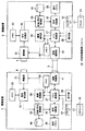
他の技術として、図12に示すように、カメラ101とゲンロック信号発生器103をケーブル104Aで繋ぎ、カメラ102とゲンロック信号発生器103をケーブル104Bで繋ぎ、カメラ101とカメラ102をタイムコード信号用のケーブル105で繋いでいた。そして、ゲンロック信号発生器103で発生したゲンロック信号(Genlock in)をカメラ101,102の各々に入力することにより、2台のカメラを同期させていた。またタイムコード信号の入力及び出力(TC in、TC out)は、ケーブル105を通じて送受信していた。
As another technique, as shown in FIG. 12, the camera 101 and the
また、2台のカメラのカメラ設定値(撮影パラメータ)を合わせるために、一方のカメラの設定値を含む設定ファイルをメモリカードに記憶させた後、他方のカメラで当該メモリカードから設定ファイルを呼び出すことで2台のカメラの設定を合わせていた。あるいは、撮影者がメニューや遠隔操作装置(リモート・コントローラ、所謂リモコン)で2台のカメラの設定値を比較しながら設定を合わせる操作が必要であった。また、2台のカメラでほぼ同時に記録を開始するためには、カメラ本体やリモコンの録画ボタンを2台のカメラで同時に押すなどの操作が必要であった。 In order to match the camera setting values (shooting parameters) of the two cameras, a setting file including the setting values of one camera is stored in the memory card, and then the setting file is called from the memory card by the other camera. The settings of the two cameras were matched. Alternatively, it is necessary for the photographer to adjust the settings while comparing the setting values of the two cameras with a menu or a remote control device (a remote controller, so-called remote controller). Further, in order to start recording almost simultaneously with the two cameras, an operation such as simultaneously pressing the recording buttons of the camera body or the remote controller with the two cameras is required.
これらの不都合を解消するため、特許文献1において以下の技術が提案されている。
特許文献1に開示された技術は、他の撮像装置と通信手段を介して接続し、撮影者が第1の操作スイッチを操作(レリーズボタンの半押し操作)したときに、自装置に設定されている撮影パラメータ値を他の撮像装置に転送することで、自動的に共通の撮影パラメータ値を他の撮像装置にも設定するというものである。さらに、特許文献1には、撮影者が第2の操作スイッチを操作(レリーズボタンの全押し操作)したときに、他の撮像装置に撮影命令を送信し、それぞれの撮像装置間で同一のタイミングで撮影する技術が開示されている。この技術により、自カメラの撮影動作とほぼ同時に、接続先のカメラ撮影動作を自動的に行うことが可能となる。
In order to eliminate these disadvantages,
The technique disclosed in
しかしながら、従来の技術では、2台のカメラを接続するケーブルが多く、撮影機材が大掛かりになってしまう。また、2台のカメラの設定値を合わせるためのメモリカードの抜き差しや、メニュー画面で設定値のStore(記憶)/Recall(読み出し)操作が必要で、さらに実際に設定値が同じかどうかの確認など手間と時間がかかっていた。なお、特許文献1に記載の撮影方法は、レリーズボタンの半押し操作したときに、自装置に設定されている撮影パラメータ値を他の撮像装置に転送するので、撮影の直前に撮影パラメータ値を他装置に設定し、また撮影時に自装置と他装置が常に同じ撮影パラメータ値に設定される。
However, in the conventional technology, there are many cables connecting two cameras, and the photographing equipment becomes large. Also, it is necessary to insert / remove the memory card to match the setting values of the two cameras, and to store / recall the setting values on the menu screen, and check whether the setting values are actually the same. It took time and effort. Note that in the photographing method described in
本開示は、上記の状況を考慮してなされたものであり、立体映像等の動画像の撮影における2台のカメラの撮影準備の省力化を図るものである。 The present disclosure has been made in consideration of the above situation, and is intended to save labor in shooting preparation of two cameras in shooting a moving image such as a stereoscopic video.
本開示の一側面の動画像撮影システムは、第1撮像装置と、第2撮像装置と、第1撮像装置と第2撮像装置を接続し、第1撮像装置で連続的に撮像されるフレームと第2撮像装置で連続的に撮像されるフレームを同期するための同期信号と、タイムコードを合わせるためのタイムコード信号と、撮影パラメータを含むデータ信号と、を少なくとも含む複数種類の信号を伝送する1本のケーブルを備える。 A moving image capturing system according to an aspect of the present disclosure includes a first imaging device, a second imaging device, a frame that connects the first imaging device and the second imaging device, and is continuously imaged by the first imaging device. transmission and synchronization signals for synchronizing the frames are continuously captured by the second imaging device, and the time code signal for adjusting the time code, and a data signal including the shooting parameters, a plurality of types of signals including at least a One cable is provided.
上記動画像撮影システムの一例として、以下の構成をとる。
第1撮像装置及び第2撮像装置の各々は、撮像装置本体の回路と接続し、ケーブルを介して他装置の同期信号が入力される第1入力回路と、撮像装置本体の回路と接続し、ケーブルを介して自装置の同期信号を出力する第1出力回路と、撮像装置本体の回路と接続し、ケーブルを介して他装置のタイムコード信号が入力される第2入力回路と、撮像装置本体の回路と接続し、ケーブルを介して自装置のタイムコード信号を出力する第2出力回路と、を有する。
また、ケーブルの同期信号を伝送する第1導線と接続し、自装置の設定に応じて第1入力回路と第1出力回路を切り替える第1切替部と、ケーブルのタイムコード信号を伝送する第2導線と接続し、自装置の設定に応じて第2入力回路と第2出力回路を切り替える第2切替部とを有する。さらに、操作入力信号に基づいて自装置をメイン又はサブに設定し、該設定に応じて第1切替部と第2切替部に切り替えを指示する制御部とを有する。
The following configuration is taken as an example of the moving image shooting system.
Each of the first imaging device and the second imaging device is connected to a circuit of the imaging device body, and is connected to a first input circuit to which a synchronization signal of another device is input via a cable, and a circuit of the imaging device body, A first output circuit that outputs a synchronization signal of the own device via a cable, a second input circuit that is connected to a circuit of the imaging device main body and receives a time code signal of another device via the cable, and the imaging device main body And a second output circuit that outputs a time code signal of the device itself via a cable.
In addition, the first switching unit is connected to the first conductor for transmitting the synchronization signal of the cable and switches between the first input circuit and the first output circuit according to the setting of the own device, and the second is for transmitting the time code signal of the cable . It has a 2nd switching part which connects with conducting wire and switches a 2nd input circuit and a 2nd output circuit according to the setting of an own apparatus. Furthermore, it has a control unit that sets its own device to main or sub based on the operation input signal and instructs the first switching unit and the second switching unit to switch according to the setting.
上述した本開示の一側面の構成によれば、1本のケーブルで接続された2台の撮像装置のメイン/サブを設定し、その設定に応じて各々の撮像装置に設けた入力回路と出力回路が切り替えられる。ゆえに、2台の撮像装置のメイン/サブの設定がいずれであっても、2台の撮像装置を動画像撮影システムとして機能させることができる。それにより同期信号を伝送する第1導線とタイムコード信号を伝送する第2導線を、1本の専用ケーブル内にそれぞれ一つずつ用意するだけでよい。 According to the configuration of the one aspect of the present disclosure described above, the main / sub of the two imaging devices connected by one cable are set, and the input circuit and output provided in each imaging device according to the setting The circuit is switched. Therefore, regardless of the main / sub setting of the two imaging devices, the two imaging devices can function as a moving image capturing system. Thereby, it is only necessary to prepare one each of the first conductor for transmitting the synchronization signal and the second conductor for transmitting the time code signal in one dedicated cable.
本開示の一側面の同期制御方法では、動画像撮影システムを構成する、1本のケーブルで接続された第1撮像装置と第2撮像装置の各々において、制御部が操作入力信号に基づいて自装置をメイン又はサブに設定する。
次に、制御部が設定に応じて、撮像装置本体の回路と接続し、ケーブルを介して他装置の同期信号が入力される第1入力回路と、撮像装置本体の回路と接続し、ケーブルを介して自装置の同期信号を出力する第1出力回路を切り替えるよう、ケーブルの同期信号を伝送する第1導線と接続する第1切替部に指示する。
また、制御部が設定に応じて、撮像装置本体の回路と接続し、ケーブルを介して他装置のタイムコード信号が入力される第2入力回路と、撮像装置本体の回路と接続し、ケーブルを介して自装置のタイムコード信号を出力する第2出力回路を切り替えるよう、ケーブルのタイムコード信号を伝送する第2導線と接続する第2切替部に指示する。
そして、第1切替部が、制御部からの指示に基づいて第1入力回路と第1出力回路を切り替え、第2切替部が、制御部からの指示に基づいて第2入力回路と第2出力回路を切り替える。
In the synchronization control method according to one aspect of the present disclosure, in each of the first imaging device and the second imaging device that are connected by a single cable that configures the moving image capturing system , the control unit automatically performs control based on an operation input signal. Set the device to main or sub.
Next, according to the setting, the control unit connects to the circuit of the imaging device body, connects the first input circuit to which the synchronization signal of the other device is input via the cable, and the circuit of the imaging device body, and connects the cable. The first switching unit connected to the first conductor that transmits the synchronization signal of the cable is instructed to switch the first output circuit that outputs the synchronization signal of the own device through the first switching circuit.
In addition, the control unit connects to the circuit of the imaging apparatus body according to the setting, connects the second input circuit to which the time code signal of the other apparatus is input via the cable, and the circuit of the imaging apparatus body, and connects the cable. The second switching unit connected to the second conductor that transmits the time code signal of the cable is instructed to switch the second output circuit that outputs the time code signal of the own device through the second switching circuit.
The first switching unit switches between the first input circuit and the first output circuit based on an instruction from the control unit, and the second switching unit switches between the second input circuit and the second output based on an instruction from the control unit. Switch the circuit.
上述した本開示の一側面の方法によれば、1本のケーブルで接続された2台の撮像装置のメイン/サブを設定し、その設定に応じて各々の撮像装置に設けた入力回路と出力回路が切り替えられる。ゆえに、2台の撮像装置のメイン/サブの設定がいずれであっても、2台の撮像装置を動画像撮影システムとして機能させることができる。 According to the method of one aspect of the present disclosure described above, the main / sub of the two imaging devices connected by one cable are set, and the input circuit and output provided in each imaging device according to the setting The circuit is switched. Therefore, regardless of the main / sub setting of the two imaging devices, the two imaging devices can function as a moving image capturing system.
本開示によれば、立体映像の撮影における2台の撮像装置の撮影準備の省力化を図ることができる。 According to the present disclosure, it is possible to save labor in shooting preparation of the two imaging devices in shooting a stereoscopic image.
以下、本開示を実施するための形態の例(以下、「実施形態例」ともいう)について、添付図面を参照しながら説明する。説明は下記の順序で行う。なお、各図において共通の構成要素には、同一の符号を付して重複する説明を省略する。
1.一実施の形態(1本の専用ケーブルで2台の撮像装置を接続する例)
2.その他(メインからサブへのカメラ設定値の反映例、記録開始及び再生停止の例)
Hereinafter, exemplary embodiments for implementing the present disclosure (hereinafter, also referred to as “embodiment examples”) will be described with reference to the accompanying drawings. The description will be given in the following order. In addition, in each figure, the same code | symbol is attached | subjected to the common component and the overlapping description is abbreviate | omitted.
1. One embodiment (example of connecting two imaging devices with one dedicated cable)
2. Others (example of camera settings reflected from main to sub, example of recording start and playback stop)
<1.一実施の形態>
[立体映像撮像システムの外部構成]
本実施の形態では、2台の撮像装置(カメラ)を1本の専用ケーブルで接続して立体映像を撮像する立体映像撮像システム10に適用した例(以下、「本例」という。)について説明する。
<1. Embodiment>
[External configuration of 3D imaging system]
In the present embodiment, an example (hereinafter referred to as “this example”) applied to a stereoscopic video imaging system 10 that captures a stereoscopic video by connecting two imaging devices (cameras) with one dedicated cable. To do.
図1は、本開示の一実施の形態における、立体映像撮像システムの外部構成例を示すブロック図である。
立体映像撮像システム10は、1秒間に同一のフレーム数で同一の画サイズの2次元映像を撮像する撮像装置として、リグ4に設置した第1の撮像装置1及び第2の撮像装置2を備える。被写体からの入射光はハーフミラー5を通して透過光と反射光に分離され、撮像装置1及び撮像装置2のそれぞれの光学系6に入射する。撮像装置1及び撮像装置2は、共通する端子を備え、本願出願人が開発した一本の専用ケーブル3で接続されている。撮像装置1及び撮像装置2は、互いに映像の記録又は再生等の処理をフレーム単位で同期する制御を行うためのゲンロック信号(同期信号)、動画編集等に用いられるタイムコード信号などを送受信できる。
FIG. 1 is a block diagram illustrating an external configuration example of a stereoscopic video imaging system according to an embodiment of the present disclosure.
The stereoscopic image capturing system 10 includes a first
また、撮像装置1及び第2の撮像装置2は、撮影者がそれぞれ操作入力により各部に動作を指示する操作部を備える。図1では、操作部の一例として、アサイナブルボタン7及び録画ボタン8を記載している。撮像装置1及び撮像装置2は、メモリカードを装着するためのスロット9を備える。
In addition, the
[専用ケーブルの構成]
次に、図2〜図4及び表1を参照して、本開示の一実施の形態における、専用ケーブル3の構成について説明する。
図2は、専用ケーブル3の構成を示した概略図である。図3は、撮像装置内の入力回路と出力回路の内部構成例を示した説明図である。図4は、撮像装置内の入力回路と出力回路を示した説明図である。
[Configuration of dedicated cable]
Next, the configuration of the
FIG. 2 is a schematic diagram showing the configuration of the
図2に示すように、専用ケーブル3は、筒状の保護被覆3a(図4参照)内に、ゲンロック信号用の同軸線12とタイムコード信号用の同軸線13、データ信号用の4つの導線14〜17を有している。同軸線12,13の特性インピーダンスは、一例として75Ω又は50Ωとする。専用ケーブル3の両端には、オス型のコネクタ11A,11Bが設けられている。コネクタ11A,11Bは同一の構成であり、それぞれに8個の端子(ピン)を有している。2つのコネクタ11A,11Bの対応する端子間は、これらの信号線により導通している。
As shown in FIG. 2, the
表1に、専用ケーブル3のコネクタ11A,11Bの端子に入出力する信号名称を示す。

表1に示すように、本例では、専用ケーブル3のコネクタ11A,11Bの第1ピンがゲンロック信号の基準電位(Genlock(GND))に、第2ピンがゲンロック信号(Genlock)に、第3ピンがタイムコード信号の基準電位(TC(GND))に、第4ピンがタイムコード信号(TC)に、第5〜8ピンまでがデータ信号に割り当てられている。この例では、第5ピンを受信データ(RX)に、第6ピンを送信データ(TX)に、第7ピンをクロック信号(CLK)に、第8ピンをチップセレクト信号(CS)に割り当てている。
As shown in Table 1, in this example, the first pin of the
受信データ(RX)及び送信データ(TX)に含まれる情報は、撮像装置1又は撮像装置2の記録開始や記録停止などの入力操作信号やそれに基づく制御信号、カメラ設定値(撮影パラメータ)などである。クロック信号(CLK)は、撮像装置1又は撮像装置2内の複数のブロックが動作のタイミングを合わせるのに使用される信号である。チップセレクト信号(CS)は、撮像装置1又は撮像装置2におけるハードウェアモジュール(IC等)のうちいずれを有効にするかを表す信号である。チップセレクト信号がアクティブのとき該当ハードウェアモジュールの読み出しや書き込みが可能となる。
Information included in the reception data (RX) and transmission data (TX) includes input operation signals such as recording start and recording stop of the
専用ケーブル3のコネクタ11A(オス)と撮像装置1のコネクタ21(メス)を接続し、専用ケーブル3のコネクタ11B(オス)と撮像装置2のコネクタ21(メス)を接続することによって、撮像装置1と撮像装置2が物理的及び電気的に接続する。
By connecting the
[入力回路と出力回路の切り替え]
本開示の立体映像撮像システムは、2台の撮像装置1,2を1本の専用ケーブル3で接続し、1本のケーブルでゲンロック信号、タイムコード信号及びデータ信号を伝達し、カメラ設定、同期及び記録開始/停止等を行うことができる。以下、撮像装置において入力回路と出力回路を切り替えるための構成を説明する。
[Switching between input circuit and output circuit]
In the stereoscopic video imaging system of the present disclosure, two
図3,図4に示すように、撮像装置1のコネクタ21(メス)に専用ケーブル3のコネクタ11A(オス)を装着すると、コネクタ11Aの各端子(第1〜8ピン)と、対応する撮像装置1の各端子(第1〜8ピン)が物理的及び電気的に接続される。同様に、専用ケーブル3のコネクタ11B(オス)を撮像装置2のコネクタ21(メス)に装着すると、コネクタ11Bの各端子(第1〜8ピン)と、対応する撮像装置2の各端子(第1〜8ピン)が物理的及び電気的に接続される。
As shown in FIGS. 3 and 4, when the
撮像装置1と撮像装置2を1本の専用ケーブル3で接続しているので、撮像装置1と撮像装置2について入力側(メイン:主)と出力側(サブ:従)を設定する必要がある。図3に示した例では、撮像装置1が入力側、撮像装置2が出力側に設定されている。この2つの撮像装置1,2の設定は、撮影状況や撮影者の意図によって入力側と出力側が逆になることもある。以下、設定を切り替えるための撮像装置内部の構成を説明する。撮像装置1と撮像装置2は同様の構成であるので、ここでは撮像装置1について説明する。
Since the
図3に示すように、専用ケーブル3の同軸線12の芯線(内部導体)がコネクタ21の第2端子(第2ピン)に接続し、その外部導体は第1端子(第1ピン)と接続する。外部導体は基本的に零ボルト電位の基準となるものである。そのため第1端子は、コネクタ21の外部金属部分を通して接続される撮像装置本体の電子回路ないし撮像装置筐体のグラウンド線に接続されている。またコネクタ21の第2端子は、コネクタインタフェース22(以下、「コネクタI/F」とも呼ぶ。)と接続している。なお、本例では、4つの導線14〜17を伝送するデータ信号のためのグラウンド線は、同軸線12,13の外部導体と共通とする。
As shown in FIG. 3, the core wire (inner conductor) of the
コネクタI/F22は、撮像装置本体の図示しない電子回路へ繋がる入力回路23及び出力回路24、さらに切替部25を備えている。コネクタ21の第5端子〜第8端子も撮像装置本体の電子回路に接続している。
The connector I /
入力回路23は、一例として入力端が切替部25と接続され出力端が撮像装置本体の電子回路に接続されたバッファアンプ(増幅回路)と、一端が切替部25とバッファアンプとの間に接続され他端がグラウンド線に接続された抵抗器(終端抵抗器)から構成することができる。終端抵抗器には、インピーダンスマッチングをとるために同軸線のインピーダンスに合わせて、75Ωもしくは50Ωの抵抗値が用いられる。
As an example, the
出力回路24は、一例として入力端が撮像装置本体の電子回路と接続されたバッファアンプ(増幅回路)と、一端がバッファアンプの出力端と接続し他端が切替部25と接続した抵抗器(出力抵抗器)から構成することができる。出力抵抗器には、インピーダンスマッチングをとるために同軸線のインピーダンスに合わせて、75Ωもしくは50Ωの抵抗値が用いられる。
For example, the
切替部25は、メイン制御部37からの指示に従い、入力回路23又は出力回路24との接続を切り替える。それにより、撮像装置を入力側(メイン)と出力側(サブ)で切り替えられる。
The switching
専用ケーブル3の同軸線13の芯線(内部導体)と接続するコネクタ21の第4端子(第4ピン)、及び外部導体と接続する第3端子(第3ピン)についても同様である。コネクタI/F22は、撮像装置本体の電子回路へ繋がる入力回路23及び出力回路24、第4端子と接続する切替部25を備え、切替部25により入力回路23又は出力回路24との接続が切り替えられる。
The same applies to the fourth terminal (fourth pin) of the
なお、本例では、一つの切替部25を用いて入力回路23と出力回路24を切り替える構成としたこれに限られない。例えば、入力回路23と出力回路24でバッファアンプ及び抵抗器を共用するとともに複数の切替部を設け、設定に応じて複数の切替部の接続を切り替えて、バッファアンプの向き及び抵抗器の機能(出力抵抗と終端抵抗)を切り替える構成としてもよい。
In this example, the configuration is not limited to the configuration in which the
[立体映像撮像システムの内部構成]
次に、立体映像撮像システム10の内部構成例について説明する。
図5は、本開示の一実施の形態における、立体映像撮像システム10の内部構成例を示すブロック図である。専用ケーブル3で接続された撮像装置1と撮像装置2は同じ機能ブロックを有するので、ここでは撮像装置1の内部構成例について説明する。以下の説明では、入力側(メイン)に設定された撮像装置を「自機」、出力側(サブ)に設定された撮像装置を「他機」と呼ぶことがある。
[Internal configuration of stereoscopic imaging system]
Next, an example of the internal configuration of the stereoscopic video imaging system 10 will be described.
FIG. 5 is a block diagram illustrating an internal configuration example of the stereoscopic video imaging system 10 according to the embodiment of the present disclosure. Since the
撮像装置1は、イメージセンサと、そのイメージセンサから撮像信号を読み出す回路などからなる撮像部31を備える。撮像部31が備えるイメージセンサで、この撮像装置1に装着された光学系6のレンズを介して入射した像光を、電気的な撮像信号に変換する。撮像部31での撮像タイミングや撮像周期、撮像動作は、撮像制御部39により制御される。撮像制御部39は、メモリ40に記憶されているカメラ設定値(撮影パラメータ)やメイン制御部37(制御部の一例)を介して入力される操作部38からの指示内容に基づいて撮像が行われるよう、撮像部31の制御を行う。操作部38の操作などに基づいたカメラ設定値は、メモリ40に保存される。
The
撮像部31が出力した撮像信号は、信号処理部32に入力される。信号処理部32は、入力された撮像信号に対して各種信号処理を行い、映像信号として記録/再生処理部34へ出力する。信号処理部32にはメモリ33が接続してあり、この信号処理部32で信号処理を行うために映像信号のデータを一時記憶処理する。
The imaging signal output by the
記録/再生処理部34は、信号処理部32から入力された映像信号を出力用の所定のフォーマットのビデオ信号に変換し、記録時には大容量記憶装置44へ出力し、再生時には表示制御部35へ出力する。大容量記憶装置としては、ハードディスクや半導体メモリなどが用いられる。なお、記録/再生処理部34において映像信号のフォーマット変換を行わずに、撮像部31が出力した撮像信号(生データ)を、そのまま出力用のビデオ信号として表示制御部35に出力してもよい。
The recording /
本例では、記録/再生処理部34で生成するクロマバースト信号付きビデオ信号(VBS)のクロマバースト信号を同期の基準信号、すなわちゲンロック信号(Genlock)として利用する。なお、撮像装置1,2がメイン(入力側)に設定されたときに、当該撮像装置内にゲンロック信号(Genlock)を発生する回路(図示略)とタイムコード信号(TC)を発生する回路(図示略)を別途設けるようにしてもよい。
In this example, a chroma burst signal of a video signal with a chroma burst signal (VBS) generated by the recording /
表示制御部35では、供給されたビデオ信号から表示パネル36の表示方式や解像度等に合わせて駆動信号を生成し、表示パネル36へ供給する。ビューファインダである表示パネル36は、供給された駆動信号に基づいて画面に映像を表示する。表示パネル36としては、例えば液晶表示パネル等のFPD(Flat Panel Display)が用いられる。
The
操作部38は、例えば、カメラ本体にある操作スイッチ(アサイナブルボタン7、録画ボタン8等)や不図示のリモートコントローラ、プッシュボタン、トグルスイッチ、タッチパネルディスプレイ等が用いられる。操作部38からの入力操作信号は、図示しないインターフェース部を介してメイン制御部37へ入力される。
As the
メモリカード43は、カメラ設定値のデータや撮影した映像データなどを記録するものである。カメラ設定値のデータが記録されたメモリカード43をメモリカード・インタフェース(メモリカードI/F)42に挿入すると、メイン制御部37がそのカメラ設定値のデータをメモリ40に保存する。
The
通信制御部41は、自機(撮像装置1)と他機(撮像装置2)の通信の制御を行う。すなわち、自機のメイン制御部37から出力されたゲンロック信号やタイムコード信号、データ信号を他機へ送信し、逆に他機からゲンロック信号やタイムコード信号、データ信号を受信し、メイン制御部37へ入力する。以下の説明では、撮像装置1と撮像装置2との間で通信する際に、各撮像装置の通信制御部41の記載を省略することがある。
The
また撮像装置1,2は、商用電源又はバッテリから受電する図示しない電源部を備え、各ブロックへ電力を供給している。各ブロックへの電力の供給及び停止は、一例として操作部38の電源ボタン(図示略)を押下して行う。
The
[メイン制御部の内部構成例]
次に、メイン制御部37の内部構成例について説明する。
図6は、本開示の一実施の形態における、メイン制御部37の内部構成例を示すブロック図である。メイン制御部37は、コマンド解析部51、専用ケーブル検出部52、ネゴシエーション部53、入出力切替制御部54、同期制御部55を備えている。メイン制御部37には、MPU(Micro-Processing Unit)などの演算制御装置を用いることができる。
[Internal configuration example of main control unit]
Next, an example of the internal configuration of the
FIG. 6 is a block diagram illustrating an internal configuration example of the
コマンド解析部51は、操作部38からの操作入力信号に含まれるコマンドを解析し、解析した結果を各ブロックに通知する。また、解析の結果に基づいてメモリ40からカメラ設定値(撮影パラメータ)等のデータを読み出して撮像制御部39に制御信号を出力したり、メモリ40にデータを保存したりする。また、通信制御部41との間でデータの送受信を行う。
The
専用ケーブル検出部52は、専用ケーブル3のコネクタ11Aが撮像装置1のコネクタ21に挿入された否かを検出し、その結果をネゴシエーション部53に通知する。一例として、専用ケーブル3のコネクタ11Aの所定の端子間に抵抗器を接続しておき、専用ケーブル3を撮像装置1に接続した際、専用ケーブル検出部52が当該抵抗器に応じた電流又は電圧の信号を検出したかどうかで接続の有無を確認することができる。あるいは、メインの撮像装置からサブの撮像装置へ予め決めておいた信号を送信し、これを受信できたかどうかで判断するようにしてもよい。
The dedicated
ネゴシエーション部53は、自機(撮像装置1)と他機(撮像装置2)との間でネゴシエーション処理、すなわち通信を開始するに先立って双方の撮像装置の設定に関する情報の交換を行う。この設定に関する情報には、各撮像装置の通信設定情報に加えて各撮像装置のメインもしくはサブの設定情報も含まれる。ネゴシエーション部53は、コマンド解析部51から立体映像撮像モードが選択されたという通知を受信し、かつ専用ケーブル検出部52から撮像装置1に専用ケーブル3が接続されたという通知を受信したときにネゴシエーション処理を実行する。ネゴシエーション処理により受信した他機の設定に関する情報は、メモリ40に記憶される。
The
入出力切替制御部54は、ネゴシエーション部53からネゴシエーション終了の通知を受信した後、コネクタI/F22(図3,図4参照)の入力回路23と出力回路24の切り替えを行うべく制御する。入出力切替制御部54は、自機の入力回路23と出力回路24の切り替えを指示するとともに、他機に対しても入力回路23と出力回路24の切り替えを指示する。
The input / output
同期制御部55は、入出力切替制御部54から入力回路23と出力回路24の切り替え終了の通知を受信した後、自機と他機の同期をとるべく制御を行う。本例では、同期制御部55は、通信制御部41を通じて他機とゲンロック信号及びタイムコード信号の送受信を行い、ゲンロックとタイムコードを同期する。
The
表示制御部35は、コマンド解析部51から入力される操作入力信号の解析結果や同期制御部55からの入力に応じて駆動信号を生成し、表示パネル36へ供給する。
The
以上が撮像装置1の内部構成であるが、撮像装置2についても同様な構成である。
The above is the internal configuration of the
[撮影準備完了までの処理例]
次に、図7のフローチャートを参照して、専用ケーブル3で接続された2台の撮像装置1,2による撮影準備完了までの処理例を説明する。
[Example of processing until shooting preparation is completed]
Next, with reference to the flowchart of FIG. 7, an example of processing up to the completion of shooting preparation by the two
まず撮影者は、撮像装置1の電源ボタンを押下して、撮像装置1の電源をオンにする。この時点では、撮像装置1と撮像装置2のいずれがメイン(入力側)であり、サブ(出力側)であるか決まっていない。以下では、撮像装置1をメインの撮像装置に設定し、撮像装置2をサブの撮像装置に設定するという想定で説明を行う。
First, the photographer presses the power button of the
次に、撮影者は、撮像装置1のメニューから立体映像撮像モードを選択する(ステップS1)。そして、撮影者は、一例として撮像装置1をメイン(入力側)の撮像装置に設定する。撮像装置1のメイン制御部37のコマンド解析部51は、操作部38からの入力操作信号を解析して撮像装置1がメインの撮像装置に設定されたと判断し、その設定内容をメモリ40に保存する。
Next, the photographer selects a stereoscopic video imaging mode from the menu of the imaging device 1 (step S1). Then, the photographer sets the
設定の際は、撮影者が操作部38を操作して一例として図8に示すようなメニュー画面を表示パネル36に表示して設定を行う。撮影者はまずメインメニューを画面に表示させ、撮影を行うメニュー項目である“カメラ”を選択して、メインメニューの右側にカメラメニューを表示させる。そのカメラメニューの中から立体映像撮像モードである“3D-Link Mode”を選択し、カメラメニューの右側に3D-Link Modeメニューを表示させる。撮影者は、複数のメニュー項目から“メイン”を選択することにより、撮像装置1をメイン(入力側)の撮像装置に設定する。
In setting, the photographer operates the
同様にして、撮影者は、撮像装置2の電源をオンにし、撮像装置2のメニューから立体映像撮像モードを選択する(ステップS2)とともに、撮像装置2をサブ(出力側)の撮像装置に設定する。
Similarly, the photographer turns on the power of the
なお、2つの撮像装置1,2に対するメイン又はサブの設定を予め実行してメモリ40に保存しておき、撮像装置1,2の電源がオンしたとき、各撮像装置がメモリ40からその設定をメモリ40から呼び出す構成としてもよい。
Note that main or sub settings for the two
次に、撮影者が、撮像装置1のコネクタ21に専用ケーブル3のコネクタ11Aを接続し、撮像装置2のコネクタ21に専用ケーブル3のコネクタ11Bを接続する。
撮像装置1では、メイン制御部37(専用ケーブル検出部52)が、専用ケーブル3のコネクタ11Aが撮像装置1のコネクタ21に挿入されたことを検出する(ステップS3)。同様に、撮像装置2でも、メイン制御部37(専用ケーブル検出部52)が、専用ケーブル3のコネクタ11Bが撮像装置2のコネクタ21に挿入されたことを検出する(ステップS4)。なお、ステップS1,S2の立体映像撮像モードの選択処理と、ステップS3,S4の専用ケーブル3の接続処理は、順序が逆でもよい。
Next, the photographer connects the connector 11 </ b > A of the
In the
撮像装置1及び撮像装置2に専用ケーブル3が接続されたら、撮像装置1と撮像装置2との間でネゴシエーション処理を行う。
撮像装置1内のメイン制御部37(ネゴシエーション部53)は、撮像装置2に対して撮像装置の設定に関する情報を送信するよう要求する(ステップS5)。撮像装置2のメイン制御部37(ネゴシエーション部53)は、要求を受けて当該撮像装置2の設定に関する情報を撮像装置1へ返信する(ステップS6)。撮像装置1のメイン制御部37(ネゴシエーション部53)はこれを受信し、撮像装置2の設定に関する情報をメモリ40に保存する(ステップS7)。
When the
The main control unit 37 (negotiation unit 53) in the
ネゴシエーション処理が終了後、撮像装置1のメイン制御部37(入出力切替制御部54)は、コネクタI/F22の切替部25(第1切替部)を出力回路24側へ切り替える(ステップS8)。これにより、バッファアンプの向きと抵抗器(出力抵抗器)が切り替えられ、ゲンロック用とタイムコード用の回路が出力側へ切り替えられる。切り替え後、撮像装置1のメイン制御部37(入出力切替制御部54)は、撮像装置2に対しゲンロック用とタイムコード用の回路を入力側へ切り替えを指示するコマンドを送信する(ステップS9)。
After the negotiation process is completed, the main control unit 37 (input / output switching control unit 54) of the
撮像装置2のメイン制御部37(入出力切替制御部54)は、撮像装置1からゲンロック用とタイムコード用の回路を入力側へ切り替えを指示するコマンドを受信する(ステップS10)。撮像装置2のメイン制御部37(入出力切替制御部54)は、コマンドを受信すると、コネクタI/F22の切替部25(第2切替部)を出力回路24側へ切り替える(ステップS11)。これにより、バッファアンプの向きと抵抗器(終端抵抗器)が切り替えられ、ゲンロック用とタイムコード用の回路が入力側へ切り替えられる。切り替え後、撮像装置2のメイン制御部37(入出力切替制御部54)は、撮像装置1に対しゲンロック用とタイムコード用の回路の入力側への切り替えが完了したことを示すコマンドを送信する(ステップS12)。
The main control unit 37 (input / output switching control unit 54) of the
撮像装置1のメイン制御部37(入出力切替制御部54)は、撮像装置2からゲンロック用とタイムコード用の回路の入力側への切り替えが完了したことを示すコマンドを受信する(ステップS13)。
The main control unit 37 (input / output switching control unit 54) of the
上記ステップS1〜S13の処理では、撮像装置1と撮像装置2との間の通信は、専用ケーブル3の導線14(受信信号(RX)用)と導線15(送信信号(TX)用)を利用して行われる。
In the processing in steps S1 to S13, the communication between the
次に、撮像装置1のメイン制御部37(同期制御部55)は、専用ケーブル3の同軸線12を通じてゲンロック信号を撮像装置2へ送信する。また、撮像装置1のメイン制御部37(同期制御部55)は、専用ケーブル3の同軸線13を通じてタイムコード信号を撮像装置2へ送信する(ステップS14)。
Next, the main control unit 37 (synchronization control unit 55) of the
撮像装置2のメイン制御部37(同期制御部55)は、専用ケーブル3を介して撮像装置1からゲンロック信号とタイムコード信号を受信し同期する(ステップS15)。そして、撮像装置2のメイン制御部37(同期制御部55)は、撮像装置1からゲンロック信号とタイムコード信号を受信して同期が完了すると、同期が完了したことを示すコマンドを、専用ケーブル3の導線15を通じて撮像装置1へ送信する(ステップS16)。
The main control unit 37 (synchronization control unit 55) of the
撮像装置1のメイン制御部37(同期制御部55)は、撮像装置2からゲンロック信号とタイムコード信号の同期が完了したことを示すコマンドを、専用ケーブル3の導線15を通じて受信する(ステップS17)。
The main control unit 37 (synchronization control unit 55) of the
撮像装置1のメイン制御部37は、表示制御部35に対し、撮像装置1がメイン(出力側)に設定されていることを示す画面を表示するよう指示する(ステップS18)。この指示を受けて、表示制御部35が表示パネル36に駆動信号を出力し、ビューファインダに撮像装置1がメインであることを示す画面61(図9参照)が表示される。また、立体映像として記録されるように撮影したとき、当該撮像装置1が左右のどちらになるかという状態も、同じくビューファインダ上に表示される。この例では、撮像装置1が左眼に対応するよう設定されているので、“3D-Main”とともに“Left”と表示されている。
The
撮像装置1の表示と並行して、撮像装置2のメイン制御部37は、表示制御部35に対し、撮像装置2がサブ(入力側)に設定されていることを示す画面を表示するよう指示する(ステップS19)。この指示を受けて、表示制御部35が表示パネル36に駆動信号を出力し、ビューファインダに撮像装置2がサブであることを示す画面62(図10参照)が表示される。この例では、撮像装置2が右眼に対応するよう設定されているので、“3D-Sub”とともに“Right”と表示されている。
In parallel with the display of the
上述した各処理を経て、撮像装置1と撮像装置2が立体映像を撮像できる状態に遷移する。
After each process described above, the
以上説明したように、本開示の一実施の形態によれば、2台の撮像装置を専用ケーブルで接続し、2台の撮像装置でメイン/サブを設定した場合に各々の撮像装置の入出力I/Fに設けた入力回路と出力回路が切り替えられる構成を有する。ゆえに、2台の撮像装置のメイン/サブの設定がいずれであっても、2台の撮像装置を立体映像撮像システムとして機能させることができる。
この構成を有することにより、ゲンロック信号を伝送する導線(一例として同軸線)とタイムコード信号を伝送する導線(一例として同軸線)を、1本の専用ケーブル内にそれぞれ一つずつ用意するだけでよい。すなわち、2台の撮像装置に1本のケーブルをつなぐことで2台の撮像装置の同期とタイムコードを合わせることができる。
それゆえ、2台の撮像装置の同期、タイムコードを合わせるための複数の導線を1本のケーブルに集約し、ケーブルの数を減らすことができる。よって、立体映像撮像システムの2台の撮像装置に複数のケーブルを接続する必要がなくので、撮影準備の省力化が図られる。
As described above, according to an embodiment of the present disclosure, when two imaging devices are connected by a dedicated cable and main / sub are set by the two imaging devices, input / output of each imaging device The input / output circuit provided in the I / F can be switched. Therefore, regardless of the main / sub setting of the two imaging devices, the two imaging devices can function as a stereoscopic video imaging system.
By having this configuration, it is only necessary to prepare one lead wire for transmitting a genlock signal (coaxial wire as an example) and one lead wire for transmitting time code signals (coaxial wire as an example) in one dedicated cable. Good. That is, the synchronization and time code of the two imaging devices can be matched by connecting one cable to the two imaging devices.
Therefore, a plurality of conductors for synchronizing the two imaging devices and adjusting the time code can be integrated into one cable, and the number of cables can be reduced. Therefore, it is not necessary to connect a plurality of cables to the two imaging devices of the stereoscopic video imaging system, so that labor saving in shooting preparation can be achieved.
<2.その他>
[メインの撮像装置からサブの撮像装置へのカメラ設定値の反映例]
2台の撮像装置1,2でゲンロック信号とタイムコード信号の同期が完了後、メインに設定された撮像装置1のアサイナブルボタン7(メイン撮像装置の設定データを送信する機能を割り当て済み)を押下すると、撮像装置1のカメラ設定値(撮影パラメータ)がサブである撮像装置2に送信され、メモリ40に保存される。これにより、撮像装置1のカメラ設定値が撮像装置2に反映される。このときに送信されるカメラ設定の項目として、例えばシャッタータイミング、ガンマ補正、ホワイトバランス、ゲイン、マトリクスなどが挙げられる。カメラ設定値を反映中の状態は、一例として図11に示すような画面61Aとしてビューファインダに表示される。
<2. Other>
[Example of reflection of camera setting values from main imaging device to sub imaging device]
After the synchronization between the genlock signal and the time code signal is completed in the two
立体映像撮影のために2台の撮像装置の設定を合わせるための操作にかかる時間を大きく削減することができるので、撮影準備の省力化が図られる。 Since it is possible to greatly reduce the time required for the operation for matching the settings of the two imaging devices for stereoscopic video shooting, it is possible to save labor for shooting preparation.
なお、本例では、撮影者がアサイナブルボタンを押下してメイン側からサブ側へカメラ設定値を送信するとしたが専用ボタンでもよいし、メニューから撮像装置1の設定データを送信する項目を選択して上記送信機能を実行してもよい。あるいは、2台の撮像装置1,2でゲンロック信号とタイムコード信号の同期が完了した後、メイン側からサブ側へカメラ設定値を自動的に送信してカメラ設定値を共有する構成としてもよい。
In this example, the photographer presses the assignable button and transmits the camera setting value from the main side to the sub side. However, a dedicated button may be used, and an item for transmitting the setting data of the
本例では、メインの撮像装置1のカメラ設定値をサブの撮像装置2へ反映する処理は、撮影者が上述したような設定データを送信する操作を実行したときのみを想定している。すなわち、メインの撮像装置1のカメラ設定値をサブの撮像装置2へ反映した後、ずっとメイン側とサブ側のカメラ設定値が連動(同期)するわけではなく、各撮影パラメータの設定値を撮像装置ごとに変えることができる。これは、例えば、光学系のレンズのガラスの色など、撮像装置によって若干の固体差があり、2台の撮像装置で少しだけ設定値を変えたい項目が存在するためである。このように、2台の撮像装置のカメラ設定値をまったく同じにするだけでなく、オフセットをつけることも可能であり、実際に使用する2台の撮像装置に合わせた撮影が行える。
In this example, the process of reflecting the camera setting value of the
[記録開始及び再生停止の例]
撮影者が、メインの撮像装置1の録画ボタン又はリモコンの録画ボタンを押して撮像装置1に録画を指示すると、撮像装置1のメイン制御部37はサブの撮像装置2へ録画コマンドを送信する。撮像装置1と撮像装置2は既に同期がとれているので、撮像装置1が撮像装置2へ記録開始フレーム情報を指示することにより撮像装置1と撮像装置2で同時に記録(撮影)を開始することができる。同様に、メインの撮像装置1の操作部38の停止ボタン又はリモコンの停止ボタンを押して、撮像装置1と撮像装置2で同時に記録を停止できる。また撮像装置1又は撮像装置2の記録メディア(例えばメモリカード43)の空き容量が無くなった場合や記録メディアに異常が発生した場合なども、撮像装置1と撮像装置2で同時に記録を停止できる。
[Example of recording start and playback stop]
When the photographer presses the recording button of the
このように、本開示によれば、2台の撮像装置の記録開始と記録停止を1回の操作で確実に実行できる。 As described above, according to the present disclosure, the recording start and the recording stop of the two imaging devices can be reliably executed by one operation.
上述した実施の形態においては、撮像装置1をメインに設定し、撮像装置2をサブに設定したが、メインとサブを逆に設定してもよいことは勿論である。
In the embodiment described above, the
また、上述した実施の形態では、ゲンロック信号及びタイムコード信号の伝送用に同軸線を用いる構成としたが(図3〜図5参照)、データ信号伝送用の導線と同じ構成としてもよい。 In the above-described embodiment, the coaxial line is used for transmission of the genlock signal and the time code signal (see FIGS. 3 to 5). However, the same configuration as that of the data signal transmission line may be used.
なお、本技術は以下のような構成もとることができる。
(1)
第1撮像装置と、
第2撮像装置と、
第1撮像装置と第2撮像装置を接続し、第1撮像装置と第2撮像装置の間で同期するための同期信号と、タイムコードを合わせるためのタイムコード信号と、及び少なくとも撮影パラメータを含むデータ信号と、を伝送する1本のケーブルを備える
立体映像撮像システム。
(2)
第1撮像装置及び第2撮像装置の各々は、
撮像装置本体の回路と接続し、前記ケーブルを介して他装置の同期信号が入力される第1入力回路と、
撮像装置本体の回路と接続し、前記ケーブルを介して自装置の同期信号を出力する第1出力回路と、
撮像装置本体の回路と接続し、前記ケーブルを介して他装置のタイムコード信号が入力される第2入力回路と、
撮像装置本体の回路と接続し、前記ケーブルを介して自装置のタイムコード信号を出力する第2出力回路と、
前記同期信号を伝送する第1導線と接続し、自装置の設定に応じて第1入力回路と第1出力回路を切り替える第1切替部と、
前記タイムコード信号を伝送する第2導線と接続し、自装置の設定に応じて第2入力回路と第2出力回路を切り替える第2切替部と、
操作入力信号に基づいて自装置をメイン又はサブに設定し、該設定に応じて第1切替部と第2切替部に切り替えを指示する制御部と、を有する
前記(1)に記載の立体映像撮像システム。
(3)
前記制御部は、自装置をメインに設定したときは第1切替部と第2切替部に対し、第1出力回路と第2出力回路に切り替えるよう指示し、自装置をサブに設定したときは第1切替部と第2切替部に対し、第1入力回路及び第2入力回路に切り替えるよう指示する
前記(2)に記載の立体映像撮像システム。
(4)
前記制御部は、第1切替部と第2切替部による切り替えが完了した後、前記同期信号を前記ケーブルの第1導線を通じて他装置へ送信し、前記タイムコード信号を前記ケーブルの第2導線を通じて他装置へ送信する
前記(3)に記載の立体映像撮像システム。
(5)
前記制御部は、自装置がメインに設定された場合に、前記同期信号と前記タイムコード信号を他装置へ送信した後、撮影パラメータの送信を指示する操作入力信号を受信して自装置の撮影パラメータを他装置へ送信する
前記(4)に記載の立体映像撮像システム。
(6)
前記制御部は、自装置がメイン又はサブのいずれかに設定されたこと、及び前記ケーブルが第1撮像装置と第2撮像装置に接続されたことを検出した場合に、第1切替部と第2切替部に切り替えを指示する
前記(3)乃至(5)のいずれかに記載の立体映像撮像システム。
(7)
前記ケーブルの前記第1導線と前記第2導線は、同軸線の芯線である
前記(2)乃至(6)のいずれかに記載の立体映像撮像システム。
(8)
立体映像撮像システムを構成する、1本のケーブルで接続された第1撮像装置と第2撮像装置の各々が、制御部が操作入力信号に基づいて自装置をメイン又はサブに設定すること、
前記制御部が前記設定に応じて、撮像装置本体の回路と接続し、前記ケーブルを介して他装置の同期信号が入力される第1入力回路と、撮像装置本体の回路と接続し、前記ケーブルを介して自装置の同期信号を出力する第1出力回路を切り替えるよう、前記同期信号を伝送する第1導線と接続する第1切替部に指示すること、
前記制御部が前記設定に応じて、撮像装置本体の回路と接続し、前記ケーブルを介して他装置のタイムコード信号が入力される第2入力回路と、撮像装置本体の回路と接続し、前記ケーブルを介して自装置のタイムコード信号を出力する第2出力回路を切り替えるよう、前記タイムコード信号を伝送する第2導線と接続する第2切替部に指示すること、
第1切替部が、前記制御部からの指示に基づいて第1入力回路と第1出力回路を切り替えること、
第2切替部が、前記制御部からの指示に基づいて第2入力回路と第2出力回路を切り替えること、
を含む同期制御方法。
In addition, this technique can also take the following structures.
(1)
A first imaging device;
A second imaging device;
The first imaging device is connected to the second imaging device, and includes a synchronization signal for synchronizing between the first imaging device and the second imaging device, a time code signal for matching the time code, and at least an imaging parameter. A stereoscopic video imaging system comprising a single cable for transmitting data signals.
(2)
Each of the first imaging device and the second imaging device is
A first input circuit that is connected to a circuit of the imaging apparatus main body and receives a synchronization signal of another apparatus via the cable;
A first output circuit connected to a circuit of the imaging apparatus main body and outputting a synchronization signal of the own apparatus via the cable;
A second input circuit that is connected to a circuit of the imaging apparatus main body and receives a time code signal of another apparatus via the cable;
A second output circuit that is connected to a circuit of the imaging apparatus body and outputs a time code signal of the own apparatus via the cable;
A first switching unit that is connected to the first conductor for transmitting the synchronization signal and switches between the first input circuit and the first output circuit according to the setting of the device;
A second switching unit connected to the second conductor for transmitting the time code signal, and switching between the second input circuit and the second output circuit according to the setting of the own device;
The stereoscopic image according to (1), further comprising: a control unit configured to set the own apparatus as main or sub based on the operation input signal and instructing the first switching unit and the second switching unit to switch according to the setting. Imaging system.
(3)
The control unit instructs the first switching unit and the second switching unit to switch to the first output circuit and the second output circuit when the own device is set to main, and when the own device is set to sub The stereoscopic video imaging system according to (2), wherein the first switching unit and the second switching unit are instructed to switch to the first input circuit and the second input circuit.
(4)
After the switching by the first switching unit and the second switching unit is completed, the control unit transmits the synchronization signal to another device through the first conductor of the cable, and transmits the time code signal through the second conductor of the cable. The stereoscopic image capturing system according to (3), which is transmitted to another device.
(5)
When the own device is set to main, the control unit receives the operation input signal instructing transmission of the photographing parameter after transmitting the synchronization signal and the time code signal to the other device, and shoots the own device. The stereoscopic image capturing system according to (4), wherein the parameter is transmitted to another device.
(6)
When the control unit detects that the own device is set to either main or sub and that the cable is connected to the first imaging device and the second imaging device, the control unit and the
(7)
The stereoscopic video imaging system according to any one of (2) to (6), wherein the first conductive wire and the second conductive wire of the cable are core wires of a coaxial line.
(8)
Each of the first imaging device and the second imaging device connected with one cable constituting the stereoscopic video imaging system has its control unit set itself as main or sub based on the operation input signal,
The control unit is connected to a circuit of the imaging apparatus main body according to the setting, and is connected to a circuit of the imaging apparatus main body, a first input circuit to which a synchronization signal of another apparatus is input via the cable, and the cable Instructing the first switching unit connected to the first conductor for transmitting the synchronization signal to switch the first output circuit that outputs the synchronization signal of the own device via
In accordance with the setting, the control unit is connected to a circuit of the imaging device main body, is connected to a second input circuit to which a time code signal of another device is input via the cable, and is connected to a circuit of the imaging device main body, Instructing the second switching unit connected to the second conductor for transmitting the time code signal to switch the second output circuit that outputs the time code signal of the own device via the cable;
The first switching unit switches between the first input circuit and the first output circuit based on an instruction from the control unit;
A second switching unit switching between the second input circuit and the second output circuit based on an instruction from the control unit;
Including a synchronous control method.
なお、上述した一実施の形態例における一連の処理は、ハードウェアにより実行することができるが、ソフトウェアにより実行させることもできる。一連の処理をソフトウェアにより実行させる場合には、そのソフトウェアを構成するプログラムが専用のハードウェアに組み込まれているコンピュータ(またはCPU等の制御装置)、または、各種の機能を実行するためのプログラムをインストールしたコンピュータにより、実行可能である。例えば汎用のパーソナルコンピュータなどに所望のソフトウェアを構成するプログラムをインストールして実行させればよい。 The series of processes in the above-described embodiment can be executed by hardware, but can also be executed by software. When a series of processing is executed by software, a computer (or a control device such as a CPU) in which a program constituting the software is incorporated in dedicated hardware, or a program for executing various functions It can be executed by the installed computer. For example, what is necessary is just to install and run the program which comprises desired software in a general purpose personal computer.
また、上述した実施の形態の機能を実現するソフトウェアのプログラムコードを記録した記録媒体を、システムあるいは装置に供給してもよい。また、そのシステムあるいは装置のコンピュータが記録媒体に格納されたプログラムコードを読み出し実行することによっても、機能が実現されることは言うまでもない。 Further, a recording medium on which a program code of software that realizes the functions of the above-described embodiments may be supplied to the system or apparatus. It goes without saying that the function is also realized by the computer of the system or apparatus reading and executing the program code stored in the recording medium.
この場合のプログラムコードを供給するための記録媒体としては、例えば、フレキシブルディスク、ハードディスク、光ディスク、光磁気ディスク、CD−ROM、CD−R、磁気テープ、不揮発性のメモリカード、ROMなどを用いることができる。 As a recording medium for supplying the program code in this case, for example, a flexible disk, a hard disk, an optical disk, a magneto-optical disk, a CD-ROM, a CD-R, a magnetic tape, a nonvolatile memory card, a ROM, or the like is used. Can do.
また、コンピュータが読み出したプログラムコードを実行することにより、上述した実施の形態の機能が実現される。加えて、そのプログラムコードの指示に基づき、コンピュータ上で稼動しているOSなどが実際の処理の一部又は全部を行う。その処理によって上述した実施の形態の機能が実現される場合も含まれる。 Further, the functions of the above-described embodiment are realized by executing the program code read by the computer. In addition, based on the instruction of the program code, the OS running on the computer performs part or all of the actual processing. The case where the functions of the above-described embodiment are realized by the processing is also included.
また、本明細書において、時系列的な処理を記述する処理ステップは、記載された順序に沿って時系列的に行われる処理はもちろん、必ずしも時系列的に処理されなくとも、並列的あるいは個別に実行される処理(例えば、並列処理あるいはオブジェクトによる処理)をも含むものである。 Further, in this specification, the processing steps describing time-series processing are not limited to processing performed in time series according to the described order, but are not necessarily performed in time series, either in parallel or individually. The processing (for example, parallel processing or object processing) is also included.
以上、本開示は上述した各実施の形態に限定されるものではなく、特許請求の範囲に記載された要旨を逸脱しない限りにおいて、その他種々の変形例、応用例を取り得ることは勿論である。 As described above, the present disclosure is not limited to each of the above-described embodiments, and various other modifications and application examples can be taken without departing from the gist described in the claims. .
1,2…撮像装置、3…専用ケーブル、7…アサイナブルボタン、8…録画ボタン、10…立体映像撮影システム、11A,11B…コネクタ(オス)、12,13…同軸線、14〜17…導線、21…コネクタ(メス)、22…入出力I/F、23…入力回路、24…出力回路、25…切替部、31…撮像部、32…信号処理部、33…メモリ、34…記録/再生処理部、35…表示制御部、36…表示パネル(ビューファインダ)、37…メイン制御部、38…操作部、39…撮像制御部、40…メモリ、41…通信制御部、51…コマンド解析部、52…専用ケーブル検出部、53…ネゴシエーション部、54…入出力切替制御部、55…同期制御部
DESCRIPTION OF
Claims (9)
第2撮像装置と、
前記第1撮像装置と前記第2撮像装置を接続し、前記第1撮像装置で連続的に撮像されるフレームと前記第2撮像装置で連続的に撮像されるフレームを同期するための同期信号と、タイムコードを合わせるためのタイムコード信号と、撮影パラメータを含むデータ信号と、を少なくとも含む複数種類の信号を伝送する1本のケーブルと、を備え、
前記第1撮像装置及び前記第2撮像装置の各々は、
撮像装置本体の回路と接続し、前記ケーブルを介して他装置の同期信号が入力される第1入力回路と、
前記撮像装置本体の回路と接続し、前記ケーブルを介して自装置の同期信号を出力する第1出力回路と、
前記撮像装置本体の回路と接続し、前記ケーブルを介して他装置のタイムコード信号が入力される第2入力回路と、
前記撮像装置本体の回路と接続し、前記ケーブルを介して自装置のタイムコード信号を出力する第2出力回路と、
前記ケーブルの前記同期信号を伝送する第1導線の端部と接続し、自装置の設定に応じて前記第1導線の接続先として前記第1入力回路と前記第1出力回路を切り替える第1切替部と、
前記ケーブルの前記タイムコード信号を伝送する第2導線の端部と接続し、自装置の設定に応じて前記第2導線の接続先として前記第2入力回路と前記第2出力回路を切り替える第2切替部と、
操作入力信号に基づいて自装置をメイン又はサブに設定し、自装置に前記ケーブルが接続されたことを検出すると、該設定に応じて前記第1切替部と前記第2切替部に対し切り替えを指示する制御部と、を有する
動画像撮影システム。 A first imaging device;
A second imaging device;
A synchronization signal for connecting the first imaging device and the second imaging device, and synchronizing a frame continuously imaged by the first imaging device and a frame continuously imaged by the second imaging device; includes a time code signal for adjusting the time code, a one and a cable for transmitting a plurality of types of signals and data signals, the comprising at least including an imaging parameter,
Each of the first imaging device and the second imaging device is
A first input circuit that is connected to a circuit of the imaging apparatus main body and receives a synchronization signal of another apparatus via the cable;
A first output circuit connected to the circuit of the imaging apparatus body and outputting a synchronization signal of the own apparatus via the cable;
A second input circuit that is connected to the circuit of the imaging device main body and receives a time code signal of another device via the cable;
A second output circuit connected to the circuit of the imaging device body and outputting a time code signal of the own device via the cable;
A first switch that connects to the end of the first conductor that transmits the synchronization signal of the cable and switches the first input circuit and the first output circuit as a connection destination of the first conductor according to the setting of the device. And
A second conductor connected to the end of the second conductor for transmitting the time code signal of the cable, and switching the second input circuit and the second output circuit as a connection destination of the second conductor according to the setting of the own device; A switching unit;
Based on the operation input signal, the own device is set to main or sub, and when it is detected that the cable is connected to the own device, the first switching unit and the second switching unit are switched according to the setting. A moving image photographing system having a control unit for instructing
請求項1に記載の動画像撮影システム。 The control unit instructs the first switching unit and the second switching unit to switch to the first output circuit and the second output circuit when the own device is set to main, and sets the own device as a sub. The moving image shooting system according to claim 1 , wherein when set, the first switching unit and the second switching unit are instructed to switch to the first input circuit and the second input circuit.
請求項2に記載の動画像撮影システム。The moving image shooting system according to claim 2.
請求項2に記載の動画像撮影システム。 The control unit, after the switching by the first switching unit and the second switching unit is completed, transmits the synchronization signal from the own device set to the main through the first conductor of the cable to the other device, The moving image capturing system according to claim 2 , wherein the time code signal is transmitted from the main apparatus set as the main to the other apparatus through the second conductor of the cable.
請求項4に記載の動画像撮影システム。 The control unit receives the operation input signal instructing transmission of the imaging parameter after transmitting the synchronization signal and the time code signal to another device when the own device is set to main. The moving image shooting system according to claim 4, wherein the shooting parameters are transmitted to another device.
前記第1撮像装置と前記第2撮像装置との間で前記同期信号と前記タイムコード信号を送受信して同期が完了した後、前記第1撮像装置及び前記第2撮像装置の前記制御部は、自装置をメインに設定した場合には自装置がメインであることを示す画面を自装置の前記表示パネルに表示し、また自装置をサブに設定した場合には自装置がサブであることを示す画面を前記表示パネルに表示するAfter the synchronization is completed by transmitting and receiving the synchronization signal and the time code signal between the first imaging device and the second imaging device, the control unit of the first imaging device and the second imaging device, When the own device is set to main, a screen indicating that the own device is main is displayed on the display panel of the own device, and when the own device is set to sub, the own device is sub. Display the display screen on the display panel
請求項4に記載の動画像撮影システム。The moving image shooting system according to claim 4.
請求項1乃至6のいずれかに記載の動画像撮影システム。 It said first conductor and said second conductor is a moving image photographing system according to any one of claims 1 to 6 is a core wire of a coaxial line of the cable.
請求項1乃至7のいずれかに記載の動画像撮影システム。 The moving image shooting system according to claim 1, wherein a stereoscopic image is generated by frames continuously captured by the first imaging device and the second imaging device.
前記制御部が、自装置に前記ケーブルが接続されたことを検出すること、
前記制御部が、自装置をメイン又はサブに設定し、自装置に前記ケーブルが接続されたことを検出すると、前記設定に応じて、撮像装置本体の回路と接続する、前記ケーブルを介して他装置の同期信号が入力される第1入力回路と、前記撮像装置本体の回路と接続し、前記ケーブルを介して自装置の同期信号を出力する第1出力回路を切り替えるよう、前記ケーブルの前記同期信号を伝送する第1導線の端部と接続する第1切替部に指示すること、
前記制御部が前記設定に応じて、前記撮像装置本体の回路と接続する、前記ケーブルを介して他装置のタイムコード信号が入力される第2入力回路と、前記撮像装置本体の回路と接続し、前記ケーブルを介して自装置の前記タイムコード信号を出力する第2出力回路を切り替えるよう、前記ケーブルの前記タイムコード信号を伝送する第2導線の端部と接続する第2切替部に指示すること、
前記第1切替部が、前記制御部からの指示に基づいて前記第1入力回路と前記第1出力回路を切り替えること、
前記第2切替部が、前記制御部からの指示に基づいて前記第2入力回路と前記第2出力回路を切り替えること、
を含む同期制御方法。 A moving image photographing system, control units each comprising a first imaging device and the second imaging device which is connected by a single cable, to set the own device based on the operation input signal to the main or sub that,
The controller detects that the cable is connected to the device;
Wherein the control unit sets the self apparatus into the main or sub, when the cable to the own device is detected to be connected, depending on the setting, connected to the circuit of the image pickup apparatus main body, the other through the cable The synchronization of the cable is switched so that a first input circuit to which a synchronization signal of the apparatus is input and a circuit of the imaging apparatus main body are connected and the first output circuit that outputs the synchronization signal of the own apparatus is switched via the cable. Instructing the first switching unit to connect with the end of the first conducting wire for transmitting the signal;
The control unit is connected to the circuit of the imaging apparatus main body according to the setting, and is connected to the second input circuit to which the time code signal of the other apparatus is input via the cable. Instructing the second switching unit connected to the end of the second conductor for transmitting the time code signal of the cable to switch the second output circuit that outputs the time code signal of the device through the cable. about,
The first switching unit switches between the first input circuit and the first output circuit based on an instruction from the control unit;
The second switching unit switches between the second input circuit and the second output circuit based on an instruction from the control unit;
Including a synchronous control method.
Priority Applications (7)
| Application Number | Priority Date | Filing Date | Title |
|---|---|---|---|
| JP2011125188A JP5970748B2 (en) | 2011-06-03 | 2011-06-03 | Moving image photographing system and synchronization control method |
| KR1020137030927A KR20140030204A (en) | 2011-06-03 | 2012-05-21 | Stereoscopic video imaging system and synchronous control method |
| BR112013030399A BR112013030399A2 (en) | 2011-06-03 | 2012-05-21 | imaging system, device and method |
| US14/119,102 US9967548B2 (en) | 2011-06-03 | 2012-05-21 | Stereoscopic video imaging system and synchronous control method |
| CN201280025614.4A CN103782594A (en) | 2011-06-03 | 2012-05-21 | Stereoscopic video imaging system and synchronous control method |
| PCT/JP2012/003294 WO2012164858A1 (en) | 2011-06-03 | 2012-05-21 | Stereoscopic video imaging system and synchronous control method |
| TW101118187A TW201312996A (en) | 2011-06-03 | 2012-05-22 | Stereoscopic video imaging system and synchronous |
Applications Claiming Priority (1)
| Application Number | Priority Date | Filing Date | Title |
|---|---|---|---|
| JP2011125188A JP5970748B2 (en) | 2011-06-03 | 2011-06-03 | Moving image photographing system and synchronization control method |
Publications (3)
| Publication Number | Publication Date |
|---|---|
| JP2012253599A JP2012253599A (en) | 2012-12-20 |
| JP2012253599A5 JP2012253599A5 (en) | 2014-07-03 |
| JP5970748B2 true JP5970748B2 (en) | 2016-08-17 |
Family
ID=47258735
Family Applications (1)
| Application Number | Title | Priority Date | Filing Date |
|---|---|---|---|
| JP2011125188A Active JP5970748B2 (en) | 2011-06-03 | 2011-06-03 | Moving image photographing system and synchronization control method |
Country Status (7)
| Country | Link |
|---|---|
| US (1) | US9967548B2 (en) |
| JP (1) | JP5970748B2 (en) |
| KR (1) | KR20140030204A (en) |
| CN (1) | CN103782594A (en) |
| BR (1) | BR112013030399A2 (en) |
| TW (1) | TW201312996A (en) |
| WO (1) | WO2012164858A1 (en) |
Families Citing this family (9)
| Publication number | Priority date | Publication date | Assignee | Title |
|---|---|---|---|---|
| EP3264740B1 (en) * | 2016-06-30 | 2019-08-28 | Nokia Technologies Oy | Modular camera blocks for virtual reality capture |
| KR102502583B1 (en) | 2017-09-01 | 2023-02-22 | 삼성전자주식회사 | Method for controlling synchronization of multiple image sensors and electronic device implementing the same |
| KR102385844B1 (en) | 2017-09-15 | 2022-04-14 | 삼성전자 주식회사 | Electronic device and method for acquiring data from second image sensor using signal provided by first image sensor of the same |
| CN107613355B (en) * | 2017-09-22 | 2019-09-03 | 北京嗨动视觉科技有限公司 | Processing system for video and video processor |
| JP7211835B2 (en) * | 2019-02-04 | 2023-01-24 | i-PRO株式会社 | IMAGING SYSTEM AND SYNCHRONIZATION CONTROL METHOD |
| JP7340957B2 (en) | 2019-05-27 | 2023-09-08 | キヤノン株式会社 | Imaging device and its control method and program |
| US11381787B2 (en) | 2020-03-09 | 2022-07-05 | Canon Kabushiki Kaisha | Image capturing apparatus, method for controlling same, and non-transitory computer-readable storage medium |
| JP7477993B2 (en) | 2020-03-09 | 2024-05-02 | キヤノン株式会社 | Imaging device, control method and program thereof |
| JP2022042832A (en) * | 2020-09-03 | 2022-03-15 | キヤノン株式会社 | Image capturing apparatus, control method of image capturing apparatus, system, and program |
Family Cites Families (39)
| Publication number | Priority date | Publication date | Assignee | Title |
|---|---|---|---|---|
| US2413996A (en) * | 1944-02-05 | 1947-01-07 | Worcester Film Corp | Apparatus for making stereopictures |
| NL7509245A (en) * | 1975-08-04 | 1977-02-08 | Philips Nv | ELECTRONIC SWITCH FOR TELEVISION USE. |
| US4489348A (en) * | 1982-09-23 | 1984-12-18 | Gordon W. Hueschen | Video camera synchronizer |
| AU590236B2 (en) * | 1984-12-21 | 1989-11-02 | Sony Corporation | Communication system for video information apparatus |
| US5288248A (en) * | 1991-10-28 | 1994-02-22 | Foxconn International | Totally shielded DIN connector |
| JP2617151B2 (en) * | 1992-02-13 | 1997-06-04 | エルベックスビデオ株式会社 | Video signal processing device |
| US5518418A (en) * | 1994-02-14 | 1996-05-21 | Hjs & E Engineering | SCSI ID connector assembly |
| US5592257A (en) * | 1994-08-24 | 1997-01-07 | Nikon Corporation | Electronic flash device with slave emission function |
| JPH08172420A (en) * | 1994-12-16 | 1996-07-02 | Matsushita Electric Ind Co Ltd | Communication system and communication equipment |
| US6188431B1 (en) * | 1996-02-17 | 2001-02-13 | Casio Computers Co., Ltd. | Electronic still camera and method for communication between electronic still cameras |
| TW448686B (en) * | 1998-09-14 | 2001-08-01 | Sony Corp | External synchronization system using composite synchronization signal, and camera system using the same |
| JP2001036893A (en) * | 1999-07-19 | 2001-02-09 | Matsushita Electric Ind Co Ltd | Monitor system |
| TW463437B (en) * | 2000-02-02 | 2001-11-11 | Hon Hai Prec Ind Co Ltd | Cable connector assembly and its manufacturing method |
| JP3812264B2 (en) * | 2000-02-15 | 2006-08-23 | カシオ計算機株式会社 | Imaging device |
| JP4908667B2 (en) * | 2000-04-17 | 2012-04-04 | 日立電線株式会社 | Wire processed products and manufacturing method thereof |
| GB2371161B (en) * | 2001-01-12 | 2003-01-29 | Primary Image | Synchronising a plurality of independent video signal generators |
| JP2002214350A (en) * | 2001-01-19 | 2002-07-31 | Canon Inc | Imaging device |
| JP2004040185A (en) * | 2002-06-28 | 2004-02-05 | Canon Inc | Signal processor, signal processing system, signal processing method, storage medium, and program |
| JP2003309759A (en) * | 2002-04-16 | 2003-10-31 | Matsushita Electric Ind Co Ltd | Imaging system, television camera, and synchronization adjustment apparatus used for imaging system |
| JP3927874B2 (en) * | 2002-07-02 | 2007-06-13 | キヤノン株式会社 | Image processing apparatus, control method therefor, program, and storage medium |
| JP4477313B2 (en) * | 2003-04-08 | 2010-06-09 | オリンパス株式会社 | Interchangeable lens camera system |
| JP4270961B2 (en) * | 2003-07-17 | 2009-06-03 | 株式会社リコー | Digital camera |
| JP2005148090A (en) * | 2003-11-11 | 2005-06-09 | Canon Inc | Imaging device, imaging system, its control method and storage medium |
| US7793137B2 (en) * | 2004-10-07 | 2010-09-07 | Cisco Technology, Inc. | Redundant power and data in a wired data telecommunincations network |
| JP2006311039A (en) * | 2005-04-27 | 2006-11-09 | Matsushita Electric Ind Co Ltd | Photographing system using a plurality of camera recorders |
| US20070146478A1 (en) * | 2005-07-14 | 2007-06-28 | Butler-Smith Bernard J | Stereoscopic 3D rig calibration and viewing device |
| JP2007072210A (en) | 2005-09-07 | 2007-03-22 | Canon Inc | Imaging apparatus, its control method, and program |
| US20070188603A1 (en) * | 2005-10-21 | 2007-08-16 | Riederer Thomas P | Stereoscopic display cart and system |
| JP4730341B2 (en) * | 2007-06-06 | 2011-07-20 | 株式会社日立製作所 | Imaging device |
| JP2009094724A (en) * | 2007-10-05 | 2009-04-30 | Fujifilm Corp | Imaging apparatus |
| US7991535B2 (en) * | 2008-02-08 | 2011-08-02 | Gittere Robert J | Portable, palm-sized data acquisition system for use in internal combustion engines and industry |
| JP4983729B2 (en) * | 2008-06-05 | 2012-07-25 | 株式会社島津製作所 | Imaging device |
| JP5265417B2 (en) * | 2009-03-09 | 2013-08-14 | オリンパスイメージング株式会社 | Imaging apparatus and imaging control method |
| US8228373B2 (en) * | 2009-06-05 | 2012-07-24 | Hines Stephen P | 3-D camera rig with no-loss beamsplitter alternative |
| JP2011028438A (en) * | 2009-07-23 | 2011-02-10 | Alpine Electronics Inc | Application verification system and computer program |
| CN102033415B (en) * | 2009-09-27 | 2013-01-30 | 深圳市掌网立体时代视讯技术有限公司 | Stereoscopic digital imaging synchronization device and method |
| JP5586925B2 (en) * | 2009-11-26 | 2014-09-10 | キヤノン株式会社 | Imaging apparatus, control method thereof, and program |
| EP2389004B1 (en) * | 2010-05-20 | 2013-07-24 | Sony Computer Entertainment Europe Ltd. | 3D camera and imaging method |
| US20130021448A1 (en) * | 2011-02-24 | 2013-01-24 | Multiple Interocular 3-D, L.L.C. | Stereoscopic three-dimensional camera rigs |
-
2011
- 2011-06-03 JP JP2011125188A patent/JP5970748B2/en active Active
-
2012
- 2012-05-21 US US14/119,102 patent/US9967548B2/en active Active
- 2012-05-21 BR BR112013030399A patent/BR112013030399A2/en not_active IP Right Cessation
- 2012-05-21 KR KR1020137030927A patent/KR20140030204A/en not_active Application Discontinuation
- 2012-05-21 WO PCT/JP2012/003294 patent/WO2012164858A1/en active Application Filing
- 2012-05-21 CN CN201280025614.4A patent/CN103782594A/en active Pending
- 2012-05-22 TW TW101118187A patent/TW201312996A/en unknown
Also Published As
| Publication number | Publication date |
|---|---|
| CN103782594A (en) | 2014-05-07 |
| KR20140030204A (en) | 2014-03-11 |
| TW201312996A (en) | 2013-03-16 |
| US20140085419A1 (en) | 2014-03-27 |
| US9967548B2 (en) | 2018-05-08 |
| WO2012164858A1 (en) | 2012-12-06 |
| BR112013030399A2 (en) | 2016-12-13 |
| JP2012253599A (en) | 2012-12-20 |
Similar Documents
| Publication | Publication Date | Title |
|---|---|---|
| JP5970748B2 (en) | Moving image photographing system and synchronization control method | |
| US10455180B2 (en) | Electronic apparatus and method for conditionally providing image processing by an external apparatus | |
| US9563245B2 (en) | Electronic device and computer readable medium | |
| US10194141B2 (en) | Imaging device and imaging method | |
| EP3528490B1 (en) | Image data frame synchronization method and terminal | |
| US20120242805A1 (en) | Imaging device, synchronization control method, reproduction device, and stereoscopic video imaging system | |
| US20120257022A1 (en) | Imaging apparatus and imaging method | |
| US20120062554A1 (en) | Reproducing apparatus | |
| JP2008154073A (en) | Imaging apparatus and imaging system | |
| US11120272B2 (en) | Imaging apparatus, electronic device, and method of transmitting image data | |
| JP2009094663A (en) | Imaging apparatus | |
| JP2015019118A (en) | Imaging apparatus, imaging system and imaging apparatus control program | |
| CN109792475B (en) | SVM system and image input and processing method thereof | |
| JP5359797B2 (en) | Interchangeable lens type camera system integrated with an image sensor and moving image generation method thereof | |
| KR102080927B1 (en) | Method and Apparatus for Generating Stereo Image | |
| CN108574802B (en) | Image acquisition device, image acquisition method, image acquisition system, imaging device, imaging method, and recording medium | |
| JP4947614B2 (en) | Video recorder | |
| CN102487444A (en) | Stereo imaging system using complementary metal oxide semiconductor (CMOS) image sensor | |
| JP2005176233A (en) | Communication apparatus and communication system | |
| JP2010056768A (en) | Photographing system, and photographing device and operation device constituting the same | |
| JP7001141B2 (en) | Image pickup device, image pickup method, program, and image acquisition system | |
| CN111787184B (en) | Camera system | |
| US20110199456A1 (en) | Apparatus for image reproduction and method therefor | |
| JP2008199307A (en) | Imaging apparatus and data communication method | |
| JP2001078097A (en) | Image pickup device |
Legal Events
| Date | Code | Title | Description |
|---|---|---|---|
| A521 | Request for written amendment filed |
Free format text: JAPANESE INTERMEDIATE CODE: A523 Effective date: 20140519 |
|
| A621 | Written request for application examination |
Free format text: JAPANESE INTERMEDIATE CODE: A621 Effective date: 20140519 |
|
| A131 | Notification of reasons for refusal |
Free format text: JAPANESE INTERMEDIATE CODE: A131 Effective date: 20150901 |
|
| A521 | Request for written amendment filed |
Free format text: JAPANESE INTERMEDIATE CODE: A523 Effective date: 20151028 |
|
| A131 | Notification of reasons for refusal |
Free format text: JAPANESE INTERMEDIATE CODE: A131 Effective date: 20160329 |
|
| A521 | Request for written amendment filed |
Free format text: JAPANESE INTERMEDIATE CODE: A523 Effective date: 20160520 |
|
| TRDD | Decision of grant or rejection written | ||
| A01 | Written decision to grant a patent or to grant a registration (utility model) |
Free format text: JAPANESE INTERMEDIATE CODE: A01 Effective date: 20160614 |
|
| A61 | First payment of annual fees (during grant procedure) |
Free format text: JAPANESE INTERMEDIATE CODE: A61 Effective date: 20160627 |
|
| R151 | Written notification of patent or utility model registration |
Ref document number: 5970748 Country of ref document: JP Free format text: JAPANESE INTERMEDIATE CODE: R151 |
|
| R250 | Receipt of annual fees |
Free format text: JAPANESE INTERMEDIATE CODE: R250 |
|
| R250 | Receipt of annual fees |
Free format text: JAPANESE INTERMEDIATE CODE: R250 |