JP2022191143A - Image processing device and image processing method - Google Patents

Image processing device and image processing method Download PDF

Info

Publication number
JP2022191143A
JP2022191143A JP2022036409A JP2022036409A JP2022191143A JP 2022191143 A JP2022191143 A JP 2022191143A JP 2022036409 A JP2022036409 A JP 2022036409A JP 2022036409 A JP2022036409 A JP 2022036409A JP 2022191143 A JP2022191143 A JP 2022191143A
Authority
JP
Japan
Prior art keywords
image
image data
unit
image processing
circular
Prior art date
Legal status (The legal status is an assumption and is not a legal conclusion. Google has not performed a legal analysis and makes no representation as to the accuracy of the status listed.)
Pending
Application number
JP2022036409A
Other languages
Japanese (ja)
Inventor
竜太 庄司
Ryuta Shoji
Current Assignee (The listed assignees may be inaccurate. Google has not performed a legal analysis and makes no representation or warranty as to the accuracy of the list.)
Canon Inc
Original Assignee
Canon Inc
Priority date (The priority date is an assumption and is not a legal conclusion. Google has not performed a legal analysis and makes no representation as to the accuracy of the date listed.)
Filing date
Publication date
Application filed by Canon Inc filed Critical Canon Inc
Priority to US17/837,157 priority Critical patent/US20220400243A1/en
Publication of JP2022191143A publication Critical patent/JP2022191143A/en
Pending legal-status Critical Current

Links

Images

Abstract

To provide an image processing device that, even when an imaging apparatus fails to recognize a binocular lens unit, can recognize the type of an image recorded by the imaging apparatus to appropriately process the image.SOLUTION: An image processing device determines whether an image represented by image data includes two circular areas. When determining that the image includes two circular areas, the image processing device executes predetermined processing on the image data.SELECTED DRAWING: Figure 8

Description

本発明は、画像処理装置および画像処理方法に関する。 The present invention relates to an image processing device and an image processing method.

視差画像対を頭部装着型ディスプレイ(HMD)などに表示して立体視を提供することが知られている。また、特許文献1には、1つのレンズマウントと2つの結像光学系を有するレンズ(以下、2眼レンズという)を用いて視差画像対を1台で撮影可能な撮像装置が記載されている。 It is known to display parallax image pairs on a head mounted display (HMD) or the like to provide stereoscopic viewing. Further, Patent Literature 1 describes an image pickup apparatus capable of photographing a pair of parallax images by using a lens having one lens mount and two imaging optical systems (hereinafter referred to as a twin lens). .

特開2013-141052号公報JP 2013-141052 A

光軸が水平方向に離間した2つの結像光学系(右眼光学系および左眼光学系)を有する2眼レンズを用いて1つの撮像素子に1対の像を形成すると、結像光学系と像の位置関係が左右で入れ替わる。すなわち、右目光学系が形成した像(右像)が左側に、左眼光学系が形成した像(左像)が右側に位置した撮像画像が得られる。 When a pair of images are formed on one imaging element using a twin lens having two imaging optical systems (a right-eye optical system and a left-eye optical system) with optical axes separated in the horizontal direction, the imaging optical system and the positional relationship of the image is switched between left and right. That is, a captured image is obtained in which the image formed by the right-eye optical system (right image) is positioned on the left side and the image formed by the left-eye optical system (left image) is positioned on the right side.

右像と左像を正しく用いるには、撮像画像内の右像と左像の関係を正しく把握する必要がある。そのためには、右像と左像の位置関係が逆転した像を形成する2眼レンズユニットが装着されていることを撮像装置が認識できなければならない。 In order to correctly use the right image and the left image, it is necessary to correctly grasp the relationship between the right image and the left image in the captured image. For this purpose, the imaging apparatus must be able to recognize that a twin-lens unit that forms an image in which the positional relationship between the right image and the left image is reversed is attached.

例えば、撮像装置は、レンズユニットとの通信を通じて取得したレンズユニットの情報(レンズ情報)に基づいて、装着されたレンズユニットが右像と左像の位置関係が逆転した像を形成する2眼レンズユニットであることを認識できるかもしれない。しかし、撮像装置に装着可能なすべてのレンズユニットからレンズ情報が取得できるとは限らない。また、装着されたレンズユニットが右像と左像の位置関係が逆転した像を形成する2眼レンズユニットか否かを判定可能な情報がレンズ情報に含まれていない可能性もある。 For example, the imaging device has a twin-lens lens in which the attached lens unit forms an image in which the positional relationship between the right image and the left image is reversed, based on information about the lens unit (lens information) acquired through communication with the lens unit. You may be able to recognize that it is a unit. However, it is not always possible to acquire lens information from all lens units attachable to the imaging apparatus. In addition, there is a possibility that the lens information does not include information that can determine whether or not the mounted lens unit is a twin lens unit that forms an image in which the positional relationship between the right image and the left image is reversed.

本発明はこのような従来技術の課題に鑑みてなされたものである。本発明の目的の1つは、撮像装置が2眼レンズユニットを認識できなかった場合であっても、撮像装置が記録した画像の種別を認識し、適切に処理することが可能な画像処理装置および画像処理方法を提供することにある。 The present invention has been made in view of such problems of the prior art. One object of the present invention is to provide an image processing apparatus capable of recognizing the type of image recorded by the imaging device and appropriately processing the image even when the imaging device cannot recognize the twin-lens unit. and to provide an image processing method.

上述の目的は、画像データを取得する取得手段と、画像データが表す画像が、2つの円形領域を含んでいるか否かを判定する判定手段と、判定手段により、画像が2つの円形領域を含んでいると判定された場合、画像に対して所定の処理を実行する処理手段と、を有することを特徴とする画像処理装置によって達成される。 The above objects are provided by obtaining means for obtaining image data, determining means for determining whether an image represented by the image data includes two circular areas, and determining whether the image includes two circular areas by the determining means. and a processing means for executing a predetermined process on the image when it is determined that the image is in the correct state.

撮像装置が2眼レンズユニットを認識できなかった場合であっても、撮像装置が記録した画像の種別を認識し、適切に処理することが可能な画像処理装置および画像処理方法を提供することができる。 It is possible to provide an image processing apparatus and an image processing method capable of recognizing the type of an image recorded by the imaging apparatus and appropriately processing the image even when the imaging apparatus cannot recognize the twin-lens unit. can.

実施形態に係る画像処理システムの構成例を示す模式図Schematic diagram showing a configuration example of an image processing system according to an embodiment 実施形態に係るカメラの外観例を示す斜視図1 is a perspective view showing an appearance example of a camera according to an embodiment; FIG. 実施形態に係るカメラの機能構成例を示すブロック図1 is a block diagram showing an example of the functional configuration of a camera according to an embodiment; FIG. 2眼レンズユニットの構成例を示す断面図Cross-sectional view showing a configuration example of a twin lens unit 1眼レンズユニットおよび2眼レンズユニットが形成する像の位置関係に関する模式図Schematic diagram regarding the positional relationship of images formed by the single-lens unit and the twin-lens unit 実施形態に係るPCの機能構成例を示すブロック図FIG. 2 is a block diagram showing an example functional configuration of a PC according to the embodiment; 実施形態におけるカメラの動作に関するフローチャートFlowchart relating to the operation of the camera in the embodiment 実施形態におけるPCの動作に関するフローチャートFlowchart relating to PC operation in the embodiment 別の実施形態に係る画像処理システムの構成例を示す模式図Schematic diagram showing a configuration example of an image processing system according to another embodiment 別の実施形態におけるカメラの動作に関するフローチャートFlowchart of camera operation in another embodiment 別の実施形態におけるPCの動作に関するフローチャートFlowchart for PC operation in another embodiment 図8のS703の動作に関する模式図Schematic diagram regarding the operation of S703 in FIG.

以下、添付図面を参照して本発明をその例示的な実施形態に基づいて詳細に説明する。なお、以下の実施形態は特許請求の範囲に係る発明を限定しない。また、実施形態には複数の特徴が記載されているが、その全てが発明に必須のものとは限らず、また、複数の特徴は任意に組み合わせられてもよい。さらに、添付図面においては、同一若しくは同様の構成に同一の参照番号を付し、重複した説明は省略する。 The invention will now be described in detail on the basis of its exemplary embodiments with reference to the accompanying drawings. In addition, the following embodiments do not limit the invention according to the scope of claims. In addition, although a plurality of features are described in the embodiments, not all of them are essential to the invention, and the plurality of features may be combined arbitrarily. Furthermore, in the accompanying drawings, the same or similar configurations are denoted by the same reference numerals, and redundant description is omitted.

なお、以下の実施形態では、本発明をパーソナルコンピュータで実施する場合に関して説明する。しかし、本発明は画像処理が可能な任意の電子機器でも実施可能である。このような電子機器には、デジタルカメラ、タブレットコンピュータ、メディアプレーヤ、PDA、携帯電話機、スマートフォン、ゲーム機、ロボット、ドローン、ドライブレコーダが含まれる。これらは例示であり、本発明は他の電子機器でも実施可能である。 In the following embodiments, the case where the present invention is implemented by a personal computer will be described. However, the present invention can be implemented with any electronic device capable of image processing. Such electronic devices include digital cameras, tablet computers, media players, PDAs, mobile phones, smart phones, game consoles, robots, drones, and drive recorders. These are examples, and the present invention can also be implemented in other electronic devices.

●(第1実施形態)
図1は、本発明の実施形態に係る画像処理装置の一例としてのパーソナルコンピュータ(PC)102と、PC500が処理する画像データを生成するデジタルカメラ100(以下、カメラ100という)とを有する画像処理システムの模式図である。
● (first embodiment)
FIG. 1 shows image processing having a personal computer (PC) 102 as an example of an image processing apparatus according to an embodiment of the present invention, and a digital camera 100 (hereinafter referred to as camera 100) that generates image data to be processed by the PC 500. 1 is a schematic diagram of a system; FIG.

カメラ100は、2眼レンズユニット300を用いて、視野が立体視180度・ステレオ180度の撮像画像(以下、VR画像という。)のデータを取得することができる。本実施形態ではカメラ100がレンズ交換式であるものとするが、レンズ交換式でなくてもよい。本実施形態において、2眼レンズユニット300は、視野が180度の円周魚眼像を形成する結像光学系を2つ収容している。視差のある円周魚眼像を用いて、立体感のある仮想現実(VR)画像を再生することができる。2眼レンズユニット300の構成の詳細については後述する。 The camera 100 can use the twin-lens unit 300 to acquire data of a captured image (hereinafter referred to as a VR image) with a field of view of 180 degrees for stereoscopy and 180 degrees for stereo. In this embodiment, the camera 100 is assumed to be of an interchangeable lens type, but may not be of an interchangeable lens type. In this embodiment, the twin-lens unit 300 accommodates two imaging optical systems that form a circular fisheye image with a field of view of 180 degrees. A circular fisheye image with parallax can be used to reproduce a virtual reality (VR) image with a stereoscopic effect. The details of the configuration of the twin lens unit 300 will be described later.

PC500は、一般的なパーソナルコンピュータであり、アプリケーションソフトウェアを実行することにより、本実施形態の画像処理装置として機能する。PC500はカメラ100が撮像処理を実行することにより取得した撮像画像データを、有線もしくは無線通信150を通じてカメラ100から直接取得することができる(図1(a))。また、PC500は、カメラ100が例えば半導体メモリカードであるリムーバブルメディア160に記録した撮像画像データを読み込むことによって撮像画像データを取得してもよい(図1(b))。 The PC 500 is a general personal computer and functions as an image processing apparatus of this embodiment by executing application software. The PC 500 can directly acquire the captured image data acquired by the camera 100 executing the imaging process from the camera 100 through the wired or wireless communication 150 (FIG. 1(a)). Alternatively, the PC 500 may acquire captured image data by reading the captured image data recorded by the camera 100 in a removable medium 160 such as a semiconductor memory card (FIG. 1(b)).

次に、カメラ100について説明する。図2は、カメラ100の外観例を示す斜視図である。図2(a)はカメラ100を正面斜め上方向から、図2(b)はカメラ100を背面斜め上方向から見た斜視図である。 Next, the camera 100 will be explained. FIG. 2 is a perspective view showing an example of the appearance of the camera 100. As shown in FIG. 2A is a perspective view of the camera 100 viewed obliquely from above the front, and FIG. 2B is a perspective view of the camera 100 viewed obliquely from the upper rear.

カメラ100は、上面に、シャッターボタン101、電源スイッチ102、モード切替スイッチ103、メイン電子ダイヤル104、サブ電子ダイヤル105、動画ボタン106、ファインダ外表示部107を有する。シャッターボタン101は、撮影準備あるいは撮影指示を行うための操作部である。電源スイッチ102は、カメラ100の電源のオンとオフとを切り替える操作部である。モード切替スイッチ103は、各種モードを切り替えるための操作部である。メイン電子ダイヤル104は、シャッター速度や絞り等の設定値を変更するための回転式の操作部である。サブ電子ダイヤル105は、選択枠(カーソル)の移動や画像送り等を行うための回転式の操作部である。動画ボタン106は、動画撮影(記録)の開始や停止の指示を行うための操作部である。ファインダ外表示部107は、シャッター速度や絞り等の様々な設定値を表示する。 The camera 100 has a shutter button 101, a power switch 102, a mode changeover switch 103, a main electronic dial 104, a sub electronic dial 105, a moving image button 106, and a viewfinder display section 107 on the top surface. A shutter button 101 is an operation unit for making preparations for photographing or instructing photographing. A power switch 102 is an operation unit that switches the power of the camera 100 between on and off. A mode switch 103 is an operation unit for switching between various modes. A main electronic dial 104 is a rotary operation unit for changing set values such as shutter speed and aperture. The sub-electronic dial 105 is a rotary operation unit for moving a selection frame (cursor), switching images, and the like. A moving image button 106 is an operation unit for instructing start and stop of moving image shooting (recording). A viewfinder display unit 107 displays various setting values such as shutter speed and aperture.

カメラ100は、背面に、表示部108、タッチパネル109、方向キー110、SETボタン111、AEロックボタン112、拡大ボタン113、再生ボタン114、メニューボタン115、接眼部116、接眼検知部118、タッチバー119を有する。表示部108は、画像や各種情報を表示する。タッチパネル109は、表示部108の表示面(タッチ操作面)に対するタッチ操作を検出する操作部である。 The camera 100 has a display unit 108, a touch panel 109, direction keys 110, a SET button 111, an AE lock button 112, an enlargement button 113, a playback button 114, a menu button 115, an eyepiece unit 116, an eyepiece detection unit 118, and a touch bar on the back. 119. The display unit 108 displays images and various information. The touch panel 109 is an operation unit that detects a touch operation on the display surface (touch operation surface) of the display unit 108 .

方向キー110は、上下左右にそれぞれ押下可能なキー(4方向キー)から構成される操作部である。方向キー110の押下した位置に応じた操作が可能である。SETボタン111は、主に選択項目を決定するときに押下される操作部である。AEロックボタン112は、撮影待機状態で露出状態を固定するときに押下される操作部である。拡大ボタン113は、撮影モードのライブビュー表示(LV表示)において拡大モードのオンとオフとを切り替えるための操作部である。拡大モードがオンである場合にはメイン電子ダイヤル104を操作することにより、ライブビュー画像(LV画像)が拡大または縮小する。また、拡大ボタン113は、再生モードにおいて再生画像を拡大させたり、拡大率を大きくさせたりするときに用いられる。 The directional key 110 is an operation unit composed of keys (four-directional keys) that can be pressed up, down, left, and right. An operation can be performed according to the pressed position of the direction key 110 . A SET button 111 is an operation unit that is mainly pressed when deciding a selection item. The AE lock button 112 is an operation unit that is pressed when fixing the exposure state in the shooting standby state. The enlargement button 113 is an operation unit for switching between on and off of the enlargement mode in the live view display (LV display) of the shooting mode. When the enlargement mode is on, operating the main electronic dial 104 enlarges or reduces the live view image (LV image). Also, the enlargement button 113 is used when enlarging a reproduced image or increasing the enlargement ratio in the reproduction mode.

再生ボタン114は、撮影モードと再生モードとを切り替えるための操作部である。撮影モードの場合に再生ボタン114を押下することで再生モードに移行し、後述する記録媒体227に記録された画像のうち最新の画像を表示部108に表示させることができる。メニューボタン115は、各種設定が可能なメニュー画面を表示部108に表示させるときに押下される操作部である。ユーザは、表示部108に表示されたメニュー画面を、方向キー110とSETボタン111を用いて操作することにより、カメラ100の各種設定を行うことができる。なお、ボタンを用いる代わりに、あるいはボタンと併用してタッチパネル109を用いてメニュー画面を操作可能としてもよい。 A playback button 114 is an operation unit for switching between a shooting mode and a playback mode. Pressing the playback button 114 in the shooting mode shifts to the playback mode, and the latest image among the images recorded in the recording medium 227 (to be described later) can be displayed on the display unit 108 . A menu button 115 is an operation unit that is pressed to display a menu screen on which various settings can be made on the display unit 108 . The user can perform various settings of the camera 100 by operating the menu screen displayed on the display unit 108 using the direction key 110 and the SET button 111 . Instead of using the buttons, or in combination with the buttons, the touch panel 109 may be used to enable operation of the menu screen.

接眼部116は、接眼ファインダ(覗き込み型のファインダ)117を覗くための窓である。ユーザは接眼部116を介して内部の後述するEVF(Electronic View Finder)217に表示された画像を視認することができる。接眼検知部118は、接眼部116に物体が近接しているか否かを検知するセンサである。 An eyepiece 116 is a window for looking through an eyepiece finder (looking-in type finder) 117 . The user can view an image displayed on an internal EVF (Electronic View Finder) 217 , which will be described later, through the eyepiece 116 . The eyepiece detection unit 118 is a sensor that detects whether or not an object is approaching the eyepiece unit 116 .

タッチバー119は、タッチ操作を受け付けることが可能なライン状のタッチ操作部(ラインタッチセンサ)である。タッチバー119は、右手の人差し指でシャッターボタン101を押下可能なようにグリップ部120を右手で握った状態(右手の小指、薬指、中指で握った状態)で、右手の親指でタッチ操作可能(タッチ可能)な位置に配置される。すなわち、タッチバー119は接眼部116を通じて接眼ファインダ117を覗き、いつでもシャッターボタン101を押下できるように構えた状態(撮影姿勢)で操作可能である。タッチバー119は、タッチバー119に対するタップ操作(タッチして所定期間以内にタッチ位置を移動せずに離す操作)、左右へのスライド操作(タッチしたままタッチ位置を移動する操作)等を受け付け可能である。タッチバー119は、タッチパネル109とは異なる操作部であり、表示機能を備えていない。本実施形態のタッチバー119は、マルチファンクションバー(M-Fnバー)として機能する。 The touch bar 119 is a linear touch operation unit (line touch sensor) capable of receiving touch operations. The touch bar 119 can be touch-operated with the thumb of the right hand when the grip portion 120 is gripped with the right hand so that the shutter button 101 can be pressed with the index finger of the right hand (with the little finger, ring finger, and middle finger of the right hand). possible). In other words, the touch bar 119 can be operated while looking through the eyepiece finder 117 through the eyepiece unit 116 and ready to press the shutter button 101 at any time (shooting posture). The touch bar 119 can accept a tap operation (touch and release without moving the touch position within a predetermined period), a left/right slide operation (movement of the touch position while being touched), and the like. . A touch bar 119 is an operation unit different from the touch panel 109 and does not have a display function. The touch bar 119 of this embodiment functions as a multi-function bar (M-Fn bar).

また、カメラ100は、グリップ部120、サムレスト部121、端子カバー122、蓋123、通信端子124等を有する。グリップ部120は、ユーザがカメラ100を構える際に右手で握りやすい形状に形成された保持部である。グリップ部120を右手の小指、薬指、中指で握ってカメラ100を保持した状態で、右手の人差指で操作可能な位置にシャッターボタン101とメイン電子ダイヤル104が配置される。また、同様な状態で、右手の親指で操作可能な位置にサブ電子ダイヤル105とタッチバー119が配置される。 The camera 100 also has a grip portion 120, a thumb rest portion 121, a terminal cover 122, a lid 123, a communication terminal 124, and the like. The grip portion 120 is a holding portion formed in a shape that allows the user to easily hold the camera 100 with his or her right hand. The shutter button 101 and the main electronic dial 104 are arranged at positions that can be operated with the index finger of the right hand while holding the camera 100 by gripping the grip portion 120 with the little finger, the ring finger and the middle finger of the right hand. Also, in a similar state, the sub-electronic dial 105 and the touch bar 119 are arranged at positions that can be operated with the thumb of the right hand.

サムレスト部121(親指待機位置)は、カメラ100の背面側の、どの操作部も操作しない状態でグリップ部120を握った右手の親指を置きやすい箇所に設けられたグリップ部である。サムレスト部121は、保持力(グリップ感)を高めるためのラバー部材等で構成される。端子カバー122は、カメラ100を外部機器に接続する接続ケーブル等のコネクタを保護する。蓋123は、後述する記録媒体227を格納するためのスロットを閉塞することで記録媒体227およびスロットを保護する。通信端子124は、カメラ100が着脱可能な後述するレンズユニット200側と通信を行うための端子である。 The thumb rest portion 121 (thumb standby position) is a grip portion provided on the rear side of the camera 100 where the thumb of the right hand holding the grip portion 120 can be easily placed without operating any operation portion. The thumb rest portion 121 is made of a rubber member or the like for enhancing holding power (grip feeling). The terminal cover 122 protects a connector such as a connection cable that connects the camera 100 to an external device. The lid 123 protects the recording medium 227 and the slot by closing the slot for storing the recording medium 227, which will be described later. The communication terminal 124 is a terminal for communicating with a lens unit 200 to which the camera 100 is detachable, which will be described later.

<カメラ100の内部構成>
図3は、カメラ100に交換可能なレンズユニット200が装着されたカメラシステムの内部構成(機能構成)例を示すブロック図である。なお、図3において、図2に示した構成には図2と同一符号を付してある。図2に関して既に説明した構成については説明を適宜、省略する。
<Internal Configuration of Camera 100>
FIG. 3 is a block diagram showing an example of the internal configuration (functional configuration) of a camera system in which the interchangeable lens unit 200 is attached to the camera 100. As shown in FIG. In FIG. 3, the same reference numerals as in FIG. 2 are assigned to the configurations shown in FIG. The description of the configuration already described with reference to FIG. 2 will be omitted as appropriate.

まず、レンズユニット200について説明する。
レンズユニット200は、カメラ100に着脱可能な交換レンズの一例である。レンズユニット200は一般的な1眼レンズ(光軸が1つのレンズ)である。レンズユニット200は、絞り201、レンズ202、絞り駆動回路203、AF(オートフォーカス)駆動回路204、レンズシステム制御回路205、通信端子206等を有する。
First, the lens unit 200 will be explained.
The lens unit 200 is an example of an interchangeable lens detachable from the camera 100 . The lens unit 200 is a general single eye lens (a lens with one optical axis). The lens unit 200 has an aperture 201, a lens 202, an aperture drive circuit 203, an AF (autofocus) drive circuit 204, a lens system control circuit 205, a communication terminal 206, and the like.

絞り201は、開口径が調整可能に構成される。レンズ202は、複数枚のレンズから構成される。絞り駆動回路203は、絞り201の開口径を制御することで光量を調整する。AF駆動回路204は、レンズ202に含まれるフォーカスレンズを駆動し、レンズユニット200が合焦する距離を調節する。 The diaphragm 201 is configured such that the aperture diameter can be adjusted. The lens 202 is composed of a plurality of lenses. A diaphragm drive circuit 203 adjusts the amount of light by controlling the aperture diameter of the diaphragm 201 . The AF drive circuit 204 drives the focus lens included in the lens 202 and adjusts the distance at which the lens unit 200 focuses.

レンズシステム制御回路205は、例えばCPU、ROM、およびRAMを有し、ROMに記憶されたプログラムをRAMに読み込んでCPUが実行することにより、レンズユニット200の各部の動作を制御する。レンズユニット200とカメラ100とは通信端子206および124を通じて電気的に接続され、レンズシステム制御回路205とカメラ100が有するシステム制御部50とは相互に通信可能である。レンズシステム制御回路205は、システム制御部50の指示に基づいて、絞り駆動回路203、AF駆動回路204等を制御する。 The lens system control circuit 205 has, for example, a CPU, a ROM, and a RAM, and controls the operation of each part of the lens unit 200 by loading a program stored in the ROM into the RAM and executing the program by the CPU. The lens unit 200 and the camera 100 are electrically connected through communication terminals 206 and 124, and the lens system control circuit 205 and the system control section 50 of the camera 100 can communicate with each other. A lens system control circuit 205 controls an aperture drive circuit 203, an AF drive circuit 204, and the like based on instructions from the system control unit 50. FIG.

次に、カメラ100について説明する。
カメラ100は、シャッター210、撮像部211、A/D変換器212、メモリ制御部213、画像処理部214、メモリ215、D/A変換器216、EVF217、表示部108、システム制御部50を有する。
Next, the camera 100 will be explained.
The camera 100 has a shutter 210, an imaging unit 211, an A/D converter 212, a memory control unit 213, an image processing unit 214, a memory 215, a D/A converter 216, an EVF 217, a display unit 108, and a system control unit 50. .

シャッター210は、システム制御部50の指示に基づいて動作し、撮像部211の露光時間を制御するフォーカルプレーンシャッターである。撮像部211は、光学像を電気信号に変換するCCDやCMOS素子等で構成される撮像素子(イメージセンサ)である。本実施形態において、撮像部211は、撮像面位相差検出方式のオートフォーカス(撮像面位相差AF)に対応した撮像素子である。具体的には、撮像部211は、位相差検出方式のオートフォーカスを実現するための焦点検出用信号対を出力可能である。 The shutter 210 is a focal plane shutter that operates based on instructions from the system control unit 50 and controls the exposure time of the imaging unit 211 . The imaging unit 211 is an imaging device (image sensor) configured by a CCD, a CMOS device, or the like that converts an optical image into an electrical signal. In the present embodiment, the imaging unit 211 is an imaging device that supports autofocus (imaging surface phase difference AF) of the imaging surface phase difference detection method. Specifically, the imaging unit 211 can output a focus detection signal pair for realizing phase difference detection autofocus.

A/D変換器212は、撮像部211から出力されるアナログ信号をデジタル信号(画像データ)に変換する。画像処理部214は、A/D変換器212またはメモリ制御部213を通じて入力されるデータに対し所定の処理(画素補間、縮小等のリサイズ処理、色変換処理等)を行う。また、画像処理部214は、撮影した画像データを用いて所定の演算処理を行い、AFやAEに用いる評価値などを算出する。得られた演算結果に基づいてシステム制御部50が露光制御や焦点検出制御を行う。撮像部211から得られる焦点検出用信号対に基づくデフォーカス量も、評価値の1つとして画像処理部214が算出する。さらに、画像処理部214は、撮影した画像データを用いて所定の演算処理を行い、得られた演算結果に基づいて画像データに対するAWB(オートホワイトバランス)処理を行う。 The A/D converter 212 converts the analog signal output from the imaging unit 211 into a digital signal (image data). The image processing unit 214 performs predetermined processing (pixel interpolation, resizing processing such as reduction, color conversion processing, etc.) on data input through the A/D converter 212 or the memory control unit 213 . The image processing unit 214 also performs predetermined arithmetic processing using the photographed image data, and calculates evaluation values and the like used for AF and AE. The system control unit 50 performs exposure control and focus detection control based on the obtained calculation result. The image processing unit 214 also calculates the defocus amount based on the pair of focus detection signals obtained from the imaging unit 211 as one of the evaluation values. Further, the image processing unit 214 performs predetermined arithmetic processing using the photographed image data, and performs AWB (Auto White Balance) processing on the image data based on the obtained arithmetic result.

A/D変換器212からの画像データは、画像処理部214およびメモリ制御部213を介してメモリ215に書き込まれる。あるいは、A/D変換器212からの画像データは、画像処理部214を介さずにメモリ制御部213を介してメモリ215に書き込まれる。メモリ215は、A/D変換器212が出力する画像データや、画像処理部214が生成した画像データなどを格納する。画像処理部214が生成する画像データには、表示部108やEVF217に表示するための表示用画像データおよび、記録媒体227に記録するための記録用画像データが含まれる。メモリ215は、所定枚数分の静止画像データや、所定時間分の動画像データおよび音声データを格納するのに十分な記憶容量を備えている。また、メモリ215の一部領域は表示部108用のビデオメモリとして用いられる。 Image data from the A/D converter 212 is written into the memory 215 via the image processing section 214 and the memory control section 213 . Alternatively, the image data from the A/D converter 212 is written to the memory 215 via the memory control section 213 without passing through the image processing section 214 . The memory 215 stores image data output by the A/D converter 212, image data generated by the image processing unit 214, and the like. The image data generated by the image processing unit 214 includes display image data to be displayed on the display unit 108 and the EVF 217 and recording image data to be recorded on the recording medium 227 . The memory 215 has a storage capacity sufficient to store a predetermined number of still image data, and a predetermined time of moving image data and audio data. A partial area of the memory 215 is used as a video memory for the display unit 108 .

D/A変換器216は、メモリ215に格納されている画像データを表示部108やEVF217で表示するのに適したアナログ信号に変換する。したがって、メモリ215に書き込まれた表示用画像データは、D/A変換器216を介して表示部108やEVF217に表示される。表示部108やEVF217は、D/A変換器216からのアナログ信号に応じた表示を行う。表示部108やEVF217は、例えば、LCDや有機EL等のディスプレイである。 A D/A converter 216 converts the image data stored in the memory 215 into an analog signal suitable for display on the display unit 108 or the EVF 217 . Therefore, the display image data written in the memory 215 is displayed on the display unit 108 or the EVF 217 via the D/A converter 216 . The display unit 108 and the EVF 217 perform display according to analog signals from the D/A converter 216 . The display unit 108 and the EVF 217 are, for example, displays such as LCD and organic EL.

撮像部211で動画撮影を行いながら、A/D変換器212を通じてメモリ215に格納された画像データをD/A変換器216でアナログ信号に変換し、表示部108やEVF217に逐次転送して表示する。これにより、表示部108やEVF217におけるライブビュー表示を行うことができる。 While the imaging unit 211 is shooting a moving image, the image data stored in the memory 215 through the A/D converter 212 is converted into an analog signal by the D/A converter 216, and sequentially transferred to the display unit 108 or the EVF 217 for display. do. Accordingly, live view display can be performed on the display unit 108 and the EVF 217 .

システム制御部50は、少なくとも1つのプロセッサ(CPU)および/または少なくとも1つの回路からなる制御部である。すなわち、システム制御部50は、プロセッサ(CPU)であってもよく、回路であってもよく、プロセッサと回路の組み合わせであってもよい。例えばシステム制御部50がプロセッサ(CPU)を有する場合、不揮発性メモリ219に記憶されたプログラムをシステムメモリ218に読み込んでプロセッサで実行することにより、システム制御部50は、カメラ100全体を制御する。また、システム制御部50は、メモリ215、D/A変換器216、表示部108、EVF217等を制御することにより表示制御も行う。 The system controller 50 is a controller comprising at least one processor (CPU) and/or at least one circuit. That is, the system control unit 50 may be a processor (CPU), a circuit, or a combination of a processor and a circuit. For example, if the system control unit 50 has a processor (CPU), the system control unit 50 controls the entire camera 100 by loading a program stored in the nonvolatile memory 219 into the system memory 218 and executing it by the processor. The system control unit 50 also performs display control by controlling the memory 215, the D/A converter 216, the display unit 108, the EVF 217, and the like.

また、カメラ100は、システムメモリ218、不揮発性メモリ219、システムタイマ220、通信部221、姿勢検知部222、接眼検知部118を有する。
システムメモリ218は、例えばRAMが用いられる。システムメモリ218には、システム制御部50の動作用の定数、変数、不揮発性メモリ219から読み出したプログラム等が展開される。
不揮発性メモリ219は、例えば電気的に消去・記録可能なEEPROMであってよい。不揮発性メモリ219には、システム制御部50の動作用の定数、プログラム等が記録される。
The camera 100 also has a system memory 218 , a nonvolatile memory 219 , a system timer 220 , a communication section 221 , an orientation detection section 222 and an eye proximity detection section 118 .
A RAM, for example, is used for the system memory 218 . In the system memory 218, constants and variables for operation of the system control unit 50, programs read from the nonvolatile memory 219, and the like are expanded.
The nonvolatile memory 219 may be, for example, an electrically erasable/recordable EEPROM. Constants for operation of the system control unit 50, programs, and the like are recorded in the nonvolatile memory 219. FIG.

システムタイマ220は、各種制御に用いる時間や、内蔵された時計の時間を計測する計時部である。通信部221は、無線または有線ケーブルによって接続された外部機器との間で、画像信号や音声信号の送受信を行う。通信部221は無線LAN(Local Area Network)に準拠した外部機器や、インターネット上の機器とも通信可能である。また、通信部221は、Bluetooth(登録商標)に準拠した外部機器と通信可能である。通信部221は撮像部211で撮影した画像(ライブ画像を含む)や、記録媒体227に記録された画像を送信可能であり、外部機器から画像データやその他の各種情報を受信することができる。 The system timer 220 is a timer that measures the time used for various controls and the time of the built-in clock. The communication unit 221 transmits and receives image signals and audio signals to and from an external device connected wirelessly or by a wired cable. The communication unit 221 can communicate with an external device conforming to a wireless LAN (Local Area Network) and a device on the Internet. Also, the communication unit 221 can communicate with an external device conforming to Bluetooth (registered trademark). The communication unit 221 can transmit images (including live images) captured by the imaging unit 211 and images recorded on the recording medium 227, and can receive image data and other various information from external devices.

姿勢検知部222は、重力方向に対するカメラ100の姿勢を表す信号を出力する。姿勢検知部222が出力する信号に基づいて、撮像部211で撮影された画像が、カメラ100を横に構えて撮影された画像であるか、縦に構えて撮影された画像であるかを判別可能である。システム制御部50は、姿勢検知部222の出力する信号に応じた向き情報を撮像部211で撮影された画像の画像ファイルに付加したり、画像を回転して記録したりすることが可能である。姿勢検知部222は、例えば、加速度センサやジャイロセンサ等を用いることができる。システム制御部50は、姿勢検知部222の出力信号に基づいて、カメラ100の動き(パン、チルト、持ち上げ、静止しているか否か等)を検知することも可能である。 The orientation detection unit 222 outputs a signal representing the orientation of the camera 100 with respect to the direction of gravity. Based on the signal output by the attitude detection unit 222, it is determined whether the image captured by the imaging unit 211 is an image captured with the camera 100 held horizontally or an image captured with the camera 100 held vertically. It is possible. The system control unit 50 can add direction information according to the signal output from the posture detection unit 222 to the image file of the image captured by the imaging unit 211, rotate the image, and record the image. . The orientation detection unit 222 can use, for example, an acceleration sensor, a gyro sensor, or the like. The system control unit 50 can also detect the movement of the camera 100 (pan, tilt, lift, whether it is stationary, etc.) based on the output signal of the posture detection unit 222 .

接眼検知部118は、EVF217を内蔵する接眼ファインダ117の接眼部116に対する何らかの物体の接近を検知することができる。接眼検知部118は、例えば、赤外線近接センサを用いることができる。物体が接近した場合、接眼検知部118の投光部から投光した赤外線が物体で反射して赤外線近接センサの受光部で受光される。受光された赤外線の量によって接眼部116に近接した物体の有無を判別することができる。 The eyepiece detection unit 118 can detect the approach of any object to the eyepiece unit 116 of the eyepiece finder 117 incorporating the EVF 217 . For example, an infrared proximity sensor can be used as the eye proximity detection unit 118 . When an object approaches, the infrared rays projected from the light projecting unit of the eyepiece detection unit 118 are reflected by the object and received by the light receiving unit of the infrared proximity sensor. The presence or absence of an object close to the eyepiece 116 can be determined based on the amount of received infrared rays.

システム制御部50は、接眼検知部118で検知された近接物体の有無に応じて、表示部108とEVF217の表示(表示状態)/非表示(非表示状態)を切り替える。具体的には、少なくとも撮影待機状態であって、かつ、表示先の切替設定が自動切替である場合、接近物体が検出されていなければ表示部108の表示をオンとし、EVF217の表示はオフとする。また、接近物体が検出されていればEVF217の表示をオンとし、表示部108の表示はオフとする。なお、接眼検知部118は、赤外線近接センサである場合に限られず、接眼とみなせる状態を検知できるものであれば他のセンサを用いてもよい。 The system control unit 50 switches between display (display state) and non-display (non-display state) of the display unit 108 and the EVF 217 according to the presence or absence of a nearby object detected by the eye proximity detection unit 118 . Specifically, at least when the shooting standby state is set and the switching setting of the display destination is automatic switching, if an approaching object is not detected, the display of the display unit 108 is turned on, and the display of the EVF 217 is turned off. do. Also, if an approaching object is detected, the display of the EVF 217 is turned on, and the display of the display unit 108 is turned off. Note that the eye proximity sensor 118 is not limited to the infrared proximity sensor, and other sensors may be used as long as they can detect a state that can be regarded as eye proximity.

カメラ100はまた、ファインダ外表示部107、ファインダ外表示駆動回路223、電源制御部224、電源部225、記録媒体I/F226、操作部228、映像信号出力I/F240等を有する。 The camera 100 also has a viewfinder display unit 107, a viewfinder display drive circuit 223, a power control unit 224, a power supply unit 225, a recording medium I/F 226, an operation unit 228, a video signal output I/F 240, and the like.

ファインダ外表示部107は、ファインダ外表示駆動回路223を介して、シャッター速度や絞り等のカメラ100の様々な設定値を表示する。電源制御部224は、電池検出回路、DC-DCコンバータ、通電するブロックを切り替えるスイッチ回路等により構成され、電池の装着の有無、電池の種類、電池残量の検出等を行う。また、電源制御部224は、その検出結果およびシステム制御部50の指示に基づいてDC-DCコンバータを制御し、必要な電圧を必要な期間、記録媒体227を含む各部へ供給する。電源部225は、アルカリ電池およびリチウム電池等の一次電池、NiCd電池、NiMH電池およびLi電池等の二次電池、ACアダプター等である。記録媒体I/F226は、メモリカードやハードディスク等の記録媒体227とのインターフェースである。 The viewfinder display unit 107 displays various setting values of the camera 100 such as shutter speed and aperture via the viewfinder display drive circuit 223 . The power control unit 224 includes a battery detection circuit, a DC-DC converter, a switch circuit for switching blocks to be energized, and the like, and detects whether or not a battery is installed, the type of battery, and the remaining amount of the battery. Also, the power supply control unit 224 controls the DC-DC converter based on the detection results and instructions from the system control unit 50, and supplies necessary voltage to each unit including the recording medium 227 for a necessary period. The power supply unit 225 is a primary battery such as an alkaline battery or a lithium battery, a secondary battery such as a NiCd battery, a NiMH battery or a Li battery, an AC adapter, or the like. A recording medium I/F 226 is an interface with a recording medium 227 such as a memory card or hard disk.

記録媒体227は、撮影された画像を記録するためのメモリカード等であり、半導体メモリや磁気ディスク等から構成される。記録媒体227は、着脱可能であってもよく、内蔵されていてもよい。映像信号出力I/F240は、カメラ100から画像信号を外部機器に出力するためのインターフェースである。映像信号出力I/F240は規格に準拠した1つ以上のインターフェースを有する。規格に特に制限はないが、例えばHDMI(登録商標)規格に準拠したインターフェースであってよい。カメラ100は、例えば撮影中の動画データを映像信号出力I/F240に接続された外部機器(映像信号受信装置241)に出力する。図1(a)におけるPC500は映像信号受信装置241に相当する。 A recording medium 227 is a memory card or the like for recording captured images, and is composed of a semiconductor memory, a magnetic disk, or the like. The recording medium 227 may be detachable or may be built-in. A video signal output I/F 240 is an interface for outputting an image signal from the camera 100 to an external device. The video signal output I/F 240 has one or more interfaces conforming to the standard. Although the standard is not particularly limited, it may be an interface conforming to the HDMI (registered trademark) standard, for example. The camera 100 outputs, for example, video data being captured to an external device (video signal receiving device 241) connected to the video signal output I/F 240. FIG. A PC 500 in FIG. 1A corresponds to the video signal receiving device 241 .

操作部228は、ユーザからの操作(ユーザ操作)を受け付ける入力部であり、システム制御部50に各種の指示を入力するために用いられる。操作部228は、シャッターボタン101、電源スイッチ102、モード切替スイッチ103、タッチパネル109、他の操作部材229等が含まれる。他の操作部材229には、メイン電子ダイヤル104、サブ電子ダイヤル105、動画ボタン106、方向キー110、SETボタン111、AEロックボタン112、拡大ボタン113、再生ボタン114、メニューボタン115、タッチバー119等が含まれる。 The operation unit 228 is an input unit that receives operations (user operations) from the user, and is used to input various instructions to the system control unit 50 . The operation unit 228 includes the shutter button 101, the power switch 102, the mode switching switch 103, the touch panel 109, other operation members 229, and the like. Other operation members 229 include the main electronic dial 104, the sub electronic dial 105, the movie button 106, the direction keys 110, the SET button 111, the AE lock button 112, the zoom button 113, the playback button 114, the menu button 115, the touch bar 119, and the like. is included.

シャッターボタン101は、第1シャッタースイッチ230と第2シャッタースイッチ231を有する。第1シャッタースイッチ230は、シャッターボタン101の操作途中、いわゆる半押しでオンとなり、第1シャッタースイッチ信号SW1を発生させる。システム制御部50は、第1シャッタースイッチ信号SW1を撮影準備指示と解釈し、撮影準備処理を開始させる。撮影準備処理には、AF処理、AE処理、AWB処理、フラッシュプリ発光処理などが含まれる。 The shutter button 101 has a first shutter switch 230 and a second shutter switch 231 . The first shutter switch 230 is turned on when the shutter button 101 is pressed halfway, that is, during the operation of the shutter button 101, and generates a first shutter switch signal SW1. The system control unit 50 interprets the first shutter switch signal SW1 as a photographing preparation instruction, and starts photographing preparation processing. The shooting preparation processing includes AF processing, AE processing, AWB processing, flash pre-emission processing, and the like.

第2シャッタースイッチ231は、シャッターボタン101の操作完了、いわゆる全押しでオンとなり、第2シャッタースイッチ信号SW2を発生する。システム制御部50は、第2シャッタースイッチ信号SW2を静止画の撮影指示と解釈し、AE処理で決定した露出条件に基づく静止画撮影動作を開始する。そして、撮像部211からの信号読み出しから、撮影で得られた制止画像データを含む画像ファイルを生成して記録媒体227に書き込むまでの一連の撮影処理を実行するように各部を制御する。 The second shutter switch 231 is turned on when the operation of the shutter button 101 is completed, that is, when the shutter button 101 is fully pressed, and generates a second shutter switch signal SW2. The system control unit 50 interprets the second shutter switch signal SW2 as a still image shooting instruction, and starts a still image shooting operation based on the exposure conditions determined by the AE processing. Then, each unit is controlled so as to execute a series of photographing processes from signal reading from the image pickup unit 211 to generation of an image file including still image data obtained by photographing and writing to the recording medium 227 .

モード切替スイッチ103は、システム制御部50の動作モードを静止画撮影モード、動画撮影モード、再生モード等の何れかに切り替える。静止画撮影モードに含まれるモードには、オート撮影モード、オートシーン判別モード、マニュアルモード、絞り優先モード(Avモード)、シャッター速度優先モード(Tvモード)、プログラムAEモード(Pモード)がある。また、撮影シーン別の撮影設定となる各種シーンモード、カスタムモード等がある。ユーザは、モード切替スイッチ103により、上述した撮影モードの何れかに直接、切り替えることができる。あるいは、ユーザは、モード切替スイッチ103により撮影モードの一覧画面に一旦切り替えた後に、表示された複数のモードの何れかに操作部228を用いて選択的に切り替えることができる。同様に、動画撮影モードにも複数のモードが含まれていてもよい。 A mode switch 103 switches the operation mode of the system control unit 50 to one of a still image shooting mode, a moving image shooting mode, a playback mode, and the like. Modes included in the still image shooting mode include an auto shooting mode, an auto scene determination mode, a manual mode, an aperture priority mode (Av mode), a shutter speed priority mode (Tv mode), and a program AE mode (P mode). In addition, there are various scene modes, custom modes, and the like, which are shooting settings for each shooting scene. The user can directly switch to one of the above-described shooting modes by using the mode switch 103 . Alternatively, the user can use the operation unit 228 to selectively switch to any one of the plurality of displayed modes after switching once to the shooting mode list screen using the mode switching switch 103 . Similarly, the movie shooting mode may also include multiple modes.

タッチパネル109は、表示部108の表示面(タッチパネル109の操作面)への各種タッチ操作を検出するタッチセンサである。タッチパネル109と表示部108とは一体的に構成することができる。例えば、タッチパネル109は表示部108の表示面の上層に取り付けられる。そして、タッチパネル109における入力座標と、表示部108の表示面上の表示座標とを対応付けることで、あたかもユーザが表示部108上に表示された画面を直接的に操作可能であるかのようなGUIを構成できる。GUIはGraphical User Interfaceの略である。タッチパネル109には、抵抗膜方式や静電容量方式、表面弾性波方式、赤外線方式、電磁誘導方式、画像認識方式、光センサ方式等の様々な方式のうち何れかの方式を用いることができる。方式によって、タッチパネル109に対する接触があったことでタッチがあったと検知する方式や、タッチパネル109に対する指やペンの接近があったことでタッチがあったと検知する方式があるが、何れの方式であってもよい。 The touch panel 109 is a touch sensor that detects various touch operations on the display surface of the display unit 108 (the operation surface of the touch panel 109). The touch panel 109 and the display unit 108 can be configured integrally. For example, the touch panel 109 is attached to the upper layer of the display surface of the display unit 108 . By associating the input coordinates on the touch panel 109 with the display coordinates on the display surface of the display unit 108, a GUI is provided as if the user can directly operate the screen displayed on the display unit 108. can be configured. GUI is an abbreviation for Graphical User Interface. The touch panel 109 can use any one of various methods such as a resistive film method, a capacitance method, a surface acoustic wave method, an infrared method, an electromagnetic induction method, an image recognition method, and an optical sensor method. Depending on the method, there is a method of detecting that there is a touch when there is a contact with the touch panel 109, and a method of detecting that there is a touch when a finger or a pen approaches the touch panel 109. Either method can be used. may

システム制御部50は、タッチパネル109に対する以下の操作あるいは状態を検出できる。
・タッチパネル109にタッチしていなかった指やペンが新たにタッチパネル109にタッチしたこと、すなわちタッチの開始(以下、タッチダウン(Touch-Down)という)。
・タッチパネル109を指やペンでタッチしている状態(以下、タッチオン(Touch-On)という)。
・タッチパネル109を指やペンがタッチしたまま移動していること(以下、タッチムーブ(Touch-Move)という)。
・タッチパネル109へタッチしていた指やペンがタッチパネル109から離れた(リリースされた)こと、すなわちタッチの終了(以下、タッチアップ(Touch-Up)という)。
・タッチパネル109に何もタッチしていない状態(以下、タッチオフ(Touch-Off)という)。
The system control unit 50 can detect the following operations or states on the touch panel 109 .
The touch panel 109 is newly touched by a finger or pen that has not touched the touch panel 109, that is, the start of touch (hereinafter referred to as Touch-Down).
A state in which the touch panel 109 is touched with a finger or a pen (hereinafter referred to as Touch-On).
- The touch panel 109 is moved while being touched by a finger or pen (hereinafter referred to as touch-move).
- The finger or pen touching the touch panel 109 is released from the touch panel 109, ie, the end of the touch (hereinafter referred to as Touch-Up).
A state in which nothing is touched on the touch panel 109 (hereinafter referred to as Touch-Off).

タッチダウンが検出されると、同時にタッチオンも検出される。タッチダウンの後、タッチアップが検出されない限りは、通常はタッチオンが検出され続ける。タッチムーブが検出された場合も、同時にタッチオンが検出される。タッチオンが検出されていても、タッチ位置が移動していなければタッチムーブは検出されない。タッチしていた全ての指やペンがタッチアップしたことが検出された後は、タッチオフとなる。 When touchdown is detected, touchon is also detected at the same time. After touchdown, touchon continues to be detected unless touchup is detected. Touch-on is detected at the same time when touch-move is detected. Even if touch-on is detected, touch-move is not detected if the touch position does not move. After it is detected that all the fingers and pens that have touched have touched up, the touch is turned off.

これらの操作・状態や、タッチパネル109上に指やペンがタッチしている位置座標はシステム制御部50に通知される。システム制御部50は通知された情報に基づいてタッチパネル109上にどのような操作(タッチ操作)が行なわれたかを判定する。タッチムーブについてはタッチパネル109上で移動する指やペンの移動方向についても、位置座標の変化に基づいて、タッチパネル109上の垂直成分・水平成分毎に判定できる。所定距離以上をタッチムーブしたことが検出された場合はスライド操作が行なわれたと判定される。タッチパネル109上に指をタッチしたままある程度の距離だけ素早く動かして、そのまま離すといった操作をフリックという。フリックは、言い換えればタッチパネル109上を指ではじくように素早くなぞる操作である。所定距離以上を、所定速度以上でタッチムーブしたことが検出され、そのままタッチアップが検出されるとフリックが行なわれたと判定される(スライド操作に続いてフリックがあったものと判定できる)。更に、複数箇所(例えば2点)を共にタッチして(マルチタッチして)、互いのタッチ位置を近づけるタッチ操作をピンチイン、互いのタッチ位置を遠ざけるタッチ操作をピンチアウトという。ピンチアウトとピンチインを総称してピンチ操作(あるいは単にピンチ)という。 The system control unit 50 is notified of these operations/states and the coordinates of the position where the finger or pen touches the touch panel 109 . Based on the notified information, system control unit 50 determines what kind of operation (touch operation) has been performed on touch panel 109 . As for the touch move, the moving direction of the finger or pen moving on the touch panel 109 can also be determined for each vertical component/horizontal component on the touch panel 109 based on the change in the position coordinates. When it is detected that the touch-move has been performed by a predetermined distance or more, it is determined that the slide operation has been performed. An operation of touching the touch panel 109 with a finger and quickly moving it by a certain distance and then releasing it is called a flick. A flick is, in other words, an operation of quickly tracing the touch panel 109 as if flicking it with a finger. It is detected that a touch-move has been performed for a predetermined distance or more at a predetermined speed or more, and if a touch-up is detected as it is, it is determined that a flick has been performed (it can be determined that a flick has occurred following a slide operation). Further, a touch operation in which multiple points (for example, two points) are touched together (multi-touch) and the touch positions are brought closer together is called pinch-in, and a touch operation in which the touch positions are moved away from each other is called pinch-out. Pinch-out and pinch-in are collectively called pinch operation (or simply pinch).

<多眼レンズユニットの構成>
図4は、多眼レンズユニットの一例としての2眼レンズユニット300の構成例を示す模式図である。2眼レンズユニット300は、VR180規格に準拠したVR画像を形成するVR180レンズユニットである。なお、本明細書において「多眼レンズ」とは、1つのレンズマウント(または鏡筒)内に複数の結像光学系が設けられた構成のレンズユニットであり、光軸を複数有する。図4では、2眼レンズユニット300をカメラ100に装着した状態を示している。なお、図4では図3に示したカメラ100の構成の一部のみを示している。
<Structure of multi-lens unit>
FIG. 4 is a schematic diagram showing a configuration example of a twin-lens unit 300 as an example of a multi-lens unit. The twin lens unit 300 is a VR180 lens unit that forms a VR image conforming to the VR180 standard. In this specification, the term "multi-lens" refers to a lens unit having a plurality of imaging optical systems in one lens mount (or lens barrel) and having a plurality of optical axes. FIG. 4 shows a state in which the twin lens unit 300 is attached to the camera 100. As shown in FIG. 4 shows only part of the configuration of the camera 100 shown in FIG.

2眼レンズユニット300は、カメラ100に着脱可能な交換レンズの一種である。2眼レンズユニット300は、1つの鏡筒内に2つの結像光学系301Lおよび301Rを有し、したがって、光軸を2つ有する。 The twin lens unit 300 is a type of interchangeable lens that can be attached to and detached from the camera 100 . Twin lens unit 300 has two imaging optical systems 301L and 301R in one lens barrel, and therefore has two optical axes.

ここでは、2眼レンズユニット300をカメラ100に装着した際、2つの光軸が水平直線上に並ぶように2つの結像光学系301Lおよび301Rが配置されているものとする。2つの結像光学系301Lおよび301Rは略180度の視野角を有し、前方半球の範囲を撮影できる。具体的には、2つの結像光学系301Lおよび301Rはそれぞれ、左右方向(水平角度、方位角、ヨー角)180度、上下方向(垂直角度、仰俯角、ピッチ角)180度の視野を撮影できる。2つの結像光学系301Lおよび301Rは左右に視差を有する1対の視差画像を撮像部211の撮像面に結像する。以下の説明では結像光学系301Lを左眼光学系301L、結像光学系301Rを右眼光学系301Rと呼ぶ。 Here, it is assumed that the two imaging optical systems 301L and 301R are arranged such that when the twin lens unit 300 is attached to the camera 100, the two optical axes are aligned on a horizontal straight line. The two imaging optical systems 301L and 301R have a viewing angle of approximately 180 degrees and can photograph the range of the front hemisphere. Specifically, the two imaging optical systems 301L and 301R each capture a field of view of 180 degrees in the horizontal direction (horizontal angle, azimuth angle, yaw angle) and 180 degrees in the vertical direction (vertical angle, elevation angle, pitch angle). can. The two imaging optical systems 301L and 301R form a pair of parallax images having left and right parallaxes on the imaging surface of the imaging unit 211 . In the following description, the imaging optical system 301L will be referred to as the left-eye optical system 301L, and the imaging optical system 301R will be referred to as the right-eye optical system 301R.

右眼光学系301Rおよび左眼光学系301Lはそれぞれ、複数のレンズと反射ミラー等を有する。複数のレンズには少なくとも、合焦距離を調整するためのフォーカスレンズが含まれる。2眼レンズユニット300はまた、レンズシステム制御回路303を有する。右眼光学系301Rは第1の光学系の一例であり、左眼光学系301Lは第2の光学系の一例である。右眼光学系301Rおよび左眼光学系301Lはそれぞれ被写体側に位置する各レンズ302R、302Lが同じ方向を向いており、各光軸が略平行である。 The right-eye optical system 301R and the left-eye optical system 301L each have a plurality of lenses, reflecting mirrors, and the like. The multiple lenses include at least a focus lens for adjusting the focal length. The twin lens unit 300 also has a lens system control circuit 303 . The right-eye optical system 301R is an example of a first optical system, and the left-eye optical system 301L is an example of a second optical system. In the right-eye optical system 301R and the left-eye optical system 301L, the lenses 302R and 302L located on the object side face the same direction, and the respective optical axes are substantially parallel.

なお、図4には示していないが、2眼レンズユニット300は、AF駆動回路204と同様の構成を有する。この場合、右眼光学系301Rおよび左眼光学系301Lのフォーカスレンズを連動して駆動するAF駆動回路と、右眼光学系301Rおよび左眼光学系301Lの少なくとも一方のフォーカスレンズを独立して駆動するAF駆動回路との1つ以上を有しうる。フォーカスレンズの駆動は、システム制御部50の制御に基づいてレンズシステム制御回路303が実施する。 Although not shown in FIG. 4, the twin lens unit 300 has the same configuration as the AF driving circuit 204. FIG. In this case, the AF driving circuit that drives the focus lenses of the right-eye optical system 301R and the left-eye optical system 301L in conjunction with each other, and the focus lens of at least one of the right-eye optical system 301R and the left-eye optical system 301L are independently driven. It can have one or more with an AF drive circuit that The focus lens is driven by the lens system control circuit 303 under the control of the system control unit 50 .

また、2眼レンズユニット300は、鏡筒に設けられたフォーカスリングの回転量および回転方向を検知するエンコーダをさらに有する。レンズシステム制御回路303は、エンコーダが検出したフォーカスレンズ操作に応じてAF駆動回路を制御することにより、いわゆるバイワイヤ方式によるマニュアルフォーカス機能を提供する。この場合、2眼レンズユニット300は、フォーカスリング操作によって駆動するフォーカスレンズをユーザが切り替え可能なスイッチを有してもよい。 In addition, the twin lens unit 300 further has an encoder that detects the rotation amount and rotation direction of the focus ring provided on the lens barrel. The lens system control circuit 303 provides a so-called by-wire manual focus function by controlling the AF drive circuit according to the focus lens operation detected by the encoder. In this case, the twin lens unit 300 may have a switch with which the user can switch the focus lens driven by the focus ring operation.

2眼レンズユニット300は、2眼立体視が可能なVR画像のフォーマットであるVR180フォーマットの画像をカメラ100で撮影するためのVR180用レンズである。VR180用レンズは、右眼光学系301Rおよび左眼光学系301Lがそれぞれ略180度の視野角を有する魚眼レンズを有する。なお、右眼光学系301Rおよび左眼光学系301LはVR180としての2眼VR表示が可能な画像が取得できればよく、視野角は160度程度であってもよい。VR180用レンズは、右眼光学系301Rにより右像(第一像)を、左眼光学系301Lにより左像(第二像)を、同一撮像面上に形成することができる。ここではカメラ100の撮像部211が1つの撮像素子を有し、2眼レンズユニット300が1つの撮像素子の撮像面に右像および左像を形成するものとする。しかしながら、カメラ100が並列配置された2つの撮像素子を有し、2眼レンズユニット300が一方の撮像素子の撮像面に右像を、他方の撮像素子の撮像面に左像を形成してもよい。 The twin-lens unit 300 is a VR180 lens for capturing an image in the VR180 format, which is a VR image format that enables twin-lens stereoscopic vision, with the camera 100 . The VR180 lens has a fisheye lens in which the right-eye optical system 301R and the left-eye optical system 301L each have a viewing angle of approximately 180 degrees. The right-eye optical system 301R and the left-eye optical system 301L may acquire an image capable of binocular VR display as VR180, and the viewing angle may be about 160 degrees. The lens for VR180 can form a right image (first image) by the right eye optical system 301R and a left image (second image) by the left eye optical system 301L on the same imaging plane. Here, it is assumed that the imaging unit 211 of the camera 100 has one imaging element, and the twin-lens unit 300 forms right and left images on the imaging surface of one imaging element. However, even if the camera 100 has two image pickup elements arranged in parallel and the twin-lens unit 300 forms a right image on the image pickup surface of one image pickup element and a left image on the image pickup surface of the other image pickup element. good.

2眼レンズユニット300は、右眼光学系301Rのフォーカス調整を行うフォーカスリングと、左眼光学系301Lのフォーカス調整を行うフォーカスリングとを備える。もしくは、右眼光学系301Rおよび左眼光学系301Lのフォーカス調整を同時に行うフォーカスリングと、右眼光学系301Rと左眼光学系301Lの一方のフォーカス調整を行うフォーカスリングとを備える。これらのフォーカスリングを操作することで、ユーザは右眼光学系301Rおよび左眼光学系301Lの合焦距離を手動で調整することができる。これらのフォーカスリングは個別に設けられてもよいし、バイワイヤ方式の場合には1つのフォーカスリングの機能を切り替えることで実現されてもよい。 The twin-lens unit 300 includes a focus ring for adjusting the focus of the right-eye optical system 301R and a focus ring for adjusting the focus of the left-eye optical system 301L. Alternatively, a focus ring for simultaneously adjusting the focus of the right-eye optical system 301R and the left-eye optical system 301L and a focus ring for adjusting the focus of one of the right-eye optical system 301R and the left-eye optical system 301L are provided. By operating these focus rings, the user can manually adjust the focal distances of the right-eye optical system 301R and the left-eye optical system 301L. These focus rings may be provided individually, or may be realized by switching the function of one focus ring in the case of a by-wire system.

2眼レンズユニット300は、(1眼)レンズユニット200と同様、マウント部を介してカメラ100に装着される。マウント部は、レンズマウント部304とカメラマウント部305とから構成される。2眼レンズユニット300がカメラ100に装着されると、カメラ100の通信端子124と、2眼レンズユニット300の通信端子306とが電気的に接続される。これにより、カメラ100のシステム制御部50と2眼レンズユニット300のレンズシステム制御回路303とは互いに通信可能となる。ただし、本実施形態においてカメラ100は、2眼レンズユニット300から、2眼レンズユニット300がVR180レンズであることや、円周魚眼像である右像と左像の位置関係が逆転することを判定可能な情報を取得できないものとする。2眼レンズユニット300がVR180レンズであることを判定可能な情報とは、例えば、円周魚眼中心座標や円周魚眼半径などであってよい。 The twin-lens unit 300 is attached to the camera 100 via a mount section, like the (single-lens) lens unit 200 . The mount section is composed of a lens mount section 304 and a camera mount section 305 . When the twin lens unit 300 is attached to the camera 100, the communication terminal 124 of the camera 100 and the communication terminal 306 of the twin lens unit 300 are electrically connected. As a result, the system control section 50 of the camera 100 and the lens system control circuit 303 of the twin lens unit 300 can communicate with each other. However, in the present embodiment, the camera 100 detects from the twin-lens unit 300 that the twin-lens unit 300 is a VR180 lens and that the positional relationship between the right and left circular fisheye images is reversed. Assume that it is not possible to obtain information that can be determined. The information that can determine that the twin-lens unit 300 is a VR180 lens may be, for example, the circular fisheye center coordinates, the circular fisheye radius, and the like.

本実施形態では、右像と左像とは、左右方向に離間して撮像部211の撮像面に形成される。すなわち、右眼光学系301Rおよび左眼光学系301Lにより形成される2つの光学像が1つの撮像素子上に形成される。撮像部211は、結像された被写体像(光信号)をアナログ電気信号に変換する。このように、2眼レンズユニット300を装着することにより、右眼光学系301Rと左眼光学系301Lが形成する視差画像対(右像および左像)を1回の撮影で取得することができる。また、取得された右像と左像とを右眼用の画像と左眼用の画像としてVR表示することにより、ユーザは略180度の範囲の立体的なVR画像、いわゆるVR180画像を観察することができる。 In this embodiment, the right image and the left image are formed on the imaging surface of the imaging unit 211 while being separated from each other in the horizontal direction. That is, two optical images formed by the right-eye optical system 301R and the left-eye optical system 301L are formed on one imaging device. The imaging unit 211 converts the formed subject image (optical signal) into an analog electrical signal. By mounting the twin-lens unit 300 in this manner, a pair of parallax images (right image and left image) formed by the right-eye optical system 301R and the left-eye optical system 301L can be acquired in one shot. . In addition, the acquired right image and left image are VR-displayed as an image for the right eye and an image for the left eye, so that the user can observe a stereoscopic VR image in a range of approximately 180 degrees, a so-called VR180 image. be able to.

図5は、(1眼)レンズユニット200と2眼レンズユニット300が撮像部211に形成する被写体像の模式図である。左側が(1眼)レンズユニット200、右側が2眼レンズユニット300について示している。ここでは、中央に被写体(人物の顔)401が存在するシーンを撮影するものとする。また、便宜上、各レンズユニットの結像光学系の画角の差については無視している。 FIG. 5 is a schematic diagram of a subject image formed in the imaging unit 211 by the (single-lens) lens unit 200 and the twin-lens unit 300 . The left side shows the (single-lens) lens unit 200, and the right side shows the twin-lens unit 300. FIG. Here, it is assumed that a scene in which a subject (person's face) 401 exists in the center is photographed. Also, for the sake of convenience, the difference in the angle of view of the imaging optical system of each lens unit is ignored.

(1眼)レンズユニット200が撮像部211に形成する被写体像は被写体401の倒立正像(上下左右が逆の正像)である。したがって、撮像画像402aを画像中心周りに180度回転させると、撮影シーンと被写体401の上下左右が正しい画像403aが得られる。 The subject image formed by the (single-lens) lens unit 200 on the imaging unit 211 is an inverted normal image of the subject 401 (vertically reversed normal image). Therefore, when the captured image 402a is rotated 180 degrees around the center of the image, an image 403a in which the photographing scene and the subject 401 are correctly positioned vertically and horizontally can be obtained.

一方、2眼レンズユニット300の場合、左眼光学系301Lと右眼光学系301Rとがそれぞれ撮像部211に被写体401の倒立正像を形成した撮像画像402bが得られる。撮像画像402bを画像中心周りに180度回転させると、画像403bが得られる。画像403bのように、左眼光学系301Lと右眼光学系301Rが形成する円周魚眼像を記録する形式をメッシュ形式、2つの像が左右に並べて配置される形式をサイドバイサイド形式と呼ぶこともある。画像403bでは、被写体401の上下左右は撮影シーンと等しくなるが、右眼光学系301Rが形成した被写体像(右像)が左側に、左眼光学系301Lが形成した被写体像(左像)が右側に存在し、右像と左像の位置関係が逆転している。したがって、画像403bにおける右側の被写体像を右像、左側の被写体像を左像として用いると、正しい表示が行えない。 On the other hand, in the case of the twin-lens unit 300, the left-eye optical system 301L and the right-eye optical system 301R form an inverted normal image of the subject 401 on the imaging unit 211 to obtain a captured image 402b. An image 403b is obtained by rotating the captured image 402b by 180 degrees around the image center. A format for recording a circular fisheye image formed by the left-eye optical system 301L and the right-eye optical system 301R like the image 403b is called a mesh format, and a format in which two images are arranged side by side is called a side-by-side format. There is also In the image 403b, the top, bottom, left, and right of the subject 401 are the same as the shooting scene, but the subject image (right image) formed by the right-eye optical system 301R is on the left, and the subject image (left image) formed by the left-eye optical system 301L is on the left. It exists on the right side, and the positional relationship between the right and left images is reversed. Therefore, if the subject image on the right side of the image 403b is used as the right image and the subject image on the left side as the left image, correct display cannot be performed.

撮像画像に右像と左像が含まれ、かつ右像と左像の位置関係が逆転していることをカメラ100が認識できれば、右像および左像に関する情報を撮像画像のデータに関連付けて記録すれば、撮像画像から右像および左像を正しく利用できる。しかしながら、撮像画像に右像と左像が含まれ、かつ右像と左像の位置関係が逆転していることをカメラ100が認識できない場合、右像および左像に関する情報を撮像画像のデータに関連付けて記録することはできない。本実施形態は、このような場合でも、撮像画像から右像および左像を正しく利用することを可能にする。詳細については後述する。 If the camera 100 can recognize that the captured image includes the right image and the left image and that the positional relationship between the right image and the left image is reversed, the information about the right image and the left image is recorded in association with the data of the captured image. Then, the right image and the left image can be used correctly from the captured image. However, if the captured image includes a right image and a left image and the camera 100 cannot recognize that the positional relationship between the right image and the left image is reversed, the information about the right image and the left image is stored in the captured image data. cannot be associated and recorded. Even in such a case, the present embodiment makes it possible to correctly use the right image and the left image from the captured image. Details will be described later.

ここで、VR画像とは、後述するVR表示することができる画像である。VR画像には、全方位カメラ(全天球カメラ)で撮影した全方位画像(全天球画像)や、表示部に一度で表示できる表示範囲より広い画像範囲(有効画像範囲)を持つパノラマ画像等が含まれる。また、VR画像は、静止画および動画のいずれであってもよい。動画は記録済みの動画であってもライブ画像(カメラからほぼリアルタイムで取得した画像)であってもよい。 Here, the VR image is an image that can be displayed in VR, which will be described later. The VR image can be an omnidirectional image (omnidirectional image) captured by an omnidirectional camera (omnidirectional camera) or a panoramic image with an image range (effective image range) that is wider than the display range that can be displayed on the display unit at once. etc. are included. Also, the VR image may be either a still image or a moving image. The moving images may be prerecorded moving images or live images (images captured from a camera in near real time).

VR画像は、最大で、左右方向360度、上下方向360度の視野分の画像範囲(有効画像範囲)を持つ。また、VR画像には、左右方向360度未満、上下方向360度未満であっても、通常のカメラで撮影可能な画角よりも広範な画角、あるいは、表示部に一度で表示できる表示範囲より広い画像範囲を持つ画像も含まれる。上述した2眼レンズユニット300を用いてカメラ100で撮影される画像は、VR画像の一種である。VR画像は、例えば、表示装置(VR画像を表示できる表示装置)の表示モードを「VRビュー」に設定することでVR表示することができる。360度の画角を有するVR画像をVR表示させて、ユーザが表示装置の姿勢を左右方向(水平回転方向)に変化させることで、左右方向に継ぎ目のない全方位の画像を観賞することができる。 A VR image has an image range (effective image range) of 360 degrees in the horizontal direction and 360 degrees in the vertical direction at maximum. In addition, even if the VR image is less than 360 degrees in the horizontal direction and less than 360 degrees in the vertical direction, the angle of view that is wider than the angle of view that can be taken with a normal camera, or the display range that can be displayed at once on the display unit Images with a wider image range are also included. An image captured by the camera 100 using the twin-lens unit 300 described above is a type of VR image. A VR image can be displayed in VR by, for example, setting the display mode of a display device (a display device capable of displaying a VR image) to “VR view”. A VR image having an angle of view of 360 degrees is VR-displayed, and the user changes the posture of the display device in the left-right direction (horizontal rotation direction), thereby viewing an omnidirectional image seamless in the left-right direction. can.

ここで、VR表示(VRビュー)とは、VR画像に撮影されている視野のうち、表示装置の姿勢に応じた所定範囲の視野の画像を表示する表示モードである。VR表示には、VR画像を仮想球体にマッピングする変形(歪曲補正が施される変形)を行って1つの画像を表示する「1眼VR表示(1眼VRビュー)」がある。また、VR表示には、左眼用のVR画像と右眼用のVR画像とをそれぞれ仮想球体にマッピングする変形を行って左右の領域に並べて表示する「2眼VR表示(2眼VRビュー)」がある。 Here, the VR display (VR view) is a display mode for displaying an image of a predetermined range of the field of view according to the orientation of the display device, out of the field of view captured in the VR image. VR display includes “single-lens VR display (single-lens VR view)” in which one image is displayed by performing deformation (distortion-corrected deformation) that maps a VR image onto a virtual sphere. In addition, for VR display, there is a "twin-eye VR display (twin-eye VR view)" in which a VR image for the left eye and a VR image for the right eye are transformed by mapping onto a virtual sphere and displayed side by side in the left and right regions. There is.

互いに視差のある左眼用のVR画像と右眼用のVR画像を用いて「2眼VR表示」を行うことで立体視することが可能である。何れのVR表示であっても、例えば、ユーザがHMD(ヘッドマウントディスプレイ)等の表示装置を装着した場合、ユーザの顔の向きに応じた視野範囲の画像が表示される。例えば、VR画像のうち、ある時点で左右方向に0度(特定の方位、例えば北)、上下方向に90度(天頂から90度、すなわち水平)を中心とした視野範囲の画像を表示しているとする。この状態から表示装置の姿勢を表裏反転させる(例えば、表示面を南向きから北向きに変更する)と、同じVR画像のうち、左右方向に180度(逆の方位、例えば南)、上下方向に90度を中心とした視野範囲の画像に、表示範囲が変更される。すなわち、ユーザがHMDを装着した状態で、顔を北から南に向く(すなわち後ろを向く)ことで、HMDに表示される画像も北の画像から南の画像に変更される。 A stereoscopic view is possible by performing “dual-eye VR display” using a VR image for the left eye and a VR image for the right eye that have parallax with each other. In any VR display, for example, when a user wears a display device such as an HMD (head-mounted display), an image within a visual field corresponding to the orientation of the user's face is displayed. For example, at a certain point in the VR image, display an image of a viewing range centered at 0 degrees in the horizontal direction (a specific direction, such as north) and 90 degrees in the vertical direction (90 degrees from the zenith, that is, horizontal). Suppose there is When the posture of the display device is reversed from this state (for example, the display surface is changed from facing south to facing north), the same VR image can be displayed by 180 degrees in the horizontal direction (opposite direction, for example, south), and by 180 degrees in the vertical direction. The display range is changed to an image with a visual field range centered at 90 degrees. That is, when the user wears the HMD and turns his face from north to south (that is, turns his back), the image displayed on the HMD is also changed from the north image to the south image.

なお、本実施形態の2眼レンズユニット300を用いて撮影したVR画像は、前方略180度の範囲を撮影したVR180フォーマットの画像であり、後方略180度の範囲の画像は存在しない。このようなVR180フォーマットの画像をVR表示させて、画像が存在しない側に表示装置の姿勢を変更した場合には例えばブランク領域が表示される。 Note that the VR image captured using the twin lens unit 300 of the present embodiment is a VR180 format image captured in a range of approximately 180 degrees forward, and does not include an image within a range of approximately 180 degrees backward. When such a VR180 format image is displayed in VR and the posture of the display device is changed to the side where no image exists, for example, a blank area is displayed.

このようにVR画像をVR表示することによって、ユーザは視覚的にあたかもVR画像内(VR空間内)にいるような感覚になる。なお、VR画像の表示方法は表示装置の姿勢を変更する方法に限られない。例えば、タッチパネルや方向ボタン等を介したユーザ操作に応じて、表示範囲を移動(スクロール)させてもよい。また、VR表示時(表示モード「VRビュー」時)において、姿勢変化による表示範囲の変更に加え、タッチパネルでのタッチムーブ、マウス等でのドラッグ操作、方向ボタンの押下等に応じて表示範囲を変更してもよい。なお、VRゴーグル(ヘッドマウントアダプタ)にスマートフォンなどの表示装置を装着した構成は、HMDの一種である。 By displaying a VR image in VR in this way, the user visually feels as if he or she is in the VR image (inside the VR space). Note that the display method of the VR image is not limited to the method of changing the posture of the display device. For example, the display range may be moved (scrolled) according to a user operation via a touch panel, direction buttons, or the like. In addition, when displaying VR (when the display mode is "VR view"), in addition to changing the display range due to changes in posture, the display range can be changed according to touch moves on the touch panel, drag operations with a mouse, etc., pressing direction buttons, etc. You can change it. A configuration in which a display device such as a smartphone is attached to VR goggles (head mount adapter) is a kind of HMD.

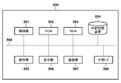
次にPC500について説明する。図6は、PC500の機能構成例を示すブロック図である。PC500はパーソナルコンピュータとして市販されている電子機器であってよい。 Next, the PC 500 will be explained. FIG. 6 is a block diagram showing a functional configuration example of the PC 500. As shown in FIG. The PC 500 may be an electronic device commercially available as a personal computer.

制御部501はプログラムを実行可能なプロセッサであり、例えばCPU(Central Processing Unit)である。ROM(Read Only Memory)502は例えば電気的に書き換え可能な不揮発性メモリである。ROM502は、制御部501が実行するプログラム、各種の設定値やパラメータを記憶する。RAM(Random Access Memory)503は、制御部501が実行するプログラムをロードしたり、さまざまなデータを一時的に記憶したりするために用いられる。RAM503に一部は、バッファメモリやビデオメモリとして用いられてもよい。 The control unit 501 is a processor capable of executing programs, such as a CPU (Central Processing Unit). A ROM (Read Only Memory) 502 is, for example, an electrically rewritable nonvolatile memory. The ROM 502 stores programs executed by the control unit 501, various setting values, and parameters. A RAM (Random Access Memory) 503 is used to load programs executed by the control unit 501 and temporarily store various data. A portion of the RAM 503 may be used as a buffer memory or video memory.

外部記憶装置504は、PC500が内蔵する大規模記憶装置である。外部記憶装置504は、代表的にはハードディスクドライブ(HDD)またはソリッドステートドライブ(SSD)である。外部記憶装置504はHDDまたはSSDに加え、メモリカードリーダなど、リムーバブルメディアを用いる記憶装置を含んでもよい。外部記憶装置504にはOS(Operating System)、アプリケーションプログラム、ユーザデータなどが記憶される。外部記憶装置504の一部はメモリスワップ領域として用いられてもよい。カメラ100から受信したり、メモリカードから読み込んだりすることによって取得した画像データファイルは、外部記憶装置504のHDDまたはSSDに格納される。 The external storage device 504 is a large-scale storage device built into the PC 500 . The external storage device 504 is typically a hard disk drive (HDD) or solid state drive (SSD). The external storage device 504 may include a storage device using removable media, such as a memory card reader, in addition to an HDD or SSD. An external storage device 504 stores an OS (Operating System), application programs, user data, and the like. A portion of the external storage device 504 may be used as a memory swap area. An image data file obtained by receiving from the camera 100 or reading from a memory card is stored in the HDD or SSD of the external storage device 504 .

操作部505は、キーボード、マウス、タッチパネルなど、ユーザが操作可能な入力デバイスの総称である。表示部506は例えば液晶ディスプレイ(LCD)であり、タッチパネルを有してもよい。表示部506は、PC500で稼働するOSやアプリケーションがさまざまな情報やデータを表示するために用いられる。 An operation unit 505 is a general term for input devices that can be operated by a user, such as a keyboard, a mouse, and a touch panel. The display unit 506 is, for example, a liquid crystal display (LCD) and may have a touch panel. A display unit 506 is used by the OS and applications running on the PC 500 to display various information and data.

通信部507は例えば外部機器と無線通信を行うための通信回路を有する。通信部507は無線通信規格の1つ以上に準拠している。無線通信規格としては例えばBluetooth(登録商標)や無線LAN(IEEE 802.11x)などが代表的であるが、これらに限定されない。 The communication unit 507 has, for example, a communication circuit for wireless communication with an external device. The communication unit 507 conforms to one or more wireless communication standards. Examples of wireless communication standards include Bluetooth (registered trademark) and wireless LAN (IEEE 802.11x), but are not limited to these.

外部I/F508は、例えば外部機器と有線通信を行うための通信回路を有する。外部I/F508は有線通信規格の1つ以上に準拠している。有線通信規格としては例えばUSB(Universal Serial Bus)、HDMI、Thunderbolt(登録商標)、イーサネット(登録商標)などが代表的であるが、これらに限定されない。
システムバス509は上述した各ブロックを相互に通信可能に接続する。
The external I/F 508 has, for example, a communication circuit for wired communication with an external device. The external I/F 508 conforms to one or more wired communication standards. Typical wired communication standards include, but are not limited to, USB (Universal Serial Bus), HDMI, Thunderbolt (registered trademark), Ethernet (registered trademark), and the like.
A system bus 509 connects the blocks described above so as to be able to communicate with each other.

次に、カメラ100の撮影動作について図7のフローチャートを用いて説明する。撮影動作は、システム制御部50がプログラムを実行して必要な制御を実行することによって実現される。図7に示す撮影動作は、例えば電源スイッチ102を操作することにより、ユーザがカメラ100の電源をオンにした際に開始される。システム制御部50は、電源オンに伴う起動処理を実行した後、カメラ100を撮影スタンバイ状態とする。撮影スタンバイ状態においてカメラ100は動画撮影を継続して行い、EVF217または表示部108にライブビュー表示を行うものとする。 Next, the photographing operation of camera 100 will be described using the flowchart of FIG. The photographing operation is realized by the system control unit 50 executing a program to perform necessary control. The shooting operation shown in FIG. 7 is started when the user turns on the power of the camera 100 by operating the power switch 102, for example. The system control unit 50 puts the camera 100 into a shooting standby state after executing the activation process associated with power-on. In the shooting standby state, the camera 100 continues to shoot moving images and displays live view on the EVF 217 or the display unit 108 .

S601でシステム制御部50は、撮像部211から動画像の1フレームに相当する画像信号を読み出し、A/D変換器212に出力する。
S602でシステム制御部50は、画像処理部214にライブビュー表示用の画像データを生成させる。画像処理部214は、ライブビュー表示用の画像データをメモリ215のビデオメモリ領域に格納する。D/A変換器216はメモリ215のビデオメモリ領域に格納された画像データをD/A変換し、EVF217および表示部108の少なくとも一方に表示させる。また、画像処理部214は画像データに基づいて評価値を生成し、システム制御部50に出力する。システム制御部50は、評価値に基づいて露出条件を決定したり、レンズユニットの合焦距離を調整したりすることができる。
In S<b>601 , the system control unit 50 reads an image signal corresponding to one frame of a moving image from the imaging unit 211 and outputs it to the A/D converter 212 .
In S602, the system control unit 50 causes the image processing unit 214 to generate image data for live view display. The image processing unit 214 stores the image data for live view display in the video memory area of the memory 215 . The D/A converter 216 D/A converts the image data stored in the video memory area of the memory 215 and displays it on at least one of the EVF 217 and the display unit 108 . Also, the image processing unit 214 generates an evaluation value based on the image data and outputs it to the system control unit 50 . The system control unit 50 can determine exposure conditions based on the evaluation value and adjust the focal length of the lens unit.

S603でシステム制御部50は、ユーザから記録開始指示がなされたか否かを判定する。システム制御部50は、例えば第2シャッタースイッチ信号SW2を検出した場合に、記録開始指示がなされたものと判定することができる。システム制御部50は、記録開始指示がなされたと判定されればS604を実行し、記録開始指示がなされたと判定されなければ次フレームのライブビュー表示のためにS601から再度実行する。このように、撮影スタンバイ状態において、システム制御部50は、記録開始指示がなされたと判定されるまで、ライブビュー表示動作を継続して実行する。なお、記録開始指示は、動画ボタン106の操作による動画記録の開始指示であってもよい。また、記録開始指示以外の指示を検出した場合、システム制御部50は指示に応じた動作を実行するが、その詳細については説明を省略する。 In S603, the system control unit 50 determines whether or not the user has issued a recording start instruction. For example, when the second shutter switch signal SW2 is detected, the system control unit 50 can determine that the recording start instruction has been issued. The system control unit 50 executes S604 if it is determined that the recording start instruction has been issued, and executes again from S601 for live view display of the next frame if it is not determined that the recording start instruction has been issued. In this manner, in the shooting standby state, the system control unit 50 continues to perform the live view display operation until it is determined that the recording start instruction has been issued. Note that the recording start instruction may be an instruction to start recording a moving image by operating the moving image button 106 . Further, when an instruction other than the recording start instruction is detected, the system control unit 50 executes an operation according to the instruction, but the details thereof will be omitted.

S604でシステム制御部50は、撮像部211から画像信号を読み出し、A/D変換器212に出力する。システム制御部50は、例えばライブビュー表示時よりも高解像度の画像信号を読み出す。システム制御部50は、画像処理部214に記録用の画像データを生成させる。画像処理部214は、記録用の画像データをメモリ215に格納する。 In S<b>604 , the system control unit 50 reads the image signal from the imaging unit 211 and outputs it to the A/D converter 212 . The system control unit 50 reads, for example, an image signal with a resolution higher than that during live view display. The system control unit 50 causes the image processing unit 214 to generate image data for recording. The image processing unit 214 stores image data for recording in the memory 215 .

S605でシステム制御部50は、撮像画像データのメタデータとして記録する情報を取得する。システム制御部50は例えば撮影条件(撮影時のカメラ100およびレンズユニットの設定、状態に関する情報)や、現像処理に用いるパラメータなどを取得することができる。これらは例示であり、他の情報を取得してもよい。撮影条件には例えばシャッタースピード、絞り値、ISO感度などの露出条件、フレームレート、解像度、データの圧縮形式、色空間、ガンマ値、カメラ100の姿勢、フラッシュ点灯有無などが含まれうる。動画データの場合には、動画ファイル中のフレーム開始位置を示す情報もメタデータに含まれる。また、レンズユニットからレンズ情報が取得できる場合、レンズ情報もメタデータに含めることができる。なお、ここで例示していない情報をメタデータとして記録してもよい。 In S605, the system control unit 50 acquires information to be recorded as metadata of the captured image data. The system control unit 50 can acquire, for example, shooting conditions (information on the settings and states of the camera 100 and the lens unit at the time of shooting), parameters used for development processing, and the like. These are examples, and other information may be obtained. The shooting conditions may include, for example, shutter speed, aperture value, exposure conditions such as ISO sensitivity, frame rate, resolution, data compression format, color space, gamma value, attitude of the camera 100, flash lighting, and the like. In the case of moving image data, the metadata also includes information indicating the frame start position in the moving image file. Also, if lens information can be obtained from the lens unit, the lens information can also be included in the metadata. Note that information not exemplified here may be recorded as metadata.

S606でシステム制御部50は、S604で画像処理部214が生成した記録用の画像データを格納したデータファイルを例えば記録媒体227に記録する。
S607でシステム制御部50は、S605で取得した情報を、画像データのメタデータとして、S606で記録したデータファイルに関連付けて記録する。本実施形態では、S606で記録したデータファイルにメタデータを記録する。
In S<b>606 , the system control unit 50 records the data file storing the image data for recording generated by the image processing unit 214 in S<b>604 in the recording medium 227 , for example.
In S607, the system control unit 50 records the information acquired in S605 as metadata of the image data in association with the data file recorded in S606. In this embodiment, metadata is recorded in the data file recorded in S606.

S608でシステム制御部50は、ユーザから記録終了指示がなされたか否かを判定する。システム制御部50は、例えば第2シャッタースイッチ信号SW2が検出されなければ、記録終了指示がなされたものと判定することができる。動画撮影の場合、システム制御部50は、例えば動画ボタン106の操作を検出すると、記録終了指示がなされたものと判定することができる。システム制御部50は、記録終了指示がなされたと判定されれば撮影動作を終了する。なお、システム制御部50は、撮影スタンバイ状態に戻るためにS601を実行してもよい。記録終了指示がなされたと判定されなければシステム制御部50はS604に戻って動画の次フレームまたは静止画の撮影を実行する。 In S608, the system control unit 50 determines whether or not the user has issued a recording end instruction. For example, if the second shutter switch signal SW2 is not detected, the system control unit 50 can determine that the recording end instruction has been given. In the case of moving image shooting, the system control unit 50 can determine that a recording end instruction has been issued, for example, when detecting an operation of the moving image button 106 . The system control unit 50 ends the shooting operation when it is determined that the recording end instruction has been issued. Note that the system control unit 50 may execute S601 to return to the shooting standby state. If it is determined that the recording end instruction has not been issued, the system control unit 50 returns to S604 to shoot the next frame of the moving image or the still image.

カメラ100に2眼レンズユニット300が装着されている場合、2つの円周魚眼像が左右に配置され(メッシュ、サイドバイサイド形式)、円周魚眼像の左右の位置関係が逆転しているVR180画像(静止画または動画)が記録される。なお、静止画および動画のデータ形式に特に制限はなく、RAW形式であっても、現像処理後の形式(JPEG形式やMPEG形式など)であってもよい。なお、撮像画像は、記録媒体227へ記録する代わりに、あるいは記録媒体227への記録に加えて、映像信号出力I/F240を通じてPC500に送信されてもよい。PC500は、通信部507または外部I/F508を通じて受信した画像データファイルを外部記憶装置504に格納する。 When the two-lens unit 300 is attached to the camera 100, two circular fisheye images are arranged on the left and right (mesh, side-by-side format), and the left and right positional relationships of the circular fisheye images are reversed. An image (still image or video) is recorded. The data format of still images and moving images is not particularly limited, and may be a RAW format or a format after development processing (JPEG format, MPEG format, etc.). Note that the captured image may be transmitted to the PC 500 through the video signal output I/F 240 instead of being recorded on the recording medium 227 or in addition to being recorded on the recording medium 227 . PC 500 stores the image data file received through communication unit 507 or external I/F 508 in external storage device 504 .

次に、PC500の画像データ表示動作について、図8のフローチャートを用いて説明する。以下の動作は、PC500において、制御部501が、外部記憶装置504に格納されている画像処理アプリケーションを実行することによって実現される。 Next, the image data display operation of the PC 500 will be described with reference to the flowchart of FIG. The following operations are realized in PC 500 by control unit 501 executing an image processing application stored in external storage device 504 .

ここでは、画像処理アプリケーションが表示部506に提示するGUIをユーザが操作部505を通じて操作することにより、処理対象の画像データファイルを選択し、処理の実行を指示したことを制御部501が検出したことに応じて動作を開始するものとする。なお、処理対象の画像データファイルは、例えば外部記憶装置504(HDD,SSD,またはメモリカード)に格納されている画像データファイルから選択されるものとする。 Here, the control unit 501 detects that the user has selected an image data file to be processed by operating the GUI presented on the display unit 506 by the image processing application through the operation unit 505, and instructed execution of processing. Action shall be initiated accordingly. It is assumed that the image data file to be processed is selected from image data files stored in the external storage device 504 (HDD, SSD, or memory card), for example.

S701で制御部501は、選択された画像データファイルから、ファイル内の画像データに関するメタデータを取得する。 In S701, the control unit 501 acquires metadata regarding image data in the selected image data file.

S702で制御部501は、必要に応じてS701で取得したメタデータを用い、画像データファイルから、処理を行う画像データをRAM503に読み込む。 In S<b>702 , the control unit 501 uses the metadata acquired in S<b>701 as necessary, and reads image data to be processed from the image data file into the RAM 503 .

S703で制御部501(画像処理手段)は、S702で読み込んだ画像データの種別を判定する。具体的には、制御部501は、画像データが2つの円周魚眼像を含んだ画像のデータであるか否かを判定する。この判定は、画像データがメッシュ形式のVR画像データであるか否かの判定に相当する。円周魚眼像を含んだ画像の場合、円周魚眼像以外の周辺領域は黒画素である。そのため、制御部501は例えば画像データの各画素の輝度値に、黒画素の輝度値に近い閾値を適用して二値化画像データを生成する。そして、制御部501(判定手段)は、二値化画像データが表す画像が、白の円形領域を2つ含んでいると判定されれば、S702で読み込んだ画像データの種別を、2つの円周魚眼像を含んだ画像のデータであると判定する。 In S703, the control unit 501 (image processing means) determines the type of the image data read in S702. Specifically, the control unit 501 determines whether the image data is image data including two circular fisheye images. This determination corresponds to determination of whether or not the image data is VR image data in mesh format. In the case of an image including a circular fisheye image, the peripheral area other than the circular fisheye image is black pixels. Therefore, the control unit 501 generates binarized image data by, for example, applying a threshold close to the luminance value of a black pixel to the luminance value of each pixel of the image data. Then, if it is determined that the image represented by the binarized image data includes two white circular regions, the control unit 501 (determining means) sets the type of the image data read in S702 to two circular regions. It is determined that the image data includes a circular fisheye image.

白領域が円形か否かは公知の任意の方法で判定することができる。例えば、白領域の外周の上の2点と交わる任意の直線を複数本引き、各直線の中点を通る垂線が1点で交わる場合には円形と判定することができる。ただし、実際には誤差が出ることを考慮し、複数の垂線の交点が一定の距離内に存在すれば円形領域と判定してもよい。 Whether or not the white area is circular can be determined by any known method. For example, if a plurality of arbitrary straight lines that intersect two points on the outer circumference of the white area are drawn, and perpendicular lines passing through the midpoints of the straight lines intersect at one point, it can be determined that the area is circular. However, considering that an error actually occurs, it may be determined that the area is a circular area if the intersection points of a plurality of perpendicular lines exist within a certain distance.

また、2つの円形領域が検出された場合、制御部501は、円形領域のサイズが同等であるか否か、円形領域間の距離が閾値未満であるか否かをさらに判定してもよい。そして、制御部501は、2つの円形領域のサイズが同等であること、および円形領域間の距離が閾値未満であることの少なくとも一方を満たす場合に、画像データが、2つの円周魚眼像を含んだVR画像データであると判定する。 Also, when two circular regions are detected, the control unit 501 may further determine whether the sizes of the circular regions are the same and whether the distance between the circular regions is less than a threshold. Then, if at least one of the two circular regions having the same size and the distance between the circular regions being less than a threshold is satisfied, the control unit 501 determines that the image data is the two circular fisheye images. It is determined that the VR image data includes

2つの円形領域のサイズが同等であること、円形領域間の距離が閾値未満であることは、それぞれ、画像データが2つの円周魚眼像を含んだVR画像データである可能性を高める条件である。円形領域のサイズは例えば領域内の画素数、または領域の外周上の2点を結ぶ直線の最大長であってよい。画素数もしくは最大長の差が閾値未満であれば、2つの円形領域のサイズは同等と判定することができる。また、円形領域間の距離は、2つの円形領域の外周間の最短距離であってよい。 That the two circular regions have the same size and that the distance between the circular regions is less than a threshold are conditions that increase the possibility that the image data is VR image data containing two circular fisheye images. is. The size of a circular area may be, for example, the number of pixels in the area, or the maximum length of a straight line connecting two points on the perimeter of the area. If the difference in the number of pixels or the maximum length is less than a threshold, it can be determined that the sizes of the two circular regions are the same. Also, the distance between the circular regions may be the shortest distance between the perimeters of the two circular regions.

別の方法を用いて、画像データが、2つの円周魚眼像を含んだVR画像データであると判定してもよい。例えば、制御部501は、画像を左領域と右領域に2分割するように画像データを分割する。そして、制御部501は、各領域について、閾値以上の画素で形成される部分領域を検出する。制御部501は、部分領域が円形領域であるか否かを上述した方法で判定する。右領域および左領域のそれぞれで円形領域が検出されれば、制御部501は、画像データが、2つの円周魚眼像を含んだVR画像データであると判定することができる。この場合も、2つの円形領域のサイズが同等であること、および円形領域間の距離が閾値未満であることの少なくとも一方を満たす場合に、画像データが、2つの円周魚眼像を含んだVR画像データであると判定するようにしてもよい。 Another method may be used to determine that the image data is VR image data containing two circular fisheye images. For example, the control unit 501 divides the image data so as to divide the image into a left area and a right area. Then, the control unit 501 detects a partial area formed by pixels equal to or larger than the threshold for each area. The control unit 501 determines whether or not the partial area is a circular area by the method described above. If a circular area is detected in each of the right area and the left area, the control unit 501 can determine that the image data is VR image data including two circular fisheye images. Also in this case, the image data contains two circular fisheye images when at least one of the two circular regions having the same size and the distance between the circular regions being less than a threshold is satisfied. It may be determined that the data is VR image data.

制御部501は、処理対象の画像データが2つの円周魚眼像を含んだ画像のデータであると判定されればS704を、判定されなければS707を実行する。 The control unit 501 executes S704 if it is determined that the image data to be processed is data of an image containing two circular fisheye images, and otherwise executes S707.

なお、撮像部211の有効画素領域のサイズが小さい場合、図12(b)に示すように、右眼光学系301Rおよび左眼光学系301Lが形成する被写体像(円周魚眼像)1221の一部が欠けた画像1220が記録されうる。円周魚眼像の端部が欠けていても、中心部分を用いることでVR画像を表示再生できる。ただし、円周魚眼像に欠けがない場合よりもVR画像の視野角は狭くなる。 Note that when the size of the effective pixel area of the imaging unit 211 is small, as shown in FIG. A partially missing image 1220 can be recorded. Even if the end portion of the circular fisheye image is missing, the VR image can be displayed and reproduced by using the central portion. However, the viewing angle of the VR image is narrower than when the circular fisheye image is not lacking.

白領域1221が画像1220の端部に達している場合、白領域1221の外周のうち、画像1220の端部1222を形成しない部分を用い、上述した方法で白領域1221が円形領域の一部であるか否かを判定することができる。すなわち、白領域1221の外周のうち、画像1220の端部1222を形成しない部分に含まれる2点と交わる任意の直線を複数本引き、各直線の中点を通る垂線が1点で交わる場合には白領域1221が円形領域の一部であると判定することができる。白領域1221が円形領域の一部であると判定されれば、画像1220は円周魚眼像の一部を含んでいると判定することができる。 When the white region 1221 reaches the edge of the image 1220, the portion of the periphery of the white region 1221 that does not form the edge 1222 of the image 1220 is used, and the white region 1221 is part of the circular region by the method described above. It can be determined whether there is In other words, if a plurality of arbitrary straight lines that intersect two points included in the portion that does not form the edge 1222 of the image 1220 are drawn from the periphery of the white region 1221, and the perpendiculars that pass through the midpoints of the straight lines intersect at one point, can determine that the white area 1221 is part of the circular area. If it is determined that the white area 1221 is part of a circular area, then it can be determined that the image 1220 contains part of a circular fisheye image.

例えば、制御部501はS703において、画像が2つの円周魚眼像を含んでいると判定されない場合、一部が欠けた円周魚眼像を2つ含んでいるか否かをさらに判定することができる。そして、制御部501は、画像が一部が欠けた円周魚眼像を2つ含んでいると判定された場合、画像が2つの円周魚眼像を含んでいるとみなして、S704以降の処理を実行してもよい。この場合、S703は画像データが少なくとも部分的な円周魚眼像を2つ含んでいるか否かの判定、S704~S706は少なくとも部分的な円周魚眼像を対象とした処理と見なすことができる。 For example, if it is not determined in S703 that the image includes two circular fisheye images, the control unit 501 further determines whether or not the image includes two partially missing circular fisheye images. can be done. Then, when it is determined that the image includes two partially-missing circular fisheye images, the control unit 501 regards the image as including two circular fisheye images, and determines that the image includes two circular fisheye images. may be performed. In this case, S703 can be regarded as a determination as to whether or not the image data includes at least two partial circular fisheye images, and S704 to S706 can be regarded as processing for at least partial circular fisheye images. can.

S704で制御部501は、画像に含まれる2つの円周魚眼像の中心座標と半径を決定する。円の弦の垂直2等分線は円の中心を通るため、円形と判定された白領域の円周の上の2点と交わる任意の直線を2本引き、各直線の垂線2等分線の交点を白領域の中心座標とすることができる。 In S704, the control unit 501 determines the center coordinates and radii of the two circular fisheye images included in the image. Since the perpendicular bisector of the chord of a circle passes through the center of the circle, draw two arbitrary straight lines that intersect the two points on the circumference of the white area determined to be circular, and find the perpendicular bisector of each straight line. can be used as the center coordinates of the white area.

図12(a)を用いて、具体例を説明する。例えばS703で画像1200のデータから検出された2つの円形領域1201のそれぞれについて、任意の縦位置(Y座標)で水平方向に画素値を調べ、黒から白に変化した画素のX座標X1と、白から黒に変換した画素のX座標X2を求める。また、任意の横位置(X座標)で垂直方向に画素値を調べ、黒から白に変化した画素のY座標Y1と、白から黒に変換した画素のY座標Y2を求める。このとき、円形領域1201の中心座標1202(X0,Y0)は、X座標(X0)が(X1+X2)/2、Y座標(Y0)が(Y1+Y2)/2である。また、中心座標から水平方向に画素値を調べ、白から黒に変化した画素のX座標をX3とすると、円の半径は、X3-((X1+X2)/2)で求められる。中心座標は例えば画像内の一点(例えば画像中心)を原点とする画像座標として算出する。なお、図12(b)に示したような、一部が欠けた円形領域1221についても、画像の端部を形成する部分1222を除く円周上の部分を用いて同様に中心座標および半径を求めることができる。 A specific example will be described with reference to FIG. For example, for each of the two circular regions 1201 detected from the data of the image 1200 in S703, the pixel value is checked horizontally at an arbitrary vertical position (Y coordinate), and the X coordinate X1 of the pixel that changed from black to white, Obtain the X coordinate X2 of the pixel converted from white to black. Also, the pixel value is examined in the vertical direction at an arbitrary horizontal position (X coordinate), and the Y coordinate Y1 of the pixel changed from black to white and the Y coordinate Y2 of the pixel changed from white to black are obtained. At this time, the center coordinates 1202 (X0, Y0) of the circular area 1201 have an X coordinate (X0) of (X1+X2)/2 and a Y coordinate (Y0) of (Y1+Y2)/2. Further, if the pixel value is checked in the horizontal direction from the center coordinates and the X coordinate of the pixel that has changed from white to black is X3, then the radius of the circle can be obtained by X3-((X1+X2)/2). The central coordinates are calculated, for example, as image coordinates with one point in the image (for example, the center of the image) as the origin. It should be noted that the central coordinates and the radius of a circular area 1221 with a part missing as shown in FIG. can ask.

なお、ここで説明した方法は一例であり、他の画像処理によって円周魚眼像の中心座標と半径を算出してもよい。また、誤差を考慮し、1つの円形領域について、2直線の異なる複数の組み合わせのそれぞれから得られる中心座標の平均座標を最終的な中心座標としてもよい。同様に、半径についても中心座標から複数の方向について算出した結果を平均して求めてもよい。 The method described here is only an example, and the center coordinates and radius of the circular fisheye image may be calculated by other image processing. In consideration of errors, the final center coordinates may be the average coordinates of the center coordinates obtained from a plurality of different combinations of two straight lines for one circular area. Similarly, the radius may also be obtained by averaging the results calculated in a plurality of directions from the center coordinates.

S705で制御部501(生成手段)は、S704で求めた2つの円形領域の中心座標と半径を用いて、画像データから右像および左像に相当する2つの円形領域の画像を抽出する。制御部501は、円形領域が欠けないよう、周囲の黒領域を含むように抽出してもよい。そして、制御部501は、右像および左像の配置を左右入れ替えた画像データを生成する。なお、制御部501は、配置を入れ替えた後も、S704で求めた左右の円形領域の中心座標が保持されるように抽出した円形領域の画像を配置する。例えば、画像の左側から抽出した円形領域(右像)は、その中心座標が画像の右側の円形領域(左像)について算出された中心座標と一致するように配置する。画像の左側から抽出した円形領域についても同様である。 In S705, the control unit 501 (generating means) extracts images of two circular regions corresponding to the right and left images from the image data using the center coordinates and radii of the two circular regions obtained in S704. The control unit 501 may extract a surrounding black area so that the circular area is not missing. Then, the control unit 501 generates image data in which the positions of the right image and the left image are interchanged. Note that the control unit 501 arranges the images of the extracted circular areas so that the center coordinates of the left and right circular areas obtained in S704 are maintained even after the arrangement is changed. For example, a circular area (right image) extracted from the left side of the image is arranged so that its central coordinates match the central coordinates calculated for the circular area (left image) on the right side of the image. The same is true for the circular area extracted from the left side of the image.

あるいは、配置を入れ替えた後の画像における右眼座標および左眼座標が既知の場合、右眼座標を基準として右像の配置位置を決定し、左眼座標を基準として左像の配置位置を決定してもよい。 Alternatively, if the right-eye coordinates and left-eye coordinates of the image after the arrangement is exchanged are known, the arrangement position of the right image is determined based on the right-eye coordinates, and the arrangement position of the left image is determined based on the left-eye coordinates. You may

S706で制御部501は、S705で生成した、円周魚眼像の配置を入れ替えたVR180画像データを、表示部506に表示したり、通信部507または外部I/F508を通じて接続されたVRゴーグルなどの立体表示装置に出力したりする。なお、VR180画像データを表示する場合など、制御部501は必要に応じて円周魚眼像に正距円筒変換を適用してメッシュ形式からエクイレクタングラー形式への変換などを行ってもよい。 In S706, the control unit 501 displays the VR180 image data generated in S705 in which the arrangement of the circular fisheye image is replaced on the display unit 506, or displays the VR goggles or the like connected through the communication unit 507 or the external I/F 508. output to a 3D display device. Note that when displaying VR180 image data, the control unit 501 may apply equirectangular transformation to the circular fisheye image as necessary to convert from the mesh format to the equirectangular format.

S707で制御部501は、S702で取得した画像データをそのまま表示部506に表示する。 In S707, the control unit 501 displays the image data acquired in S702 on the display unit 506 as it is.

図8では、S706およびS707が終了すると、表示動作を終了するように記載しているが、S701に処理を戻して、別の画像データについての処理が指示されるのを待機してもよい。また、処理対象の画像データがVR180動画データの場合には、各フレームについてS704~S706の処理を繰り返し実施する。動画データについては、先頭フレームに対するS703、S704の処理結果を2フレーム以降に流用できるため、2フレーム以降についてはS704を省略できる。 Although FIG. 8 shows that the display operation ends when S706 and S707 are finished, the process may return to S701 and wait for an instruction to process another image data. Also, when the image data to be processed is VR180 moving image data, the processing of S704 to S706 is repeatedly performed for each frame. As for the moving image data, the processing results of S703 and S704 for the first frame can be used for the second and subsequent frames, so S704 can be omitted for the second and subsequent frames.

なお、S704~S706の任意のタイミングで、右像と左像の配置を入れ替えるか否かをユーザに指定させるようにしてもよい。配置を入れ替えないように指定された場合、制御部501はS702で取得した画像データをそのまま表示する。なお、S703で画像が2つの円周魚眼像を含まないと判定された場合、一部が欠けた円周魚眼像を2つ含んでいるか否かを判定してもよい。そして、画像が一部が欠けた円周魚眼像を2つ含んでいると判定された場合は、一部が欠けた円周魚眼像に対してS704以降の処理を適用してもよい。 It should be noted that the user may specify whether or not to exchange the positions of the right image and the left image at an arbitrary timing of S704 to S706. If it is specified not to change the arrangement, the control unit 501 displays the image data acquired in S702 as it is. Note that if it is determined in S703 that the image does not include two circular fisheye images, it may be determined whether or not the image includes two partially missing circular fisheye images. Then, if it is determined that the image includes two partially-missing circular fisheye images, the processing from S704 onward may be applied to the partially-missing circular fisheye images. .

また、処理対象の画像データがVR180画像データか否かの情報がメタデータに含まれていない場合でも、一般的な撮影情報として、レンズユニットの機種名がメタデータに含まれる場合がある。この場合、S701においてレンズユニットの機種名を読み込み、予め登録されているVR180レンズの機種名リストを参照することにより、画像データの種別の判定、すなわち、VR180レンズを用いて撮影された画像データか否かの判定が可能である。この場合、S703の判定は画像処理を行わず実施できる。制御部501は、VR180レンズを用いて撮影された画像データであればS704を、他のレンズを用いて撮影された画像データであればS707を実行すればよい。 Even if the metadata does not include information about whether the image data to be processed is VR180 image data, the metadata may include the model name of the lens unit as general shooting information. In this case, in step S701, the model name of the lens unit is read, and the model name list of the VR180 lens registered in advance is referenced to determine the type of image data. It is possible to determine whether or not In this case, the determination in S703 can be performed without image processing. The control unit 501 may execute S704 for image data captured using the VR180 lens, and S707 for image data captured using another lens.

また、制御部501は、右像および左像の配置を入れ替えた画像データおよび、右像および左像の配置を入れ替え、さらに右像および左像に正距円筒変換を適用した画像データの少なくとも一方を別画像ファイルとして外部記憶装置504に保存してもよい。これらの画像データは、VRゴーグルなどの一般的なVR180対応機器でそのまま取り扱うことができる。 In addition, the control unit 501 controls at least one of image data in which the positions of the right and left images are interchanged, and image data in which the positions of the right and left images are interchanged and equirectangular transformation is applied to the right and left images. may be stored in the external storage device 504 as another image file. These image data can be handled as they are by general VR180 compatible devices such as VR goggles.

これらの画像データを別途保存する場合、画像データファイルに記録するメタデータとして、画像データがVR180画像データであること、右像と左像の配置が入れ替え済であること、正距円筒変換済みであることの1つ以上を示す情報を記録することができる。これにより、画像データを用いるVRシステムにおける処理を簡略化できる。 When these image data are saved separately, the metadata recorded in the image data file is that the image data is VR180 image data, that the positions of the right and left images have been switched, and that the equirectangular conversion has been completed. Information indicating one or more things can be recorded. This simplifies processing in a VR system that uses image data.

本実施形態では、カメラ100が2眼レンズユニット300から、2眼レンズユニット300がVR180レンズであることを示す情報を取得できないことを前提とした。カメラ100が2眼レンズユニット300から取得可能な情報に基づいて2眼レンズユニット300がVR180レンズであると判定できる場合、VR180画像データであることを示す情報をメタデータとして画像データファイルに記録することができる。これにより、PC500はS703の判定を画像処理を行わず実施できる。制御部501は、VR180レンズを用いて撮影された画像データであればS704を、他のレンズを用いて撮影された画像データであればS707を実行すればよい。 In this embodiment, it is assumed that the camera 100 cannot acquire information from the twin lens unit 300 indicating that the twin lens unit 300 is a VR180 lens. When the camera 100 can determine that the twin-lens unit 300 is a VR180 lens based on information that can be acquired from the twin-lens unit 300, information indicating VR180 image data is recorded in the image data file as metadata. be able to. As a result, the PC 500 can perform the determination of S703 without image processing. The control unit 501 may execute S704 for image data captured using the VR180 lens, and S707 for image data captured using another lens.

さらに、2眼レンズユニット300が形成する円周魚眼像(右像および左像)の中心座標や半径を2眼レンズユニット300から取得できる場合、これらの情報もメタデータとして画像データファイルに記録することができる。制御部501は、S701で取得したメタデータに円周魚眼像(右像および左像)の中心座標や半径の情報が含まれている場合、S703,S704の処理をスキップすることができる。そのため、制御部501は、S703を実行する前のタイミングで、S701で取得したメタデータに円周魚眼像(右像および左像)の中心座標や半径の情報が含まれているか否かを判定してもよい。そして、制御部501は、円周魚眼像(右像および左像)の中心座標や半径の情報が含まれていないと判定される場合にS703を実行し、含まれていると判定されればS705を実行する。 Furthermore, if the center coordinates and radius of the circular fisheye images (right and left images) formed by the twin-lens unit 300 can be obtained from the twin-lens unit 300, this information is also recorded in the image data file as metadata. can do. The control unit 501 can skip the processing of S703 and S704 when the metadata acquired in S701 includes information on the center coordinates and radius of the circular fisheye images (right and left images). Therefore, the control unit 501 checks at a timing before executing S703 whether or not the metadata acquired in S701 includes information on the center coordinates and radius of the circular fisheye images (right and left images). You can judge. Then, the control unit 501 executes S703 when it is determined that information about the center coordinates and radius of the circular fisheye images (right image and left image) is not included, and determines that the information is included. If so, S705 is executed.

以上説明したように、本実施形態によれば、画像データが2つの円周魚眼像を含んだ画像のデータであると判定される場合に、画像データの種別をVR180画像データであると判定するようにした。そのため、画像データのメタデータからはVR180画像データであるか否か判定できない場合であっても、画像の種別を正しく認識し、VR180画像データを適切に処理することが可能になる。したがって、カメラが装着されたレンズユニットがVR180レンズであることを認識できない場合であっても、カメラが記録した画像データの種別を正しく認識し、適切に取り扱うことができる。 As described above, according to the present embodiment, when image data is determined to be image data including two circular fisheye images, the type of image data is determined to be VR180 image data. I made it Therefore, even if it is not possible to determine whether the image data is VR180 image data from the metadata of the image data, it is possible to correctly recognize the image type and appropriately process the VR180 image data. Therefore, even if it is not possible to recognize that the lens unit attached to the camera is a VR180 lens, the type of image data recorded by the camera can be correctly recognized and handled appropriately.

●(第2実施形態)
次に、本発明の第2実施形態について説明する。第2実施形態は、2眼レンズユニット300を装着したカメラ100からPC500に、撮像素子から読み出した画像信号を映像信号としてリアルタイムに送信する形態に関する。以下の説明において、第1実施形態と共通する構成については第1実施形態と同じ参照符号を用いることにより、説明を省略する。
● (Second embodiment)
Next, a second embodiment of the invention will be described. The second embodiment relates to an embodiment in which an image signal read out from an imaging device is transmitted in real time as a video signal from a camera 100 equipped with a twin-lens unit 300 to a PC 500 . In the following description, the same reference numerals as in the first embodiment are used for the configurations common to the first embodiment, and the description is omitted.

図9は、第2実施形態に係る画像処理システムの模式図である。本実施形態の画像処理システムは、カメラ100とPC500とがケーブル190で接続され、カメラ100の撮像部211(撮像素子)から読みされた画像信号がリアルタイムでPC500に送信される構成を有する。ケーブル190は例えばカメラ100の映像信号出力I/F240とPC500の外部I/F508とを接続する。ここでは一例として画像信号をHDMI規格に準拠した伝送方法でカメラ100からPC500に送信するものとする。したがって、映像信号出力I/F240および外部I/F508はHDMI規格に準拠したインタフェースであり、ケーブル190はHDMIケーブルである。しかし、DVI(Diginal Visual Interface)、SDI、USB Video Classなどの他の規格に従って映像信号を送信してもよい。 FIG. 9 is a schematic diagram of an image processing system according to the second embodiment. The image processing system of this embodiment has a configuration in which a camera 100 and a PC 500 are connected by a cable 190, and an image signal read from an imaging unit 211 (image sensor) of the camera 100 is transmitted to the PC 500 in real time. The cable 190 connects the video signal output I/F 240 of the camera 100 and the external I/F 508 of the PC 500, for example. Here, as an example, it is assumed that the image signal is transmitted from the camera 100 to the PC 500 by a transmission method conforming to the HDMI standard. Therefore, the video signal output I/F 240 and the external I/F 508 are interfaces complying with the HDMI standard, and the cable 190 is an HDMI cable. However, video signals may be transmitted according to other standards such as DVI (Digital Visual Interface), SDI, USB Video Class, and the like.

PC500は外部I/F508を介して受信した映像信号を表示部506にリアルタイム表示することができる。また、PC500は、受信した映像信号をストリーミング可能な形式に変換し、PC500に接続されたHMD191に送信したり、クラウドサービス192を介して複数のユーザ193に対して配信したりすることができる。 The PC 500 can display the video signal received via the external I/F 508 on the display unit 506 in real time. Also, the PC 500 can convert the received video signal into a streamable format, transmit it to the HMD 191 connected to the PC 500 , or distribute it to a plurality of users 193 via the cloud service 192 .

次に、本実施形態におけるカメラ100の映像出力動作について図10のフローチャートを用いて説明する。図10において、第1実施形態で説明した撮影処理と同様の処理を行う工程については図7と同じ参照符号を付して説明を省略する。映像出力動作は、システム制御部50がプログラムを実行して必要な制御を実行することによって実現される。図10に示す撮影動作は、例えば電源スイッチ102を操作することにより、ユーザがカメラ100の電源をオンにした際に開始される。システム制御部50は、電源オンに伴う起動処理を実行した後、カメラ100を撮影スタンバイ状態とする。 Next, the video output operation of the camera 100 according to this embodiment will be described using the flowchart of FIG. In FIG. 10, the same reference numerals as in FIG. 7 are given to the steps of performing the same processing as the photographing processing described in the first embodiment, and the description thereof will be omitted. The video output operation is realized by the system control unit 50 executing a program to perform necessary control. The shooting operation shown in FIG. 10 is started when the user turns on the power of the camera 100 by operating the power switch 102, for example. The system control unit 50 puts the camera 100 into a shooting standby state after executing the activation process associated with power-on.

撮影スタンバイ状態においてカメラ100は動画撮影を継続して行い、EVF217または表示部108にライブビュー表示を行うものとする(S601~S602)。
S903でシステム制御部50は、映像信号出力I/F240にケーブル190が接続されたか否かを、信号線の電圧に基づいて判定する。システム制御部50は、ケーブル190が接続されたと判定された場合はS604を、判定されない場合はS601を実行する。
In the shooting standby state, the camera 100 continues to shoot moving images and displays live view on the EVF 217 or the display unit 108 (S601-S602).
In S903, the system control unit 50 determines whether or not the cable 190 is connected to the video signal output I/F 240 based on the voltage of the signal line. The system control unit 50 executes S604 when it is determined that the cable 190 is connected, and executes S601 when it is not determined.

S604でシステム制御部50は、1フレーム分の画像信号を読み出し、画像処理部214に表示用画像データを生成させる。また、S605でシステム制御部50は、メタデータとしてPC500に送信する情報を取得する。本実施形態でもシステム制御部50は2眼レンズユニット300がVR180レンズであることを判定可能な情報を2眼レンズユニット300から取得できないものとする。 In S604, the system control unit 50 reads the image signal for one frame and causes the image processing unit 214 to generate image data for display. Also, in S605, the system control unit 50 acquires information to be transmitted to the PC 500 as metadata. Also in this embodiment, the system control unit 50 cannot acquire information from the twin lens unit 300 that can determine that the twin lens unit 300 is a VR180 lens.

S906でシステム制御部50は、カメラ100におけるライブビュー表示のための動作と並行して、例えばメモリ215の一部領域として用意したHDMI信号出力用のバッファに画像データとメタデータを所定の形式で格納する。 In S906, in parallel with the operation for live view display in the camera 100, the system control unit 50 stores image data and metadata in a predetermined format in an HDMI signal output buffer prepared as a partial area of the memory 215, for example. Store.

S907でシステム制御部50は、バッファに格納された画像データとメタデータとを、映像信号出力I/F240を通じてHDMI信号として出力する。データをHDMI信号(TMDSシーケンス)に変換するためのエンコード処理などの詳細については説明を省略する。 In S<b>907 , the system control unit 50 outputs the image data and metadata stored in the buffer as HDMI signals through the video signal output I/F 240 . Description of details such as encoding processing for converting data into an HDMI signal (TMDS sequence) is omitted.

S908でシステム制御部50は、映像信号出力I/F240からケーブル190が抜かれたか否か、信号線の電圧に基づいて判定する。ケーブル190が抜かれたと判定された場合は映像出力動作を終了する。システム制御部50は、ケーブル190が抜かれたと判定されない場合はS604からの処理を繰り返す。これにより、ライブビュー画像がPC500の表示部506に継続して表示される。 In S908, the system control unit 50 determines whether or not the cable 190 has been removed from the video signal output I/F 240 based on the voltage of the signal line. If it is determined that the cable 190 has been pulled out, the video output operation is terminated. If it is not determined that the cable 190 has been pulled out, the system control unit 50 repeats the processing from S604. As a result, live view images are continuously displayed on the display unit 506 of the PC 500 .

本実施形態では、カメラ100にはVR180レンズである2眼レンズユニット300が装着されている。そのため、PC500には、2つの円周魚眼像を含んだVR180画像であって、右像と左像との位置が逆転した画像(図5の撮像画像402bに相当)の映像信号がPC500に出力される。なお、PC500に出力される画像データの信号形式は、RGB形式、YCbCr形式、RAW形式のいずれでもよい。RAW形式の場合にはS906で表示用画像データではなくRAWデータをバッファに格納する。なお、画像処理部214が生成する表示用画像データはカメラ100の表示デバイスの解像度に合わせた解像度を有する。PC500に送信するための画像データは、PC500の表示解像度を考慮した解像度としてもよい。 In this embodiment, the camera 100 is equipped with a twin lens unit 300 that is a VR180 lens. Therefore, the PC 500 receives a video signal of a VR180 image including two circular fisheye images in which the positions of the right image and the left image are reversed (corresponding to the captured image 402b in FIG. 5). output. The signal format of the image data output to the PC 500 may be RGB format, YCbCr format, or RAW format. In the case of the RAW format, the RAW data is stored in the buffer instead of the display image data in S906. Note that the display image data generated by the image processing unit 214 has a resolution that matches the resolution of the display device of the camera 100 . Image data to be transmitted to the PC 500 may have a resolution that takes into consideration the display resolution of the PC 500 .

次に、PC500の映像表示動作について、図11のフローチャートを用いて説明する。以下の動作は、PC500において、制御部501が、外部記憶装置504に格納されている画像処理アプリケーションを実行することによって実現される。図11において、第1実施形態で説明した画像データ表示動作と同様の処理を行う工程については図8と同じ参照符号を付して説明を省略する。ここでは、外部I/F508とカメラ100の映像信号出力I/F240とがケーブル190で接続され、PC500がカメラ100から映像信号を受信可能な状態であるものとする。 Next, the video display operation of the PC 500 will be explained using the flowchart of FIG. The following operations are realized in PC 500 by control unit 501 executing an image processing application stored in external storage device 504 . In FIG. 11, steps for performing processing similar to the image data display operation described in the first embodiment are denoted by the same reference numerals as in FIG. 8, and description thereof is omitted. Here, it is assumed that the external I/F 508 and the video signal output I/F 240 of the camera 100 are connected by a cable 190 so that the PC 500 can receive video signals from the camera 100 .

S1001で制御部501は、外部I/F508を通じて映像信号を受信したか否かを判定する。制御部501は、映像信号を受信したと判定された場合はS1002を実行し、判定されない場合はS1001を実行する。 In S<b>1001 , the control unit 501 determines whether or not a video signal has been received through the external I/F 508 . The control unit 501 executes S1002 when it is determined that the video signal has been received, and executes S1001 when it is not determined.

S1002で制御部501は、外部I/F508を通じた映像信号の受信が停止したか否かを判定する。制御部501は、映像信号の受信が停止した判定された場合は映像表示動作を終了し、判定されない場合はS1003を実行する。 In S1002, the control unit 501 determines whether the reception of the video signal through the external I/F 508 has stopped. The control unit 501 ends the video display operation when it is determined that the reception of the video signal has stopped, and executes S1003 when it is not determined.

S1003で制御部501は、受信した映像信号をデコードしてメタデータを取得する。
S1004で制御部501は、受信した映像信号をデコードして画像データを取得する。
以降、制御部501は、第1実施形態で説明したS703以降の処理を実行する。
In S1003, the control unit 501 decodes the received video signal to acquire metadata.
In S1004, the control unit 501 decodes the received video signal to obtain image data.
Thereafter, the control unit 501 executes the processes after S703 described in the first embodiment.

なお、S704~S706の任意のタイミングで、右像と左像の配置を入れ替えるか否かをユーザに指定させるようにしてもよい。配置を入れ替えないように指定された場合、制御部501はS1004で取得した画像データをそのまま表示する。 It should be noted that the user may specify whether or not to exchange the positions of the right image and the left image at an arbitrary timing of S704 to S706. If it is specified not to change the arrangement, the control unit 501 displays the image data acquired in S1004 as it is.

また、S706において、右像および左像の配置を入れ替えた画像データの右像および左像に正距円筒変換を適用してメッシュ形式からエクイレクタングラー形式へ変換してから表示を行ってもよい。メッシュ形式とエクイレクタングラー形式のいずれを表示するかは、ユーザが指定できるようにしてもよい。 Further, in S706, equirectangular transformation may be applied to the right and left images of the image data in which the positions of the right and left images are interchanged to convert from the mesh format to the equirectangular format before displaying. . The user may be allowed to specify whether to display the mesh format or the equirectangular format.

また、処理対象の画像データがVR180画像データか否かの情報がメタデータに含まれていない場合でも、一般的な撮影情報として、レンズユニットの機種名がメタデータに含まれる場合がある。この場合、S1003においてレンズユニットの機種名を読み込み、予め登録されているVR180レンズの機種名リストを参照することにより、処理対象の画像データの種別判定(VR180レンズを用いて撮影された画像データか否かの判定)が可能である。この場合、S703の判定は画像処理を行わず実施できる。制御部501は、VR180レンズを用いて撮影された画像データであればS704を、他のレンズを用いて撮影された画像データであればS707を実行すればよい。 Even if the metadata does not include information about whether the image data to be processed is VR180 image data, the metadata may include the model name of the lens unit as general shooting information. In this case, in step S1003, the model name of the lens unit is read, and the model name list of the VR180 lens registered in advance is referenced to determine the type of image data to be processed (whether it is image data captured using the VR180 lens). or not) is possible. In this case, the determination in S703 can be performed without image processing. The control unit 501 may execute S704 for image data captured using the VR180 lens, and S707 for image data captured using another lens.

また、本実施形態でPC500が受信する映像信号は動画データに相当するため、先頭フレームに対するS703、S704の処理結果を2フレーム以降に流用できる。したがって、2フレーム以降についてはS704を省略できる。 In addition, since the video signal received by the PC 500 in this embodiment corresponds to moving image data, the processing results of S703 and S704 for the first frame can be used for the second and subsequent frames. Therefore, S704 can be omitted for the second and subsequent frames.

また、右像および左像の配置を入れ替えた画像データの右像および左像に正距円筒変換を適用してメッシュ形式からエクイレクタングラー形式へ変換した画像データをストリーミング可能な形式に変換し、外部に供給してもよい。例えば、制御部501は、ストリーミング可能な形式の画像データをPC500に接続されたHMDに送信したり、通信部507または外部I/F508を介して配信サーバに送信することができる。これにより、カメラ100のライブビュー画像を外部装置に供給したり、遠隔地のユーザに配信したりすることができる。 In addition, applying equirectangular transformation to the right and left images of the image data in which the positions of the right and left images are exchanged, converting the image data converted from the mesh format to the equirectangular format into a format that can be streamed, It may be supplied externally. For example, the control unit 501 can transmit image data in a streamable format to an HMD connected to the PC 500 or to a distribution server via the communication unit 507 or the external I/F 508 . As a result, the live view image of the camera 100 can be supplied to an external device or distributed to a remote user.

また、PC500が受信した映像信号をそのままストリーミング可能な形式に変換し、S703~S706に対応する処理を、外部装置(配信サーバやHMDなど)で実施してもよい。 Also, the video signal received by the PC 500 may be directly converted into a streamable format, and the processing corresponding to S703 to S706 may be performed by an external device (distribution server, HMD, etc.).

本実施形態では、カメラ100が2眼レンズユニット300から、2眼レンズユニット300がVR180レンズであることを示す情報を取得できないことを前提とした。しかしながら、カメラ100が2眼レンズユニット300から取得可能な情報に基づいて2眼レンズユニット300がVR180レンズであると判定できる場合、VR180画像データであることを示す情報をメタデータとして映像信号に含めることができる。これにより、PC500はS703の判定を画像処理を行わず実施できる。制御部501は、VR180レンズを用いて撮影された画像データであればS704を、他のレンズを用いて撮影された画像データであればS707を実行すればよい。 In this embodiment, it is assumed that the camera 100 cannot acquire information from the twin lens unit 300 indicating that the twin lens unit 300 is a VR180 lens. However, if the camera 100 can determine that the twin-lens unit 300 is a VR180 lens based on information that can be acquired from the twin-lens unit 300, information indicating VR180 image data is included in the video signal as metadata. be able to. As a result, the PC 500 can perform the determination of S703 without image processing. The control unit 501 may execute S704 for image data captured using the VR180 lens, and S707 for image data captured using another lens.

さらに、2眼レンズユニット300が形成する円周魚眼像(右像および左像)の中心座標や半径を2眼レンズユニット300から取得できる場合、これらの情報もメタデータとして画像データファイルに記録することができる。制御部501は、S1003で取得したメタデータに円周魚眼像(右像および左像)の中心座標や半径の情報が含まれている場合、S703,S704の処理をスキップすることができる。そのため、制御部501は、S703を実行する前のタイミングで、S1003で取得したメタデータに円周魚眼像(右像および左像)の中心座標や半径の情報が含まれているか否かを判定してもよい。そして、制御部501は、円周魚眼像(右像および左像)の中心座標や半径の情報が含まれていないと判定される場合にS703を実行し、含まれていると判定されればS705を実行する。 Furthermore, if the center coordinates and radius of the circular fisheye images (right and left images) formed by the twin-lens unit 300 can be obtained from the twin-lens unit 300, this information is also recorded in the image data file as metadata. can do. The control unit 501 can skip the processing of S703 and S704 when the metadata acquired in S1003 includes information on the center coordinates and radius of the circular fisheye images (right and left images). Therefore, at a timing before executing S703, the control unit 501 determines whether or not the metadata acquired in S1003 includes information about the center coordinates and radius of the circular fisheye images (right and left images). You can judge. Then, the control unit 501 executes S703 when it is determined that the information about the center coordinates and the radius of the circular fisheye images (right and left images) is not included, and determines that they are included. If so, S705 is executed.

以上説明したように、本実施形態によれば、カメラからリアルタイムで送信される映像信号で伝送される画像データが2つの円形領域を含んだ画像のデータであると判定される場合に、画像データの種別をVR180画像データであると判定するようにした。そのため、画像データのメタデータからはVR180画像データであるか否か判定できない場合であっても、VR180画像データを適切に処理することが可能になる。したがって、カメラが装着されたレンズユニットがVR180レンズであることを認識できない場合であっても、カメラから受信した画像の種別を正しく認識し、適切に取り扱うことができる。 As described above, according to the present embodiment, when it is determined that the image data transmitted by the video signal transmitted in real time from the camera is image data including two circular areas, the image data is determined to be VR180 image data. Therefore, even if it is not possible to determine whether the image data is VR180 image data from the metadata of the image data, it is possible to appropriately process the VR180 image data. Therefore, even if it is not possible to recognize that the lens unit attached to the camera is a VR180 lens, it is possible to correctly recognize the type of image received from the camera and handle it appropriately.

(その他の実施形態)
第1実施形態において図8のフローチャートを用いて説明した動作は、PC500で実行することが必須ではなく、カメラ100が実行してもよい。すなわち、第1実施形態に係る画像処理装置はカメラ100であってもよい。
(Other embodiments)
The operations described using the flowchart of FIG. 8 in the first embodiment need not be executed by the PC 500 and may be executed by the camera 100 . That is, the camera 100 may be the image processing apparatus according to the first embodiment.

本発明は、上述の実施形態の1以上の機能を実現するプログラムを、ネットワーク又は記憶媒体を介してシステム又は装置に供給し、そのシステム又は装置のコンピュータにおける1つ以上のプロセッサーがプログラムを読出し実行する処理でも実現可能である。また、1以上の機能を実現する回路(例えば、ASIC)によっても実現可能である。 The present invention supplies a program that implements one or more functions of the above-described embodiments to a system or device via a network or a storage medium, and one or more processors in the computer of the system or device reads and executes the program. It can also be realized by processing to It can also be implemented by a circuit (for example, ASIC) that implements one or more functions.

本発明は上述した実施形態の内容に制限されず、発明の精神および範囲から離脱することなく様々な変更及び変形が可能である。したがって、発明の範囲を公にするために請求項を添付する。 The present invention is not limited to the content of the above-described embodiments, and various modifications and variations are possible without departing from the spirit and scope of the invention. Accordingly, the claims are appended to make public the scope of the invention.

100…カメラ、102…PC、501…制御部、502…ROM、503…RAM、504…外部記憶装置、505…操作部、506…表示部、507…通信部、508…外部I/F、509…システムバス DESCRIPTION OF SYMBOLS 100... Camera, 102... PC, 501... Control part, 502... ROM, 503... RAM, 504... External storage device, 505... Operation part, 506... Display part, 507... Communication part, 508... External I/F, 509 …system bus

Claims (16)

画像データを取得する取得手段と、
前記画像データが表す画像が、2つの円形領域を含んでいるか否かを判定する判定手段と、
前記判定手段により、前記画像が2つの円形領域を含んでいると判定された場合、前記画像に対して所定の処理を実行する処理手段と、
を有することを特徴とする画像処理装置。
acquisition means for acquiring image data;
determining means for determining whether an image represented by the image data includes two circular regions;
a processing means for performing a predetermined process on the image when the determination means determines that the image includes two circular regions;
An image processing device comprising:
前記判定手段は、前記画像の右領域および左領域のそれぞれで円形領域を検出することを特徴とする請求項1に記載の画像処理装置。 2. The image processing apparatus according to claim 1, wherein said determination means detects a circular area in each of a right area and a left area of said image. 前記判定手段は、前記画像から検出された2つの円形領域のサイズの差が閾値未満であること、および前記2つの円形領域間の距離が閾値未満であることの少なくとも一方を満たす場合に、前記画像が前記2つの円形領域を含んでいると判定することを特徴とする請求項1または2に記載の画像処理装置。 If at least one of a difference in size between two circular regions detected from the image being less than a threshold and a distance between the two circular regions being less than a threshold is satisfied, 3. The image processing apparatus according to claim 1, wherein it is determined that the image includes the two circular areas. 前記所定の処理は、前記画像データが表す画像に含まれる円形領域の位置を入れ替えた画像のデータを生成する処理であることを特徴とする請求項1から3のいずれか1項に記載の画像処理装置。 4. The image according to any one of claims 1 to 3, wherein the predetermined process is a process of generating image data in which positions of circular regions included in the image represented by the image data are exchanged. processing equipment. 前記円形領域の位置の入れ替えは、前記2つの円形領域の左右の入れ替えであることを特徴とする請求項4に記載の画像処理装置。 5. The image processing apparatus according to claim 4, wherein the switching of the positions of the circular regions is a left-to-right switching of the two circular regions. 前記処理手段は、前記生成された画像のデータを、所定の種別であることを示すメタデータと関連付けて保存することを特徴とする請求項4または5に記載の画像処理装置。 6. The image processing apparatus according to claim 4, wherein the processing means stores the data of the generated image in association with metadata indicating that it is of a predetermined type. 前記処理手段は、前記円形領域の位置を入れ替えた画像に正距円筒変換を適用した画像をさらに生成することを特徴とする請求項4から6のいずれか1項に記載の画像処理装置。 7. The image processing apparatus according to any one of claims 4 to 6, wherein the processing means further generates an image by applying equirectangular transformation to the image in which the positions of the circular regions are interchanged. 前記取得手段は、前記画像データを撮像装置からリアルタイムに取得することを特徴とする請求項1から7のいずれか1項に記載の画像処理装置。 8. The image processing apparatus according to claim 1, wherein said acquisition means acquires said image data from an imaging device in real time. 前記取得手段は、前記画像データのメタデータをさらに取得し、
前記メタデータに基づいて前記画像データが所定の種別である場合には、前記判定手段による判定を行わないことを特徴とする請求項1から8のいずれか1項に記載の画像処理装置。
the acquisition means further acquires metadata of the image data;
9. The image processing apparatus according to any one of claims 1 to 8, wherein when said image data is of a predetermined type based on said metadata, said determination means does not perform determination.
前記処理手段は、ユーザの指示に基づいて、前記所定の処理を実行することを特徴とする請求項1から9のいずれか1項に記載の画像処理装置。 10. The image processing apparatus according to any one of claims 1 to 9, wherein said processing means executes said predetermined processing based on an instruction from a user. 前記画像に含まれる円形領域は、円周魚眼像であることを特徴とする請求項1から10のいずれか1項に記載の画像処理装置。 11. The image processing apparatus according to claim 1, wherein the circular area included in the image is a circular fisheye image. 前記画像処理装置は、前記画像データを撮像処理により生成する撮像装置であることを特徴とする請求項1から11のいずれか1項に記載の画像処理装置。 The image processing apparatus according to any one of claims 1 to 11, wherein the image processing apparatus is an imaging apparatus that generates the image data by imaging processing. 前記画像処理装置は、レンズ交換式の撮像装置であることを特徴とする請求項12に記載の画像処理装置。 13. The image processing apparatus according to claim 12, wherein the image processing apparatus is an interchangeable lens imaging apparatus. 前記判定手段は、少なくとも部分的な円形領域が2つ含まれていると判定される場合に前記画像が2つの円形領域を含んでいると判定することを特徴とする請求項1から13のいずれか1項に記載の画像処理装置。 14. The determining means determines that the image includes two circular areas when it is determined that two at least partial circular areas are included. 1. The image processing apparatus according to claim 1. 画像処理装置が実行する画像処理方法であって、
画像データを取得する工程と、
前記画像データが表す画像が、2つの円形領域を含んでいるか否かを判定する工程と、
前記画像が2つの円形領域を含んでいると判定された場合、前記画像に対して所定の処理を実行する工程と、
を有することを特徴とする画像処理方法。
An image processing method executed by an image processing device,
obtaining image data;
determining whether the image represented by the image data includes two circular regions;
if the image is determined to contain two circular regions, performing a predetermined process on the image;
An image processing method characterized by comprising:
コンピュータを、請求項1から14のいずれか1項に記載の画像処理装置が有する各手段として機能させるためのプログラム。 A program for causing a computer to function as each unit included in the image processing apparatus according to any one of claims 1 to 14.
JP2022036409A 2021-06-15 2022-03-09 Image processing device and image processing method Pending JP2022191143A (en)

Priority Applications (1)

Application Number Priority Date Filing Date Title
US17/837,157 US20220400243A1 (en) 2021-06-15 2022-06-10 Image processing apparatus and image processing method

Applications Claiming Priority (2)

Application Number Priority Date Filing Date Title
JP2021099615 2021-06-15

Publications (1)

Publication Number Publication Date
JP2022191143A true JP2022191143A (en) 2022-12-27

Family

ID=84612821

Family Applications (1)

Application Number Title Priority Date Filing Date
JP2022036409A Pending JP2022191143A (en) 2021-06-15 2022-03-09 Image processing device and image processing method

Country Status (1)

Country Link
JP (1) JP2022191143A (en)

Similar Documents

Publication Publication Date Title
CN110691187B (en) Electronic device, control method of electronic device, and computer-readable medium
US20220400243A1 (en) Image processing apparatus and image processing method
JP7183033B2 (en) ELECTRONIC DEVICE, ELECTRONIC DEVICE CONTROL METHOD, PROGRAM, AND STORAGE MEDIUM
CN110881097B (en) Display control apparatus, control method, and computer-readable medium
US11849100B2 (en) Information processing apparatus, control method, and non-transitory computer readable medium
JP2022191143A (en) Image processing device and image processing method
JP2021069045A (en) Display control device, display control method, program, and storage media
US20220385829A1 (en) Information processing apparatus, control method, and storage medium
US20220398688A1 (en) Image processing apparatus, image processing method, and storage medium
US20220385830A1 (en) Electronic apparatus, control method, and non-transitory computer readable medium
US20220385883A1 (en) Image processing apparatus, image processing method, and storage medium
JP2023184106A (en) Display control device, display control method, program, and storage medium
US11843894B2 (en) Electronic apparatus, method of controlling the same, and storage medium
US20230281768A1 (en) Electronic apparatus, control method of electronic apparatus, and non-transitory computer readable medium
US20240020073A1 (en) Information processing apparatus, information processing method, and non-transitory computer readable medium
US20230209177A1 (en) Imaging apparatus
US20230384236A1 (en) Information processing apparatus, imaging apparatus, information processing method, and non-transitory computer readable medium
JP2021158559A (en) Electronic device, control method of the same, and program
US20240073511A1 (en) Electronic apparatus, control method for electronic apparatus and storage medium
JP2022184712A (en) Information processing apparatus, imaging apparatus, control method, program and storage medium
JP2024030580A (en) Electronic equipment and control methods for electronic equipment
JP2023142979A (en) Electronic device, control method for electronic device, program, and storage medium
JP2023102947A (en) Information processing device, control method thereof, and program
JP2023181634A (en) Electronic apparatus, method for controlling electronic apparatus, and program
JP2022189536A (en) Imaging apparatus and method