JP2021158559A - Electronic device, control method of the same, and program - Google Patents
Electronic device, control method of the same, and program Download PDFInfo
- Publication number
- JP2021158559A JP2021158559A JP2020057753A JP2020057753A JP2021158559A JP 2021158559 A JP2021158559 A JP 2021158559A JP 2020057753 A JP2020057753 A JP 2020057753A JP 2020057753 A JP2020057753 A JP 2020057753A JP 2021158559 A JP2021158559 A JP 2021158559A
- Authority
- JP
- Japan
- Prior art keywords
- image
- live
- display
- displayed
- electronic device
- Prior art date
- Legal status (The legal status is an assumption and is not a legal conclusion. Google has not performed a legal analysis and makes no representation as to the accuracy of the status listed.)
- Pending
Links
- 238000000034 method Methods 0.000 title claims abstract description 61
- 230000003287 optical effect Effects 0.000 claims abstract description 98
- 238000004891 communication Methods 0.000 claims description 19
- 230000004044 response Effects 0.000 claims description 7
- 238000012545 processing Methods 0.000 description 42
- 238000003384 imaging method Methods 0.000 description 37
- 230000008569 process Effects 0.000 description 35
- 238000001514 detection method Methods 0.000 description 21
- 210000003811 finger Anatomy 0.000 description 16
- 238000012552 review Methods 0.000 description 11
- 238000010586 diagram Methods 0.000 description 9
- 230000008921 facial expression Effects 0.000 description 7
- 210000003813 thumb Anatomy 0.000 description 7
- 238000013459 approach Methods 0.000 description 6
- 238000002360 preparation method Methods 0.000 description 4
- 230000008859 change Effects 0.000 description 3
- 230000006870 function Effects 0.000 description 3
- 238000003825 pressing Methods 0.000 description 3
- 210000004932 little finger Anatomy 0.000 description 2
- WHXSMMKQMYFTQS-UHFFFAOYSA-N Lithium Chemical compound [Li] WHXSMMKQMYFTQS-UHFFFAOYSA-N 0.000 description 1
- 229910005580 NiCd Inorganic materials 0.000 description 1
- 229910005813 NiMH Inorganic materials 0.000 description 1
- 230000001133 acceleration Effects 0.000 description 1
- 238000006243 chemical reaction Methods 0.000 description 1
- 238000012937 correction Methods 0.000 description 1
- 230000005674 electromagnetic induction Effects 0.000 description 1
- 238000000605 extraction Methods 0.000 description 1
- 210000000887 face Anatomy 0.000 description 1
- 230000005484 gravity Effects 0.000 description 1
- 210000003128 head Anatomy 0.000 description 1
- 230000006872 improvement Effects 0.000 description 1
- 229910052744 lithium Inorganic materials 0.000 description 1
- 238000013507 mapping Methods 0.000 description 1
- 238000005259 measurement Methods 0.000 description 1
- 229920001690 polydopamine Polymers 0.000 description 1
- 230000009467 reduction Effects 0.000 description 1
- 239000004065 semiconductor Substances 0.000 description 1
- 238000000926 separation method Methods 0.000 description 1
- 230000005236 sound signal Effects 0.000 description 1
- 238000010897 surface acoustic wave method Methods 0.000 description 1
- 238000002834 transmittance Methods 0.000 description 1
- 238000009966 trimming Methods 0.000 description 1
- 230000000007 visual effect Effects 0.000 description 1
Images


Landscapes
- Stereoscopic And Panoramic Photography (AREA)
- Studio Devices (AREA)
Abstract
Description
本発明は、電子機器、その制御方法、プログラムおよび記録媒体に関するものである。 The present invention relates to electronic devices, control methods thereof, programs and recording media.
2つの光学系を用いて視差のある広視野角の画像を取得して、仮想球体上にマッピングして表示することで立体感のあるVR(Virtual Reality)画像を表示する技術が知られている。視差のある画像を撮影するための2眼VRカメラは、同じ方向を向いた2つの光学系を有しており、1度の撮影により視差のある2枚の画像を取得できる。2眼VRカメラには、各光学系において上下左右180度(半球、画像中心から全方向に90度)以上の広範囲を撮影できるものがある。また、VR画像を表示する方法として、VR画像を仮想球体にマッピングする変形を行って1つの画像を表示する「1眼VR表示」や、左眼用と右眼用のVR画像を左右の領域に並べて表示する「2眼VR表示」が知られている。 There is known a technique for displaying a three-dimensional VR (Virtual Reality) image by acquiring an image with a wide viewing angle with parallax using two optical systems, mapping it on a virtual sphere, and displaying it. .. A twin-lens VR camera for capturing an image with parallax has two optical systems facing the same direction, and can acquire two images with parallax by taking one shot. Some binocular VR cameras can capture a wide range of 180 degrees (hemisphere, 90 degrees in all directions from the center of the image) in each optical system. In addition, as a method of displaying a VR image, there is a "single-eye VR display" in which a VR image is mapped to a virtual sphere to display one image, or a VR image for the left eye and a right eye is displayed in the left and right areas. There is known a "two-lens VR display" that displays images side by side.
また、特許文献1には、左右に視差をもって並べられた2つの撮像部を使って同一被写体を左右の視点から撮影し、左眼用の画像と右眼用の画像とをそれぞれ取得する立体撮像装置が開示されている。 Further, in Patent Document 1, stereoscopic imaging is performed in which the same subject is photographed from the left and right viewpoints by using two imaging units arranged side by side with parallax, and an image for the left eye and an image for the right eye are acquired respectively. The device is disclosed.
従来、2眼VRカメラでは、撮影時にライブビュー表示を行えないものが多く、撮影時にどのようなライブビュー表示を行うのが好適であるかについて改善の余地があった。例えば、撮影する際に左右両方のライブ画像を表示することが考えられるが、ユーザはどちらを見ればよいか分かり難くなってしまう場合があり、通常のカメラのような感覚で撮影することが難しい。また、VR表示用の画像として撮像される画像は、広視野角の画像であり、魚眼レンズで撮影されたような歪みのある画像であるために、そのままライブビュー表示すると被写体の状況を確認するのが困難になってしまう。 Conventionally, many twin-lens VR cameras cannot display the live view at the time of shooting, and there is room for improvement as to what kind of live view display is preferable at the time of shooting. For example, it is conceivable to display both left and right live images when shooting, but it may be difficult for the user to know which one to look at, making it difficult to shoot like a normal camera. .. Further, since the image captured as the image for VR display is an image with a wide viewing angle and is a distorted image as if it was taken with a fisheye lens, the situation of the subject can be confirmed by displaying the live view as it is. Becomes difficult.
本発明は、上述したような問題点に鑑みてなされたものであり、広視野角の画像を2眼で撮影するのに適したライブビュー表示をすることを目的とする。 The present invention has been made in view of the above-mentioned problems, and an object of the present invention is to display a live view suitable for capturing an image with a wide viewing angle with two eyes.
本発明の電子機器は、撮影された画像をライブビュー表示する電子機器であって、第1の光学系を介して撮影される第1のライブ画像と、前記第1の光学系と同じ向きの第2の光学系を介して撮影され、前記第1のライブ画像に対して視差のある第2のライブ画像のうち、少なくとも一方のライブ画像を円筒図法に基づいて変形させてライブビュー表示するように制御する表示制御手段を有することを特徴とする。 The electronic device of the present invention is an electronic device that displays a captured image in a live view, and has the same orientation as that of the first live image captured via the first optical system and the first optical system. At least one of the second live images taken through the second optical system and having a parallax with respect to the first live image is deformed based on the cylindrical projection and displayed in the live view. It is characterized by having a display control means for controlling the image.
本発明によれば、広視野角の画像を2眼で撮影するのに適したライブビュー表示をすることができる。 According to the present invention, it is possible to display a live view suitable for capturing an image with a wide viewing angle with two eyes.
以下、図面を参照して本発明の好適な実施形態について説明する。本実施形態では、電子機器がデジタルカメラ(撮像装置)である場合を例にして説明する。 Hereinafter, preferred embodiments of the present invention will be described with reference to the drawings. In the present embodiment, a case where the electronic device is a digital camera (imaging device) will be described as an example.
図1は、デジタルカメラ100(以下、カメラという)の外観構成の一例を示す図である。図1(a)はカメラ100を前面から見た斜視図であり、図1(b)はカメラ100を背面から見た斜視図である。
カメラ100は、上面に、シャッターボタン101、電源スイッチ102、モード切替スイッチ103、メイン電子ダイヤル104、サブ電子ダイヤル105、動画ボタン106、ファインダ外表示部107を有する。シャッターボタン101は、撮影準備あるいは撮影指示を行うための操作部である。電源スイッチ102は、カメラ100の電源のオンとオフとを切り替える操作部である。モード切替スイッチ103は、各種モードを切り替えるための操作部である。メイン電子ダイヤル104は、シャッター速度や絞り等の設定値を変更するための回転式の操作部である。サブ電子ダイヤル105は、選択枠(カーソル)の移動や画像送り等を行うための回転式の操作部である。動画ボタン106は、動画撮影(記録)の開始や停止の指示を行うための操作部である。ファインダ外表示部107は、シャッター速度や絞り等の様々な設定値を表示する。
FIG. 1 is a diagram showing an example of an external configuration of a digital camera 100 (hereinafter referred to as a camera). FIG. 1A is a perspective view of the
The
また、カメラ100は、背面に、表示部108、タッチパネル109、方向キー110、SETボタン111、AEロックボタン112、拡大ボタン113、再生ボタン114、メニューボタン115、接眼部116、接眼検知部118、タッチバー119を有する。表示部108は、画像や各種情報を表示する。タッチパネル109は、表示部108の表示面(タッチ操作面)に対するタッチ操作を検出する操作部である。方向キー110は、上下左右にそれぞれ押下可能なキー(4方向キー)から構成される操作部である。方向キー110の押下した位置に応じた操作が可能である。SETボタン111は、主に選択項目を決定するときに押下される操作部である。AEロックボタン112は、撮影待機状態で露出状態を固定するときに押下される操作部である。拡大ボタン113は、撮影モードのライブビュー表示(LV表示)において拡大モードのオンとオフとを切り替えるための操作部である。拡大モードがオンである場合にはメイン電子ダイヤル104を操作することにより、ライブビュー画像(LV画像)が拡大または縮小する。また、拡大ボタン113は、再生モードにおいて再生画像を拡大させたり、拡大率を大きくさせたりするときに用いられる。再生ボタン114は、撮影モードと再生モードとを切り替えるための操作部である。撮影モードの場合に再生ボタン114を押下することで再生モードに移行し、後述する記録媒体227に記録された画像のうち最新の画像を表示部108に表示させることができる。
Further, on the back surface of the
メニューボタン115は、各種設定が可能なメニュー画面を表示部108に表示させるときに押下される操作部である。ユーザが表示部108に表示されたメニュー画面と、方向キー110やSETボタン111とを用いて直感的に各種設定を行うことができる。接眼部116は、接眼ファインダ(覗き込み型のファインダ)117に対して接眼するための部位である。ユーザは接眼部116を介して内部の後述するEVF217(Electronic View Finder)に表示された映像を視認することができる。接眼検知部118は、接眼部116にユーザが接眼しているか否かを検知するセンサである。
The
タッチバー119は、タッチ操作を受け付けることが可能なライン状のタッチ操作部(ラインタッチセンサ)である。タッチバー119は、右手の人差し指でシャッターボタン101を押下可能なようにグリップ部120を右手で握った状態(右手の小指、薬指、中指で握った状態)で、右手の親指でタッチ操作可能(タッチ可能)な位置に配置される。すなわち、タッチバー119は接眼部116に接眼して接眼ファインダ117を覗き、いつでもシャッターボタン101を押下できるように構えた状態(撮影姿勢)で操作可能である。タッチバー119は、タッチバー119に対するタップ操作(タッチして所定期間以内に移動せずに離す操作)、左右へのスライド操作(タッチした後、タッチしたままタッチ位置を移動する操作)等を受け付け可能である。タッチバー119は、タッチパネル109とは異なる操作部であり、表示機能を備えていない。本実施形態のタッチバー119は、マルチファンクションバーであって、例えばM−Fnバーとして機能する。
The
また、カメラ100は、グリップ部120、サムレスト部121、端子カバー122、蓋123、通信端子124等を有する。グリップ部120は、ユーザがカメラ100を構える際に右手で握りやすい形状に形成された保持部である。グリップ部120を右手の小指、薬指、中指で握ってカメラ100を保持した状態で、右手の人差指で操作可能な位置にシャッターボタン101とメイン電子ダイヤル104が配置される。また、同様な状態で、右手の親指で操作可能な位置にサブ電子ダイヤル105とタッチバー119が配置される。サムレスト部121(親指待機位置)は、カメラ100の背面側の、どの操作部も操作しない状態でグリップ部120を握った右手の親指を置きやすい箇所に設けられたグリップ部である。サムレスト部121は、保持力(グリップ感)を高めるためのラバー部材等で構成される。端子カバー122は、カメラ100を外部機器に接続する接続ケーブル等のコネクタを保護する。蓋123は、後述する記録媒体227を格納するためのスロットを閉塞することで記録媒体227およびスロットを保護する。通信端子124は、カメラ100が着脱可能な後述するレンズユニット200側と通信を行うための端子である。
Further, the
図2は、カメラ100の内部構成の一例を示す図である。なお、図1と同一の構成は、同一符号を付してその説明を適宜、省略する。カメラ100にはレンズユニット200が装着される。
まず、レンズユニット200について説明する。
レンズユニット200は、カメラ100に着脱可能な交換レンズの一種である。レンズユニット200は、1眼レンズであり、通常のレンズの一例である。
レンズユニット200は、絞り201、レンズ202、絞り駆動回路203、AF(オートフォーカス)駆動回路204、レンズシステム制御回路205、通信端子206等を有する。
絞り201は、開口径が調整可能に構成される。レンズ202は、複数枚のレンズから構成される。絞り駆動回路203は、絞り201の開口径を制御することで光量を調整する。AF駆動回路204は、レンズ202を駆動させて焦点を合わせる。レンズシステム制御回路205は、後述するシステム制御部50の指示に基づいて、絞り駆動回路203、AF駆動回路204等を制御する。レンズシステム制御回路205は、絞り駆動回路203を介して絞り201の制御を行い、AF駆動回路204を介してレンズ202の位置を変位させることで焦点を合わせる。レンズシステム制御回路205は、カメラ100との間で通信可能である。具体的には、レンズユニット200の通信端子206と、カメラ100の通信端子124とを介して通信される。通信端子206は、レンズユニット200がカメラ100側と通信を行うための端子である。
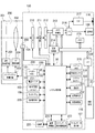
FIG. 2 is a diagram showing an example of the internal configuration of the
First, the
The
The
The
次に、カメラ100について説明する。
カメラ100は、シャッター210、撮像部211、A/D変換器212、メモリ制御部213、画像処理部214、メモリ215、D/A変換器216、EVF217、表示部108、システム制御部50を有する。
シャッター210は、システム制御部50の指示に基づいて撮像部211の露光時間を自由に制御できるフォーカルプレーンシャッターである。撮像部211は、光学像を電気信号に変換するCCDやCMOS素子等で構成される撮像素子(イメージセンサ)である。撮像部211は、システム制御部50にデフォーカス量情報を出力する撮像面位相差センサを有していてもよい。A/D変換器212は、撮像部211から出力されるアナログ信号をデジタル信号に変換する。画像処理部214は、A/D変換器212からのデータまたはメモリ制御部213からのデータに対し所定の処理(画素補間、縮小等のリサイズ処理、色変換処理等)を行う。また、画像処理部214は、撮影した画像データを用いて所定の演算処理を行い、得られた演算結果に基づいてシステム制御部50が露光制御や測距制御を行う。この処理により、TTL(スルー・ザ・レンズ)方式のAF処理、AE(自動露出)処理、EF(フラッシュプリ発光)処理等が行われる。更に、画像処理部214は、撮影した画像データを用いて所定の演算処理を行い、得られた演算結果に基づいてTTL方式のAWB(オートホワイトバランス)処理を行う。
Next, the
The
The
A/D変換器212からの画像データは、画像処理部214およびメモリ制御部213を介してメモリ215に書き込まれる。あるいは、A/D変換器212からの画像データは、画像処理部214を介さずにメモリ制御部213を介してメモリ215に書き込まれる。メモリ215は、撮像部211によって得られA/D変換器212によりデジタルデータに変換された画像データや、表示部108やEVF217に表示するための画像データを格納する。メモリ215は、所定枚数の静止画像や所定時間の動画像および音声を格納するのに十分な記憶容量を備えている。また、メモリ215は画像表示用のメモリ(ビデオメモリ)を兼ねている。
The image data from the A /
D/A変換器216は、メモリ215に格納されている画像表示用のデータをアナログ信号に変換して表示部108やEVF217に供給する。したがって、メモリ215に書き込まれた表示用の画像データは、D/A変換器216を介して表示部108やEVF217に表示される。表示部108やEVF217は、D/A変換器216からのアナログ信号に応じた表示を行う。表示部108やEVF217は、例えば、LCDや有機EL等のディスプレイである。A/D変換器212によってA/D変換されメモリ215に蓄積されたデジタル信号をD/A変換器216でアナログ信号に変換し、表示部108やEVF217に逐次転送して表示することで、ライブビュー表示が行われる。
The D /
システム制御部50は、少なくとも1つのプロセッサおよび/または少なくとも1つの回路からなる制御部である。すなわち、システム制御部50は、プロセッサであってもよく、回路であってもよく、プロセッサと回路の組み合わせであってもよい。システム制御部50は、カメラ100全体を制御する。システム制御部50は、不揮発性メモリ219に記録されたプログラムを実行することで、後述するフローチャートの各処理を実現する。また、システム制御部50は、メモリ215、D/A変換器216、表示部108、EVF217等を制御することにより表示制御も行う。
The
また、カメラ100は、システムメモリ218、不揮発性メモリ219、システムタイマ220、通信部221、姿勢検知部222、接眼検知部118を有する。
システムメモリ218は、例えばRAMが用いられる。システムメモリ218には、システム制御部50の動作用の定数、変数、不揮発性メモリ219から読み出したプログラム等が展開される。不揮発性メモリ219は、電気的に消去・記録可能なメモリであり、例えばEEPROMが用いられる。不揮発性メモリ219には、システム制御部50の動作用の定数、プログラム等が記録される。ここでのプログラムとは、後述するフローチャートを実行するためのプログラムである。システムタイマ220は、各種制御に用いる時間や、内蔵された時計の時間を計測する計時部である。通信部221は、無線または有線ケーブルによって接続された外部機器との間で、映像信号や音声信号の送受信を行う。通信部221は無線LAN(Local Area Network)やインターネットとも接続可能である。また、通信部221は、Bluetooth(登録商標)やBluetooth Low Energyでも外部機器と通信可能である。通信部221は撮像部211で撮影した画像(ライブ画像を含む)や、記録媒体227に記録された画像を送信可能であり、外部機器から画像データやその他の各種情報を受信することができる。姿勢検知部222は、重力方向に対するカメラ100の姿勢を検知する。姿勢検知部222で検知された姿勢に基づいて、撮像部211で撮影された画像が、カメラ100を横に構えて撮影された画像であるか、縦に構えて撮影された画像であるかを判別可能である。システム制御部50は、姿勢検知部222で検知された姿勢に応じた向き情報を撮像部211で撮影された画像の画像ファイルに付加したり、画像を回転して記録したりすることが可能である。姿勢検知部222は、例えば、加速度センサやジャイロセンサ等を用いることができる。姿勢検知部222を用いて、カメラ100の動き(パン、チルト、持ち上げ、静止しているか否か等)を検知することも可能である。
Further, the
For the
接眼検知部118は、EVF217を内蔵する接眼ファインダ117の接眼部116に対する何らかの物体の接近を検知することができる。接眼検知部118は、例えば、赤外線近接センサを用いることができる。物体が接近した場合、接眼検知部118の投光部から投光した赤外線が物体で反射して赤外線近接センサの受光部で受光される。受光された赤外線の量によって接眼部116から物体までの距離を判別することができる。このように、接眼検知部118は、接眼部116に対する物体の近接距離を検知する接眼検知を行う。接眼検知部118は、接眼ファインダ117の接眼部116に対する眼(物体)の接近(接眼)および離反(離眼)を検知する接眼検知センサである。非接眼状態(非接近状態)から、接眼部116に対して所定距離以内に近づく物体が検知された場合に、接眼されたと検知する。一方、接眼状態(接近状態)から、接近を検知していた物体が所定距離以上離れた場合に、離眼されたと検知する。接眼を検知する閾値と、離眼を検知する閾値は例えばヒステリシスを設ける等して異なっていてもよい。また、接眼を検知した後は、離眼を検知するまでは接眼状態であるものとする。離眼を検知した後は、接眼を検知するまでは非接眼状態であるものとする。システム制御部50は、接眼検知部118で検知された状態に応じて、表示部108とEVF217の表示(表示状態)/非表示(非表示状態)を切り替える。具体的には、少なくとも撮影待機状態であって、かつ、表示先の切替設定が自動切替である場合、非接眼中は表示先を表示部108として表示をオンとし、EVF217は非表示とする。また、接眼中は表示先をEVF217として表示をオンとし、表示部108は非表示とする。なお、接眼検知部118は、赤外線近接センサである場合に限られず、接眼とみなせる状態を検知できるものであれば他のセンサを用いてもよい。
The
また、カメラ100は、ファインダ外表示部107、ファインダ外表示駆動回路223、電源制御部224、電源部225、記録媒体I/F226、操作部228等を有する。
ファインダ外表示部107は、ファインダ外表示駆動回路223を介して、シャッター速度や絞り等のカメラ100の様々な設定値を表示する。電源制御部224は、電池検出回路、DC−DCコンバータ、通電するブロックを切り替えるスイッチ回路等により構成され、電池の装着の有無、電池の種類、電池残量の検出等を行う。また、電源制御部224は、その検出結果およびシステム制御部50の指示に基づいてDC−DCコンバータを制御し、必要な電圧を必要な期間、記録媒体227を含む各部へ供給する。電源部225は、アルカリ電池およびリチウム電池等の一次電池、NiCd電池、NiMH電池およびLi電池等の二次電池、ACアダプター等である。記録媒体I/F226は、メモリカードやハードディスク等の記録媒体227とのインターフェースである。記録媒体227は、撮影された画像を記録するためのメモリカード等であり、半導体メモリや磁気ディスク等から構成される。記録媒体227は、着脱可能であってもよく、内蔵されていてもよい。
Further, the
The out-of-
操作部228は、ユーザからの操作(ユーザ操作)を受け付ける入力部であり、システム制御部50に各種の指示を入力するために用いられる。操作部228は、シャッターボタン101、電源スイッチ102、モード切替スイッチ103、タッチパネル109、他の操作部229等が含まれる。他の操作部229には、メイン電子ダイヤル104、サブ電子ダイヤル105、動画ボタン106、方向キー110、SETボタン111、AEロックボタン112、拡大ボタン113、再生ボタン114、メニューボタン115、タッチバー119等が含まれる。
シャッターボタン101は、第1シャッタースイッチ230と第2シャッタースイッチ231を有する。第1シャッタースイッチ230は、シャッターボタン101の操作途中、いわゆる半押し(撮影準備指示)でオンとなり、第1シャッタースイッチ信号SW1を発生させる。システム制御部50は、第1シャッタースイッチ信号SW1により、AF処理、AE処理、AWB処理、EF処理等の撮影準備処理を開始する。第2シャッタースイッチ231は、シャッターボタン101の操作完了、いわゆる全押し(撮影指示)でオンとなり、第2シャッタースイッチ信号SW2を発生する。システム制御部50は、第2シャッタースイッチ信号SW2により、撮像部211からの信号読み出しから、撮影された画像を含む画像ファイルを生成して記録媒体227に書き込むまでの一連の撮影処理を開始する。
The
The
モード切替スイッチ103は、システム制御部50の動作モードを静止画撮影モード、動画撮影モード、再生モード等の何れかに切り替える。静止画撮影モードに含まれるモードには、オート撮影モード、オートシーン判別モード、マニュアルモード、絞り優先モード(Avモード)、シャッター速度優先モード(Tvモード)、プログラムAEモード(Pモード)がある。また、撮影シーン別の撮影設定となる各種シーンモード、カスタムモード等がある。ユーザは、モード切替スイッチ103により、上述した撮影モードの何れかに直接、切り替えることができる。あるいは、ユーザは、モード切替スイッチ103により撮影モードの一覧画面に一旦切り替えた後に、表示された複数のモードの何れかに操作部228を用いて選択的に切り替えることができる。同様に、動画撮影モードにも複数のモードが含まれていてもよい。
The
タッチパネル109は、表示部108の表示面(タッチパネル109の操作面)への各種タッチ操作を検出するタッチセンサである。タッチパネル109と表示部108とは一体的に構成することができる。例えば、タッチパネル109は、光の透過率が表示部108の表示を妨げないように、表示部108の表示面の上層に取り付けられる。そして、タッチパネル109における入力座標と、表示部108の表示面上の表示座標とを対応付けることで、あたかもユーザが表示部108上に表示された画面を直接的に操作可能であるかのようなGUI(グラフィカルユーザインターフェース)を構成できる。タッチパネル109には、抵抗膜方式や静電容量方式、表面弾性波方式、赤外線方式、電磁誘導方式、画像認識方式、光センサ方式等の様々な方式のうち何れかの方式を用いることができる。方式によって、タッチパネル109に対する接触があったことでタッチがあったと検知する方式や、タッチパネル109に対する指やペンの接近があったことでタッチがあったと検知する方式があるが、何れの方式であってもよい。
The
システム制御部50は、タッチパネル109に対する以下の操作あるいは状態を検出できる。
・タッチパネル109にタッチしていなかった指やペンが新たにタッチパネル109にタッチしたこと、すなわちタッチの開始(以下、タッチダウン(Touch−Down)という)。
・タッチパネル109を指やペンでタッチしている状態(以下、タッチオン(Touch−On)という)。
・タッチパネル109を指やペンがタッチしたまま移動していること(以下、タッチムーブ(Touch−Move)という)。
・タッチパネル109へタッチしていた指やペンがタッチパネル109から離れた(リリースされた)こと、すなわちタッチの終了(以下、タッチアップ(Touch−Up)という)。
・タッチパネル109に何もタッチしていない状態(以下、タッチオフ(Touch−Off)という)。
The
-A finger or pen that has not touched the
-A state in which the
-The
-The finger or pen touching the
-A state in which nothing is touched on the touch panel 109 (hereinafter referred to as touch-off).
タッチダウンが検出されると、同時にタッチオンも検出される。タッチダウンの後、タッチアップが検出されない限りは、通常はタッチオンが検出され続ける。タッチムーブが検出された場合も、同時にタッチオンが検出される。タッチオンが検出されていても、タッチ位置が移動していなければタッチムーブは検出されない。タッチしていた全ての指やペンがタッチアップしたことが検出された後は、タッチオフとなる。 When touchdown is detected, touch-on is also detected at the same time. After touchdown, touch-on usually continues to be detected unless touch-up is detected. When a touch move is detected, a touch-on is detected at the same time. Even if touch-on is detected, touch move is not detected unless the touch position is moved. After it is detected that all the fingers and pens that have been touched are touched up, the touch is turned off.
これらの操作・状態や、タッチパネル109上に指やペンがタッチしている位置座標は内部バスを通じてシステム制御部50に通知される。システム制御部50は通知された情報に基づいてタッチパネル109上にどのような操作(タッチ操作)が行なわれたかを判定する。タッチムーブについてはタッチパネル109上で移動する指やペンの移動方向についても、位置座標の変化に基づいて、タッチパネル109上の垂直成分・水平成分毎に判定できる。所定距離以上をタッチムーブしたことが検出された場合はスライド操作が行なわれたと判定される。タッチパネル109上に指をタッチしたままある程度の距離だけ素早く動かして、そのまま離すといった操作をフリックという。フリックは、言い換えればタッチパネル109上を指ではじくように素早くなぞる操作である。所定距離以上を、所定速度以上でタッチムーブしたことが検出され、そのままタッチアップが検出されるとフリックが行なわれたと判定される(スライド操作に続いてフリックがあったものと判定できる)。更に、複数箇所(例えば2点)を共にタッチして(マルチタッチして)、互いのタッチ位置を近づけるタッチ操作をピンチイン、互いのタッチ位置を遠ざけるタッチ操作をピンチアウトという。ピンチアウトとピンチインを総称してピンチ操作(あるいは単にピンチ)という。
These operations / states and the position coordinates of the finger or pen touching the
図3は、レンズユニット300の構成の一例を示す模式図である。図3では、レンズユニット300をカメラ100に装着した状態を示している。なお、図3に示すカメラ100のうち図2で説明した構成と同一の構成は、同一符号を付して適宜、説明を省略する。
FIG. 3 is a schematic view showing an example of the configuration of the
レンズユニット300は、カメラ100に着脱可能な交換レンズの一種である。レンズユニット300は、左像および右像で視差がある撮影が可能な2眼レンズである。レンズユニット300は、2つの光学系を有し、それぞれ略180度の広視野角であって、前方半球の範囲を撮影できる。具体的に、レンズユニット300の2つの光学系は、それぞれ左右方向(水平角度、方位角、ヨー角)180度、上下方向(垂直角度、仰俯角、ピッチ角)180度の視野分(画角分)の被写体を撮影できる。
The
レンズユニット300は、複数のレンズと反射ミラー等を有する右眼光学系301R、複数のレンズと反射ミラー等を有する左眼光学系301L、レンズシステム制御回路303を有する。右眼光学系301Rは第1の光学系の一例に対応し、左眼光学系301Lは第2の光学系の一例に対応する。右眼光学系301Rおよび左眼光学系301Lはそれぞれ被写体側に位置する各レンズ302R、302Lが同じ方向を向いており、各光軸が略平行である。本実施形態のレンズユニット300は、2眼立体視が可能なVR画像のフォーマットであるいわゆるVR180のための画像を撮影するためのVR180用レンズである。VR180用レンズは、右眼光学系301Rおよび左眼光学系301Lがそれぞれ略180度の範囲を捉えることが可能な魚眼レンズを有する。なお、VR180用レンズは、右眼光学系301Rおよび左眼光学系301LがそれぞれVR180としての2眼VR表示が可能な映像が取得できればよく、180度の範囲よりも狭い160度程度の広視野角の範囲を捉えることが可能なレンズであってもよい。VR180用レンズは、右眼光学系301Rを介して形成される右像(第一像)と、右像とは視差を有する左眼光学系301Lを介して形成される左像(第二像)とを、装着したカメラの1つまたは2つの撮像素子上に形成することができる。
また、レンズユニット300は、レンズマウント部304と、カメラ100のカメラマウント部305とを介して、カメラ100に装着される。レンズユニット300がカメラ100に装着されることで、カメラ100の通信端子124と、レンズユニット300の通信端子306とを介して、カメラ100のシステム制御部50とレンズユニット300のレンズシステム制御回路303とが電気的に接続される。
The
Further, the
本実施形態では、右眼光学系301Rを介して形成される右像と、右像とは視差を有する左眼光学系301Lを介して形成される左像とは、並んでカメラ100の撮像部211に結像される。すなわち、右眼光学系301Rおよび左眼光学系301Lにより形成される2つの光学像が1つの撮像素子上に形成される。撮像部211は、結像された被写体像(光信号)をアナログ電気信号に変換する。このように、レンズユニット300を用いることで、右眼光学系301Rと左眼光学系301Lとの2つの箇所(光学系)から視差がある2つの画像を同時に(セットで)取得することができる。また、取得された画像を左眼用の画像と右眼用の画像とに分けてVR表示することで、ユーザは略180度の範囲の立体的なVR画像、いわゆるVR180を視聴することができる。
In the present embodiment, the right image formed via the right eye
ここで、VR画像とは、後述するVR表示することができる画像である。VR画像には、全方位カメラ(全天球カメラ)で撮影した全方位画像(全天球画像)や、表示部に一度で表示できる表示範囲より広い映像範囲(有効映像範囲)を持つパノラマ画像等が含まれる。また、VR画像は、静止画に限られず、動画、ライブ画像(カメラからほぼリアルタイムで取得した画像)も含まれる。VR画像は、最大で、左右方向360度、上下方向360度の視野分の映像範囲(有効映像範囲)を持つ。また、VR画像には、左右方向360度未満、上下方向360度未満であっても、通常のカメラで撮影可能な画角よりも広範な画角、あるいは、表示部に一度で表示できる表示範囲より広い映像範囲を持つ画像も含まれる。上述したレンズユニット300を用いてカメラ100で撮影される画像は、VR画像の一種である。VR画像は、例えば、表示装置(VR画像を表示できる表示装置)の表示モードを「VRビュー」に設定することでVR表示することができる。360度の画角を有するVR画像をVR表示させて、ユーザが表示装置の姿勢を左右方向(水平回転方向)に変化させることで、左右方向に継ぎ目のない全方位の映像を観賞することができる。
Here, the VR image is an image that can be displayed in VR, which will be described later. VR images include omnidirectional images (omnidirectional images) taken with an omnidirectional camera (omnidirectional camera) and panoramic images having a wider image range (effective image range) than the display range that can be displayed at once on the display unit. Etc. are included. Further, the VR image is not limited to a still image, but also includes a moving image and a live image (an image acquired from a camera in almost real time). The VR image has a maximum image range (effective image range) of 360 degrees in the horizontal direction and 360 degrees in the vertical direction. Further, the VR image has a wider angle of view than the angle of view that can be taken by a normal camera, or a display range that can be displayed on the display unit at once even if the angle is less than 360 degrees in the horizontal direction and less than 360 degrees in the vertical direction. Images with a wider video range are also included. The image taken by the
ここで、VR表示(VRビュー)とは、VR画像のうち、表示装置の姿勢に応じた視野範囲の映像を表示する、表示範囲を変更可能な表示方法(表示モード)である。VR表示には、VR画像を仮想球体にマッピングする変形(歪曲補正が施される変形)を行って1つの画像を表示する「1眼VR表示(1眼VRビュー)」がある。また、VR表示には、左眼用のVR画像と右眼用のVR画像とをそれぞれ仮想球体にマッピングする変形を行って左右の領域に並べて表示する「2眼VR表示(2眼VRビュー)」がある。互いに視差のある左眼用のVR画像と右眼用のVR画像を用いて「2眼VR表示」を行うことで立体視することが可能である。何れのVR表示であっても、例えば、ユーザがHMD(ヘッドマウントディスプレイ)等の表示装置を装着した場合、ユーザの顔の向きに応じた視野範囲の映像が表示される。例えば、VR画像のうち、ある時点で左右方向に0度(特定の方位、例えば北)、上下方向に90度(天頂から90度、すなわち水平)を中心とした視野範囲の映像を表示しているとする。この状態から表示装置の姿勢を表裏反転させる(例えば、表示面を南向きから北向きに変更する)と、同じVR画像のうち、左右方向に180度(逆の方位、例えば南)、上下方向に90度を中心とした視野範囲の映像に、表示範囲が変更される。すなわち、ユーザがHMDを装着した状態で、顔を北から南に向く(すなわち後ろを向く)ことで、HMDに表示される映像も北の映像から南の映像に変更される。なお、本実施形態のレンズユニット300を用いて撮影したVR画像は、前方略180度の範囲を撮影したVR180の画像であり、後方略180度の範囲の映像は存在しない。このようなVR180の画像をVR表示させて、映像が存在しない側に表示装置の姿勢を変更した場合にはブランク領域が表示される。
Here, the VR display (VR view) is a display method (display mode) in which the display range can be changed, which displays an image of the viewing range according to the posture of the display device among the VR images. The VR display includes a "single-eye VR display (single-eye VR view)" that displays one image by performing a deformation (deformation in which distortion correction is applied) that maps a VR image to a virtual sphere. Further, in the VR display, the VR image for the left eye and the VR image for the right eye are each modified to be mapped to a virtual sphere and displayed side by side in the left and right areas. There is. Stereoscopic viewing is possible by performing "two-eye VR display" using a VR image for the left eye and a VR image for the right eye, which have parallax with each other. In any VR display, for example, when a user wears a display device such as an HMD (head-mounted display), an image in a visual field range corresponding to the orientation of the user's face is displayed. For example, in a VR image, at a certain point in time, an image having a viewing range centered on 0 degrees in the left-right direction (a specific direction, for example, north) and 90 degrees in the up-down direction (90 degrees from the zenith, that is, horizontal) is displayed. Suppose you are. When the posture of the display device is turned upside down from this state (for example, the display surface is changed from south to north), 180 degrees in the left-right direction (opposite direction, for example, south) and up-down direction in the same VR image. The display range is changed to an image with a viewing range centered on 90 degrees. That is, when the user turns his face from north to south (that is, faces backward) while wearing the HMD, the image displayed on the HMD is also changed from the north image to the south image. The VR image taken by using the
このようにVR画像をVR表示することによって、ユーザは視覚的にあたかもVR画像内(VR空間内)にいるような感覚になる。なお、VR画像の表示方法は表示装置の姿勢を変更する方法に限られない。例えば、タッチパネルや方向ボタン等を介したユーザ操作に応じて、表示範囲を移動(スクロール)させてもよい。また、VR表示時(表示モード「VRビュー」時)において、姿勢変化による表示範囲の変更に加え、タッチパネルでのタッチムーブ、マウス等でのドラッグ操作、方向ボタンの押下等に応じて表示範囲を変更してもよい。なお、VRゴーグル(ヘッドマウントアダプタ)に装着されたスマートフォンはHMDの一種である。 By displaying the VR image in VR in this way, the user visually feels as if he / she is in the VR image (in the VR space). The VR image display method is not limited to the method of changing the posture of the display device. For example, the display range may be moved (scrolled) according to a user operation via a touch panel, a direction button, or the like. In addition, in VR display (when the display mode is "VR view"), in addition to changing the display range by changing the posture, the display range is changed according to touch move on the touch panel, drag operation with the mouse, etc., pressing of the direction button, etc. You may change it. A smartphone attached to VR goggles (head mount adapter) is a type of HMD.
上述したように構成されるカメラ100おいてレンズユニット300を介して撮影される画像は、右眼光学系および左眼光学系を介してそれぞれ撮影されるために2つに分かれると共に、それぞれ広視野角の画像であるために歪みが生じている。したがって、レンズユニット300を介して撮影されるライブ画像を表示部108にライブビュー表示しても、ユーザは被写体の状況を確認しにくい場合がある。本実施形態では、広視野角の画像を2眼で撮影するのに適したライブビュー表示するカメラ100の処理について図4のフローチャートを参照して説明する。
The image taken through the
図4は、カメラ100の処理の一例を示すフローチャートである。図4のフローチャートは、システム制御部50が不揮発性メモリ219に記録されたプログラムをシステムメモリ218に展開して実行することにより実現する。また、図4のフローチャートは、撮影モードが静止画撮影モードに設定されることで開始される。
FIG. 4 is a flowchart showing an example of processing of the
S401では、システム制御部50は、装着されたレンズユニットの種類の情報を取得して、レンズユニットが2眼レンズであるか否か、ここではVR180用レンズであるか否かを判定する。具体的には、システム制御部50は、装着されたレンズユニットと通信端子124、206、306を介して通信することでレンズユニットからレンズユニットの種類の情報を取得することができる。装着されたレンズユニットがVR180用レンズである場合にはS408に進む。一方、例えば、レンズユニットが非装着、あるいは装着されたレンズユニットが1眼レンズ等の通常のレンズユニットであり、VR180用レンズではない場合にはS402に進む。
In S401, the
S402では、システム制御部50は、レンズユニット(例えば、1眼レンズ等の通常のレンズユニット)を介して撮像部211により撮影されているライブ画像を表示部108に表示するライブビュー表示を行うことで、ライブビュー画像を表示する。ここで、ライブビュー画像とは、ライブ画像を表示部108にライブビュー表示した画像をいう。
図5は、表示部108に表示されたライブビュー画像500の一例を示す図である。
図5に示すライブビュー画像500は、表示部108の表示画面の全面に亘って表示される。ユーザは表示部108に表示されたライブビュー画像500を視認することで、所望する撮影ができるかを確認することができる。
In S402, the
FIG. 5 is a diagram showing an example of the
The
S403では、システム制御部50は、ライブビュー表示中にシャッターボタン101が半押しされ、第1シャッタースイッチ230がオンになったか否かを判定する。具体的に、システム制御部50は第1シャッタースイッチ信号SW1を受信したか否かを判定する。第1シャッタースイッチ230がオンになった場合、すなわち第1シャッタースイッチ信号SW1を受信した場合にはS404に進む。一方、第1シャッタースイッチ230がオンではない場合、すなわち第1シャッタースイッチ信号SW1を受信していない場合にはS405に進む。
S404では、システム制御部50は撮影準備処理を行う。具体的には、システム制御部50は、AF処理、AE処理、AWB処理、EF処理等を開始する。
In S403, the
In S404, the
S405では、システム制御部50は、ライブビュー表示中にシャッターボタン101が全押しされ、第2シャッタースイッチ231がオンになったか否かを判定する。具体的に、システム制御部50は第2シャッタースイッチ信号SW2を受信したか否かを判定する。第2シャッタースイッチ231がオンになった場合、すなわち第2シャッタースイッチ信号SW2を受信した場合にはS406に進む。一方、第2シャッタースイッチ231がオンではない場合、すなわち第2シャッタースイッチ信号SW2を受信していない場合にはS401に戻る。
S406では、システム制御部50は撮影処理を行う。具体的には、システム制御部50は、撮像部211からの信号読み出しから、撮影された画像を含む画像ファイルを生成して記録媒体227に書き込むまでの一連の撮影処理を行う。ここで記録される画像ファイルのファイル名は例えば“IMG_3456.jpg”といったDCF規格に則ったファイル名となる。また、後述するS418で記録されるVR180用の画像ファイルの画像のように、左眼映像範囲801Lや右眼映像範囲801Rの抽出(取得)や、VR180用の変形処理(円筒図法を用いた変形)などは行われない。
In S405, the
In S406, the
S407では、システム制御部50は、撮影指示に応じて撮像部211により撮影された画像をクイックレビュー表示する。クイックレビュー表示とは、撮影指示に応じて画像が撮影された直後に、ユーザが撮影された画像を確認するために表示する処理をいう。ただし、メニュー等によるクイックレビュー表示をしないように設定されている場合にはS407を省略することができる。その後、システム制御部50はS401に戻り、再びレンズユニットがVR180用レンズであるか否かを判定する。
In S407, the
S408では、システム制御部50は、ライブビュー表示するときの表示モードが第1の表示モードであるか否かを判定する。具体的に、システム制御部50は、不揮発性メモリ219に記憶された制御変数に、第1の表示モードの情報が記憶されているか否かを判定する。第1の表示モードの情報が記憶されている場合にはS409に進み、第1の表示モードの情報が記憶されていない場合にはS410に進む。
ここで、本実施形態では、VR180用レンズが装着されている場合に、VR180用レンズを介して撮影されているライブ画像をライブビュー表示させるときの表示モードをユーザが予め設定することができる。
In S408, the
Here, in the present embodiment, when the VR180 lens is attached, the user can set in advance the display mode for displaying the live image taken through the VR180 lens in the live view.
図6は、表示モード設定画面600の一例を示す図である。
表示モード設定画面600は、例えば、メニューボタン115を押下することで表示されるメニュー画面のうち所定の表示モード設定項目を選択することにより表示部108に表示される。
表示モード設定画面600には、第1の表示モード選択ボタン601〜第4の表示モード選択ボタン604が選択可能に表示される。ユーザは第1の表示モード選択ボタン601〜第4の表示モード選択ボタン604のうち、所望する表示モードに対応する選択ボタンを方向キー110でカーソル605を移動させた上でSETボタン111を押下することで選択する。あるいは、ユーザは第1の表示モード選択ボタン601〜第4の表示モード選択ボタン604のうち、所望する表示モードに対応する選択ボタンを直接、タッチして選択する。システム制御部50は、ユーザ操作により選択された選択ボタンに対応する表示モードの情報を制御変数に代入して、例えば不揮発性メモリ219に記憶することで表示モードを設定する。なお、表示モード選択画面600を表示させずとも、第1〜第4の表示モードのいずれかで表示を行っている際に、他の操作部229に含まれる表示モード切替ボタンが押下されるたびに表示モードを順次切り替えて設定する(トグルする)ようにしても良い。なお、第1の表示モード選択ボタン601〜第4の表示モード選択ボタン604に対応する各表示モードについては、図7を参照して後述する。
FIG. 6 is a diagram showing an example of the display
The display
On the display
S409では、システム制御部50は、VR180用レンズを介して撮像部211により撮影されているライブ画像を第1の表示モードで表示部108に表示するライブビュー表示を行う。第1の表示モードは、撮像部211が撮影しているライブ画像を、後述する円筒図法に基づいた変形をせずに表示部108にライブビュー表示させるモードである。本実施形態の第1の表示モードでは、撮像部211により撮影しているライブ画像をそのまま表示部108に表示させる。
In S409, the
図7(a)は、第1の表示モードでライブビュー表示されたライブビュー画像700の一例を示す図である。ライブビュー画像700には、右眼光学系301Rを介して撮影されたライブ画像に対応するライブビュー画像701Rと、左眼光学系301Lを介して撮影されたライブ画像に対応するライブビュー画像701Lとが含まれる。また、各ライブビュー画像701R、701Lに注目すると、それぞれ円形であり、円形の外縁に近づくほど大きく歪んでいる。
第1の表示モードは、ライブ画像を変形させずにライブビュー表示することから画像処理を軽減できるために比較的、容易に実現することができる。また、2つの光学系で2つの広視野画像が撮影されていることがわかり、VR180用レンズが装着されて撮影指定状態であることが認識しやすい。一方、第1の表示モードは、1つの画面に2つの画像が分かれて表示され、かつ大きく歪んでいるために、ユーザがピントや被写体の表情等を細かく確認するのには適していない。したがって、ユーザは、例えば、ピントや被写体の表情等を細かく確認する必要がない場合等に第1の表示モードを選択する。
FIG. 7A is a diagram showing an example of the
The first display mode can be realized relatively easily because the image processing can be reduced because the live view is displayed without deforming the live image. Further, it can be seen that two wide-field images are taken by the two optical systems, and it is easy to recognize that the VR180 lens is attached and the shooting is specified. On the other hand, the first display mode is not suitable for the user to check the focus, the facial expression of the subject, and the like in detail because the two images are displayed separately on one screen and are greatly distorted. Therefore, the user selects the first display mode, for example, when it is not necessary to check the focus, the facial expression of the subject, or the like in detail.
次に、S410では、システム制御部50は、ライブビュー表示するときの表示モードが第2の表示モードであるか否かを判定する。具体的に、システム制御部50は、不揮発性メモリ219に記憶された制御変数に、第2の表示モードの情報が記憶されているか否かを判定する。第2の表示モードの情報が記憶されている場合にはS411に進み、第2の表示モードの情報が記憶されていない場合にはS412に進む。
Next, in S410, the
S411では、システム制御部50は、VR180用レンズを介して撮像部211により撮影されているライブ画像を第2の表示モードで表示部108に表示するライブビュー表示を行う。第2の表示モードは、右眼光学系を介して撮影されるライブ画像と、左眼光学系を介して撮影されるライブ画像とをそれぞれ円筒図法に基づいて変形させて両方を表示部108にライブビュー表示させるモードである。具体的には、システム制御部50はライブ画像に対する画像処理を画像処理部214に行わせる。画像処理部214は、撮像部211により撮影されているライブ画像のうち、右眼光学系を介して撮影されるライブ画像に対応する領域(第1の所定の領域)を切り出し、左眼光学系を介して撮影されるライブ画像に対応する領域(第2の所定の領域)を切り出す。画像処理部214は、切り出した各ライブ画像をそれぞれ円筒図法に基づいて変換することで変形させる。
In S411, the
図7(b)は、第2の表示モードでライブビュー表示されたライブビュー画像702の一例を示す図である。ライブビュー画像702には、右眼光学系を介して撮影されたライブ画像を円筒図法に基づいて変形させたライブビュー画像703Rと、左眼光学系を介して撮影されたライブ画像を円筒図法に基づいて変形させたライブビュー画像703Lとが含まれる。また、ライブビュー画像703Rとライブビュー画像703Lとのそれぞれに注目すると、外縁の歪みが抑制されている。
FIG. 7B is a diagram showing an example of the
円筒図法は、球に接触する円筒面上に球表面上の画像を射影させる図法をいう。本実施形態では、円筒図法として、例えば、緯線・経線が直角かつ等間隔に交差する正距円筒図法を用いる。VR180用レンズのうち、右眼光学系を介して撮影されたライブ画像と、左眼光学系を介して撮影されたライブ画像とは、それぞれ略半球状のライブ画像とみなすことができる。略半球状のライブ画像を円筒図法に基づいて変形させることで、それぞれ矩形状で外縁の歪みが抑制されたライブ画像に変換される。 The cylindrical projection is a projection in which an image on the surface of a sphere is projected onto a cylindrical surface in contact with the sphere. In this embodiment, as the cylindrical projection, for example, an equirectangular projection in which parallels and meridians intersect at right angles and at equal intervals is used. Among the lenses for VR180, the live image taken through the right eye optical system and the live image taken through the left eye optical system can be regarded as substantially hemispherical live images, respectively. By deforming a substantially hemispherical live image based on a cylindrical projection, each is converted into a rectangular live image in which distortion of the outer edge is suppressed.
このように、第2の表示モードは、ライブ画像を円筒図法に基づいて変形させてライブビュー表示することから、外縁の歪みが抑制されるために、ユーザは写り具合を確認することができる。一方、第2の表示モードは、1つの画面に2つの画像が分かれて表示されるために、ピントや被写体の表情等を細かく確認するのには適さない。したがって、ユーザは、例えば、ピントや被写体の表情等を細かく確認する必要がないものの、被写体の状況を大まかに把握したい場合等に第2の表示モードを選択する。 As described above, in the second display mode, since the live image is deformed based on the cylindrical projection and displayed in the live view, the distortion of the outer edge is suppressed, so that the user can check the image quality. On the other hand, the second display mode is not suitable for checking the focus, the facial expression of the subject, and the like in detail because the two images are displayed separately on one screen. Therefore, for example, the user does not need to check the focus, the facial expression of the subject, and the like in detail, but selects the second display mode when he / she wants to roughly grasp the situation of the subject.
次に、S412では、システム制御部50は、ライブビュー表示するときの表示モードが第3の表示モードであるか否かを判定する。具体的に、システム制御部50は、不揮発性メモリ219に記憶された制御変数に、第3の表示モードの情報が記憶されているか否かを判定する。第3の表示モードの情報が記憶されている場合にはS413に進む。一方、第3の表示モードの情報が記憶されていない場合には第4の表示モードの情報が記憶されておりS414に進む。
Next, in S412, the
S413では、システム制御部50は、VR180用レンズを介して撮像部211により撮影されているライブ画像を第3の表示モードで表示部108に表示するライブビュー表示を行う。第3の表示モードは、右眼光学系を介して撮影されるライブ画像と、左眼光学系を介して撮影されるライブ画像とのうち一方のライブ画像を円筒図法に基づいて変形させ、変形させた画像を表示部108の中央側に寄せてライブビュー表示させるモードである。システム制御部50はライブ画像に対する画像処理を画像処理部214に行わせる。画像処理部214は、撮像部211により撮影されているライブ画像のうち、例えば右眼光学系を介して撮影されるライブ画像に対応する領域を切り出し、切り出したライブ画像を円筒図法に基づいて変換することで変形させる。
In S413, the
図7(c)は、第3の表示モードでライブビュー表示されたライブビュー画像704の一例を示す図である。ライブビュー画像704は、例えば右眼光学系を介して撮影されたライブ画像を円筒図法に基づいて変形させた画像であり、表示画面の中央寄りに表示されている。また、ライブビュー画像704は、図7(b)に示すライブビュー画像703Rよりも拡大して表示される。なお、ライブビュー画像704は、右眼光学系を介して撮影されたライブ画像を変形させる場合に限られず、左眼光学系を介して撮影されたライブ画像を変形させた画像であってもよい。
また、ライブビュー画像704を、右眼光学系を介して撮影されたライブ画像を変形させた画像にするか、左眼光学系を介して撮影されたライブ画像を変形させた画像にするかを、ユーザが選択できるようにしてもよい。この場合、例えば、図6に示す表示モード設定画面600において、第3の表示モード選択ボタン603を選択した後に、更に右眼光学系または左眼光学系を介して撮影されたライブ画像を変形させるかを選択させることで実現することができる。
FIG. 7C is a diagram showing an example of the
Further, whether the
このように、第3の表示モードは、ライブ画像を円筒図法に基づいて変形させてライブビュー表示することから、外縁の歪みが抑制される上、1つの画面に1つの画像のみが表示される。このため、ユーザはピントや被写体の表情等を細かく確認することができ、通常のレンズで撮影する場合と同じ感覚で撮影することができる。したがって、ユーザは、例えば、被写体の状況を細かく確認したい場合等に第3の表示モードを選択する。 As described above, in the third display mode, since the live image is deformed based on the cylindrical projection and displayed in the live view, the distortion of the outer edge is suppressed and only one image is displayed on one screen. .. Therefore, the user can check the focus, the facial expression of the subject, and the like in detail, and can shoot with the same feeling as when shooting with a normal lens. Therefore, the user selects the third display mode, for example, when he / she wants to check the situation of the subject in detail.
次に、S414では、システム制御部50は、第4の表示モードとして、VR180用レンズを介して撮像部211により撮影されているライブ画像を表示部108に表示させない。すなわち、第4の表示モードは、ライブビュー画像を表示しないモードである。
Next, in S414, the
図7(d)は、第4の表示モードでの表示例を示す図である。ここでは、ライブビュー画像が表示されず、VR180用レンズを介してライブ画像を撮影していることを示す情報705が表示される。このようにライブビュー画像を表示しないのは、広視野角の画像では、全体に対して写る主被写体が小さいために表情等を確認できないおそれがあるためである。また、広視野角の画像は、撮影範囲が非常に広いために、ユーザはおおよその位置でシャッターボタン101を押しても、少なくとも主被写体を撮影することが可能である。
このように、第4の表示モードは、ライブビュー画像を表示しないことで直接、肉眼で被写体を視認して撮影することをユーザに対して促すことができる。ただし、ユーザが接眼部116に接眼して接眼ファインダ117を覗いている場合には、EVF217に何も表示されないと、そもそも肉眼による視認もできない。したがって、システム制御部50は、第4の表示モードの情報が記憶されていても、接眼検知部118が物体の接近を検知している場合には、EVF217に第4の表示モード以外である第1〜第3の表示モードの何れかのモードでライブビュー表示してもよい。
FIG. 7D is a diagram showing a display example in the fourth display mode. Here, the live view image is not displayed, and the
As described above, the fourth display mode can prompt the user to directly visually recognize and shoot the subject with the naked eye by not displaying the live view image. However, when the user looks into the
次に、S415では、システム制御部50は、ライブビュー表示中にシャッターボタン101が半押しされ、第1シャッタースイッチ230がオンになったか否かを判定する。この処理は、S403と同様の処理である。第1シャッタースイッチ230がオンになった場合にはS416に進む。一方、第1シャッタースイッチ230がオンではない場合にはS417に進む。
S416では、システム制御部50は撮影準備処理を行う。この処理は、S404と同様の処理である。
Next, in S415, the
In S416, the
S417では、システム制御部50は、ライブビュー表示中にシャッターボタン101が全押しされ、第2シャッタースイッチ231がオンになったか否かを判定する。この処理は、S405と同様の処理である。第2シャッタースイッチ231がオンになった場合にはS418に進む。一方、第2シャッタースイッチ231がオンではない場合にはS401に戻る。
S418では、システム制御部50は撮影処理を行う。具体的には、システム制御部50は撮像部211からの信号読み出しから、右眼光学系を介して撮影された画像と左眼光学系を介して撮影された画像とを含む画像ファイルを生成して記録媒体227に書き込むまでの一連の撮影処理を行う。また、システム制御部50は、VR180のファイルフォーマットに基づいた画像データに変換して記録する。ここでは、動画モードであれば動画が、静止画モードであれば静止画が記録されるものとする。
In S417, the
In S418, the
S418の撮影処理において撮像部211で撮影される画像は、図8(a)に示す画像801のような画像である。画像801には、左目光学系を介して撮像部211に結像した左眼映像範囲801Lと、右眼光学系を介して撮像部211に結像した右眼映像範囲801Rが含まれる。黒塗りの部分も画像として撮影された部分であるが、左眼光学系と右眼光学系とのいずれも介さない暗部が撮影されたものとなる。左眼映像範囲801Lと右眼映像範囲801Rに写っている被写体像には互いに視差がある。
The image captured by the
S418の撮影処理において記録媒体227に記録される静止画は、図8(b)に示す画像802Lと画像802Rとなる。システム制御部50は、画像処理部214を用いて、撮影された画像801のうち、左眼映像範囲801Lを切り出して(トリミングして)、ほぼ正方形内に円筒図法で描画された画像802Lを記録する。また、システム制御部50は、画像処理部214を用いて、撮影された画像801のうち、右眼映像範囲801Rを切り出して(トリミングして)、ほぼ正方形内に円筒図法で描画された画像802Rを記録する。すなわち、撮影された画像801から左眼映像範囲801Lと右眼映像範囲801Rの抽出(取得)が行われる。この画像802Lと画像802Rは同じ静止画ファイル内にマルチピクチャーフォーマットで記録される。静止画のVR画像のファイル名は、S406で説明したVR180用ではない通常の画像ファイルとは区別できるように、例えば“123456.vr.jpg”となり、拡張子“.jpg”の手前に3文字の文字列“.vr”が記述される。このように静止画ファイルとして保存された画像を、VR表示が可能な機器で2眼VR表示すると、半球にマッピングされた立体視可能な静止画が表示される。
The still images recorded on the
また、S418の撮影処理において記録媒体227に記録される動画は、図8(c)に示す画像803となる。システム制御部50は、画像処理部214を用いて、撮影された画像801のうち、左眼映像範囲801Lと右眼映像範囲801Rをそれぞれ映像(動画)が1つの動画の映像内の左右に(サイドバイサイドで)並べられた動画ファイルを生成して記録する。動画のVR画像のファイル名は、S406で説明したVR180用ではない通常の画像ファイルとは区別できるように、例えば"123456.vr.mp4"となり、拡張子".mp4"の手前に3文字の文字列".vr"が記述される。このように動画ファイルとして保存された画像を、VR表示が可能な機器で2眼VR表示すると、半球にマッピングされた立体視可能な動画が表示される。
Further, the moving image recorded on the
このように、撮影処理によって記録される画像は、交換レンズとして通常の(VR180用レンズではない)レンズが装着されていたか、VR180用レンズが装着されていたかに応じて(すなわちS401の判定結果に応じて)変わる。すなわち、S406の処理を行って記録するか、S418の処理を行って記録するかが、VR180用レンズが装着されていた否かに応じて変わる。
なお、カメラ100内で記録する画像は、図8(b)、図8(c)で説明したものに限られず、図8(a)で説明した画像801の状態で(すなわち、トリミングや変形を施していない撮影画像を)画像ファイルとして記録媒体227に記録するものとしてもよい。
In this way, the image recorded by the photographing process is based on whether a normal lens (not a VR180 lens) is attached as an interchangeable lens or a VR180 lens is attached (that is, the determination result of S401). (Depending on) changes. That is, whether the processing of S406 is performed and the recording is performed or the processing of S418 is performed and the recording is performed depends on whether or not the VR180 lens is attached.
The image recorded in the
S419では、システム制御部50は、撮影指示に応じて撮像部211により撮影された画像をクイックレビュー表示する。具体的に、システム制御部50は、ライブビュー表示させるときの表示モードに関わらず、右眼光学系を介して撮影された画像と、左眼光学系を介して撮影された画像とをそれぞれ円筒図法に基づいて変形させて両方を表示部108に表示する。クイックレビュー表示によって例えば、図7(b)に示すような第2の表示モードと同様の表示態様で表示される。このように表示されることで、ユーザは撮影された画像が右眼光学系を介して撮影された画像と、左眼光学系を介して撮影された画像との両方を含んでいることを認識できると共に、被写体の写り具合を確認することができる。なお、メニュー等によりクイックレビュー表示をしないように設定されていても、ライブビュー表示させるときの表示モードが第4の表示モードの場合には、ユーザは撮影された画像を確認したいと考えられるので、強制的にクイックレビュー表示をしてもよい。その後、システム制御部50はS401に戻り、再びレンズユニットがVR180用レンズであるか否かを判定する。
In S419, the
以上、本実施形態によれば、右眼光学系を介して撮影されるライブ画像と、左眼光学系を介して撮影されるライブ画像のうち、少なくとも一方のライブ画像を円筒図法に基づいて変形させてライブビュー表示する。このように円筒図法に基づいて変形させてライブビュー表示することで、画像を2眼で撮影する場合であっても、ユーザは撮影される画像を確認できるために適した撮影を行うことができる。
また、本実施形態によれば、右眼光学系を介して撮影されるライブ画像と、左眼光学系を介して撮影されるライブ画像のうち、一方のライブ画像を円筒図法に基づいて変形させてライブビュー表示し、他方のライブ画像をライブビュー表示しない。したがって、ユーザは、一方のライブ画像が円筒図法に基づいて変形されたライブビュー表示に基づいて、ピントや被写体の表情等を細かく確認することができる。
As described above, according to the present embodiment, at least one of the live image taken through the right eye optical system and the live image taken through the left eye optical system is deformed based on the cylindrical projection. Let me display the live view. By deforming the image based on the cylindrical projection and displaying it in the live view in this way, even when the image is photographed with two eyes, the user can perform a suitable image because the image to be photographed can be confirmed. ..
Further, according to the present embodiment, one of the live image taken through the right eye optical system and the live image taken through the left eye optical system is deformed based on the cylindrical projection method. Live view is displayed, and the other live image is not displayed in live view. Therefore, the user can check the focus, the facial expression of the subject, and the like in detail based on the live view display in which one of the live images is deformed based on the cylindrical projection.
また、本実施形態によれば、表示モードが第4の表示モードに設定されている場合において、第2の交換レンズとして左像および右像の視差を用いた撮影が可能な2眼レンズが装着されている場合にはライブ画像を表示部108にライブビュー表示しない。一方、第1の交換レンズとして少なくとも1眼レンズが装着されている場合にはライブ画像を表示部108にライブビュー表示する。このように、2眼レンズが装着されている場合にはライブ画像を表示部108にライブビュー表示しないことで、ユーザに直接、肉眼で被写体を視認して撮影することを促すことができる。したがって、画像を2眼で撮影する場合であってもユーザは適した撮影を行うことができる。
Further, according to the present embodiment, when the display mode is set to the fourth display mode, a twin-lens lens capable of taking a picture using the parallax of the left image and the right image is attached as the second interchangeable lens. If so, the live image is not displayed in the live view on the
(他の実施形態)
本発明は、以下の処理を実行することによっても実現される。すなわち、上述した実施形態の機能を実現するプログラムをネットワークまたは各種記録媒体を介してシステムまたは装置に供給し、そのシステムまたは装置のコンピュータ(CPUやMPU等)がプログラムコードを読み出して実行する処理である。この場合、該プログラムおよび該プログラムを格納した記録媒体は本発明を構成する。
(Other embodiments)
The present invention is also realized by executing the following processing. That is, in a process in which a program that realizes the functions of the above-described embodiment is supplied to a system or device via a network or various recording media, and a computer (CPU, MPU, etc.) of the system or device reads and executes the program code. be. In this case, the program and the recording medium in which the program is stored constitute the present invention.
以上、本発明を種々の実施形態と共に説明したが、本発明はこれらの実施形態にのみ限定されるものではなく、本発明の範囲内で変更等が可能である。
上述した実施形態では、図4のS419において、クイックレビュー表示する場合に、右眼光学系を介して撮影された画像と、左眼光学系を介して撮影された画像とをそれぞれ円筒図法に基づいて変形させて両方を表示部108に表示する場合について説明した。しかしながら、この場合に限られない。例えば、システム制御部50は、クイックレビュー表示する場合に限られず、撮影された画像を表示する指示に応じて画像を表示する場合、すなわち再生モードで表示する場合でも、クイックレビュー表示する場合と同様に表示してもよい。また、例えば、システム制御部50は、クイックレビュー表示する場合、右眼光学系を介して撮影された画像と、左眼光学系を介して撮影された画像とのうち一方の画像を円筒図法に基づいて変形させ、変形させた画像のみを表示部108に表示するようにしてもよい。
Although the present invention has been described above with various embodiments, the present invention is not limited to these embodiments and can be modified within the scope of the present invention.
In the above-described embodiment, in S419 of FIG. 4, when displaying a quick review, an image taken through the right eye optical system and an image taken through the left eye optical system are each based on a cylindrical projection. The case where both are transformed and displayed on the
また、上述した実施形態では、ライブビュー表示するときの表示モードとして第1の表示モード〜第4の表示モードを設定できる場合について説明したが、この場合に限られない。例えば、第2の表示モード〜第4の表示モードのうち少なくとも2つのモードをユーザが選択することに応じて表示モードを切り替えるようにしてもよい。 Further, in the above-described embodiment, the case where the first display mode to the fourth display mode can be set as the display mode when displaying the live view has been described, but the present invention is not limited to this case. For example, the display mode may be switched according to the user selecting at least two modes from the second display mode to the fourth display mode.
また、上述した実施形態では、右眼光学系301Rおよび左眼光学系301Lにより形成される2つの光学像が1つの撮像素子上に形成されるカメラ100について説明したが、この場合に限られない。例えば、2つの撮像素子を備え、右眼光学系301Rおよび左眼光学系301Lにより形成される光学像がそれぞれ、当該2つの撮像素子上に形成される2眼カメラに適用してもよい。
Further, in the above-described embodiment, the
また、上述した実施形態では、2眼レンズを介して撮影されたライブ画像を円筒図法に基づいて変形させてライブビュー表示する場合について説明したが、この場合に限られない。例えば、被写体の状況を確認できるのであれば、2眼レンズを介して撮影されたライブ画像を他の方法に基づいて変形させてライブビュー表示してもよく、ライブ画像を変形させずにライブビュー表示してもよい。 Further, in the above-described embodiment, the case where the live image taken through the twin-lens lens is deformed based on the cylindrical projection and displayed in the live view has been described, but the present invention is not limited to this case. For example, if the situation of the subject can be confirmed, the live image taken through the binocular lens may be deformed based on another method and displayed in the live view, or the live view may be displayed without deforming the live image. It may be displayed.
また、上述した実施形態では、装着されたレンズユニットからレンズユニットの種類の情報を取得することで、レンズユニットがVR180用レンズであるか否かを判定する場合について説明したが、この場合に限られない。例えば、システム制御部50は、表示部108に複数のレンズユニットの種類を選択可能に表示して、ユーザが装着されているレンズユニットの種類を選択して設定することに応じて、レンズユニットの種類の情報を取得してもよい。また、システム制御部50は、撮像部211により撮影された画像を解析することにより、レンズユニットの種類の情報を取得してもよい。例えば、システム制御部50は、撮像部211により撮影された画像に、2つの円形の画像が含まれていることを解析した場合にはVR180用レンズが装着されていると判定することができる。
Further, in the above-described embodiment, a case where it is determined whether or not the lens unit is a VR180 lens by acquiring information on the type of the lens unit from the mounted lens unit has been described, but only in this case. I can't. For example, the
なお、システム制御部50が行うものとして説明した上述の各種制御は1つのハードウェアが行ってもよいし、複数のハードウェア(例えば、複数のプロセッサや回路)が処理を分担することで、装置全体の制御を行ってもよい。
It should be noted that the above-mentioned various controls described as those performed by the
また、上述した実施形態では、本発明を電子機器として撮像装置(カメラ)に適用する場合について説明したが、この場合に限られず、ライブビュー表示できる装置であれば適用可能である。すなわち、本発明は、スマートフォン、タブレットPC、携帯型のパーソナルコンピュータ、PDA、携帯型の画像ビューワ、ゲーム機等に適用可能である。 Further, in the above-described embodiment, the case where the present invention is applied to an imaging device (camera) as an electronic device has been described, but the present invention is not limited to this case, and any device capable of live view display can be applied. That is, the present invention can be applied to smartphones, tablet PCs, portable personal computers, PDAs, portable image viewers, game machines, and the like.
また、上述した実施形態では、本発明をカメラ(撮像装置本体)に適用する場合について説明したが、この場合に限られず、有線または無線通信を介して撮像装置(ネットワークカメラを含む)と通信し、撮像装置を遠隔で制御する制御装置にも適用可能である。撮像装置を遠隔で制御する装置としては、例えば、スマートフォン、タブレットPC、デスクトップPC等の装置である。制御装置側で行われた操作や制御装置側で行われた処理に基づいて、制御装置側から撮像装置に各種動作や設定を行わせるコマンドを通知することにより、撮像装置を遠隔から制御可能である。また、撮像装置で撮影したライブ画像を有線または無線通信を介して受信して制御装置側で表示できるようにしてもよい。 Further, in the above-described embodiment, the case where the present invention is applied to a camera (imaging device main body) has been described, but the present invention is not limited to this case, and communication with an imaging device (including a network camera) is performed via wired or wireless communication. It can also be applied to a control device that remotely controls an imaging device. The device for remotely controlling the image pickup device is, for example, a device such as a smartphone, a tablet PC, or a desktop PC. The image pickup device can be controlled remotely by notifying the image pickup device of commands for performing various operations and settings from the control device side based on the operations performed on the control device side and the processes performed on the control device side. be. Further, the live image taken by the imaging device may be received via wired or wireless communication and displayed on the control device side.
50:システム制御部 100:カメラ 108:表示部 200:レンズユニット 211:撮像部 214:画像処理部 300:レンズユニット 50: System control unit 100: Camera 108: Display unit 200: Lens unit 211: Imaging unit 214: Image processing unit 300: Lens unit
Claims (21)
第1の光学系を介して撮影される第1のライブ画像と、前記第1の光学系と同じ向きの第2の光学系を介して撮影され、前記第1のライブ画像に対して視差のある第2のライブ画像のうち、少なくとも一方のライブ画像を円筒図法に基づいて変形させてライブビュー表示するように制御する表示制御手段を有することを特徴とする電子機器。 An electronic device that displays captured images in live view.
A first live image taken through the first optical system and a second optical system in the same orientation as the first optical system are taken and parallax with respect to the first live image. An electronic device comprising a display control means for controlling at least one live image of a second live image to be deformed based on a cylindrical projection and displayed in a live view.
前記第1のライブ画像と前記第2のライブ画像のうち、一方のライブ画像を前記円筒図法に基づいて変形させてライブビュー表示し、他方のライブ画像をライブビュー表示しないように制御することを特徴とする請求項1に記載の電子機器。 The display control means
Of the first live image and the second live image, one of the live images is deformed based on the cylindrical projection to be displayed in the live view, and the other live image is controlled not to be displayed in the live view. The electronic device according to claim 1.
前記第1のライブ画像と前記第2のライブ画像のうち、前記一方のライブ画像を前記円筒図法に基づいて変形させて表示する場合には、前記一方のライブ画像を変形させた画像を表示画面の中央寄りにライブビュー表示するように制御することを特徴とする請求項2に記載の電子機器。 The display control means
When one of the first live image and the second live image is deformed and displayed based on the cylindrical projection, the deformed image of the one live image is displayed on the display screen. The electronic device according to claim 2, wherein the live view is controlled to be displayed closer to the center of the device.
前記第1のライブ画像と前記第2のライブ画像のうち、前記一方のライブ画像を前記円筒図法に基づいて変形させて表示する場合には、前記一方のライブ画像を変形させた画像を拡大してライブビュー表示するように制御することを特徴とする請求項2または3に記載の電子機器。 The display control means
When one of the first live image and the second live image is deformed and displayed based on the cylindrical projection, the deformed image of the one live image is enlarged. The electronic device according to claim 2 or 3, wherein the live view is controlled to be displayed.
前記ライブビュー表示中における撮影指示に応じて撮影された直後に画像を表示する場合、あるいは撮影された画像を表示する指示に応じて画像を表示する場合には、前記第1の光学系を介して撮影された画像と前記第2の光学系を介して撮影された画像との両方を表示するように制御することを特徴とする請求項1ないし4の何れか1項に記載の電子機器。 The display control means
When displaying an image immediately after being shot in response to a shooting instruction during the live view display, or when displaying an image in response to an instruction to display a shot image, the first optical system is used. The electronic device according to any one of claims 1 to 4, wherein both the image taken by the user and the image taken through the second optical system are controlled to be displayed.
前記第1のライブ画像と前記第2のライブ画像のうち一方を表示させるモード、両方を表示させるモード、何れも表示させないモードのうち少なくとも2つのモードをユーザの選択に応じて切り替えることを特徴とする請求項1ないし5の何れか1項に記載の電子機器。 The display control means
The feature is that at least two modes, a mode in which one of the first live image and the second live image is displayed, a mode in which both are displayed, and a mode in which neither is displayed are switched according to the user's selection. The electronic device according to any one of claims 1 to 5.
前記第1のライブ画像と前記第2のライブ画像のうち、ユーザにより選択された一方のライブ画像を前記円筒図法に基づいて変形させてライブビュー表示し、他方のライブ画像をライブビュー表示しないように制御することを特徴とする請求項1ないし6の何れか1項に記載の電子機器。 The display control means
Of the first live image and the second live image, one of the live images selected by the user is deformed based on the cylindrical projection and displayed in the live view, and the other live image is not displayed in the live view. The electronic device according to any one of claims 1 to 6, wherein the electronic device is controlled to the above.
第1の交換レンズが装着されている場合にはライブ画像をライブビュー表示せず、第2の交換レンズが装着されている場合にはライブ画像を前記円筒図法に基づいて変形させてライブビュー表示するように制御することを特徴とする請求項1ないし7の何れか1項に記載の電子機器。 The display control means
When the first interchangeable lens is attached, the live image is not displayed in live view, and when the second interchangeable lens is attached, the live image is deformed based on the cylindrical projection and displayed in live view. The electronic device according to any one of claims 1 to 7, wherein the electronic device is controlled so as to be used.
前記第2の交換レンズが装着されている場合には、前記第2の交換レンズを介して撮影された画像のうち所定の領域を切り出した画像を前記円筒図法に基づいて変形させてライブビュー表示するように制御することを特徴とする請求項8に記載の電子機器。 The display control means
When the second interchangeable lens is attached, an image obtained by cutting out a predetermined region from the image taken through the second interchangeable lens is deformed based on the cylindrical projection and displayed in a live view. The electronic device according to claim 8, wherein the electronic device is controlled so as to be used.
前記第1の光学系および前記第2の光学系を有することを特徴とする請求項8または9に記載の電子機器。 The second interchangeable lens is
The electronic device according to claim 8 or 9, further comprising the first optical system and the second optical system.
第1の交換レンズが装着されている場合には前記取得手段により取得されたライブ画像を表示手段にライブビュー表示し、
第2の交換レンズが装着されている場合には前記取得手段により取得されたライブ画像を前記表示手段にライブビュー表示しないように制御する表示制御手段と、を有することを特徴とする電子機器。 An acquisition method for acquiring an image taken through an interchangeable lens,
When the first interchangeable lens is attached, the live image acquired by the acquisition means is displayed in a live view on the display means.
An electronic device comprising: a display control means for controlling a live image acquired by the acquisition means so as not to display a live view on the display means when a second interchangeable lens is attached.
前記交換レンズとの間の通信、ユーザによる設定、撮影された画像の解析のうち、少なくとも何れかに基づいて、装着された交換レンズの種類を判定することを特徴とする請求項8ないし10、14ないし16の何れか1項に記載の電子機器。 The display control means
8. to 10, wherein the type of the attached interchangeable lens is determined based on at least one of communication with the interchangeable lens, setting by the user, and analysis of the captured image. The electronic device according to any one of 14 to 16.
第1の光学系を介して撮影される第1のライブ画像と、前記第1の光学系と同じ向きの第2の光学系を介して撮影され、前記第1のライブ画像に対して視差のある第2のライブ画像のうち、少なくとも一方のライブ画像を円筒図法に基づいて変形させてライブビュー表示するように制御する表示制御ステップを有することを特徴とする電子機器の制御方法。 It is a control method for electronic devices that display captured images in live view.
A first live image taken through the first optical system and a second live image taken through the second optical system in the same orientation as the first optical system, with parallax relative to the first live image. A method for controlling an electronic device, which comprises a display control step for controlling at least one of the second live images to be deformed and displayed in a live view based on a cylindrical projection.
第1の交換レンズが装着されている場合には前記取得ステップにより取得されたライブ画像を表示手段にライブビュー表示し、
第2の交換レンズが装着されている場合には前記取得ステップにより取得されたライブ画像を前記表示手段にライブビュー表示しないように制御する表示制御ステップと、を有することを特徴とする電子機器の制御方法。 With the acquisition step to acquire the image taken through the interchangeable lens,
When the first interchangeable lens is attached, the live image acquired in the acquisition step is displayed in live view on the display means.
An electronic device comprising: a display control step for controlling the live image acquired by the acquisition step so as not to display the live view on the display means when the second interchangeable lens is attached. Control method.
Priority Applications (1)
| Application Number | Priority Date | Filing Date | Title |
|---|---|---|---|
| JP2020057753A JP2021158559A (en) | 2020-03-27 | 2020-03-27 | Electronic device, control method of the same, and program |
Applications Claiming Priority (1)
| Application Number | Priority Date | Filing Date | Title |
|---|---|---|---|
| JP2020057753A JP2021158559A (en) | 2020-03-27 | 2020-03-27 | Electronic device, control method of the same, and program |
Publications (2)
| Publication Number | Publication Date |
|---|---|
| JP2021158559A true JP2021158559A (en) | 2021-10-07 |
| JP2021158559A5 JP2021158559A5 (en) | 2023-03-30 |
Family
ID=77918862
Family Applications (1)
| Application Number | Title | Priority Date | Filing Date |
|---|---|---|---|
| JP2020057753A Pending JP2021158559A (en) | 2020-03-27 | 2020-03-27 | Electronic device, control method of the same, and program |
Country Status (1)
| Country | Link |
|---|---|
| JP (1) | JP2021158559A (en) |
-
2020
- 2020-03-27 JP JP2020057753A patent/JP2021158559A/en active Pending
Similar Documents
| Publication | Publication Date | Title |
|---|---|---|
| CN110691187B (en) | Electronic device, control method of electronic device, and computer-readable medium | |
| US11849100B2 (en) | Information processing apparatus, control method, and non-transitory computer readable medium | |
| US20240205534A1 (en) | Electronic equipment, method for controlling the same, and recording medium | |
| US20220385829A1 (en) | Information processing apparatus, control method, and storage medium | |
| JP2021158559A (en) | Electronic device, control method of the same, and program | |
| JP2021069045A (en) | Display control device, display control method, program, and storage media | |
| EP4307660A1 (en) | Information processing apparatus, information processing method, and program | |
| US20240241381A1 (en) | Electronic device | |
| US11843894B2 (en) | Electronic apparatus, method of controlling the same, and storage medium | |
| US20230281768A1 (en) | Electronic apparatus, control method of electronic apparatus, and non-transitory computer readable medium | |
| US20220385830A1 (en) | Electronic apparatus, control method, and non-transitory computer readable medium | |
| US20230209177A1 (en) | Imaging apparatus | |
| US20230412931A1 (en) | Display control device, display control method, and non-transitory computer readable medium | |
| US20240073511A1 (en) | Electronic apparatus, control method for electronic apparatus and storage medium | |
| US20240236503A1 (en) | Electronic device, control method thereof and non-transitory computer-readable medium | |
| US20230300453A1 (en) | Electronic apparatus, control method of electronic apparatus, and non-transitory computer readable medium | |
| JP2024030580A (en) | Electronic apparatus and method for controlling electronic apparatus | |
| US20220398688A1 (en) | Image processing apparatus, image processing method, and storage medium | |
| JP2023102947A (en) | Information processing device, control method thereof, and program | |
| JP2022191143A (en) | Image processing device and image processing method | |
| JP2023176161A (en) | Information processing apparatus, imaging apparatus, information processing method, and program | |
| JP2023181634A (en) | Electronic apparatus, method for controlling electronic apparatus, and program | |
| JP2021144121A (en) | Display control apparatus, control method thereof, program, and storage medium | |
| JP2023142979A (en) | Electronic device, control method for electronic device, program, and storage medium | |
| JP2022183844A (en) | Electronic equipment, control method therefor, program and storage medium |
Legal Events
| Date | Code | Title | Description |
|---|---|---|---|
| A521 | Request for written amendment filed |
Free format text: JAPANESE INTERMEDIATE CODE: A523 Effective date: 20230322 |
|
| A621 | Written request for application examination |
Free format text: JAPANESE INTERMEDIATE CODE: A621 Effective date: 20230322 |
|
| A977 | Report on retrieval |
Free format text: JAPANESE INTERMEDIATE CODE: A971007 Effective date: 20240226 |
|
| A131 | Notification of reasons for refusal |
Free format text: JAPANESE INTERMEDIATE CODE: A131 Effective date: 20240319 |
|
| A521 | Request for written amendment filed |
Free format text: JAPANESE INTERMEDIATE CODE: A523 Effective date: 20240514 |
|
| A131 | Notification of reasons for refusal |
Free format text: JAPANESE INTERMEDIATE CODE: A131 Effective date: 20240813 |