EP3432050B1 - Display imaging system and method, and vehicle carrying the system - Google Patents
Display imaging system and method, and vehicle carrying the system Download PDFInfo
- Publication number
- EP3432050B1 EP3432050B1 EP17765678.2A EP17765678A EP3432050B1 EP 3432050 B1 EP3432050 B1 EP 3432050B1 EP 17765678 A EP17765678 A EP 17765678A EP 3432050 B1 EP3432050 B1 EP 3432050B1
- Authority
- EP
- European Patent Office
- Prior art keywords
- light
- polarized light
- bands
- transflective film
- angle
- Prior art date
- Legal status (The legal status is an assumption and is not a legal conclusion. Google has not performed a legal analysis and makes no representation as to the accuracy of the status listed.)
- Active
Links
Images


Classifications
-
- G—PHYSICS
- G02—OPTICS
- G02B—OPTICAL ELEMENTS, SYSTEMS OR APPARATUS
- G02B27/00—Optical systems or apparatus not provided for by any of the groups G02B1/00 - G02B26/00, G02B30/00
- G02B27/01—Head-up displays
- G02B27/0101—Head-up displays characterised by optical features
-
- B—PERFORMING OPERATIONS; TRANSPORTING
- B60—VEHICLES IN GENERAL
- B60K—ARRANGEMENT OR MOUNTING OF PROPULSION UNITS OR OF TRANSMISSIONS IN VEHICLES; ARRANGEMENT OR MOUNTING OF PLURAL DIVERSE PRIME-MOVERS IN VEHICLES; AUXILIARY DRIVES FOR VEHICLES; INSTRUMENTATION OR DASHBOARDS FOR VEHICLES; ARRANGEMENTS IN CONNECTION WITH COOLING, AIR INTAKE, GAS EXHAUST OR FUEL SUPPLY OF PROPULSION UNITS IN VEHICLES
- B60K35/00—Instruments specially adapted for vehicles; Arrangement of instruments in or on vehicles
- B60K35/20—Output arrangements, i.e. from vehicle to user, associated with vehicle functions or specially adapted therefor
- B60K35/21—Output arrangements, i.e. from vehicle to user, associated with vehicle functions or specially adapted therefor using visual output, e.g. blinking lights or matrix displays
- B60K35/23—Head-up displays [HUD]
-
- G—PHYSICS
- G02—OPTICS
- G02B—OPTICAL ELEMENTS, SYSTEMS OR APPARATUS
- G02B27/00—Optical systems or apparatus not provided for by any of the groups G02B1/00 - G02B26/00, G02B30/00
- G02B27/01—Head-up displays
-
- G—PHYSICS
- G02—OPTICS
- G02B—OPTICAL ELEMENTS, SYSTEMS OR APPARATUS
- G02B27/00—Optical systems or apparatus not provided for by any of the groups G02B1/00 - G02B26/00, G02B30/00
- G02B27/10—Beam splitting or combining systems
- G02B27/14—Beam splitting or combining systems operating by reflection only
- G02B27/144—Beam splitting or combining systems operating by reflection only using partially transparent surfaces without spectral selectivity
-
- G—PHYSICS
- G02—OPTICS
- G02B—OPTICAL ELEMENTS, SYSTEMS OR APPARATUS
- G02B5/00—Optical elements other than lenses
- G02B5/30—Polarising elements
-
- B—PERFORMING OPERATIONS; TRANSPORTING
- B60—VEHICLES IN GENERAL
- B60K—ARRANGEMENT OR MOUNTING OF PROPULSION UNITS OR OF TRANSMISSIONS IN VEHICLES; ARRANGEMENT OR MOUNTING OF PLURAL DIVERSE PRIME-MOVERS IN VEHICLES; AUXILIARY DRIVES FOR VEHICLES; INSTRUMENTATION OR DASHBOARDS FOR VEHICLES; ARRANGEMENTS IN CONNECTION WITH COOLING, AIR INTAKE, GAS EXHAUST OR FUEL SUPPLY OF PROPULSION UNITS IN VEHICLES
- B60K2360/00—Indexing scheme associated with groups B60K35/00 or B60K37/00 relating to details of instruments or dashboards
- B60K2360/20—Optical features of instruments
- B60K2360/27—Optical features of instruments using semi-transparent optical elements
-
- B—PERFORMING OPERATIONS; TRANSPORTING
- B60—VEHICLES IN GENERAL
- B60K—ARRANGEMENT OR MOUNTING OF PROPULSION UNITS OR OF TRANSMISSIONS IN VEHICLES; ARRANGEMENT OR MOUNTING OF PLURAL DIVERSE PRIME-MOVERS IN VEHICLES; AUXILIARY DRIVES FOR VEHICLES; INSTRUMENTATION OR DASHBOARDS FOR VEHICLES; ARRANGEMENTS IN CONNECTION WITH COOLING, AIR INTAKE, GAS EXHAUST OR FUEL SUPPLY OF PROPULSION UNITS IN VEHICLES
- B60K2360/00—Indexing scheme associated with groups B60K35/00 or B60K37/00 relating to details of instruments or dashboards
- B60K2360/20—Optical features of instruments
- B60K2360/33—Illumination features
- B60K2360/334—Projection means
-
- B—PERFORMING OPERATIONS; TRANSPORTING
- B60—VEHICLES IN GENERAL
- B60K—ARRANGEMENT OR MOUNTING OF PROPULSION UNITS OR OF TRANSMISSIONS IN VEHICLES; ARRANGEMENT OR MOUNTING OF PLURAL DIVERSE PRIME-MOVERS IN VEHICLES; AUXILIARY DRIVES FOR VEHICLES; INSTRUMENTATION OR DASHBOARDS FOR VEHICLES; ARRANGEMENTS IN CONNECTION WITH COOLING, AIR INTAKE, GAS EXHAUST OR FUEL SUPPLY OF PROPULSION UNITS IN VEHICLES
- B60K2360/00—Indexing scheme associated with groups B60K35/00 or B60K37/00 relating to details of instruments or dashboards
- B60K2360/60—Structural details of dashboards or instruments
- B60K2360/66—Projection screens or combiners
-
- B—PERFORMING OPERATIONS; TRANSPORTING
- B60—VEHICLES IN GENERAL
- B60K—ARRANGEMENT OR MOUNTING OF PROPULSION UNITS OR OF TRANSMISSIONS IN VEHICLES; ARRANGEMENT OR MOUNTING OF PLURAL DIVERSE PRIME-MOVERS IN VEHICLES; AUXILIARY DRIVES FOR VEHICLES; INSTRUMENTATION OR DASHBOARDS FOR VEHICLES; ARRANGEMENTS IN CONNECTION WITH COOLING, AIR INTAKE, GAS EXHAUST OR FUEL SUPPLY OF PROPULSION UNITS IN VEHICLES
- B60K2360/00—Indexing scheme associated with groups B60K35/00 or B60K37/00 relating to details of instruments or dashboards
- B60K2360/77—Instrument locations other than the dashboard
- B60K2360/785—Instrument locations other than the dashboard on or in relation to the windshield or windows
-
- G—PHYSICS
- G02—OPTICS
- G02B—OPTICAL ELEMENTS, SYSTEMS OR APPARATUS
- G02B1/00—Optical elements characterised by the material of which they are made; Optical coatings for optical elements
- G02B1/10—Optical coatings produced by application to, or surface treatment of, optical elements
- G02B1/11—Anti-reflection coatings
-
- G—PHYSICS
- G02—OPTICS
- G02B—OPTICAL ELEMENTS, SYSTEMS OR APPARATUS
- G02B27/00—Optical systems or apparatus not provided for by any of the groups G02B1/00 - G02B26/00, G02B30/00
- G02B27/01—Head-up displays
- G02B27/0101—Head-up displays characterised by optical features
- G02B2027/0118—Head-up displays characterised by optical features comprising devices for improving the contrast of the display / brillance control visibility
-
- G—PHYSICS
- G02—OPTICS
- G02B—OPTICAL ELEMENTS, SYSTEMS OR APPARATUS
- G02B27/00—Optical systems or apparatus not provided for by any of the groups G02B1/00 - G02B26/00, G02B30/00
- G02B27/01—Head-up displays
- G02B2027/0192—Supplementary details
- G02B2027/0196—Supplementary details having transparent supporting structure for display mounting, e.g. to a window or a windshield
Definitions
- a transparent displaying system typically consists of an image source and an imaging window.
- An imaging window is usually composed of a substrate and a reflective surface, and most of the imaging windows adopt the structure in which the reflective surface serves as an interlayer in the substrate.
- these p-polarized light based imaging methods generally have the following drawbacks: if a relatively high reflectivity is required, then the transmissivity will be lowered, thereby reducing the viewing effect of the external environment, resulting in a relatively high demand on the brightness of the image source.
- Chinese patent CN2694293Y discloses a full color multiband stack film applied in a head-up display which utilizes the interference principle of the multi-layer film of the dielectric layer.
- the disadvantage of this technique is that the transmissivity of light of a specific wavelength is not high. For example, the low transmissivity for particular wavelengths such as red, green, blue light will greatly reduce the light (red, green, yellow light) emitted from traffic signal lamps, causing a big potential safety hazard.
- the imaging angle of said technique is limited, and the imaging effect is not good; besides, the technique requires coating about 70 layers of films, so that the manufacturing process is too complicated.
- an antireflection film is disposed on the second surface; the antireflection film increases the average transmissivity of the imaging window for visible light by 3% or more.
- the N spectral lines or bands comprise at least three spectral lines or bands, wherein a peak position of the first spectral line or band is in the range of 410 nm to 480 nm; a peak position of the second spectral line or band is in the range of 500 nm to 565 nm, and a peak position of the third spectral line or band is in the range of 590 nm to 690 nm.
- the second angle range is 55 degrees to 70 degrees.
- the transflective film has an average transmissivity greater than 80% for the p-polarized light in the visible range.
- the angle is in the range of 80 to 90 degrees.
- a head-up display comprising a displaying system as described above.
- Figure 1 is an exemplary structural diagram of a displaying system according to one embodiment of the present invention.
- the system includes an image source 1 and an imaging window 2.
- the imaging window 2 comprises a transparent substrate and a transflective film 3 attached to one side of the substrate.
- the image source 1 emits s-polarized light.
- the s-polarized light has N spectral lines or bands in the visible light band, wherein N is a positive integer not less than 1, and the FWHM of the spectral lines or bands is 60 nm or less.
- the s-polarized light is incident on the imaging window 2 through the transflective film 3.
- the transflective film 3 has an average reflectivity greater than 50% for a waveband within the FWHM of at least one of the N spectral lines or bands of the s-polarized light emitted by the image source.
- the image source 1 may be a displaying apparatus, or a virtual image or a real image formed by such displaying apparatus.
- the displaying apparatus may be a liquid crystal screen, wherein the backlight light source of the liquid crystal screen may be a laser, a light emitting diode, an organic light emitting diode, an excited fluorescent light emitting material, a quantum dot excitation light source, or combinations thereof; the displaying apparatus may also be an active emitting lattice screen composed of a light-emitting point light source such as an LED, an OLED, a plasma light emitting point, or the like; the displaying apparatus may also be a projection imaging system based on such projection techniques such as DLP, LCOS and LCD, with the light source of LED, OLED, laser, or fluorescent light source or a combination thereof, reflected or transmitted through a display panel such as a DMD, an LCOS, and an LCD, and projected onto a projection screen via a projection lens for imaging; the displaying apparatus may also be a projection imaging system which images as the laser beams scan on a screen.
- the backlight light source of the liquid crystal screen may be a laser,
- the real or virtual image formed by all the above-mentioned displaying apparatuses through a single or multiple times of refractions or reflections can also be used as an image source.
- the transflective film 3 may be arranged to cover the entire inner surface of the substrate, or may cover part of the inner surface of the substrate.
- the transflective film 3 is formed by stacking multiple film layers having different refractive indexes, wherein the composition of each film layer is selected from oxides, fluorides, nitrides, and the like, such as tantalum pentoxide, titanium oxide, magnesium oxide, zinc oxide, zirconium oxide, silicon dioxide, magnesium fluoride, silicon nitride, silicon oxynitride, aluminum fluoride, or combinations thereof.
- the average reflectivity of the transflective film 3 for wavebands within FWHM of at least one of the N spectral lines or bands of the s-polarized light emitted by the image source is greater than a specific reflectivity, for example, greater than 50%, preferably greater than 60%, 70%, 80%, or 90%, and more preferably greater than 95%; the average reflectivity of the transflective film 3 for visible light band outside the FWHM of the N spectral lines or bands of the s-polarized light emitted by the image source is lower than the average reflectivity of the transflective film 3 for the waveband within FWHM of the N spectral lines or bands of the s-polarized light emitted by the image source which is greater than said specific reflectivity by at least 5%, preferably 10%, 15%, or even 20%
- the average reflectivity of the transflective film 3 for a waveband within FWHM of the N spectral lines or bands of the s-polarized light emitted by the image source 1 is not greater than 50%, but in the range between 25% and 50%.
- an antireflection film 4 is used (the antireflection film 4 will be described in detail later).
- the s-polarized light incident on the transflective film 3 from the image source also has three spectral lines or bands in the visible light band.
- the transflective film 3 has an average reflectivity greater than 50% for the waveband within the FWHM of just one or two of the three spectral lines or bands.
- the transflective film 3 has an average reflectivity for the visible light band outside the FWHM of the three spectral lines or bands of the s-polarized light emitted from the image source 1 lower than the average reflectivity for the waveband within the FWHM of the three spectral lines or bands of the s-polarized light emitted from the image source by at least 5% or even 10%.
- the number of spectral lines or bands of the s-polarized light incident on the transflective film 3 from the image source in the visible light band may be any positive integer not less than 1 (denoted by n).
- the transflective film 3 has an average reflectivity greater than 50% for a waveband within the FWHM of at least one of the N spectral lines or bands.
- the transflective film 3 has an average reflectivity for the visible light band outside the FWHM of the N spectral lines or bands of the s-polarized light emitted from the image source 1 lower than the average reflectivity (which is greater than 50%) for a waveband within the FWHM of the N spectral lines or bands of the s-polarized light emitted from the image source by at least 5% or even 10%.
- the s-polarized light emitted by the image source 1 is incident on the transflective film 3 of the imaging window 2.
- the transflective film 3 has an average reflectivity greater than, for example, 60% for wavebands within the FWHM of at least one of N spectral lines or bands of s-polarized light, whereby the image of the image source 1 is re-imaged through the imaging window 2.
- the ambient light outside the imaging window 2 can penetrate through the imaging window at a relatively high transmissivity (for example, 70% or more), which can form a clear and natural image when incident on the observer's eyes.
- a relatively high transmissivity for example, 70% or more
- FIG. 3 is an exemplary structural diagram of an imaging window according to an embodiment of the present invention.
- the imaging window 2 includes a substrate having an inner surface and an outer surface.
- a transflective film 3 is disposed on the inner surface of the substrate, and an antireflection film 4 is further provided on the outer surface.
- the image source 1 may use s-polarized light having three colors of red, green and blue.
- the three colors are in the three wavebands of 630 nm ⁇ 10 nm (red), 540 nm ⁇ 10 nm (green), 450 nm ⁇ 10 nm (blue), respectively.
- the ghost image problem is first analyzed in the absence of an antireflection film. Assuming that the transflective film on the inner surface has an average reflectivity of 70% for a particular s-polarized light having one or more spectral lines or bands and has an average transmissivity greater than 70% for other bands; and the outer surface has a transmissivity of 90% for natural light. Then when the s-polarized light having said one or more optical bands is incident on the transflective film and reflected by the transflective film, the intensity of the primary reflection light of the s-polarized light is about 70% of the intensity of the incident light and the intensity of the s-polarized light refracted into the substrate is about 30% of the intensity of the incident light.
- the imaging window of the present invention further significantly reduces the ghost image problem.
- the present invention can achieve a sum of the average transmissivity for visible light T and the average reflectivity R for a particular light source of the image source greater than 148.5% (T + R> 148.5%), thereby obtaining an imaging effect with both high transmissivity and high reflectivity.
- the light source for a set of image sources shown in FIG. 2 consists of a three-color laser with the peak positions of the three colors being 445 nm (blue), 532 nm (green), 635 nm (red), respectively.
- the FWHM of each peak is only about 1-2 nm (see the laser projection spectrum indicated by solid line in FIG. 2 ).
- a special corresponding transflective film is adopted for a particular angle range, for example, a range where the first angle is 55 degrees to 65 degrees.
- FIG. 4 is an exemplary flow chart of a displaying method. As shown, the method comprises:
- the s-polarized light has N spectral lines or bands in the visible light band, where N is a positive integer not less than 1, and preferably N is equal to or greater than 3; the FWHM of the spectral lines or bands is less than or equal to 60 nm; wherein within said first angle range, the transflective film has an average reflectivity in the range of 25% to 50% for wavebands within the FWHM of the 3 or more spectral lines or bands of the s-polarized light emitted by the image source, and has an average reflectivity for visible light band outside the FWHM of the N spectral lines or bands of the s-polarized light at least 5% lower than the average reflectivity for the former; and said transflective film has an average transmissivity greater than 60% for p-polarized light in the visible range within said second angle range with respect to the normal line.
- the displaying system of the present invention can be applied in a variety of applications, e.g., to various head-up displays (HUDs) when used together with a base or pedestal; of course, they can also be used in vehicles such as automobiles or aircrafts.
- HUDs head-up displays
- light from the image source and ambient light can be incident to the observer's eyes at the same time to form a clear image, thereby presenting the image of the image source to the observer's eyes without affecting the observer's observation of the external environment.
- s-polarized three-color lights are used as the image source of reflection, and meanwhile an imaging window with s-polarized narrow-band high-reflectivity film is used.
- the spectral bands of the image source and the transflective film are well matched, and since the s-polarized light is not affected by a Brewster's angle, the reflectivity of the light from the image source is greatly improved as compared with the conventional technique, the utilization efficiency of the reflection light is high, and thus the entire optical system can be realized with a lower power consumption.
- the ghost image problem can be well suppressed.
- the observer's perception of the ambient light is almost not affected, since the same optical information can be obtained from the p-polarized ambient light, even if some band of the s-polarized spectrum of the ambient light is filtered.
Landscapes
- Physics & Mathematics (AREA)
- General Physics & Mathematics (AREA)
- Optics & Photonics (AREA)
- Engineering & Computer Science (AREA)
- Chemical & Material Sciences (AREA)
- Combustion & Propulsion (AREA)
- Transportation (AREA)
- Mechanical Engineering (AREA)
- Spectroscopy & Molecular Physics (AREA)
- Polarising Elements (AREA)
- Instrument Panels (AREA)
Description
- Embodiments of the present invention relate to the field of optoelectronic technology, and more particularly, to a displaying system and also to a vehicle including the displaying system.
- A transparent displaying system typically consists of an image source and an imaging window. In existing transparent displaying systems, there are a variety of choices for the image source and the imaging window. An imaging window is usually composed of a substrate and a reflective surface, and most of the imaging windows adopt the structure in which the reflective surface serves as an interlayer in the substrate.
- In the prior art, there are technical solutions utilizing a source emitting p-polarized light as the image source. For example, an imaging method using p-polarized light is mentioned in Chinese Patent Publications
CN204143067U andCN104267498A , U.S. Patent PublicationsUS6952312B2 ,US7123418B2 andUS7355796B2 , and European Patent PublicationEP0836108A2 . - However, these p-polarized light based imaging methods generally have the following drawbacks: if a relatively high reflectivity is required, then the transmissivity will be lowered, thereby reducing the viewing effect of the external environment, resulting in a relatively high demand on the brightness of the image source.
- For example, when such methods are applied to a head-up display, a dark spot will be formed in the front window. If a relatively high transmissivity is required, the reflectivity will be lowered; in order to achieve a good imaging effect, there will be a relatively high demand on the brightness of the image source, which increases cost on power dissipation of the image source and the like.
- In the prior art, a technique using a source that emits s-polarized light as the image source has been proposed. For example,
U.S. Patent No. US2005012682 ,US2006007055 and Japanese PatentJP2-141720A - 1. a ghost image can be easily generated;
- 2. if a relatively high reflectivity is required, then the transmissivity will be reduced, thus reducing the viewing effect of the external environment.
- Chinese patent
CN2694293Y discloses a full color multiband stack film applied in a head-up display which utilizes the interference principle of the multi-layer film of the dielectric layer. The disadvantage of this technique is that the transmissivity of light of a specific wavelength is not high. For example, the low transmissivity for particular wavelengths such as red, green, blue light will greatly reduce the light (red, green, yellow light) emitted from traffic signal lamps, causing a big potential safety hazard. Moreover, the imaging angle of said technique is limited, and the imaging effect is not good; besides, the technique requires coating about 70 layers of films, so that the manufacturing process is too complicated. - A further head-up display utilizing a multilayer film for wavelength dependent reflection of light with a particular polarization direction is known from
JP11-249062A - In order to overcome the above shortcomings, a displaying system, a displaying method and a vehicle having said displaying system are provided in the technical solution of the present invention. The technical solution of the invention reduces the brightness demand on the image source, saves energy consumption, enables a ghost-free clear imaging, and permits good transmission of ambient light, which will not reduce the viewing effect of the external environment.
- According to an aspect of the present invention, there is provided a displaying according to
independent claim 1. - Preferably, an antireflection film is disposed on the second surface; the antireflection film increases the average transmissivity of the imaging window for visible light by 3% or more.
- Preferably, the N spectral lines or bands comprise at least three spectral lines or bands, wherein a peak position of the first spectral line or band is in the range of 410 nm to 480 nm; a peak position of the second spectral line or band is in the range of 500 nm to 565 nm, and a peak position of the third spectral line or band is in the range of 590 nm to 690 nm.
- Preferably, the first angle range is 50 degrees to 75 degrees.
- Preferably, the second angle range is 55 degrees to 70 degrees.
- Preferably, within the second angle range, the transflective film has an average transmissivity greater than 80% for the p-polarized light in the visible range.
- Preferably, the transflective film has an average reflectivity greater than 70% for the N major bands within said first angle range; and the transflective film has an average reflectivity less than 50% for visible light band outside the N major bands.
- Preferably, there is an angle between the plane of the image source and the imaging window, wherein the angle is in the range of 20 to 70 degrees.
- Preferably, there is an angle between the plane of the image source and the imaging window, wherein the angle is in the range of 80 to 90 degrees.
- Preferably, the image source is a displaying apparatus that emits a virtual image or a real image, or a virtual or real image formed by such displaying apparatus.
- Preferably, the light source of the image source comprises a laser, a light emitting diode, an organic light emitting diode, an excited fluorescent light emitting material, a quantum dot excitation light source, or any combinations thereof.
- According to another aspect of the present invention, there is provided a displaying system according to independent claim 10.
- According to an aspect of the present invention, there is provided a head-up display comprising a displaying system as described above.
- According to another aspect of the present invention, there is provided a vehicle comprising a displaying system as described above.
- As can be seen from the above-described technical solutions, instead of using a source emitting p-polarized light as the image source, the embodiments of the present invention creatively use a source emitting s-polarized light including one or more spectral lines or bands as the image source, and meanwhile use a band-reflect feature imaging window corresponding to the image source for s-polarized light including spectral lines or bands, thus overcoming the drawbacks of the s-polarized light based imaging system, greatly facilitating the user's view of displayed image while viewing the external environment, and reducing the demand on the brightness of the image source.
- Moreover, the present invention can obtain a relatively high reflectivity through the transflective film on the inner surface of the substrate, and can adequately suppress ghost image due to the existence of the antireflection film on the outer surface of the substrate.
- In addition, the present invention can obtain the same optical information from p-polarized ambient light even if the s-polarized spectrum of the ambient light has partially filtered waveband. The present invention hardly affects the observer's perception of ambient light. Also, since the transflective film and the anti-reflection film are attached to the substrate by, for example, a coating technique, the present invention is relatively inexpensive.
- In order to more clearly illustrate the embodiments of the present invention or the technical solutions of the prior art, the drawings used for describing the embodiments or the prior art will be briefly described below. It will be apparent that the drawings described below merely describe part of the embodiments of the present invention. These drawings are not to be construed as limiting the invention, but are illustrative.
-
Figure 1 is an exemplary structural diagram of a displaying system according to one embodiment of the present invention; -
Figure 2 is an exemplary schematic diagram showing the distribution of three spectral lines or bands according to one embodiment of the present invention; -
Figure 3 is an exemplary structural diagram of an imaging window according to one embodiment of the present invention; and -
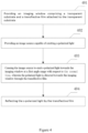
Figure 4 is an exemplary flow chart of a displaying method. - In order to make the object, technical solution and advantages of the present invention clearer, the present invention will be described in further detail with reference to the accompanying drawings.
- For purposes of brevity and intuition, the solution of the present invention will be described by describing a number of representative embodiments. Numerous details in the embodiments are provided solely to aid in understanding the aspects of the present invention. It will be apparent that the technical solution of the invention may be implemented without being limited to these details. In order to avoid unnecessarily obscuring aspects of the present invention, some embodiments are not described in detail, but only frames are presented. In the following text, "comprising" means "comprising, but is not limited to...", "according to ..." means "at least according to, but not limited to...", and "first", "second" and the like are used for reference to a feature only and are not intended to impose any limitation, e.g., a sequential limitation, on the feature.
-
Figure 1 is an exemplary structural diagram of a displaying system according to one embodiment of the present invention. - As shown in
FIG. 1 , the system includes animage source 1 and an imaging window 2. The imaging window 2 comprises a transparent substrate and atransflective film 3 attached to one side of the substrate. Theimage source 1 emits s-polarized light. The s-polarized light has N spectral lines or bands in the visible light band, wherein N is a positive integer not less than 1, and the FWHM of the spectral lines or bands is 60 nm or less. The s-polarized light is incident on the imaging window 2 through thetransflective film 3. Thetransflective film 3 has an average reflectivity greater than 50% for a waveband within the FWHM of at least one of the N spectral lines or bands of the s-polarized light emitted by the image source. The imaging window 2 also allows transmission of ambient light. In the embodiment shown inFIG. 1 , the imaging window 2 further comprises an antireflection film 4 (it is to be understood, an antireflection film may not be used in other embodiments), which is attached to the other side of the substrate. The antireflection film 4 can increase the ambient light transmissivity of the imaging window 2. - The
image source 1 may be a displaying apparatus, or a virtual image or a real image formed by such displaying apparatus. - For example, the displaying apparatus may be a liquid crystal screen, wherein the backlight light source of the liquid crystal screen may be a laser, a light emitting diode, an organic light emitting diode, an excited fluorescent light emitting material, a quantum dot excitation light source, or combinations thereof; the displaying apparatus may also be an active emitting lattice screen composed of a light-emitting point light source such as an LED, an OLED, a plasma light emitting point, or the like; the displaying apparatus may also be a projection imaging system based on such projection techniques such as DLP, LCOS and LCD, with the light source of LED, OLED, laser, or fluorescent light source or a combination thereof, reflected or transmitted through a display panel such as a DMD, an LCOS, and an LCD, and projected onto a projection screen via a projection lens for imaging; the displaying apparatus may also be a projection imaging system which images as the laser beams scan on a screen.
- The real or virtual image formed by all the above-mentioned displaying apparatuses through a single or multiple times of refractions or reflections can also be used as an image source.
- The substrate of the imaging window 2 may be made of a transparent material such as a PC resin, a PET resin, a PMMA resin, glass, quartz, or the like, and may also be subjected to a special treatment to have both transparent and color-changing properties. For example, in strong light conditions, the substrate may change color to reduce ambient light intensity.
- The
transflective film 3 may be arranged to cover the entire inner surface of the substrate, or may cover part of the inner surface of the substrate. Thetransflective film 3 is formed by stacking multiple film layers having different refractive indexes, wherein the composition of each film layer is selected from oxides, fluorides, nitrides, and the like, such as tantalum pentoxide, titanium oxide, magnesium oxide, zinc oxide, zirconium oxide, silicon dioxide, magnesium fluoride, silicon nitride, silicon oxynitride, aluminum fluoride, or combinations thereof. - The higher the average reflectivity of the
transflective film 3 for the s-polarized light in the visible light range, the greater the intensity of the visible light reflected by thetransflective film 3 to the observer. It has been found through test that the average reflectivity of thetransflective film 3 for wavebands within FWHM of at least one of the N spectral lines or bands of the s-polarized light emitted by the image source is greater than a specific reflectivity, for example, greater than 50%, preferably greater than 60%, 70%, 80%, or 90%, and more preferably greater than 95%; the average reflectivity of thetransflective film 3 for visible light band outside the FWHM of the N spectral lines or bands of the s-polarized light emitted by the image source is lower than the average reflectivity of thetransflective film 3 for the waveband within FWHM of the N spectral lines or bands of the s-polarized light emitted by the image source which is greater than said specific reflectivity by at least 5%, preferably 10%, 15%, or even 20%. In addition, thetransflective film 3 has an average transmissivity greater than 60%, preferably greater than 70%, 80%, or 90%, more preferably even more than 95% for p-polarized light in the visible light range. - Alternatively, in some embodiments, the average reflectivity of the
transflective film 3 for a waveband within FWHM of the N spectral lines or bands of the s-polarized light emitted by theimage source 1 is not greater than 50%, but in the range between 25% and 50%. In this case, an antireflection film 4 is used (the antireflection film 4 will be described in detail later). - In one embodiment, the s-polarized light incident on the
transflective film 3 from the image source has three spectral lines or bands in the visible light band. The average reflectivity of thetransflective film 3 for a waveband within the FWHM of the three spectral lines or bands is greater than 50%. The average reflectivity of thetransflective film 3 for visible light band outside the FWHM of the three spectral lines or bands of the s-polarized light emitted from theimage source 1 is lower than the average reflectivity (which is greater than 50%) of thetransflective film 3 for the waveband within the FWHM of the three spectral lines or bands of the s-polarized light emitted from the image source by at least 5% or even 10%. In addition, the transflective film has an average transmissivity greater than 60% for p-polarized light in the visible light range. - In another embodiment not covered by
claim 1 but possibly by claim 10, the s-polarized light incident on thetransflective film 3 from the image source also has three spectral lines or bands in the visible light band. However, thetransflective film 3 has an average reflectivity greater than 50% for the waveband within the FWHM of just one or two of the three spectral lines or bands. Thetransflective film 3 has an average reflectivity for the visible light band outside the FWHM of the three spectral lines or bands of the s-polarized light emitted from theimage source 1 lower than the average reflectivity for the waveband within the FWHM of the three spectral lines or bands of the s-polarized light emitted from the image source by at least 5% or even 10%. - It is to be understood that in another embodiment, the number of spectral lines or bands of the s-polarized light incident on the
transflective film 3 from the image source in the visible light band may be any positive integer not less than 1 (denoted by n). Thetransflective film 3 has an average reflectivity greater than 50% for a waveband within the FWHM of at least one of the N spectral lines or bands. Thetransflective film 3 has an average reflectivity for the visible light band outside the FWHM of the N spectral lines or bands of the s-polarized light emitted from theimage source 1 lower than the average reflectivity (which is greater than 50%) for a waveband within the FWHM of the N spectral lines or bands of the s-polarized light emitted from the image source by at least 5% or even 10%. - Similar to the
transflective film 3, the anti-reflection film 4 may cover the entire outer surface of the substrate, or may cover only a portion of the outer surface of the substrate. The anti-reflection film increases the average transmissivity of the imaging window for visible light by more than 3%. - As shown in
FIG. 1 , the incident angle of the s-polarized light to thetransflective film 3 is α, where α ranges from 30 to 89 degrees. In order to achieve a better reflection and transmission effect, the value of α is preferably close to the angle tan-1(n2/n1), where n1 is the refractive index of the incident medium and n2 is the refractive index of the substrate medium. For example, when n1 = 1.0, n2 = 1.52, then tan-1(n2/n1) is about 56 degrees 40 minutes; when n1=1.0, n2=1.58, tan-1 (n2/n1) is about 57 degrees 40 minutes; when n1=1.0, n2=1.49, tan-1 (n2/n1) is about 56 degrees 08 minutes. The range of α is therefore preferably in the range of 50 to 75 degrees. - The range and preferred angles of α have been exemplified above and those skilled in the art will appreciate that depending on the refractive index of the substrate medium and the refractive index of the incident medium, the angle of α may also be in other ranges.
- As further shown in
FIG. 1 , there is an angle θ between theimage source 1 and the imaging window 2, wherein the angle θ is in the range of 20 to 70 degrees. Of course, the angle θ may also be a value in other ranges; for example, in some embodiments, the angle θ ranges from 80 degrees to 90 degrees. - The spectrum of
image source 1 can be comprised of one or several monochromatic spectral lines bands. For example, with reference to the exemplary schematic diagram of the source image spectrum shown inFIG. 2 , in order to display color image, the s-polarized light emitted by theimage source 1 may be superimposed by three spectral line or band distributions having the peak in the range of 590 nm to 690 nm (red), 500 nm to 565 nm (green), 410 nm to 480 nm (blue), respectively. The average reflectivity of thetransflective film 3 for s-polarized wavebands within the FWHM of the three spectral lines or bands is greater than 60%. Preferably, the average transmissivity of thetransflective film 3 for s-polarized light outside the FWHM of the three spectral lines or bands is greater than 60%. - In a preferred embodiment, the light source of the image source consists of a three-color laser with the peak positions of the three colors being 445 nm (blue), 532 nm (green), 635 nm (red), respectively. The FWHM of each peak is only about 1-2nm (see the laser projection spectrum indicated by the solid line in
FIG. 2 ). - While particular wavelength bands of s-polarized light are described above using red, green and blue colors as examples, those skilled in the art will appreciate that the description is exemplary only and is not intended to limit the scope of the invention.
- Referring again to
FIG. 1 , the s-polarized light emitted by theimage source 1 is incident on thetransflective film 3 of the imaging window 2. Thetransflective film 3 has an average reflectivity greater than, for example, 60% for wavebands within the FWHM of at least one of N spectral lines or bands of s-polarized light, whereby the image of theimage source 1 is re-imaged through the imaging window 2. Further, the ambient light outside the imaging window 2 can penetrate through the imaging window at a relatively high transmissivity (for example, 70% or more), which can form a clear and natural image when incident on the observer's eyes. Thus, the observer can simultaneously view the displayed images of theimage source 1 as well as the ambient light. -
FIG. 3 is an exemplary structural diagram of an imaging window according to an embodiment of the present invention. Referring toFIG. 3 , the imaging window 2 includes a substrate having an inner surface and an outer surface. Atransflective film 3 is disposed on the inner surface of the substrate, and an antireflection film 4 is further provided on the outer surface. - In a preferred embodiment, the
image source 1 may use s-polarized light having three colors of red, green and blue. For example, the three colors are in the three wavebands of 630 nm ± 10 nm (red), 540 nm ± 10 nm (green), 450 nm ± 10 nm (blue), respectively. - In one embodiment of the present invention, the transflective film coated on the inner surface of the substrate has the following optical characteristics:
- (1) for p-polarized light, the transflective film has a transmissivity greater than 95% for all bands;
- (2) for s-polarized light, the transflective film has an average reflectivity greater than 70% for one or more optical wavebands corresponding to the image source. For example, it has an average reflectivity greater than 70% for the three bands of 630 nm ± 10 nm (red), 540 nm ± 10 nm (green), and 450 nm ± 10 nm (blue), and has an average transmissivity greater than 70% for other wavebands.
- The ghost image problem is first analyzed in the absence of an antireflection film. Assuming that the transflective film on the inner surface has an average reflectivity of 70% for a particular s-polarized light having one or more spectral lines or bands and has an average transmissivity greater than 70% for other bands; and the outer surface has a transmissivity of 90% for natural light. Then when the s-polarized light having said one or more optical bands is incident on the transflective film and reflected by the transflective film, the intensity of the primary reflection light of the s-polarized light is about 70% of the intensity of the incident light and the intensity of the s-polarized light refracted into the substrate is about 30% of the intensity of the incident light. The s-polarized light refracted into the substrate will be reflected a second time by the outer surface film, and the light intensity after the secondary reflection is 30% * (1-90%); the secondary reflection light is incident on the transflective film, and the intensity of the light refracted by the transflective film is 30%*(1-90%)*(1-70%) = 0.9%.
- It can be seen that the intensity of the refracted light is almost negligible compared to the intensity of the primary reflection light. Therefore, no obvious ghost image will be formed in the present invention, thus overcoming the ghost image problem commonly encountered in the prior art using s-polarized light.
- The antireflection film coated on the outer surface of the substrate enables the outer surface of the imaging window to achieve an average transmissivity greater than 95% for the entire natural light spectrum under normal daylight conditions.
- Next, the ghost image problem is analyzed in conjunction with the transflective film and the anti-reflection film in the above-described embodiment. Assuming that the transflective film on the inner surface has an average reflectivity of 70% for a particular s-polarized light having one or more spectral lines or bands and has an average transmissivity greater than 70% for other bands; and the outer surface has a transmissivity of 95% for natural light due to the presence of the anti-reflection film. Then when the s-polarized light having said one or more optical bands is incident on the transflective film and reflected by the transflective film, the intensity of the primary reflection light of the s-polarized light is about 70% of the intensity of the incident light and the intensity of the s-polarized light refracted into the substrate is about 30% of the intensity of the incident light. The s-polarized light refracted into the substrate will be reflected a second time by the anti-reflection film, and the light intensity after the secondary reflection is 30% * (1-95%); the secondary reflection light is incident on the transflective film, and the intensity of the light refracted by the transflective film is 30%*(1-95%)*(1-70%) = 0.45%.
- It can be seen that with the specific structure in which the inner surface of the substrate is provided with a transflective film and the outer surface thereof is provided with an anti-reflection film, the imaging window of the present invention further significantly reduces the ghost image problem.
- Next, the combined transmissivity and reflectivity in said embodiment is analyzed in accordance with the optical characteristics of the above-mentioned transflective film:
- (1) reflectivity: since the image source adopts s-polarized light, and since the reflection characteristic of the coating has high correspondence with the image source, it can be known from the reflection characteristics of the coating that the average reflectivity R > 70%;
- (2) transmissivity: under general circumstances, assuming that the ambient natural light contains 50% p-polarized light and 50% s-polarized light; for p-polarized light, the average transmissivity is above 90%; for s-polarized light, and the average transmissivity thereof in the visible band (about 400 nm to 700 nm) is { (20+20+20)*0.3+[700-400-(20+20+20)]*0.7 } /(700-400)≈62%; thus the average transmissivity for the entire natural light T≈95%*50%+62%*50%= 78.5%.
- In summary, due to the use of an image source having characteristics and a coating having a reflection characteristic corresponding to the source characteristics of the image source, the present invention can achieve a sum of the average transmissivity for visible light T and the average reflectivity R for a particular light source of the image source greater than 148.5% (T + R> 148.5%), thereby obtaining an imaging effect with both high transmissivity and high reflectivity.
- In addition, the narrower the FWHM of the light source spectrum and the reflection characteristic spectrum of the reflective film is, the higher transmissivity can be obtained while ensuring the reflectivity.
- In a more preferred embodiment, the light source for a set of image sources shown in
FIG. 2 consists of a three-color laser with the peak positions of the three colors being 445 nm (blue), 532 nm (green), 635 nm (red), respectively. The FWHM of each peak is only about 1-2 nm (see the laser projection spectrum indicated by solid line inFIG. 2 ). With such a light source, a special corresponding transflective film is adopted for a particular angle range, for example, a range where the first angle is 55 degrees to 65 degrees. Said transflective film has a reflectivity of 95% for s-polarized light in the three spectral bands 444 nm to 446 nm, 531 nm to 533 nm, and 634 nm to 636 nm, has a transmissivity of 95% for s-polarized light outside the three bands, and has transmissivity of 95% for p-polarized light in the visible light range. - The combined transmissivity and reflectivity in said embodiment is analyzed as follows:
- (1) reflectivity: since the image source adopts s-polarized light, and since the reflection characteristic of the coating has high correspondence with the image source, it can be known from the reflection characteristic of the coating that the average reflectivity R > 95%;
- (2) transmissivity: under general circumstances, assuming that the ambient natural light contains 50% p-polarized light and 50% s-polarized light; for p-polarized light, the average transmissivity is above 90%; for s-polarized light, and the average transmissivity thereof in the visible band (about 400 nm to 700 nm) is {(2+2+2)*0.05+[700-400-(2+2+2)]*0.95} /(700-400)≈93.2%; thus the average transmissivity for the entire natural light T≈95%*50%+93.2%*50% =94.25%.
- In summary, due to the use of an image source having polarization and spectra characteristics and a coating having a reflection characteristic corresponding to the characteristics of the image source, the present invention can achieve a sum of the average transmissivity for visible light T and the average reflectivity R for a particular light source of the image source greater than 189% (T + R> 189%), thereby obtaining an imaging effect with both high transmissivity and high reflectivity.
-
FIG. 4 is an exemplary flow chart of a displaying method. As shown, the method comprises: - step 401: providing an imaging window comprising a transparent substrate and a transflective film attached to the transparent substrate;
- step 402: providing an image source capable of emitting s-polarized light;
- step 403: causing the image source to emit s-polarized light to the imaging window in a first angle range with respect to the normal line, wherein the polarized light is directed toward the imaging window through the transflective film;
- step 404: reflecting the s-polarized light by the transflective film;
- wherein the s-polarized light has N spectral lines or bands in the visible light band, where N is a positive integer not less than 1, and preferably N is equal to or greater than 3; the FWHM of the spectral lines or bands is less than or equal to 60 nm; wherein within said first angle range, the transflective film has an average reflectivity greater than 50% for wavebands within the FWHM of at least one of the N spectral lines or bands of the s-polarized light emitted by the image source; the transflective film has an average reflectivity for visible light band outside the FWHM of the N spectral lines or bands of the s-polarized light emitted by the image source at least 5% and even 10% lower than the average reflectivity greater than 50% for wavebands within the FWHM of the N spectral lines or bands of the s-polarized light emitted by the image source; wherein the transflective film has an average transmissivity greater than 60% for p-polarized light in the visible range within the second angle range with respect to the normal line, wherein the first angle range is 30 to 89 degrees, preferably 50 degrees to 75 degrees; and the second angle range is 30 degrees to 80 degrees, preferably 55 degrees to 70 degrees.
- In another embodiment, the s-polarized light has N spectral lines or bands in the visible light band, where N is a positive integer not less than 1, and preferably N is equal to or greater than 3; the FWHM of the spectral lines or bands is less than or equal to 60 nm; wherein within said first angle range, the transflective film has an average reflectivity in the range of 25% to 50% for wavebands within the FWHM of the 3 or more spectral lines or bands of the s-polarized light emitted by the image source, and has an average reflectivity for visible light band outside the FWHM of the N spectral lines or bands of the s-polarized light at least 5% lower than the average reflectivity for the former; and said transflective film has an average transmissivity greater than 60% for p-polarized light in the visible range within said second angle range with respect to the normal line.
- The displaying system of the present invention can be applied in a variety of applications, e.g., to various head-up displays (HUDs) when used together with a base or pedestal; of course, they can also be used in vehicles such as automobiles or aircrafts.
- According to the present invention, light from the image source and ambient light can be incident to the observer's eyes at the same time to form a clear image, thereby presenting the image of the image source to the observer's eyes without affecting the observer's observation of the external environment. In the embodiments of the present invention, s-polarized three-color lights are used as the image source of reflection, and meanwhile an imaging window with s-polarized narrow-band high-reflectivity film is used. Since the spectral bands of the image source and the transflective film are well matched, and since the s-polarized light is not affected by a Brewster's angle, the reflectivity of the light from the image source is greatly improved as compared with the conventional technique, the utilization efficiency of the reflection light is high, and thus the entire optical system can be realized with a lower power consumption. In addition, since a high reflectivity can be obtained on a transflective film on the inner surface of the substrate, and since an antireflection film is provided on the outer surface of the substrate, the ghost image problem can be well suppressed. Further, the observer's perception of the ambient light is almost not affected, since the same optical information can be obtained from the p-polarized ambient light, even if some band of the s-polarized spectrum of the ambient light is filtered.
- The foregoing description of the disclosed embodiments will enable those skilled in the art to carry out or use the present invention. It is to be understood that the features disclosed in the above embodiments may be used alone or in combination, unless otherwise specified. Numerous modifications to these embodiments will be readily apparent to those skilled in the art, and the general principles defined herein may be implemented in other embodiments without departing from the scope of the invention as defined by the appended claims.
Claims (16)
- A displaying system, comprising:an imaging window (2) including a transparent substrate and a transflective film (3) attached to a first surface of the transparent substrate; andan image source (1) that emits s-polarized light incident on the imaging window (2) through the transflective film (3),characterized by that,light emitted by the image source (1) before reaching the transflective film (3) only includes the s-polarized light, wherein the s-polarized light emitted by the image source (1) before reaching the transflective film (3) has N spectral lines or bands in the visible light band, wherein N is a positive integer not less than 1;wherein the N spectral lines or bands each have a FWHM (full-width at half-maximum) equal to or less than 60 nm, and for each of the N spectral lines or bands in the visible spectra of the s-polarized light emitted from the image source (1), a major band is defined as the spectra band centered at the peak of the line or the band and expanding up to the FWHM so that the N spectral lines or bands include N maj or bands;the transflective film (3) being capable of reflecting the s-polarized light emitted by the image source (1) at a first angle with respect to the normal line, and meanwhile capable of transmitting ambient light at a second angle with respect to the normal line, wherein the first angle has a first angle range from 30 to 89 degrees, and the second angle has a second angle range from 30 degrees to 80 degrees;at said first angle, the transflective film (3) has a first average reflectivity for the s-polarized light emitted by the image source (1) in at least one major band of the N major bands, and has a second average reflectivity for the s-polarized light emitted by the image source (1) in visible bands outside the at least one major band, wherein the first average reflectivity is different from the second average reflectivity,at said first angle, an average reflectivity of the transflective film (3) for the s-polarized light emitted by the image source (1) in each of the N major bands is greater than 50%; at said first angle, an average s-polarized reflectivity of the transflective film (3) for visible bands outside the N major bands is at least 5% lower than that for the at least one major band;at the second angle, the transflective film (3) has an average transmissivity greater than 60% for p-polarized light in both of the at least one major band and the visible bands outside the at least one major band, whereinthe transflective film (3) is formed by stacking at least two types of film layers having different refractive indexes, the composition of the film layer being selected from one or more of tantalum pentoxide, titanium oxide, magnesium oxide, zinc oxide, zirconium oxide, silicon dioxide, magnesium fluoride, silicon nitride, silicon oxynitride, and aluminum fluoride.
- The displaying system according to claim 1, whereinthe transflective film (3) reflects a first portion of the s-polarized light at the first angle with respect to the normal line as first light,the transparent substrate further includes a second surface opposite to the first surface, the second surface reflects a second portion of the s-polarized light as second light and transmits a third portion of the s-polarized light as third light and whereinthe first light, the second light and the third light are all s-polarized light.
- The displaying system according to claim 2, wherein an antireflection film (4) is disposed on the second surface of the transparent substrate so that the s-polarized light incident on the imaging window (2) subsequently through the transflective film (3), the transparent substrate and the antireflection film (4);the antireflection film (4) reflects the second portion of the s-polarized light as the second light and transmits the third portion of the s-polarized light to the air as the third light;the antireflection film (4) increases an average transmissivity of the display window (2) for visible light by 3% or more as compared with a situation where the antireflection film (4) is not disposed.
- The displaying system according to claim 1, wherein the N spectral lines or bands comprise at least three spectral lines or bands, wherein a peak position of the first spectral line or band is in the range of 410 nm to 480 nm, a peak position of the second spectral line or band is in the range of 500 nm to 565 nm, and a peak position of the third spectral line or band is in the range of 590 nm to 690 nm.
- The displaying system according to claim 1, wherein the first angle range is 50 degrees to 75 degrees and/or the second angle range is 55 degrees to 70 degrees.
- The displaying system according to claim 1, wherein the transflective film (3), within the second angle range, has an average transmissivity greater than 80% for the p-polarized light in the visible range.
- The displaying system according to claim 1, wherein the transflective film (3) has an average reflectivity greater than 70% for the N major bands within said first angle range; and the transflective film (3) has an average reflectivity less than 50% for visible light band outside the N major bands.
- The displaying system according to any of claims 1-7, wherein the image source (1) is a displaying apparatus that emits a virtual image or a real image, or a virtual or real image formed by such displaying apparatus.
- The displaying system according to any of claims 1-7, wherein a light source of the image source (1) comprises a laser, a light emitting diode, an organic light emitting diode, an excited fluorescent light emitting material, a quantum dot excitation light source, or any combinations thereof.
- A displaying system, comprising:an imaging window (2) including a transparent substrate having a first surface and a second surface, and a transflective film (3) attached to the first surface of the transparent substrate; andan image source (1) for emitting s-polarized light incident on the imaging window (2) through the transflective film,characterized by that,light emitted by the image source (1) before reaching the transflective film (3) only including the s-polarized light, wherein the s-polarized light emitted by the image source (1) before reaching the transflective film (3) has N spectral lines or bands in the visible light band, wherein N is a positive integer not less than 1;wherein the spectral lines or bands have a FWHM equal to or less than 60 nm, and for each of the N spectral lines or bands in the visible spectra of the s-polarized light emitted from the image source (1), a major band is defined as the spectra band centered at the peak of the line or the band and expanding up to the FWHM;the transflective film (3) being capable of reflecting the s-polarized light emitted by the image source (1) at a first angle with respect to the normal line, and also capable of transmitting ambient light at a second angle with respect to the normal line, wherein the first angle has a first angle range from 30 to 89 degrees, and the second angle has a second angle range from 30 degrees to 80 degrees;at said first angle, the transflective film (3) has an average reflectivity in the range of 25% to 50% for the N major bands; the transflective film (3) has an average reflectivity for visible light bands outside the N major bands at least 5% lower than the average reflectivity for the N major bands;said transflective film (3) has an average transmissivity greater than 60% for p-polarized light in the visible range at said second angle; andthe displaying system further comprises an antireflection film (4) attached to the second surface of the transparent substrate, the antireflection film (3) increases the average transmissivity of the imaging window (2) for visible light by at least 3% as compared with a situation where the antireflection film (4) is not disposed, whereinthe s-polarized light incident on the imaging window (2) subsequently through the transflective film (3), the transparent substrate and the antireflection film (4) so that the transflective film (3) reflects a first portion of the s-polarized light at the first angle with respect to the normal line as first light, the antireflection film (4) reflects a second portion of the s-polarized light as second light and transmits a third portion of the s-polarized light to the air as third light, and the first light, the second light and the third light are all s-polarized light, and whereinthe transflective film (3) is formed by stacking at least two types of film layers having different refractive indexes, the composition of the film layer being selected from one or more of tantalum pentoxide, titanium oxide, magnesium oxide, zinc oxide, zirconium oxide, silicon dioxide, magnesium fluoride, silicon nitride, silicon oxynitride, and aluminum fluoride.
- The displaying system according to claim 10, wherein the N spectral lines or bands comprise at least three spectral lines or bands, wherein a peak position of the first spectral line or band is in the range of 410 nm to 480 nm; a peak position of the second spectral line or band is in the range of 500 nm to 565 nm, and a peak position of the third spectral line or band is in the range of 590 nm to 690 nm.
- The displaying system according to claim 10, wherein the first angle range is 50 degrees to 75 degrees, and/or the second angle range is 55 degrees to 70 degrees.
- The displaying system according to claim 10, wherein the transflective film (3), within the second angle range, has an average transmissivity greater than 80% for the p-polarized light in the visible range.
- The displaying system according to any of claims 10-13, wherein the image source (1) is a displaying apparatus that emits a virtual image or a real image, or a virtual or real image formed by such displaying apparatus.
- The displaying system according to any of claims 10-13, wherein a light source of the image source (1) comprises a laser, a light emitting diode, an organic light emitting diode, an excited fluorescent light emitting material, a quantum dot excitation light source, or any combinations thereof.
- A vehicle comprising a displaying system according to any of claims 1-15.
Applications Claiming Priority (3)
| Application Number | Priority Date | Filing Date | Title |
|---|---|---|---|
| CN201610151142 | 2016-03-17 | ||
| CN201610971143.6A CN107203042B (en) | 2016-03-17 | 2016-11-09 | Display imaging system and method and vehicle with same |
| PCT/CN2017/074181 WO2017157136A1 (en) | 2016-03-17 | 2017-02-20 | Display imaging system and method, and vehicle carrying the system |
Publications (4)
| Publication Number | Publication Date |
|---|---|
| EP3432050A1 EP3432050A1 (en) | 2019-01-23 |
| EP3432050A4 EP3432050A4 (en) | 2019-11-20 |
| EP3432050B1 true EP3432050B1 (en) | 2023-12-27 |
| EP3432050C0 EP3432050C0 (en) | 2023-12-27 |
Family
ID=59904504
Family Applications (1)
| Application Number | Title | Priority Date | Filing Date |
|---|---|---|---|
| EP17765678.2A Active EP3432050B1 (en) | 2016-03-17 | 2017-02-20 | Display imaging system and method, and vehicle carrying the system |
Country Status (4)
| Country | Link |
|---|---|
| EP (1) | EP3432050B1 (en) |
| JP (1) | JP7315194B2 (en) |
| KR (1) | KR102746159B1 (en) |
| CN (1) | CN107203042B (en) |
Families Citing this family (14)
| Publication number | Priority date | Publication date | Assignee | Title |
|---|---|---|---|---|
| US10684492B2 (en) * | 2016-12-08 | 2020-06-16 | Futurus Technology Co., Ltd. | System for imaging in the air |
| CN108181708B (en) * | 2018-01-02 | 2020-12-15 | 京东方科技集团股份有限公司 | A head-up display system and its control method |
| CN111458871A (en) * | 2019-01-21 | 2020-07-28 | 未来(北京)黑科技有限公司 | Developing system and developing method |
| CN111458870A (en) * | 2019-01-21 | 2020-07-28 | 未来(北京)黑科技有限公司 | Transparent imaging device and application thereof |
| CN111458919A (en) * | 2019-01-21 | 2020-07-28 | 未来(北京)黑科技有限公司 | Display system and display method |
| CN111458869A (en) * | 2019-01-21 | 2020-07-28 | 未来(北京)黑科技有限公司 | Reflective transparent display device and application thereof |
| CN110045502A (en) * | 2019-03-23 | 2019-07-23 | 深圳京龙睿信科技有限公司 | Head up display |
| EP4147088A4 (en) * | 2020-05-08 | 2024-06-12 | 3M Innovative Properties Company | DISPLAY SYSTEM FOR A VEHICLE |
| CN111766604B (en) * | 2020-06-09 | 2023-03-03 | 中国电子科技集团公司第十一研究所 | Composite distance measurement method and system |
| CN112130325B (en) * | 2020-09-25 | 2022-07-12 | 东风汽车有限公司 | Parallax correction system and method for vehicle-mounted head-up display, storage medium and electronic device |
| CN113960795B (en) * | 2021-09-18 | 2023-03-28 | 福耀玻璃工业集团股份有限公司 | Display window and vehicle |
| CN115327779A (en) * | 2022-09-02 | 2022-11-11 | 深圳市光途显示科技有限公司 | Display device |
| CN115527472B (en) * | 2022-09-23 | 2025-07-04 | 业成光电(深圳)有限公司 | Ghost Measurement Method for Head-Up Display |
| WO2024066880A1 (en) * | 2022-09-26 | 2024-04-04 | 未来(北京)黑科技有限公司 | S-polarized light transflective film, windshield window, display apparatus, and transportation device |
Citations (1)
| Publication number | Priority date | Publication date | Assignee | Title |
|---|---|---|---|---|
| JPH11249062A (en) * | 1998-03-04 | 1999-09-17 | Asahi Glass Co Ltd | Information display device |
Family Cites Families (16)
| Publication number | Priority date | Publication date | Assignee | Title |
|---|---|---|---|---|
| EP0962806B1 (en) * | 1993-12-21 | 2008-12-03 | Minnesota Mining And Manufacturing Company | Multilayered optical film |
| JPH10148787A (en) * | 1996-11-20 | 1998-06-02 | Central Glass Co Ltd | Display device |
| US6447120B2 (en) * | 1999-07-28 | 2002-09-10 | Moxtex | Image projection system with a polarizing beam splitter |
| US7203005B2 (en) * | 2002-05-22 | 2007-04-10 | Chelix Technologies, Inc. | Real image configuration for a high efficiency heads-up display (HUD) using a polarizing mirror and a polarization preserving screen |
| FR2847988B1 (en) * | 2002-12-03 | 2005-02-25 | Essilor Int | POLARIZATION SEPARATOR, PROCESS FOR MANUFACTURING THE SAME, AND OPHTHALMIC LENS HAVING PROJECTION INSERTS CONTAINING THE SAME |
| US6952312B2 (en) * | 2002-12-31 | 2005-10-04 | 3M Innovative Properties Company | Head-up display with polarized light source and wide-angle p-polarization reflective polarizer |
| US7158095B2 (en) * | 2003-07-17 | 2007-01-02 | Big Buddy Performance, Inc. | Visual display system for displaying virtual images onto a field of vision |
| US7482996B2 (en) * | 2004-06-28 | 2009-01-27 | Honeywell International Inc. | Head-up display |
| JP5101257B2 (en) * | 2007-11-26 | 2012-12-19 | 株式会社東芝 | Optical film for head-up display, head-up display, and moving body |
| CN103140791B (en) * | 2010-10-01 | 2016-03-30 | 松下知识产权经营株式会社 | The vehicle of perspective display device and lift-launch perspective display device |
| CN103018796B (en) * | 2012-10-31 | 2015-02-18 | 南京工业大学 | Double-film PC (Polycarbonate) lens for optical display and preparation method thereof |
| JP2015025977A (en) * | 2013-07-26 | 2015-02-05 | 日本精機株式会社 | Scanning projection device |
| JP6340807B2 (en) * | 2014-02-05 | 2018-06-13 | 株式会社リコー | Image display device and moving body |
| US9977246B2 (en) * | 2014-03-18 | 2018-05-22 | 3M Innovative Properties Company | Low profile image combiner for near-eye displays |
| WO2015177833A1 (en) | 2014-05-19 | 2015-11-26 | パイオニア株式会社 | Virtual image generating element and head-up display |
| CN105093534A (en) * | 2015-08-21 | 2015-11-25 | 杨毅 | Display screen and display apparatus |
-
2016
- 2016-11-09 CN CN201610971143.6A patent/CN107203042B/en active Active
-
2017
- 2017-02-20 KR KR1020187029811A patent/KR102746159B1/en active Active
- 2017-02-20 JP JP2018568476A patent/JP7315194B2/en active Active
- 2017-02-20 EP EP17765678.2A patent/EP3432050B1/en active Active
Patent Citations (1)
| Publication number | Priority date | Publication date | Assignee | Title |
|---|---|---|---|---|
| JPH11249062A (en) * | 1998-03-04 | 1999-09-17 | Asahi Glass Co Ltd | Information display device |
Also Published As
| Publication number | Publication date |
|---|---|
| EP3432050A1 (en) | 2019-01-23 |
| CN107203042B (en) | 2021-12-24 |
| JP2019512754A (en) | 2019-05-16 |
| CN107203042A (en) | 2017-09-26 |
| EP3432050A4 (en) | 2019-11-20 |
| KR20190009278A (en) | 2019-01-28 |
| KR102746159B1 (en) | 2024-12-26 |
| EP3432050C0 (en) | 2023-12-27 |
| JP7315194B2 (en) | 2023-07-26 |
Similar Documents
| Publication | Publication Date | Title |
|---|---|---|
| EP3432050A1 (en) | Display imaging system and method, and vehicle carrying the system | |
| US11397323B2 (en) | Displaying system, method, and vehicle | |
| US6952312B2 (en) | Head-up display with polarized light source and wide-angle p-polarization reflective polarizer | |
| US7320534B2 (en) | Display device | |
| US12403674B2 (en) | Glass laminate including reflective film | |
| CN109219767B (en) | Head-up display device and cold mirror | |
| CN106990530B (en) | Cold mirror for head-up display device and head-up display device | |
| RU2667310C2 (en) | Display device for transparent glass | |
| CN106255917A (en) | Reflective projection type display device | |
| CA2485672A1 (en) | Projection display system | |
| CN114077052A (en) | Multilayer image display device, head-up display, and transportation apparatus | |
| WO2018025518A1 (en) | Head-up display device | |
| US20220187603A1 (en) | An optical system | |
| JP2003344801A (en) | Display device | |
| JP2022090496A (en) | Virtual image display device and cold mirror | |
| JP4507506B2 (en) | Image display system | |
| US10663743B2 (en) | Optical wavelength conversion module and illumination module | |
| US20260003186A1 (en) | Windshield glass and head-up display system | |
| CN218824979U (en) | Head-up display device and traffic equipment | |
| EP4147088A1 (en) | Display system for vehicle | |
| WO2020244035A1 (en) | Virtual image display apparatus | |
| HK1087181A (en) | Head-up display with polarized light source and wide-angle p-polarization reflective polarizer |
Legal Events
| Date | Code | Title | Description |
|---|---|---|---|
| STAA | Information on the status of an ep patent application or granted ep patent |
Free format text: STATUS: THE INTERNATIONAL PUBLICATION HAS BEEN MADE |
|
| PUAI | Public reference made under article 153(3) epc to a published international application that has entered the european phase |
Free format text: ORIGINAL CODE: 0009012 |
|
| STAA | Information on the status of an ep patent application or granted ep patent |
Free format text: STATUS: REQUEST FOR EXAMINATION WAS MADE |
|
| 17P | Request for examination filed |
Effective date: 20180912 |
|
| AK | Designated contracting states |
Kind code of ref document: A1 Designated state(s): AL AT BE BG CH CY CZ DE DK EE ES FI FR GB GR HR HU IE IS IT LI LT LU LV MC MK MT NL NO PL PT RO RS SE SI SK SM TR |
|
| AX | Request for extension of the european patent |
Extension state: BA ME |
|
| DAV | Request for validation of the european patent (deleted) | ||
| DAX | Request for extension of the european patent (deleted) | ||
| RAP1 | Party data changed (applicant data changed or rights of an application transferred) |
Owner name: FUTURUS TECHNOLOGY CO., LTD. |
|
| A4 | Supplementary search report drawn up and despatched |
Effective date: 20191021 |
|
| RIC1 | Information provided on ipc code assigned before grant |
Ipc: G02B 5/30 20060101ALI20191015BHEP Ipc: B60K 35/00 20060101ALI20191015BHEP Ipc: G02B 1/11 20150101ALN20191015BHEP Ipc: G02B 27/01 20060101AFI20191015BHEP |
|
| STAA | Information on the status of an ep patent application or granted ep patent |
Free format text: STATUS: EXAMINATION IS IN PROGRESS |
|
| 17Q | First examination report despatched |
Effective date: 20191220 |
|
| GRAP | Despatch of communication of intention to grant a patent |
Free format text: ORIGINAL CODE: EPIDOSNIGR1 |
|
| STAA | Information on the status of an ep patent application or granted ep patent |
Free format text: STATUS: GRANT OF PATENT IS INTENDED |
|
| RIC1 | Information provided on ipc code assigned before grant |
Ipc: G02B 1/11 20150101ALN20230707BHEP Ipc: G02B 5/30 20060101ALI20230707BHEP Ipc: B60K 35/00 20060101ALI20230707BHEP Ipc: G02B 27/01 20060101AFI20230707BHEP |
|
| INTG | Intention to grant announced |
Effective date: 20230728 |
|
| GRAS | Grant fee paid |
Free format text: ORIGINAL CODE: EPIDOSNIGR3 |
|
| GRAA | (expected) grant |
Free format text: ORIGINAL CODE: 0009210 |
|
| STAA | Information on the status of an ep patent application or granted ep patent |
Free format text: STATUS: THE PATENT HAS BEEN GRANTED |
|
| AK | Designated contracting states |
Kind code of ref document: B1 Designated state(s): AL AT BE BG CH CY CZ DE DK EE ES FI FR GB GR HR HU IE IS IT LI LT LU LV MC MK MT NL NO PL PT RO RS SE SI SK SM TR |
|
| REG | Reference to a national code |
Ref country code: GB Ref legal event code: FG4D |
|
| REG | Reference to a national code |
Ref country code: CH Ref legal event code: EP |
|
| REG | Reference to a national code |
Ref country code: DE Ref legal event code: R096 Ref document number: 602017077925 Country of ref document: DE |
|
| REG | Reference to a national code |
Ref country code: IE Ref legal event code: FG4D |
|
| U01 | Request for unitary effect filed |
Effective date: 20231229 |
|
| U07 | Unitary effect registered |
Designated state(s): AT BE BG DE DK EE FI FR IT LT LU LV MT NL PT SE SI Effective date: 20240112 |
|
| PG25 | Lapsed in a contracting state [announced via postgrant information from national office to epo] |
Ref country code: GR Free format text: LAPSE BECAUSE OF FAILURE TO SUBMIT A TRANSLATION OF THE DESCRIPTION OR TO PAY THE FEE WITHIN THE PRESCRIBED TIME-LIMIT Effective date: 20240328 |
|
| PG25 | Lapsed in a contracting state [announced via postgrant information from national office to epo] |
Ref country code: ES Free format text: LAPSE BECAUSE OF FAILURE TO SUBMIT A TRANSLATION OF THE DESCRIPTION OR TO PAY THE FEE WITHIN THE PRESCRIBED TIME-LIMIT Effective date: 20231227 |
|
| PG25 | Lapsed in a contracting state [announced via postgrant information from national office to epo] |
Ref country code: GR Free format text: LAPSE BECAUSE OF FAILURE TO SUBMIT A TRANSLATION OF THE DESCRIPTION OR TO PAY THE FEE WITHIN THE PRESCRIBED TIME-LIMIT Effective date: 20240328 Ref country code: ES Free format text: LAPSE BECAUSE OF FAILURE TO SUBMIT A TRANSLATION OF THE DESCRIPTION OR TO PAY THE FEE WITHIN THE PRESCRIBED TIME-LIMIT Effective date: 20231227 |
|
| PG25 | Lapsed in a contracting state [announced via postgrant information from national office to epo] |
Ref country code: RS Free format text: LAPSE BECAUSE OF FAILURE TO SUBMIT A TRANSLATION OF THE DESCRIPTION OR TO PAY THE FEE WITHIN THE PRESCRIBED TIME-LIMIT Effective date: 20231227 Ref country code: NO Free format text: LAPSE BECAUSE OF FAILURE TO SUBMIT A TRANSLATION OF THE DESCRIPTION OR TO PAY THE FEE WITHIN THE PRESCRIBED TIME-LIMIT Effective date: 20240327 Ref country code: HR Free format text: LAPSE BECAUSE OF FAILURE TO SUBMIT A TRANSLATION OF THE DESCRIPTION OR TO PAY THE FEE WITHIN THE PRESCRIBED TIME-LIMIT Effective date: 20231227 |
|
| PG25 | Lapsed in a contracting state [announced via postgrant information from national office to epo] |
Ref country code: IS Free format text: LAPSE BECAUSE OF FAILURE TO SUBMIT A TRANSLATION OF THE DESCRIPTION OR TO PAY THE FEE WITHIN THE PRESCRIBED TIME-LIMIT Effective date: 20240427 |
|
| PG25 | Lapsed in a contracting state [announced via postgrant information from national office to epo] |
Ref country code: CZ Free format text: LAPSE BECAUSE OF FAILURE TO SUBMIT A TRANSLATION OF THE DESCRIPTION OR TO PAY THE FEE WITHIN THE PRESCRIBED TIME-LIMIT Effective date: 20231227 |
|
| U21 | Renewal fee for the european patent with unitary effect paid with additional fee |
Year of fee payment: 8 Effective date: 20240619 |
|
| PG25 | Lapsed in a contracting state [announced via postgrant information from national office to epo] |
Ref country code: SK Free format text: LAPSE BECAUSE OF FAILURE TO SUBMIT A TRANSLATION OF THE DESCRIPTION OR TO PAY THE FEE WITHIN THE PRESCRIBED TIME-LIMIT Effective date: 20231227 |
|
| PG25 | Lapsed in a contracting state [announced via postgrant information from national office to epo] |
Ref country code: SM Free format text: LAPSE BECAUSE OF FAILURE TO SUBMIT A TRANSLATION OF THE DESCRIPTION OR TO PAY THE FEE WITHIN THE PRESCRIBED TIME-LIMIT Effective date: 20231227 Ref country code: SK Free format text: LAPSE BECAUSE OF FAILURE TO SUBMIT A TRANSLATION OF THE DESCRIPTION OR TO PAY THE FEE WITHIN THE PRESCRIBED TIME-LIMIT Effective date: 20231227 Ref country code: RO Free format text: LAPSE BECAUSE OF FAILURE TO SUBMIT A TRANSLATION OF THE DESCRIPTION OR TO PAY THE FEE WITHIN THE PRESCRIBED TIME-LIMIT Effective date: 20231227 Ref country code: IS Free format text: LAPSE BECAUSE OF FAILURE TO SUBMIT A TRANSLATION OF THE DESCRIPTION OR TO PAY THE FEE WITHIN THE PRESCRIBED TIME-LIMIT Effective date: 20240427 Ref country code: CZ Free format text: LAPSE BECAUSE OF FAILURE TO SUBMIT A TRANSLATION OF THE DESCRIPTION OR TO PAY THE FEE WITHIN THE PRESCRIBED TIME-LIMIT Effective date: 20231227 |
|
| PG25 | Lapsed in a contracting state [announced via postgrant information from national office to epo] |
Ref country code: PL Free format text: LAPSE BECAUSE OF FAILURE TO SUBMIT A TRANSLATION OF THE DESCRIPTION OR TO PAY THE FEE WITHIN THE PRESCRIBED TIME-LIMIT Effective date: 20231227 |
|
| PG25 | Lapsed in a contracting state [announced via postgrant information from national office to epo] |
Ref country code: PL Free format text: LAPSE BECAUSE OF FAILURE TO SUBMIT A TRANSLATION OF THE DESCRIPTION OR TO PAY THE FEE WITHIN THE PRESCRIBED TIME-LIMIT Effective date: 20231227 |
|
| PG25 | Lapsed in a contracting state [announced via postgrant information from national office to epo] |
Ref country code: MC Free format text: LAPSE BECAUSE OF FAILURE TO SUBMIT A TRANSLATION OF THE DESCRIPTION OR TO PAY THE FEE WITHIN THE PRESCRIBED TIME-LIMIT Effective date: 20231227 |
|
| REG | Reference to a national code |
Ref country code: DE Ref legal event code: R097 Ref document number: 602017077925 Country of ref document: DE Ref country code: CH Ref legal event code: PL |
|
| PG25 | Lapsed in a contracting state [announced via postgrant information from national office to epo] |
Ref country code: CH Free format text: LAPSE BECAUSE OF NON-PAYMENT OF DUE FEES Effective date: 20240229 |
|
| PG25 | Lapsed in a contracting state [announced via postgrant information from national office to epo] |
Ref country code: CH Free format text: LAPSE BECAUSE OF NON-PAYMENT OF DUE FEES Effective date: 20240229 |
|
| PLBE | No opposition filed within time limit |
Free format text: ORIGINAL CODE: 0009261 |
|
| STAA | Information on the status of an ep patent application or granted ep patent |
Free format text: STATUS: NO OPPOSITION FILED WITHIN TIME LIMIT |
|
| 26N | No opposition filed |
Effective date: 20240930 |
|
| PG25 | Lapsed in a contracting state [announced via postgrant information from national office to epo] |
Ref country code: IE Free format text: LAPSE BECAUSE OF NON-PAYMENT OF DUE FEES Effective date: 20240220 |
|
| PG25 | Lapsed in a contracting state [announced via postgrant information from national office to epo] |
Ref country code: IE Free format text: LAPSE BECAUSE OF NON-PAYMENT OF DUE FEES Effective date: 20240220 |
|
| U20 | Renewal fee for the european patent with unitary effect paid |
Year of fee payment: 9 Effective date: 20250107 |
|
| PG25 | Lapsed in a contracting state [announced via postgrant information from national office to epo] |
Ref country code: CY Free format text: LAPSE BECAUSE OF FAILURE TO SUBMIT A TRANSLATION OF THE DESCRIPTION OR TO PAY THE FEE WITHIN THE PRESCRIBED TIME-LIMIT; INVALID AB INITIO Effective date: 20170220 |
|
| PG25 | Lapsed in a contracting state [announced via postgrant information from national office to epo] |
Ref country code: HU Free format text: LAPSE BECAUSE OF FAILURE TO SUBMIT A TRANSLATION OF THE DESCRIPTION OR TO PAY THE FEE WITHIN THE PRESCRIBED TIME-LIMIT; INVALID AB INITIO Effective date: 20170220 |
|
| PG25 | Lapsed in a contracting state [announced via postgrant information from national office to epo] |
Ref country code: TR Free format text: LAPSE BECAUSE OF FAILURE TO SUBMIT A TRANSLATION OF THE DESCRIPTION OR TO PAY THE FEE WITHIN THE PRESCRIBED TIME-LIMIT Effective date: 20231227 |
|
| U20 | Renewal fee for the european patent with unitary effect paid |
Year of fee payment: 10 Effective date: 20260106 |
|
| PGFP | Annual fee paid to national office [announced via postgrant information from national office to epo] |
Ref country code: GB Payment date: 20260106 Year of fee payment: 10 |