EP3431922A1 - Internal circumference measurement device for circular member - Google Patents
Internal circumference measurement device for circular member Download PDFInfo
- Publication number
- EP3431922A1 EP3431922A1 EP17766200.4A EP17766200A EP3431922A1 EP 3431922 A1 EP3431922 A1 EP 3431922A1 EP 17766200 A EP17766200 A EP 17766200A EP 3431922 A1 EP3431922 A1 EP 3431922A1
- Authority
- EP
- European Patent Office
- Prior art keywords
- circular member
- dimensional sensor
- inner circumferential
- support
- circumferential length
- Prior art date
- Legal status (The legal status is an assumption and is not a legal conclusion. Google has not performed a legal analysis and makes no representation as to the accuracy of the status listed.)
- Granted
Links
Images


Classifications
-
- G—PHYSICS
- G01—MEASURING; TESTING
- G01B—MEASURING LENGTH, THICKNESS OR SIMILAR LINEAR DIMENSIONS; MEASURING ANGLES; MEASURING AREAS; MEASURING IRREGULARITIES OF SURFACES OR CONTOURS
- G01B11/00—Measuring arrangements characterised by the use of optical techniques
- G01B11/02—Measuring arrangements characterised by the use of optical techniques for measuring length, width or thickness
- G01B11/04—Measuring arrangements characterised by the use of optical techniques for measuring length, width or thickness specially adapted for measuring length or width of objects while moving
- G01B11/043—Measuring arrangements characterised by the use of optical techniques for measuring length, width or thickness specially adapted for measuring length or width of objects while moving for measuring length
-
- G—PHYSICS
- G01—MEASURING; TESTING
- G01B—MEASURING LENGTH, THICKNESS OR SIMILAR LINEAR DIMENSIONS; MEASURING ANGLES; MEASURING AREAS; MEASURING IRREGULARITIES OF SURFACES OR CONTOURS
- G01B11/00—Measuring arrangements characterised by the use of optical techniques
- G01B11/02—Measuring arrangements characterised by the use of optical techniques for measuring length, width or thickness
-
- G—PHYSICS
- G01—MEASURING; TESTING
- G01B—MEASURING LENGTH, THICKNESS OR SIMILAR LINEAR DIMENSIONS; MEASURING ANGLES; MEASURING AREAS; MEASURING IRREGULARITIES OF SURFACES OR CONTOURS
- G01B11/00—Measuring arrangements characterised by the use of optical techniques
- G01B11/02—Measuring arrangements characterised by the use of optical techniques for measuring length, width or thickness
- G01B11/026—Measuring arrangements characterised by the use of optical techniques for measuring length, width or thickness by measuring distance between sensor and object
-
- G—PHYSICS
- G01—MEASURING; TESTING
- G01B—MEASURING LENGTH, THICKNESS OR SIMILAR LINEAR DIMENSIONS; MEASURING ANGLES; MEASURING AREAS; MEASURING IRREGULARITIES OF SURFACES OR CONTOURS
- G01B11/00—Measuring arrangements characterised by the use of optical techniques
- G01B11/08—Measuring arrangements characterised by the use of optical techniques for measuring diameters
- G01B11/12—Measuring arrangements characterised by the use of optical techniques for measuring diameters internal diameters
-
- G—PHYSICS
- G01—MEASURING; TESTING
- G01B—MEASURING LENGTH, THICKNESS OR SIMILAR LINEAR DIMENSIONS; MEASURING ANGLES; MEASURING AREAS; MEASURING IRREGULARITIES OF SURFACES OR CONTOURS
- G01B11/00—Measuring arrangements characterised by the use of optical techniques
- G01B11/24—Measuring arrangements characterised by the use of optical techniques for measuring contours or curvatures
-
- G—PHYSICS
- G01—MEASURING; TESTING
- G01B—MEASURING LENGTH, THICKNESS OR SIMILAR LINEAR DIMENSIONS; MEASURING ANGLES; MEASURING AREAS; MEASURING IRREGULARITIES OF SURFACES OR CONTOURS
- G01B11/00—Measuring arrangements characterised by the use of optical techniques
- G01B11/24—Measuring arrangements characterised by the use of optical techniques for measuring contours or curvatures
- G01B11/255—Measuring arrangements characterised by the use of optical techniques for measuring contours or curvatures for measuring radius of curvature
-
- G—PHYSICS
- G01—MEASURING; TESTING
- G01B—MEASURING LENGTH, THICKNESS OR SIMILAR LINEAR DIMENSIONS; MEASURING ANGLES; MEASURING AREAS; MEASURING IRREGULARITIES OF SURFACES OR CONTOURS
- G01B21/00—Measuring arrangements or details thereof, where the measuring technique is not covered by the other groups of this subclass, unspecified or not relevant
- G01B21/02—Measuring arrangements or details thereof, where the measuring technique is not covered by the other groups of this subclass, unspecified or not relevant for measuring length, width, or thickness
-
- G—PHYSICS
- G01—MEASURING; TESTING
- G01B—MEASURING LENGTH, THICKNESS OR SIMILAR LINEAR DIMENSIONS; MEASURING ANGLES; MEASURING AREAS; MEASURING IRREGULARITIES OF SURFACES OR CONTOURS
- G01B21/00—Measuring arrangements or details thereof, where the measuring technique is not covered by the other groups of this subclass, unspecified or not relevant
- G01B21/10—Measuring arrangements or details thereof, where the measuring technique is not covered by the other groups of this subclass, unspecified or not relevant for measuring diameters
- G01B21/14—Measuring arrangements or details thereof, where the measuring technique is not covered by the other groups of this subclass, unspecified or not relevant for measuring diameters internal diameters
-
- G—PHYSICS
- G01—MEASURING; TESTING
- G01B—MEASURING LENGTH, THICKNESS OR SIMILAR LINEAR DIMENSIONS; MEASURING ANGLES; MEASURING AREAS; MEASURING IRREGULARITIES OF SURFACES OR CONTOURS
- G01B21/00—Measuring arrangements or details thereof, where the measuring technique is not covered by the other groups of this subclass, unspecified or not relevant
- G01B21/20—Measuring arrangements or details thereof, where the measuring technique is not covered by the other groups of this subclass, unspecified or not relevant for measuring contours or curvatures, e.g. determining profile
Definitions
- the present invention relates to an inner circumferential length measuring device for a circular member and particularly relates to an inner circumferential length measuring device for a circular member capable of accurately measuring an inner circumferential length without applying an unnecessary load on the circular member.
- Patent Documents 1 and 2 various measuring devices for the inner circumferential length of an annular bead member have been proposed (for example, see Patent Documents 1 and 2).
- a cylindrical measurement support including two semicylindrical sections is disposed on the inner side of a bead member.
- the sections are moved away from each other and the outer circumferential surfaces of the sections are put in close contact with the inner circumferential surface of the bead member.
- the separation distance between the sections at this time and the circumferential length around the outer circumferential surfaces of the sections are used to measure the inner circumferential length of the bead member.
- a roller is directly brought into contact and pushed against an inner circumferential surface of a bead member.
- the roller is rolled along the inner circumferential surface of the bead member for one rotation in the circumferential direction.
- the number of times the roller rotated is used to measure the inner circumferential length of the bead member.
- deformation may occur. Thus, this is not advantageous in improving the accuracy in measuring the inner circumferential length.
- the inner circumferential length of the circular member placed flat in an unrestrained state on the support is measured using the two-dimensional sensor without the two-dimensional sensor coming into contact with the circular member.
- an unnecessary load is not applied to the circular member, and thus deformation thought obligatory does not occur. This is advantageous in measuring the inner circumferential length of the circular member with high accuracy.
- the circular member 12 is placed flat in an unrestrained state on the horizontally orientated support 4.
- Unrestrained state is a state in which no external forces other than those relating gravitational forces (empty weight) are acting upon the circular member 12.
- the support 4 includes a plurality of sections 5 divided in the circumferential direction. Each section 5 includes on an upper surface a protrusion-like support portion 6 that projects upward.
- the circular member 12 is placed flat in an unrestrained state on the protrusion-like support portions 6.
- the protrusion-like support portion 6 extends in a rod-like manner in the radial direction of the circular member 12.
- the support 4 may be formed as an undivided single plate body instead of including the sections 5.
- the number of protrusion-like support portions 6 is at least three, with a suitable number ranging from three to twelve, for example.
- the two-dimensional sensor 8 in a plan view, is disposed in a central portion of the support 4 and disposed inward of the circular member 12 placed flat on the support 4.
- the two-dimensional sensor 8 is capable of movement in the radial direction of the circular member 12 via a horizontal movement mechanism 10b. This allows the two-dimensional sensor 8 disposed facing an inner circumferential surface 12a of the circular member 12 placed flat to be moved in the direction toward the inner circumferential surface 12a and away from the inner circumferential surface 12a.
- the two-dimensional sensor 8 and the horizontal movement mechanism 10b in a plan view, are disposed at a predetermined position on the support 4 (for example, the center of the support 4) and are supported by a rotation shaft 9 configured to extend and retract vertically.
- the rotation shaft 9 is driven in rotation by the rotation driving mechanism 10a about the axial center thereof. Accordingly, the two-dimensional sensor 8 is driven in rotation about the rotation shaft 9.
- a laser sensor can be used as the two-dimensional sensor 8.
- the two-dimensional sensor 8 is configured to measure a separation distance d from the two-dimensional sensor 8 to the inner circumferential surface 12a in a non-contact state with the circular member 12 by reflecting a laser beam of the inner circumferential surface 12a and receiving the reflected laser beam.
- the two-dimensional sensor 8 is configured to measure the separation distance d from the two-dimensional sensor 8 and the inner circumferential surface 12a in the range irradiated by radiating a laser beam not at one point of the inner circumferential surface 12a but in a single instance radiating a lengthwise area.
- the support 4 is put in an upright state at a predetermined angle as illustrated in FIG. 3 . Then, two of the projection portions 7 chosen based on the inner diameter of the circular member 12 are made to project from the surface of the support 4.
- the inclination angle of the support 4 in an upright state with respect to the horizontal ranges from 45° to 75°.
- the support 4 is lowered to a horizontal state by the raising mechanism 3. Thereafter, the projection portions 7 are retracted under the surface of the support 4. This puts the circular member 12 flat on the support 4 in an unrestrained state.
- the positions of the projection portions 7 are set on the support 4 at positions in a plan view where the circular member 12 can be positioned at desired position when placed flat.
- the positions of the projection portions 7 are set on the support 4 at positions in a plan view such that the position of the center of the circle of the circular member 12 when placed flat is in a range equal to or less than 20 mm out from the position of the rotation shaft 9. Additionally, a suitable space between the projection portions 7 is ensured, as when the space in a plan view between the two projection portions 7 that work as a set is too small, the support 4 in an upright state is unsuitable to stably hold the circular member 12.
- the positions of the projection portions 7 can change so that the circular member 12 is positioned at a desired position when placed flat.
- the two projection portions 7 are preferably set at suitable positions and a suitable space in a plan view to correspond to each size of the inner diameters of the circular members 12.
- circular members 12 of different inner diameter sizes can be set with the center of their circle when placed flat substantially coinciding with the position of the rotation shaft 9. This allows various circular members 12 of various inner diameter sizes to be accurately position at a desired position on the support 4 and placed flat, granting high versatility.
- the two-dimensional sensor 8 that faces the inner circumferential surface 12a of the circular member 12 is moved as necessary by the horizontal movement mechanism 10b toward the inner circumferential surface 12a and is stopped at a predetermined measurement position.
- the two-dimensional sensor 8 is moved such that the inner circumferential surface 12a is in a range enabling measurement by the two-dimensional sensor 8. Accordingly, in a case where the inner circumferential surface 12a of the circular member 12 placed flat in an unrestrained state on the support 4 is in a range of the two-dimensional sensor 8 at its initial position enabling measurement, there is no need to move the two-dimensional sensor 8 via the horizontal movement mechanism 10b.
- the horizontal movement mechanism 10b allows the two-dimensional sensor 8 to be easily set in a range enabling measurement of various circular members 12 of various inner diameter sizes.
- the two-dimensional sensor 8 positioned at a predetermined measurement position is rotated about the rotation shaft 9, the separation distance d from the two-dimensional sensor 8 to the inner circumferential surface 12a is measured, and the separation distances d for the entire circumference of the circular member 12 is measured.
- the measured separation distances d are entered into the calculation unit 11.
- the distance w in a plan view from the rotation shaft 9 to the two-dimensional sensor 8 at a predetermined measurement position can be determined, and this distance w is also entered into the calculation unit 11. Accordingly, a distance (w + d) from the axial center of the rotation shaft 9 to the inner circumferential surface 12a in a plan view can be determined for the entire circumference of the circular member 12.
- the angle the two-dimensional sensor 8 rotates about the rotation shaft 9 between measuring the separation distance d at one position to measuring the separation distance d at the next position is a minute angle A (rad).
- the minute angle A is approximately 2n/15000 (rad).
- a discretionary position P1 (X, Y) on the inner circumferential surface 12a of the circular member 12 that is detected by the two-dimensional sensor 8 and a position P2 (x, y) that is the position P detected next are specified.
- the distance from the axial center of the rotation shaft 9 to the position P1 in a plan view is w + d1 and the distance from the axial center of the rotation shaft 9 to the position P2 is w + d2.
- the calculation unit 11 calculates the inner circumferential length L by adding together the minute inner circumferential lengths L1 for the entire circumference of the circular member 12. Note that in FIG. 6 , the angle is illustrated larger than the actual angle for the sake of describing the minute angle A.
- the two-dimensional sensor 8 in one instance radiates laser beams in a predetermined lengthwise range in the vertical direction and measures the separation distance d from the two-dimensional sensor 8 and the inner circumferential surface 12a in the irradiated range.
- the separation distance d obtained when calculating the inner circumferential length L for example, the separation distance d at a discretionary position in the vertical direction, such as the separation distance d at a center position of the inner circumferential surface 12a in the vertical direction, and the separation distance d at a predetermined position in the vertical direction, can be used.
- the surface of an adjacent portion of the support 4 adjacent to the circular member 12 placed flat on the support 4 in an unrestrained state includes a low reflection surface 6a configured to diffuse reflect the laser beam radiated from the two-dimensional sensor 8.
- the upper surface and the inner circumferential end surface of the protrusion-like support portion 6 are low reflection surfaces 6a blast treated to form minute ridges/grooves in the surface.
- a laser beam that hits the upper surface or the inner circumferential end surface of the protrusion-like support portion 6 is diffuse reflected and is not received by the two-dimensional sensor 8.
- the two-dimensional sensor 8 is configured to radiate a laser beam in an area rather than at a single point, measurement noise when measuring the separation distance d can be reduced.
- the projection portions 7 are retracted below the surface of the support 4 when the two-dimensional sensor 8 measures the separation distance d. Thus, the projection portions 7 do not block the laser beam radiated from the two-dimensional sensor 8.
- the support 4 may be unable to be raised and be only used in a horizontal state.
- the support 4 is installed on the horizontally fixed upper surface (framework) of the frame 2.
- the circular member 12 is placed on the support 4 in a laid down state.
- a crane or the like can be used to hoist a large-sized circular member 12 in a laid down state and place it on the support 4.
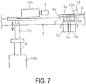
- the measuring device 1 of another embodiment illustrated in FIG. 7 has the same configuration as embodiments described above, except that a vertical movement mechanism 10c is additionally provided.
- the vertical movement mechanism 10c is configured to move the two-dimensional sensor 8 in the vertical direction.
- a hydraulic cylinder and the like can be used as the vertical movement mechanism 10c.
- the two-dimensional sensor 8 Before the inner circumferential length L is measured, the two-dimensional sensor 8 is positioned at a position facing the inner circumferential surface 12a of the circular member 12 by the vertical movement mechanism 10c. In this way, the two-dimensional sensor 8 positioned at a predetermined measurement position is rotated about the rotation shaft 9, the separation distance d from the two-dimensional sensor 8 to the inner circumferential surface 12a is measured, and the separation distances d for the entire circumference of the circular member 12 is measured.
- the method of calculating the inner circumferential length L of the circular member 12 is similar to that of the other embodiments.
- This embodiment allows the two-dimensional sensor 8 to be accurately positioned at a desired position according to the vertical position of the inner circumferential surface 12a.
- the two-dimensional sensor 8 may be moved to a position lower than the surface of the support 4 or the surface of the frame 2 and held there. This allows trouble to be avoided such as the circular member 12 or other members colliding with the two-dimensional sensor 8 during placement causing damage.
Landscapes
- Physics & Mathematics (AREA)
- General Physics & Mathematics (AREA)
- Life Sciences & Earth Sciences (AREA)
- General Life Sciences & Earth Sciences (AREA)
- Length Measuring Devices With Unspecified Measuring Means (AREA)
- Length Measuring Devices By Optical Means (AREA)
Abstract
Description
- The present invention relates to an inner circumferential length measuring device for a circular member and particularly relates to an inner circumferential length measuring device for a circular member capable of accurately measuring an inner circumferential length without applying an unnecessary load on the circular member.
- Various circular members (circular members and annular members) such as bead members and cylindrical rubber members are used in the manufacture of a rubber product such as a tire. The inner circumferential length of such a circular member has a preset setting value designated by the design. However, due to a manufacturing error or the like, the actual inner circumferential length of the circular member may differ from the preset setting value. If this deviation is within a tolerance range, there is no problem. However, if outside of this tolerance range, the rubber product manufactured using the circular member may have quality problems. Thus, the inner circumferential length of the circular member needs to be measured and determined.
- In the related art, various measuring devices for the inner circumferential length of an annular bead member have been proposed (for example, see
Patent Documents 1 and 2). In the device described inPatent Document 1, a cylindrical measurement support including two semicylindrical sections is disposed on the inner side of a bead member. In measuring the inner circumferential length of the bead member, the sections are moved away from each other and the outer circumferential surfaces of the sections are put in close contact with the inner circumferential surface of the bead member. The separation distance between the sections at this time and the circumferential length around the outer circumferential surfaces of the sections are used to measure the inner circumferential length of the bead member. However, because the outer circumferential surfaces of the sections are put in close contact with the inner circumferential surface of the bead member, force pushing to expand the diameter of the bead member is applied and this may cause deformation. Thus, this is not advantageous in improving the accuracy in measuring the inner circumferential length. - In the device described in
Patent Document 2, a roller is directly brought into contact and pushed against an inner circumferential surface of a bead member. The roller is rolled along the inner circumferential surface of the bead member for one rotation in the circumferential direction. The number of times the roller rotated is used to measure the inner circumferential length of the bead member. However, because the roller directly comes into contact and pushes against the inner circumferential surface of the bead member, deformation may occur. Thus, this is not advantageous in improving the accuracy in measuring the inner circumferential length. -
- Patent Document 1:
JP 2012-150013 A - Patent Document 2:
JP 06-1128 A - An object of the present invention is to provide an inner circumferential length measuring device for a circular member capable of accurately measuring an inner circumferential length without applying an unnecessary load of the circular member.
- To achieve the object described above, an inner circumferential length measuring device for a circular member according to an embodiment of the present invention includes:
- a support on which the circular member is placed;
- a two-dimensional sensor disposed allowing for movement relative to the support;
- a rotation driving mechanism configured to rotate the two-dimensional sensor; and
- a calculation unit configured to receive measurement data from the two-dimensional sensor;
- the two-dimensional sensor being disposed at a predetermined measurement position facing an inner circumferential surface of the circular member placed flat in an unrestrained state on the support;
- by the two-dimensional sensor being rotated about a predetermined position inward of the circular member via the rotation driving mechanism, a separation distance from the two-dimensional sensor to the inner circumferential surface being measured by the two-dimensional sensor in a non-contact state with the circular member in a range of an entire circumference of the circular member; and
- the calculation unit calculating an inner circumferential length of the circular member based on the separation distance measured and a distance from the predetermined position to the two-dimensional sensor in a plan view.
- According to an embodiment of the present invention, the inner circumferential length of the circular member placed flat in an unrestrained state on the support is measured using the two-dimensional sensor without the two-dimensional sensor coming into contact with the circular member. Thus, an unnecessary load is not applied to the circular member, and thus deformation thought obligatory does not occur. This is advantageous in measuring the inner circumferential length of the circular member with high accuracy.
-
- FIG. 1
- is an explanatory diagram illustrating an inner circumferential length measuring device of an embodiment of the present invention in a plan view.
- FIG. 2
- is an explanatory diagram illustrating the measuring device of
FIG. 1 in a side view. - FIG. 3
- is an explanatory diagram illustrating a support of the measuring device of
FIG. 2 in an upright position in a side view. - FIG. 4
- is an explanatory diagram illustrating a process of a two-dimensional sensor measuring a separation distance to an inner circumferential surface of a circular member.
- FIG. 5
- is an explanatory diagram illustrating the process of
FIG. 4 in a side view. - FIG. 6
- is an explanatory diagram illustrating a method of calculating an inner circumferential length.
- FIG. 7
- is an explanatory diagram illustrating, in a side view, the area around a two-dimensional sensor of a measuring device according to another embodiment.
- An inner circumferential length measuring device for a circular member according to embodiments of the present invention will be described in detail below with reference to embodiments illustrated in the drawings.
- Using an inner circumferential length measuring device for a circular member of an embodiment of the present invention illustrated in
FIGS. 1 and2 , the inner circumferential length can be measured for various circular members 12 (circular members and annular members) such as bead members and cylindrical rubber members used in a rubber product such as a tire. InFIG. 1 , thecircular member 12 is indicated by a two-dot chain line. When measuring, a singlecircular member 12 is set in themeasuring device 1. - The
measuring device 1 includes asupport 4 on which thecircular member 12 to be measured is placed, a two-dimensional sensor 8 disposed allowing for movement independent of thesupport 4, arotation driving mechanism 10a configured to rotate the two-dimensional sensor 8, and acalculation unit 11 configured to receive measurement data from the two-dimensional sensor 8. As thecalculation unit 11, various kinds of computers can be used. - The
circular member 12 is placed flat in an unrestrained state on the horizontally orientatedsupport 4. "Unrestrained state" is a state in which no external forces other than those relating gravitational forces (empty weight) are acting upon thecircular member 12. In this embodiment, thesupport 4 includes a plurality ofsections 5 divided in the circumferential direction. Eachsection 5 includes on an upper surface a protrusion-like support portion 6 that projects upward. Thecircular member 12 is placed flat in an unrestrained state on the protrusion-like support portions 6. The protrusion-like support portion 6 extends in a rod-like manner in the radial direction of thecircular member 12. - The
support 4 may be formed as an undivided single plate body instead of including thesections 5. The number of protrusion-like support portions 6 is at least three, with a suitable number ranging from three to twelve, for example. - The
support 4 is attached to aframe 2. Theframe 2 includes abase frame 2a and amovable frame 2b, and themovable frame 2b is connected to thebase frame 2a at one end in a manner allowing for rotation. Themovable frame 2b is able to be raised off thebase frame 2a via araising mechanism 3. For example, as illustrated inFIG. 3 , themovable frame 2b is raised a predetermined angle range from a horizontal state to a vertical state, taking an upright state. Accordingly, thesupport 4 also can be raised from a horizontal state to an upright state. A hydraulic cylinder or the like can be used as theraising mechanism 3. - A plurality of
projection portions 7 are provided on the surface of thesupport 4 spaced from one another, theprojection portions 7 projecting from the surface. Theprojection portions 7 are moved via aretracting mechanism 7a allowing them to retract from the surface of thesupport 4. An air cylinder, a hydraulic cylinder, and the like can be used as theretracting mechanism 7a. Twoprojection portions 7 work as a set, and the space between and position of theprojection portions 7 of a set in a plan view is set based on the inner diameter of thecircular member 12 to be measured. - The two-
dimensional sensor 8, in a plan view, is disposed in a central portion of thesupport 4 and disposed inward of thecircular member 12 placed flat on thesupport 4. The two-dimensional sensor 8 is capable of movement in the radial direction of thecircular member 12 via ahorizontal movement mechanism 10b. This allows the two-dimensional sensor 8 disposed facing an innercircumferential surface 12a of thecircular member 12 placed flat to be moved in the direction toward the innercircumferential surface 12a and away from the innercircumferential surface 12a. - The two-
dimensional sensor 8 and thehorizontal movement mechanism 10b, in a plan view, are disposed at a predetermined position on the support 4 (for example, the center of the support 4) and are supported by arotation shaft 9 configured to extend and retract vertically. Therotation shaft 9 is driven in rotation by therotation driving mechanism 10a about the axial center thereof. Accordingly, the two-dimensional sensor 8 is driven in rotation about therotation shaft 9. - A laser sensor can be used as the two-
dimensional sensor 8. The two-dimensional sensor 8 is configured to measure a separation distance d from the two-dimensional sensor 8 to the innercircumferential surface 12a in a non-contact state with thecircular member 12 by reflecting a laser beam of the innercircumferential surface 12a and receiving the reflected laser beam. The two-dimensional sensor 8 is configured to measure the separation distance d from the two-dimensional sensor 8 and the innercircumferential surface 12a in the range irradiated by radiating a laser beam not at one point of the innercircumferential surface 12a but in a single instance radiating a lengthwise area. - The separation distance d measured by the two-
dimensional sensor 8 is entered into thecalculation unit 11. Additionally, a distance w from the position of the rotation shaft 9 (axial center) to the two-dimensional sensor 8 in a plan view is entered into thecalculation unit 11. - The process of measuring an inner circumferential length L of the
circular member 12 using themeasuring device 1 will be described below. - To place the
circular member 12 flat on thesupport 4, firstly, thesupport 4 is put in an upright state at a predetermined angle as illustrated inFIG. 3 . Then, two of theprojection portions 7 chosen based on the inner diameter of thecircular member 12 are made to project from the surface of thesupport 4. The inclination angle of thesupport 4 in an upright state with respect to the horizontal ranges from 45° to 75°. - Next, the
circular member 12 is placed on thesupport 4 with the innercircumferential surface 12a of thecircular member 12 engaging with the twoprojection portions 7 projecting from the surface of thesupport 4. Accordingly, thecircular member 12 is put in a state in which the innercircumferential surface 12a is supported by the twoprojection portions 7 and alower surface 12b is supported by the protrusion-like support portions 6. A crane or the like can be used to place large-sizedcircular members 12. - Next, as illustrated in
FIG. 2 , thesupport 4 is lowered to a horizontal state by theraising mechanism 3. Thereafter, theprojection portions 7 are retracted under the surface of thesupport 4. This puts thecircular member 12 flat on thesupport 4 in an unrestrained state. - By placing the
circular member 12 on thesupport 4 in an upright state in such a manner, large-sized and heavycircular member 12 can be placed on thesupport 4 in a relatively small space. The inner diameter of thecircular member 12 measured as the inner circumferential length L is not particularly limited in the present invention, and, for example, the inner diameter in embodiments of the present invention can range from 500 mm to 2000 mm. By the inner circumferential surface of thecircular member 12 engaging with the twoprojection portions 7 on thesupport 4 in an upright state, thecircular member 12 can be positioned on thesupport 4. - Additionally, when the
support 4 in an upright state is brought to a horizontal state, thecircular member 12 is placed flat, positioned at a desired position with respect to thesupport 4. Accordingly, the positions of theprojection portions 7 are set on thesupport 4 at positions in a plan view where thecircular member 12 can be positioned at desired position when placed flat. For example, the positions of theprojection portions 7 are set on thesupport 4 at positions in a plan view such that the position of the center of the circle of thecircular member 12 when placed flat is in a range equal to or less than 20 mm out from the position of therotation shaft 9. Additionally, a suitable space between theprojection portions 7 is ensured, as when the space in a plan view between the twoprojection portions 7 that work as a set is too small, thesupport 4 in an upright state is unsuitable to stably hold thecircular member 12. - With different
circular members 12 of different inner diameters, the positions of theprojection portions 7 can change so that thecircular member 12 is positioned at a desired position when placed flat. For example, the twoprojection portions 7 are preferably set at suitable positions and a suitable space in a plan view to correspond to each size of the inner diameters of thecircular members 12. In this embodiment, by the positions of and space between the twoprojection portions 7 in a plan view being suitably set,circular members 12 of different inner diameter sizes can be set with the center of their circle when placed flat substantially coinciding with the position of therotation shaft 9. This allows variouscircular members 12 of various inner diameter sizes to be accurately position at a desired position on thesupport 4 and placed flat, granting high versatility. - Next, the two-
dimensional sensor 8 that faces the innercircumferential surface 12a of thecircular member 12 is moved as necessary by thehorizontal movement mechanism 10b toward the innercircumferential surface 12a and is stopped at a predetermined measurement position. In other words, the two-dimensional sensor 8 is moved such that the innercircumferential surface 12a is in a range enabling measurement by the two-dimensional sensor 8. Accordingly, in a case where the innercircumferential surface 12a of thecircular member 12 placed flat in an unrestrained state on thesupport 4 is in a range of the two-dimensional sensor 8 at its initial position enabling measurement, there is no need to move the two-dimensional sensor 8 via thehorizontal movement mechanism 10b. Thehorizontal movement mechanism 10b allows the two-dimensional sensor 8 to be easily set in a range enabling measurement of variouscircular members 12 of various inner diameter sizes. - Next, as illustrated in
FIGS. 4 and5 , the two-dimensional sensor 8 positioned at a predetermined measurement position is rotated about therotation shaft 9, the separation distance d from the two-dimensional sensor 8 to the innercircumferential surface 12a is measured, and the separation distances d for the entire circumference of thecircular member 12 is measured. The measured separation distances d are entered into thecalculation unit 11. The distance w in a plan view from therotation shaft 9 to the two-dimensional sensor 8 at a predetermined measurement position can be determined, and this distance w is also entered into thecalculation unit 11. Accordingly, a distance (w + d) from the axial center of therotation shaft 9 to the innercircumferential surface 12a in a plan view can be determined for the entire circumference of thecircular member 12. - The angle the two-
dimensional sensor 8 rotates about therotation shaft 9 between measuring the separation distance d at one position to measuring the separation distance d at the next position is a minute angle A (rad). For example, the minute angle A is approximately 2n/15000 (rad). - One example of the many possible methods of calculating the inner circumferential length L of the
circular member 12 will be described below. As illustrated inFIG. 6 , adopting the axial center of therotation shaft 9 as the origin point, a discretionary position P1 (X, Y) on the innercircumferential surface 12a of thecircular member 12 that is detected by the two-dimensional sensor 8 and a position P2 (x, y) that is the position P detected next are specified. The distance from the axial center of therotation shaft 9 to the position P1 in a plan view is w + d1 and the distance from the axial center of therotation shaft 9 to the position P2 is w + d2. The rotational angle from a reference point C to a position P1 is θ, and the coordinates for the position P1 (X, Y) are X = (w + d1)cosθ, and Y = (w + d1)sinθ. The coordinates for the position P2 (x, y) are x = (w + d2)cosθ(θ + A), and y = (w + d2)sinθ(θ + A). The coordinates of the reference point C, the rotational angle θ, the minute angle A, the distance (w + d1) and (w + d2) can be determined, thus the coordinates of the position P1 (X, Y) and the position P2 (x, y) can be found. A minute inner circumferential length L1 for the minute angle A can be approximated to L1 = {(X - x)2 + (Y - y)2}1/2. Thecalculation unit 11 calculates the inner circumferential length L by adding together the minute inner circumferential lengths L1 for the entire circumference of thecircular member 12. Note that inFIG. 6 , the angle is illustrated larger than the actual angle for the sake of describing the minute angle A. - The two-
dimensional sensor 8 in one instance radiates laser beams in a predetermined lengthwise range in the vertical direction and measures the separation distance d from the two-dimensional sensor 8 and the innercircumferential surface 12a in the irradiated range. As the separation distance d obtained when calculating the inner circumferential length L, for example, the separation distance d at a discretionary position in the vertical direction, such as the separation distance d at a center position of the innercircumferential surface 12a in the vertical direction, and the separation distance d at a predetermined position in the vertical direction, can be used. - According to the embodiment described above, the inner circumferential length L of the
circular member 12 placed flat in an unrestrained state on thesupport 4 is measured using the two-dimensional sensor 8 in a non-contact state with thecircular member 12. Thus, an unnecessary load is not applied to thecircular member 12, and thus deformation thought obligatory does not occur. This is advantageous in measuring the inner circumferential length L of thecircular member 12 with high accuracy. - In this embodiment, the surface of an adjacent portion of the
support 4 adjacent to thecircular member 12 placed flat on thesupport 4 in an unrestrained state includes alow reflection surface 6a configured to diffuse reflect the laser beam radiated from the two-dimensional sensor 8. Specifically, the upper surface and the inner circumferential end surface of the protrusion-like support portion 6 are low reflection surfaces 6a blast treated to form minute ridges/grooves in the surface. In this way, a laser beam that hits the upper surface or the inner circumferential end surface of the protrusion-like support portion 6 is diffuse reflected and is not received by the two-dimensional sensor 8. Thus, in a configuration in which the two-dimensional sensor 8 is configured to radiate a laser beam in an area rather than at a single point, measurement noise when measuring the separation distance d can be reduced. - The
projection portions 7 are retracted below the surface of thesupport 4 when the two-dimensional sensor 8 measures the separation distance d. Thus, theprojection portions 7 do not block the laser beam radiated from the two-dimensional sensor 8. - Additionally, the
circular member 12 is supported by the protrusion-like support portions 6, making it easy to align the measurement center of the two-dimensional sensor 8 and the center of the innercircumferential surface 12a of thecircular member 12 in the vertical direction. Furthermore, the innercircumferential surface 12a is suspended at the portions where thecircular member 12 is not supported by the protrusion-like support portions 6. Thus, the adjacent portions of thesupport 4 adjacent to the innercircumferential surface 12a are kept to a minimum. This is advantageous in reducing measurement noise when measuring the separation distance d via the two-dimensional sensor 8. - The
support 4 may be unable to be raised and be only used in a horizontal state. In this configuration, thesupport 4 is installed on the horizontally fixed upper surface (framework) of theframe 2. Thecircular member 12 is placed on thesupport 4 in a laid down state. A crane or the like can be used to hoist a large-sizedcircular member 12 in a laid down state and place it on thesupport 4. - The measuring
device 1 of another embodiment illustrated inFIG. 7 has the same configuration as embodiments described above, except that avertical movement mechanism 10c is additionally provided. Thevertical movement mechanism 10c is configured to move the two-dimensional sensor 8 in the vertical direction. - A hydraulic cylinder and the like can be used as the
vertical movement mechanism 10c. Before the inner circumferential length L is measured, the two-dimensional sensor 8 is positioned at a position facing the innercircumferential surface 12a of thecircular member 12 by thevertical movement mechanism 10c. In this way, the two-dimensional sensor 8 positioned at a predetermined measurement position is rotated about therotation shaft 9, the separation distance d from the two-dimensional sensor 8 to the innercircumferential surface 12a is measured, and the separation distances d for the entire circumference of thecircular member 12 is measured. The method of calculating the inner circumferential length L of thecircular member 12 is similar to that of the other embodiments. - This embodiment allows the two-
dimensional sensor 8 to be accurately positioned at a desired position according to the vertical position of the innercircumferential surface 12a. When not measuring, for example, the two-dimensional sensor 8 may be moved to a position lower than the surface of thesupport 4 or the surface of theframe 2 and held there. This allows trouble to be avoided such as thecircular member 12 or other members colliding with the two-dimensional sensor 8 during placement causing damage. -
- 1 Measuring device
- 2 Frame
- 2a Base frame
- 2b Movable frame
- 3 Raising mechanism
- 4 Support
- 5 Section
- 6 Protrusion-like support portion
- 6a Low reflection surface
- 7 Projection portion
- 7a Retracting mechanism
- 8 Two-dimensional sensor
- 9 Rotation shaft
- 10a Rotation driving mechanism
- 10b Horizontal movement mechanism
- 10c Vertical movement mechanism
- 11 Calculation unit
- 12 Circular member
- 12a Inner circumferential surface
- 12b Lower surface
Claims (3)
- An inner circumferential length measuring device for a circular member, comprising:a support on which the circular member is placed;a two-dimensional sensor disposed allowing for movement relative to the support;a rotation driving mechanism configured to rotate the two-dimensional sensor; anda calculation unit configured to receive measurement data from the two-dimensional sensor;the two-dimensional sensor being disposed at a predetermined measurement position facing an inner circumferential surface of the circular member placed flat in an unrestrained state on the support;
by the two-dimensional sensor being rotated about a predetermined position inward of the circular member via the rotation driving mechanism, a separation distance from the two-dimensional sensor to the inner circumferential surface being measured by the two-dimensional sensor in a non-contact state with the circular member in a range of an entire circumference of the circular member; and
the calculation unit calculating an inner circumferential length of the circular member based on the separation distance measured and a distance from the predetermined position to the two-dimensional sensor in a plan view. - The inner circumferential length measuring device for a circular member according to claim 1, further comprising
a horizontal movement mechanism configured to move the two-dimensional sensor in a horizontal direction, the horizontal movement mechanism positioning the two-dimensional sensor at the measurement position in a plan view. - The inner circumferential length measuring device for a circular member according to claim 1 or 2, further comprising
a vertical movement mechanism configured to move the two-dimensional sensor in a vertical direction, the vertical movement mechanism positioning the two-dimensional sensor at a position facing the inner circumferential surface.
Applications Claiming Priority (2)
| Application Number | Priority Date | Filing Date | Title |
|---|---|---|---|
| JP2016052614A JP6206527B2 (en) | 2016-03-16 | 2016-03-16 | Device for measuring the inner circumference of a circular member |
| PCT/JP2017/005615 WO2017159193A1 (en) | 2016-03-16 | 2017-02-16 | Internal circumference measurement device for circular member |
Publications (3)
| Publication Number | Publication Date |
|---|---|
| EP3431922A1 true EP3431922A1 (en) | 2019-01-23 |
| EP3431922A4 EP3431922A4 (en) | 2019-09-25 |
| EP3431922B1 EP3431922B1 (en) | 2022-03-02 |
Family
ID=59850217
Family Applications (1)
| Application Number | Title | Priority Date | Filing Date |
|---|---|---|---|
| EP17766200.4A Active EP3431922B1 (en) | 2016-03-16 | 2017-02-16 | Internal circumference measurement device for circular member |
Country Status (6)
| Country | Link |
|---|---|
| US (1) | US10775154B2 (en) |
| EP (1) | EP3431922B1 (en) |
| JP (1) | JP6206527B2 (en) |
| KR (1) | KR102067776B1 (en) |
| CN (1) | CN108603753B (en) |
| WO (1) | WO2017159193A1 (en) |
Families Citing this family (4)
| Publication number | Priority date | Publication date | Assignee | Title |
|---|---|---|---|---|
| JP6146505B1 (en) * | 2016-03-16 | 2017-06-14 | 横浜ゴム株式会社 | Device for measuring the inner circumference of a circular member |
| JP6233434B2 (en) * | 2016-03-16 | 2017-11-22 | 横浜ゴム株式会社 | Measuring method of inner circumference of circular member |
| US10845192B2 (en) * | 2017-09-13 | 2020-11-24 | Shawn Thomas Lause | Machine tool test fixture |
| CN109341622B (en) * | 2018-12-06 | 2020-10-02 | 燕山大学 | Contact type special vehicle supporting roller height detector |
Family Cites Families (25)
| Publication number | Priority date | Publication date | Assignee | Title |
|---|---|---|---|---|
| JPH01195309A (en) * | 1988-01-29 | 1989-08-07 | Sumitomo Rubber Ind Ltd | Measuring instrument for cylindrical body |
| JPH061128A (en) | 1992-06-23 | 1994-01-11 | Yokohama Rubber Co Ltd:The | Tire bead inside perimeter measuring instrument |
| JP2759055B2 (en) * | 1994-08-22 | 1998-05-28 | 川崎製鉄株式会社 | Automatic payoff reel deceleration control method |
| US6289600B1 (en) * | 1999-11-02 | 2001-09-18 | United States Pipe & Foundry Company | Non-contact measuring device |
| US7251580B2 (en) | 2003-10-20 | 2007-07-31 | Mitutoyo Corporation | Method for measuring curved surface of workpiece, program and medium thereof |
| JP4100330B2 (en) * | 2003-11-10 | 2008-06-11 | オムロン株式会社 | Thin film measuring method and thin film measuring apparatus |
| GB0605796D0 (en) | 2006-03-23 | 2006-05-03 | Renishaw Plc | Apparatus and method of measuring workpieces |
| JP5120625B2 (en) * | 2008-03-07 | 2013-01-16 | アイシン精機株式会社 | Inner surface measuring device |
| JP2010048731A (en) * | 2008-08-25 | 2010-03-04 | Toyota Motor Corp | Measuring device and measuring method of cross-sectional shape |
| JP5269698B2 (en) * | 2009-06-10 | 2013-08-21 | 株式会社ミツトヨ | Roundness measuring device |
| KR101118957B1 (en) * | 2009-12-29 | 2012-03-05 | 주식회사 성우하이텍 | Table jig for door sanding |
| JP2012150013A (en) | 2011-01-19 | 2012-08-09 | Sumitomo Rubber Ind Ltd | Inner circumferential length measurement device of bead core |
| CN202432959U (en) * | 2011-12-26 | 2012-09-12 | 宝山钢铁股份有限公司 | Multifunctional disc scissor blade detection rack |
| JP2013134176A (en) * | 2011-12-27 | 2013-07-08 | Sharp Corp | Imaging apparatus and imaging method |
| JP2013186009A (en) * | 2012-03-08 | 2013-09-19 | Toyota Motor Corp | Calibration method of shape measurement device |
| JP6169339B2 (en) * | 2012-10-04 | 2017-07-26 | 株式会社日立製作所 | Shape measuring method and apparatus |
| CN102980558A (en) * | 2012-12-07 | 2013-03-20 | 辽宁工程技术大学 | Intelligent tunnel section measurement device and method for mine based on polar coordinate integral |
| CN102997851B (en) * | 2012-12-11 | 2015-08-05 | 三一重工股份有限公司 | The circumference measuring method of spiral-tube and device for measuring circumference |
| CN104180763A (en) * | 2013-05-24 | 2014-12-03 | 南开大学 | Non-contact measurement apparatus of inner and outer diameters of large-diameter circular ring type component |
| CN103278100B (en) * | 2013-06-19 | 2016-06-22 | 天津大学 | A kind of bore diameter measuring method based on noncontacting proximity sensor combination |
| US10371507B2 (en) | 2013-07-19 | 2019-08-06 | Nikon Corporation | Shape measurement device, structural object production system, shape measurement method, structural object production method, shape measurement program, and recording medium |
| CN203615897U (en) * | 2013-09-23 | 2014-05-28 | 北京石油化工学院 | Pipeline internal diameter measure apparatus based on displacement sensor |
| CN204325905U (en) * | 2014-10-28 | 2015-05-13 | 中铁二院工程集团有限责任公司 | For the dynamometry elastic body of multidirectional dynamometry ball shaped steel bearing |
| JP6233434B2 (en) * | 2016-03-16 | 2017-11-22 | 横浜ゴム株式会社 | Measuring method of inner circumference of circular member |
| JP6146505B1 (en) * | 2016-03-16 | 2017-06-14 | 横浜ゴム株式会社 | Device for measuring the inner circumference of a circular member |
-
2016
- 2016-03-16 JP JP2016052614A patent/JP6206527B2/en active Active
-
2017
- 2017-02-16 US US16/085,561 patent/US10775154B2/en active Active
- 2017-02-16 EP EP17766200.4A patent/EP3431922B1/en active Active
- 2017-02-16 WO PCT/JP2017/005615 patent/WO2017159193A1/en not_active Ceased
- 2017-02-16 CN CN201780010562.6A patent/CN108603753B/en active Active
- 2017-02-16 KR KR1020187021217A patent/KR102067776B1/en active Active
Also Published As
| Publication number | Publication date |
|---|---|
| CN108603753A (en) | 2018-09-28 |
| EP3431922B1 (en) | 2022-03-02 |
| US20190154433A1 (en) | 2019-05-23 |
| KR102067776B1 (en) | 2020-02-11 |
| WO2017159193A1 (en) | 2017-09-21 |
| JP6206527B2 (en) | 2017-10-04 |
| KR20180098338A (en) | 2018-09-03 |
| JP2017166982A (en) | 2017-09-21 |
| CN108603753B (en) | 2020-08-04 |
| US10775154B2 (en) | 2020-09-15 |
| EP3431922A4 (en) | 2019-09-25 |
Similar Documents
| Publication | Publication Date | Title |
|---|---|---|
| EP3431922B1 (en) | Internal circumference measurement device for circular member | |
| EP3431924B1 (en) | Internal circumference measurement method for circular member | |
| EP3431923B1 (en) | Internal circumference measurement method for circular member | |
| CN106415197B (en) | Method for correcting surface shape data of annular rotating body and apparatus for inspecting appearance of annular rotating body | |
| JP6924953B2 (en) | Shape measuring device and shape measuring method | |
| CN110600413A (en) | Alignment device | |
| JP4499222B2 (en) | Inner diameter measuring device | |
| CN105353778A (en) | Automatic attitude adjusting device used for residual stress test | |
| EP2620825A1 (en) | Positioning system on a piece-holder table of a machine tool and method of positioning the piece on the table | |
| JP4622721B2 (en) | Tire balance measuring device and measuring method | |
| CN110274535B (en) | Outer ring detection device of outer spherical bearing | |
| US20210060883A1 (en) | Tire molding apparatus | |
| CN110102899B (en) | Processing device and processing method for cylindrical product with variable outer diameter | |
| JP2007261739A (en) | Position adjustment support device, position adjustment device, and position adjustment method for long heavy object | |
| KR102025399B1 (en) | Apparatus for transfering a object | |
| JP2009058394A (en) | Shape measuring device and shape measuring method | |
| CN110296678A (en) | A kind of hole coaxality measuring mechanism and its measurement method |
Legal Events
| Date | Code | Title | Description |
|---|---|---|---|
| STAA | Information on the status of an ep patent application or granted ep patent |
Free format text: STATUS: THE INTERNATIONAL PUBLICATION HAS BEEN MADE |
|
| PUAI | Public reference made under article 153(3) epc to a published international application that has entered the european phase |
Free format text: ORIGINAL CODE: 0009012 |
|
| STAA | Information on the status of an ep patent application or granted ep patent |
Free format text: STATUS: REQUEST FOR EXAMINATION WAS MADE |
|
| 17P | Request for examination filed |
Effective date: 20180810 |
|
| AK | Designated contracting states |
Kind code of ref document: A1 Designated state(s): AL AT BE BG CH CY CZ DE DK EE ES FI FR GB GR HR HU IE IS IT LI LT LU LV MC MK MT NL NO PL PT RO RS SE SI SK SM TR |
|
| AX | Request for extension of the european patent |
Extension state: BA ME |
|
| DAV | Request for validation of the european patent (deleted) | ||
| DAX | Request for extension of the european patent (deleted) | ||
| A4 | Supplementary search report drawn up and despatched |
Effective date: 20190828 |
|
| RIC1 | Information provided on ipc code assigned before grant |
Ipc: G01B 21/20 20060101ALI20190822BHEP Ipc: G01B 11/12 20060101ALI20190822BHEP Ipc: G01B 11/255 20060101ALI20190822BHEP Ipc: G01B 21/14 20060101ALI20190822BHEP Ipc: G01B 21/02 20060101AFI20190822BHEP Ipc: G01B 11/24 20060101ALI20190822BHEP Ipc: G01B 11/02 20060101ALI20190822BHEP Ipc: G01B 11/04 20060101ALI20190822BHEP |
|
| GRAP | Despatch of communication of intention to grant a patent |
Free format text: ORIGINAL CODE: EPIDOSNIGR1 |
|
| STAA | Information on the status of an ep patent application or granted ep patent |
Free format text: STATUS: GRANT OF PATENT IS INTENDED |
|
| INTG | Intention to grant announced |
Effective date: 20211109 |
|
| GRAS | Grant fee paid |
Free format text: ORIGINAL CODE: EPIDOSNIGR3 |
|
| GRAA | (expected) grant |
Free format text: ORIGINAL CODE: 0009210 |
|
| STAA | Information on the status of an ep patent application or granted ep patent |
Free format text: STATUS: THE PATENT HAS BEEN GRANTED |
|
| AK | Designated contracting states |
Kind code of ref document: B1 Designated state(s): AL AT BE BG CH CY CZ DE DK EE ES FI FR GB GR HR HU IE IS IT LI LT LU LV MC MK MT NL NO PL PT RO RS SE SI SK SM TR |
|
| REG | Reference to a national code |
Ref country code: GB Ref legal event code: FG4D |
|
| REG | Reference to a national code |
Ref country code: CH Ref legal event code: EP Ref country code: AT Ref legal event code: REF Ref document number: 1472591 Country of ref document: AT Kind code of ref document: T Effective date: 20220315 |
|
| REG | Reference to a national code |
Ref country code: DE Ref legal event code: R096 Ref document number: 602017054078 Country of ref document: DE |
|
| REG | Reference to a national code |
Ref country code: IE Ref legal event code: FG4D |
|
| REG | Reference to a national code |
Ref country code: LT Ref legal event code: MG9D |
|
| REG | Reference to a national code |
Ref country code: NL Ref legal event code: MP Effective date: 20220302 |
|
| PG25 | Lapsed in a contracting state [announced via postgrant information from national office to epo] |
Ref country code: SE Free format text: LAPSE BECAUSE OF FAILURE TO SUBMIT A TRANSLATION OF THE DESCRIPTION OR TO PAY THE FEE WITHIN THE PRESCRIBED TIME-LIMIT Effective date: 20220302 Ref country code: RS Free format text: LAPSE BECAUSE OF FAILURE TO SUBMIT A TRANSLATION OF THE DESCRIPTION OR TO PAY THE FEE WITHIN THE PRESCRIBED TIME-LIMIT Effective date: 20220302 Ref country code: NO Free format text: LAPSE BECAUSE OF FAILURE TO SUBMIT A TRANSLATION OF THE DESCRIPTION OR TO PAY THE FEE WITHIN THE PRESCRIBED TIME-LIMIT Effective date: 20220602 Ref country code: LT Free format text: LAPSE BECAUSE OF FAILURE TO SUBMIT A TRANSLATION OF THE DESCRIPTION OR TO PAY THE FEE WITHIN THE PRESCRIBED TIME-LIMIT Effective date: 20220302 Ref country code: HR Free format text: LAPSE BECAUSE OF FAILURE TO SUBMIT A TRANSLATION OF THE DESCRIPTION OR TO PAY THE FEE WITHIN THE PRESCRIBED TIME-LIMIT Effective date: 20220302 Ref country code: ES Free format text: LAPSE BECAUSE OF FAILURE TO SUBMIT A TRANSLATION OF THE DESCRIPTION OR TO PAY THE FEE WITHIN THE PRESCRIBED TIME-LIMIT Effective date: 20220302 Ref country code: BG Free format text: LAPSE BECAUSE OF FAILURE TO SUBMIT A TRANSLATION OF THE DESCRIPTION OR TO PAY THE FEE WITHIN THE PRESCRIBED TIME-LIMIT Effective date: 20220602 |
|
| REG | Reference to a national code |
Ref country code: AT Ref legal event code: MK05 Ref document number: 1472591 Country of ref document: AT Kind code of ref document: T Effective date: 20220302 |
|
| PG25 | Lapsed in a contracting state [announced via postgrant information from national office to epo] |
Ref country code: PL Free format text: LAPSE BECAUSE OF FAILURE TO SUBMIT A TRANSLATION OF THE DESCRIPTION OR TO PAY THE FEE WITHIN THE PRESCRIBED TIME-LIMIT Effective date: 20220302 Ref country code: LV Free format text: LAPSE BECAUSE OF FAILURE TO SUBMIT A TRANSLATION OF THE DESCRIPTION OR TO PAY THE FEE WITHIN THE PRESCRIBED TIME-LIMIT Effective date: 20220302 Ref country code: GR Free format text: LAPSE BECAUSE OF FAILURE TO SUBMIT A TRANSLATION OF THE DESCRIPTION OR TO PAY THE FEE WITHIN THE PRESCRIBED TIME-LIMIT Effective date: 20220603 Ref country code: FI Free format text: LAPSE BECAUSE OF FAILURE TO SUBMIT A TRANSLATION OF THE DESCRIPTION OR TO PAY THE FEE WITHIN THE PRESCRIBED TIME-LIMIT Effective date: 20220302 |
|
| PG25 | Lapsed in a contracting state [announced via postgrant information from national office to epo] |
Ref country code: NL Free format text: LAPSE BECAUSE OF FAILURE TO SUBMIT A TRANSLATION OF THE DESCRIPTION OR TO PAY THE FEE WITHIN THE PRESCRIBED TIME-LIMIT Effective date: 20220302 |
|
| PG25 | Lapsed in a contracting state [announced via postgrant information from national office to epo] |
Ref country code: SM Free format text: LAPSE BECAUSE OF FAILURE TO SUBMIT A TRANSLATION OF THE DESCRIPTION OR TO PAY THE FEE WITHIN THE PRESCRIBED TIME-LIMIT Effective date: 20220302 Ref country code: SK Free format text: LAPSE BECAUSE OF FAILURE TO SUBMIT A TRANSLATION OF THE DESCRIPTION OR TO PAY THE FEE WITHIN THE PRESCRIBED TIME-LIMIT Effective date: 20220302 Ref country code: RO Free format text: LAPSE BECAUSE OF FAILURE TO SUBMIT A TRANSLATION OF THE DESCRIPTION OR TO PAY THE FEE WITHIN THE PRESCRIBED TIME-LIMIT Effective date: 20220302 Ref country code: PT Free format text: LAPSE BECAUSE OF FAILURE TO SUBMIT A TRANSLATION OF THE DESCRIPTION OR TO PAY THE FEE WITHIN THE PRESCRIBED TIME-LIMIT Effective date: 20220704 Ref country code: EE Free format text: LAPSE BECAUSE OF FAILURE TO SUBMIT A TRANSLATION OF THE DESCRIPTION OR TO PAY THE FEE WITHIN THE PRESCRIBED TIME-LIMIT Effective date: 20220302 Ref country code: CZ Free format text: LAPSE BECAUSE OF FAILURE TO SUBMIT A TRANSLATION OF THE DESCRIPTION OR TO PAY THE FEE WITHIN THE PRESCRIBED TIME-LIMIT Effective date: 20220302 Ref country code: AT Free format text: LAPSE BECAUSE OF FAILURE TO SUBMIT A TRANSLATION OF THE DESCRIPTION OR TO PAY THE FEE WITHIN THE PRESCRIBED TIME-LIMIT Effective date: 20220302 |
|
| PG25 | Lapsed in a contracting state [announced via postgrant information from national office to epo] |
Ref country code: IS Free format text: LAPSE BECAUSE OF FAILURE TO SUBMIT A TRANSLATION OF THE DESCRIPTION OR TO PAY THE FEE WITHIN THE PRESCRIBED TIME-LIMIT Effective date: 20220702 Ref country code: AL Free format text: LAPSE BECAUSE OF FAILURE TO SUBMIT A TRANSLATION OF THE DESCRIPTION OR TO PAY THE FEE WITHIN THE PRESCRIBED TIME-LIMIT Effective date: 20220302 |
|
| REG | Reference to a national code |
Ref country code: DE Ref legal event code: R097 Ref document number: 602017054078 Country of ref document: DE |
|
| PLBE | No opposition filed within time limit |
Free format text: ORIGINAL CODE: 0009261 |
|
| STAA | Information on the status of an ep patent application or granted ep patent |
Free format text: STATUS: NO OPPOSITION FILED WITHIN TIME LIMIT |
|
| PG25 | Lapsed in a contracting state [announced via postgrant information from national office to epo] |
Ref country code: DK Free format text: LAPSE BECAUSE OF FAILURE TO SUBMIT A TRANSLATION OF THE DESCRIPTION OR TO PAY THE FEE WITHIN THE PRESCRIBED TIME-LIMIT Effective date: 20220302 |
|
| 26N | No opposition filed |
Effective date: 20221205 |
|
| PG25 | Lapsed in a contracting state [announced via postgrant information from national office to epo] |
Ref country code: SI Free format text: LAPSE BECAUSE OF FAILURE TO SUBMIT A TRANSLATION OF THE DESCRIPTION OR TO PAY THE FEE WITHIN THE PRESCRIBED TIME-LIMIT Effective date: 20220302 |
|
| P01 | Opt-out of the competence of the unified patent court (upc) registered |
Effective date: 20230512 |
|
| PG25 | Lapsed in a contracting state [announced via postgrant information from national office to epo] |
Ref country code: IT Free format text: LAPSE BECAUSE OF FAILURE TO SUBMIT A TRANSLATION OF THE DESCRIPTION OR TO PAY THE FEE WITHIN THE PRESCRIBED TIME-LIMIT Effective date: 20220302 |
|
| PG25 | Lapsed in a contracting state [announced via postgrant information from national office to epo] |
Ref country code: MC Free format text: LAPSE BECAUSE OF FAILURE TO SUBMIT A TRANSLATION OF THE DESCRIPTION OR TO PAY THE FEE WITHIN THE PRESCRIBED TIME-LIMIT Effective date: 20220302 |
|
| REG | Reference to a national code |
Ref country code: CH Ref legal event code: PL |
|
| REG | Reference to a national code |
Ref country code: BE Ref legal event code: MM Effective date: 20230228 |
|
| GBPC | Gb: european patent ceased through non-payment of renewal fee |
Effective date: 20230216 |
|
| PG25 | Lapsed in a contracting state [announced via postgrant information from national office to epo] |
Ref country code: LU Free format text: LAPSE BECAUSE OF NON-PAYMENT OF DUE FEES Effective date: 20230216 Ref country code: LI Free format text: LAPSE BECAUSE OF NON-PAYMENT OF DUE FEES Effective date: 20230228 Ref country code: CH Free format text: LAPSE BECAUSE OF NON-PAYMENT OF DUE FEES Effective date: 20230228 |
|
| REG | Reference to a national code |
Ref country code: IE Ref legal event code: MM4A |
|
| PG25 | Lapsed in a contracting state [announced via postgrant information from national office to epo] |
Ref country code: GB Free format text: LAPSE BECAUSE OF NON-PAYMENT OF DUE FEES Effective date: 20230216 |
|
| PG25 | Lapsed in a contracting state [announced via postgrant information from national office to epo] |
Ref country code: IE Free format text: LAPSE BECAUSE OF NON-PAYMENT OF DUE FEES Effective date: 20230216 Ref country code: GB Free format text: LAPSE BECAUSE OF NON-PAYMENT OF DUE FEES Effective date: 20230216 |
|
| PG25 | Lapsed in a contracting state [announced via postgrant information from national office to epo] |
Ref country code: BE Free format text: LAPSE BECAUSE OF NON-PAYMENT OF DUE FEES Effective date: 20230228 |
|
| PG25 | Lapsed in a contracting state [announced via postgrant information from national office to epo] |
Ref country code: CY Free format text: LAPSE BECAUSE OF FAILURE TO SUBMIT A TRANSLATION OF THE DESCRIPTION OR TO PAY THE FEE WITHIN THE PRESCRIBED TIME-LIMIT; INVALID AB INITIO Effective date: 20170216 |
|
| PG25 | Lapsed in a contracting state [announced via postgrant information from national office to epo] |
Ref country code: HU Free format text: LAPSE BECAUSE OF FAILURE TO SUBMIT A TRANSLATION OF THE DESCRIPTION OR TO PAY THE FEE WITHIN THE PRESCRIBED TIME-LIMIT; INVALID AB INITIO Effective date: 20170216 |
|
| PG25 | Lapsed in a contracting state [announced via postgrant information from national office to epo] |
Ref country code: TR Free format text: LAPSE BECAUSE OF FAILURE TO SUBMIT A TRANSLATION OF THE DESCRIPTION OR TO PAY THE FEE WITHIN THE PRESCRIBED TIME-LIMIT Effective date: 20220302 |
|
| PGFP | Annual fee paid to national office [announced via postgrant information from national office to epo] |
Ref country code: FR Payment date: 20251231 Year of fee payment: 10 |
|
| PGFP | Annual fee paid to national office [announced via postgrant information from national office to epo] |
Ref country code: DE Payment date: 20251230 Year of fee payment: 10 |