EP3431750A1 - Procédé de détermination de la position d'agencement d'un générateur de vortex sur une pale de turbine éolienne, procédé de fabrication d'un ensemble de pales de turbine éolienne et ensemble de pales de turbine éolienne - Google Patents
Procédé de détermination de la position d'agencement d'un générateur de vortex sur une pale de turbine éolienne, procédé de fabrication d'un ensemble de pales de turbine éolienne et ensemble de pales de turbine éolienne Download PDFInfo
- Publication number
- EP3431750A1 EP3431750A1 EP18171891.7A EP18171891A EP3431750A1 EP 3431750 A1 EP3431750 A1 EP 3431750A1 EP 18171891 A EP18171891 A EP 18171891A EP 3431750 A1 EP3431750 A1 EP 3431750A1
- Authority
- EP
- European Patent Office
- Prior art keywords
- wind turbine
- vortex generator
- turbine blade
- blade
- region
- Prior art date
- Legal status (The legal status is an assumption and is not a legal conclusion. Google has not performed a legal analysis and makes no representation as to the accuracy of the status listed.)
- Granted
Links
- 238000000034 method Methods 0.000 title claims abstract description 64
- 238000004519 manufacturing process Methods 0.000 title claims description 7
- 238000000926 separation method Methods 0.000 claims abstract description 54
- 230000007704 transition Effects 0.000 claims abstract description 42
- 238000004364 calculation method Methods 0.000 claims description 14
- 230000015556 catabolic process Effects 0.000 description 23
- 238000006731 degradation reaction Methods 0.000 description 23
- 230000000694 effects Effects 0.000 description 18
- 238000011144 upstream manufacturing Methods 0.000 description 13
- 239000013598 vector Substances 0.000 description 12
- 238000004458 analytical method Methods 0.000 description 10
- 230000003993 interaction Effects 0.000 description 7
- 238000010586 diagram Methods 0.000 description 6
- 230000000712 assembly Effects 0.000 description 5
- 238000000429 assembly Methods 0.000 description 5
- 230000007423 decrease Effects 0.000 description 4
- 238000005452 bending Methods 0.000 description 3
- 230000035882 stress Effects 0.000 description 3
- 238000013459 approach Methods 0.000 description 2
- 230000008901 benefit Effects 0.000 description 2
- 238000009434 installation Methods 0.000 description 2
- 230000032683 aging Effects 0.000 description 1
- 230000008859 change Effects 0.000 description 1
- 239000000463 material Substances 0.000 description 1
- 230000004044 response Effects 0.000 description 1
- XLYOFNOQVPJJNP-UHFFFAOYSA-N water Substances O XLYOFNOQVPJJNP-UHFFFAOYSA-N 0.000 description 1
Images


Classifications
-
- F—MECHANICAL ENGINEERING; LIGHTING; HEATING; WEAPONS; BLASTING
- F03—MACHINES OR ENGINES FOR LIQUIDS; WIND, SPRING, OR WEIGHT MOTORS; PRODUCING MECHANICAL POWER OR A REACTIVE PROPULSIVE THRUST, NOT OTHERWISE PROVIDED FOR
- F03D—WIND MOTORS
- F03D1/00—Wind motors with rotation axis substantially parallel to the air flow entering the rotor
- F03D1/06—Rotors
- F03D1/0608—Rotors characterised by their aerodynamic shape
- F03D1/0633—Rotors characterised by their aerodynamic shape of the blades
- F03D1/0641—Rotors characterised by their aerodynamic shape of the blades of the section profile of the blades, i.e. aerofoil profile
-
- F—MECHANICAL ENGINEERING; LIGHTING; HEATING; WEAPONS; BLASTING
- F03—MACHINES OR ENGINES FOR LIQUIDS; WIND, SPRING, OR WEIGHT MOTORS; PRODUCING MECHANICAL POWER OR A REACTIVE PROPULSIVE THRUST, NOT OTHERWISE PROVIDED FOR
- F03D—WIND MOTORS
- F03D1/00—Wind motors with rotation axis substantially parallel to the air flow entering the rotor
- F03D1/06—Rotors
- F03D1/065—Rotors characterised by their construction elements
- F03D1/0675—Rotors characterised by their construction elements of the blades
-
- F—MECHANICAL ENGINEERING; LIGHTING; HEATING; WEAPONS; BLASTING
- F05—INDEXING SCHEMES RELATING TO ENGINES OR PUMPS IN VARIOUS SUBCLASSES OF CLASSES F01-F04
- F05B—INDEXING SCHEME RELATING TO WIND, SPRING, WEIGHT, INERTIA OR LIKE MOTORS, TO MACHINES OR ENGINES FOR LIQUIDS COVERED BY SUBCLASSES F03B, F03D AND F03G
- F05B2220/00—Application
- F05B2220/70—Application in combination with
- F05B2220/706—Application in combination with an electrical generator
-
- F—MECHANICAL ENGINEERING; LIGHTING; HEATING; WEAPONS; BLASTING
- F05—INDEXING SCHEMES RELATING TO ENGINES OR PUMPS IN VARIOUS SUBCLASSES OF CLASSES F01-F04
- F05B—INDEXING SCHEME RELATING TO WIND, SPRING, WEIGHT, INERTIA OR LIKE MOTORS, TO MACHINES OR ENGINES FOR LIQUIDS COVERED BY SUBCLASSES F03B, F03D AND F03G
- F05B2230/00—Manufacture
- F05B2230/60—Assembly methods
-
- F—MECHANICAL ENGINEERING; LIGHTING; HEATING; WEAPONS; BLASTING
- F05—INDEXING SCHEMES RELATING TO ENGINES OR PUMPS IN VARIOUS SUBCLASSES OF CLASSES F01-F04
- F05B—INDEXING SCHEME RELATING TO WIND, SPRING, WEIGHT, INERTIA OR LIKE MOTORS, TO MACHINES OR ENGINES FOR LIQUIDS COVERED BY SUBCLASSES F03B, F03D AND F03G
- F05B2240/00—Components
- F05B2240/20—Rotors
- F05B2240/21—Rotors for wind turbines
- F05B2240/221—Rotors for wind turbines with horizontal axis
- F05B2240/2211—Rotors for wind turbines with horizontal axis of the multibladed, low speed, e.g. "American farm" type
-
- F—MECHANICAL ENGINEERING; LIGHTING; HEATING; WEAPONS; BLASTING
- F05—INDEXING SCHEMES RELATING TO ENGINES OR PUMPS IN VARIOUS SUBCLASSES OF CLASSES F01-F04
- F05B—INDEXING SCHEME RELATING TO WIND, SPRING, WEIGHT, INERTIA OR LIKE MOTORS, TO MACHINES OR ENGINES FOR LIQUIDS COVERED BY SUBCLASSES F03B, F03D AND F03G
- F05B2240/00—Components
- F05B2240/20—Rotors
- F05B2240/30—Characteristics of rotor blades, i.e. of any element transforming dynamic fluid energy to or from rotational energy and being attached to a rotor
- F05B2240/306—Surface measures
- F05B2240/3062—Vortex generators
-
- Y—GENERAL TAGGING OF NEW TECHNOLOGICAL DEVELOPMENTS; GENERAL TAGGING OF CROSS-SECTIONAL TECHNOLOGIES SPANNING OVER SEVERAL SECTIONS OF THE IPC; TECHNICAL SUBJECTS COVERED BY FORMER USPC CROSS-REFERENCE ART COLLECTIONS [XRACs] AND DIGESTS
- Y02—TECHNOLOGIES OR APPLICATIONS FOR MITIGATION OR ADAPTATION AGAINST CLIMATE CHANGE
- Y02E—REDUCTION OF GREENHOUSE GAS [GHG] EMISSIONS, RELATED TO ENERGY GENERATION, TRANSMISSION OR DISTRIBUTION
- Y02E10/00—Energy generation through renewable energy sources
- Y02E10/70—Wind energy
- Y02E10/72—Wind turbines with rotation axis in wind direction
-
- Y—GENERAL TAGGING OF NEW TECHNOLOGICAL DEVELOPMENTS; GENERAL TAGGING OF CROSS-SECTIONAL TECHNOLOGIES SPANNING OVER SEVERAL SECTIONS OF THE IPC; TECHNICAL SUBJECTS COVERED BY FORMER USPC CROSS-REFERENCE ART COLLECTIONS [XRACs] AND DIGESTS
- Y02—TECHNOLOGIES OR APPLICATIONS FOR MITIGATION OR ADAPTATION AGAINST CLIMATE CHANGE
- Y02P—CLIMATE CHANGE MITIGATION TECHNOLOGIES IN THE PRODUCTION OR PROCESSING OF GOODS
- Y02P70/00—Climate change mitigation technologies in the production process for final industrial or consumer products
- Y02P70/50—Manufacturing or production processes characterised by the final manufactured product
Definitions
- the present disclosure relates to a method for determining an arrangement position of a vortex generator on a wind turbine blade, a method for producing a wind turbine blade assembly, and a wind turbine blade assembly.
- a vortex generator is disposed on a surface of a wind turbine blade to suppress separation of a flow along the surface of the wind turbine blade.
- Patent Documents 1 to 10 disclose a vortex generator having a platform portion to be mounted to a surface of a wind turbine blade, and a fin disposed upright on the platform portion.
- Patent Documents 1 to 10 do not disclose a specific method for arranging a vortex generator in a suitable position on the surface of a wind turbine blade.
- an object of some embodiments is to provide a method for determining an arrangement position of a vortex generator on a wind turbine blade, a method for producing a wind turbine blade assembly, and a wind turbine blade assembly, whereby it is possible to reduce drag penalty due to provision of a vortex generator.
- the airfoil shape varies depending on the blade spanwise directional position, and thus a suitable determination criteria for mounting a vortex generator also varies between the first region closer to the blade root and the second region closer to the blade tip, in the mounting range of the vortex generator.
- the vortex generator in the first region closer to the blade root is arranged at an angular position with reference to an inflow angle of wind to the wind turbine blade.
- the vortex generator in the first region having an airfoil shape such that the blade thickness ratio is relatively great compared to the second region on the blade tip side and it is difficult to predict the transition position and the separation position accurately, it is possible to arrange the vortex generator in an appropriate position.
- the vortex generator in the second region closer to the blade tip than the first region, is disposed between the separation position of a flow on the surface of the wind turbine blade under a rated wind speed condition and the transition position of a flow on the surface of the wind turbine blade under a variable speed operation condition of a wind turbine including the wind turbine blade. Accordingly, the vortex generator is arranged at a suitable position taking into account the difference in the attack angle between the rated wind speed condition and the variable speed operation condition, and thus it is possible to reduce drag penalty due to provision of the vortex generator while suppressing separation of a flow along a surface of the wind turbine blade in the second region.
- a method of determining an arrangement position of a vortex generator on a wind turbine blade a method of producing a wind turbine blade assembly, and a wind turbine blade assembly, whereby it is possible to reduce drag penalty due to provision of a vortex generator.
- FIG. 1 is a schematic configuration diagram of a wind turbine power generating apparatus according to an embodiment.
- FIG. 2A is a perspective view of a wind turbine blade to which a method for determining an arrangement position of a vortex generator according to an embodiment is to be applied.
- a wind turbine power generating apparatus 90 includes at least one (e.g. three) wind turbine blade assemblies 1.
- the wind turbine blade assemblies 1 include a wind turbine blade 2 and a vortex generator 10.
- the wind turbine blade assemblies 1 are mounted to a hub 94 in a radial fashion, and the wind turbine blade assemblies 1 and the hub 94 constitute a rotor 93 of the wind turbine power generating apparatus 90.
- the rotor 93 rotates in response to wind received by the wind turbine blade assemblies 1, and a generator (not depicted) coupled to the rotor 93 generates electric power.
- the rotor 93 is supported by a nacelle 95 disposed on an upper part of a tower 96.
- the tower 96 is disposed to stand upright on a base structure 97 (e.g. foundation structure or floating structure) disposed on water or on land.
- a vortex generator 10 is mounted to the wind turbine blade 2 of the wind turbine assembly 1, in the wind turbine power generating apparatus 90 having the above configuration.
- the wind turbine blade assembly 1 includes a wind turbine blade 2.
- the vortex generator 10 is arranged on the surface (blade surface) of the wind turbine blade 2.
- the vortex generator 10 is already mounted to the wind turbine blade assembly 1.
- the wind turbine blade 2 includes a blade root 3 to be mounted to the hub 94 of the wind turbine power generating apparatus 90, a blade tip 4 positioned farthest from the hub 94, and an airfoil part 5 extending between the blade root 3 and the blade tip 4.
- the wind turbine blade 2 has a leading edge 6 and a trailing edge 7 from the blade root 3 to the blade tip 4. Further, an exterior shape of the wind turbine blade 2 is formed by a pressure surface 8 and a suction surface 9 disposed opposite to the pressure surface 8.
- a plurality of vortex generators 10 are mounted to the suction surface 9 of the wind turbine blade 2. Furthermore, the plurality of vortex generators 10 are mounted to the suction surface 9 of the wind turbine blade 2 in a blade spanwise direction.
- blade spanwise direction refers to a direction connecting the blade root 3 and the blade tip 4
- blade chordwise direction refers to a direction along a line (chord) connecting the leading edge 6 and the trailing edge 7 of the wind turbine blade 2.
- FIG. 3 is a perspective view for describing function of the vortex generator 10.
- a pair of adjacent fins 12A, 12B is depicted, from among a fin row (a plurality of pairs of fins 12A, 12B) formed by arranging a plurality of vortex generators 10 shown in FIGs. 4 and 5 described below, in the blade spanwise direction of the wind turbine blade 2.
- the vortex generator 10 mounted to the wind turbine blade 2 normally generates longitudinal vortices 24 on the side of the suction surface 16 of the fin 12 with a lift produced by the fin 12. These longitudinal vortices 24 promote momentum exchange between outside and inside of a boundary layer 31 at a wake-flow side of the fin 12. Accordingly, in the region between the suction surfaces 16 of the adjacent fins 12, the thickness D of the boundary layer 31 of wake of the fins 12 decreases. Thus, with the plurality of fins 12 arranged in the blade spanwise direction, the boundary layer 31 at the surface of the wind turbine blade 2 becomes thin as a whole, which suppresses trailing edge separation of the wind turbine blade 2.
- longitudinal vortices 24 refer to vortices formed in the height direction of the fins 12.
- FIG. 4 is a perspective view of a vortex generator according to an embodiment.
- FIG. 5 is a top view of a vortex generator according to an embodiment.
- FIG. 6 is a cross-sectional view of a vortex generator according to an embodiment, taken along the blade spanwise direction.
- FIG. 7 is a perspective view of a vortex generator according to an embodiment.
- the vortex generator 10 includes a platform portion 11 fixed to a surface of the wind turbine blade 2 (more specifically, to a surface of the blade body 2) and at least one fin 12 disposed upright on the platform portion 11.
- the vortex generator 10 includes a pair (two in total) of fins 12 (12A, 12B) disposed so as to be adjacent to each other on the platform portion 11.
- the platform portion 11 has a circular shape in a top view.
- the platform portion 11 may have a shape other than a circular shape.
- the platform portion 11 may have an oval shape, or a polygonal shape such as a rectangular shape.
- the vortex generator 10 may not necessarily include the platform portion 11, and the fin 12 may be directly mounted to the wind turbine blade 2.
- the fin 12 is disposed on the wind turbine blade 2 such that the extension lines LC A and LC B of the fin chords form a predetermined angle with the line L H along the chordwise direction of the wind turbine blade 2.
- each of the fins 12A, 12B is disposed so that the gap between the pair of fins 12A, 12B widens from upstream toward downstream with respect to the inflow direction of wind (i.e., from the side of the leading edge 6 toward the side of the trailing edge 7 of the wind turbine blade 2 (see FIG. 2 ), in a state where the vortex generator 10 is mounted to the wind turbine blade 2).
- each of the fins 12A, 12B may be disposed so that a gap between the pair of fins 12A, 12B widens from downstream toward upstream with respect to the inflow direction of wind (i.e., from the side of the trailing edge 7 toward the side of the leading edge 6 of the wind turbine blade 2 (see FIG. 2 ) in a state where the vortex generator 10 is mounted to the wind turbine blade 2).
- the fins 12 may be disposed on the wind turbine blade 2 such that the line L H along the chordwise direction of the wind turbine blade 2 bisects the angle formed by the extension lines L CA and L CB of a pair of fin chords.
- the vortex generator 10 is arranged at an angle with respect to the fin chord. Accordingly, it is possible to mount the vortex generator 10 to the wind turbine blade 2 in a mounting direction suitable to enhance the effect to suppress separation, with respect to the wind inflow direction.
- FIG. 6 depicted is a cross section 19 of the platform portion 11 of the vortex generator 10 taken along the blade spanwise direction.
- the platform portion 11 has a front surface 17 exposed to outside, and a back surface 18 opposite to the front surface of the wind turbine blade 2.
- the vortex generator 10 is arranged on the wind turbine blade 2 while being oriented such that the cross sectional shape of the platform portion 11 has a curved convex shape along the blade spanwise direction.
- curved convex shape refers to a shape that bulges in a direction away from the wind turbine blade 2 to have, at least partially, a bulged portion with a curved profile (the shape of the front surface 17 of the platform portion 11).
- the profile of the bulged portion may be formed by an arc having a single curvature radius as in the embodiment depicted in FIG. 6 , or may be formed by combination of a plurality of arcs having different curvature radii, or combination of arcs having one or more curvature radii and one or more straight lines, in another non-depicted embodiment.
- the wind turbine blade 2 deforms flexurally due to bending deformation caused by an aerodynamic load.
- a great stress is applied to the platform portion 11 of the vortex generator 10 mounted to the surface of the wind turbine blade 2.
- the platform portion 11 of the vortex generator 10 has a cross section of a curved convex shape along the blade spanwise direction of the wind turbine blade 2, and thereby the platform portion is deformable in accordance with bending deformation of the wind turbine blade 2, which makes it possible to disperse stress generated at the platform portion 11.
- FIG. 7 is a perspective view of the vortex generator 10 mounted to the wind turbine blade 2.
- the vortex generator 10 includes a plurality of fin sets 25 each formed by a pair of fins (12A, 12B), the fins each having a pressure surface 15 and a suction surface 16 and being arranged such that the respective suction surfaces 16 face each other.
- the vortex generator 10 is arranged such that a ratio Z/S of the arrangement pitch Z of the adjacent fin sets (25A, 25B) to the interval S of the trailing edges 14 of the pair of fins (12A, 12B) is not smaller than 1.5 and not greater than 3.0.
- FIG. 8 is a graph showing an arrangement position of the vortex generator 10 in the first region and the second region according to an embodiment.
- the arrangement position of the vortex generator 10 is determined by a method suitable for each region (M, N).
- the method for determining an arrangement position of the vortex generator 10 in each of the first region M and the second region N will be described in detail. First, the mounting range 100 of the vortex generator 10 including the first region M and the second region N will be described in detail.
- the end portion on the blade root side of the mounting range 100 is positioned at a distance L 1 from the blade root 3.
- L 1 is, using the blade length L of the wind turbine blade 2, not smaller than 0.05L.
- the vortex generator 10 is disposed in the mounting range 100 being a region closer to the blade tip than the 5% position of the blade length L from the blade root 3, where contribution to the output of the wind turbine power generating apparatus 90 can be expected. In this way, it is possible to gain the technical benefit of the vortex generator 10 effectively while reducing the installation cost of the vortex generator 10.
- FIG. 2B is a cross-sectional view of a blade in a blade spanwise direction.
- the first region M is set to be a region where the maximum blade thickness ratio tmax/C, which is a ratio of the maximum blade thickness tmax to the chord length C, is not less than 60%.
- the angular position of the vortex generator 10 is determined with reference to the inflow angle of wind to the wind turbine blade 2.
- the first region M being set to be a region where the maximum blade thickness ratio tmax/C is not less than 60%, it is possible to achieve, with the vortex generator 10, a high effect to improve the lift-drag ratio in the first region M, where the maximum blade thickness ratio is high and it is difficult to predict the transition position and the separation position accurately.
- the mounting range 100 of the vortex generator 10 may include a region other than the first region M and the second region N determined as described above.
- the first region M and the second region N may not necessarily be disposed next to each other as shown in FIGs. 2A and 7 , and a third region may be interposed between the first region M and the second region N.
- arrangement position of the vortex generator 10 in the third region may be determined to be on a line connecting the arrangement position of the first region at an end portion closer to the blade tip and the arrangement position of the second region at an end portion closer to the blade root.
- the mounting range 100 of the vortex generator 10 may include another region on the blade root side of the first region M or the blade tip side of the second region N.
- FIGs. 9A and 9B are each a cross sectional view of the wind turbine blade 2 in the first region M.
- the wind turbine blade 2 in the first region M includes a leading edge 6, a trailing edge 7, and a chord 21.
- the relative wind velocity vector W is a velocity vector of wind relative to the wind turbine blade 2 that rotates in the blade rotational direction R, and is a sum of the velocity vector A of wind coming in a direction perpendicular to the rotational direction of the wind turbine blade 2 and the tip speed vector r ⁇ of the wind turbine blade 2. Further, the angular degree ⁇ between the relative wind velocity vector W and the extension line '1' of the chord 21 of the wind turbine blade 2 is the attack angle of the wind turbine blade 2.
- the direction of the relative wind velocity vector W is regarded as the inflow angle of wind, and is referred to as the reference (zero degree). Furthermore, the angular position on the blade surface offset by a predetermined angle ⁇ from the inflow angle toward the trailing edge 7 is determined to be the arrangement position of the vortex generator 10.
- the origin O which is the reference of vectors and angles, is positioned at the center axis (pitch axis) of the blade root 3 of the wind turbine blade 2.
- the blade root 3 of the wind turbine blade 2 has a cylindrical shape, and the position of the center axis of the cylindrical shape (origin O) can be unambiguously defined on a cross section of the wind turbine blade 2 at each blade spanwise directional position.
- the arrangement angle ⁇ of the vortex generator 10 is not smaller than 60 degrees and not greater than 90 degrees.
- the arrangement position of the vortex generator 10 may be the separation position of a flow along the blade surface based on numerical calculation.
- the numerical calculation may be performed by using CFD, or the viscous-inviscid interaction method described below.
- the blade degradation state may be modeled by the turbulence transition position of the boundary layer. That is, while analysis of the turbulence transition position (transition point analysis) and analysis of flow are performed at the same time in the blade normal state, in the blade degradation state, analysis may be performed on the premise that turbulence transition occurs at the leading edge of the blade. Furthermore, the operational condition of the wind turbine (variable speed operation condition or rated wind speed condition) may be reproduced by specifying wind velocity, rotation speed, attack angle, and the like for the operational state of the wind turbine.
- FIGs. 10A to 10D are each a graph showing an operational condition of a general wind turbine.
- FIG. 11A shows the cross section of the blade and a flow along the blade surface, under a variable speed operation condition in the second region N according to some embodiments.
- FIG. 11B shows the cross section of the blade and a flow along the blade surface, under a rated wind speed condition in the second region N according to some embodiments.
- FIG. 10A is a graph showing a relationship between upstream wind velocity and rotation speed of a wind turbine.
- FIG. 10B is a graph showing a relationship between upstream wind velocity and tip speed ratio.
- FIG. 10C is a graph showing a relationship between upstream wind velocity and wind turbine output.
- FIG. 10D is a graph showing a relationship between upstream wind velocity and attack angle.
- a normal wind turbine operates at a substantially constant tip speed ratio (optimum tip speed ratio or design tip speed ratio) at which the performance (efficiency) is optimum (maximum) (see FIG. 10B ).
- the tip speed ratio is represented as (blade tip speed [rpm])/(upstream wind speed [m/s]) by using the wind speed (upstream wind speed) at the infinite upstream side that is not affected by presence of the wind turbine blade.
- the attack angle ⁇ is reduced by the pitch control of the wind turbine blade, and the wind turbine output is maintained at a constant value. Further, the pitch control may be performed between V 2 and V 3 , unlike each condition shown in FIGs. 10A to FIG. 10D .
- the attack angle ⁇ under the rated wind speed condition (wind speed V 3 ) is greater than the attack angle ⁇ opt under a variable speed operation condition of the wind turbine (wind speed V 1 to V 2 ). That is, the attack angle ⁇ in FIG. 11B showing a state under a rated wind speed condition is greater than the attack angle ⁇ (optimum attack angle ⁇ opt ) in FIG. 11A showing a state under a variable speed operation condition.
- attack angle ⁇ is relatively large (see FIG. 11B )
- transition position and the separation position of a flow along the blade surface shifts toward the leading edge 6 of the wind turbine blade 2, compared to a case in which the attack angle ⁇ is small (see FIG. 11A ).
- the arrangement position of the vortex generator 10 in the second region N is determined to be a position closer to the trailing edge than the transition position 22A under the variable speed operation condition. Furthermore, the arrangement position of the vortex generator 10 in the second region N is determined to be a position closer to the leading edge than the separation position 23B under the rated speed operation condition.
- an arrangement position of the vortex generator it is possible to determine an arrangement position of the vortex generator to be a suitable position taking into account the difference in attack angle between the variable speed operation condition and the rated wind speed condition, and thus it is possible to suppress separation of a flow along the surface of the wind turbine blade even in a case where the attack angle increases with an increase in the wind speed, after reaching the rated rotation speed. Furthermore, with the arrangement position of the vortex generator 10 being closer to the trailing edge than the transition position 22A under the variable speed operation condition in the blade normal state, under the variable speed operation condition in which drag penalty may increase drag, it is possible to reduce drag penalty due to provision of the vortex generator 10 while suppressing separation of a flow along the surface of the wind turbine blade 2.
- the surface of the wind turbine blade becomes less smooth due to degradation with age, and the roughness of the blade surface gradually increases.
- the transition position and the separation position of a flow along the blade surface is offset toward the leading edge.
- the arrangement position of the vortex generator 10 in the second region N is determined to be a position closer to the trailing edge than the transition position under the variable speed operation condition in the blade normal state. Furthermore, the arrangement position of the vortex generator 10 in the second region N is determined to be a position closer to the leading edge than the separation position under the rated speed operation condition in the blade degradation state.
- the arrangement position of the vortex generator 10 is closer to the leading edge than the separation position 23B under the rated wind speed condition in the blade degradation state, and thereby it is possible to enjoy the effect of the vortex generator 10 to improve the lift drag ratio, regardless of the degradation state of the wind turbine blade.
- transition position 22A under the variable speed operation condition and the separation position 23B under the rated wind speed condition may be obtained by the numerical calculation, and the numerical calculation method used therein may be performed by using CFD, or the viscous-inviscid interaction method described below.
- the viscous-inviscid interaction method is for simply analyzing the performance of a two-dimensional airfoil, characterized in that the analysis time is extremely short compared to that of CFD. For instance, while CFD requires a couple of hours for analysis of one condition, the viscous-inviscid interaction method completes such an analysis in a couple of seconds.
- the numeral calculation method using the viscous-inviscid interaction method will be described.
- calculation is performed separately in a region where the viscosity is dominant (region in the vicinity of the blade or of blade wake) and in a region where the viscosity can be ignored (region away from the blade), and the speed and pressure distribution are obtained in each region.
- a boundary layer equation is solved in a region where viscosity is dominant, and a potential equation ignoring viscosity is solved in a region where viscosity can be ignored.
- Representative analysis results that can be obtained by the viscosity-inviscid interaction method includes, for instance, a pressure coefficient distribution on the blade surface, a friction coefficient distribution on the blade surface, a boundary layer thickness distribution on the blade surface, a lift coefficient of the blade, and a drag coefficient of the blade. From these analysis results, it is possible to evaluate the aerodynamic characteristics such as the transition position and the separation position, and the stall angle, in a blade cross section.
- numeral calculation may be performed under a condition such that the transition position 22B of a flow on the surface of the wind turbine blade 2 is fixed to the leading edge 6 of the wind turbine blade 2.
- the transition position 22B is close to the leading edge 6 under a rated wind speed condition in which the attack angle ⁇ is relatively large.
- the transition position 22B is fixed to the leading edge 6, it is possible to perform determination of the arrangement position of the vortex generator 10 efficiently.
- the arrangement position of the vortex generator 10 is determined such that a ratio x/C of a chordwise directional position x from the leading edge to the chord length C is not greater than 50%.
- the chordwise directional position x in FIG. 12 is a position coordinate, in the chordwise direction, of a point on the blade surface, where the leading edge 6 is the origin.
- the dimension of the vortex generator 10 is normally set in accordance with the boundary layer thickness. That is, a desirable height of a fin of the vortex generator 10 is a height that does not cause drag penalty, while covering the boundary layer thickness.
- FIG. 13 is a graph showing the boundary thickness layer with respect to the chordwise directional position, in the blade degradation state and the blade normal state. According to FIG. 13 , the boundary layer thickness varies considerably toward the trailing edge 7, between the blade degradation state and the blade normal state. Thus, even if the vortex generator 10 has a dimension suitable for the blade degradation state at the trailing edge side, the dimension considerably exceeds the boundary layer thickness in the blade normal state. Accordingly, the drag of the vortex generator 10 itself increases, and drag penalty occurs. In contrast, even if the vortex generator 10 has a dimension suitable for the blade normal state at the trailing edge side, the thickness is smaller than the boundary layer thickness in the blade degradation state. Accordingly, the effect to suppress separation decreases in the blade degradation state.
- FIG. 14A is a cross-sectional view of the blade root side
- FIG. 14B is a cross-sectional view of the blade tip side.
- the angular range for mounting the vortex generator is determined in an angular range between the first position on the suction surface of the wind turbine blade offset by 20 degrees toward the trailing edge with reference to the leading edge and the second position on the suction surface offset by 160 degrees toward the trailing edge with reference to the leading edge.
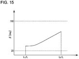
- the arrangement position of the vortex generator is determined such that the mounting angle ⁇ with reference to the leading edge increases toward the blade tip side.
- FIG. 15 is a graph showing a relationship between the radial directional position from the blade root 3 and the mounting angle according to an embodiment.
- an expression of relative or absolute arrangement such as “in a direction”, “along a direction”, “parallel”, “orthogonal”, “centered”, “concentric” and “coaxial” shall not be construed as indicating only the arrangement in a strict literal sense, but also includes a state where the arrangement is relatively displaced by a tolerance, or by an angle or a distance whereby it is possible to achieve the same function.
- an expression of an equal state such as “same” “equal” and “uniform” shall not be construed as indicating only the state in which the feature is strictly equal, but also includes a state in which there is a tolerance or a difference that can still achieve the same function.
- an expression of a shape such as a rectangular shape or a cylindrical shape shall not be construed as only the geometrically strict shape, but also includes a shape with unevenness or chamfered corners within the range in which the same effect can be achieved.
Landscapes
- Engineering & Computer Science (AREA)
- Life Sciences & Earth Sciences (AREA)
- Sustainable Development (AREA)
- Sustainable Energy (AREA)
- Chemical & Material Sciences (AREA)
- Combustion & Propulsion (AREA)
- Mechanical Engineering (AREA)
- General Engineering & Computer Science (AREA)
- Physics & Mathematics (AREA)
- Fluid Mechanics (AREA)
- Wind Motors (AREA)
Applications Claiming Priority (1)
| Application Number | Priority Date | Filing Date | Title |
|---|---|---|---|
| JP2017131771A JP6732697B2 (ja) | 2017-07-05 | 2017-07-05 | 風車翼へのボルテックスジェネレータの配置位置決定方法、風車翼アセンブリの製造方法及び風車翼アセンブリ |
Publications (2)
| Publication Number | Publication Date |
|---|---|
| EP3431750A1 true EP3431750A1 (fr) | 2019-01-23 |
| EP3431750B1 EP3431750B1 (fr) | 2020-04-22 |
Family
ID=62152475
Family Applications (1)
| Application Number | Title | Priority Date | Filing Date |
|---|---|---|---|
| EP18171891.7A Active EP3431750B1 (fr) | 2017-07-05 | 2018-05-11 | Procédé de détermination de la position d'agencement d'un générateur de vortex sur une pale de turbine éolienne, procédé de fabrication d'un ensemble de pales de turbine éolienne et ensemble de pales de turbine éolienne |
Country Status (3)
| Country | Link |
|---|---|
| US (1) | US11300096B2 (fr) |
| EP (1) | EP3431750B1 (fr) |
| JP (1) | JP6732697B2 (fr) |
Families Citing this family (4)
| Publication number | Priority date | Publication date | Assignee | Title |
|---|---|---|---|---|
| JP6783212B2 (ja) * | 2017-10-20 | 2020-11-11 | 三菱重工業株式会社 | 風車翼へのボルテックスジェネレータの配置位置決定方法、風車翼アセンブリの製造方法及び風車翼アセンブリ |
| DE102018117398A1 (de) * | 2018-07-18 | 2020-01-23 | Wobben Properties Gmbh | Rotorblatt für eine Windenergieanlage und Windenergieanlage |
| DE102018121190A1 (de) * | 2018-08-30 | 2020-03-05 | Wobben Properties Gmbh | Rotorblatt, Windenergieanlage und Verfahren zum Optimieren einer Windenergieanlage |
| CN113836839B (zh) * | 2021-09-30 | 2023-12-08 | 中国华能集团清洁能源技术研究院有限公司 | 一种基于流场可视化的涡流发生器弦向定位方法 |
Citations (11)
| Publication number | Priority date | Publication date | Assignee | Title |
|---|---|---|---|---|
| WO2006122547A1 (fr) | 2005-05-17 | 2006-11-23 | Vestas Wind Systems A/S | Pale d’aérogénérateur à inclinaison contrôlée, aérogénérateur et son utilisation |
| WO2007114698A2 (fr) | 2006-04-02 | 2007-10-11 | Gustave Paul Corten | Éolienne à pales éffilées |
| WO2007140771A1 (fr) | 2006-06-09 | 2007-12-13 | Vestas Wind Systems A/S | Pale d'éolienne et éolienne à régulation de pas |
| EP1944505A1 (fr) | 2007-01-12 | 2008-07-16 | Siemens Aktiengesellschaft | Aube de rotor d'éolienne avec générateurs de tourbillons |
| EP2201243A2 (fr) | 2007-08-29 | 2010-06-30 | Lm Glasfiber A/S | Pale de rotor pour éolienne dotée de moyens générateurs de barrière |
| EP2484895A1 (fr) | 2011-02-04 | 2012-08-08 | LM Wind Power A/S | Paire d'aubes de générateur de tourbillons doté d'une base en forme de trapèze |
| WO2013014082A2 (fr) | 2011-07-22 | 2013-01-31 | Lm Wind Power A/S | Pale de turbine éolienne comprenant des générateurs de tourbillons |
| US20140219810A1 (en) * | 2011-07-22 | 2014-08-07 | Lm Wp Patent Holding A/S | Vortex generator arrangement for an airfoil |
| EP2799710A1 (fr) | 2013-05-03 | 2014-11-05 | General Electric Company | Ensemble de pale de rotor comportant des générateurs de tourbillons pour éolienne |
| WO2015030573A1 (fr) | 2013-09-02 | 2015-03-05 | Corten Holding Bv | Générateur de vortex pour éolienne |
| JP6154050B1 (ja) * | 2016-08-08 | 2017-06-28 | 三菱重工業株式会社 | 風車翼、風車ロータ及び風力発電装置並びにボルテックスジェネレータの取付方法 |
Family Cites Families (1)
| Publication number | Priority date | Publication date | Assignee | Title |
|---|---|---|---|---|
| DE102013202666A1 (de) * | 2013-02-19 | 2014-08-21 | Senvion Se | Rotorblatt einer Windenergieanlage |
-
2017
- 2017-07-05 JP JP2017131771A patent/JP6732697B2/ja active Active
-
2018
- 2018-05-11 EP EP18171891.7A patent/EP3431750B1/fr active Active
- 2018-05-24 US US15/988,835 patent/US11300096B2/en active Active
Patent Citations (12)
| Publication number | Priority date | Publication date | Assignee | Title |
|---|---|---|---|---|
| WO2006122547A1 (fr) | 2005-05-17 | 2006-11-23 | Vestas Wind Systems A/S | Pale d’aérogénérateur à inclinaison contrôlée, aérogénérateur et son utilisation |
| WO2007114698A2 (fr) | 2006-04-02 | 2007-10-11 | Gustave Paul Corten | Éolienne à pales éffilées |
| WO2007140771A1 (fr) | 2006-06-09 | 2007-12-13 | Vestas Wind Systems A/S | Pale d'éolienne et éolienne à régulation de pas |
| EP2027390A1 (fr) | 2006-06-09 | 2009-02-25 | Vestas Wind Systems A/S | Pale d'éolienne et éolienne à régulation de pas |
| EP1944505A1 (fr) | 2007-01-12 | 2008-07-16 | Siemens Aktiengesellschaft | Aube de rotor d'éolienne avec générateurs de tourbillons |
| EP2201243A2 (fr) | 2007-08-29 | 2010-06-30 | Lm Glasfiber A/S | Pale de rotor pour éolienne dotée de moyens générateurs de barrière |
| EP2484895A1 (fr) | 2011-02-04 | 2012-08-08 | LM Wind Power A/S | Paire d'aubes de générateur de tourbillons doté d'une base en forme de trapèze |
| WO2013014082A2 (fr) | 2011-07-22 | 2013-01-31 | Lm Wind Power A/S | Pale de turbine éolienne comprenant des générateurs de tourbillons |
| US20140219810A1 (en) * | 2011-07-22 | 2014-08-07 | Lm Wp Patent Holding A/S | Vortex generator arrangement for an airfoil |
| EP2799710A1 (fr) | 2013-05-03 | 2014-11-05 | General Electric Company | Ensemble de pale de rotor comportant des générateurs de tourbillons pour éolienne |
| WO2015030573A1 (fr) | 2013-09-02 | 2015-03-05 | Corten Holding Bv | Générateur de vortex pour éolienne |
| JP6154050B1 (ja) * | 2016-08-08 | 2017-06-28 | 三菱重工業株式会社 | 風車翼、風車ロータ及び風力発電装置並びにボルテックスジェネレータの取付方法 |
Also Published As
| Publication number | Publication date |
|---|---|
| US11300096B2 (en) | 2022-04-12 |
| US20190010917A1 (en) | 2019-01-10 |
| EP3431750B1 (fr) | 2020-04-22 |
| JP2019015201A (ja) | 2019-01-31 |
| JP6732697B2 (ja) | 2020-07-29 |
Similar Documents
| Publication | Publication Date | Title |
|---|---|---|
| EP3282120B1 (fr) | Pale d'éolienne, rotor d'éolienne, appareil de génération d'énergie éolienne et procédé de montage d'un générateur de vortex | |
| EP3473850B1 (fr) | Procédé de détermination de la position d'agencement d'un générateur de vortex sur une pale de turbine éolienne, procédé de fabrication d'un ensemble de pales de turbine éolienne et ensemble de pales de turbine éolienne | |
| EP3431750B1 (fr) | Procédé de détermination de la position d'agencement d'un générateur de vortex sur une pale de turbine éolienne, procédé de fabrication d'un ensemble de pales de turbine éolienne et ensemble de pales de turbine éolienne | |
| US11149707B2 (en) | Wind turbine blade and method for determining arrangement of vortex generator on wind turbine blade | |
| US10697427B2 (en) | Vortex generator and wind turbine blade assembly | |
| EP3348824B1 (fr) | Générateur de tourbillon, son procédé d'installation, pale d'éolienne et appareil de production d'énergie éolienne | |
| US10060274B2 (en) | Twisted blade root | |
| EP2604856A1 (fr) | Pale de turbine éolienne, dispositif générateur d'énergie éolienne équipé de cette pale et procédé de calcul pour une pale de turbine éolienne | |
| KR20130107370A (ko) | 풍차 날개 및 이것을 구비한 풍력 발전 장치 | |
| JP2019078191A5 (fr) | ||
| EP2910772B2 (fr) | Pale d'éolienne, rotor d'éolienne et système de générateur d'éolienne | |
| US8911214B2 (en) | Wind turbine blade, wind turbine generator including wind turbine blade, and method for designing wind turbine blade | |
| US11867145B2 (en) | Rotor blade for a wind power installation, wind power installation, and method for designing a rotor blade | |
| JP7469126B2 (ja) | 風車翼アセンブリ及び風車 | |
| EP2940292B1 (fr) | Dispositif pour pale de rotor d'une éolienne | |
| EP3786444A1 (fr) | Appareil de pale d'éolienne et élément de fixation de pale d'éolienne | |
| EP3916217A1 (fr) | Aube d'éolienne et procédé pour décider de l'agencement de générateurs de vortex pour une aube d'éolienne |
Legal Events
| Date | Code | Title | Description |
|---|---|---|---|
| PUAI | Public reference made under article 153(3) epc to a published international application that has entered the european phase |
Free format text: ORIGINAL CODE: 0009012 |
|
| STAA | Information on the status of an ep patent application or granted ep patent |
Free format text: STATUS: THE APPLICATION HAS BEEN PUBLISHED |
|
| AK | Designated contracting states |
Kind code of ref document: A1 Designated state(s): AL AT BE BG CH CY CZ DE DK EE ES FI FR GB GR HR HU IE IS IT LI LT LU LV MC MK MT NL NO PL PT RO RS SE SI SK SM TR |
|
| AX | Request for extension of the european patent |
Extension state: BA ME |
|
| RIC1 | Information provided on ipc code assigned before grant |
Ipc: F03D 1/06 20060101AFI20190117BHEP |
|
| STAA | Information on the status of an ep patent application or granted ep patent |
Free format text: STATUS: REQUEST FOR EXAMINATION WAS MADE |
|
| STAA | Information on the status of an ep patent application or granted ep patent |
Free format text: STATUS: EXAMINATION IS IN PROGRESS |
|
| 17P | Request for examination filed |
Effective date: 20190716 |
|
| RBV | Designated contracting states (corrected) |
Designated state(s): AL AT BE BG CH CY CZ DE DK EE ES FI FR GB GR HR HU IE IS IT LI LT LU LV MC MK MT NL NO PL PT RO RS SE SI SK SM TR |
|
| 17Q | First examination report despatched |
Effective date: 20190816 |
|
| GRAP | Despatch of communication of intention to grant a patent |
Free format text: ORIGINAL CODE: EPIDOSNIGR1 |
|
| STAA | Information on the status of an ep patent application or granted ep patent |
Free format text: STATUS: GRANT OF PATENT IS INTENDED |
|
| INTG | Intention to grant announced |
Effective date: 20200122 |
|
| GRAS | Grant fee paid |
Free format text: ORIGINAL CODE: EPIDOSNIGR3 |
|
| GRAA | (expected) grant |
Free format text: ORIGINAL CODE: 0009210 |
|
| STAA | Information on the status of an ep patent application or granted ep patent |
Free format text: STATUS: THE PATENT HAS BEEN GRANTED |
|
| AK | Designated contracting states |
Kind code of ref document: B1 Designated state(s): AL AT BE BG CH CY CZ DE DK EE ES FI FR GB GR HR HU IE IS IT LI LT LU LV MC MK MT NL NO PL PT RO RS SE SI SK SM TR |
|
| REG | Reference to a national code |
Ref country code: CH Ref legal event code: EP |
|
| REG | Reference to a national code |
Ref country code: DE Ref legal event code: R096 Ref document number: 602018003905 Country of ref document: DE |
|
| REG | Reference to a national code |
Ref country code: IE Ref legal event code: FG4D |
|
| REG | Reference to a national code |
Ref country code: AT Ref legal event code: REF Ref document number: 1260423 Country of ref document: AT Kind code of ref document: T Effective date: 20200515 |
|
| REG | Reference to a national code |
Ref country code: LT Ref legal event code: MG4D |
|
| REG | Reference to a national code |
Ref country code: NL Ref legal event code: MP Effective date: 20200422 |
|
| PG25 | Lapsed in a contracting state [announced via postgrant information from national office to epo] |
Ref country code: GR Free format text: LAPSE BECAUSE OF FAILURE TO SUBMIT A TRANSLATION OF THE DESCRIPTION OR TO PAY THE FEE WITHIN THE PRESCRIBED TIME-LIMIT Effective date: 20200723 Ref country code: FI Free format text: LAPSE BECAUSE OF FAILURE TO SUBMIT A TRANSLATION OF THE DESCRIPTION OR TO PAY THE FEE WITHIN THE PRESCRIBED TIME-LIMIT Effective date: 20200422 Ref country code: LT Free format text: LAPSE BECAUSE OF FAILURE TO SUBMIT A TRANSLATION OF THE DESCRIPTION OR TO PAY THE FEE WITHIN THE PRESCRIBED TIME-LIMIT Effective date: 20200422 Ref country code: IS Free format text: LAPSE BECAUSE OF FAILURE TO SUBMIT A TRANSLATION OF THE DESCRIPTION OR TO PAY THE FEE WITHIN THE PRESCRIBED TIME-LIMIT Effective date: 20200822 Ref country code: SE Free format text: LAPSE BECAUSE OF FAILURE TO SUBMIT A TRANSLATION OF THE DESCRIPTION OR TO PAY THE FEE WITHIN THE PRESCRIBED TIME-LIMIT Effective date: 20200422 Ref country code: NO Free format text: LAPSE BECAUSE OF FAILURE TO SUBMIT A TRANSLATION OF THE DESCRIPTION OR TO PAY THE FEE WITHIN THE PRESCRIBED TIME-LIMIT Effective date: 20200722 Ref country code: NL Free format text: LAPSE BECAUSE OF FAILURE TO SUBMIT A TRANSLATION OF THE DESCRIPTION OR TO PAY THE FEE WITHIN THE PRESCRIBED TIME-LIMIT Effective date: 20200422 Ref country code: PT Free format text: LAPSE BECAUSE OF FAILURE TO SUBMIT A TRANSLATION OF THE DESCRIPTION OR TO PAY THE FEE WITHIN THE PRESCRIBED TIME-LIMIT Effective date: 20200824 |
|
| REG | Reference to a national code |
Ref country code: AT Ref legal event code: MK05 Ref document number: 1260423 Country of ref document: AT Kind code of ref document: T Effective date: 20200422 |
|
| PG25 | Lapsed in a contracting state [announced via postgrant information from national office to epo] |
Ref country code: HR Free format text: LAPSE BECAUSE OF FAILURE TO SUBMIT A TRANSLATION OF THE DESCRIPTION OR TO PAY THE FEE WITHIN THE PRESCRIBED TIME-LIMIT Effective date: 20200422 Ref country code: RS Free format text: LAPSE BECAUSE OF FAILURE TO SUBMIT A TRANSLATION OF THE DESCRIPTION OR TO PAY THE FEE WITHIN THE PRESCRIBED TIME-LIMIT Effective date: 20200422 Ref country code: BG Free format text: LAPSE BECAUSE OF FAILURE TO SUBMIT A TRANSLATION OF THE DESCRIPTION OR TO PAY THE FEE WITHIN THE PRESCRIBED TIME-LIMIT Effective date: 20200722 Ref country code: LV Free format text: LAPSE BECAUSE OF FAILURE TO SUBMIT A TRANSLATION OF THE DESCRIPTION OR TO PAY THE FEE WITHIN THE PRESCRIBED TIME-LIMIT Effective date: 20200422 |
|
| PG25 | Lapsed in a contracting state [announced via postgrant information from national office to epo] |
Ref country code: AL Free format text: LAPSE BECAUSE OF FAILURE TO SUBMIT A TRANSLATION OF THE DESCRIPTION OR TO PAY THE FEE WITHIN THE PRESCRIBED TIME-LIMIT Effective date: 20200422 |
|
| REG | Reference to a national code |
Ref country code: DE Ref legal event code: R097 Ref document number: 602018003905 Country of ref document: DE |
|
| PG25 | Lapsed in a contracting state [announced via postgrant information from national office to epo] |
Ref country code: MC Free format text: LAPSE BECAUSE OF FAILURE TO SUBMIT A TRANSLATION OF THE DESCRIPTION OR TO PAY THE FEE WITHIN THE PRESCRIBED TIME-LIMIT Effective date: 20200422 Ref country code: ES Free format text: LAPSE BECAUSE OF FAILURE TO SUBMIT A TRANSLATION OF THE DESCRIPTION OR TO PAY THE FEE WITHIN THE PRESCRIBED TIME-LIMIT Effective date: 20200422 Ref country code: DK Free format text: LAPSE BECAUSE OF FAILURE TO SUBMIT A TRANSLATION OF THE DESCRIPTION OR TO PAY THE FEE WITHIN THE PRESCRIBED TIME-LIMIT Effective date: 20200422 Ref country code: EE Free format text: LAPSE BECAUSE OF FAILURE TO SUBMIT A TRANSLATION OF THE DESCRIPTION OR TO PAY THE FEE WITHIN THE PRESCRIBED TIME-LIMIT Effective date: 20200422 Ref country code: SM Free format text: LAPSE BECAUSE OF FAILURE TO SUBMIT A TRANSLATION OF THE DESCRIPTION OR TO PAY THE FEE WITHIN THE PRESCRIBED TIME-LIMIT Effective date: 20200422 Ref country code: IT Free format text: LAPSE BECAUSE OF FAILURE TO SUBMIT A TRANSLATION OF THE DESCRIPTION OR TO PAY THE FEE WITHIN THE PRESCRIBED TIME-LIMIT Effective date: 20200422 Ref country code: AT Free format text: LAPSE BECAUSE OF FAILURE TO SUBMIT A TRANSLATION OF THE DESCRIPTION OR TO PAY THE FEE WITHIN THE PRESCRIBED TIME-LIMIT Effective date: 20200422 Ref country code: CZ Free format text: LAPSE BECAUSE OF FAILURE TO SUBMIT A TRANSLATION OF THE DESCRIPTION OR TO PAY THE FEE WITHIN THE PRESCRIBED TIME-LIMIT Effective date: 20200422 Ref country code: RO Free format text: LAPSE BECAUSE OF FAILURE TO SUBMIT A TRANSLATION OF THE DESCRIPTION OR TO PAY THE FEE WITHIN THE PRESCRIBED TIME-LIMIT Effective date: 20200422 |
|
| PG25 | Lapsed in a contracting state [announced via postgrant information from national office to epo] |
Ref country code: PL Free format text: LAPSE BECAUSE OF FAILURE TO SUBMIT A TRANSLATION OF THE DESCRIPTION OR TO PAY THE FEE WITHIN THE PRESCRIBED TIME-LIMIT Effective date: 20200422 Ref country code: SK Free format text: LAPSE BECAUSE OF FAILURE TO SUBMIT A TRANSLATION OF THE DESCRIPTION OR TO PAY THE FEE WITHIN THE PRESCRIBED TIME-LIMIT Effective date: 20200422 |
|
| PLBE | No opposition filed within time limit |
Free format text: ORIGINAL CODE: 0009261 |
|
| STAA | Information on the status of an ep patent application or granted ep patent |
Free format text: STATUS: NO OPPOSITION FILED WITHIN TIME LIMIT |
|
| REG | Reference to a national code |
Ref country code: BE Ref legal event code: MM Effective date: 20200531 |
|
| 26N | No opposition filed |
Effective date: 20210125 |
|
| PG25 | Lapsed in a contracting state [announced via postgrant information from national office to epo] |
Ref country code: LU Free format text: LAPSE BECAUSE OF NON-PAYMENT OF DUE FEES Effective date: 20200511 |
|
| PG25 | Lapsed in a contracting state [announced via postgrant information from national office to epo] |
Ref country code: IE Free format text: LAPSE BECAUSE OF NON-PAYMENT OF DUE FEES Effective date: 20200511 |
|
| PG25 | Lapsed in a contracting state [announced via postgrant information from national office to epo] |
Ref country code: BE Free format text: LAPSE BECAUSE OF NON-PAYMENT OF DUE FEES Effective date: 20200531 Ref country code: SI Free format text: LAPSE BECAUSE OF FAILURE TO SUBMIT A TRANSLATION OF THE DESCRIPTION OR TO PAY THE FEE WITHIN THE PRESCRIBED TIME-LIMIT Effective date: 20200422 |
|
| REG | Reference to a national code |
Ref country code: CH Ref legal event code: PL |
|
| PG25 | Lapsed in a contracting state [announced via postgrant information from national office to epo] |
Ref country code: LI Free format text: LAPSE BECAUSE OF NON-PAYMENT OF DUE FEES Effective date: 20210531 Ref country code: CH Free format text: LAPSE BECAUSE OF NON-PAYMENT OF DUE FEES Effective date: 20210531 |
|
| PG25 | Lapsed in a contracting state [announced via postgrant information from national office to epo] |
Ref country code: TR Free format text: LAPSE BECAUSE OF FAILURE TO SUBMIT A TRANSLATION OF THE DESCRIPTION OR TO PAY THE FEE WITHIN THE PRESCRIBED TIME-LIMIT Effective date: 20200422 Ref country code: MT Free format text: LAPSE BECAUSE OF FAILURE TO SUBMIT A TRANSLATION OF THE DESCRIPTION OR TO PAY THE FEE WITHIN THE PRESCRIBED TIME-LIMIT Effective date: 20200422 Ref country code: CY Free format text: LAPSE BECAUSE OF FAILURE TO SUBMIT A TRANSLATION OF THE DESCRIPTION OR TO PAY THE FEE WITHIN THE PRESCRIBED TIME-LIMIT Effective date: 20200422 |
|
| PG25 | Lapsed in a contracting state [announced via postgrant information from national office to epo] |
Ref country code: MK Free format text: LAPSE BECAUSE OF FAILURE TO SUBMIT A TRANSLATION OF THE DESCRIPTION OR TO PAY THE FEE WITHIN THE PRESCRIBED TIME-LIMIT Effective date: 20200422 |
|
| REG | Reference to a national code |
Ref country code: DE Ref legal event code: R082 Ref document number: 602018003905 Country of ref document: DE Representative=s name: CBDL PATENTANWAELTE GBR, DE |
|
| PGFP | Annual fee paid to national office [announced via postgrant information from national office to epo] |
Ref country code: GB Payment date: 20230330 Year of fee payment: 6 |
|
| PGFP | Annual fee paid to national office [announced via postgrant information from national office to epo] |
Ref country code: FR Payment date: 20230411 Year of fee payment: 6 Ref country code: DE Payment date: 20230331 Year of fee payment: 6 |