EP3431205A1 - Tube diameter expanding method and molding apparatus - Google Patents
Tube diameter expanding method and molding apparatus Download PDFInfo
- Publication number
- EP3431205A1 EP3431205A1 EP16894259.7A EP16894259A EP3431205A1 EP 3431205 A1 EP3431205 A1 EP 3431205A1 EP 16894259 A EP16894259 A EP 16894259A EP 3431205 A1 EP3431205 A1 EP 3431205A1
- Authority
- EP
- European Patent Office
- Prior art keywords
- tube
- roller
- forming region
- rod
- radial direction
- Prior art date
- Legal status (The legal status is an assumption and is not a legal conclusion. Google has not performed a legal analysis and makes no representation as to the accuracy of the status listed.)
- Granted
Links
- 238000000034 method Methods 0.000 title claims abstract description 25
- 238000000465 moulding Methods 0.000 title 1
- 238000010438 heat treatment Methods 0.000 claims abstract description 56
- 238000001816 cooling Methods 0.000 claims abstract description 34
- 230000002093 peripheral effect Effects 0.000 claims description 20
- 230000006698 induction Effects 0.000 claims description 11
- 239000003795 chemical substances by application Substances 0.000 description 9
- 230000006870 function Effects 0.000 description 7
- 239000000463 material Substances 0.000 description 6
- 230000007246 mechanism Effects 0.000 description 6
- 238000010586 diagram Methods 0.000 description 5
- 238000002844 melting Methods 0.000 description 4
- 230000008018 melting Effects 0.000 description 4
- 238000003825 pressing Methods 0.000 description 4
- 230000004048 modification Effects 0.000 description 3
- 238000012986 modification Methods 0.000 description 3
- 230000000630 rising effect Effects 0.000 description 3
- 230000000694 effects Effects 0.000 description 2
- 229910052751 metal Inorganic materials 0.000 description 2
- 239000002184 metal Substances 0.000 description 2
- 238000009987 spinning Methods 0.000 description 2
- 229910000838 Al alloy Inorganic materials 0.000 description 1
- 229910000831 Steel Inorganic materials 0.000 description 1
- 229910001069 Ti alloy Inorganic materials 0.000 description 1
- 230000009471 action Effects 0.000 description 1
- 230000002708 enhancing effect Effects 0.000 description 1
- 239000007789 gas Substances 0.000 description 1
- 239000011261 inert gas Substances 0.000 description 1
- 239000007788 liquid Substances 0.000 description 1
- 230000015654 memory Effects 0.000 description 1
- 230000005855 radiation Effects 0.000 description 1
- 230000009467 reduction Effects 0.000 description 1
- 239000010935 stainless steel Substances 0.000 description 1
- 229910001220 stainless steel Inorganic materials 0.000 description 1
- 239000010959 steel Substances 0.000 description 1
- XLYOFNOQVPJJNP-UHFFFAOYSA-N water Substances O XLYOFNOQVPJJNP-UHFFFAOYSA-N 0.000 description 1
Images


Classifications
-
- B—PERFORMING OPERATIONS; TRANSPORTING
- B21—MECHANICAL METAL-WORKING WITHOUT ESSENTIALLY REMOVING MATERIAL; PUNCHING METAL
- B21D—WORKING OR PROCESSING OF SHEET METAL OR METAL TUBES, RODS OR PROFILES WITHOUT ESSENTIALLY REMOVING MATERIAL; PUNCHING METAL
- B21D37/00—Tools as parts of machines covered by this subclass
- B21D37/16—Heating or cooling
-
- B—PERFORMING OPERATIONS; TRANSPORTING
- B21—MECHANICAL METAL-WORKING WITHOUT ESSENTIALLY REMOVING MATERIAL; PUNCHING METAL
- B21C—MANUFACTURE OF METAL SHEETS, WIRE, RODS, TUBES OR PROFILES, OTHERWISE THAN BY ROLLING; AUXILIARY OPERATIONS USED IN CONNECTION WITH METAL-WORKING WITHOUT ESSENTIALLY REMOVING MATERIAL
- B21C37/00—Manufacture of metal sheets, bars, wire, tubes or like semi-manufactured products, not otherwise provided for; Manufacture of tubes of special shape
- B21C37/06—Manufacture of metal sheets, bars, wire, tubes or like semi-manufactured products, not otherwise provided for; Manufacture of tubes of special shape of tubes or metal hoses; Combined procedures for making tubes, e.g. for making multi-wall tubes
- B21C37/15—Making tubes of special shape; Making tube fittings
- B21C37/16—Making tubes with varying diameter in longitudinal direction
- B21C37/18—Making tubes with varying diameter in longitudinal direction conical tubes
-
- B—PERFORMING OPERATIONS; TRANSPORTING
- B21—MECHANICAL METAL-WORKING WITHOUT ESSENTIALLY REMOVING MATERIAL; PUNCHING METAL
- B21D—WORKING OR PROCESSING OF SHEET METAL OR METAL TUBES, RODS OR PROFILES WITHOUT ESSENTIALLY REMOVING MATERIAL; PUNCHING METAL
- B21D22/00—Shaping without cutting, by stamping, spinning, or deep-drawing
- B21D22/14—Spinning
-
- B—PERFORMING OPERATIONS; TRANSPORTING
- B21—MECHANICAL METAL-WORKING WITHOUT ESSENTIALLY REMOVING MATERIAL; PUNCHING METAL
- B21D—WORKING OR PROCESSING OF SHEET METAL OR METAL TUBES, RODS OR PROFILES WITHOUT ESSENTIALLY REMOVING MATERIAL; PUNCHING METAL
- B21D41/00—Application of procedures in order to alter the diameter of tube ends
- B21D41/02—Enlarging
- B21D41/021—Enlarging by means of tube-flaring hand tools
- B21D41/023—Enlarging by means of tube-flaring hand tools comprising rolling elements
Definitions
- the present invention relates to a tube diameter expanding method and a forming apparatus for implementing the same.
- PTL 1 discloses a tube diameter expanding method using a pair of disk rollers.
- a tube having one end thereof fixed to a turntable is rotated about a center axis of the tube in a state where the tube is sandwiched between a first roller disposed in the tube and a second roller disposed outside the tube. Then, the first roller and the second roller are moved in a direction from one end toward the other end of the tube and outward in a radial direction of the tube. As a result, the first roller presses the tube, and a section extending from the pressed position to the other end is expanded in diameter.
- the second roller plays a role of enhancing formability of the diameter-expanded section.
- an object of the present invention is to suppress deformation of a non-forming region of a heated tube when a rod-like roller is pressed against a heated forming region of the tube.
- the present invention provides a tube diameter expanding method including: a step for rotating a tube having one end fixed to a turntable about a center axis of the tube; a step for inserting a rod-like roller extending in an axial direction of the tube into the tube from the other end of the tube, and bringing the rod-like roller into contact with a forming region extending from the other end to a predetermined position of the tube; a step for heating the forming region of the tube; a step for cooling at least a section located near the forming region and within a non-forming region extending from the predetermined position to the one end of the tube; and a step for moving the rod-like roller in a state of contacting the forming region of the tube, in a direction from the one end of the tube toward the other end of the tube and outward in a radial direction of the tube.
- the rod-like roller is pressed against the heated forming region of the tube. Therefore, it is possible to expand the forming region in diameter with a relatively small pushing force while suppressing occurrence of necking.
- the section located near the forming region and within the non-forming region of the tube is cooled, it is possible to suppress deformation of the non-forming region when the rod-like roller is pressed against the heated forming region.
- the forming region of the tube may be heated from outside of the tube. According to this configuration, it is possible to further suppress protrusion of an inner peripheral surface of the tube which may be caused by pressing of the rod-like roller as compared to a case where the forming region is heated from inside of the tube.
- the forming region of the tube may be heated by induction heating.
- induction heating In a case where a burner is used to heat the forming region of the tube, a temperature gradient between the forming region and the non-forming region becomes gentle. In contrast, in a case where the forming region is heated by induction heating, the temperature gradient between the forming region and the non-forming region becomes steep. Therefore, if the forming region is heated by induction heating, deformation of the non-forming region can be more effectively suppressed. In other words, it is possible to accurately form a tapered portion in the non-forming region indicating a track of the rod-like roller.
- the forming region of the tube may be heated by using a heater including a heating head that faces an inner peripheral surface or an outer peripheral surface of the tube.
- a heater including a heating head that faces an inner peripheral surface or an outer peripheral surface of the tube.
- the non-forming region of the tube may be cooled by using a cooler including a cooling head that supplies cooler agent to the outer peripheral surface of the tube.
- a cooler including a cooling head that supplies cooler agent to the outer peripheral surface of the tube.
- the rod-like roller in a state of contacting the forming region of the tube may be moved in the direction from the one end toward the other end of the tube and outward in the radial direction of the tube. According to this configuration, deflection of the tube during forming can be prevented.
- the tip of the rod-like roller may be flat. According to this configuration, it is possible to further suppress interference between the rod-like roller and the tapered portion in the non-forming region indicating the track of the rod-like roller as compared to a case where the tip of the rod-like roller is semi-spherical. Therefore, it is possible to accurately expand the forming region of the tube in diameter.
- the tube may have a thickness of 8 mm or more.
- the present invention provides a forming apparatus including: a turntable to which one end of a tube is fixed; a rod-like roller which extends in an axial direction of the tube, the rod-like roller being inserted into the tube from the other end of the tube and being brought into contact with a forming region extending from the other end of the tube to a predetermined position; a heater which heats the forming region of the tube; a cooler which cools at least a section located near the forming region and within a non-forming region extending from the predetermined position to the one end of the tube; and a roller moving device which moves the rod-like roller in the axial direction and a radial direction of the tube.
- the present invention it is possible to suppress deformation of the non-forming region of the heated tube when the rod-like roller is pressed against the heated forming region of the tube.
- Embodiment 1 of the present invention a tube diameter expanding method according to Embodiment 1 of the present invention will be described.
- the diameter expanding method according to the present embodiment is implemented by a forming apparatus 1A illustrated in Fig. 1 .
- the forming apparatus 1A partially expands a tube 2 in diameter by spinning forming.
- the material constituting the tube 2 is not particularly limited; however, the diameter expanding method according to the present embodiment is particularly useful for the tube 2 made of metal having high deformation resistance.
- the metal having high deformation resistance include a worked material which is difficult to plastically deform such as stainless steel or a titanium alloy. Even if the tube 2 is not made of the worked material which is difficult to plastically deform but is made of soft steel or an aluminum alloy having a thickness of 8 mm or more, deformation resistance becomes high.
- the forming apparatus 1A includes a base 11 and a turntable 12 rotatably supported by the base 11.
- the turntable 12 is rotated by a motor, not illustrated.
- an axial direction of the turntable 12 is a vertical direction; however, the axial direction of the turntable 12 may be another direction such as a horizontal direction.
- a lower end (one end) of the tube 2 is fixed to the turntable 12 such that a center axis 20 of the tube 2 and a rotation center of the turntable 12 are aligned.
- the tube 2 is rotated about the center axis 20.
- the lower end of the tube 2 is fixed to the turntable 12 by a chuck 13 provided on the turntable 12.
- the method of fixing the lower end of the tube 2 to the turntable 12 is not limited to this.
- a tubular body fitted with the tube 2 may be provided on the turntable 12, and the lower end of the tube 2 may be fixed to the tubular body with a bolt.
- the forming apparatus 1A includes a rod-like roller 3 that presses the tube 2 from inside, a heater 4 that heats the tube 2 from outside, and a cooler 5 that cools the tube 2 from outside.
- the rod-like roller 3 extends in the axial direction of the tube 2 and has a cylindrical shape.
- the rod-like roller 3 is inserted into the tube 2 from an upper end (the other end) of the tube 2 and is brought into contact with a forming region 21 extending from the upper end to a predetermined position of the tube 2.
- a tip of the rod-like roller 3 is flat and parallel to a plane orthogonal to the axial direction of the tube 2. Therefore, a peripheral surface of the rod-like roller 3 is connected to a tip surface of the rod-like roller 3 via a curved portion of the rod-like roller 3, the curved portion having a small curvature radius.
- the axial direction of the rod-like roller 3 is not necessarily required to be perfectly parallel to the axial direction of the tube 2 but may be substantially parallel (for example, an angular difference between the axial directions is within ⁇ 10 degrees).
- the peripheral surface of the rod-like roller 3 may have a tubular shape parallel to the axial direction of the tube 2, or may be a tapered shape tapering upward or downward. Further, the peripheral surface of the rod-like roller 3 is not necessarily smooth and may have small unevenness.
- the rod-like roller 3 is provided with a shaft 31 that projects upward from an upper-end surface of the rod-like roller 3.
- the shaft 31 is rotatably supported by an arm 15.
- the rod-like roller 3 rotates following rotation of the tube 2 when the rod-like roller 3 contacts the forming region 21 of the tube 2.
- the arm 15 is connected to a first moving device 14 attached to a post 14a rising from the base 11.
- the first moving device 14 functions as a roller moving device that moves the rod-like roller 3 in the axial direction and a radial direction of the tube 2 via the arm 15.
- the first moving device 14 includes a pair of linear actuators whose axial directions are orthogonal to each other.
- Each linear actuator may be an electric/hydraulic/pneumatic cylinder, a ball screw mechanism, or a rack-and-pinion mechanism.
- the first moving device 14 may be a robot arm.
- the heater 4 heats the forming region 21 of the tube 2.
- the heater 4 heats the forming region 21 of the tube 2 by induction heating.
- the heater 4 includes a heating head 41 facing an outer peripheral surface of the tube 2, a plurality of coils 42 embedded in the heating head 41, and an AC power supply circuit 43 applying an AC voltage to the coils 42.
- a frequency of the AC voltage is a high frequency in a range from 5 k to 400 kHz.
- induction heating is desirably high-frequency induction heating.
- an angle between the heating head 41 and the rod-like roller 3 in a circumferential direction of the tube 2 is 180 degrees.
- the angle between the heating head 41 and the rod-like roller 3 in the circumferential direction of the tube 2 may be another angle such as 90 degrees.
- each coil 42 has an oval shape long in the circumferential direction of the tube 2.
- each of the coils 42 may have an oval shape long in the axial direction of the tube 2.
- only one coil 42 may be provided so as to form a polygon (for example, a triangle). Note that a plurality of heating heads 41 may be provided side by side in the circumferential direction of the tube 2.
- the cooler 5 cools at least a section (i.e., an upper portion) located near the forming region 21 and within a non-forming region 22 (i.e., the region other than the forming region 21 of the tube 2) extending from the predetermined position described above to the lower end of the tube 2.
- the cooler 5 cools the non-forming region 22 of the tube 2 by heat transfer to cooler agent.
- the cooler 5 includes a cooling head 51 that supplies cooler agent to the outer peripheral surface of the tube 2, and a delivery device 52 which delivers cooler agent to the cooling head 51 and whose revolution speed can be changed.
- the delivery device 52 may be a compressor or a fan.
- the delivery device 52 may be a pump.
- a heating temperature of the forming region 21 by the heater 4 is desirably not lower than one third of a melting point of the material constituting the tube 2, and more desirably not lower than one half of the melting point. It is desirable that a cooling temperature of the upper portion of the non-forming region 22 by the cooler 5 is set so that the upper portion of the non-forming region 22 is not deformed when the rod-like roller is pressed against the forming region 21.
- the heater 4 heats entirety of the forming region 21 to approximately an identical temperature.
- the cooler 5 desirably cools at least the upper portion of the non-forming region 22 such that the temperature is lowered to a temperature not higher than one quarter of the melting point of the material constituting the tube 2 in a minimal range extending from the upper end of the non-forming region 22 to a position slightly away from the upper end in the non-forming region 22.
- the minimal range is substantially equal to the height of the curved portion of the rod-like roller 3.
- the heating head 41 of the heater 4 and the cooling head 51 of the cooler 5 are attached to a holding plate 18.
- the holding plate 18 is connected to a second moving device 17 attached to a post 17a rising from the base 11.
- the second moving device 17 functions as a heating-head moving device that moves the heating head 41 in the axial direction and the radial direction of the tube 2 via the holding plate 18 and also functions as a cooling-head moving device that moves the cooling head 51 in the axial direction and the radial direction of the tube 2 via the holding plate 18.
- the second moving device 17 includes a pair of linear actuators whose axial directions are orthogonal to each other.
- Each linear actuator may be an electric/hydraulic/pneumatic cylinder, a ball screw mechanism, or a rack-and-pinion mechanism.
- the second moving device 17 may be a robot arm.
- the heating head 41 may be attached to the arm 15, and the first moving device 14 may function as the heating-head moving device.
- the cooling head 51 may be attached to the arm 15, and the first moving device 14 may function as the cooling-head moving device.
- a moving device exclusive for the heating head 41 and a moving device exclusive for the cooling head 51 may be separately provided.
- control device 6 may be a sequencer (registered trademark), or may be a computer including a CPU and memories such as a ROM and a RAM.
- the control device 6 is connected to a first temperature sensor 61 and a second temperature sensor 62.
- the first temperature sensor 61 detects the temperature of the forming region 21 of the tube 2.
- the second temperature sensor 62 detects the temperature of the upper portion of the non-forming region 22 of the tube 2.
- each of the first temperature sensor 61 and the second temperature sensor is a radiation thermometer that detects temperature according to infrared light or visible light.
- the first temperature sensor 61 and the second temperature sensor 62 are attached to a bracket 16 suspended from the arm 15.
- the first temperature sensor 61 and the second temperature sensor 62 move together with the rod-like roller 3.
- the first temperature sensor 61 and the second temperature sensor 62 may be attached to the holding plate 18.
- the first temperature sensor 61 and the second temperature sensor 62 may be moved by a moving device other than the first moving device 14 and the second moving device 17, or may be fixed in a fixed position.
- the control device 6 controls output from the heater 4 and the cooler 5. Specifically, the control device 6 controls the AC power supply circuit 43 of the heater 4 according to the temperature detected by the first temperature sensor 61, and controls the delivery device 52 of the cooler 5 according to the temperature detected by the second temperature sensor 62. However, in lieu of the delivery device 52 whose revolution speed can be changed, a delivery device whose revolution speed is constant and a flow control valve provided in a flow path from the delivery device to the cooling head may be used, and the flow control valve may be controlled by the control device 6.
- the first moving device 14 inserts the rod-like roller 3 into the tube 2 from the upper end of the tube 2 and brings the rod-like roller 3 into contact with the forming region 21 of the tube 2 (see Fig. 2 ). Then, the turntable 12 rotates the tube 2 about the center axis 20. However, rotation of the tube 2 may be started before the rod-like roller 3 is inserted into the tube 2.
- the heater 4 heats the forming region 21, and the cooler 5 cools at least the upper portion of the non-forming region 22.
- the first moving device 14 moves the rod-like roller 3 in a state of contacting the forming region 21 of the tube 2, in a direction from the lower end toward the upper end of the tube 2 (i.e., upward) and outward in the radial direction of the tube 2.
- the second moving device 17 moves the heating head 41 and the cooling head 51 in the axial direction and the radial direction of the tube 2 in synchronization with movement of the rod-like roller 3.
- synchronization means that, in each of the axial direction and the radial direction of the tube 2, a movement amount of the heating head 41 and the cooling head 51 is identical to a movement amount of the rod-like roller 3.
- movement of the rod-like roller 3 in the axial direction of the tube 2 and movement of the rod-like roller 3 in the radial direction of the tube 2 are separately and intermittently performed, as will be described later.
- the heating head 41 and the cooling head 51 are moved only in the axial direction of the tube 2 by the amount identical to the movement amount of the rod-like roller 3.
- the heating head 41 and the cooling head 51 are moved only in the radial direction of the tube 2 by the amount identical to the movement amount of the rod-like roller 3.
- the control device 6 controls the AC power supply circuit 43 of the heater 4 so that the temperature detected by the first temperature sensor 61 becomes a desired temperature and controls the delivery device 52 of the cooler 5 so that the temperature detected by the second temperature sensor 62 becomes a desired temperature.
- the forming region 21 gradually narrows and the non-forming region 22 gradually widens (see Fig. 3 ) accordingly.
- the section which is the lower end of the forming region 21 becomes a tapered portion expanded in diameter (i.e., the tapered portion indicates a track of the rod-like roller 3), and the tapered portion becomes part of the non-forming region 22.
- Each of movement of the rod-like roller 3 in the axial direction of the tube 2 and movement of the rod-like roller 3 in the radial direction of the tube 2 may be performed continuously or the movements may be performed separately and intermittently.
- the movement amount of the rod-like roller 3 in the axial direction of the tube 2 may be far greater (the angle of the tapered portion in the non-forming region 22 is small), or may be far smaller (the angle of the tapered portion in the non-forming region 22 is large) than the movement amount of the rod-like roller 3 in the radial direction of the tube 2.
- Movement of the rod-like roller 3 upward and outward in the radial direction of the tube 2 is terminated when the forming region 21 is expanded in diameter by a desired amount as illustrated in Fig. 3 . Therefore, it is possible to expand the tube 2 in diameter such that the tapered portion exists between a small-diameter tubular portion and a large-diameter tubular portion, in other words, the tube 2 has one stepped portion. Then, after once the rod-like roller 3 is removed from the tube 2 and moved slightly upward, the above-described operation is repeated. Thus, the tube 2 can be expanded in diameter such that the tube 2 has a plurality of stepped portions. However, the rod-like roller 3 may be moved upward to the upper end of the tube 2 in order to expand the tube 2 in diameter such that the tube 2 only has the small-diameter tubular portion and the tapered portion.
- the rod-like roller 3 is pressed against the heated forming region 21 of the tube 2. Therefore, it is possible to expand the forming region 21 in diameter with a relatively small pushing force while suppressing occurrence of necking.
- the rod-like roller 3 is pressed against the heated forming region 21.
- the heating head 41 is moved in the radial direction of the tube 2 in synchronization with movement of the rod-like roller 3 in the radial direction of the tube 2, the distance between the forming region 21 of the tube 2 and the heating head 41 can be kept approximately constant. Therefore, it is possible to expand the forming region 21 in diameter while stably heating the forming region 21.
- the heating head 41 is also moved in the axial direction of the tube 2 in synchronization with movement of the rod-like roller 3 in the axial direction of the tube 2. Therefore, it is possible to keep positional relationship between the tip of the rod-like roller 3 and the heating head 41 unchanged even if the forming region 21 gradually narrows as the rod-like roller 3 moves in the axial direction of the tube 2.
- the cooling head 51 is moved in synchronization with movement of the rod-like roller 3. Therefore, it is possible to keep positional relationship between the tip of the rod-like roller 3 and the cooling head 51 unchanged even if the forming region 21 gradually narrows as the rod-like roller 3 moves in the axial direction of the tube 2. Therefore, at least the upper portion of the non-forming region 22 can be continuously cooled.
- a forming apparatus 1B illustrated in Fig. 6 implements the tube diameter expanding method.
- an angle between a heating head 41 and a rod-like roller 3 in a circumferential direction of a tube 2 is 90 degrees.
- the rod-like roller 3 is moved in an up-down direction and a direction orthogonal to the paper surface of Fig. 6 by a first moving device 14 (not illustrated in Fig. 6 ).
- the forming apparatus 1B includes an auxiliary roller 7.
- the other configuration of the forming apparatus 1B is identical to that of the forming apparatus 1A of Embodiment 1.
- the auxiliary roller 7 extends in an axial direction of the tube 2 and has a cylindrical shape with a semi-spherical tip.
- an angle between the rod-like roller 3 and the auxiliary roller 7 in the circumferential direction of the tube 2 is 90 degrees.
- the angle between the rod-like roller 3 and the auxiliary roller 7 in the circumferential direction of the tube 2 may be another angle such as 180 degrees.
- the auxiliary roller 7 comes into contact with at least an upper portion (section including an upper end of the tube 2) of a forming region 21 from outside the tube 2.
- a length of the auxiliary roller 7 is shorter than a length of the rod-like roller 3 and comes into contact with only the upper portion of the forming region 21.
- the length of the auxiliary roller 7 may be equal to or longer than that of the rod-like roller 3, and the auxiliary roller 7 may be brought into contact with entirety of the forming region 21.
- the auxiliary roller 7 is provided with a shaft 71 that projects upward from an upper-end surface of the auxiliary roller 7.
- the shaft 71 is rotatably supported by an arm 81.
- the auxiliary roller 7 rotates following rotation of the tube 2 when the auxiliary roller 7 contacts the upper portion of the forming region 21 of the tube 2.
- the arm 81 is connected to a linear actuator 82 attached to a post 83 rising from a base 11.
- the linear actuator 82 moves the auxiliary roller 7 in a radial direction of the tube 2 via the arm 81.
- the linear actuator 82 may be an electric/hydraulic/pneumatic cylinder, a ball screw mechanism, or a rack-and-pinion mechanism.
- the linear actuator 82 is controlled by a control device 6 so that the auxiliary roller 7 is always pressed against the tube 2 with a constant pressing force.
- the auxiliary roller 7 supports at least the upper end of the tube 2 from outside in the radial direction.
- the rod-like roller 3 is pressed against the forming region 21.
- a thickness of the forming region 21 becomes thinner as the diameter expands. Therefore, a moving speed of the auxiliary roller 7 in the radial direction of the tube 2 is slower than a moving speed of the rod-like roller 3 in the radial direction of the tube 2.
- a heater 4 may be disposed such that a heating head 41 faces an inner peripheral surface of a tube 2, and a forming region 21 may be heated from inside of the tube 2.
- a forming region 21 may be heated from outside of the tube 2, it is possible to further suppress protrusion of the inner peripheral surface of the tube 2 which may be caused by pressing of a rod-like roller 3 as compared to a case where the forming region 21 is heated from inside of the tube 2.
- a cooler 5 may also be disposed such that a cooling head 51 supplies cooler agent to the inner peripheral surface of the tube 2, and may cool at least an upper portion of a non-forming region 22 from inside of the tube 2.
- the heater 4 does not necessarily heat the forming region 21 of the tube 2 by induction heating.
- a burner emitting a flame from a nozzle may be used as the heater 4.
- a temperature gradient between the forming region 21 and the non-forming region 22 becomes gentle.
- the temperature gradient between the forming region 21 and the non-forming region 22 becomes steep. Therefore, if the forming region 21 is heated by induction heating, deformation of the non-forming region 22 can be more effectively suppressed. In other words, it is possible to accurately form a tapered portion in the non-forming region 22 indicating a track of the rod-like roller 3.
- a second moving device 17 may not have the function of moving the heating head 41 and the cooling head 51 in the axial direction of the tube 2, and may only have the function of moving the heating head 41 and the cooling head 51 in the radial direction of the tube 2.
- a first moving device 14 moves the rod-like roller 3 in a state of contacting the forming region 21 of the tube 2, upward and outward in the radial direction of the tube 2
- the second moving device 17 may move the heating head 41 and the cooling head 51 in the radial direction of the tube 2 in synchronization with only movement of the rod-like roller 3 in the radial direction of the tube 2.
- either one or both of the heating head 41 and the cooling head 51 may be fixed in a fixed position.
- the cooling head 51 may be fixed at a fixed position and a supply amount of cooler agent to be supplied to the inner peripheral surface or an outer peripheral surface of the tube 2 may be controlled according to a second temperature sensor 62.
- the cooler 5 does not necessarily have to cool at least the upper portion of the non-forming region 22 of the tube 2 by heat transfer to cooler agent.
- the cooler 5 may be configured to cool at least the upper portion of the non-forming region 22 by contacting a heat radiator that deforms according to forming of the tube 2.
- a tip of the rod-like roller 3 may be semi-spherical. However, if the tip of the rod-like roller 3 is flat, it is possible to further suppress interference between the rod-like roller 3 and a tapered portion indicating the track of the rod-like roller 3 in the non-forming region 22 as compared to a case where the tip of the rod-like roller 3 is semi-spherical. Therefore, it is possible to accurately expand the forming region 21 of the tube 2 in diameter.
- heating of the forming region 21 of the tube 2, cooling of at least the upper portion of the non-forming region 22 of the tube 2, and pressing of the rod-like roller 3 against the forming region 21 are not necessarily performed simultaneously.
- the forming region 21 of the tube 2 may be heated, and then heating of the forming region 21 of the tube 2 may be stopped to cool the non-forming region 22. Thereafter, cooling of the non-forming region 22 may be stopped and the rod-like roller 3 may be pressed against the forming region 21.
Abstract
Description
- The present invention relates to a tube diameter expanding method and a forming apparatus for implementing the same.
- Conventionally, a method of partially expanding a tube in diameter by spinning forming is known. For example,
PTL 1 discloses a tube diameter expanding method using a pair of disk rollers. - Specifically, in the diameter expanding method disclosed in
PTL 1, a tube having one end thereof fixed to a turntable is rotated about a center axis of the tube in a state where the tube is sandwiched between a first roller disposed in the tube and a second roller disposed outside the tube. Then, the first roller and the second roller are moved in a direction from one end toward the other end of the tube and outward in a radial direction of the tube. As a result, the first roller presses the tube, and a section extending from the pressed position to the other end is expanded in diameter. The second roller plays a role of enhancing formability of the diameter-expanded section. - PTL 1:
JP 2000-246353 A - Incidentally, in a case where a tube is expanded in diameter by moving a disk roller disposed inside the tube in the radial direction and the axial direction of the tube, a section of the tube which is located at the other-end side of the disk roller tries to maintain the original diameter as illustrated in
Fig. 7 . Therefore, thickness reduction (so-called necking) occurs due to tension at a section of the tube which is located at the one-end side of the disk roller. In order to suppress occurrence necking as described above, it is desirable to use a rod-like roller extending in the axial direction of the tube in lieu of the disk roller. - However, in the case of using a rod-like roller, it is necessary to press a wide range of a forming region which is a region of the tube whose diameter is to be expanded. Therefore, it is necessary to push the rod-like roller outward in the radial direction with great force. In contrast, if the forming region of the tube is heated, pushing force of the rod-like roller can be reduced.
- However, in a case where the forming region of the tube is heated, a large amount of heat is given to the forming region, and the heat amount is also transmitted to a non-forming region of the tube which is located at the one-end side of the forming region. Therefore, when the rod-like roller is pressed against the forming region, the non-forming region also deforms.
- In view of the above, an object of the present invention is to suppress deformation of a non-forming region of a heated tube when a rod-like roller is pressed against a heated forming region of the tube.
- In order to solve the above-described problem, the present invention provides a tube diameter expanding method including: a step for rotating a tube having one end fixed to a turntable about a center axis of the tube; a step for inserting a rod-like roller extending in an axial direction of the tube into the tube from the other end of the tube, and bringing the rod-like roller into contact with a forming region extending from the other end to a predetermined position of the tube; a step for heating the forming region of the tube; a step for cooling at least a section located near the forming region and within a non-forming region extending from the predetermined position to the one end of the tube; and a step for moving the rod-like roller in a state of contacting the forming region of the tube, in a direction from the one end of the tube toward the other end of the tube and outward in a radial direction of the tube.
- According to the above configuration, the rod-like roller is pressed against the heated forming region of the tube. Therefore, it is possible to expand the forming region in diameter with a relatively small pushing force while suppressing occurrence of necking. In addition, since at least the section located near the forming region and within the non-forming region of the tube is cooled, it is possible to suppress deformation of the non-forming region when the rod-like roller is pressed against the heated forming region.
- The forming region of the tube may be heated from outside of the tube. According to this configuration, it is possible to further suppress protrusion of an inner peripheral surface of the tube which may be caused by pressing of the rod-like roller as compared to a case where the forming region is heated from inside of the tube.
- The forming region of the tube may be heated by induction heating. In a case where a burner is used to heat the forming region of the tube, a temperature gradient between the forming region and the non-forming region becomes gentle. In contrast, in a case where the forming region is heated by induction heating, the temperature gradient between the forming region and the non-forming region becomes steep. Therefore, if the forming region is heated by induction heating, deformation of the non-forming region can be more effectively suppressed. In other words, it is possible to accurately form a tapered portion in the non-forming region indicating a track of the rod-like roller.
- The forming region of the tube may be heated by using a heater including a heating head that faces an inner peripheral surface or an outer peripheral surface of the tube. When the rod-like roller in a state of contacting the forming region of the tube is moved in the direction from the one end toward the other end of the tube and outward in the radial direction of the tube, the heating head may be moved in the radial direction of the tube in synchronization with movement of the rod-like roller. According to this configuration, it is possible to keep a distance between the forming region of the tube and the heating head substantially constant, and it is possible to expand the forming region in diameter while stably heating the forming region.
- The non-forming region of the tube may be cooled by using a cooler including a cooling head that supplies cooler agent to the outer peripheral surface of the tube. When the rod-like roller in a state of contacting the forming region of the tube is moved in the direction from the one end toward the other end of the tube and outward in the radial direction of the tube, the cooling head may be moved in the axial direction and the radial direction of the tube in synchronization with movement of the rod-like roller. According to this configuration, a positional relationship between a tip of the rod-like roller and the cooling head is unchanged even if the forming region gradually narrows as the rod-like roller moves in the axial direction of the tube. Therefore, it is possible to continuously cool at least the section located near the forming region and within the non-forming region.
- In a state where an auxiliary roller supports at least the other end of the tube from outside in the radial direction, the rod-like roller in a state of contacting the forming region of the tube may be moved in the direction from the one end toward the other end of the tube and outward in the radial direction of the tube. According to this configuration, deflection of the tube during forming can be prevented.
- The tip of the rod-like roller may be flat. According to this configuration, it is possible to further suppress interference between the rod-like roller and the tapered portion in the non-forming region indicating the track of the rod-like roller as compared to a case where the tip of the rod-like roller is semi-spherical. Therefore, it is possible to accurately expand the forming region of the tube in diameter.
- For example, the tube may have a thickness of 8 mm or more.
- In addition, the present invention provides a forming apparatus including: a turntable to which one end of a tube is fixed; a rod-like roller which extends in an axial direction of the tube, the rod-like roller being inserted into the tube from the other end of the tube and being brought into contact with a forming region extending from the other end of the tube to a predetermined position; a heater which heats the forming region of the tube; a cooler which cools at least a section located near the forming region and within a non-forming region extending from the predetermined position to the one end of the tube; and a roller moving device which moves the rod-like roller in the axial direction and a radial direction of the tube. By using this forming apparatus, it is possible to implement the tube diameter expanding method described above.
- According to the present invention, it is possible to suppress deformation of the non-forming region of the heated tube when the rod-like roller is pressed against the heated forming region of the tube.
-
-
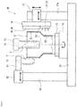
Fig. 1 is a schematic configuration diagram of a forming apparatus that implements a tube diameter expanding method according toEmbodiment 1 of the present invention. -
Fig. 2 is a diagram illustrating a positional relationship between a tube and a rod-like roller before forming is started. -
Fig. 3 is a diagram illustrating a positional relationship between the tube and the rod-like roller during forming. -
Fig. 4 is a cross-sectional view taken along line IV-IV inFig. 2 . -
Fig. 5A is a front view of a heating head used inEmbodiment 1,Fig. 5B is a front view of a heating head of a modification, andFig. 5C is a front view of a heating head of another modification. -
Fig. 6 is a schematic configuration diagram of a forming apparatus that implements a tube diameter expanding method according toEmbodiment 2 of the present invention. -
Fig. 7 is a diagram for describing necking occurring when a disk roller is used. - First, a tube diameter expanding method according to
Embodiment 1 of the present invention will be described. The diameter expanding method according to the present embodiment is implemented by a formingapparatus 1A illustrated inFig. 1 . - The forming
apparatus 1A partially expands atube 2 in diameter by spinning forming. The material constituting thetube 2 is not particularly limited; however, the diameter expanding method according to the present embodiment is particularly useful for thetube 2 made of metal having high deformation resistance. Examples of the metal having high deformation resistance include a worked material which is difficult to plastically deform such as stainless steel or a titanium alloy. Even if thetube 2 is not made of the worked material which is difficult to plastically deform but is made of soft steel or an aluminum alloy having a thickness of 8 mm or more, deformation resistance becomes high. - Specifically, the forming
apparatus 1A includes abase 11 and aturntable 12 rotatably supported by thebase 11. Theturntable 12 is rotated by a motor, not illustrated. In the present embodiment, an axial direction of theturntable 12 is a vertical direction; however, the axial direction of theturntable 12 may be another direction such as a horizontal direction. - A lower end (one end) of the
tube 2 is fixed to theturntable 12 such that acenter axis 20 of thetube 2 and a rotation center of theturntable 12 are aligned. To be specific, thetube 2 is rotated about thecenter axis 20. In the present embodiment, the lower end of thetube 2 is fixed to theturntable 12 by achuck 13 provided on theturntable 12. However, the method of fixing the lower end of thetube 2 to theturntable 12 is not limited to this. For example, in lieu of thechuck 13, a tubular body fitted with thetube 2 may be provided on theturntable 12, and the lower end of thetube 2 may be fixed to the tubular body with a bolt. - Further, the forming
apparatus 1A includes a rod-like roller 3 that presses thetube 2 from inside, aheater 4 that heats thetube 2 from outside, and acooler 5 that cools thetube 2 from outside. - The rod-
like roller 3 extends in the axial direction of thetube 2 and has a cylindrical shape. The rod-like roller 3 is inserted into thetube 2 from an upper end (the other end) of thetube 2 and is brought into contact with a formingregion 21 extending from the upper end to a predetermined position of thetube 2. In the present embodiment, a tip of the rod-like roller 3 is flat and parallel to a plane orthogonal to the axial direction of thetube 2. Therefore, a peripheral surface of the rod-like roller 3 is connected to a tip surface of the rod-like roller 3 via a curved portion of the rod-like roller 3, the curved portion having a small curvature radius. - The axial direction of the rod-
like roller 3 is not necessarily required to be perfectly parallel to the axial direction of thetube 2 but may be substantially parallel (for example, an angular difference between the axial directions is within ± 10 degrees). In addition, the peripheral surface of the rod-like roller 3 may have a tubular shape parallel to the axial direction of thetube 2, or may be a tapered shape tapering upward or downward. Further, the peripheral surface of the rod-like roller 3 is not necessarily smooth and may have small unevenness. - The rod-
like roller 3 is provided with ashaft 31 that projects upward from an upper-end surface of the rod-like roller 3. Theshaft 31 is rotatably supported by anarm 15. To be specific, the rod-like roller 3 rotates following rotation of thetube 2 when the rod-like roller 3 contacts the formingregion 21 of thetube 2. - The
arm 15 is connected to a first movingdevice 14 attached to apost 14a rising from thebase 11. The first movingdevice 14 functions as a roller moving device that moves the rod-like roller 3 in the axial direction and a radial direction of thetube 2 via thearm 15. In the present embodiment, the first movingdevice 14 includes a pair of linear actuators whose axial directions are orthogonal to each other. Each linear actuator may be an electric/hydraulic/pneumatic cylinder, a ball screw mechanism, or a rack-and-pinion mechanism. However, the first movingdevice 14 may be a robot arm. - The
heater 4 heats the formingregion 21 of thetube 2. In the present embodiment, theheater 4 heats the formingregion 21 of thetube 2 by induction heating. Specifically, as illustrated inFig. 2 , theheater 4 includes aheating head 41 facing an outer peripheral surface of thetube 2, a plurality ofcoils 42 embedded in theheating head 41, and an ACpower supply circuit 43 applying an AC voltage to thecoils 42. It is desirable that a frequency of the AC voltage is a high frequency in a range from 5 k to 400 kHz. To be specific, induction heating is desirably high-frequency induction heating. - In the present embodiment, as illustrated in
Fig. 4 , an angle between theheating head 41 and the rod-like roller 3 in a circumferential direction of thetube 2 is 180 degrees. However, the angle between theheating head 41 and the rod-like roller 3 in the circumferential direction of thetube 2 may be another angle such as 90 degrees. In addition, in the present embodiment, as illustrated inFigs. 4 and 5A , eachcoil 42 has an oval shape long in the circumferential direction of thetube 2. However, as illustrated inFig. 5B , each of thecoils 42 may have an oval shape long in the axial direction of thetube 2. Alternatively, as illustrated inFig. 5C , only onecoil 42 may be provided so as to form a polygon (for example, a triangle). Note that a plurality of heating heads 41 may be provided side by side in the circumferential direction of thetube 2. - Returning to
Fig. 2 , thecooler 5 cools at least a section (i.e., an upper portion) located near the formingregion 21 and within a non-forming region 22 (i.e., the region other than the formingregion 21 of the tube 2) extending from the predetermined position described above to the lower end of thetube 2. In the present embodiment, thecooler 5 cools thenon-forming region 22 of thetube 2 by heat transfer to cooler agent. Specifically, thecooler 5 includes a coolinghead 51 that supplies cooler agent to the outer peripheral surface of thetube 2, and adelivery device 52 which delivers cooler agent to the coolinghead 51 and whose revolution speed can be changed. For example, in a case where the cooler agent is a gas (for example, air or inert gas), thedelivery device 52 may be a compressor or a fan. Alternatively, in a case where the cooler agent is liquid (for example, water or oil), thedelivery device 52 may be a pump. - A heating temperature of the forming
region 21 by theheater 4 is desirably not lower than one third of a melting point of the material constituting thetube 2, and more desirably not lower than one half of the melting point. It is desirable that a cooling temperature of the upper portion of thenon-forming region 22 by thecooler 5 is set so that the upper portion of thenon-forming region 22 is not deformed when the rod-like roller is pressed against the formingregion 21. - In particular, it is desirable that the
heater 4 heats entirety of the formingregion 21 to approximately an identical temperature. In addition, in a case where the heating temperature of the formingregion 21 by theheater 4 is not lower than one half of the melting point of the material constituting thetube 2, thecooler 5 desirably cools at least the upper portion of thenon-forming region 22 such that the temperature is lowered to a temperature not higher than one quarter of the melting point of the material constituting thetube 2 in a minimal range extending from the upper end of thenon-forming region 22 to a position slightly away from the upper end in thenon-forming region 22. For example, the minimal range is substantially equal to the height of the curved portion of the rod-like roller 3. - In the present embodiment, the
heating head 41 of theheater 4 and the coolinghead 51 of thecooler 5 are attached to a holdingplate 18. The holdingplate 18 is connected to a second movingdevice 17 attached to apost 17a rising from thebase 11. The second movingdevice 17 functions as a heating-head moving device that moves theheating head 41 in the axial direction and the radial direction of thetube 2 via the holdingplate 18 and also functions as a cooling-head moving device that moves the coolinghead 51 in the axial direction and the radial direction of thetube 2 via the holdingplate 18. In the present embodiment, the second movingdevice 17 includes a pair of linear actuators whose axial directions are orthogonal to each other. Each linear actuator may be an electric/hydraulic/pneumatic cylinder, a ball screw mechanism, or a rack-and-pinion mechanism. However, the second movingdevice 17 may be a robot arm. - However, the
heating head 41 may be attached to thearm 15, and the first movingdevice 14 may function as the heating-head moving device. Alternatively, the coolinghead 51 may be attached to thearm 15, and the first movingdevice 14 may function as the cooling-head moving device. Furthermore, in lieu of the second movingdevice 17, a moving device exclusive for theheating head 41 and a moving device exclusive for the coolinghead 51 may be separately provided. - The AC
power supply circuit 43 of theheater 4 and thedelivery device 52 of thecooler 5 are controlled by acontrol device 6. For example, thecontrol device 6 may be a sequencer (registered trademark), or may be a computer including a CPU and memories such as a ROM and a RAM. - The
control device 6 is connected to afirst temperature sensor 61 and asecond temperature sensor 62. Thefirst temperature sensor 61 detects the temperature of the formingregion 21 of thetube 2. Thesecond temperature sensor 62 detects the temperature of the upper portion of thenon-forming region 22 of thetube 2. For example, each of thefirst temperature sensor 61 and the second temperature sensor is a radiation thermometer that detects temperature according to infrared light or visible light. - In the present embodiment, the
first temperature sensor 61 and thesecond temperature sensor 62 are attached to abracket 16 suspended from thearm 15. To be specific, thefirst temperature sensor 61 and thesecond temperature sensor 62 move together with the rod-like roller 3. However, thefirst temperature sensor 61 and thesecond temperature sensor 62 may be attached to the holdingplate 18. Alternatively, thefirst temperature sensor 61 and thesecond temperature sensor 62 may be moved by a moving device other than the first movingdevice 14 and the second movingdevice 17, or may be fixed in a fixed position. - The
control device 6 controls output from theheater 4 and thecooler 5. Specifically, thecontrol device 6 controls the ACpower supply circuit 43 of theheater 4 according to the temperature detected by thefirst temperature sensor 61, and controls thedelivery device 52 of thecooler 5 according to the temperature detected by thesecond temperature sensor 62. However, in lieu of thedelivery device 52 whose revolution speed can be changed, a delivery device whose revolution speed is constant and a flow control valve provided in a flow path from the delivery device to the cooling head may be used, and the flow control valve may be controlled by thecontrol device 6. - Next, referring to
Figs. 1 to 3 , operation of the formingapparatus 1A for partially expanding thetube 2 in diameter will be described. - First, the first moving
device 14 inserts the rod-like roller 3 into thetube 2 from the upper end of thetube 2 and brings the rod-like roller 3 into contact with the formingregion 21 of the tube 2 (seeFig. 2 ). Then, theturntable 12 rotates thetube 2 about thecenter axis 20. However, rotation of thetube 2 may be started before the rod-like roller 3 is inserted into thetube 2. - Next, the
heater 4 heats the formingregion 21, and thecooler 5 cools at least the upper portion of thenon-forming region 22. When both the formingregion 21 and thenon-forming region 22 reach desired temperatures, the first movingdevice 14 moves the rod-like roller 3 in a state of contacting the formingregion 21 of thetube 2, in a direction from the lower end toward the upper end of the tube 2 (i.e., upward) and outward in the radial direction of thetube 2. At this time, the second movingdevice 17 moves theheating head 41 and the coolinghead 51 in the axial direction and the radial direction of thetube 2 in synchronization with movement of the rod-like roller 3. Here, "synchronization" means that, in each of the axial direction and the radial direction of thetube 2, a movement amount of theheating head 41 and the coolinghead 51 is identical to a movement amount of the rod-like roller 3. For example, assume that movement of the rod-like roller 3 in the axial direction of thetube 2 and movement of the rod-like roller 3 in the radial direction of thetube 2 are separately and intermittently performed, as will be described later. In that case, when the rod-like roller 3 is moved in the axial direction of thetube 2, theheating head 41 and the coolinghead 51 are moved only in the axial direction of thetube 2 by the amount identical to the movement amount of the rod-like roller 3. When the rod-like roller 3 is moved in the radial direction of thetube 2, theheating head 41 and the coolinghead 51 are moved only in the radial direction of thetube 2 by the amount identical to the movement amount of the rod-like roller 3. - While the
heating head 41 and the coolinghead 51 are moved in the axial direction and the radial direction of thetube 2, thecontrol device 6 controls the ACpower supply circuit 43 of theheater 4 so that the temperature detected by thefirst temperature sensor 61 becomes a desired temperature and controls thedelivery device 52 of thecooler 5 so that the temperature detected by thesecond temperature sensor 62 becomes a desired temperature. - As the rod-
like roller 3 moves upward, the formingregion 21 gradually narrows and thenon-forming region 22 gradually widens (seeFig. 3 ) accordingly. In other words, as the rod-like roller 3 moves upward and radially outward, the section which is the lower end of the formingregion 21 becomes a tapered portion expanded in diameter (i.e., the tapered portion indicates a track of the rod-like roller 3), and the tapered portion becomes part of thenon-forming region 22. - Each of movement of the rod-
like roller 3 in the axial direction of thetube 2 and movement of the rod-like roller 3 in the radial direction of thetube 2 may be performed continuously or the movements may be performed separately and intermittently. In addition, the movement amount of the rod-like roller 3 in the axial direction of thetube 2 may be far greater (the angle of the tapered portion in thenon-forming region 22 is small), or may be far smaller (the angle of the tapered portion in thenon-forming region 22 is large) than the movement amount of the rod-like roller 3 in the radial direction of thetube 2. - Movement of the rod-
like roller 3 upward and outward in the radial direction of thetube 2 is terminated when the formingregion 21 is expanded in diameter by a desired amount as illustrated inFig. 3 . Therefore, it is possible to expand thetube 2 in diameter such that the tapered portion exists between a small-diameter tubular portion and a large-diameter tubular portion, in other words, thetube 2 has one stepped portion. Then, after once the rod-like roller 3 is removed from thetube 2 and moved slightly upward, the above-described operation is repeated. Thus, thetube 2 can be expanded in diameter such that thetube 2 has a plurality of stepped portions. However, the rod-like roller 3 may be moved upward to the upper end of thetube 2 in order to expand thetube 2 in diameter such that thetube 2 only has the small-diameter tubular portion and the tapered portion. - As described above, according to the tube diameter expanding method of the present embodiment, the rod-
like roller 3 is pressed against the heated formingregion 21 of thetube 2. Therefore, it is possible to expand the formingregion 21 in diameter with a relatively small pushing force while suppressing occurrence of necking. In addition, since at least the upper portion of thenon-forming region 22 of thetube 2 is cooled, it is possible to suppress deformation of thenon-forming region 22 when the rod-like roller 3 is pressed against the heated formingregion 21. - In addition, in the present embodiment, since the
heating head 41 is moved in the radial direction of thetube 2 in synchronization with movement of the rod-like roller 3 in the radial direction of thetube 2, the distance between the formingregion 21 of thetube 2 and theheating head 41 can be kept approximately constant. Therefore, it is possible to expand the formingregion 21 in diameter while stably heating the formingregion 21. In particular, in the present embodiment, theheating head 41 is also moved in the axial direction of thetube 2 in synchronization with movement of the rod-like roller 3 in the axial direction of thetube 2. Therefore, it is possible to keep positional relationship between the tip of the rod-like roller 3 and theheating head 41 unchanged even if the formingregion 21 gradually narrows as the rod-like roller 3 moves in the axial direction of thetube 2. - Further, in the present embodiment, the cooling
head 51 is moved in synchronization with movement of the rod-like roller 3. Therefore, it is possible to keep positional relationship between the tip of the rod-like roller 3 and the coolinghead 51 unchanged even if the formingregion 21 gradually narrows as the rod-like roller 3 moves in the axial direction of thetube 2. Therefore, at least the upper portion of thenon-forming region 22 can be continuously cooled. - Next, a tube diameter expanding method according to
Embodiment 2 of the present invention will be described. In the present embodiment, a formingapparatus 1B illustrated inFig. 6 implements the tube diameter expanding method. In the present embodiment, an angle between aheating head 41 and a rod-like roller 3 in a circumferential direction of atube 2 is 90 degrees. To be specific, the rod-like roller 3 is moved in an up-down direction and a direction orthogonal to the paper surface ofFig. 6 by a first moving device 14 (not illustrated inFig. 6 ). Further, in the present embodiment, the formingapparatus 1B includes anauxiliary roller 7. The other configuration of the formingapparatus 1B is identical to that of the formingapparatus 1A ofEmbodiment 1. - The
auxiliary roller 7 extends in an axial direction of thetube 2 and has a cylindrical shape with a semi-spherical tip. In the present embodiment, an angle between the rod-like roller 3 and theauxiliary roller 7 in the circumferential direction of thetube 2 is 90 degrees. However, the angle between the rod-like roller 3 and theauxiliary roller 7 in the circumferential direction of thetube 2 may be another angle such as 180 degrees. - At least during forming, the
auxiliary roller 7 comes into contact with at least an upper portion (section including an upper end of the tube 2) of a formingregion 21 from outside thetube 2. In the present embodiment, a length of theauxiliary roller 7 is shorter than a length of the rod-like roller 3 and comes into contact with only the upper portion of the formingregion 21. However, the length of theauxiliary roller 7 may be equal to or longer than that of the rod-like roller 3, and theauxiliary roller 7 may be brought into contact with entirety of the formingregion 21. - The
auxiliary roller 7 is provided with ashaft 71 that projects upward from an upper-end surface of theauxiliary roller 7. Theshaft 71 is rotatably supported by anarm 81. To be specific, theauxiliary roller 7 rotates following rotation of thetube 2 when theauxiliary roller 7 contacts the upper portion of the formingregion 21 of thetube 2. - The
arm 81 is connected to alinear actuator 82 attached to apost 83 rising from abase 11. Thelinear actuator 82 moves theauxiliary roller 7 in a radial direction of thetube 2 via thearm 81. For example, thelinear actuator 82 may be an electric/hydraulic/pneumatic cylinder, a ball screw mechanism, or a rack-and-pinion mechanism. - In the present embodiment, the
linear actuator 82 is controlled by acontrol device 6 so that theauxiliary roller 7 is always pressed against thetube 2 with a constant pressing force. To be specific, when the first movingdevice 14 moves the rod-like roller 3 in a state of contacting the formingregion 21 of thetube 2, upward and radially outward, theauxiliary roller 7 supports at least the upper end of thetube 2 from outside in the radial direction. In other words, while at least the upper end of thetube 2 is supported by theauxiliary roller 7, the rod-like roller 3 is pressed against the formingregion 21. Note that a thickness of the formingregion 21 becomes thinner as the diameter expands. Therefore, a moving speed of theauxiliary roller 7 in the radial direction of thetube 2 is slower than a moving speed of the rod-like roller 3 in the radial direction of thetube 2. - Also in the present embodiment, similar effects as in
Embodiment 1 can be obtained. In addition, in the present embodiment, due to action of theauxiliary roller 7, deflection of thetube 2 during forming can be prevented. - The present invention is not limited to the above-described
Embodiments - For example, a
heater 4 may be disposed such that aheating head 41 faces an inner peripheral surface of atube 2, and a formingregion 21 may be heated from inside of thetube 2. However, if the formingregion 21 is heated from outside of thetube 2, it is possible to further suppress protrusion of the inner peripheral surface of thetube 2 which may be caused by pressing of a rod-like roller 3 as compared to a case where the formingregion 21 is heated from inside of thetube 2. Similarly, acooler 5 may also be disposed such that a coolinghead 51 supplies cooler agent to the inner peripheral surface of thetube 2, and may cool at least an upper portion of anon-forming region 22 from inside of thetube 2. - In addition, the
heater 4 does not necessarily heat the formingregion 21 of thetube 2 by induction heating. For example, as theheater 4, a burner emitting a flame from a nozzle (heating head) may be used. However, in a case where the burner is used to heat the formingregion 21 of thetube 2, a temperature gradient between the formingregion 21 and thenon-forming region 22 becomes gentle. In contrast, in a case where the formingregion 21 is heated by induction heating, the temperature gradient between the formingregion 21 and thenon-forming region 22 becomes steep. Therefore, if the formingregion 21 is heated by induction heating, deformation of thenon-forming region 22 can be more effectively suppressed. In other words, it is possible to accurately form a tapered portion in thenon-forming region 22 indicating a track of the rod-like roller 3. - In addition, a second moving
device 17 may not have the function of moving theheating head 41 and the coolinghead 51 in the axial direction of thetube 2, and may only have the function of moving theheating head 41 and the coolinghead 51 in the radial direction of thetube 2. To be specific, when a first movingdevice 14 moves the rod-like roller 3 in a state of contacting the formingregion 21 of thetube 2, upward and outward in the radial direction of thetube 2, the second movingdevice 17 may move theheating head 41 and the coolinghead 51 in the radial direction of thetube 2 in synchronization with only movement of the rod-like roller 3 in the radial direction of thetube 2. - In addition, in a case where a diameter expansion amount of the
tube 2 is small, either one or both of theheating head 41 and the coolinghead 51 may be fixed in a fixed position. Alternatively, even in a case where the diameter expansion amount of thetube 2 is large, the coolinghead 51 may be fixed at a fixed position and a supply amount of cooler agent to be supplied to the inner peripheral surface or an outer peripheral surface of thetube 2 may be controlled according to asecond temperature sensor 62. - The
cooler 5 does not necessarily have to cool at least the upper portion of thenon-forming region 22 of thetube 2 by heat transfer to cooler agent. For example, thecooler 5 may be configured to cool at least the upper portion of thenon-forming region 22 by contacting a heat radiator that deforms according to forming of thetube 2. - A tip of the rod-
like roller 3 may be semi-spherical. However, if the tip of the rod-like roller 3 is flat, it is possible to further suppress interference between the rod-like roller 3 and a tapered portion indicating the track of the rod-like roller 3 in thenon-forming region 22 as compared to a case where the tip of the rod-like roller 3 is semi-spherical. Therefore, it is possible to accurately expand the formingregion 21 of thetube 2 in diameter. - In addition, heating of the forming
region 21 of thetube 2, cooling of at least the upper portion of thenon-forming region 22 of thetube 2, and pressing of the rod-like roller 3 against the formingregion 21 are not necessarily performed simultaneously. For example, firstly, the formingregion 21 of thetube 2 may be heated, and then heating of the formingregion 21 of thetube 2 may be stopped to cool thenon-forming region 22. Thereafter, cooling of thenon-forming region 22 may be stopped and the rod-like roller 3 may be pressed against the formingregion 21. -
- 1A, 1B
- forming apparatus
- 14
- first moving device (roller moving device)
- 17
- second moving device (heating-head moving device, cooling-head moving device)
- 2
- tube
- 20
- center axis
- 21
- forming region
- 22
- non-forming region
- 3
- rod-like roller
- 4
- heater
- 41
- heating head
- 5
- cooler
- 51
- cooling head
- 6
- control device
- 61
- first temperature sensor
- 62
- second temperature sensor
- 7
- auxiliary roller
Claims (15)
- A tube diameter expanding method comprising:rotating a tube having one end fixed to a turntable about a center axis of the tube;inserting a rod-like roller which extends in an axial direction of the tube into the tube from another end of the tube, and bringing the rod-like roller into contact with a forming region extending from the other end to a predetermined position of the tube;heating the forming region of the tube;cooling at least a section located near the forming region and within a non-forming region extending from the predetermined position to the one end of the tube; andmoving the rod-like roller in a state of contacting the forming region of the tube, in a direction from the one end of the tube toward the other end of the tube and outward in a radial direction of the tube.
- The tube diameter expanding method according to claim 1, wherein the forming region of the tube is heated from outside of the tube.
- The tube diameter expanding method according to claim 1 or 2, wherein the forming region of the tube is heated by induction heating.
- The tube diameter expanding method according to any one of claims 1 to 3, wherein,
the forming region of the tube is heated by using a heater which includes a heating head that faces an inner peripheral surface or an outer peripheral surface of the tube, and
when the rod-like roller in a state of contacting the forming region of the tube is moved in the direction from the one end toward the other end of the tube and outward in the radial direction of the tube, the heating head is moved in the radial direction of the tube in synchronization with movement of the rod-like roller. - The tube diameter expanding method according to any one of claims 1 to 4, wherein
the non-forming region of the tube is cooled by using a cooler which includes a cooling head that supplies cooler agent to an outer peripheral surface of the tube, and
when the rod-like roller in a state of contacting the forming region of the tube is moved in the direction from the one end toward the other end of the tube and outward in the radial direction of the tube, the cooling head is moved in the axial direction and the radial direction of the tube in synchronization with movement of the rod-like roller. - The tube diameter expanding method according to any one of claims 1 to 5, wherein in a state where an auxiliary roller supports at least the other end of the tube from outside in the radial direction, the rod-like roller in a state of contacting the forming region of the tube is moved in the direction from the one end toward the other end of the tube and outward in the radial direction of the tube.
- The tube diameter expanding method according to any one of claims 1 to 6, wherein a tip of the rod-like roller is flat.
- The tube diameter expanding method according to any one of claims 1 to 7, wherein the tube has a thickness of not less than 8 mm.
- A forming apparatus comprising:a turntable to which one end of a tube is fixed;a rod-like roller which extends in an axial direction of the tube, the rod-like roller being inserted into the tube from another end of the tube and being brought into contact with a forming region extending from the other end to a predetermined position of the tube;a heater which heats the forming region of the tube;a cooler which cools at least a section located near the forming region and within a non-forming region extending from the predetermined position to the one end of the tube; anda roller moving device which moves the rod-like roller in the axial direction and a radial direction of the tube.
- The forming apparatus according to claim 9, further comprising:a first temperature sensor which detects temperature of the forming region of the tube;a second temperature sensor which detects temperature of the section located near the forming region and within the non-forming region of the tube; anda control device which controls the heater according to temperature detected by the first temperature sensor and controls the cooler according to temperature detected by the second temperature sensor.
- The forming apparatus according to claim 9 or 10, wherein the heater heats the forming region by induction heating.
- The forming apparatus according to any one of claims 9 to 11, wherein the heater includes a heating head which faces an inner peripheral surface or an outer peripheral surface of the tube,
the forming apparatus further comprising a heating-head moving device which moves the heating head in the radial direction of the tube in synchronization with movement of the rod-like roller, when the roller moving device moves the rod-like roller in a state of contacting the forming region of the tube, in a direction from the one end toward the other end of the tube and outward in the radial direction of the tube. - The forming apparatus according to any one of claims 9 to 12, wherein the cooler includes a cooling head which supplies cooler agent to an outer peripheral surface of the tube,
the forming apparatus further comprising a cooling-head moving device which moves the cooling head in the axial direction and the radial direction of the tube in synchronization with movement of the rod-like roller, when the roller moving device moves the rod-like roller in a state of contacting the forming region of the tube, in a direction from the one end toward the other end of the tube and outward in the radial direction of the tube. - The forming apparatus according to any one of claims 9 to 13, further comprising an auxiliary roller which supports at least the other end of the tube from outside in the radial direction of the tube, when the roller moving device moves the rod-like roller in a state of contacting the forming region of the tube, in a direction from the one end toward the other end of the tube and outward in the radial direction of the tube.
- The forming apparatus according to any one of claims 9 to 14, wherein a tip of the rod-like roller is flat.
Applications Claiming Priority (1)
| Application Number | Priority Date | Filing Date | Title |
|---|---|---|---|
| PCT/JP2016/001438 WO2017158635A1 (en) | 2016-03-14 | 2016-03-14 | Tube diameter expanding method and molding apparatus |
Publications (3)
| Publication Number | Publication Date |
|---|---|
| EP3431205A1 true EP3431205A1 (en) | 2019-01-23 |
| EP3431205A4 EP3431205A4 (en) | 2019-08-14 |
| EP3431205B1 EP3431205B1 (en) | 2021-07-14 |
Family
ID=59851413
Family Applications (1)
| Application Number | Title | Priority Date | Filing Date |
|---|---|---|---|
| EP16894259.7A Active EP3431205B1 (en) | 2016-03-14 | 2016-03-14 | Tube diameter expanding method and forming apparatus |
Country Status (5)
| Country | Link |
|---|---|
| US (1) | US20190076903A1 (en) |
| EP (1) | EP3431205B1 (en) |
| JP (1) | JP6574518B2 (en) |
| CN (1) | CN108698110B (en) |
| WO (1) | WO2017158635A1 (en) |
Cited By (1)
| Publication number | Priority date | Publication date | Assignee | Title |
|---|---|---|---|---|
| CN110586783A (en) * | 2019-09-23 | 2019-12-20 | 赵华勇 | Water pipe props big device |
Families Citing this family (11)
| Publication number | Priority date | Publication date | Assignee | Title |
|---|---|---|---|---|
| CN110871242B (en) * | 2018-08-29 | 2021-07-30 | 中国石油天然气集团有限公司 | Manufacturing device and method for bell and spigot type steel pipe |
| CN109013925A (en) * | 2018-09-19 | 2018-12-18 | 昆山鼎坚精密机械有限公司 | The dedicated spindle cooling device of automotive hub spinning machine |
| CN111016246A (en) * | 2018-10-09 | 2020-04-17 | 聚合兴企业有限公司 | High-precision temperature control system for rolling roller |
| CN109821927B (en) * | 2019-03-28 | 2021-06-29 | 北京科技大学 | Production method of large-diameter white copper pipe |
| CN109821926A (en) * | 2019-03-28 | 2019-05-31 | 北京科技大学 | A kind of expander and method of major diameter copper alloy tube |
| CN110026493B (en) * | 2019-04-08 | 2021-07-27 | 舟山巨洋技术开发有限公司 | Can lid press |
| JP7116009B2 (en) | 2019-05-29 | 2022-08-09 | トヨタ自動車株式会社 | Press molding method |
| CN110508658A (en) * | 2019-07-31 | 2019-11-29 | 上海航天精密机械研究所 | Steel pipe spinning temperature automatic control equipment and control method |
| CN113369394A (en) * | 2021-05-21 | 2021-09-10 | 新乡市博威机械有限公司 | Horizontal type pipe expander with efficient cooling mechanism |
| WO2023106184A1 (en) * | 2021-12-07 | 2023-06-15 | 日本スピンドル製造株式会社 | Flow forming system |
| KR102428527B1 (en) * | 2022-05-27 | 2022-08-03 | 주식회사 태성스틸 | Apparatus and method for improving low-temperature toughness of steel pipe expansion part |
Family Cites Families (13)
| Publication number | Priority date | Publication date | Assignee | Title |
|---|---|---|---|---|
| US1983584A (en) * | 1930-03-29 | 1934-12-11 | Urschel Engineering Company | Process of shaping metal tubes |
| EP0081700A1 (en) * | 1981-11-20 | 1983-06-22 | Air Products And Chemicals, Inc. | Spin forming |
| JPS6167528A (en) * | 1984-09-12 | 1986-04-07 | Nippon Steel Corp | Tube expansion method of metallic tube |
| JPS6262078A (en) * | 1985-09-10 | 1987-03-18 | 川崎重工業株式会社 | Abrasion-resistant lining double pipe and manufacture thereof |
| JPH07290172A (en) * | 1994-04-25 | 1995-11-07 | Kuwantai Syst Kk | Positioning robot for expansion |
| JP3394422B2 (en) * | 1997-06-11 | 2003-04-07 | 株式会社日立製作所 | Pipe expansion method and apparatus |
| JP3578320B2 (en) * | 1999-03-02 | 2004-10-20 | トヨタ自動車株式会社 | Tube forming method |
| DE102005024627A1 (en) * | 2005-05-30 | 2006-12-07 | Mt Aerospace Ag | Vacuum-supported method and apparatus for forming a substantially flat blank made of metal to a thin-walled shell body and their use |
| CN102225617A (en) * | 2011-06-14 | 2011-10-26 | 上海长园电子材料有限公司 | Pipe fitting expanding device |
| WO2015087752A1 (en) * | 2013-12-12 | 2015-06-18 | カルソニックカンセイ株式会社 | Method and device for forming elliptical hollow cylinder |
| JP6352703B2 (en) * | 2014-07-02 | 2018-07-04 | 川崎重工業株式会社 | Spinning molding equipment |
| CN104084495B (en) * | 2014-07-14 | 2017-02-01 | 芜湖中源赛特管业有限公司 | Opening-expanding machine |
| CN204524045U (en) * | 2015-02-10 | 2015-08-05 | 聊城万合工业制造有限公司 | The cold and hot enlarging all-in-one of a kind of tubing |
-
2016
- 2016-03-14 JP JP2018505550A patent/JP6574518B2/en active Active
- 2016-03-14 EP EP16894259.7A patent/EP3431205B1/en active Active
- 2016-03-14 CN CN201680083317.3A patent/CN108698110B/en active Active
- 2016-03-14 US US16/085,245 patent/US20190076903A1/en not_active Abandoned
- 2016-03-14 WO PCT/JP2016/001438 patent/WO2017158635A1/en active Application Filing
Cited By (2)
| Publication number | Priority date | Publication date | Assignee | Title |
|---|---|---|---|---|
| CN110586783A (en) * | 2019-09-23 | 2019-12-20 | 赵华勇 | Water pipe props big device |
| CN110586783B (en) * | 2019-09-23 | 2020-12-18 | 嘉兴华竹电子有限公司 | Water pipe props big device |
Also Published As
| Publication number | Publication date |
|---|---|
| JPWO2017158635A1 (en) | 2019-02-14 |
| US20190076903A1 (en) | 2019-03-14 |
| EP3431205B1 (en) | 2021-07-14 |
| JP6574518B2 (en) | 2019-09-11 |
| CN108698110A (en) | 2018-10-23 |
| WO2017158635A1 (en) | 2017-09-21 |
| CN108698110B (en) | 2019-10-08 |
| EP3431205A4 (en) | 2019-08-14 |
Similar Documents
| Publication | Publication Date | Title |
|---|---|---|
| EP3431205B1 (en) | Tube diameter expanding method and forming apparatus | |
| JP6118406B2 (en) | Spinning thickening molding method and spinning thickening molding apparatus | |
| JP5751687B2 (en) | Spinning molding apparatus and molding method | |
| WO2016002164A1 (en) | Spin forming device | |
| JP2001293521A (en) | Bending apparatus of tube | |
| CN106964682B (en) | A kind of high warm power spinning heating means and device | |
| EP3135397B1 (en) | Method of manufacturing preliminary formed body and axisymmetrical component | |
| US11597161B2 (en) | Fastening method and fastening apparatus | |
| CN109414744B (en) | Spinning forming method | |
| WO2018105395A1 (en) | Induction-heating device, shrink-fit device, and induction-heating method | |
| JP6419520B2 (en) | Hot three-dimensional bending machine | |
| KR20110130980A (en) | Molding apparatus for partial heating | |
| WO2018179857A1 (en) | Forming device | |
| JP6394090B2 (en) | Catheter flare processing method and apparatus | |
| JP2016074020A (en) | Hot three-dimensional bending device | |
| TW201219122A (en) | Pipe machining device and method | |
| JP2000015380A (en) | Thickening method of metallic pipe | |
| JPH0253127B2 (en) | ||
| JP2016074019A (en) | Hot three-dimensional bending device |
Legal Events
| Date | Code | Title | Description |
|---|---|---|---|
| STAA | Information on the status of an ep patent application or granted ep patent |
Free format text: STATUS: THE INTERNATIONAL PUBLICATION HAS BEEN MADE |
|
| PUAI | Public reference made under article 153(3) epc to a published international application that has entered the european phase |
Free format text: ORIGINAL CODE: 0009012 |
|
| STAA | Information on the status of an ep patent application or granted ep patent |
Free format text: STATUS: REQUEST FOR EXAMINATION WAS MADE |
|
| 17P | Request for examination filed |
Effective date: 20180924 |
|
| AK | Designated contracting states |
Kind code of ref document: A1 Designated state(s): AL AT BE BG CH CY CZ DE DK EE ES FI FR GB GR HR HU IE IS IT LI LT LU LV MC MK MT NL NO PL PT RO RS SE SI SK SM TR |
|
| AX | Request for extension of the european patent |
Extension state: BA ME |
|
| DAV | Request for validation of the european patent (deleted) | ||
| DAX | Request for extension of the european patent (deleted) | ||
| A4 | Supplementary search report drawn up and despatched |
Effective date: 20190715 |
|
| RIC1 | Information provided on ipc code assigned before grant |
Ipc: B21D 22/14 20060101ALI20190709BHEP Ipc: B21D 41/02 20060101AFI20190709BHEP Ipc: B21D 39/10 20060101ALI20190709BHEP Ipc: B21C 37/18 20060101ALI20190709BHEP Ipc: B21D 37/16 20060101ALI20190709BHEP |
|
| STAA | Information on the status of an ep patent application or granted ep patent |
Free format text: STATUS: EXAMINATION IS IN PROGRESS |
|
| 17Q | First examination report despatched |
Effective date: 20200514 |
|
| STAA | Information on the status of an ep patent application or granted ep patent |
Free format text: STATUS: EXAMINATION IS IN PROGRESS |
|
| GRAP | Despatch of communication of intention to grant a patent |
Free format text: ORIGINAL CODE: EPIDOSNIGR1 |
|
| STAA | Information on the status of an ep patent application or granted ep patent |
Free format text: STATUS: GRANT OF PATENT IS INTENDED |
|
| INTG | Intention to grant announced |
Effective date: 20210217 |
|
| GRAS | Grant fee paid |
Free format text: ORIGINAL CODE: EPIDOSNIGR3 |
|
| GRAA | (expected) grant |
Free format text: ORIGINAL CODE: 0009210 |
|
| STAA | Information on the status of an ep patent application or granted ep patent |
Free format text: STATUS: THE PATENT HAS BEEN GRANTED |
|
| AK | Designated contracting states |
Kind code of ref document: B1 Designated state(s): AL AT BE BG CH CY CZ DE DK EE ES FI FR GB GR HR HU IE IS IT LI LT LU LV MC MK MT NL NO PL PT RO RS SE SI SK SM TR |
|
| REG | Reference to a national code |
Ref country code: GB Ref legal event code: FG4D |
|
| REG | Reference to a national code |
Ref country code: IE Ref legal event code: FG4D |
|
| REG | Reference to a national code |
Ref country code: DE Ref legal event code: R096 Ref document number: 602016060777 Country of ref document: DE |
|
| REG | Reference to a national code |
Ref country code: AT Ref legal event code: REF Ref document number: 1410250 Country of ref document: AT Kind code of ref document: T Effective date: 20210815 |
|
| REG | Reference to a national code |
Ref country code: LT Ref legal event code: MG9D |
|
| REG | Reference to a national code |
Ref country code: NL Ref legal event code: MP Effective date: 20210714 |
|
| REG | Reference to a national code |
Ref country code: AT Ref legal event code: MK05 Ref document number: 1410250 Country of ref document: AT Kind code of ref document: T Effective date: 20210714 |
|
| PG25 | Lapsed in a contracting state [announced via postgrant information from national office to epo] |
Ref country code: LT Free format text: LAPSE BECAUSE OF FAILURE TO SUBMIT A TRANSLATION OF THE DESCRIPTION OR TO PAY THE FEE WITHIN THE PRESCRIBED TIME-LIMIT Effective date: 20210714 Ref country code: AT Free format text: LAPSE BECAUSE OF FAILURE TO SUBMIT A TRANSLATION OF THE DESCRIPTION OR TO PAY THE FEE WITHIN THE PRESCRIBED TIME-LIMIT Effective date: 20210714 Ref country code: BG Free format text: LAPSE BECAUSE OF FAILURE TO SUBMIT A TRANSLATION OF THE DESCRIPTION OR TO PAY THE FEE WITHIN THE PRESCRIBED TIME-LIMIT Effective date: 20211014 Ref country code: PT Free format text: LAPSE BECAUSE OF FAILURE TO SUBMIT A TRANSLATION OF THE DESCRIPTION OR TO PAY THE FEE WITHIN THE PRESCRIBED TIME-LIMIT Effective date: 20211115 Ref country code: NO Free format text: LAPSE BECAUSE OF FAILURE TO SUBMIT A TRANSLATION OF THE DESCRIPTION OR TO PAY THE FEE WITHIN THE PRESCRIBED TIME-LIMIT Effective date: 20211014 Ref country code: NL Free format text: LAPSE BECAUSE OF FAILURE TO SUBMIT A TRANSLATION OF THE DESCRIPTION OR TO PAY THE FEE WITHIN THE PRESCRIBED TIME-LIMIT Effective date: 20210714 Ref country code: HR Free format text: LAPSE BECAUSE OF FAILURE TO SUBMIT A TRANSLATION OF THE DESCRIPTION OR TO PAY THE FEE WITHIN THE PRESCRIBED TIME-LIMIT Effective date: 20210714 Ref country code: ES Free format text: LAPSE BECAUSE OF FAILURE TO SUBMIT A TRANSLATION OF THE DESCRIPTION OR TO PAY THE FEE WITHIN THE PRESCRIBED TIME-LIMIT Effective date: 20210714 Ref country code: FI Free format text: LAPSE BECAUSE OF FAILURE TO SUBMIT A TRANSLATION OF THE DESCRIPTION OR TO PAY THE FEE WITHIN THE PRESCRIBED TIME-LIMIT Effective date: 20210714 Ref country code: RS Free format text: LAPSE BECAUSE OF FAILURE TO SUBMIT A TRANSLATION OF THE DESCRIPTION OR TO PAY THE FEE WITHIN THE PRESCRIBED TIME-LIMIT Effective date: 20210714 Ref country code: SE Free format text: LAPSE BECAUSE OF FAILURE TO SUBMIT A TRANSLATION OF THE DESCRIPTION OR TO PAY THE FEE WITHIN THE PRESCRIBED TIME-LIMIT Effective date: 20210714 |
|
| PG25 | Lapsed in a contracting state [announced via postgrant information from national office to epo] |
Ref country code: PL Free format text: LAPSE BECAUSE OF FAILURE TO SUBMIT A TRANSLATION OF THE DESCRIPTION OR TO PAY THE FEE WITHIN THE PRESCRIBED TIME-LIMIT Effective date: 20210714 Ref country code: LV Free format text: LAPSE BECAUSE OF FAILURE TO SUBMIT A TRANSLATION OF THE DESCRIPTION OR TO PAY THE FEE WITHIN THE PRESCRIBED TIME-LIMIT Effective date: 20210714 Ref country code: GR Free format text: LAPSE BECAUSE OF FAILURE TO SUBMIT A TRANSLATION OF THE DESCRIPTION OR TO PAY THE FEE WITHIN THE PRESCRIBED TIME-LIMIT Effective date: 20211015 |
|
| REG | Reference to a national code |
Ref country code: DE Ref legal event code: R097 Ref document number: 602016060777 Country of ref document: DE |
|
| PG25 | Lapsed in a contracting state [announced via postgrant information from national office to epo] |
Ref country code: DK Free format text: LAPSE BECAUSE OF FAILURE TO SUBMIT A TRANSLATION OF THE DESCRIPTION OR TO PAY THE FEE WITHIN THE PRESCRIBED TIME-LIMIT Effective date: 20210714 |
|
| PLBE | No opposition filed within time limit |
Free format text: ORIGINAL CODE: 0009261 |
|
| STAA | Information on the status of an ep patent application or granted ep patent |
Free format text: STATUS: NO OPPOSITION FILED WITHIN TIME LIMIT |
|
| PG25 | Lapsed in a contracting state [announced via postgrant information from national office to epo] |
Ref country code: SM Free format text: LAPSE BECAUSE OF FAILURE TO SUBMIT A TRANSLATION OF THE DESCRIPTION OR TO PAY THE FEE WITHIN THE PRESCRIBED TIME-LIMIT Effective date: 20210714 Ref country code: SK Free format text: LAPSE BECAUSE OF FAILURE TO SUBMIT A TRANSLATION OF THE DESCRIPTION OR TO PAY THE FEE WITHIN THE PRESCRIBED TIME-LIMIT Effective date: 20210714 Ref country code: RO Free format text: LAPSE BECAUSE OF FAILURE TO SUBMIT A TRANSLATION OF THE DESCRIPTION OR TO PAY THE FEE WITHIN THE PRESCRIBED TIME-LIMIT Effective date: 20210714 Ref country code: EE Free format text: LAPSE BECAUSE OF FAILURE TO SUBMIT A TRANSLATION OF THE DESCRIPTION OR TO PAY THE FEE WITHIN THE PRESCRIBED TIME-LIMIT Effective date: 20210714 Ref country code: CZ Free format text: LAPSE BECAUSE OF FAILURE TO SUBMIT A TRANSLATION OF THE DESCRIPTION OR TO PAY THE FEE WITHIN THE PRESCRIBED TIME-LIMIT Effective date: 20210714 Ref country code: AL Free format text: LAPSE BECAUSE OF FAILURE TO SUBMIT A TRANSLATION OF THE DESCRIPTION OR TO PAY THE FEE WITHIN THE PRESCRIBED TIME-LIMIT Effective date: 20210714 |
|
| 26N | No opposition filed |
Effective date: 20220419 |
|
| PG25 | Lapsed in a contracting state [announced via postgrant information from national office to epo] |
Ref country code: IT Free format text: LAPSE BECAUSE OF FAILURE TO SUBMIT A TRANSLATION OF THE DESCRIPTION OR TO PAY THE FEE WITHIN THE PRESCRIBED TIME-LIMIT Effective date: 20210714 |
|
| PG25 | Lapsed in a contracting state [announced via postgrant information from national office to epo] |
Ref country code: MC Free format text: LAPSE BECAUSE OF FAILURE TO SUBMIT A TRANSLATION OF THE DESCRIPTION OR TO PAY THE FEE WITHIN THE PRESCRIBED TIME-LIMIT Effective date: 20210714 |
|
| REG | Reference to a national code |
Ref country code: CH Ref legal event code: PL |
|
| REG | Reference to a national code |
Ref country code: BE Ref legal event code: MM Effective date: 20220331 |
|
| PG25 | Lapsed in a contracting state [announced via postgrant information from national office to epo] |
Ref country code: LU Free format text: LAPSE BECAUSE OF NON-PAYMENT OF DUE FEES Effective date: 20220314 Ref country code: LI Free format text: LAPSE BECAUSE OF NON-PAYMENT OF DUE FEES Effective date: 20220331 Ref country code: IE Free format text: LAPSE BECAUSE OF NON-PAYMENT OF DUE FEES Effective date: 20220314 Ref country code: CH Free format text: LAPSE BECAUSE OF NON-PAYMENT OF DUE FEES Effective date: 20220331 |
|
| PG25 | Lapsed in a contracting state [announced via postgrant information from national office to epo] |
Ref country code: BE Free format text: LAPSE BECAUSE OF NON-PAYMENT OF DUE FEES Effective date: 20220331 |
|
| PGFP | Annual fee paid to national office [announced via postgrant information from national office to epo] |
Ref country code: FR Payment date: 20230208 Year of fee payment: 8 |
|
| PGFP | Annual fee paid to national office [announced via postgrant information from national office to epo] |
Ref country code: GB Payment date: 20230202 Year of fee payment: 8 Ref country code: DE Payment date: 20230131 Year of fee payment: 8 |
|
| PG25 | Lapsed in a contracting state [announced via postgrant information from national office to epo] |
Ref country code: HU Free format text: LAPSE BECAUSE OF FAILURE TO SUBMIT A TRANSLATION OF THE DESCRIPTION OR TO PAY THE FEE WITHIN THE PRESCRIBED TIME-LIMIT; INVALID AB INITIO Effective date: 20160314 |