EP3430610B1 - Direct light compensation technique for augmented reality system - Google Patents
Direct light compensation technique for augmented reality system Download PDFInfo
- Publication number
- EP3430610B1 EP3430610B1 EP17767470.2A EP17767470A EP3430610B1 EP 3430610 B1 EP3430610 B1 EP 3430610B1 EP 17767470 A EP17767470 A EP 17767470A EP 3430610 B1 EP3430610 B1 EP 3430610B1
- Authority
- EP
- European Patent Office
- Prior art keywords
- virtual
- overlap region
- color
- image data
- real object
- Prior art date
- Legal status (The legal status is an assumption and is not a legal conclusion. Google has not performed a legal analysis and makes no representation as to the accuracy of the status listed.)
- Active
Links
Images


Classifications
-
- G—PHYSICS
- G06—COMPUTING OR CALCULATING; COUNTING
- G06T—IMAGE DATA PROCESSING OR GENERATION, IN GENERAL
- G06T15/00—Three-dimensional [3D] image rendering
- G06T15/50—Lighting effects
- G06T15/506—Illumination models
-
- G—PHYSICS
- G06—COMPUTING OR CALCULATING; COUNTING
- G06T—IMAGE DATA PROCESSING OR GENERATION, IN GENERAL
- G06T11/00—Two-dimensional [2D] image generation
- G06T11/10—Texturing; Colouring; Generation of textures or colours
-
- G—PHYSICS
- G06—COMPUTING OR CALCULATING; COUNTING
- G06T—IMAGE DATA PROCESSING OR GENERATION, IN GENERAL
- G06T19/00—Manipulating three-dimensional [3D] models or images for computer graphics
-
- G—PHYSICS
- G06—COMPUTING OR CALCULATING; COUNTING
- G06T—IMAGE DATA PROCESSING OR GENERATION, IN GENERAL
- G06T19/00—Manipulating three-dimensional [3D] models or images for computer graphics
- G06T19/006—Mixed reality
-
- G—PHYSICS
- G06—COMPUTING OR CALCULATING; COUNTING
- G06T—IMAGE DATA PROCESSING OR GENERATION, IN GENERAL
- G06T19/00—Manipulating three-dimensional [3D] models or images for computer graphics
- G06T19/20—Editing of three-dimensional [3D] images, e.g. changing shapes or colours, aligning objects or positioning parts
-
- G—PHYSICS
- G06—COMPUTING OR CALCULATING; COUNTING
- G06T—IMAGE DATA PROCESSING OR GENERATION, IN GENERAL
- G06T2215/00—Indexing scheme for image rendering
- G06T2215/16—Using real world measurements to influence rendering
-
- G—PHYSICS
- G06—COMPUTING OR CALCULATING; COUNTING
- G06T—IMAGE DATA PROCESSING OR GENERATION, IN GENERAL
- G06T2219/00—Indexing scheme for manipulating 3D models or images for computer graphics
- G06T2219/20—Indexing scheme for editing of 3D models
- G06T2219/2012—Colour editing, changing, or manipulating; Use of colour codes
Definitions
- the present invention generally relates to systems and methods configured to facilitate interactive augmented reality environments for one or more users.
- a virtual reality (VR) scenario typically involves presentation of digital or virtual image information without transparency to other actual real-world visual input
- AR augmented reality
- a virtual reality (VR) scenario typically involves presentation of digital or virtual image information as an augmentation to visualization of the actual world around the user.
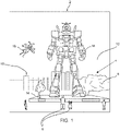
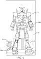
- an augmented reality scene 2 is depicted wherein a user of AR technology sees a real-world park-like setting 4 featuring people 6, trees 8, buildings 10, and sky 12 in the background, and a concrete platform 14.
- the user of the AR technology also perceives that he "sees" a robot 16 standing upon the real-world platform 14, and a cartoon-like avatar character 18 flying by which seems to be a personification of a bumble bee, even though these elements 16, 18 do not exist in the real world.
- the human visual perception system is very complex, and producing a VR or AR technology that facilitates a comfortable, natural-feeling, rich presentation of virtual image elements amongst other virtual or real-world imagery elements is challenging.
- VR and AR display systems can benefit from information regarding the head pose of a viewer or user (i.e., the orientation and/or location of user's head).
- head-worn displays or helmet-mounted displays, or smart glasses
- head-worn displays are at least loosely coupled to a user's head, and thus move when the user's head moves. If the user's head motions are detected by the display system, the data being displayed can be updated to take the change in head pose into account.
- a user wearing a head-worn display views a virtual representation of a three-dimensional (3D) object on the display and walks around the area where the 3D object appears, that 3D object can be re-rendered for each viewpoint, giving the user the perception that he or she is walking around an object that occupies real space.
- the head-worn display is used to present multiple objects within a virtual space (for instance, a rich virtual world)
- measurements of head pose can be used to re-render the scene to match the user's dynamically changing head location and orientation and provide an increased sense of immersion in the virtual space.
- Head-worn displays that enable AR (i.e., the concurrent viewing of real and virtual elements) can have several different types of configurations.
- a camera captures elements of a real scene
- a computing system superimposes virtual elements onto the captured real scene
- a nontransparent display presents the composite image to the eyes.
- Another configuration is often referred to as an "optical see-through” display, in which the user can see through transparent (or semi-transparent) elements in the display system to view directly the light from real objects in the environment.
- the transparent element often referred to as a "combiner,” superimposes light from the display over the user's view of the real world.
- the optical see-through AR display which allows the user to directly view ambient light from the real-world environment.
- the virtual objects that are superimposed over the real world be opaque, so that real objects or portions thereof behind the virtual objects from the user's perspective are completely obscured to provide a real world experience to the user.
- the virtual objects or portions thereof may appear transparent or translucent when overlapping real objects.
- the invention relates to a method of operating an augmented reality (AR) system according to claim 1.
- AR augmented reality
- the description that follows relates to display systems and methods to be used in augmented reality systems.
- the augmented reality system 100 provides images of virtual objects intermixed with physical objects in a field of view of an end user 50.
- the augmented reality system 100 and the various techniques taught herein, may be employed in applications other than augmented reality.
- various techniques may be applied to any projection or display system.
- the various techniques described herein may be applied to pico projectors where movement may be made by an end user's hand rather than the head.
- the teachings should not be limited to such systems of such uses.
- Virtual objects also referred to herein as virtual tags or tag or call outs, may take any of a large variety of forms, basically any variety of data, information, concept, or logical construct capable of being represented as an image.
- Non-limiting examples of virtual objects may include: a virtual text object, a virtual numeric object, a virtual alphanumeric object, a virtual tag object, a virtual field object, a virtual chart object, a virtual map object, a virtual instrumentation object, or a virtual visual representation of a physical object.
- the augmented reality system 100 is capable of ensuring or at least increasing the opaqueness of virtual objects that are displayed over real objects.
- the augmented reality system 100 accomplishes this by decreasing the contrast between the virtual objects and the real objects in the regions where they overlap by displaying additional interference images over the real objects and/or modifying the virtual image data prior to display of the virtual obj ects.
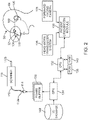
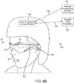
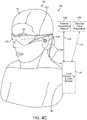
- the augmented reality system 100 comprises a frame structure 102 worn by an end user 50, a display system 104 carried by the frame structure 102, such that the display system 104 is positioned in front of the eyes 52 of the end user 50, and a speaker 106 carried by the frame structure 102, such that the speaker 106 is positioned adjacent the ear canal of the end user 50 (optionally, another speaker (not shown) is positioned adjacent the other ear canal of the end user 50 to provide for stereo/shapeable sound control).
- the display system 104 is designed to present the eyes 52 of the end user 50 with photo-based radiation patterns that can be comfortably perceived as augmentations to physical reality, with highlevels of image quality and three-dimensional perception, as well as being capable of presenting two-dimensional content.
- the display system 104 presents a sequence of frames at high frequency that provides the perception of a single coherent scene.
- the display system 104 is an "optical see-through" display through which the user can directly view light from real objects via transparent (or semi-transparent) elements.
- the transparent element often referred to as a "combiner," superimposes light from the display over the user's view of the real world.
- the display system 104 comprises a projection subsystem 108 and a partially transparent display surface 110 on which the projection subsystem 108 projects images.
- the display surface 110 is positioned in the end user's 50 field of view between the eyes 52 of the end user 50 and an ambient environment, such that direct light from the ambient environment is transmitted through the display surface 110 to the eyes 52 of the end user 50.
- the projection subsystem 108 includes one or more optical fibers 112 (e.g.
- the projection subsystem 108 may also include one or more light sources 114 that produces the light (e.g., emits light of different colors in defined patterns), and communicatively couples the light to the other end 112a of the optical fiber(s) 112.
- the light source(s) 114 may take any of a large variety of forms, for instance, a set of RGB lasers (e.g., laser diodes capable of outputting red, green, and blue light) operable to respectively produce red, green, and blue coherent collimated light according to defined pixel patterns specified in respective frames of pixel information or data.
- RGB lasers e.g., laser diodes capable of outputting red, green, and blue light
- Laser light provides high color saturation and are highly energy efficient.
- the display system 104 may further comprise a scanning device 116 that scans the optical fiber(s) 112 in a predetermined pattern in response to control signals.
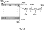
- a frame 118 of pixel information or data specifies pixel information or data to present an image, for example, an image of one or more virtual objects, according to one illustrated embodiment.
- the frame 118 is schematically illustrated with cells 120a-120m divided into horizontal rows or lines 122a-122n. Each cell 120 of the frame 118 may specify values for each of a plurality of colors for the respective pixel to which the cell 120 corresponds and/or intensities.
- the frame 118 may specify one or more values for red 124a, one or more values for green 124b, and one or more values for blue 124c for each pixel.
- the values 124 may be specified as binary representations for each of the colors, for instance, a respective 4-bit number for each color.
- Each cell 120 of the frame 118 may additionally include a value 124d in the form of a 4-bit number that specifies an intensity. Further details explaining an example of a display system 104 are provided in U.S. Provisional Patent Application Ser. No. 61/801,219 .
- the augmented reality system 100 further comprises one or more sensors (not shown) mounted to the frame structure 102 for detecting the position and movement of the head 54 of the end user 50 and/or the eye position and inter-ocular distance of the end user 50.
- sensors may include image capture devices (such as cameras), microphones, inertial measurement units, accelerometers, compasses, GPS units, radio devices, and/or gyros).
- the augmented reality system 100 comprises a head worn transducer system 126 that includes one or more inertial transducers to capture inertial measurements indicative of movement of the head 54 of the end user 50.
- the transducer system 126 may be used to sense, measure, or collect information about the head movements of the end user 50.
- the transducer system 126 may be used to detect measurement movements, speeds, acceleration, and/or positions of the head 54 of the end user 50.
- the augmented reality system 100 further comprises one or more forward facing cameras 128 that are affixed relative to the head 54 of the end user 50.
- the cameras 128 are mounted to the frame structure 102.
- the forward facing cameras 128 may be used to capture information about the environment in which the end user 50 is located.
- the forward facing cameras 128 may be used to capture information indicative of distance and orientation of the end user 50 with respect to that environment and specific objects in that environment.
- the forward facing cameras 128 are particularly suited to capture information indicative of distance and orientation of the head 54 of the end user 50 with respect to the environment in which the end user 50 is located and specific objects in that environment.
- the forward facing cameras 128 may, for example, be employed to detect head movement, speed, and/or acceleration of head movements.
- the forward facing cameras 128 may, for example, be employed to detect or infer a center of attention of the end user 50, for example, based at least in part on an orientation of the head 54 of the end user 50. Orientation may be detected in any direction (e.g., up/down, left, right with respect to the reference frame of the end user 50). More significantly, the forward cameras 128 capture image data of a three-dimensional scene in the ambient environment, which as will be further discussed below, can be used to determine the overlap between real objects and virtual objects from the perspective of the end user 50, and to analyze the color characteristics of the real objects in the overlap regions to facilitate reduction in the contrast between the real objects and virtual objects.
- the augmented reality system 100 further comprises a patient orientation detection module 130.
- the patient orientation module 130 detects the instantaneous position of the head 54 of the end user 50 and predicts the position of the head 54 of the end user 50 based on position data received from the sensor(s). In one embodiment, the patient orientation module 130 predicts the position of the head 54 based on predicting the end user's 50 shift in focus. For example, the patient orientation module 130 may select a virtual object based at least on input indicative of attention of the end user 50, and determine the location of appearance of a virtual object in a field of view of the end user 50 relative to the frame of reference of the end user 50.
- the patient orientation module 130 may employ estimated speed and/or estimated changes in speed or estimated acceleration to predict the position of the head 54 of the end user 50.
- the patient orientation module 130 may employ historical attributes of the end user 50 to predict the position of the head 54 of the end user 50. Further details describing predicting the head position of an end user 50 are set forth in U.S. Patent Application Ser. No. 61/801,219 .
- the augmented reality system 100 further comprises a control system that may take any of a large variety of forms.
- the control system includes a number of controllers, for instance one or more microcontrollers, microprocessors or central processing units (CPUs), digital signal processors, graphics processing units (GPUs), other integrated circuit controllers, such as application specific integrated circuits (ASICs), programmable gate arrays (PGAs), for instance field PGAs (FPGAs), and/or programmable logic controllers (PLUs).
- controllers for instance one or more microcontrollers, microprocessors or central processing units (CPUs), digital signal processors, graphics processing units (GPUs), other integrated circuit controllers, such as application specific integrated circuits (ASICs), programmable gate arrays (PGAs), for instance field PGAs (FPGAs), and/or programmable logic controllers (PLUs).
- CPUs central processing units
- ASICs application specific integrated circuits
- PGAs programmable gate arrays
- FPGAs field
- the control system of the augmented reality system 100 comprises a central processing unit (CPU) 132, a graphics processing unit (GPU) 134, and one or more frame buffers 136.
- the CPU 132 controls overall operation, while the GPU 134 renders frames (i.e., translating a three-dimensional scene into a two-dimensional image) from three-dimensional data stored in the remote data repository 150 and stores these frames in the frame buffer(s) 136.
- one or more additional integrated circuits may control the reading into and/or reading out of frames from the frame buffer(s) 136 and operation of the scanning device of the display system 104. Reading into and/or out of the frame buffer(s) 146 may employ dynamic addressing, for instance, where frames are overrendered.
- the augmented reality system 100 further comprises a read only memory (ROM) 138 and a random access memory (RAM) 140.
- the augmented reality system 100 further comprises a three-dimensional data base 142 from which the GPU 134 can access three-dimensional data of one or more scenes for rendering frames.
- the CPU 132 determines overlap regions between the virtual objects rendered by the GPU 132 and the real objects, analyzes the color characteristics of the real objects in these overlap regions, and decreases the contrast between the virtual objects and the real objects in these overlap regions based the analyzed color characteristics prior to display of the virtual objects to the end user 50.
- the various processing components of the augmented reality system 100 may be physically contained in a distributed system.
- the augmented reality system 100 comprises a local processing and data module 144 operatively coupled, such as by a wired lead or wireless connectivity 146, to the display system 104 and sensors.
- the local processing and data module 144 may be mounted in a variety of configurations, such as fixedly attached to the frame structure 102 ( Fig. 4A ), fixedly attached to a helmet or hat 56 ( Fig. 4B ), embedded in headphones, removably attached to the torso 58 of the end user 50 ( Fig.
- the augmented reality system 100 further comprises a remote processing module 148 and remote data repository 150 operatively coupled, such as by a wired lead or wireless connectivity 150, 152, to the local processing and data module 144, such that these remote modules 148, 150 are operatively coupled to each other and available as resources to the local processing and data module 144.
- the local processing and data module 144 may comprise a power-efficient processor or controller, as well as digital memory, such as flash memory, both of which may be utilized to assist in the processing, caching, and storage of data captured from the sensors and/or acquired and/or processed using the remote processing module 148 and/or remote data repository 150, possibly for passage to the display system 104 after such processing or retrieval.
- the remote processing module 148 may comprise one or more relatively powerful processors or controllers configured to analyze and process data and/or image information.
- the remote data repository 150 may comprise a relatively large-scale digital data storage facility, which may be available through the internet or other networking configuration in a "cloud" resource configuration. In one embodiment, all data is stored and all computation is performed in the local processing and data module 144, allowing fully autonomous use from any remote modules.
- the couplings 146, 152, 154 between the various components described above may include one or more wired interfaces or ports for providing wires or optical communications, or one or more wireless interfaces or ports, such as via RF, microwave, and IR for providing wireless communications.
- all communications may be wired, while in other implementations all communications may be wireless.
- the choice of wired and wireless communications may be different from that illustrated in Figs. 4A-4D . Thus, the particular choice of wired or wireless communications should not be considered limiting.
- the patient orientation module 130 is contained in the local processing and data module 144, while the CPU 132 and GPU 134 are contained in the remote processing module 148, although in alternative embodiments, the CPU 132, GPU 124, or portions thereof may be contained in the local processing and data module 144.
- the 3D database 142 can be associated with the remote data repository 150.
- the augmented reality system 100 compensates for the direct light from the real world over which the virtual objects are superimposed on the display surface 110.
- a first overlap region 200a in the display coincides with a portion of the right leg of the robot 16 and a portion of the buildings 10
- a second overlap region 200b in the display coincides with a portion of the left arm of the robot 16 and a portion of the sky 12.
- the right leg portion and the left arm portion of the robot 16 be opaque, such that the portions of the buildings 10 and sky 12 that are behind these robot statue portions cannot be seen by the end user 50.
- the locations of the overlap regions 200a and 200b in the display depend largely on the viewing perspective of the end user 50 and any movement of the virtual objects, and in this case, the robot 16.
- the overlap regions 200a and 200b will shift to the right in the display; if the end user 50 moves his or her head 54 to the right, the overlap regions 200a and 200b will shift to the left in the display; if the robot 16 moves to the left, the overlap regions 200a and 200b will shift to the left in the display; or if the robot 16 moves to the right, the overlap regions 200a and 200b will shift to the right in the display.
- the augmented reality system 100 compensates for the direct light from the real world by decreasing the perceived contrast (e.g., the color contrast and/or intensity contrast) between the real objects and the virtual objects in the overlap regions.
- the augmented reality system 100 may decrease the perceived contrast between the right leg of the robot 16 and the buildings 10 in the first overlap region 200a, and may decrease the perceived contrast between the left arm of the robot 16 and the sky 12 in the second overlap region 200b.
- the augmented reality system 100 may decrease the perceived contrast between the real objects and the virtual objects in the overlap regions in any one of a variety of ways.
- the augmented reality system 100 decreases the perceived contrast between the real objects and the virtual objects in the overlap regions by displaying over the real objects in the overlap regions an interference image that is separate from the virtual image.
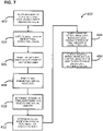
- the augmented reality system 100 allows the end user 50 to visualize direct light from the three-dimensional scene in an ambient environment, e.g., the real-world park-like setting 4 illustrated in Fig. 1 (step 302). In the illustrated embodiment, this is accomplished simply by allowing the direct light from the ambient environment to pass through the display surface 110 to the eyes 54 of the user 50.
- the CPU 132 directs the forward facing cameras 128 to capture image data of the three-dimensional scene 4 (step 304).
- the forward facing cameras 128 will typically be offset from the focal points of the end user 50.
- the forward facing cameras 128 may be affixed near the sides of the user's head 54.
- the CPU 132 warps the captured image data to the point of view of the user 50 (step 306).
- a two-dimensional parallax warping technique is performed on the captured image data.
- the CPU 132 instructs the GPU 134 to generate virtual image data from the point of the view of the end user 50, and in this embodiment, rendering the two-dimensional virtual image data from a three-dimensional virtual scene (step 308).
- the virtual image data may be generated based on predictive head positions in order to minimize any latency issues, e.g., by rendering and warping the virtual image data in the manner described in U.S. Patent Application Ser. No. 62/308,418 , entitled "Wide Baseline Stereo for Low-Latency Render".
- the CPU 132 determines regions of spatial overlap between real objects in the captured image data (to obtain the real objects in the three-dimensional scene 4) and virtual objects in the virtual image data (step 310), e.g., the overlap regions 200a and 200b, with the real objects being the buildings 10 and sky 12, and the virtual objects being the right leg and left arm of the robot 16.
- the CPU 132 can determine the overlap regions simply by comparing the locations of the pixels of the real objects and virtual objects, and identifying the locations that are common to the real and virtual object pixels.
- the CPU 132 determines the color characteristics of the real objects in the captured image data in the overlap regions in order to determine the color characteristics of the corresponding real objects perceived by the end user 50 in the overlap regions) (step 312).
- the captured image data and virtual image data comprise a plurality of pixels, each of which is defined by at least one value.
- the captured image data and virtual image data can be formed as frames of pixel data, such as those illustrated in Fig. 3 .
- each pixel may comprise a 4-bit number for each of a red, green, and blue color, and may further comprise a 4-bit number for intensity.
- the CPU 132 determines the color characteristics of the corresponding real objects in the captured image data by determining the color and/or intensity values of each of the pixels in the overlap regions.
- the CPU 132 decreases the perceived contrast (e.g., the perceived color contrast and/or perceived color intensity) between the real objects and the virtual objects in the overlap regions based on the determined color characteristics of the respective real objects in the overlap regions.
- the CPU 132 generates interference data based on the determined color characteristics of the real objects in the overlap regions (step 314), and instructs the display system 104 to display the interference data as an interference image over the overlap regions to the end user 50, such that the interference image combines with the direct light from the real objects to create a background for the virtual objects in the overlap regions (step 316).
- the backgrounds in the overlap regions have decreased dynamic color ranges relative to the real objects in the overlap regions; e.g., the backgrounds may have a generally uniform color, such as grey, in the overlap regions.
- the color of the real object in the overlap region 200a and in this case the color of the buildings 10, varies from a brownish color to a greenish color amongst the pixels, such that the buildings 10 have a relatively high dynamic color range in the overlap region 200a.
- the CPU 132 may decrease the perceived dynamic color range in the overlap region 200a by adding color to the buildings 10 on a pixel-by-pixel basis, such that the buildings 10 have a uniform grey color in the overlap region 200a.
- the CPU 132 may select a greyish hue for the background that has a color vector having values that are all greater than the respective values of the color vectors of the pixels of the buildings 10 for the background, and generate interference data that adds color to the pixels of the buildings 10, such that the background is the selected greyish hue.
- the CPU 132 may generate a first interference pixel having a color vector of [1, 68, 101] and a second interference pixel having a color vector of [129, 46, 106], which when added to the respective first and second pixels of the buildings 10 will equal [168, 168, 168].
- the first and second pixels of the interference image will combine with the corresponding first and second pixels of the buildings 10 to create a greyish background color for the corresponding first and second pixels of the virtual object (i.e., the right leg of the robot 16).
- the number of pixels in any particular overlap region will typically far exceed two, and thus, the number of interference pixels needs to be generated will likewise far exceed two.
- the CPU 132 adds intensity to the real objects in the overlap regions to match the intensity of the virtual objects in the overlap regions. For example, if the first pixel of the buildings 12 has an intensity value of 128, and the corresponding pixel value of the right leg of the robot 16 has an intensity value of 168, the CPU 132 may generate the first interference pixel with an intensity value of 40, which when combined with the intensity value of the first pixel of the buildings 12, creates a background pixel value of 168.
- the CPU 132 instructs the display system 104 to display the virtual image data as a virtual image to the end user 50 after the perceived contrast between the real objects and the virtual objects have been decreased that, along with the visualized direct light, creates a three-dimensional augmented scene (step 318). For example, if the perceived color of the buildings 10 in the overlap region 200a are a uniform grey (after compensation using the interference image), the right leg of the robot 16 will presumably be opaque when displayed over the buildings 10 in the overlap region 200a.
- the virtual image may be simultaneously displayed with the interference image, in which case, different optical fibers 112 may be respectively used to display the virtual image and interference image; or the virtual image may be displayed very soon after the interference image is displayed, in which case, the same optical fiber 112 may be used to sequentially display the virtual image and interference image at time that are spaced close enough together, such that the end user 50 simultaneously perceives the virtual image and interference image.
- the augmented reality system 100 may alternatively decrease the perceived contrast between the real objects and the virtual objects in the overlap regions by modifying the virtual objects in the overlap regions.
- the augmented reality system 100 allows the end user 50 to visualize direct light from the three-dimensional scene in an ambient environment, e.g., the real-world park-like setting 4 illustrated in Fig. 1 (step 402), directs the forward facing cameras 128 to capture image data of the three-dimensional scene 4 (step 404), warps the captured image data to the point of view of the user 50 (step 406), instructs the GPU 134 to generate virtual image data from the point of the view of the end user 50 (step 408), determines regions of spatial overlap between real objects in the captured image data (to obtain the real objects in the three-dimensional scene 4) and virtual objects in the virtual image data (step 410), and determines the color characteristics of the real objects in the captured image data in the overlap regions (to determine the color characteristics of the corresponding real objects in the overlap regions) (step 412).
- the end user 50 to visualize direct light from the three-dimensional scene in an ambient environment, e.g., the real-world park-like setting 4 illustrated in Fig. 1 (step 402), directs
- the CPU 132 next decreases the perceived contrast (e.g., the perceived color contrast and/or perceived color intensity) between the real objects and the virtual objects in the overlap regions based on the determined color characteristics of the respective real objects in the overlap regions.
- the CPU 132 modifies the virtual image data based on the determined color characteristics of the real objects in the overlap regions (step 414).
- the CPU 132 modifies the virtual image data such that all color is removed from the perceived real objects in the overlap regions.
- color may be subtracted from the original virtual image data, which subtracted color is used to make the real objects black in the overlap regions.
- the color vectors of the pixels of the real objects in the overlap regions may be subtracted from color vectors of the corresponding pixels of the virtual objects in the overlap regions to obtain the color vectors of the pixels for the modified virtual image data to be used for the virtual objects.
- combining the pixels of the modified virtual objects with the corresponding pixels of the real objects will yield the original virtual objects.
- a first pixel of the buildings 10 in the overlap region 200 has a color vector of [167, 100, 67] (i.e., the 4-bit binary value for the red, green, and blue respectively equals 167, 100, 67)
- a second pixel of the buildings 10 has a color vector of [39, 122, 62] (i.e., the 4-bit binary value for the red, green, and blue respectively equals 39, 122, 62)
- a corresponding first pixel of the right leg of the robot 16 has a color vector of [185, 123, 80] (i.e., the 4-bit binary value for the red, green, and blue respectively equals 185, 123, 80)
- a corresponding second pixel of the right leg of the robot 16 has a color vector of [65, 140, 80] (i.e., the 4-bit binary value for the red, green, and blue respectively equals 65, 140, 80)
- the CPU 132 may modify the first and second pixels of the right leg of the robot 16
- the CPU 132 instructs the display system 104 to display the virtual image data as a virtual image to the end user 50 after the perceived contrast between the real objects and the virtual objects have been decreased that, along with the visualized direct light, creates a three-dimensional augmented scene (step 416).
- the augmented reality system 100 may alternatively decrease the perceived contrast between the real objects and the virtual objects in the overlap regions by both displaying an interference image over the real objects in the overlap regions and modifying the virtual objects in the overlap regions.
- the augmented reality system 100 allows the end user 50 to visualize direct light from the three-dimensional scene in an ambient environment, e.g., the real-world park-like setting 4 illustrated in Fig. 1 (step 502), directs the forward facing cameras 128 to capture image data of the three-dimensional scene 4 (step 504), warps the captured image data to the point of view of the user 50 (step 506), instructs the GPU 134 to generate virtual image data from the point of the view of the end user 50 (step 508), determines regions of spatial overlap between real objects in the captured image data (to obtain the real objects in the three-dimensional scene 4) and virtual objects in the virtual image data (step 510), and determines the color characteristics of the real objects in the captured image data in the overlap regions (to determine the color characteristics of the corresponding real objects in the overlap regions) (step 512).
- an ambient environment e.g., the real-world park-like setting 4 illustrated in Fig. 1
- step 504 directs the forward facing cameras 128 to capture image data of the three-dimensional
- the CPU 132 next decreases the perceived contrast (e.g., the perceived color contrast and/or perceived color intensity) between the real objects and the virtual objects in the overlap regions based on the determined color characteristics of the respective real objects in the overlap regions.
- the CPU 132 will generate interference data for a first set of the overlap regions or portions thereof (step 512), and will modify the virtual image data for a second different set of the overlap regions or portions thereof (step 514).
- the CPU 132 will generate interference data, and for those portions of the overlap regions where displaying an interference image over the real object will not potentially decrease the contrast between that real object and the virtual object (i.e., adding color to the real object will increase the perceived contrast), the CPU 132 will modify the virtual image data instead of generating interference data.
- the first pixel of the buildings 10 has a color vector of [167, 100, 67] (i.e., the 4-bit binary value for the red, green, and blue is respectively 167, 100, 67)
- the second pixel of the buildings 10 has a color vector of [185, 125, 139] (i.e., the 4-bit binary value for the red, green, and blue is respectively 185, 125, 139)
- a corresponding first pixel of the right leg of the robot 16 has a color vector of [185, 123, 80] (i.e., the 4-bit binary value for the red, green, and blue is respectively 185, 123, 80)
- a corresponding second pixel of the right leg of the robot 16 has a color vector of [39, 122, 62] (i.e., the 4-bit binary value for the red, green, and blue is respectively 39, 122, 62)
- the selected color vector for the background is [168, 168, 168] (i.e., the 4-
- the CPU 132 may determine that color can be added to the first pixel of the buildings 10 to obtain the selected background. That is, all of the values in the color vector for the first pixel of the buildings 10 are below the values of the selected background color vector. Thus, the CPU 132 may generate a first interference pixel having a color vector of [1, 68,101], which when added to the first pixel of the buildings 10, will equal [168, 168, 168]. In contrast, the CPU 132 may determine that color cannot be added to the second pixel of the buildings 10 to obtain the selected background. That is, at least one of the values in the color vector for the second pixel is not below the corresponding value(s) of the selected background color vector.
- the CPU 132 may modify the second pixel of the right leg of the robot 16 to have a color vector [26, 18, 18].
- the CPU 132 instructs the display system 104 to display the interference data as an interference image over the first set of overlap regions or portions thereof to the end user 50, such that the interference image combines with the direct light from the real objects to create a background for the virtual objects in the first set of overlap regions or portions thereof (step 518), and instructs the display system 104 to display the virtual image data as a virtual image to the end user 50 after the perceived contrast between the real objects and the virtual objects have been decreased that, along with the visualized direct light, creates a three-dimensional augmented scene (step 520).
- the unmodified virtual image data will be displayed over the first set of overlap regions or portions thereof (i.e., the portions over which the interference image is displayed), and the modified virtual image data will be displayed over the second set of overlap regions or portions thereof (i.e., the portions over which the interference image is not displayed).
Landscapes
- Engineering & Computer Science (AREA)
- Physics & Mathematics (AREA)
- General Physics & Mathematics (AREA)
- Theoretical Computer Science (AREA)
- Computer Graphics (AREA)
- Computer Hardware Design (AREA)
- General Engineering & Computer Science (AREA)
- Software Systems (AREA)
- Architecture (AREA)
- Processing Or Creating Images (AREA)
- Controls And Circuits For Display Device (AREA)
- Optical Communication System (AREA)
Priority Applications (1)
| Application Number | Priority Date | Filing Date | Title |
|---|---|---|---|
| EP22204618.7A EP4156167B1 (en) | 2016-03-15 | 2017-03-15 | Direct light compensation technique for augmented reality system |
Applications Claiming Priority (2)
| Application Number | Priority Date | Filing Date | Title |
|---|---|---|---|
| US201662308433P | 2016-03-15 | 2016-03-15 | |
| PCT/US2017/022578 WO2017161039A1 (en) | 2016-03-15 | 2017-03-15 | Direct light compensation technique for augmented reality system |
Related Child Applications (2)
| Application Number | Title | Priority Date | Filing Date |
|---|---|---|---|
| EP22204618.7A Division EP4156167B1 (en) | 2016-03-15 | 2017-03-15 | Direct light compensation technique for augmented reality system |
| EP22204618.7A Division-Into EP4156167B1 (en) | 2016-03-15 | 2017-03-15 | Direct light compensation technique for augmented reality system |
Publications (3)
| Publication Number | Publication Date |
|---|---|
| EP3430610A1 EP3430610A1 (en) | 2019-01-23 |
| EP3430610A4 EP3430610A4 (en) | 2019-02-06 |
| EP3430610B1 true EP3430610B1 (en) | 2022-12-07 |
Family
ID=59847083
Family Applications (2)
| Application Number | Title | Priority Date | Filing Date |
|---|---|---|---|
| EP17767470.2A Active EP3430610B1 (en) | 2016-03-15 | 2017-03-15 | Direct light compensation technique for augmented reality system |
| EP22204618.7A Active EP4156167B1 (en) | 2016-03-15 | 2017-03-15 | Direct light compensation technique for augmented reality system |
Family Applications After (1)
| Application Number | Title | Priority Date | Filing Date |
|---|---|---|---|
| EP22204618.7A Active EP4156167B1 (en) | 2016-03-15 | 2017-03-15 | Direct light compensation technique for augmented reality system |
Country Status (10)
| Country | Link |
|---|---|
| US (2) | US10628996B2 (enExample) |
| EP (2) | EP3430610B1 (enExample) |
| JP (2) | JP6750025B2 (enExample) |
| KR (1) | KR102180060B1 (enExample) |
| CN (2) | CN116485929B (enExample) |
| AU (2) | AU2017232527A1 (enExample) |
| CA (1) | CA3016344A1 (enExample) |
| IL (2) | IL261478B (enExample) |
| NZ (2) | NZ745790A (enExample) |
| WO (1) | WO2017161039A1 (enExample) |
Families Citing this family (27)
| Publication number | Priority date | Publication date | Assignee | Title |
|---|---|---|---|---|
| WO2017161039A1 (en) * | 2016-03-15 | 2017-09-21 | Magic Leap, Inc. | Direct light compensation technique for augmented reality system |
| US10290120B2 (en) * | 2017-03-20 | 2019-05-14 | SK Commercial Construction, Inc. | Color analysis and control using an electronic mobile device transparent display screen |
| US10803988B2 (en) * | 2017-03-20 | 2020-10-13 | SK Commercial Construction, Inc. | Color analysis and control using a transparent display screen on a mobile device with non-transparent, bendable display screen or multiple display screen with 3D sensor for telemedicine diagnosis and treatment |
| EP3626403B1 (en) * | 2017-05-17 | 2024-09-18 | Telexistence Inc. | Sensation imparting device, robot control system, and robot control method and program |
| US10859834B2 (en) | 2017-07-03 | 2020-12-08 | Holovisions | Space-efficient optical structures for wide field-of-view augmented reality (AR) eyewear |
| US10338400B2 (en) | 2017-07-03 | 2019-07-02 | Holovisions LLC | Augmented reality eyewear with VAPE or wear technology |
| KR102591582B1 (ko) * | 2018-06-22 | 2023-10-19 | 삼성전자주식회사 | 컨텐츠를 표시하는 방법 및 전자 장치 |
| TWI675583B (zh) * | 2018-07-23 | 2019-10-21 | 緯創資通股份有限公司 | 擴增實境系統及其色彩補償方法 |
| US10909373B1 (en) * | 2018-08-24 | 2021-02-02 | Snap Inc. | Augmented reality system using structured light |
| CN111818326B (zh) * | 2019-04-12 | 2022-01-28 | 广东虚拟现实科技有限公司 | 图像处理方法、装置、系统、终端设备及存储介质 |
| US11004269B2 (en) * | 2019-04-22 | 2021-05-11 | Microsoft Technology Licensing, Llc | Blending virtual environments with situated physical reality |
| WO2020237194A1 (en) * | 2019-05-22 | 2020-11-26 | Pcms Holdings, Inc. | Method for rendering of augmented reality content in combination with external display |
| US11216920B2 (en) * | 2019-05-31 | 2022-01-04 | Apple Inc. | Enhanced local contrast |
| CN112241199B (zh) * | 2019-07-19 | 2023-03-24 | 华为技术有限公司 | 虚拟现实场景中的交互方法及装置 |
| EP3819699B1 (en) * | 2019-11-08 | 2024-02-21 | Leica Instruments (Singapore) Pte. Ltd. | Optical system and corresponding apparatus, method and computer program |
| US11645756B2 (en) * | 2019-11-14 | 2023-05-09 | Samsung Electronics Co., Ltd. | Image processing apparatus and method |
| US11545108B2 (en) * | 2020-02-03 | 2023-01-03 | Apple Inc. | Modifying rendered image data based on ambient light from a physical environment |
| US11423621B1 (en) * | 2020-05-21 | 2022-08-23 | Facebook Technologies, Llc. | Adaptive rendering in artificial reality environments |
| CN111832104B (zh) * | 2020-06-24 | 2023-07-28 | 深圳市万翼数字技术有限公司 | 三维设备模型的建立方法及相关设备 |
| US11715405B1 (en) * | 2021-02-10 | 2023-08-01 | Sivalogeswaran Ratnasingam | Chroma modification based on ambient light characteristics |
| US12033556B1 (en) * | 2021-02-10 | 2024-07-09 | Sivalogeswaran Ratnasingam | Per-pixel color correction based on ambient light characteristics |
| US12003859B2 (en) * | 2021-07-16 | 2024-06-04 | Samsung Electronics Co., Ltd. | Brightness adjustment method, and apparatus thereof |
| KR20230103379A (ko) | 2021-12-31 | 2023-07-07 | 삼성전자주식회사 | Ar 처리 방법 및 장치 |
| CN114419293B (zh) * | 2022-01-26 | 2023-06-06 | 广州鼎飞航空科技有限公司 | 一种增强现实的数据处理方法、装置及设备 |
| WO2024059755A1 (en) * | 2022-09-14 | 2024-03-21 | Apple Inc. | Methods for depth conflict mitigation in a three-dimensional environment |
| CN116883607B (zh) * | 2023-09-06 | 2023-12-05 | 四川物通科技有限公司 | 基于辐射传输的虚拟现实场景生成系统 |
| CN119359977A (zh) * | 2024-10-14 | 2025-01-24 | 东南大学 | 一种基于增强现实显示设备测量对比敏感度的方法 |
Citations (1)
| Publication number | Priority date | Publication date | Assignee | Title |
|---|---|---|---|---|
| US20110279355A1 (en) * | 2009-01-27 | 2011-11-17 | Brother Kogyo Kabushiki Kaisha | Head mounted display |
Family Cites Families (19)
| Publication number | Priority date | Publication date | Assignee | Title |
|---|---|---|---|---|
| JP3450792B2 (ja) | 1999-03-25 | 2003-09-29 | キヤノン株式会社 | 奥行き画像計測装置及び方法、並びに複合現実感提示システム |
| JP2002148559A (ja) * | 2000-11-15 | 2002-05-22 | Mixed Reality Systems Laboratory Inc | 画像観察装置及びそれを用いた画像観察システム |
| CA2747544C (en) * | 2008-12-19 | 2016-06-21 | Saab Ab | System and method for mixing a scene with a virtual scenario |
| US8107084B2 (en) | 2009-01-30 | 2012-01-31 | Zygo Corporation | Interference microscope with scan motion detection using fringe motion in monitor patterns |
| US9323325B2 (en) * | 2011-08-30 | 2016-04-26 | Microsoft Technology Licensing, Llc | Enhancing an object of interest in a see-through, mixed reality display device |
| US8670000B2 (en) * | 2011-09-12 | 2014-03-11 | Google Inc. | Optical display system and method with virtual image contrast control |
| US9734633B2 (en) * | 2012-01-27 | 2017-08-15 | Microsoft Technology Licensing, Llc | Virtual environment generating system |
| US9147111B2 (en) * | 2012-02-10 | 2015-09-29 | Microsoft Technology Licensing, Llc | Display with blocking image generation |
| CN103472909B (zh) * | 2012-04-10 | 2017-04-12 | 微软技术许可有限责任公司 | 用于头戴式、增强现实显示器的逼真遮挡 |
| US20130328925A1 (en) * | 2012-06-12 | 2013-12-12 | Stephen G. Latta | Object focus in a mixed reality environment |
| US9430055B2 (en) * | 2012-06-15 | 2016-08-30 | Microsoft Technology Licensing, Llc | Depth of field control for see-thru display |
| US9158114B2 (en) * | 2012-11-05 | 2015-10-13 | Exelis Inc. | Image display utilizing a variable mask to selectively block image data |
| JP6273677B2 (ja) | 2013-02-28 | 2018-02-07 | セイコーエプソン株式会社 | 頭部装着型表示装置および頭部装着型表示装置の制御方法 |
| WO2014156033A1 (en) * | 2013-03-26 | 2014-10-02 | Seiko Epson Corporation | Head-mounted display device, control method of head-mounted display device, and display system |
| CN106133796B (zh) * | 2014-03-25 | 2019-07-16 | 苹果公司 | 用于在真实环境的视图中表示虚拟对象的方法和系统 |
| US10816798B2 (en) * | 2014-07-18 | 2020-10-27 | Vuzix Corporation | Near-eye display with self-emitting microdisplay engine |
| US10750153B2 (en) * | 2014-09-22 | 2020-08-18 | Samsung Electronics Company, Ltd. | Camera system for three-dimensional video |
| CN107111366B (zh) * | 2014-12-22 | 2020-10-30 | 依视路国际公司 | 用于使感觉输出装置的感觉输出模式与使用者适配的方法 |
| WO2017161039A1 (en) * | 2016-03-15 | 2017-09-21 | Magic Leap, Inc. | Direct light compensation technique for augmented reality system |
-
2017
- 2017-03-15 WO PCT/US2017/022578 patent/WO2017161039A1/en not_active Ceased
- 2017-03-15 NZ NZ745790A patent/NZ745790A/en not_active IP Right Cessation
- 2017-03-15 EP EP17767470.2A patent/EP3430610B1/en active Active
- 2017-03-15 CN CN202310452721.5A patent/CN116485929B/zh active Active
- 2017-03-15 JP JP2018548381A patent/JP6750025B2/ja active Active
- 2017-03-15 KR KR1020187029599A patent/KR102180060B1/ko active Active
- 2017-03-15 EP EP22204618.7A patent/EP4156167B1/en active Active
- 2017-03-15 CA CA3016344A patent/CA3016344A1/en active Pending
- 2017-03-15 NZ NZ786033A patent/NZ786033A/en not_active IP Right Cessation
- 2017-03-15 CN CN201780017089.4A patent/CN108780578B/zh active Active
- 2017-03-15 US US15/460,009 patent/US10628996B2/en active Active
- 2017-03-15 AU AU2017232527A patent/AU2017232527A1/en not_active Abandoned
-
2018
- 2018-08-30 IL IL261478A patent/IL261478B/en unknown
-
2020
- 2020-03-08 US US16/812,343 patent/US11257285B2/en active Active
- 2020-08-12 JP JP2020136187A patent/JP7054406B2/ja active Active
-
2021
- 2021-10-18 IL IL287369A patent/IL287369B2/en unknown
-
2022
- 2022-03-09 AU AU2022201635A patent/AU2022201635A1/en not_active Abandoned
Patent Citations (1)
| Publication number | Priority date | Publication date | Assignee | Title |
|---|---|---|---|---|
| US20110279355A1 (en) * | 2009-01-27 | 2011-11-17 | Brother Kogyo Kabushiki Kaisha | Head mounted display |
Also Published As
| Publication number | Publication date |
|---|---|
| EP4156167A1 (en) | 2023-03-29 |
| KR102180060B1 (ko) | 2020-11-17 |
| KR20180122690A (ko) | 2018-11-13 |
| JP2019517012A (ja) | 2019-06-20 |
| EP3430610A1 (en) | 2019-01-23 |
| US20200211273A1 (en) | 2020-07-02 |
| CN108780578B (zh) | 2023-05-26 |
| US10628996B2 (en) | 2020-04-21 |
| JP6750025B2 (ja) | 2020-09-02 |
| WO2017161039A1 (en) | 2017-09-21 |
| CN108780578A (zh) | 2018-11-09 |
| NZ786033A (en) | 2023-04-28 |
| AU2022201635A1 (en) | 2022-03-31 |
| NZ745790A (en) | 2023-04-28 |
| IL287369B2 (en) | 2023-06-01 |
| IL287369A (en) | 2021-12-01 |
| CA3016344A1 (en) | 2017-09-21 |
| US20170270707A1 (en) | 2017-09-21 |
| JP7054406B2 (ja) | 2022-04-13 |
| AU2017232527A1 (en) | 2018-09-20 |
| CN116485929B (zh) | 2024-07-26 |
| US11257285B2 (en) | 2022-02-22 |
| IL261478B (en) | 2021-12-01 |
| EP4156167B1 (en) | 2025-08-06 |
| IL261478A (en) | 2018-10-31 |
| JP2020198115A (ja) | 2020-12-10 |
| CN116485929A (zh) | 2023-07-25 |
| EP3430610A4 (en) | 2019-02-06 |
Similar Documents
| Publication | Publication Date | Title |
|---|---|---|
| US11257285B2 (en) | Direct light compensation technique for augmented reality system | |
| US10313661B2 (en) | Wide baseline stereo for low-latency rendering | |
| JP7036879B2 (ja) | 仮想画像生成システムにおけるテキストをより効率的に表示するための技法 | |
| CA3054619A1 (en) | Mixed reality system with virtual content warping and method of generating virtual content using same | |
| NZ738277B2 (en) | Technique for more efficiently displaying text in virtual image generation system |
Legal Events
| Date | Code | Title | Description |
|---|---|---|---|
| STAA | Information on the status of an ep patent application or granted ep patent |
Free format text: STATUS: THE INTERNATIONAL PUBLICATION HAS BEEN MADE |
|
| PUAI | Public reference made under article 153(3) epc to a published international application that has entered the european phase |
Free format text: ORIGINAL CODE: 0009012 |
|
| STAA | Information on the status of an ep patent application or granted ep patent |
Free format text: STATUS: REQUEST FOR EXAMINATION WAS MADE |
|
| 17P | Request for examination filed |
Effective date: 20181003 |
|
| AK | Designated contracting states |
Kind code of ref document: A1 Designated state(s): AL AT BE BG CH CY CZ DE DK EE ES FI FR GB GR HR HU IE IS IT LI LT LU LV MC MK MT NL NO PL PT RO RS SE SI SK SM TR |
|
| AX | Request for extension of the european patent |
Extension state: BA ME |
|
| A4 | Supplementary search report drawn up and despatched |
Effective date: 20190109 |
|
| RIC1 | Information provided on ipc code assigned before grant |
Ipc: G06T 15/10 20110101ALI20190103BHEP Ipc: H04N 13/00 20180101ALI20190103BHEP Ipc: G06T 17/10 20060101ALI20190103BHEP Ipc: G09G 5/04 20060101ALI20190103BHEP Ipc: G09G 5/02 20060101AFI20190103BHEP |
|
| RIC1 | Information provided on ipc code assigned before grant |
Ipc: H04N 13/00 20180101ALI20190103BHEP Ipc: G09G 5/02 20060101AFI20190103BHEP Ipc: G06T 15/10 20110101ALI20190103BHEP Ipc: G09G 5/04 20060101ALI20190103BHEP Ipc: G06T 17/10 20060101ALI20190103BHEP |
|
| DAV | Request for validation of the european patent (deleted) | ||
| DAX | Request for extension of the european patent (deleted) | ||
| STAA | Information on the status of an ep patent application or granted ep patent |
Free format text: STATUS: EXAMINATION IS IN PROGRESS |
|
| 17Q | First examination report despatched |
Effective date: 20200807 |
|
| GRAP | Despatch of communication of intention to grant a patent |
Free format text: ORIGINAL CODE: EPIDOSNIGR1 |
|
| STAA | Information on the status of an ep patent application or granted ep patent |
Free format text: STATUS: GRANT OF PATENT IS INTENDED |
|
| INTG | Intention to grant announced |
Effective date: 20220624 |
|
| GRAS | Grant fee paid |
Free format text: ORIGINAL CODE: EPIDOSNIGR3 |
|
| GRAA | (expected) grant |
Free format text: ORIGINAL CODE: 0009210 |
|
| STAA | Information on the status of an ep patent application or granted ep patent |
Free format text: STATUS: THE PATENT HAS BEEN GRANTED |
|
| AK | Designated contracting states |
Kind code of ref document: B1 Designated state(s): AL AT BE BG CH CY CZ DE DK EE ES FI FR GB GR HR HU IE IS IT LI LT LU LV MC MK MT NL NO PL PT RO RS SE SI SK SM TR |
|
| REG | Reference to a national code |
Ref country code: GB Ref legal event code: FG4D |
|
| REG | Reference to a national code |
Ref country code: CH Ref legal event code: EP Ref country code: AT Ref legal event code: REF Ref document number: 1536775 Country of ref document: AT Kind code of ref document: T Effective date: 20221215 |
|
| REG | Reference to a national code |
Ref country code: DE Ref legal event code: R096 Ref document number: 602017064389 Country of ref document: DE |
|
| REG | Reference to a national code |
Ref country code: IE Ref legal event code: FG4D |
|
| REG | Reference to a national code |
Ref country code: NL Ref legal event code: FP |
|
| REG | Reference to a national code |
Ref country code: LT Ref legal event code: MG9D |
|
| PG25 | Lapsed in a contracting state [announced via postgrant information from national office to epo] |
Ref country code: SE Free format text: LAPSE BECAUSE OF FAILURE TO SUBMIT A TRANSLATION OF THE DESCRIPTION OR TO PAY THE FEE WITHIN THE PRESCRIBED TIME-LIMIT Effective date: 20221207 Ref country code: NO Free format text: LAPSE BECAUSE OF FAILURE TO SUBMIT A TRANSLATION OF THE DESCRIPTION OR TO PAY THE FEE WITHIN THE PRESCRIBED TIME-LIMIT Effective date: 20230307 Ref country code: LT Free format text: LAPSE BECAUSE OF FAILURE TO SUBMIT A TRANSLATION OF THE DESCRIPTION OR TO PAY THE FEE WITHIN THE PRESCRIBED TIME-LIMIT Effective date: 20221207 Ref country code: FI Free format text: LAPSE BECAUSE OF FAILURE TO SUBMIT A TRANSLATION OF THE DESCRIPTION OR TO PAY THE FEE WITHIN THE PRESCRIBED TIME-LIMIT Effective date: 20221207 Ref country code: ES Free format text: LAPSE BECAUSE OF FAILURE TO SUBMIT A TRANSLATION OF THE DESCRIPTION OR TO PAY THE FEE WITHIN THE PRESCRIBED TIME-LIMIT Effective date: 20221207 |
|
| REG | Reference to a national code |
Ref country code: AT Ref legal event code: MK05 Ref document number: 1536775 Country of ref document: AT Kind code of ref document: T Effective date: 20221207 |
|
| PG25 | Lapsed in a contracting state [announced via postgrant information from national office to epo] |
Ref country code: RS Free format text: LAPSE BECAUSE OF FAILURE TO SUBMIT A TRANSLATION OF THE DESCRIPTION OR TO PAY THE FEE WITHIN THE PRESCRIBED TIME-LIMIT Effective date: 20221207 Ref country code: PL Free format text: LAPSE BECAUSE OF FAILURE TO SUBMIT A TRANSLATION OF THE DESCRIPTION OR TO PAY THE FEE WITHIN THE PRESCRIBED TIME-LIMIT Effective date: 20221207 Ref country code: LV Free format text: LAPSE BECAUSE OF FAILURE TO SUBMIT A TRANSLATION OF THE DESCRIPTION OR TO PAY THE FEE WITHIN THE PRESCRIBED TIME-LIMIT Effective date: 20221207 Ref country code: HR Free format text: LAPSE BECAUSE OF FAILURE TO SUBMIT A TRANSLATION OF THE DESCRIPTION OR TO PAY THE FEE WITHIN THE PRESCRIBED TIME-LIMIT Effective date: 20221207 Ref country code: GR Free format text: LAPSE BECAUSE OF FAILURE TO SUBMIT A TRANSLATION OF THE DESCRIPTION OR TO PAY THE FEE WITHIN THE PRESCRIBED TIME-LIMIT Effective date: 20230308 |
|
| P01 | Opt-out of the competence of the unified patent court (upc) registered |
Effective date: 20230607 |
|
| PG25 | Lapsed in a contracting state [announced via postgrant information from national office to epo] |
Ref country code: SM Free format text: LAPSE BECAUSE OF FAILURE TO SUBMIT A TRANSLATION OF THE DESCRIPTION OR TO PAY THE FEE WITHIN THE PRESCRIBED TIME-LIMIT Effective date: 20221207 Ref country code: RO Free format text: LAPSE BECAUSE OF FAILURE TO SUBMIT A TRANSLATION OF THE DESCRIPTION OR TO PAY THE FEE WITHIN THE PRESCRIBED TIME-LIMIT Effective date: 20221207 Ref country code: PT Free format text: LAPSE BECAUSE OF FAILURE TO SUBMIT A TRANSLATION OF THE DESCRIPTION OR TO PAY THE FEE WITHIN THE PRESCRIBED TIME-LIMIT Effective date: 20230410 Ref country code: EE Free format text: LAPSE BECAUSE OF FAILURE TO SUBMIT A TRANSLATION OF THE DESCRIPTION OR TO PAY THE FEE WITHIN THE PRESCRIBED TIME-LIMIT Effective date: 20221207 Ref country code: CZ Free format text: LAPSE BECAUSE OF FAILURE TO SUBMIT A TRANSLATION OF THE DESCRIPTION OR TO PAY THE FEE WITHIN THE PRESCRIBED TIME-LIMIT Effective date: 20221207 Ref country code: AT Free format text: LAPSE BECAUSE OF FAILURE TO SUBMIT A TRANSLATION OF THE DESCRIPTION OR TO PAY THE FEE WITHIN THE PRESCRIBED TIME-LIMIT Effective date: 20221207 |
|
| PG25 | Lapsed in a contracting state [announced via postgrant information from national office to epo] |
Ref country code: SK Free format text: LAPSE BECAUSE OF FAILURE TO SUBMIT A TRANSLATION OF THE DESCRIPTION OR TO PAY THE FEE WITHIN THE PRESCRIBED TIME-LIMIT Effective date: 20221207 Ref country code: IS Free format text: LAPSE BECAUSE OF FAILURE TO SUBMIT A TRANSLATION OF THE DESCRIPTION OR TO PAY THE FEE WITHIN THE PRESCRIBED TIME-LIMIT Effective date: 20230407 Ref country code: AL Free format text: LAPSE BECAUSE OF FAILURE TO SUBMIT A TRANSLATION OF THE DESCRIPTION OR TO PAY THE FEE WITHIN THE PRESCRIBED TIME-LIMIT Effective date: 20221207 |
|
| REG | Reference to a national code |
Ref country code: DE Ref legal event code: R097 Ref document number: 602017064389 Country of ref document: DE |
|
| PLBE | No opposition filed within time limit |
Free format text: ORIGINAL CODE: 0009261 |
|
| STAA | Information on the status of an ep patent application or granted ep patent |
Free format text: STATUS: NO OPPOSITION FILED WITHIN TIME LIMIT |
|
| PG25 | Lapsed in a contracting state [announced via postgrant information from national office to epo] |
Ref country code: MC Free format text: LAPSE BECAUSE OF FAILURE TO SUBMIT A TRANSLATION OF THE DESCRIPTION OR TO PAY THE FEE WITHIN THE PRESCRIBED TIME-LIMIT Effective date: 20221207 Ref country code: DK Free format text: LAPSE BECAUSE OF FAILURE TO SUBMIT A TRANSLATION OF THE DESCRIPTION OR TO PAY THE FEE WITHIN THE PRESCRIBED TIME-LIMIT Effective date: 20221207 |
|
| REG | Reference to a national code |
Ref country code: CH Ref legal event code: PL |
|
| 26N | No opposition filed |
Effective date: 20230908 |
|
| PG25 | Lapsed in a contracting state [announced via postgrant information from national office to epo] |
Ref country code: SI Free format text: LAPSE BECAUSE OF FAILURE TO SUBMIT A TRANSLATION OF THE DESCRIPTION OR TO PAY THE FEE WITHIN THE PRESCRIBED TIME-LIMIT Effective date: 20221207 |
|
| PG25 | Lapsed in a contracting state [announced via postgrant information from national office to epo] |
Ref country code: LU Free format text: LAPSE BECAUSE OF NON-PAYMENT OF DUE FEES Effective date: 20230315 |
|
| REG | Reference to a national code |
Ref country code: IE Ref legal event code: MM4A |
|
| PG25 | Lapsed in a contracting state [announced via postgrant information from national office to epo] |
Ref country code: LI Free format text: LAPSE BECAUSE OF NON-PAYMENT OF DUE FEES Effective date: 20230331 Ref country code: IE Free format text: LAPSE BECAUSE OF NON-PAYMENT OF DUE FEES Effective date: 20230315 Ref country code: CH Free format text: LAPSE BECAUSE OF NON-PAYMENT OF DUE FEES Effective date: 20230331 |
|
| PG25 | Lapsed in a contracting state [announced via postgrant information from national office to epo] |
Ref country code: IT Free format text: LAPSE BECAUSE OF FAILURE TO SUBMIT A TRANSLATION OF THE DESCRIPTION OR TO PAY THE FEE WITHIN THE PRESCRIBED TIME-LIMIT Effective date: 20221207 |
|
| PG25 | Lapsed in a contracting state [announced via postgrant information from national office to epo] |
Ref country code: BG Free format text: LAPSE BECAUSE OF FAILURE TO SUBMIT A TRANSLATION OF THE DESCRIPTION OR TO PAY THE FEE WITHIN THE PRESCRIBED TIME-LIMIT Effective date: 20221207 |
|
| PG25 | Lapsed in a contracting state [announced via postgrant information from national office to epo] |
Ref country code: BG Free format text: LAPSE BECAUSE OF FAILURE TO SUBMIT A TRANSLATION OF THE DESCRIPTION OR TO PAY THE FEE WITHIN THE PRESCRIBED TIME-LIMIT Effective date: 20221207 |
|
| PG25 | Lapsed in a contracting state [announced via postgrant information from national office to epo] |
Ref country code: CY Free format text: LAPSE BECAUSE OF FAILURE TO SUBMIT A TRANSLATION OF THE DESCRIPTION OR TO PAY THE FEE WITHIN THE PRESCRIBED TIME-LIMIT; INVALID AB INITIO Effective date: 20170315 |
|
| PG25 | Lapsed in a contracting state [announced via postgrant information from national office to epo] |
Ref country code: HU Free format text: LAPSE BECAUSE OF FAILURE TO SUBMIT A TRANSLATION OF THE DESCRIPTION OR TO PAY THE FEE WITHIN THE PRESCRIBED TIME-LIMIT; INVALID AB INITIO Effective date: 20170315 |
|
| PG25 | Lapsed in a contracting state [announced via postgrant information from national office to epo] |
Ref country code: TR Free format text: LAPSE BECAUSE OF FAILURE TO SUBMIT A TRANSLATION OF THE DESCRIPTION OR TO PAY THE FEE WITHIN THE PRESCRIBED TIME-LIMIT Effective date: 20221207 |
|
| PGFP | Annual fee paid to national office [announced via postgrant information from national office to epo] |
Ref country code: NL Payment date: 20260219 Year of fee payment: 10 |
|
| PGFP | Annual fee paid to national office [announced via postgrant information from national office to epo] |
Ref country code: GB Payment date: 20260220 Year of fee payment: 10 |
|
| PGFP | Annual fee paid to national office [announced via postgrant information from national office to epo] |
Ref country code: DE Payment date: 20260219 Year of fee payment: 10 |
|
| PGFP | Annual fee paid to national office [announced via postgrant information from national office to epo] |
Ref country code: BE Payment date: 20260219 Year of fee payment: 10 |
|
| PGFP | Annual fee paid to national office [announced via postgrant information from national office to epo] |
Ref country code: FR Payment date: 20260219 Year of fee payment: 10 |