EP3430494B1 - Batteriebetriebenes system mit verschachtelter entladung von batterien - Google Patents
Batteriebetriebenes system mit verschachtelter entladung von batterien Download PDFInfo
- Publication number
- EP3430494B1 EP3430494B1 EP17767123.7A EP17767123A EP3430494B1 EP 3430494 B1 EP3430494 B1 EP 3430494B1 EP 17767123 A EP17767123 A EP 17767123A EP 3430494 B1 EP3430494 B1 EP 3430494B1
- Authority
- EP
- European Patent Office
- Prior art keywords
- battery
- batteries
- connection time
- electronic device
- voltage
- Prior art date
- Legal status (The legal status is an assumption and is not a legal conclusion. Google has not performed a legal analysis and makes no representation as to the accuracy of the status listed.)
- Active
Links
Images


Classifications
-
- H—ELECTRICITY
- H01—ELECTRIC ELEMENTS
- H01M—PROCESSES OR MEANS, e.g. BATTERIES, FOR THE DIRECT CONVERSION OF CHEMICAL ENERGY INTO ELECTRICAL ENERGY
- H01M10/00—Secondary cells; Manufacture thereof
- H01M10/42—Methods or arrangements for servicing or maintenance of secondary cells or secondary half-cells
- H01M10/44—Methods for charging or discharging
- H01M10/441—Methods for charging or discharging for several batteries or cells simultaneously or sequentially
-
- H—ELECTRICITY
- H02—GENERATION; CONVERSION OR DISTRIBUTION OF ELECTRIC POWER
- H02J—ELECTRIC POWER NETWORKS; CIRCUIT ARRANGEMENTS OR SYSTEMS FOR SUPPLYING OR DISTRIBUTING ELECTRIC POWER; SYSTEMS FOR STORING ELECTRIC ENERGY
- H02J7/00—Circuit arrangements for charging or discharging batteries or for supplying loads from batteries
- H02J7/50—Circuit arrangements for charging or discharging batteries or for supplying loads from batteries acting upon multiple batteries simultaneously or sequentially
- H02J7/52—Circuit arrangements for charging or discharging batteries or for supplying loads from batteries acting upon multiple batteries simultaneously or sequentially for charge balancing, e.g. equalisation of charge between batteries
- H02J7/54—Passive balancing, e.g. using resistors or parallel MOSFETs
-
- H—ELECTRICITY
- H02—GENERATION; CONVERSION OR DISTRIBUTION OF ELECTRIC POWER
- H02J—ELECTRIC POWER NETWORKS; CIRCUIT ARRANGEMENTS OR SYSTEMS FOR SUPPLYING OR DISTRIBUTING ELECTRIC POWER; SYSTEMS FOR STORING ELECTRIC ENERGY
- H02J7/00—Circuit arrangements for charging or discharging batteries or for supplying loads from batteries
- H02J7/50—Circuit arrangements for charging or discharging batteries or for supplying loads from batteries acting upon multiple batteries simultaneously or sequentially
- H02J7/52—Circuit arrangements for charging or discharging batteries or for supplying loads from batteries acting upon multiple batteries simultaneously or sequentially for charge balancing, e.g. equalisation of charge between batteries
- H02J7/56—Active balancing, e.g. using capacitor-based, inductor-based or DC-DC converters
-
- H—ELECTRICITY
- H02—GENERATION; CONVERSION OR DISTRIBUTION OF ELECTRIC POWER
- H02J—ELECTRIC POWER NETWORKS; CIRCUIT ARRANGEMENTS OR SYSTEMS FOR SUPPLYING OR DISTRIBUTING ELECTRIC POWER; SYSTEMS FOR STORING ELECTRIC ENERGY
- H02J7/00—Circuit arrangements for charging or discharging batteries or for supplying loads from batteries
- H02J7/50—Circuit arrangements for charging or discharging batteries or for supplying loads from batteries acting upon multiple batteries simultaneously or sequentially
- H02J7/575—Parallel/serial switching of connection of batteries to charge or load circuit
-
- H—ELECTRICITY
- H02—GENERATION; CONVERSION OR DISTRIBUTION OF ELECTRIC POWER
- H02J—ELECTRIC POWER NETWORKS; CIRCUIT ARRANGEMENTS OR SYSTEMS FOR SUPPLYING OR DISTRIBUTING ELECTRIC POWER; SYSTEMS FOR STORING ELECTRIC ENERGY
- H02J7/00—Circuit arrangements for charging or discharging batteries or for supplying loads from batteries
- H02J7/50—Circuit arrangements for charging or discharging batteries or for supplying loads from batteries acting upon multiple batteries simultaneously or sequentially
- H02J7/585—Sequential battery discharge in systems with a plurality of batteries
-
- H—ELECTRICITY
- H02—GENERATION; CONVERSION OR DISTRIBUTION OF ELECTRIC POWER
- H02J—ELECTRIC POWER NETWORKS; CIRCUIT ARRANGEMENTS OR SYSTEMS FOR SUPPLYING OR DISTRIBUTING ELECTRIC POWER; SYSTEMS FOR STORING ELECTRIC ENERGY
- H02J7/00—Circuit arrangements for charging or discharging batteries or for supplying loads from batteries
- H02J7/80—Circuit arrangements for charging or discharging batteries or for supplying loads from batteries including monitoring or indicating arrangements
- H02J7/82—Control of state of charge [SOC]
-
- H—ELECTRICITY
- H02—GENERATION; CONVERSION OR DISTRIBUTION OF ELECTRIC POWER
- H02J—ELECTRIC POWER NETWORKS; CIRCUIT ARRANGEMENTS OR SYSTEMS FOR SUPPLYING OR DISTRIBUTING ELECTRIC POWER; SYSTEMS FOR STORING ELECTRIC ENERGY
- H02J7/00—Circuit arrangements for charging or discharging batteries or for supplying loads from batteries
- H02J7/80—Circuit arrangements for charging or discharging batteries or for supplying loads from batteries including monitoring or indicating arrangements
- H02J7/82—Control of state of charge [SOC]
- H02J7/825—Detection of fully charged condition
-
- H—ELECTRICITY
- H02—GENERATION; CONVERSION OR DISTRIBUTION OF ELECTRIC POWER
- H02J—ELECTRIC POWER NETWORKS; CIRCUIT ARRANGEMENTS OR SYSTEMS FOR SUPPLYING OR DISTRIBUTING ELECTRIC POWER; SYSTEMS FOR STORING ELECTRIC ENERGY
- H02J7/00—Circuit arrangements for charging or discharging batteries or for supplying loads from batteries
- H02J7/855—Circuit arrangements for charging or discharging batteries or for supplying loads from batteries with circuits adapted for supplying loads from the battery
-
- Y—GENERAL TAGGING OF NEW TECHNOLOGICAL DEVELOPMENTS; GENERAL TAGGING OF CROSS-SECTIONAL TECHNOLOGIES SPANNING OVER SEVERAL SECTIONS OF THE IPC; TECHNICAL SUBJECTS COVERED BY FORMER USPC CROSS-REFERENCE ART COLLECTIONS [XRACs] AND DIGESTS
- Y02—TECHNOLOGIES OR APPLICATIONS FOR MITIGATION OR ADAPTATION AGAINST CLIMATE CHANGE
- Y02E—REDUCTION OF GREENHOUSE GAS [GHG] EMISSIONS, RELATED TO ENERGY GENERATION, TRANSMISSION OR DISTRIBUTION
- Y02E60/00—Enabling technologies; Technologies with a potential or indirect contribution to GHG emissions mitigation
- Y02E60/10—Energy storage using batteries
Definitions
- the present disclosure relates to powering portable multimedia electronic devices.
- portable multimedia electronic devices include one original battery, which is sufficient to power the portable multimedia electronic device on its own.
- portable multimedia electronic device may be upgraded with an additional battery, with the portable multimedia electronic device configured to utilize the original battery after discharging the additional battery.
- Each of the documents US 2013/033114 A1 , US 2001/013767 A1 , WO 2015/068537 A1 and DE10 2008 040524 A1 discloses a method according to the preamble of claim 1, an apparatus according to the preamble of claim 3 and a multimedia electronic device according to the preamble of claim 4.
- the present invention provides a method of managing power provision in a multimedia electronic device according to claim 1, a computer-readable media according to claim 2, an apparatus for operating a hot-swap battery powered system to provide power to a multimedia electronic device according to claim 3 and a multimedia electronic device according to claim 4.
- an apparatus may include one or more processors, devices, and/or circuitry to selectively couple a plurality of batteries to a voltage input node of a voltage regulation circuit to interleave discharge of the plurality of batteries to provide content circuit of a multimedia electronic device with an aggregated power consumed from the plurality of batteries, the aggregated power greater than a power corresponding to one of the batteries.
- phrase “A and/or B” means (A), (B), or (A and B).
- phrase “A, B, and/or C” means (A), (B), (C), (A and B), (A and C), (B and C), or (A, B and C).
- circuitry may refer to, be part of, or include an Application Specific Integrated Circuit (ASIC), an electronic circuit, a processor (shared, dedicated, or group) and/or memory (shared, dedicated, or group) that execute one or more software or firmware programs, a combinational logic circuit, and/or other suitable components that provide the described functionality.
- ASIC Application Specific Integrated Circuit
- an untethered virtual reality kit or other portable multimedia electronic device may have power demands that are significantly more than 100 W.
- a CPU and graphics component to render high definition 3D graphics at a desirable frame rate may need more than 100 W.
- An untethered virtual reality kit may need at least 300 Wh to run for a reasonable amount of time.
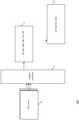
- FIG. 1 is a simplified block diagram of at least one embodiment of a battery powered system 100 with interleaved discharge of batteries, according to various embodiments.
- the system 100 includes switch circuitry 10 to selectively couple batteries 9 to a voltage input node of a voltage regulation circuit 14 to interleave discharge of the batteries 9 to provide a content circuit 16 with a first power that is different than a second power corresponding to one of the batteries 9.
- the battery powered system 100 is a hot-swap battery powered system.
- the switch circuit 10 may include a multiplexor (not shown) and a control circuitry (not shown) to control the multiplexor.
- a voltage input node of the voltage regulation circuit 14 may be switched across the batteries 9 in round-robin format, to take power from each battery of batteries 9 in turn.
- the voltage regulation circuity 14 may include a boost converter, a buck converter, a boost-buck converter, or the like, or combinations thereof (not shown).
- the content circuit 10 may be of an untethered virtual reality kit or other portable multimedia electronic device, and in some embodiments may include a CPU component and a graphics component.
- each battery of the batteries 9 may be of a different battery pack, e.g., a hot swappable battery pack, of battery packs.
- the switch circuitry 10 includes a discharge management component (not shown).
- the discharge management component determines whether to increase or decrease a duration of a series of power pulses extracted from a given battery of batteries 9 in accordance with the state of charge of each individual battery of batteries 9 and/or calculates on-time for a transistor of the voltage regulation circuit 14 in accordance with the state of charge of each individual battery of batteries 9, or the like, or combinations thereof.
- three fully charged batteries e.g., three fully charged batteries having a similar electronic characteristics (e.g. s same power) are installed in battery powered system 100.
- the discharge management component may control a multiplexor or other switching component of switch circuitry 10 to cause each battery of batteries 9 to be connected to a voltage input node of a voltage regulation circuit 14.
- Each battery may be selectively coupled to the voltage input node for the same time duration, and an on-time at a transistor of the voltage regulation circuit 14 may be equal for all the batteries.
- the discharge management component may cause each battery of batteries 9 to be drained with a series of pulses over the same duration.
- a user may remove a first battery of batteries 9 while the second and third batteries of batteries 9 remain installed.
- the subset of remaining batteries may have equal charges, and the discharge management component may cause each battery of the subset to be selectively coupled to the voltage input node of voltage regulation circuit 14 for the same time duration, and an on-time at a transistor of the voltage regulation circuit 14 may be equal for all the batteries of the subset.
- the discharge management component may cause each battery of the subset to be drained with a series of pulses over the same duration.
- a user may install a new fully charged battery, e.g., a battery of the same electrical characteristic as the third battery.
- the discharge management component may cause the batteries 9 including the new battery to be switched in turn, but may cause the new battery to be connected for a different amount of time than other batteries of batteries 9, which may cause the new battery to discharge at a different rate (e.g. a higher rate) than a rate of discharge of each other battery.
- the discharge management component determines a charge of each installed battery of batteries 9, and selects an amount of time for the new battery to be selectively coupled based on the determined state of charge of that battery.
- the discharge management component may select a time for connecting the new battery to cause all of the batteries to be exhausted all at once, or the discharge management component may select the time for connecting the new battery to cause a subset of the batteries to not be exhausted all at once.
- the system 100 includes a programmable battery policy management setting (not shown).
- the switch circuitry 10 may be configured to determine a connection time for the first battery, wherein the determination is based on, e.g., based only on or based at least in part on, the policy management setting.
- the battery management policies include a first battery management policy to exhaust the plurality of batteries 9 together and a second battery management policy of staggered exhaustion.
- the switch circuitry 10 may determine an equal connection time for fully charged batteries of the plurality of batteries 9 if the battery policy management setting corresponds to the first policy, and the switch circuitry 10 determines unequal connection times for fully charged batteries of the plurality of batteries 9 if the battery policy management setting corresponds to the second policy.
- the switch circuitry 10 may include a charge estimation component (not shown) to establish a battery state-of-charge of an individual one of the batteries 9, and the discharge management component may determine the charge of the new battery via communications with the charge estimation component.
- the discharge management component may determine a charge of the new battery using any known method for determining the charge of a battery and the switch circuitry 10 may or may not include a charge estimation component.
- At least one of the batteries 9 may have a different electrical characteristic than other batteries of the batteries 9.
- one of the batteries 9 may be a different size than another one of the batteries 9.
- the discharge management component may cause a larger battery to be connected for a different amount of time than each of the other batteries 9, which may cause the larger battery to discharge at a different rate (e.g., a higher rate) than a rate of discharge of each other battery.
- the discharge management component may cause a targeted one battery of the batteries 9 to discharge down to a predetermined threshold, e.g., 10% of charge, ahead of the other batteries, to allow a user to hot swap the targeted batteries before the other batteries of the batteries 9 reach the threshold charge.
- a predetermined threshold e.g. 10% of charge
- the switch circuitry 10 determines a first ratio of charge to time period that is different than a second ratio of charge to time period to cause staggered battery exhaustion.
- the switch circuitry 10 selects a first time period associated with the selective coupling of a corresponding battery to coincide with the first ratio and the second time period associated with selective coupling of a corresponding battery to coincide with the second ratio.
- FIG. 2 is a simplified block diagram of another embodiment of a battery powered system 200 including switch circuitry 30 having a charge estimation component (e.g. charge estimation module 25) and a discharge management component (e.g., discharge management module 23), according to various embodiments.
- the charge estimation module 25 may obtain an estimate of the state of charge of a battery (of batteries 29), which in embodiments, may be batteries having no in-battery gas gauge circuitry.
- the charge estimation module 25 may estimate the open-circuit voltage, and use this estimate as a proxy for the battery state of charge.
- the open-circuit voltage may be reduced while the battery is selectively coupled (e.g.
- FIG. 4 illustrates a graph depicting voltage and time for a battery during and after discharging. The time axis in FIG. 4 is for a single turn of discharging, while FIG. 5 illustrates another graph depicting voltage and time ranging from full charge to empty (multiple turns of discharging).
- a battery may take a first time to return to close to the true open-circuit voltage, and the first time may be greater than a second time of selectively coupling the other batteries of batteries 29 of the battery powered system 100.
- the first time may be several minutes, and the second time may be significantly less than the first time.
- the charge estimation module 25 may estimate a final value of the open-circuit voltage by using a voltage measurement taken at a time of selective coupling of one of the other batteries of the batteries 29 by taking into account the rate at which the voltage is recovering.
- the charge estimate module 25 may signal 27 (based on the estimate) the discharge management module 23, which may select an amount of time for the new battery to be selectively coupled based on the determined charged indicated by the signal 27.
- the charge estimation module 25 may sample a voltage recovery curve on each battery of the batteries 29.
- the charge estimation module may read (not shown) a voltage signal from the battery that just finished discharging (this may be referred to as the "relaxing battery").
- a time of sampling a given battery may correspond to a time the given battery is not selectively coupled to V in of voltage regulation circuit 24 (which is illustrated as a boost convertor for the purpose of explanation of one example and not to imply any limitation as to the configuration of the voltage regulation circuit 24).
- the switch circuitry 30 may determine whether to skip a turn of providing power for the given battery in order to measure an extended voltage recovery.
- the determination may be based on a quantity of the batteries 29, a ratio of the calculated on-time for the transistor Q1 of the voltage regulation circuit 24 to a total of the calculated on-times, a characteristic of the given battery, a user input indicating desired accuracy, or the like, or combinations thereof. In some cases, skipping turn(s) may provide significantly greater accuracy then performing the measurement without skipping any turns.
- the switch circuitry 30 may output a battery status report to the content circuitry 26 based on a result of the charge estimation.
- the charge estimation module 25 may analyze a ripple signal 28 associated with a ripple on output capacitor C1 of the voltage regulation circuit 24.
- the width of the switching pulses at transistor Q1 may be known.
- a battery at low state of charge will be operating at a lower voltage, and exhibit higher impedance. As a result, the battery will have a diminished ability to energize the inductor L of the voltage regulation circuit 24.
- a diminished energy level in inductor L1 may lead to a greater droop across capacitor C1 at a known current draw from V out .
- switch circuitry 30 may obtain state of charge information for a "dumb" battery of batteries 29, e.g. a non-smart battery, e.g., a battery without gas gauge circuitry, and provide that information to content circuitry 26 for output to a user and/or for determining a power state of a component of the content circuitry 26.
- Dumb batteries may be used for multi-pack systems including multipack untethered virtual reality kits with a managed discharge scheme. Hot-swapping may be facilitated, with system policies to manage power drawn from the subset of batteries remaining after removal of a battery.
- Batteries 29 with unequal states of charge can be combined to contribute their combined power to the content circuitry 26. Battery drain can be managed to sustain high power from a number of battery packs, while discharging them to become exhausted at about the same time, or managing one to discharge first, so that the others can still sustain high power while the discharged one is hot-swapped out.
- FIG. 3 is a simplified flow diagram of another method for interleaved discharge of batteries that may be executed by the system of FIG. 2 , according to various embodiments.
- the switch circuitry 30 may select the next battery to provide power.
- the next battery may be a next battery (N) in a sequence, e.g., a logical sequence of batteries.
- the switch circuitry 30 may set a battery status indicator to a first setting, e.g., "present”.
- the switch circuitry 30 may analyze a voltage signal, and report battery status of last-used battery.
- the last-used battery may be a previous battery (N-1) in the logical sequence, e.g., a battery most recently selectively coupled to the switch circuitry 30.
- a physical sequence of battery slots may include a number of batteries slots.
- the logical sequence of batteries to be each selectively coupled to the switch circuitry 30 in turn may include batteries corresponding to only a subset of the battery slots (for instance, including, but not limited to, if at least one battery is not installed). Also, it should be appreciated that an order of the logical sequence of batteries need not correspond to an order of the physical sequence of battery slots.
- the switch circuitry 30 may not set the battery status indicator to the first setting.
- the battery status flag may be set to a different second different setting, e.g., "absent".
- the method may include setting or unsetting a battery status indicator, such as a flag, for each of the batteries to indicate if the battery is present or not.
- the indicator may be set or reset based on analysis of the voltage signal in block 49 and/or determining whether a voltage is present on the corresponding battery in diamond 43.
- FIG. 6 is a simplified flow diagram of managing power provision in a multimedia electronic device that may be executed by any of the systems described herein, according to various embodiments.
- the system may selectively couple a first battery of the multimedia electronic device to a voltage input node of a voltage regulation circuit of the multimedia electronic device.
- the system may selectively couple a second battery of the multimedia electronic device to the voltage input node of the voltage regulation circuit of the multimedia electronic device.
- the system may interleave discharging of the first and second batteries to provide the multimedia electronic device coupled to an output node of the voltage regulation circuit with an aggregated power consumed from a group of batteries that includes the first battery and the second battery.
- the aggregated power may be different than, e.g., greater than, a power corresponding to one of the batteries.
- an untethered virtual reality kit may (at a given point in time) require power in the hundreds of watts, which may be aggregated by discharging in tandem by more than one 100 Wh battery.
- the system may select a first time period associated with the selective coupling of the first battery based on an estimated charge of the first battery.
- the system may select a second time period associated with the selectively coupling of the second battery based on an estimated charge of the second battery.
- the first time period may be different than the second time period.
- the estimated charge of the first battery is equal to the estimated charge of the second battery.
- the system determines whether to cause a staggered exhaustion of the first and second batteries. In response to determining to cause the staggered exhaustion, the system determines a first ratio of charge to time period that is different than a second ratio of charge to time period. The system selects the first time period to coincide with the first ratio and the second time period to coincide with the second ratio.
- a multimedia electronic device such as an untethered virtual reality kit including a vest for installation of three or more batteries, e.g., hot-swappable batteries, may be provided and a virtual reality headset powered by the vest, may be provided.
- the multimedia electronic device may include content circuitry to provide multimedia content, a voltage regulation circuit including a voltage output node to couple to the content circuitry, and a voltage input node, and switch circuity to selectively couple a plurality of batteries to the voltage input node to interleave discharge of the plurality of batteries to provide the content circuit with an aggregated power consumed from the plurality of batteries, the aggregated power greater than a power corresponding to one of the batteries.
- At least a first of the plurality of batteries is void of in-battery gas gauge circuitry
- the switch circuitry may include a charge estimation component to establish a battery state-of-charge of the first battery, the charge estimation component to sample a voltage recovery curve for the first battery or analyze a ripple on an output capacitor of the voltage regulation circuit, and ascertain a battery state for the first battery based on at least one of the sampled voltage recovery curve or the ripple analysis.
- the switch circuitry may determine a connection time for the first battery, wherein the determination is based on a result of the ascertainment, and switch a transistor of the voltage regulation circuit based on the determined connection time.
- the switch circuitry may access a programmable battery policy management setting, and determine the connection time based on a value of the programmable battery policy management setting and a result of the ascertainment.
- the switch circuitry identifies one of a plurality of battery management policies that includes at least a first battery management policy to exhaust the plurality of batteries together and a second battery management policy of staggered exhaustion, determines an equal connection time for fully charged batteries of the plurality of batteries in response to identification of the first battery management policy, and determines unequal connection times for fully charged batteries of the plurality of batteries in response to identification the second battery management policy.
- At least a first of the plurality of batteries is void of in-battery gas gauge circuitry
- the switch circuitry may include a charge estimation component to establish a battery state-of-charge of the first battery, the charge estimation component to, at a time that the first battery is selectively coupled to the voltage input node of the voltage regulation circuit, estimate an open-circuit voltage of a selectively non-coupled second battery of the plurality of batteries, and determine a battery state for the non-coupled second battery based on the open-circuit voltage estimate.
- the charge estimation component may measure a voltage corresponding to the selectively non-coupled second battery, and may estimate the open-circuit voltage with the measured voltage and a voltage recovery rate.
- the switch circuitry may sample a voltage recovery curve for each of the batteries, and determine the voltage recovery rate for the selectively non-coupled second battery with a respective one of the voltage recovery curve samples.
- the switch circuitry may power the content circuitry with only a subset of the plurality of batteries for a time period, and during the time period, sample the voltage recovery curve for one of the batteries that is not of the subset.
- a computer-readable medium having stored thereon instructions may be provided.
- the instructions may cause the multimedia electronic device to perform operations for implementing a battery management policy on a hot-swap battery powered system of the multimedia electronic device having a plurality of batteries without gas gauge.
- the operations may be operable to cause a voltage recovery curve of a first of the batteries of the multimedia electronic device to be sampled or analyze a ripple corresponding to an output capacitor of a voltage regulation circuit selectively coupled to the first battery, the voltage regulation circuit of the multimedia electronic device, and to ascertain a battery state of the first battery based on at least one of the sampled voltage recovery curve or the ripple analysis.
- the operations may be operable to determine a connection time for the first battery to power the multimedia electronic device, wherein the determination is based on a result of the ascertainment, and switch a transistor of the voltage regulation circuit based on the determined connection time.
- the operations may be operable to access a programmable battery policy management setting, determine the connection time based on a value of the programmable battery policy management setting and a result of the ascertainment.
- the operations may be operable to, at a time that the first battery is selectively coupled to a voltage input node of the voltage regulation circuit, estimate an open-circuit voltage of selectively non-coupled second battery of the plurality of batteries, and determine a battery state based on the open-circuit voltage estimate.
- the operations may be operable to measure a voltage corresponding to the selectively non-coupled second battery, and estimate the open-circuit voltage using the measured voltage and a voltage recovery rate.
- FIG. 7 illustrates an example computing device that may employ the apparatuses and/or methods described herein, according to various embodiments.
- computing device 1500 may include a number of components, such as battery interface 1536 (e.g., a battery housing, a battery connector, or the like, or combinations thereof) for removably receiving a plurality of batteries (e.g., a plurality of battery packs).
- the battery interface 1536 may be coupled to circuitry (not shown), which may include any of the switch circuitry described anywhere herein, or a circuitry to implement a component/module thereof.
- the circuitry may also include a voltage regulation circuit, such as a boost converter, a buck converter, a boost-buck convertor, or the like.
- the circuitry may selectively couple a plurality of batteries removably received at battery interface 1536 to a voltage input node of the voltage regulation circuit to interleave discharge of the plurality of batteries to provide content circuitry (not shown) of the circuity with an aggregated power consumed from the plurality of batteries.
- the aggregated power is different than, e.g., greater than, a power corresponding to one of the batteries.
- circuitry of the computing device may include content circuitry and selection circuitry, which may include one or more processor(s) 1504 and the at least one communication chip 1506, which may be physically and electrically coupled to the one or more processor(s) 1504.
- the communication chip 1506 may be part of the one or more processor(s) 1504.
- computing device 100 may include printed circuit board (PCB) 1502.
- PCB printed circuit board
- the one or more processor(s) 1504 and communication chip 1506 may be disposed thereon.
- the various components may be coupled without the employment of PCB 1502.
- computing device 1500 may include other components that may or may not be physically and electrically coupled to the PCB 1502. These other components include, but are not limited to, a memory controller (not shown), volatile memory (e.g., dynamic random access memory (DRAM) 1520), nonvolatile memory such as read only memory (ROM) 1524, flash memory 1522, an I/O controller (not shown), a digital signal processor (not shown), a crypto processor (not shown), a graphics processor 1530, one or more antenna 1528, a display (not shown), a touch screen display 1532, a touch screen controller 546, an audio codec (not shown), a video codec (not shown), a global positioning system (GPS) device 1540, a compass 1542, an accelerometer (not shown), a gyroscope (not shown), a speaker 1550, a camera 1552, and a mass storage device (such as hard disk drive, a solid state drive, compact disk (CD), digital versatile disk (DVD)) (not
- DRAM dynamic
- the one or more processor(s) 1504, flash memory 1522, and/or a storage device may include associated firmware (not shown) storing programming instructions configured to enable computing device 1500, in response to execution of the programming instructions by one or more processor(s) 1504, to practice all or selected aspects of the methods described herein.
- the programming instructions may implement the earlier described modules with references to the respective figures of Figures 1-3 .
- these aspects may additionally or alternatively be implemented using hardware separate from the one or more processor(s) 1504, flash memory 1512, or storage device 1511.
- the communication chips 1506 may enable wired and/or wireless communications for the transfer of data to and from the computing device 1500.
- wireless and its derivatives may be used to describe circuits, devices, systems, methods, techniques, communications channels, etc., that may communicate data through the use of modulated electromagnetic radiation through a non-solid medium. The term does not imply that the associated devices do not contain any wires, although in some embodiments they might not.
- the communication chip 506 may implement any of a number of wireless standards or protocols, including but not limited to IEEE 702.20, Long Term Evolution (LTE), LTE Advanced (LTE-A), General Packet Radio Service (GPRS), Evolution Data Optimized (Ev-DO), Evolved High Speed Packet Access (HSPA+), Evolved High Speed Downlink Packet Access (HSDPA+), Evolved High Speed Uplink Packet Access (HSUPA+), Global System for Mobile Communications (GSM), Enhanced Data rates for GSM Evolution (EDGE), Code Division Multiple Access (CDMA), Time Division Multiple Access (TDMA), Digital Enhanced Cordless Telecommunications (DECT), Worldwide Interoperability for Microwave Access (WiMAX), Bluetooth, derivatives thereof, as well as any other wireless protocols that are designated as 3G, 5G, 5G, and beyond.
- IEEE 702.20 Long Term Evolution (LTE), LTE Advanced (LTE-A), General Packet Radio Service (GPRS), Evolution Data Optimized (Ev-DO),
- the computing device 1500 may include a plurality of communication chips 1506.
- a first communication chip 1506 may be dedicated to shorter range wireless communications such as Wi-Fi and Bluetooth
- a second communication chip 506 may be dedicated to longer range wireless communications such as GPS, EDGE, GPRS, CDMA, WiMAX, LTE, Ev-DO, and others (e.g., developed or yet to be developed).
- the computing device 1500 may be an untethered virtual reality kit, a laptop, a netbook, a notebook, an ultrabook, a smartphone, a computing tablet, a personal digital assistant (PDA), an ultra-mobile PC, a mobile phone, a desktop computer, a server, a printer, a scanner, a monitor, a set-top box, an entertainment control unit (e.g., a gaming console or automotive entertainment unit), a digital camera, an appliance, a portable music player, a digital video recorder, or the like, or combinations thereof.
- the computing device 1500 may be any other electronic device that processes data.
- the computer-usable or computer-readable medium may be, for example but not limited to, an electronic, magnetic, optical, electromagnetic, infrared, or semiconductor system, apparatus, device, or propagation medium. More specific examples (a non- exhaustive list) of the computer-readable medium would include the following: an electrical connection having one or more wires, a portable computer diskette, a hard disk, a random access memory (RAM), a read-only memory (ROM), an erasable programmable read-only memory (EPROM or Flash memory), an optical fiber, a portable compact disc read-only memory (CD-ROM), an optical storage device, a transmission media such as those supporting the Internet or an intranet, or a magnetic storage device.
- the computer- usable or computer-readable medium could even be paper or another suitable medium upon which the program is printed, as the program can be electronically captured, via, for instance, optical scanning of the paper or other medium, then compiled, interpreted, or otherwise processed in a suitable manner, if necessary, and then stored in a computer memory.
- a computer-usable or computer-readable medium may be any medium that can contain, store, communicate, propagate, or transport the program for use by or in connection with the instruction execution system, apparatus, or device.
- the computer- usable medium may include a propagated data signal with the computer-usable program code embodied therewith, either in baseband or as part of a carrier wave.
- the computer usable program code may be transmitted using any appropriate medium, including but not limited to wireless, wireline, optical fiber cable, RF, etc.
- Computer program code for carrying out operations of the present disclosure may be written in any combination of one or more programming languages, including an object oriented programming language such as Java, Smalltalk, C++ or the like and conventional procedural programming languages, such as the "C" programming language or similar programming languages.
- the program code may execute entirely on the user's computer, partly on the user's computer, as a stand-alone software package, partly on the user's computer and partly on a remote computer or entirely on the remote computer or server.
- the remote computer may be connected to the user's computer through any type of network, including a local area network (LAN) or a wide area network (WAN), or the connection may be made to an external computer (for example, through the Internet using an Internet Service Provider).
- LAN local area network
- WAN wide area network
- Internet Service Provider for example, AT&T, MCI, Sprint, EarthLink, MSN, GTE, etc.
Landscapes
- Engineering & Computer Science (AREA)
- Power Engineering (AREA)
- Manufacturing & Machinery (AREA)
- Chemical & Material Sciences (AREA)
- Chemical Kinetics & Catalysis (AREA)
- Electrochemistry (AREA)
- General Chemical & Material Sciences (AREA)
- Secondary Cells (AREA)
- Charge And Discharge Circuits For Batteries Or The Like (AREA)
Claims (6)
- Verfahren zum Verwalten der Stromversorgung in einer elektronischen Multimedia-Vorrichtung, wobei das Verfahren umfasst:selektives Koppeln (71) einer ersten Batterie der elektronischen Multimedia-Vorrichtung mit einem Spannungseingangsknoten (Vin) einer Spannungsregelschaltung (14; 24) der elektronischen Multimedia-Vorrichtung;selektives Koppeln (73) einer zweiten Batterie der elektronischen Multimedia-Vorrichtung mit dem Spannungseingangsknoten der Spannungsregelschaltung (14; 24) der elektronischen Multimedia-Vorrichtung; undVerschachteln des Entladens (75) der ersten und der zweiten Batterie, um der elektronischen Multimedia-Vorrichtung, die mit einem Ausgangsknoten (Vout) der Spannungsregelungsschaltung (14; 24) gekoppelt ist, einen aggregierten Strom bereitzustellen, der von einer Gruppe von Batterien (9; 29) verbraucht wird, die die erste Batterie und die zweite Batterie beinhaltet, wobei der aggregierte Strom höher ist als ein Strom, der einer der Gruppe von Batterien (9; 29) entspricht, Auswählen einer ersten Verbindungszeit, die dem selektiven Koppeln der ersten Batterie zugeordnet ist, basierend auf einer geschätzten Ladung der ersten Batterie;Auswahl einer zweiten Verbindungszeit, die dem selektiven Koppeln der zweiten Batterie zugeordnet ist, basierend auf einer geschätzten Ladung der zweiten Batterie;gekennzeichnet durchBestimmen, ob ein gestaffeltes Entleeren der ersten und der zweiten Batterie durch Identifizieren einer von mehreren Batterieverwaltungsrichtlinien verursacht werden soll, die mindestens eine erste Batterieverwaltungsrichtlinie, um die Gruppe von Batterien (9; 29) gemeinsamen zu entleeren und eine zweite Batterieverwaltungsrichtlinie zum gestaffelten Entleeren beinhaltet;als Reaktion auf das Bestimmen, das gestaffelte Entleeren zu verursachen, Bestimmen eines ersten Verhältnisses von Ladung zu Verbindungszeit, das sich von einem zweiten Verhältnis von Ladung zu Verbindungszeit unterscheidet; undAuswählen der ersten Verbindungszeit, damit sie mit dem ersten Verhältnis übereinstimmt, und der zweiten Verbindungszeit, damit sie mit dem zweiten Verhältnis übereinstimmt.
- Computerlesbares Medium, das Befehle umfasst, die eine Rechenvorrichtung als Reaktion auf das Ausführen der Befehle durch einen Prozessor der Rechenvorrichtung veranlassen, das Bereitstellen von Strom in einer elektronischen Multimedia-Vorrichtung zu verwalten, um das Verfahren nach Anspruch 1 durchzuführen.
- Vorrichtung zum Betreiben eines Hot-Swapbatteriebetriebenen Systems zum Bereitstellen von Strom für eine elektronische Multimedia-Vorrichtung, umfassend:Mittel zum selektiven Koppeln einer ersten Batterie und einer zweiten Batterie mit einem Spannungseingangsknoten (Vin) einer Spannungsregelschaltung (14; 24);Mittel zum Verschachteln des Entladens der ersten und der zweiten Batterie, um der elektronischen Multimedia-Vorrichtung, die mit einem Ausgangsknoten (Vout) der Spannungsregelungsschaltung (14; 24) gekoppelt ist, einen aggregierten Strom bereitzustellen, der von einer Gruppe von Batterien (9; 29) verbraucht wird, die die erste Batterie und die zweite Batterie beinhaltet, wobei der aggregierte Strom höher ist als ein Strom, der einer der Gruppe von Batterien (9; 29) entspricht;ferner umfassend:Mittel zur Auswahl einer ersten Verbindungszeit, die dem selektiven Koppeln der ersten Batterie zugeordnet ist, basierend auf einer geschätzten Ladung der ersten Batterie;Mittel zur Auswahl einer zweiten Verbindungszeit, die dem selektiven Koppel der zweiten Batterie zugeordnet ist, basierend auf einer geschätzten Ladung der zweiten Batterie;wobei sich die erste Verbindungszeit von der zweiten Zeitperiode unterscheidet;gekennzeichnet durchMittel zum Bestimmen, ob ein gestaffeltes Entleeren der ersten und der zweiten Batterie durch Identifizieren einer von mehreren Batterieverwaltungsrichtlinien verursacht werden soll, die mindestens eine erste Batterieverwaltungsrichtlinie, um die Gruppe von Batterien (9; 29) gemeinsamen zu entleeren eine zweite Batterieverwaltungsrichtlinie zum gestaffelten Entleeren beinhaltet;als Reaktion auf das Bestimmen, das gestaffelte Entleeren zu verursachen, das Mittel zum Bestimmen, ob ein gestaffeltes Entleeren der ersten und zweiten Batterien verursacht werden soll, dazu ausgelegt ist, ein erstes Verhältnis von Ladung zu Verbindungszeit zu bestimmen, das sich von einem zweiten Verhältnis von Ladung zu Verbindungszeit unterscheidet; unddie erste Verbindungszeit auszuwählen, damit sie mit dem ersten Verhältnis übereinstimmt, und die zweite Verbindungszeit, damit sie mit dem zweiten Verhältnis übereinstimmt.
- Elektronische Multimedia-Vorrichtung, umfassend:eine Inhaltsschaltungsanordnung (16; 26) zum Bereitstellen von Multimedia-Inhalten;eine Spannungsregelungsschaltung (14; 24), die einen Spannungsausgangsknoten (Vout) zum Koppeln mit der Inhalts-Schaltungsanordnung (16; 26) und einen Spannungseingangsknoten (Vin) beinhaltet; undeine Schaltung (10; 30) zum selektiven Koppeln einer ersten Batterie und einer zweiten Batterie mit dem Spannungseingangsknoten (Vin), um die Entladung der ersten und der zweiten Batterie zu verschachteln, um der Inhaltsschaltung (16) einen aggregierten Strom bereitzustellen, der von einer Gruppe von Batterien (9; 29) verbraucht wird, die die erste Batterie und die zweite Batterie beinhaltet, wobei der aggregierte Strom höher als ein Strom ist, der einer der Gruppe von Batterien (9; 29) entspricht,zumindest die erste Batterie keine batterieinterne Gasmessschaltungsanordnung aufweist, und wobei die Schalt-Schaltungsanordnung (10) eine Ladungsschätzkomponente (25) beinhaltet, um einen Batterieladezustand der ersten Batterie zu erstellen, wobei die Ladungsschätzkomponente (25) dazu dient:eine Spannungswiederherstellungskurve für die erste Batterie abzutasten oder eine Welligkeit an einem Ausgangskondensator der Spannungsregelungsschaltung zu analysieren; undeinen Batteriezustand für die erste Batterie basierend auf mindestens einer der abgetasteten Spannungswiederherstellungskurve oder der Welligkeitsanalyse zu ermitteln,die Schalt-Schaltungsanordnung (10; 30) dazu dient:eine Verbindungszeit für die erste Batterie zu bestimmen, wobei das Bestimmen auf einem Ergebnis der Ermittlung basiert;einen Transistor der Spannungsregelungsschaltung basierend auf der bestimmten Verbindungszeit zu schalten; dadurch gekennzeichnet, dass die Schalt-Schaltungsanordnung (10; 30) ferner dazu ausgelegt ist:eine von mehreren Batterieverwaltungsrichtlinien zu identifizieren, die mindestens eine erste Batterieverwaltungsrichtlinie, um die Gruppe von Batterien (9; 29) gemeinsam zu entleeren und eine weite Batterieverwaltungsrichtlinie zum gestaffelten Entleeren beinhaltet; undals Reaktion auf das Identifizieren der ersten Batterieverwaltungsrichtlinie, Bestimmen einer gleichen Verbindungszeit für voll geladene Batterien der Gruppe von Batterien (9; 29); undals Reaktion auf das Identifizieren der zweiten Batterieverwaltungsrichtlinie, Bestimmen ungleicher Verbindungszeiten für voll geladene Batterien der Gruppe von Batterien (9; 29).
- Elektronische Multimedia-Vorrichtung nach Anspruch 4, wobei die Schalt-Schaltungsanordnung (10; 30) dazu ausgelegt ist:auf eine programmierbare Batterierichtlinien-Verwaltungseinstellung zuzugreifen; unddie Verbindungszeit basierend auf einem Wert der programmierbaren Batterierichtlinien-Verwaltungseinstellung und einem Ergebnis der Ermittlung zu bestimmen.
- Elektronische Multimedia-Vorrichtung nach einem der Ansprüche 4 bis 5, die ferner die Schalt-Schaltungsanordnung (10; 30) umfasst, um den Spannungseingangsknoten über die Gruppe von Batterien (9; 29) im Umlaufverfahren zu schalten.
Applications Claiming Priority (2)
| Application Number | Priority Date | Filing Date | Title |
|---|---|---|---|
| US15/074,783 US11159029B2 (en) | 2016-03-18 | 2016-03-18 | Battery powered system with interleaved discharge of batteries |
| PCT/US2017/017404 WO2017160432A1 (en) | 2016-03-18 | 2017-02-10 | Battery powered system with interleaved discharge of batteries |
Publications (3)
| Publication Number | Publication Date |
|---|---|
| EP3430494A1 EP3430494A1 (de) | 2019-01-23 |
| EP3430494A4 EP3430494A4 (de) | 2019-09-04 |
| EP3430494B1 true EP3430494B1 (de) | 2021-06-23 |
Family
ID=59851812
Family Applications (1)
| Application Number | Title | Priority Date | Filing Date |
|---|---|---|---|
| EP17767123.7A Active EP3430494B1 (de) | 2016-03-18 | 2017-02-10 | Batteriebetriebenes system mit verschachtelter entladung von batterien |
Country Status (4)
| Country | Link |
|---|---|
| US (1) | US11159029B2 (de) |
| EP (1) | EP3430494B1 (de) |
| CN (1) | CN108700920A (de) |
| WO (1) | WO2017160432A1 (de) |
Families Citing this family (6)
| Publication number | Priority date | Publication date | Assignee | Title |
|---|---|---|---|---|
| NL2017395B1 (en) * | 2016-08-30 | 2018-03-08 | Dcpower Holding B V | A replaceable smart battery pack, a battery pack holder and a mobile power supply system |
| US10658841B2 (en) * | 2017-07-14 | 2020-05-19 | Engie Storage Services Na Llc | Clustered power generator architecture |
| US11152663B2 (en) * | 2018-06-18 | 2021-10-19 | Datalogic Ip Tech S.R.L. | Advanced battery system |
| US11881735B2 (en) | 2018-07-11 | 2024-01-23 | Cummins Inc. | Integration of second-use of Li-ion batteries in power generation |
| CN115715449A (zh) * | 2020-06-25 | 2023-02-24 | 米沃奇电动工具公司 | 用于多舱电力供应装置的充电平衡 |
| US12518731B2 (en) * | 2023-03-17 | 2026-01-06 | Bose Corporation | Power-adaptive active noise reduction (ANR) headset |
Family Cites Families (17)
| Publication number | Priority date | Publication date | Assignee | Title |
|---|---|---|---|---|
| US5808445A (en) | 1995-12-06 | 1998-09-15 | The University Of Virginia Patent Foundation | Method for monitoring remaining battery capacity |
| JP3323832B2 (ja) * | 1999-06-08 | 2002-09-09 | インターナショナル・ビジネス・マシーンズ・コーポレーション | 複数の電池の充放電を制御する方法 |
| JP3398703B2 (ja) | 2000-02-14 | 2003-04-21 | 米沢日本電気株式会社 | 放電回路及びデューティー比設定方法 |
| US7003679B1 (en) | 2001-10-12 | 2006-02-21 | Xilinx, Inc. | System and method for storing a charging algorithm and charging methodology associated with a battery and selectively connecting a critical circuit to a battery voltage pin |
| US6803746B2 (en) * | 2001-11-02 | 2004-10-12 | Aker Wade Power Technologies, Llc | Fast charger for high capacity batteries |
| US20050083018A1 (en) | 2003-10-20 | 2005-04-21 | Morrow James S. | Battery charge regulator |
| US8860377B2 (en) * | 2006-02-09 | 2014-10-14 | Karl F. Scheucher | Scalable intelligent power supply system and method |
| DE102008040524B4 (de) | 2008-07-18 | 2022-10-20 | Robert Bosch Gmbh | Elektrowerkzeug mit einer Vorrichtung zur pulsweitenmodulierten Stromregelung |
| WO2011005152A1 (en) | 2009-07-10 | 2011-01-13 | St. Jude Medical Ab | Battery discharge measurement device and method |
| US9197081B2 (en) * | 2009-08-28 | 2015-11-24 | The Charles Stark Draper Laboratory, Inc. | High-efficiency battery equalization for charging and discharging |
| KR101294025B1 (ko) | 2011-08-02 | 2013-08-08 | 숭실대학교산학협력단 | 휴대 기기, 배터리 팩, 배터리부 제어 장치 및 방법 |
| US10291051B2 (en) * | 2013-01-11 | 2019-05-14 | Zpower, Llc | Methods and systems for recharging a battery |
| US9214826B2 (en) | 2013-02-06 | 2015-12-15 | Clint L. Skipper | Alternating battery power supply system with inter-battery charging and rate of discharge management |
| US9438054B2 (en) * | 2013-05-01 | 2016-09-06 | Apple Inc. | Battery charger integrated circuit chip |
| WO2015068537A1 (ja) | 2013-11-05 | 2015-05-14 | 日本電気株式会社 | 電源装置、電力供給方法、制御装置、及びプログラム |
| CN104701911A (zh) * | 2013-12-09 | 2015-06-10 | 上海机电工程研究所 | 一种锂芯电池 |
| US10591979B2 (en) * | 2015-04-03 | 2020-03-17 | Microsoft Technology Licensing, Llc | Battery management in a device with multiple batteries |
-
2016
- 2016-03-18 US US15/074,783 patent/US11159029B2/en active Active
-
2017
- 2017-02-10 WO PCT/US2017/017404 patent/WO2017160432A1/en not_active Ceased
- 2017-02-10 EP EP17767123.7A patent/EP3430494B1/de active Active
- 2017-02-10 CN CN201780012214.2A patent/CN108700920A/zh active Pending
Also Published As
| Publication number | Publication date |
|---|---|
| US20170271891A1 (en) | 2017-09-21 |
| CN108700920A (zh) | 2018-10-23 |
| US11159029B2 (en) | 2021-10-26 |
| EP3430494A4 (de) | 2019-09-04 |
| WO2017160432A1 (en) | 2017-09-21 |
| EP3430494A1 (de) | 2019-01-23 |
Similar Documents
| Publication | Publication Date | Title |
|---|---|---|
| US11159029B2 (en) | Battery powered system with interleaved discharge of batteries | |
| EP4145669A1 (de) | Lade-/entladeschaltung und elektronische vorrichtung | |
| EP2365350B1 (de) | Vorrichtung und verfahren zum synchronen messen von strom und spannung der sekundärbatterie | |
| US9753094B2 (en) | Battery performance under high temperature exposure | |
| US10389147B2 (en) | Method for charging battery and electronic device thereof | |
| US9817076B2 (en) | Estimation circuit for SOC and SOH of battery | |
| WO2016099744A1 (en) | Mechanism for extending cycle life of a battery | |
| US20150198932A1 (en) | Power supply, electronic device including the same, and power supply method thereof | |
| CN109256825B (zh) | 充电方法及电子装置 | |
| US20160294286A1 (en) | Power consumption reduced type power converter | |
| CN103633387A (zh) | 电子装置系统和电池组 | |
| US10284199B2 (en) | Voltage tolerant termination presence detection | |
| CN111830394A (zh) | 充电电路故障检测方法、电子设备及计算机可读存储介质 | |
| CN106067889B (zh) | 电子装置及其上传方法 | |
| US8438412B1 (en) | System, method, and computer program for enabling an amount of multitasking for use by an operating system | |
| US20160006286A1 (en) | Method and system of charging a battery | |
| KR20150122416A (ko) | 안전 플러그의 상태를 검출하는 방법 및 장치 | |
| CN1321479C (zh) | 二次电池充电方法和装置 | |
| CN111157907B (zh) | 检测方法及装置、充电方法及装置、电子设备、存储介质 | |
| CN100380776C (zh) | 具有附件的电子设备及其电池间的切换 | |
| WO2019060665A1 (en) | SYSTEM FOR CHARGING CELLS ASSEMBLED IN A BATTERY | |
| WO2024046161A1 (zh) | 一种电池预处理控制方法、装置及车辆 | |
| CN118339700A (zh) | 电芯均衡方法、装置、电子设备和存储介质 | |
| CN107895983A (zh) | 电池均衡方法与装置、计算机可读存储介质、电池管理装置与运载工具 | |
| EP3502723A1 (de) | Programm, system und verfahren zur bestimmung eines phasenverlust |
Legal Events
| Date | Code | Title | Description |
|---|---|---|---|
| STAA | Information on the status of an ep patent application or granted ep patent |
Free format text: STATUS: THE INTERNATIONAL PUBLICATION HAS BEEN MADE |
|
| PUAI | Public reference made under article 153(3) epc to a published international application that has entered the european phase |
Free format text: ORIGINAL CODE: 0009012 |
|
| STAA | Information on the status of an ep patent application or granted ep patent |
Free format text: STATUS: REQUEST FOR EXAMINATION WAS MADE |
|
| 17P | Request for examination filed |
Effective date: 20180815 |
|
| AK | Designated contracting states |
Kind code of ref document: A1 Designated state(s): AL AT BE BG CH CY CZ DE DK EE ES FI FR GB GR HR HU IE IS IT LI LT LU LV MC MK MT NL NO PL PT RO RS SE SI SK SM TR |
|
| AX | Request for extension of the european patent |
Extension state: BA ME |
|
| DAV | Request for validation of the european patent (deleted) | ||
| DAX | Request for extension of the european patent (deleted) | ||
| REG | Reference to a national code |
Ref country code: DE Ref legal event code: R079 Ref document number: 602017040840 Country of ref document: DE Free format text: PREVIOUS MAIN CLASS: G06F0001260000 Ipc: H02J0007000000 |
|
| A4 | Supplementary search report drawn up and despatched |
Effective date: 20190807 |
|
| RIC1 | Information provided on ipc code assigned before grant |
Ipc: H01M 10/44 20060101ALI20190801BHEP Ipc: H02J 7/00 20060101AFI20190801BHEP |
|
| RIN1 | Information on inventor provided before grant (corrected) |
Inventor name: KEATES, ANDREW |
|
| STAA | Information on the status of an ep patent application or granted ep patent |
Free format text: STATUS: EXAMINATION IS IN PROGRESS |
|
| 17Q | First examination report despatched |
Effective date: 20200408 |
|
| GRAP | Despatch of communication of intention to grant a patent |
Free format text: ORIGINAL CODE: EPIDOSNIGR1 |
|
| STAA | Information on the status of an ep patent application or granted ep patent |
Free format text: STATUS: GRANT OF PATENT IS INTENDED |
|
| INTG | Intention to grant announced |
Effective date: 20210114 |
|
| GRAS | Grant fee paid |
Free format text: ORIGINAL CODE: EPIDOSNIGR3 |
|
| GRAA | (expected) grant |
Free format text: ORIGINAL CODE: 0009210 |
|
| STAA | Information on the status of an ep patent application or granted ep patent |
Free format text: STATUS: THE PATENT HAS BEEN GRANTED |
|
| AK | Designated contracting states |
Kind code of ref document: B1 Designated state(s): AL AT BE BG CH CY CZ DE DK EE ES FI FR GB GR HR HU IE IS IT LI LT LU LV MC MK MT NL NO PL PT RO RS SE SI SK SM TR |
|
| REG | Reference to a national code |
Ref country code: GB Ref legal event code: FG4D |
|
| REG | Reference to a national code |
Ref country code: CH Ref legal event code: EP |
|
| REG | Reference to a national code |
Ref country code: DE Ref legal event code: R096 Ref document number: 602017040840 Country of ref document: DE Ref country code: AT Ref legal event code: REF Ref document number: 1405153 Country of ref document: AT Kind code of ref document: T Effective date: 20210715 |
|
| REG | Reference to a national code |
Ref country code: IE Ref legal event code: FG4D |
|
| REG | Reference to a national code |
Ref country code: NL Ref legal event code: FP |
|
| REG | Reference to a national code |
Ref country code: LT Ref legal event code: MG9D |
|
| PG25 | Lapsed in a contracting state [announced via postgrant information from national office to epo] |
Ref country code: BG Free format text: LAPSE BECAUSE OF FAILURE TO SUBMIT A TRANSLATION OF THE DESCRIPTION OR TO PAY THE FEE WITHIN THE PRESCRIBED TIME-LIMIT Effective date: 20210923 Ref country code: HR Free format text: LAPSE BECAUSE OF FAILURE TO SUBMIT A TRANSLATION OF THE DESCRIPTION OR TO PAY THE FEE WITHIN THE PRESCRIBED TIME-LIMIT Effective date: 20210623 Ref country code: FI Free format text: LAPSE BECAUSE OF FAILURE TO SUBMIT A TRANSLATION OF THE DESCRIPTION OR TO PAY THE FEE WITHIN THE PRESCRIBED TIME-LIMIT Effective date: 20210623 Ref country code: LT Free format text: LAPSE BECAUSE OF FAILURE TO SUBMIT A TRANSLATION OF THE DESCRIPTION OR TO PAY THE FEE WITHIN THE PRESCRIBED TIME-LIMIT Effective date: 20210623 |
|
| REG | Reference to a national code |
Ref country code: AT Ref legal event code: MK05 Ref document number: 1405153 Country of ref document: AT Kind code of ref document: T Effective date: 20210623 |
|
| PG25 | Lapsed in a contracting state [announced via postgrant information from national office to epo] |
Ref country code: NO Free format text: LAPSE BECAUSE OF FAILURE TO SUBMIT A TRANSLATION OF THE DESCRIPTION OR TO PAY THE FEE WITHIN THE PRESCRIBED TIME-LIMIT Effective date: 20210923 Ref country code: LV Free format text: LAPSE BECAUSE OF FAILURE TO SUBMIT A TRANSLATION OF THE DESCRIPTION OR TO PAY THE FEE WITHIN THE PRESCRIBED TIME-LIMIT Effective date: 20210623 Ref country code: SE Free format text: LAPSE BECAUSE OF FAILURE TO SUBMIT A TRANSLATION OF THE DESCRIPTION OR TO PAY THE FEE WITHIN THE PRESCRIBED TIME-LIMIT Effective date: 20210623 Ref country code: RS Free format text: LAPSE BECAUSE OF FAILURE TO SUBMIT A TRANSLATION OF THE DESCRIPTION OR TO PAY THE FEE WITHIN THE PRESCRIBED TIME-LIMIT Effective date: 20210623 Ref country code: GR Free format text: LAPSE BECAUSE OF FAILURE TO SUBMIT A TRANSLATION OF THE DESCRIPTION OR TO PAY THE FEE WITHIN THE PRESCRIBED TIME-LIMIT Effective date: 20210924 |
|
| PG25 | Lapsed in a contracting state [announced via postgrant information from national office to epo] |
Ref country code: SK Free format text: LAPSE BECAUSE OF FAILURE TO SUBMIT A TRANSLATION OF THE DESCRIPTION OR TO PAY THE FEE WITHIN THE PRESCRIBED TIME-LIMIT Effective date: 20210623 Ref country code: SM Free format text: LAPSE BECAUSE OF FAILURE TO SUBMIT A TRANSLATION OF THE DESCRIPTION OR TO PAY THE FEE WITHIN THE PRESCRIBED TIME-LIMIT Effective date: 20210623 Ref country code: AT Free format text: LAPSE BECAUSE OF FAILURE TO SUBMIT A TRANSLATION OF THE DESCRIPTION OR TO PAY THE FEE WITHIN THE PRESCRIBED TIME-LIMIT Effective date: 20210623 Ref country code: CZ Free format text: LAPSE BECAUSE OF FAILURE TO SUBMIT A TRANSLATION OF THE DESCRIPTION OR TO PAY THE FEE WITHIN THE PRESCRIBED TIME-LIMIT Effective date: 20210623 Ref country code: EE Free format text: LAPSE BECAUSE OF FAILURE TO SUBMIT A TRANSLATION OF THE DESCRIPTION OR TO PAY THE FEE WITHIN THE PRESCRIBED TIME-LIMIT Effective date: 20210623 Ref country code: ES Free format text: LAPSE BECAUSE OF FAILURE TO SUBMIT A TRANSLATION OF THE DESCRIPTION OR TO PAY THE FEE WITHIN THE PRESCRIBED TIME-LIMIT Effective date: 20210623 Ref country code: RO Free format text: LAPSE BECAUSE OF FAILURE TO SUBMIT A TRANSLATION OF THE DESCRIPTION OR TO PAY THE FEE WITHIN THE PRESCRIBED TIME-LIMIT Effective date: 20210623 Ref country code: PT Free format text: LAPSE BECAUSE OF FAILURE TO SUBMIT A TRANSLATION OF THE DESCRIPTION OR TO PAY THE FEE WITHIN THE PRESCRIBED TIME-LIMIT Effective date: 20211025 |
|
| PG25 | Lapsed in a contracting state [announced via postgrant information from national office to epo] |
Ref country code: PL Free format text: LAPSE BECAUSE OF FAILURE TO SUBMIT A TRANSLATION OF THE DESCRIPTION OR TO PAY THE FEE WITHIN THE PRESCRIBED TIME-LIMIT Effective date: 20210623 |
|
| REG | Reference to a national code |
Ref country code: DE Ref legal event code: R097 Ref document number: 602017040840 Country of ref document: DE |
|
| PG25 | Lapsed in a contracting state [announced via postgrant information from national office to epo] |
Ref country code: DK Free format text: LAPSE BECAUSE OF FAILURE TO SUBMIT A TRANSLATION OF THE DESCRIPTION OR TO PAY THE FEE WITHIN THE PRESCRIBED TIME-LIMIT Effective date: 20210623 |
|
| PLBE | No opposition filed within time limit |
Free format text: ORIGINAL CODE: 0009261 |
|
| STAA | Information on the status of an ep patent application or granted ep patent |
Free format text: STATUS: NO OPPOSITION FILED WITHIN TIME LIMIT |
|
| 26N | No opposition filed |
Effective date: 20220324 |
|
| PG25 | Lapsed in a contracting state [announced via postgrant information from national office to epo] |
Ref country code: AL Free format text: LAPSE BECAUSE OF FAILURE TO SUBMIT A TRANSLATION OF THE DESCRIPTION OR TO PAY THE FEE WITHIN THE PRESCRIBED TIME-LIMIT Effective date: 20210623 |
|
| PG25 | Lapsed in a contracting state [announced via postgrant information from national office to epo] |
Ref country code: IT Free format text: LAPSE BECAUSE OF FAILURE TO SUBMIT A TRANSLATION OF THE DESCRIPTION OR TO PAY THE FEE WITHIN THE PRESCRIBED TIME-LIMIT Effective date: 20210623 |
|
| PG25 | Lapsed in a contracting state [announced via postgrant information from national office to epo] |
Ref country code: MC Free format text: LAPSE BECAUSE OF FAILURE TO SUBMIT A TRANSLATION OF THE DESCRIPTION OR TO PAY THE FEE WITHIN THE PRESCRIBED TIME-LIMIT Effective date: 20210623 |
|
| REG | Reference to a national code |
Ref country code: CH Ref legal event code: PL |
|
| REG | Reference to a national code |
Ref country code: BE Ref legal event code: MM Effective date: 20220228 |
|
| PG25 | Lapsed in a contracting state [announced via postgrant information from national office to epo] |
Ref country code: LU Free format text: LAPSE BECAUSE OF NON-PAYMENT OF DUE FEES Effective date: 20220210 |
|
| PG25 | Lapsed in a contracting state [announced via postgrant information from national office to epo] |
Ref country code: LI Free format text: LAPSE BECAUSE OF NON-PAYMENT OF DUE FEES Effective date: 20220228 Ref country code: IE Free format text: LAPSE BECAUSE OF NON-PAYMENT OF DUE FEES Effective date: 20220210 Ref country code: CH Free format text: LAPSE BECAUSE OF NON-PAYMENT OF DUE FEES Effective date: 20220228 |
|
| PG25 | Lapsed in a contracting state [announced via postgrant information from national office to epo] |
Ref country code: BE Free format text: LAPSE BECAUSE OF NON-PAYMENT OF DUE FEES Effective date: 20220228 |
|
| P01 | Opt-out of the competence of the unified patent court (upc) registered |
Effective date: 20230518 |
|
| PGFP | Annual fee paid to national office [announced via postgrant information from national office to epo] |
Ref country code: GB Payment date: 20231207 Year of fee payment: 8 |
|
| PGFP | Annual fee paid to national office [announced via postgrant information from national office to epo] |
Ref country code: NL Payment date: 20231215 Year of fee payment: 8 Ref country code: FR Payment date: 20231212 Year of fee payment: 8 |
|
| PG25 | Lapsed in a contracting state [announced via postgrant information from national office to epo] |
Ref country code: HU Free format text: LAPSE BECAUSE OF FAILURE TO SUBMIT A TRANSLATION OF THE DESCRIPTION OR TO PAY THE FEE WITHIN THE PRESCRIBED TIME-LIMIT; INVALID AB INITIO Effective date: 20170210 |
|
| PG25 | Lapsed in a contracting state [announced via postgrant information from national office to epo] |
Ref country code: MK Free format text: LAPSE BECAUSE OF FAILURE TO SUBMIT A TRANSLATION OF THE DESCRIPTION OR TO PAY THE FEE WITHIN THE PRESCRIBED TIME-LIMIT Effective date: 20210623 Ref country code: CY Free format text: LAPSE BECAUSE OF FAILURE TO SUBMIT A TRANSLATION OF THE DESCRIPTION OR TO PAY THE FEE WITHIN THE PRESCRIBED TIME-LIMIT Effective date: 20210623 |
|
| PGFP | Annual fee paid to national office [announced via postgrant information from national office to epo] |
Ref country code: DE Payment date: 20231128 Year of fee payment: 8 |
|
| PG25 | Lapsed in a contracting state [announced via postgrant information from national office to epo] |
Ref country code: MT Free format text: LAPSE BECAUSE OF FAILURE TO SUBMIT A TRANSLATION OF THE DESCRIPTION OR TO PAY THE FEE WITHIN THE PRESCRIBED TIME-LIMIT Effective date: 20210623 |
|
| REG | Reference to a national code |
Ref country code: DE Ref legal event code: R119 Ref document number: 602017040840 Country of ref document: DE |
|
| REG | Reference to a national code |
Ref country code: NL Ref legal event code: MM Effective date: 20250301 |
|
| GBPC | Gb: european patent ceased through non-payment of renewal fee |
Effective date: 20250210 |
|
| PG25 | Lapsed in a contracting state [announced via postgrant information from national office to epo] |
Ref country code: NL Free format text: LAPSE BECAUSE OF NON-PAYMENT OF DUE FEES Effective date: 20250301 |
|
| PG25 | Lapsed in a contracting state [announced via postgrant information from national office to epo] |
Ref country code: TR Free format text: LAPSE BECAUSE OF FAILURE TO SUBMIT A TRANSLATION OF THE DESCRIPTION OR TO PAY THE FEE WITHIN THE PRESCRIBED TIME-LIMIT Effective date: 20210623 |
|
| PG25 | Lapsed in a contracting state [announced via postgrant information from national office to epo] |
Ref country code: DE Free format text: LAPSE BECAUSE OF NON-PAYMENT OF DUE FEES Effective date: 20250902 |
|
| PG25 | Lapsed in a contracting state [announced via postgrant information from national office to epo] |
Ref country code: GB Free format text: LAPSE BECAUSE OF NON-PAYMENT OF DUE FEES Effective date: 20250210 |
|
| PG25 | Lapsed in a contracting state [announced via postgrant information from national office to epo] |
Ref country code: FR Free format text: LAPSE BECAUSE OF NON-PAYMENT OF DUE FEES Effective date: 20250228 |