EP3430207B1 - Pile shoe - Google Patents
Pile shoe Download PDFInfo
- Publication number
- EP3430207B1 EP3430207B1 EP17711765.2A EP17711765A EP3430207B1 EP 3430207 B1 EP3430207 B1 EP 3430207B1 EP 17711765 A EP17711765 A EP 17711765A EP 3430207 B1 EP3430207 B1 EP 3430207B1
- Authority
- EP
- European Patent Office
- Prior art keywords
- tip
- cast iron
- foundation pile
- molded
- tip body
- Prior art date
- Legal status (The legal status is an assumption and is not a legal conclusion. Google has not performed a legal analysis and makes no representation as to the accuracy of the status listed.)
- Active
Links
- 229910001018 Cast iron Inorganic materials 0.000 claims description 153
- 229910000831 Steel Inorganic materials 0.000 claims description 78
- 239000010959 steel Substances 0.000 claims description 78
- 238000004519 manufacturing process Methods 0.000 claims description 25
- 238000000034 method Methods 0.000 claims description 22
- 239000004576 sand Substances 0.000 claims description 13
- 238000000465 moulding Methods 0.000 claims description 12
- 239000007788 liquid Substances 0.000 claims description 7
- 239000000463 material Substances 0.000 claims description 7
- 230000008018 melting Effects 0.000 claims description 4
- 238000002844 melting Methods 0.000 claims description 4
- OKTJSMMVPCPJKN-UHFFFAOYSA-N Carbon Chemical compound [C] OKTJSMMVPCPJKN-UHFFFAOYSA-N 0.000 description 20
- 229910052799 carbon Inorganic materials 0.000 description 20
- 238000004873 anchoring Methods 0.000 description 15
- 238000003466 welding Methods 0.000 description 8
- 238000010276 construction Methods 0.000 description 6
- 239000012634 fragment Substances 0.000 description 5
- 229910001208 Crucible steel Inorganic materials 0.000 description 4
- 229910000640 Fe alloy Inorganic materials 0.000 description 4
- 230000035515 penetration Effects 0.000 description 4
- XLYOFNOQVPJJNP-UHFFFAOYSA-N water Substances O XLYOFNOQVPJJNP-UHFFFAOYSA-N 0.000 description 3
- STUSTWKEFDQFFZ-UHFFFAOYSA-N Chlordimeform Chemical compound CN(C)C=NC1=CC=C(Cl)C=C1C STUSTWKEFDQFFZ-UHFFFAOYSA-N 0.000 description 2
- 229910001141 Ductile iron Inorganic materials 0.000 description 2
- 230000015572 biosynthetic process Effects 0.000 description 2
- 229910000851 Alloy steel Inorganic materials 0.000 description 1
- XEEYBQQBJWHFJM-UHFFFAOYSA-N Iron Chemical group [Fe] XEEYBQQBJWHFJM-UHFFFAOYSA-N 0.000 description 1
- 239000004035 construction material Substances 0.000 description 1
- 230000008878 coupling Effects 0.000 description 1
- 238000010168 coupling process Methods 0.000 description 1
- 238000005859 coupling reaction Methods 0.000 description 1
- 238000005520 cutting process Methods 0.000 description 1
- 238000009826 distribution Methods 0.000 description 1
- 239000000945 filler Substances 0.000 description 1
- 230000014509 gene expression Effects 0.000 description 1
- 229910001092 metal group alloy Inorganic materials 0.000 description 1
- 230000003014 reinforcing effect Effects 0.000 description 1
- 238000005096 rolling process Methods 0.000 description 1
- 238000000926 separation method Methods 0.000 description 1
- 239000002689 soil Substances 0.000 description 1
- 238000007711 solidification Methods 0.000 description 1
- 230000008023 solidification Effects 0.000 description 1
- 239000002436 steel type Substances 0.000 description 1
Images


Classifications
-
- E—FIXED CONSTRUCTIONS
- E02—HYDRAULIC ENGINEERING; FOUNDATIONS; SOIL SHIFTING
- E02D—FOUNDATIONS; EXCAVATIONS; EMBANKMENTS; UNDERGROUND OR UNDERWATER STRUCTURES
- E02D5/00—Bulkheads, piles, or other structural elements specially adapted to foundation engineering
- E02D5/72—Pile shoes
-
- E—FIXED CONSTRUCTIONS
- E02—HYDRAULIC ENGINEERING; FOUNDATIONS; SOIL SHIFTING
- E02D—FOUNDATIONS; EXCAVATIONS; EMBANKMENTS; UNDERGROUND OR UNDERWATER STRUCTURES
- E02D5/00—Bulkheads, piles, or other structural elements specially adapted to foundation engineering
- E02D5/22—Piles
- E02D5/56—Screw piles
-
- E—FIXED CONSTRUCTIONS
- E02—HYDRAULIC ENGINEERING; FOUNDATIONS; SOIL SHIFTING
- E02D—FOUNDATIONS; EXCAVATIONS; EMBANKMENTS; UNDERGROUND OR UNDERWATER STRUCTURES
- E02D2300/00—Materials
- E02D2300/0026—Metals
- E02D2300/0029—Steel; Iron
- E02D2300/0031—Steel; Iron in cast iron form
-
- E—FIXED CONSTRUCTIONS
- E02—HYDRAULIC ENGINEERING; FOUNDATIONS; SOIL SHIFTING
- E02D—FOUNDATIONS; EXCAVATIONS; EMBANKMENTS; UNDERGROUND OR UNDERWATER STRUCTURES
- E02D2600/00—Miscellaneous
- E02D2600/20—Miscellaneous comprising details of connection between elements
-
- E—FIXED CONSTRUCTIONS
- E02—HYDRAULIC ENGINEERING; FOUNDATIONS; SOIL SHIFTING
- E02D—FOUNDATIONS; EXCAVATIONS; EMBANKMENTS; UNDERGROUND OR UNDERWATER STRUCTURES
- E02D2600/00—Miscellaneous
- E02D2600/30—Miscellaneous comprising anchoring details
Definitions
- the invention relates to a tip, more in particular to a tip for attachment to a bottom end of a foundation pile.
- the invention also relates to a method for manufacturing such a tip, as well as a foundation pile assembly that makes use of such a tip.
- a tip for an on-site formed foundation pile assembly is, for example, known from US4623025 and EP0855489 .
- Such a tip is also called drill tip, and is attached to the bottom end of a foundation pile.
- the tip is preferably designed as a cast iron structure since this facilitates the production of a suitable shape, in particular of, for example, spiral ribs which are arranged to the surface of the tip.
- the tip is provided with cam-shaped structures that couple into corresponding recesses at the bottom end of the foundation pile. This offers the advantage that the foundation pile can be removed again after the formation of an on-site poured concrete foundation pile, such that only the tip and the concrete foundation pile remain behind in the ground layer.
- a tip for a foundation pile is further known from FI85901B .
- This foundation pile assembly comprises a tip for the bottom end of a pre-manufactured concrete foundation pile, in which a tip element is attached at the bottom end of the tip.
- a tip element is attached at the bottom end of the tip.
- Such a type of tip makes it possible, in particular in circumstances in which the support surface is rocky, to distribute the tension at the height of the bottom end of the foundation pile as uniform as possible in order to avoid uneven peak loads as much as possible.
- the manufacture of such a tip requires a plurality of welding operations for the manufacture of the tip body. It is also necessary for the arrangement of the tip element to the tip body that sufficient clearance and an associated attachment element such as, for example, a bolt are provided. This clearance and associated tolerances ensure that at high loads the anchoring of the tip element is not optimal and therefore unwanted peak loads can still arise. Moreover, it requires additional manual or mechanical operations in order to be able to attach the tip element.
- a tip is also known from WO2011/075772 , wherein in an exemplary embodiment is described that, in order to allow the welding of a tip to a foundation pile, it is desirable to manufacture the tip from cast steel.
- cast steel is a much more expensive material than cast iron.
- Such a cast steel tip is also more difficult to manufacture since the molding process, for example, requires higher melting temperatures.
- a foundation pile and a cast iron tip for a foundation pile is disclosed.
- the cast iron tip is provided with partially molded-in rods.
- cast steel shall mean a cast alloy of iron comprising a mass percentage of carbon of less than 2.1% (m/m), this means a mass fraction of carbon of less than 0.021 kg/kg.
- Cast iron is, in the context of this application, a cast alloy of iron comprising a mass percentage of carbon of more than 2.2 % (m/m), this means a mass fraction of carbon of more than 0.022 kg/kg, for example, a mass fraction of 0.030 kg/kg or more, in particular a mass fraction of 0.035 kg/kg or more.
- a carbon content or carbon equivalent For example, with nodular cast iron, for example, one speaks of a carbon content of 0.035 kg/kg.
- lamellar cast iron for example, one speaks of a carbon equivalent between 3.53 % and 3.8 %.
- a tip for attachment to a bottom end of a foundation pile, wherein the tip comprises a cast iron tip body.
- the tip further comprises an element partially molded-in into the cast iron tip body.
- the element partially molded-in into the cast iron tip body comprises a molded-in part which extends into the cast iron tip body and is enveloped by the cast iron of the cast iron tip body.
- the element partially molded-in into the cast iron tip body comprises an external part which extends outside the cast iron tip body.
- the tip is characterized in that the molded-in part of the partially molded-in element comprises one or more openings which extend at least partially radially with respect to the central longitudinal axis of the tip and/or at least partially axially, eccentrically with respect to the central longitudinal axis of the tip.
- the partially molded-in element is directly enveloped with and adheres very closely to the cast iron of the cast iron tip body, which realizes a simplified and improved anchoring. Furthermore, in this way a tip is realized that can be manufactured by means of a simple molding process. In this manner an improved anchoring is realized which allows to withstand high loads and/or torques, for example, upon entering of the foundation pile into the ground layer.
- a tip is provided, characterized in that:
- the tip can withstand high loads and torques in an efficient manner, for example, upon entering of the foundation pile assembly into the ground layer.
- a tip is provided, characterized in that the element partially molded-in into the cast iron tip body consists of a material having a higher melting point than the cast iron of the cast iron tip body.
- the partially molded-in element which is manufactured, for example, from steel or another suitable metal alloy, can be arranged without risk of undesirable deformation at the tip.
- a tip is provided, characterized in that the molded-in part:
- a tip is provided, wherein the tip is configured for attachment to a steel foundation pile by means of a welded joint, characterized in that the element partially molded-in into the cast iron tip body is a steel attachment element which is arranged at the attachment side of the tip.
- a tip is provided, characterized in that the steel attachment element is tubular.
- a tip is provided, characterized in that the cast iron tip body:
- Such a design allows to easily mold-in a tubular attachment element at the top end, and in order to achieve an efficient penetration of the ground layer to the bottom end.
- a tip is provided, characterized in that the cast iron tip body comprises one or more spiral ribs.
- a tip is provided, characterized in that the element partially molded-in into the cast iron tip body, is arranged at the tip side of the tip as a tip element for the foundation pile.
- a foundation pile assembly comprising a tip according to the first aspect of the invention, characterized in that the foundation pile assembly further comprises a foundation pile, and wherein the tip is attached to a bottom end of the foundation pile.
- the partially molded-in element is enveloped directly with and fits very closely on the cast iron of the cast iron tip body, such that a simplified and improved anchoring is realized, wherein, for example during entering of the foundation pile assembly, higher loads and torques can be withstood.
- a foundation pile assembly is provided, characterized in that, at the height of the bottom end, the transverse cross-section of the foundation pile at least partially connects to or corresponds to the cross-section of the tip.
- a foundation pile assembly is provided, characterized in that the tip is attached to the steel foundation pile by means of a welded joint.
- the tip comprises a steel attachment element at its top end
- a method for manufacturing a tip according to the first aspect of the invention characterized in that the method comprises the following steps:
- a method for manufacturing a tip characterized in that the method comprises the following steps:
- a method for manufacturing a foundation pile assembly according to the second aspect of the invention wherein the tip is arranged by means of a molded-in steel attachment element partially molded-in into the cast iron tip body, to the bottom end of the steel foundation pile by means of a welded joint.
- the tip can be arranged in a simple manner, at the construction site, by means of a welded joint to the bottom end of the foundation pile, without the need for complex welding equipment.
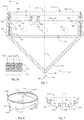
- Figure 1 shows an embodiment of a foundation pile assembly 1 according to the invention.
- the foundation pile assembly 1 extends axially, this means along a central longitudinal axis L, according to a substantially vertical direction and substantially transverse with respect to the ground layer 2.
- terms such as top, bottom, ... or similar expressions are used, then this refers to the illustrated orientation of the foundation pile assembly 1.
- alternative embodiments and/or alternative orientations are possible, for example, wherein the foundation pile assembly is entered under a given angle with respect to the vertical direction and/or not transverse with respect to the ground layer. In such alternative embodiments this terminology should be interpreted in the light of a similar positioning or orientation of the elements of the foundation pile assembly 1 according to the axial direction, this means along the direction of the central longitudinal axis L.
- this embodiment of the foundation pile assembly 1 comprises a steel foundation pile 20.
- the steel foundation pile 20 is an elongated, tubular body, for example, a cylindrical steel tube.
- the steel foundation pile 20 extends axially along a central longitudinal axis L between a bottom end 22 and an opposite top end 24.
- the diameter 26 of the steel foundation pile 20 is less than the length 28 of the foundation pile 20.
- the diameter 26 of the foundation pile 20 is typically in the order of magnitude of 10 cm to 50 cm, but may also range up to, for example, 2 m or 3 m.
- the wall thickness of the steel foundation pile is typically in the range of 1 mm to 10 mm, but may, for example, range up to 25 mm or more, and is therefore typically less than 5 % of the diameter 26 to allow for a sufficiently large central opening in the foundation pile 20 to allow for the feeding of construction material such as concrete.
- the length 28 of a foundation pile 20 is often in the range of 5 m to 35 m, but may range up to, for example, 50 m or more. In any case, the length 28 of the foundation pile 20 is typically a plurality of its diameter 26.
- the foundation pile assembly 1 further comprises a tip 10 which may act as a drill tip.
- the tip 10 is attached to the bottom end 22 of the steel foundation pile 20.
- the tip 10 extends axially, this means along the direction of the central longitudinal axis L, from an attachment side 12 to an opposite tip side 14.
- the tip 10 at the attachment side 12 is connected to the foundation pile 20.
- the opposite tip side 14 is therefore directed away from the foundation pile 20 and in this way forms the bottom end of the foundation pile assembly 1.
- the tip 10 will be first entered into the ground layer, after which the foundation pile 20 follows.
- the foundation pile assembly 1 is entered axially, this means substantially along the direction of the central longitudinal axis L in the ground layer 2. It is clear that furthermore the tip 10 first penetrates the ground layer 2 at its tip side 14, followed by its to the attachment side 12 of the foundation pile 20 connected attachment side 12, and subsequently the foundation pile 20.
- the foundation pile assembly 1 is entered into the ground layer by means of a suitable apparatus.
- a suitable apparatus is known, for example, as a foundation machine, such as, for example, the model IHC Fundex F3500 manufactured by the firm IHC FUNDEX Equipment B.V.
- a foundation machine puts the foundation pile assembly 1 into the ground layer 2, for example, by means of a screw movement.
- a torque K around the central longitudinal axis L, and a pressure force D, along the direction of the central longitudinal axis L, are exerted onto the foundation pile assembly 1.
- the torque K can thereby range up to, for example, 500 kNm and the downward pressure force D can thereby range up to, for example, 50 tons or 500 kN.
- the tip 10 comprises, for an efficient penetration of the ground layer by means of a screw movement, preferably a cone-shaped part 125 of which the point 36 is located at the tip side 14, and/or one or more spiral screw elements.
- the tip 10 serves as drill tip.
- the foundation pile assembly 1 can be entered, for example, only by means of a rectilinear axial movement, along the direction of the central longitudinal axis L, into the ground layer 2. For example, by exerting a continuous or intermittent pressure force D along the central longitudinal axis L, for example, by means of a foundation machine that is equipped with a falling weight to hammer a foundation pile assembly 1 into the ground layer 2.
- the tip 10 at the attachment side 12 is arranged to the bottom end 22 of the steel foundation pile 20 by means of a welded joint 30.
- a welded joint 30 allows this connection to cope with the torque K and/or the pressure force D.
- Such a welded joint is, for example, advantageous in situations wherein the connection between the steel foundation pile 20 and the tip 10 must be sufficiently sealed, for example, to avoid ingress of moisture into the foundation pile assembly 1. This is particularly applicable when the foundation pile assembly 1 is at least partially arranged in for example, a marshy ground layer, swamp layer, water layer, etcetera.
- the foundation pile assembly 1 After entering the foundation pile assembly 1 to a suitable depth in the ground layer 2, for example, the state as shown in the exemplary embodiment of Figure 2 , is reached.
- reinforcing elements, fresh concrete, etcetera or other suitable filler materials are entered at the top end 24 of the steel foundation pile 20, as shown by arrow B.
- the foundation pile assembly 1, this means the tip 10 and the steel foundation pile 20, will then continue to be present along with the on-site formed concrete pile in the ground layer 2.
- the foundation pile assembly 1 comprises a steel foundation pile 20, which is formed by a plurality of steel foundation pile segments which each are welded together at the opposite ends.
- foundation pile segments can then upon entering into the ground layer 2, for example, one by one be connected with their bottom end to the top end of a foundation pile segment already entered, to subsequently reach step by step the desired depth.
- the foundation pile segments can thereby, for example, also be connected by means of a welded joint or any other suitable connection such as a screw connection, a connection with a coupling piece, etcetera. It is clear that the tip 10 will thereby be arranged at the bottom end 22 of the first or bottom steel foundation pile segment of foundation pile 20, for example, by means of a welded joint 30.
- FIG 3 shows in more detail a fragment of the embodiment of the foundation pile assembly 1 of Figures 1 and 2 at the height of the tip 10.
- the tip 10 extends, as a whole, axially from the top attachment side 12 to the bottom tip side 14 along the central longitudinal axis L.
- this central longitudinal axis L also forms the central longitudinal axis for the cast iron tip body 120 and of the element 110 partially molded-in into the cast iron tip body 120, further also called attachment element.
- the tip 10 is therefore formed by an axial succession of the attachment element 110 and the tip body 120.
- the attachment element 110 which is, for example, tubular, extends axially from the top attachment side 12, along the central longitudinal axis L, up to the cast iron tip body 120, and that subsequently the cast iron tip body 120, which, for example, comprises a cone-shaped part 125, extends axially up to the bottom tip side 14, such that the point 36 of the cone-shaped part 125 is located at the bottom.
- the attachment element 110 partially molded-in into the cast iron tip body 120 extends axially from an external end 112 to a molded-in end 114.
- the external end 112 is located at the top and forms the attachment side 12 of the tip 10 as is shown.
- the molded-in end 114 is located as shown, at the bottom of the attachment element 110 and is substantially completely enveloped by the cast iron tip body 120.
- the element 110 partially molded-in into the cast iron tip body 120 thus comprises a molded-in part 116 which extends in the cast iron tip body 120.
- this molded-in part 116 forms the bottom part of the attachment element 110 and this molded-in part 116 is substantially completely enveloped by the cast iron tip body 120.
- this molded-in part 116 is enveloped with this cast iron during the molding process for manufacturing the cast iron tip body 120 since it is enveloped with liquid cast iron of the tip body 120.
- the attachment element 110 also comprises an external part 118 which extends outside of the cast iron tip body 120.
- This external part 118 extends axially from the cast iron tip body 120 in the direction of the attachment side 12 of the tip 10 where it is attached to the external end 112 at the bottom end 22 of the steel foundation pile 20.
- the cast iron tip body 120 extends axially from a top end 122 to a bottom end 124.
- the attachment element 110 thus extends axially out from the top external end 112, past the top end 122 of the cast iron tip body 120, to the bottom molded-in end 114.
- the attachment element 110 consists of a material having a higher melting point than the cast iron of the cast iron tip body 120. It is additionally advantageous if the attachment element 110 consists of a material which can be more easily connected to the bottom end 22 of the foundation pile 20 by means of a welded joint than the cast iron of the cast iron tip body 120. In exemplary embodiments wherein use is made of a steel foundation pile 20, it is therefore advantageous to make use of, for example, a steel attachment element 110.
- the steel type this means, inter alia, the steel alloy, of the steel foundation pile 20 and the steel attachment element 110 correspond or substantially correspond.
- the mass fraction or the mass percentage of carbon or other elements of the steel foundation pile 20 and the steel attachment element 110 are closer to each other than with the corresponding values for the cast iron of the cast iron tip body 120.
- the values for the mass-fraction or mass-percentage for carbon of the steel foundation pile 20 and the steel attachment element 110 correspond substantially.
- the respective values for the mass fraction or the mass percentage for carbon of the steel foundation pile 20 and the steel attachment element 110 differ up to maximum 10%, for example, up to maximum 5%, preferably up to maximum 3% from each other.
- the mass fraction or the mass percentage for carbon of the cast iron tip body 120 will be more than 10%, for example, more than 25%, for example, more than 50% higher than that of the steel foundation pile 20.
- the mass percentage of carbon of the foundation pile 20 and of the attachment element 110 is for example 0,5 % (m/m), and the mass percentage of carbon of the cast iron tip body 120 is for example 3 % (m/m). It is thereby clear that both the steel foundation pile 20 and the steel attachment element 110, for example, are tubular and are not manufactured by means of a molding process, but by means of a process for manufacturing a tubular steel profile or structure, for example, manufactured on the basis of a steel sheet which was subjected to rolling operations and welding operations. According to an embodiment, the steel attachment element 110 may be manufactured using a section of a steel tube, similar to the steel tube which is used for manufacturing the steel foundation pile 20.
- cast iron may be considered as a cast alloy of iron comprising a mass percentage of carbon of more than 2.2 % (m/m), this means a mass fraction for carbon of more than 0.022 kg/kg, for example a value between 0.0350 kg/kg and 0.0385 kg/kg.
- steel may be considered as an iron alloy comprising a mass percentage of carbon of 2.1% (m/m) or less, this means a mass fraction for carbon of 0.021 kg/kg or less.
- m/m mass percentage of carbon of 2.1%
- nodular iron one usually speaks of a carbon content, for example, a mass fraction of 0.035 kg/kg.
- lamellar cast iron one usually speaks of a carbon equivalent, for instance a mass percentage between 3.53% and 3.8%.
- the transverse cross-section of the foundation pile 20 preferably corresponds to the transverse cross-section of the tip 10 at the height of the bottom end 22 of the foundation pile 20.
- transverse cross-section is not circular, but comprises a different suitable shape.
- the respective transverse cross-sections instead of corresponding to each other, are connected to one another, wherein, for example, at the height of the bottom end 22, the attachment element 110 envelopes the foundation pile 20 or vice versa, such that a connection by means of a welded joint can also be realized.
- the respective transverse cross-sections fully correspond, alternative embodiments are possible wherein the respective transverse cross-sections only partially correspond or connect to each other, as long as the corresponding or connected parts allow for a welded joint.
- both the cast iron tip body 120 as well as the partially molded-in steel attachment element 110 extend axially along the central longitudinal axis L of the steel foundation pile 20 is particularly advantageous to efficiently deal with the axial loads that are exerted to enter the foundation pile assembly 1 into the ground layer 2, as well as the load that, after entering in the ground layer 2, is exerted on the foundation pile assembly 1 by the support structure.
- the foundation pile assembly 1 is subjected to a screw movement by applying a torque K around the central longitudinal axis L, this is additionally advantageous to uniformly divide the load as uniform as possible as a result of this torque.
- Figure 4 schematically shows a top view of an embodiment of the tip 10 similar as shown in Figure 3 .
- Figure 5 schematically shows a cross-section of this embodiment of the tip of Figure 4 , along the line V-V in Figure 4 .
- the cast iron tip body 120 comprises a cone-shaped part 125 at the bottom and connects to a cylindrical part 123 at the top.
- both the cylindrical part 123 as the cone-shaped part 125 are hollow, this means provided with a central axial cavity around which a cast iron casing extends itself.
- Such a hollow design is advantageous since this limits the amount of cast iron that needs to be applied for manufacturing the cast iron tip body 120. It is clear that alternative embodiments are possible, wherein one or more parts 123, 125 of the cast iron tip body 120 is not, or only partially provided with such a central axial cavity.
- the cone-shaped part 125 is located at the bottom of the cast iron tip body 120, this means at the bottom end 124 and the orientation of the cone-shaped part 125 is, such that the point 36 is also directed toward the bottom end 124. It is clear that the base of this cone-shaped part 125 is directed toward the opposite top end 122 of the cast iron tip body 120. It is further also clear that this cone-shaped part 125 does not need to comprise a perfect cone-shaped casing surface, it is advantageous if the cast iron tip body 120 comprises a substantially cone-shaped part 125 at the bottom, or comprises a similar shape known to the person skilled in the art that facilitates the penetration of the ground layer 2 during entering of the foundation pile assembly 1.
- the cylindrical part 123 connects, according to the shown embodiment, to the base of the cone-shaped part 125 and this cylindrical part axially extends further to the top end 122 of the cast iron tip body 120.
- the molded-in part 116 of the tubular steel attachment element 110 is molded-in at the top end 122 in this cylindrical part 123.
- the molded-in part 116 of the tubular steel attachment element 110 is substantially completely enveloped by the cast iron of the cast iron tip body 120. This means, as shown, that the cylindrical part 123 of the cast iron tip body 120 extends radially on either side from the tubular attachment element 110.
- the cylindrical part 123 of the cast iron tip body 120 in this manner forms a hollow cylindrical structure which is coaxial with the tubular attachment element 110 and with an outer wall whose diameter is larger than the diameter of the outer wall of the tubular attachment element 110.
- the diameter of the inner wall of the cylindrical part 123 of the cast iron tip body 120 is as shown in turn smaller than the diameter of the inner wall of the tubular attachment element 110.
- the cylindrical part 123 of the cast iron tip body 120 extends according to the shown embodiment axially from the top end 122 of the cast iron tip body 120 until the molded-in end 114 of the attachment element 110, where the cylindrical part 123 connects to and merges into the cone-shaped part 125 of the cast iron tip body 120.
- the molded-in part 116 of the attachment element 110 extends axially from the molded-in end 114 until the top end 122 of the cast iron tip body 120, where it connects to and merges into the external part 118 that extends outside of the cast iron tip body 120.
- the external part 118 of the tubular steel attachment element 110 forms a hollow, cylindrical structure which protrudes axially over a determined distance A, with respect to the top end 122, out of the cast iron tip body 120.
- This distance A is any suitable distance which allows in a simple manner to arrange the external part 118 of the tubular steel attachment element 110 by means of a welded joint to the bottom end 22 of the steel foundation pile 20, for example, 1 cm or more, more in particular 3 cm or more.
- the molded-in part 116 of the tubular steel attachment element 110 comprises a plurality of openings 142 which extend radially through the hollow cylindrical steel casing of the molded-in part 116 of the tubular steel attachment element 110. Since the molded-in part 116 in the cast iron tip body 120 is molded in, the cast iron of the cast iron tip body 120 extends through the radial openings 142 and it thereby fills up these radial openings 142. According to the shown exemplary embodiment, the cylindrical part 123 of the cast iron tip body 120 located radially on either side of the tubular steel attachment element 110, is thus anchored through these openings to the tubular steel attachment element 110.
- FIG 16 schematically shows a cross-section along the line VB-VB of the indicated fragment from Figure 5 .
- Such an anchoring of the cast iron tip body 120 to the tubular steel attachment element 110 allows, for example, for the exchange of high forces and/or torques between the attachment element 110 and the tip body 120 to reduce the risk of separation of the tip body 120 from the attachment element 110.
- the number and the positioning of the openings 142 can vary, as long as one or more openings 142 radially extend through the steel casing of the molded-in part 116 of the tubular steel attachment element 110.
- the openings 142 do not need to extend completely through the steel casing of the molded-in part 116, an anchoring may also be realized when the openings only extend partially radially through the casing, this means radially not completely through the casing of the molded-in part 116. Also in this case the cast iron of the cast iron tip body 120 will extend into these openings in order to realize an anchoring.
- the radial openings are shown with a circular cross-section, according to alternative embodiments suitable radial openings with another suitable cross-section can be used. It is clear that, according to still further alternative embodiments, in addition to openings, one or more suitable recesses, protrusions, etcetera that extend at least partially radially are also able to achieve similar anchorings.
- Figures 6 and 7 further show two versions of a tubular steel attachment element 110 for a tip body 120, similar to that described above.
- the molded-in part near the molded-in end 114 of the attachment element 110 comprises a plurality of recesses 144 and protrusions 146 which at least partially extend axially. It is clear that these recesses and protrusions, in particular, are advantageous to realize an anchoring between the tip body 120 and the molded-in part 116 of the attachment element 110 which reduces the risk that at the exchange of high torques the tip body 120 and the molded-in part 116 separate from each other.
- the recesses 144 and protrusions 146 axially extend at a determined distance from the central longitudinal axis L, that is to say, eccentrically with respect to the central longitudinal axis L.
- one or more openings are provided in the molded-in part 116, which extend at least partially axially, eccentrically with respect to the central longitudinal axis L.
- the molded-in part 116 of the attachment element 110 comprises at least partially radial openings 142, as well as recesses or protrusions, as shown, for example, in Figures 4 and 5 which are combined with at least partially axially extending recesses 144, protrusions 146, or openings, such as, for example, shown in Figures 6 and 7 .
- the cast iron tip body 120 can be provided with one or more, not shown, spiral ribs or taps. It is clear that such ribs are configured to possibly support the entering of the foundation pile assembly 1 by means of a screw movement. It is clear that embodiments of such spiral ribs can be carried out, for example, similar to spiral ribs as known to the person skilled in the art as known from, for example, US4623025 , EP0855489 , WO2011/ 075772 , etcetera. The fact that the tip body 120 is a cast iron tip body 120, thereby allows to manufacture a tip 10 in a simple, flexible and efficient manner, wherein no compromises are necessary with regard to the design of such spiral ribs.
- the cast iron tip body 120 Even when these ribs comprise a complex design, time after time, can be manufactured with a simple molding operation, without the need for complex operations, such as cutting operations, welding operations, and the like to manufacture such ribs and/or to arrange to the tip. It is further clear that the ribs and/or the taps thereto are arranged in a known manner to the outer casing and/or to the bottom side of the tip 10.
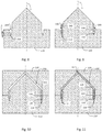
- FIGS 8 to 11 show different steps of an embodiment of a method for manufacturing a tip 10 similarly as described above. Similar parts of the tip 10 are indicated with similar references and will only be described over again in so far as it is relevant to the method for manufacturing the tip 10.
- a lower sand mold 210 for a mold 200 is provided for the cast iron tip body 120.
- the mold 200 comprises a recess 218.
- This recess 218 corresponds to the external part 118 of the attachment element 110.
- this recess 218 which extends as a hollow cylinder, coaxially with the central longitudinal axis L of the mold 200 for the cast iron tip body 120.
- This recess therefore extends axially over the determined distance A in the mold 200, wherein this determined distance A corresponds to the determined distance A (shown in Figure 5 ) at which the external part 118 axially protrudes from the cast iron tip body 120.
- the external part 118 of the attachment element 110 is arranged in the recess 218. It is clear that the external part 118 of the attachment element 110 is arranged in the recess, such that the molded-in part 116 extends, as shown in the mold 200 of the cast iron tip body 120.
- the mold 200 for the cast iron tip body 120 is subsequently completed by providing an upper sand mold 220 and subsequently, as shown in Figure 11 , liquid cast iron is molded in the mold 200, such that the molded-in part 116 of the steel attachment element 110 is molded in.
- FIG 12 shows an alternative embodiment of a foundation pile assembly 1 in a similar position as shown in Figure 1 , this means for the entering of the foundation pile assembly 1 into the ground layer 2.
- the shown foundation pile assembly 1 is similar to the embodiments described above and similar elements are indicated with a similar reference and will only be repeated here in order to indicate the differences.
- the foundation pile assembly 1 also comprises a foundation pile 20 axially extending along a central longitudinal axis L with a tip 10 at its bottom end 22.
- the tip 10 also comprises an element 130 partially molded-in into the cast iron tip body 120, further also called tip element, however this partially molded-in element 130 is now located at the tip side 14 of the tip 10.
- the element 130 partially molded-in into the cast iron tip body 120 at the tip side 14 of the tip 10 is arranged as a tip element 130 for the foundation pile 20.
- the foundation pile 20 can be designed as a pre-manufactured steel or concrete foundation pile, at which the tip 10 is arranged at its bottom end 22.
- the shown embodiment of the tip 10 comprises at its attachment side 12 a cast iron tip body 120 which connects to the bottom end 22 of the foundation pile 20, and as it were forms a foot or support surface for the foundation pile 20.
- the tip 10 can, for example, be anchored to the foundation pile 20 in a mechanical manner.
- the tip element 130 is partially molded-in in this cast iron tip body 120. It is clear that the tip element 130 has a transverse cross-section which is smaller than the transverse cross-section of the foundation pile 20. It is known to the person skilled in the art that such a tip element 130 is advantageous during the entering of the foundation pile assembly 1, but especially to provide a reliable supporting point in a rocky soil, such as known from FI85901B . As shown, both the foundation pile 20, the cast iron tip body 120 and the tip element 130 are preferably arranged coaxially.
- the cast iron tip body 120 of the tip 10, as well as the foundation pile 20 both comprise a rather square or rectangular transverse cross-section and the foundation pile 20 is therefore rather beam-shaped.
- the cast iron tip body is rather pyramidal here, wherein the point of the pyramid shape is directed downward, and the partially molded-in tip element 130 rather corresponds to a full cylindrical shape.
- a foundation pile assembly 1 during entering into the ground layer will, for example, only be subjected to a pressure force D, and will not be exposed to a torque around the central longitudinal axis L.
- the foundation pile 20 is tubular and wherein the tip 10 also comprises a suitable form to allow for a screw movement around the central longitudinal axis L as a result of a torque.
- the tip element 130 also comprises a molded-in part 136 and an external part 138.
- the molded-in part 136 is, as shown substantially completely enveloped by the cast iron of the cast iron tip body 120.
- the external part 138 extends outside of the cast iron tip body 120. However, this time the external part 138 extends axially at the tip side 14 of the tip 10.
- the molded-in part 136 of the tip element 130 comprises a recess 148 which extends partially radially into the molded-in part 136.
- this recess 148 ensures for an improved anchoring of the tip element 130 in the cast iron tip body 120 to be able to withstand high axial pressure forces D with a reduced risk that the tip element 130 separates from the tip body 120. It is thereby clear that the tip element 130 partially molded-in into the cast iron tip body 120 extends axially from an external end 132 to a molded-in end 134.
- the tip element 130 when the tip-element 130 forms the supporting point for the foundation pile assembly 1, because the molded-in part 136 of the tip element 130 is substantially completely enveloped by the cast iron of the cast iron tip body 120, the tensions can be distributed very uniformly from the tip element 130, through the cast iron tip body 120 until the bottom end 22 of the foundation pile 20, such that local peak loads are reduced. This is possible since, due to the partial molding-in of the tip element 130 in the cast iron tip body 120, no recess and associated tolerance must be provided in the tip body 120 to be able to arrange the tip element 130 afterwards. It is clear that the tip element 130, for example, can be manufactured from steel.
- this embodiment of the tip 10 can be manufactured according to a method wherein a mold 200 is provided for the cast iron tip body 120 with a recess corresponding to the external part 138 of the tip element 130, after which this external part 138 is arranged in the recess of the mold, such that the molded-in part 136 extends in the mold 200 for the cast iron tip body 120. Subsequently, liquid cast iron is then molded in the mold 200, such that the cast iron tip body 120 is formed, wherein the molded-in part 136 of the tip element 130 is molded-in. This allows to manufacture such a tip 10 in a simple manner without the need for separate operations or fixing elements for the arrangement of the tip element 130 in the cast iron tip body 120.
- a tip body 120 according to the invention can be provided with several elements partially molded-in in the cast iron tip body 120, for example, both with an attachment element 110 and with a tip element 130.
- the shown embodiment is similar to the embodiment shown in Figures 13 and 14 . Similar elements are shown with similar references and function in general similarly as described above.
- the bottom view of this embodiment is identical to, for example, the bottom view shown in Figure 14.
- Figure 15 shows a partial cross-section along the line XV-XV in Figure 14 of this alternative embodiment.
- the tip 10 comprises at its tip side 14 an element 130 partially molded-in into the tip body 120.
- This alternative embodiment comprises, at the attachment side 12 of the tip 10, an element 110 partially molded-in into the tip body 120, for example, a steel attachment element 110 for the attachment of a steel foundation pile 20.
- the attachment element 110 is hereby attached to a casing surface of the foundation pile 20 by means of a welded joint 30. It is clear that the casing surface of the foundation pile 20 connects at least partially to the inner surface of the attachment element 110 at the height of the welded joint 30.
- the foundation pile 20 is as it were, at the height of its bottom end 22 partially slid into the attachment element 110. It is clear that a number of variant embodiments, similar to the embodiment shown in Figure 15 , are possible.
- the foundation pile 20 and the associated attachment element 110 may have a corresponding cross-section that allows by means of a welded joint 30 to be connected in line, likewise similarly as described in the embodiments shown in Figures 1 to 3 .
Landscapes
- Engineering & Computer Science (AREA)
- Structural Engineering (AREA)
- Life Sciences & Earth Sciences (AREA)
- General Life Sciences & Earth Sciences (AREA)
- Mining & Mineral Resources (AREA)
- Paleontology (AREA)
- Civil Engineering (AREA)
- General Engineering & Computer Science (AREA)
- Piles And Underground Anchors (AREA)
Description
- The invention relates to a tip, more in particular to a tip for attachment to a bottom end of a foundation pile. The invention also relates to a method for manufacturing such a tip, as well as a foundation pile assembly that makes use of such a tip.
- A tip for an on-site formed foundation pile assembly is, for example, known from
US4623025 andEP0855489 . Such a tip is also called drill tip, and is attached to the bottom end of a foundation pile. The tip is preferably designed as a cast iron structure since this facilitates the production of a suitable shape, in particular of, for example, spiral ribs which are arranged to the surface of the tip. In order to couple the tip to the bottom end of the foundation pile, the tip is provided with cam-shaped structures that couple into corresponding recesses at the bottom end of the foundation pile. This offers the advantage that the foundation pile can be removed again after the formation of an on-site poured concrete foundation pile, such that only the tip and the concrete foundation pile remain behind in the ground layer. However, for certain applications, for example, wherein the foundation pile assembly is used in an environment with a water layer, a swampy area, etcetera there is the need to make use of a tip that is fixedly coupled to the foundation pile assembly to avoid inflow of water into the foundation pile assembly during entering into the ground layer and during the formation of an on-site formed concrete foundation pile. In addition, there is also the desire to achieve an improved anchoring of the tip to the bottom end of the foundation pile in an effort to be able to withstand higher pressure forces and torques upon entering of the foundation pile assembly in the ground layer. - Furthermore, it is not easy to achieve a welded joint between a cast iron tip and a steel foundation pile at a construction site where a foundation pile assembly should be assembled on the basis of delivered foundation piles and tips as this requires welding operations and associated equipment which are normally not at disposal at a construction site.
- A tip for a foundation pile is further known from
FI85901B - Furthermore, a tip is also known from
WO2011/075772 , wherein in an exemplary embodiment is described that, in order to allow the welding of a tip to a foundation pile, it is desirable to manufacture the tip from cast steel. However, cast steel is a much more expensive material than cast iron. Such a cast steel tip is also more difficult to manufacture since the molding process, for example, requires higher melting temperatures. - In
FR424043 - In the context of this application, the term cast steel shall mean a cast alloy of iron comprising a mass percentage of carbon of less than 2.1% (m/m), this means a mass fraction of carbon of less than 0.021 kg/kg. Cast iron is, in the context of this application, a cast alloy of iron comprising a mass percentage of carbon of more than 2.2 % (m/m), this means a mass fraction of carbon of more than 0.022 kg/kg, for example, a mass fraction of 0.030 kg/kg or more, in particular a mass fraction of 0.035 kg/kg or more. Depending on the type of cast iron, one may speak of a carbon content or carbon equivalent. For example, with nodular cast iron, for example, one speaks of a carbon content of 0.035 kg/kg. For example, with lamellar cast iron, for example, one speaks of a carbon equivalent between 3.53 % and 3.8 %.
- Consequently, there exists a need for a tip which is simple to manufacture and which enables a foundation pile assembly with a simplified and improved anchoring.
- For this purpose, according to a first aspect of the invention, a tip is provided for attachment to a bottom end of a foundation pile, wherein the tip comprises a cast iron tip body. The tip further comprises an element partially molded-in into the cast iron tip body. The element partially molded-in into the cast iron tip body comprises a molded-in part which extends into the cast iron tip body and is enveloped by the cast iron of the cast iron tip body. The element partially molded-in into the cast iron tip body comprises an external part which extends outside the cast iron tip body. The tip is characterized in that the molded-in part of the partially molded-in element comprises one or more openings which extend at least partially radially with respect to the central longitudinal axis of the tip and/or at least partially axially, eccentrically with respect to the central longitudinal axis of the tip.
- The partially molded-in element is directly enveloped with and adheres very closely to the cast iron of the cast iron tip body, which realizes a simplified and improved anchoring. Furthermore, in this way a tip is realized that can be manufactured by means of a simple molding process. In this manner an improved anchoring is realized which allows to withstand high loads and/or torques, for example, upon entering of the foundation pile into the ground layer.
- According to an embodiment, a tip is provided, characterized in that:
- the tip extends axially from a top attachment side for the attachment of the foundation pile to an opposite bottom tip side along a central longitudinal axis;
- the cast iron tip body also extends axially along the central longitudinal axis of the tip, from a top end to a bottom end; and
- the element partially molded-in into the cast iron tip body also extends axially along the central longitudinal axis of the tip, from an external end toward a molded-in end.
- In this manner, the tip can withstand high loads and torques in an efficient manner, for example, upon entering of the foundation pile assembly into the ground layer.
- The element partially molded-in into the cast iron tip body:
- comprises a molded-in part which extends into the cast iron tip body and is enveloped by the cast iron of the cast iron tip body; and
- comprises an external part which extends outside the cast iron tip body.
- In this manner an improved anchoring between the molded-in element and the tip body is enabled in a simple manner.
- According to a further embodiment, a tip is provided, characterized in that the element partially molded-in into the cast iron tip body consists of a material having a higher melting point than the cast iron of the cast iron tip body.
- In this manner, the partially molded-in element, which is manufactured, for example, from steel or another suitable metal alloy, can be arranged without risk of undesirable deformation at the tip.
- According to a further embodiment, a tip is provided, characterized in that the molded-in part:
- comprises one or more recesses and/or protrusions which at least partially extend radially; and/or
- comprises one or more recesses and/or protrusions which at least partially extend axially, eccentrically with respect to the central longitudinal axis.
- In this manner an improved anchoring is realized which allows to withstand high loads and/or torques, for example, upon entering of the foundation pile into the ground layer.
- According to a further embodiment, a tip is provided, wherein the tip is configured for attachment to a steel foundation pile by means of a welded joint, characterized in that the element partially molded-in into the cast iron tip body is a steel attachment element which is arranged at the attachment side of the tip.
- In this manner, a good sealed connection between the tip and the foundation pile can be realized in a simple and efficient manner at a construction site, without the need for complex welding operations and associated devices.
- According to a further embodiment a tip is provided, characterized in that the steel attachment element is tubular.
- This is advantageous since such a steel tubular shape is easily connectable to the steel tubular shape of a foundation pile.
- According to a further embodiment a tip is provided, characterized in that the cast iron tip body:
- comprises a cylindrical part at the top end, wherein the molded-in part of the tubular steel attachment element is molded-in; and/or
- comprises a cone-shaped part, of which the point is located at the bottom end.
- Such a design allows to easily mold-in a tubular attachment element at the top end, and in order to achieve an efficient penetration of the ground layer to the bottom end.
- According to a further embodiment, a tip is provided, characterized in that the cast iron tip body comprises one or more spiral ribs.
- This ensures an efficient penetration of the ground layer during entering of the foundation pile assembly by means of a screw movement.
- According to further embodiment, a tip is provided, characterized in that the element partially molded-in into the cast iron tip body, is arranged at the tip side of the tip as a tip element for the foundation pile.
- In this manner, such a type of foundation pile assembly is realized in a simple manner with an optimum anchoring and distribution of the tensions since the tip element is directly enveloped by the cast iron of the tip body.
- According to a second aspect of the invention, a foundation pile assembly is provided, comprising a tip according to the first aspect of the invention, characterized in that the foundation pile assembly further comprises a foundation pile, and wherein the tip is attached to a bottom end of the foundation pile.
- The partially molded-in element is enveloped directly with and fits very closely on the cast iron of the cast iron tip body, such that a simplified and improved anchoring is realized, wherein, for example during entering of the foundation pile assembly, higher loads and torques can be withstood.
- According to a further embodiment, a foundation pile assembly is provided, characterized in that, at the height of the bottom end, the transverse cross-section of the foundation pile at least partially connects to or corresponds to the cross-section of the tip.
- This allows to connect the foundation pile with the tip in a simple manner, for example, by means of a welded joint.
- According to a further embodiment, a foundation pile assembly is provided, characterized in that the tip is attached to the steel foundation pile by means of a welded joint.
- Particularly, when the tip comprises a steel attachment element at its top end, then it becomes possible to arrange the tip at the bottom end of a steel foundation pile in a simple manner by means of a welded joint with simple equipment that is present at the construction site.
- According to a third aspect of the invention, a method for manufacturing a tip according to the first aspect of the invention is provided, characterized in that the method comprises the following steps:
- providing a mold for the cast iron tip body comprising a recess corresponding to the external part of the partially molded-in element,
- arranging the external part of the partially molded-in element in the recess of the mold, so that the molded-in part extends into the mold for the cast iron tip body; and
- subsequently, molding liquid cast iron into the mold for the cast iron tip body, so that the molded-in part of the element is molded in.
- This allows to manufacture the tip by means of a simple molding process and the recess thereby ensures that the partially molded-in element is positioned in a correct manner with respect to the tip body.
- According to a further embodiment, a method for manufacturing a tip is provided, characterized in that the method comprises the following steps:
- providing a lower sand mold for the mold, the lower sand mold comprising the recess;
- subsequently arranging the external part of the element in the recess;
- subsequently completing the mold by providing an upper sand mold; and
- subsequently molding liquid cast iron into the mold, so that the molded-in part of the element is molded in.
- The use of a lower sand mold and upper sand mold facilitates the arrangement of the external part of the element in the recess.
- According to a fourth aspect of the invention, a method for manufacturing a foundation pile assembly according to the second aspect of the invention is provided, wherein the tip is arranged by means of a molded-in steel attachment element partially molded-in into the cast iron tip body, to the bottom end of the steel foundation pile by means of a welded joint.
- In this manner, the tip can be arranged in a simple manner, at the construction site, by means of a welded joint to the bottom end of the foundation pile, without the need for complex welding equipment.
- The invention will hereinafter be further described with reference to embodiments shown in the drawings, wherein:
-
Figure 1 schematically shows an embodiment of a foundation pile assembly according to the invention in a state before entering into a ground layer; -
Figure 2 schematically shows the embodiment ofFigure 1 in a state after the foundation pile assembly was entered into the ground layer; -
Figure 3 schematically shows a fragment of the embodiment of thefoundation pile assembly 1 ofFigures 1 and 2 at the height of the tip in more detail; -
Figure 4 schematically shows a top view of an embodiment of the tip similar as shown inFigure 3 ; -
Figure 5 schematically shows a sectional view of the embodiment of the tip ofFigure 4 , along the line V-V inFigure 4 ; -
Figures 6 and 7 schematically show alternative embodiments of an attachment element for the tip; -
Figures 8 to 11 schematically show different steps of an embodiment for manufacturing an embodiment of the tip similar as shown inFigures 1 to 7 ; -
Figure 12 shows an alternative embodiment of a foundation pile assembly in a similar state as shown inFigure 1 ; -
Figure 13 schematically shows a fragment similar toFigure 3 of the embodiment ofFigure 12 ; -
Figure 14 schematically shows a bottom view of the tip of the foundation pile assembly ofFigure 12 ; and -
Figure 15 shows a partial section view along the line XV-XV inFigure 14 of an alternative embodiment of the foundation pile assembly ofFigure 13 , with a similar bottom view as shown inFigure 14 ; -
Figure 16 shows a sectional view of a fragment ofFigure 5 along the line VB-VB. -
Figure 1 shows an embodiment of afoundation pile assembly 1 according to the invention. In the state shown, thefoundation pile assembly 1 extends axially, this means along a central longitudinal axis L, according to a substantially vertical direction and substantially transverse with respect to the ground layer 2. When, in the following description, terms such as top, bottom, ... or similar expressions are used, then this refers to the illustrated orientation of thefoundation pile assembly 1. It goes without saying that alternative embodiments and/or alternative orientations are possible, for example, wherein the foundation pile assembly is entered under a given angle with respect to the vertical direction and/or not transverse with respect to the ground layer. In such alternative embodiments this terminology should be interpreted in the light of a similar positioning or orientation of the elements of thefoundation pile assembly 1 according to the axial direction, this means along the direction of the central longitudinal axis L. - As shown in
Figure 1 , this embodiment of thefoundation pile assembly 1 comprises asteel foundation pile 20. The steel foundation pile 20 is an elongated, tubular body, for example, a cylindrical steel tube. As shown, the steel foundation pile 20 extends axially along a central longitudinal axis L between abottom end 22 and an oppositetop end 24. As is further shown, thediameter 26 of the steel foundation pile 20 is less than thelength 28 of thefoundation pile 20. Thediameter 26 of thefoundation pile 20 is typically in the order of magnitude of 10 cm to 50 cm, but may also range up to, for example, 2 m or 3 m. The wall thickness of the steel foundation pile is typically in the range of 1 mm to 10 mm, but may, for example, range up to 25 mm or more, and is therefore typically less than 5 % of thediameter 26 to allow for a sufficiently large central opening in thefoundation pile 20 to allow for the feeding of construction material such as concrete. Thelength 28 of afoundation pile 20 is often in the range of 5 m to 35 m, but may range up to, for example, 50 m or more. In any case, thelength 28 of thefoundation pile 20 is typically a plurality of itsdiameter 26. - As shown in
Figure 1 , thefoundation pile assembly 1 further comprises atip 10 which may act as a drill tip. Thetip 10 is attached to thebottom end 22 of thesteel foundation pile 20. As can be seen, thetip 10 extends axially, this means along the direction of the central longitudinal axis L, from anattachment side 12 to anopposite tip side 14. As shown, thetip 10 at theattachment side 12 is connected to thefoundation pile 20. Theopposite tip side 14 is therefore directed away from thefoundation pile 20 and in this way forms the bottom end of thefoundation pile assembly 1. As will be further clarified, during entering of thefoundation pile assembly 1, thetip 10 will be first entered into the ground layer, after which thefoundation pile 20 follows. In addition, thefoundation pile assembly 1 is entered axially, this means substantially along the direction of the central longitudinal axis L in the ground layer 2. It is clear that furthermore thetip 10 first penetrates the ground layer 2 at itstip side 14, followed by its to theattachment side 12 of thefoundation pile 20connected attachment side 12, and subsequently thefoundation pile 20. - Preferably, the
foundation pile assembly 1 is entered into the ground layer by means of a suitable apparatus. Such an apparatus is known, for example, as a foundation machine, such as, for example, the model IHC Fundex F3500 manufactured by the firm IHC FUNDEX Equipment B.V. Such a foundation machine puts thefoundation pile assembly 1 into the ground layer 2, for example, by means of a screw movement. Thereby, as shown inFigure 1 , a torque K, around the central longitudinal axis L, and a pressure force D, along the direction of the central longitudinal axis L, are exerted onto thefoundation pile assembly 1. The torque K can thereby range up to, for example, 500 kNm and the downward pressure force D can thereby range up to, for example, 50 tons or 500 kN. As known by a person skilled in the art, and further shown in more detail, thetip 10 comprises, for an efficient penetration of the ground layer by means of a screw movement, preferably a cone-shapedpart 125 of which thepoint 36 is located at thetip side 14, and/or one or more spiral screw elements. Here thetip 10 serves as drill tip. It goes without saying that according to alternative embodiments, thefoundation pile assembly 1, can be entered, for example, only by means of a rectilinear axial movement, along the direction of the central longitudinal axis L, into the ground layer 2. For example, by exerting a continuous or intermittent pressure force D along the central longitudinal axis L, for example, by means of a foundation machine that is equipped with a falling weight to hammer afoundation pile assembly 1 into the ground layer 2. - With to the embodiment of the
foundation pile assembly 1 shown inFigure 1 , thetip 10 at theattachment side 12 is arranged to thebottom end 22 of the steel foundation pile 20 by means of a welded joint 30. Such a welded joint 30 allows this connection to cope with the torque K and/or the pressure force D. Such a welded joint is, for example, advantageous in situations wherein the connection between thesteel foundation pile 20 and thetip 10 must be sufficiently sealed, for example, to avoid ingress of moisture into thefoundation pile assembly 1. This is particularly applicable when thefoundation pile assembly 1 is at least partially arranged in for example, a marshy ground layer, swamp layer, water layer, etcetera. - After entering the
foundation pile assembly 1 to a suitable depth in the ground layer 2, for example, the state as shown in the exemplary embodiment ofFigure 2 , is reached. According to an exemplary embodiment hereinafter, for example, reinforcing elements, fresh concrete, etcetera or other suitable filler materials are entered at thetop end 24 of thesteel foundation pile 20, as shown by arrow B. Thefoundation pile assembly 1, this means thetip 10 and thesteel foundation pile 20, will then continue to be present along with the on-site formed concrete pile in the ground layer 2. It goes without saying that many variant embodiments are possible, such as, for example, embodiments wherein thefoundation pile assembly 1, comprises asteel foundation pile 20, which is formed by a plurality of steel foundation pile segments which each are welded together at the opposite ends. These foundation pile segments can then upon entering into the ground layer 2, for example, one by one be connected with their bottom end to the top end of a foundation pile segment already entered, to subsequently reach step by step the desired depth. The foundation pile segments can thereby, for example, also be connected by means of a welded joint or any other suitable connection such as a screw connection, a connection with a coupling piece, etcetera. It is clear that thetip 10 will thereby be arranged at thebottom end 22 of the first or bottom steel foundation pile segment offoundation pile 20, for example, by means of a welded joint 30. -
Figure 3 shows in more detail a fragment of the embodiment of thefoundation pile assembly 1 ofFigures 1 and 2 at the height of thetip 10. Thetip 10 extends, as a whole, axially from thetop attachment side 12 to thebottom tip side 14 along the central longitudinal axis L. As shown, this central longitudinal axis L also forms the central longitudinal axis for the castiron tip body 120 and of theelement 110 partially molded-in into the castiron tip body 120, further also called attachment element. As shown, thetip 10 is therefore formed by an axial succession of theattachment element 110 and thetip body 120. This means that theattachment element 110, which is, for example, tubular, extends axially from thetop attachment side 12, along the central longitudinal axis L, up to the castiron tip body 120, and that subsequently the castiron tip body 120, which, for example, comprises a cone-shapedpart 125, extends axially up to thebottom tip side 14, such that thepoint 36 of the cone-shapedpart 125 is located at the bottom. It is thereby clear that theattachment element 110 partially molded-in into the castiron tip body 120 extends axially from anexternal end 112 to a molded-inend 114. Theexternal end 112 is located at the top and forms theattachment side 12 of thetip 10 as is shown. The molded-inend 114 is located as shown, at the bottom of theattachment element 110 and is substantially completely enveloped by the castiron tip body 120. Theelement 110 partially molded-in into the castiron tip body 120 thus comprises a molded-inpart 116 which extends in the castiron tip body 120. As shown, this molded-inpart 116 forms the bottom part of theattachment element 110 and this molded-inpart 116 is substantially completely enveloped by the castiron tip body 120. As further on will be explained in more detail, it is clear that this molded-inpart 116 is enveloped with this cast iron during the molding process for manufacturing the castiron tip body 120 since it is enveloped with liquid cast iron of thetip body 120. After the solidification of the cast iron of thetip body 120, a connection between theattachment element 110 and the castiron tip body 120 is achieved in this manner. As further shown, theattachment element 110 also comprises anexternal part 118 which extends outside of the castiron tip body 120. Thisexternal part 118 extends axially from the castiron tip body 120 in the direction of theattachment side 12 of thetip 10 where it is attached to theexternal end 112 at thebottom end 22 of thesteel foundation pile 20. As is further shown the castiron tip body 120 extends axially from atop end 122 to abottom end 124. As shown theattachment element 110 thus extends axially out from the topexternal end 112, past thetop end 122 of the castiron tip body 120, to the bottom molded-inend 114. - In order to partially mold the
attachment element 110 into the castiron tip body 120, it is advantageous that theattachment element 110 consists of a material having a higher melting point than the cast iron of the castiron tip body 120. It is additionally advantageous if theattachment element 110 consists of a material which can be more easily connected to thebottom end 22 of thefoundation pile 20 by means of a welded joint than the cast iron of the castiron tip body 120. In exemplary embodiments wherein use is made of asteel foundation pile 20, it is therefore advantageous to make use of, for example, asteel attachment element 110. Preferably, the steel type, this means, inter alia, the steel alloy, of thesteel foundation pile 20 and thesteel attachment element 110 correspond or substantially correspond. This means, for example, that the mass fraction or the mass percentage of carbon or other elements of thesteel foundation pile 20 and thesteel attachment element 110 are closer to each other than with the corresponding values for the cast iron of the castiron tip body 120. Preferably, the values for the mass-fraction or mass-percentage for carbon of thesteel foundation pile 20 and thesteel attachment element 110, correspond substantially. This means that the respective values for the mass fraction or the mass percentage for carbon of thesteel foundation pile 20 and thesteel attachment element 110 differ up to maximum 10%, for example, up to maximum 5%, preferably up to maximum 3% from each other. Typically, the mass fraction or the mass percentage for carbon of the castiron tip body 120 will be more than 10%, for example, more than 25%, for example, more than 50% higher than that of thesteel foundation pile 20. According to an exemplary embodiment, the mass percentage of carbon of thefoundation pile 20 and of theattachment element 110 is for example 0,5 % (m/m), and the mass percentage of carbon of the castiron tip body 120 is for example 3 % (m/m). It is thereby clear that both thesteel foundation pile 20 and thesteel attachment element 110, for example, are tubular and are not manufactured by means of a molding process, but by means of a process for manufacturing a tubular steel profile or structure, for example, manufactured on the basis of a steel sheet which was subjected to rolling operations and welding operations. According to an embodiment, thesteel attachment element 110 may be manufactured using a section of a steel tube, similar to the steel tube which is used for manufacturing thesteel foundation pile 20. - However, it is clear that alternative embodiments are possible, as long as in general the
attachment element 110 is manufactured from a material that can be attached easier and simpler to the steel foundation pile 20 by means of a welded joint. This facilitates the on-site attachment of thetip 10 at the bottom end of thefoundation pile 20 at the construction site itself, without the need for providing special welding techniques, apparatuses, etcetera. In general, in the context of this application, cast iron may be considered as a cast alloy of iron comprising a mass percentage of carbon of more than 2.2 % (m/m), this means a mass fraction for carbon of more than 0.022 kg/kg, for example a value between 0.0350 kg/kg and 0.0385 kg/kg. In general, in the context of this application, steel, may be considered as an iron alloy comprising a mass percentage of carbon of 2.1% (m/m) or less, this means a mass fraction for carbon of 0.021 kg/kg or less. With nodular iron one usually speaks of a carbon content, for example, a mass fraction of 0.035 kg/kg. In lamellar cast iron one usually speaks of a carbon equivalent, for instance a mass percentage between 3.53% and 3.8%. - According to the shown exemplary embodiment, the transverse cross-section of the
foundation pile 20 preferably corresponds to the transverse cross-section of thetip 10 at the height of thebottom end 22 of thefoundation pile 20. According to the shown exemplary embodiment, this means that, as further described in more detail, the tube-shapedsteel attachment element 110, transverse to the central longitudinal axis L, shows a cross-section that corresponds to the transverse cross-section of thefoundation pile 20 at the height of thebottom end 22 of thefoundation pile 20. It is clear that thebottom end 22 of thefoundation pile 20 and theexternal end 112 of theattachment element 110 partially molded-in into the castiron tip body 120 in such an embodiment can be welded together in line with each other. However, it is clear that alternative embodiments are possible, for example, wherein the transverse cross-section is not circular, but comprises a different suitable shape. In further alternative embodiments it is, for example, also possible that the respective transverse cross-sections instead of corresponding to each other, are connected to one another, wherein, for example, at the height of thebottom end 22, theattachment element 110 envelopes thefoundation pile 20 or vice versa, such that a connection by means of a welded joint can also be realized. It is clear that, although in the shown exemplary embodiment, the respective transverse cross-sections fully correspond, alternative embodiments are possible wherein the respective transverse cross-sections only partially correspond or connect to each other, as long as the corresponding or connected parts allow for a welded joint. - That both the cast
iron tip body 120 as well as the partially molded-insteel attachment element 110 extend axially along the central longitudinal axis L of the steel foundation pile 20 is particularly advantageous to efficiently deal with the axial loads that are exerted to enter thefoundation pile assembly 1 into the ground layer 2, as well as the load that, after entering in the ground layer 2, is exerted on thefoundation pile assembly 1 by the support structure. In embodiments, such as the shown embodiment, wherein upon entering, thefoundation pile assembly 1 is subjected to a screw movement by applying a torque K around the central longitudinal axis L, this is additionally advantageous to uniformly divide the load as uniform as possible as a result of this torque. -
Figure 4 schematically shows a top view of an embodiment of thetip 10 similar as shown inFigure 3 .Figure 5 schematically shows a cross-section of this embodiment of the tip ofFigure 4 , along the line V-V inFigure 4 . As can be seen inFigures 4 and5 , the castiron tip body 120 comprises a cone-shapedpart 125 at the bottom and connects to acylindrical part 123 at the top. According to the shown embodiment, both thecylindrical part 123 as the cone-shapedpart 125 are hollow, this means provided with a central axial cavity around which a cast iron casing extends itself. Such a hollow design is advantageous since this limits the amount of cast iron that needs to be applied for manufacturing the castiron tip body 120. It is clear that alternative embodiments are possible, wherein one ormore parts iron tip body 120 is not, or only partially provided with such a central axial cavity. - As can be seen in
Figure 5 , the cone-shapedpart 125 is located at the bottom of the castiron tip body 120, this means at thebottom end 124 and the orientation of the cone-shapedpart 125 is, such that thepoint 36 is also directed toward thebottom end 124. It is clear that the base of this cone-shapedpart 125 is directed toward the oppositetop end 122 of the castiron tip body 120. It is further also clear that this cone-shapedpart 125 does not need to comprise a perfect cone-shaped casing surface, it is advantageous if the castiron tip body 120 comprises a substantially cone-shapedpart 125 at the bottom, or comprises a similar shape known to the person skilled in the art that facilitates the penetration of the ground layer 2 during entering of thefoundation pile assembly 1. As can be seen further, thecylindrical part 123 connects, according to the shown embodiment, to the base of the cone-shapedpart 125 and this cylindrical part axially extends further to thetop end 122 of the castiron tip body 120. As can be seen further, according to the shown embodiment, the molded-inpart 116 of the tubularsteel attachment element 110 is molded-in at thetop end 122 in thiscylindrical part 123. As shown, the molded-inpart 116 of the tubularsteel attachment element 110 is substantially completely enveloped by the cast iron of the castiron tip body 120. This means, as shown, that thecylindrical part 123 of the castiron tip body 120 extends radially on either side from thetubular attachment element 110. Thecylindrical part 123 of the castiron tip body 120 in this manner forms a hollow cylindrical structure which is coaxial with thetubular attachment element 110 and with an outer wall whose diameter is larger than the diameter of the outer wall of thetubular attachment element 110. The diameter of the inner wall of thecylindrical part 123 of the castiron tip body 120 is as shown in turn smaller than the diameter of the inner wall of thetubular attachment element 110. Thecylindrical part 123 of the castiron tip body 120 extends according to the shown embodiment axially from thetop end 122 of the castiron tip body 120 until the molded-inend 114 of theattachment element 110, where thecylindrical part 123 connects to and merges into the cone-shapedpart 125 of the castiron tip body 120. The molded-inpart 116 of theattachment element 110 extends axially from the molded-inend 114 until thetop end 122 of the castiron tip body 120, where it connects to and merges into theexternal part 118 that extends outside of the castiron tip body 120. As can be seen, theexternal part 118 of the tubularsteel attachment element 110 forms a hollow, cylindrical structure which protrudes axially over a determined distance A, with respect to thetop end 122, out of the castiron tip body 120. This distance A is any suitable distance which allows in a simple manner to arrange theexternal part 118 of the tubularsteel attachment element 110 by means of a welded joint to thebottom end 22 of thesteel foundation pile 20, for example, 1 cm or more, more in particular 3 cm or more. - As is further shown, the molded-in
part 116 of the tubularsteel attachment element 110 comprises a plurality ofopenings 142 which extend radially through the hollow cylindrical steel casing of the molded-inpart 116 of the tubularsteel attachment element 110. Since the molded-inpart 116 in the castiron tip body 120 is molded in, the cast iron of the castiron tip body 120 extends through theradial openings 142 and it thereby fills up theseradial openings 142. According to the shown exemplary embodiment, thecylindrical part 123 of the castiron tip body 120 located radially on either side of the tubularsteel attachment element 110, is thus anchored through these openings to the tubularsteel attachment element 110. This is, for example, also clearly shown inFigure 16 which schematically shows a cross-section along the line VB-VB of the indicated fragment fromFigure 5 . Such an anchoring of the castiron tip body 120 to the tubularsteel attachment element 110 allows, for example, for the exchange of high forces and/or torques between theattachment element 110 and thetip body 120 to reduce the risk of separation of thetip body 120 from theattachment element 110. It is clear that according to alternative embodiments, the number and the positioning of theopenings 142 can vary, as long as one ormore openings 142 radially extend through the steel casing of the molded-inpart 116 of the tubularsteel attachment element 110. According to yet other alternative embodiments, theopenings 142 do not need to extend completely through the steel casing of the molded-inpart 116, an anchoring may also be realized when the openings only extend partially radially through the casing, this means radially not completely through the casing of the molded-inpart 116. Also in this case the cast iron of the castiron tip body 120 will extend into these openings in order to realize an anchoring. Further it is also clear that, although in the shown exemplary embodiment the radial openings are shown with a circular cross-section, according to alternative embodiments suitable radial openings with another suitable cross-section can be used. It is clear that, according to still further alternative embodiments, in addition to openings, one or more suitable recesses, protrusions, etcetera that extend at least partially radially are also able to achieve similar anchorings. -
Figures 6 and 7 further show two versions of a tubularsteel attachment element 110 for atip body 120, similar to that described above. As shown the molded-in part near the molded-inend 114 of theattachment element 110 comprises a plurality ofrecesses 144 andprotrusions 146 which at least partially extend axially. It is clear that these recesses and protrusions, in particular, are advantageous to realize an anchoring between thetip body 120 and the molded-inpart 116 of theattachment element 110 which reduces the risk that at the exchange of high torques thetip body 120 and the molded-inpart 116 separate from each other. It is thereby clear that therecesses 144 andprotrusions 146 axially extend at a determined distance from the central longitudinal axis L, that is to say, eccentrically with respect to the central longitudinal axis L. According to an embodiment, in addition to recesses or protrusions, one or more openings are provided in the molded-inpart 116, which extend at least partially axially, eccentrically with respect to the central longitudinal axis L. - It is clear that further alternative embodiments are possible wherein the molded-in
part 116 of theattachment element 110 comprises at least partiallyradial openings 142, as well as recesses or protrusions, as shown, for example, inFigures 4 and5 which are combined with at least partially axially extendingrecesses 144,protrusions 146, or openings, such as, for example, shown inFigures 6 and 7 . - According to alternative embodiments not shown, the cast
iron tip body 120 can be provided with one or more, not shown, spiral ribs or taps. It is clear that such ribs are configured to possibly support the entering of thefoundation pile assembly 1 by means of a screw movement. It is clear that embodiments of such spiral ribs can be carried out, for example, similar to spiral ribs as known to the person skilled in the art as known from, for example,US4623025 ,EP0855489 ,WO2011/ 075772 , etcetera. The fact that thetip body 120 is a castiron tip body 120, thereby allows to manufacture atip 10 in a simple, flexible and efficient manner, wherein no compromises are necessary with regard to the design of such spiral ribs. It is sufficient to apply the design of the spiral ribs at the manufacturing of the mold for the castiron tip body 120. Subsequently the castiron tip body 120, even when these ribs comprise a complex design, time after time, can be manufactured with a simple molding operation, without the need for complex operations, such as cutting operations, welding operations, and the like to manufacture such ribs and/or to arrange to the tip. It is further clear that the ribs and/or the taps thereto are arranged in a known manner to the outer casing and/or to the bottom side of thetip 10. -
Figures 8 to 11 show different steps of an embodiment of a method for manufacturing atip 10 similarly as described above. Similar parts of thetip 10 are indicated with similar references and will only be described over again in so far as it is relevant to the method for manufacturing thetip 10. In a step shown inFigure 8 , alower sand mold 210 for amold 200 is provided for the castiron tip body 120. As shown, themold 200 comprises arecess 218. Thisrecess 218 corresponds to theexternal part 118 of theattachment element 110. For the exemplary embodiment described above with a tubularsteel attachment element 110, this therefore means, as shown arecess 218 which extends as a hollow cylinder, coaxially with the central longitudinal axis L of themold 200 for the castiron tip body 120. This recess therefore extends axially over the determined distance A in themold 200, wherein this determined distance A corresponds to the determined distance A (shown inFigure 5 ) at which theexternal part 118 axially protrudes from the castiron tip body 120. - In a next step, as schematically shown in
Figure 9 , theexternal part 118 of theattachment element 110 is arranged in therecess 218. It is clear that theexternal part 118 of theattachment element 110 is arranged in the recess, such that the molded-inpart 116 extends, as shown in themold 200 of the castiron tip body 120. - As shown in
Figure 10 , themold 200 for the castiron tip body 120 is subsequently completed by providing anupper sand mold 220 and subsequently, as shown inFigure 11 , liquid cast iron is molded in themold 200, such that the molded-inpart 116 of thesteel attachment element 110 is molded in. - Although the above method for manufacturing a
tip 10 makes use of alower sand mold 210 and anupper sand mold 220 it is clear that alternative embodiments for themold 200 are possible, such as, for example, alternative embodiments of sand molding, molding processes which make use of permanent molds, etcetera. It is thereby clear that a correct positioning of theattachment element 110 that is partially molded-in in the castiron tip body 120 is ensured by the positioning of theexternal part 118 of theattachment element 110 into thecorresponding recess 218 of themold 200. -
Figure 12 shows an alternative embodiment of afoundation pile assembly 1 in a similar position as shown inFigure 1 , this means for the entering of thefoundation pile assembly 1 into the ground layer 2. The shownfoundation pile assembly 1 is similar to the embodiments described above and similar elements are indicated with a similar reference and will only be repeated here in order to indicate the differences. As shown thefoundation pile assembly 1 also comprises afoundation pile 20 axially extending along a central longitudinal axis L with atip 10 at itsbottom end 22. Thetip 10 also comprises anelement 130 partially molded-in into the castiron tip body 120, further also called tip element, however this partially molded-inelement 130 is now located at thetip side 14 of thetip 10. - As is shown in more detail in
Figure 13 , theelement 130 partially molded-in into the castiron tip body 120 at thetip side 14 of thetip 10 is arranged as atip element 130 for thefoundation pile 20. For example, according to an embodiment, thefoundation pile 20 can be designed as a pre-manufactured steel or concrete foundation pile, at which thetip 10 is arranged at itsbottom end 22. As can be seen, the shown embodiment of thetip 10 comprises at its attachment side 12 a castiron tip body 120 which connects to thebottom end 22 of thefoundation pile 20, and as it were forms a foot or support surface for thefoundation pile 20. Thetip 10 can, for example, be anchored to thefoundation pile 20 in a mechanical manner. At thebottom end 22 thetip element 130 is partially molded-in in this castiron tip body 120. It is clear that thetip element 130 has a transverse cross-section which is smaller than the transverse cross-section of thefoundation pile 20. It is known to the person skilled in the art that such atip element 130 is advantageous during the entering of thefoundation pile assembly 1, but especially to provide a reliable supporting point in a rocky soil, such as known fromFI85901B foundation pile 20, the castiron tip body 120 and thetip element 130 are preferably arranged coaxially. As can be seen in the bottom view ofFigure 14 , the castiron tip body 120 of thetip 10, as well as thefoundation pile 20 both comprise a rather square or rectangular transverse cross-section and thefoundation pile 20 is therefore rather beam-shaped. As shown the cast iron tip body is rather pyramidal here, wherein the point of the pyramid shape is directed downward, and the partially molded-intip element 130 rather corresponds to a full cylindrical shape. It is clear that such afoundation pile assembly 1 during entering into the ground layer will, for example, only be subjected to a pressure force D, and will not be exposed to a torque around the central longitudinal axis L. However, it is clear that variant embodiments are possible, for example, wherein thefoundation pile 20 is tubular and wherein thetip 10 also comprises a suitable form to allow for a screw movement around the central longitudinal axis L as a result of a torque. - Similarly as described above with respect to the
attachment element 110, thetip element 130 also comprises a molded-inpart 136 and anexternal part 138. The molded-inpart 136 is, as shown substantially completely enveloped by the cast iron of the castiron tip body 120. Theexternal part 138 extends outside of the castiron tip body 120. However, this time theexternal part 138 extends axially at thetip side 14 of thetip 10. As shown, the molded-inpart 136 of thetip element 130 comprises arecess 148 which extends partially radially into the molded-inpart 136. Similarly as described above thisrecess 148 ensures for an improved anchoring of thetip element 130 in the castiron tip body 120 to be able to withstand high axial pressure forces D with a reduced risk that thetip element 130 separates from thetip body 120. It is thereby clear that thetip element 130 partially molded-in into the castiron tip body 120 extends axially from anexternal end 132 to a molded-inend 134. Furthermore, it is clear that, the in the ground layer 2 entered state, when the tip-element 130 forms the supporting point for thefoundation pile assembly 1, because the molded-inpart 136 of thetip element 130 is substantially completely enveloped by the cast iron of the castiron tip body 120, the tensions can be distributed very uniformly from thetip element 130, through the castiron tip body 120 until thebottom end 22 of thefoundation pile 20, such that local peak loads are reduced. This is possible since, due to the partial molding-in of thetip element 130 in the castiron tip body 120, no recess and associated tolerance must be provided in thetip body 120 to be able to arrange thetip element 130 afterwards. It is clear that thetip element 130, for example, can be manufactured from steel. - It is further also clear that, similarly as described above, this embodiment of the
tip 10 can be manufactured according to a method wherein amold 200 is provided for the castiron tip body 120 with a recess corresponding to theexternal part 138 of thetip element 130, after which thisexternal part 138 is arranged in the recess of the mold, such that the molded-inpart 136 extends in themold 200 for the castiron tip body 120. Subsequently, liquid cast iron is then molded in themold 200, such that the castiron tip body 120 is formed, wherein the molded-inpart 136 of thetip element 130 is molded-in. This allows to manufacture such atip 10 in a simple manner without the need for separate operations or fixing elements for the arrangement of thetip element 130 in the castiron tip body 120. - According to an alternative, shown in
Figure 15 , atip body 120 according to the invention can be provided with several elements partially molded-in in the castiron tip body 120, for example, both with anattachment element 110 and with atip element 130. The shown embodiment is similar to the embodiment shown inFigures 13 and 14 . Similar elements are shown with similar references and function in general similarly as described above. The bottom view of this embodiment is identical to, for example, the bottom view shown inFigure 14. Figure 15 shows a partial cross-section along the line XV-XV inFigure 14 of this alternative embodiment. Similarly as in the embodiment shown inFigure 13 , thetip 10 comprises at itstip side 14 anelement 130 partially molded-in into thetip body 120. This alternative embodiment comprises, at theattachment side 12 of thetip 10, anelement 110 partially molded-in into thetip body 120, for example, asteel attachment element 110 for the attachment of asteel foundation pile 20. According to the exemplary embodiment shown inFigure 15 , theattachment element 110 is hereby attached to a casing surface of thefoundation pile 20 by means of a welded joint 30. It is clear that the casing surface of thefoundation pile 20 connects at least partially to the inner surface of theattachment element 110 at the height of the welded joint 30. The foundation pile 20 is as it were, at the height of itsbottom end 22 partially slid into theattachment element 110. It is clear that a number of variant embodiments, similar to the embodiment shown inFigure 15 , are possible. For example, it is possible that, instead of afoundation pile 20 with a square or rectangular cross-section and an associatedattachment element 110 with a square or rectangular cross-section, similar as in the described embodiment with respect toFigures 4 and5 , thefoundation pile 20 and the associatedattachment element 110, for example, comprise a circular cross-section. Furthermore it is also clear that according to alternative embodiments, thefoundation pile 20 and theattachment element 110 may have a corresponding cross-section that allows by means of a welded joint 30 to be connected in line, likewise similarly as described in the embodiments shown inFigures 1 to 3 . - It is clear that numerous variant embodiments are possible without departing from the scope of protection of the invention as defined in the claims.
Claims (14)
- A tip (10), for attachment to a bottom end (22) of a foundation pile (20), wherein the tip (10) comprises a cast iron tip body (120) and an element (110, 130) partially molded-in into the cast iron tip body (120) wherein the element (110, 130) partially molded-in into the cast iron tip body (120) comprises a molded-in part (116, 136) which extends into the cast iron tip body (120) and is enveloped by the cast iron of the cast iron tip body (120) and comprises an external part (118, 138) which extends outside the cast iron tip body (120), characterized in that the molded-in part (116) of the partially molded-in element (110) comprises one or more openings (142) which extend at least partially radially with respect to the central longitudinal axis (L) of the tip (10) and/or at least partially axially, eccentrically with respect to the central longitudinal axis (L) of the tip (10).
- A tip according to claim 1, characterized in that:- the tip (10) extends axially from a top attachment side (12) for the attachment of the foundation pile (20) to an opposite bottom tip side (14) along a central longitudinal axis (L);- the cast iron tip body (120) also extends axially along the central longitudinal axis (L) of the tip (10), from a top end (122) to a bottom end (124); and- the element (110, 130) partially molded-in into the cast iron tip body also extends axially along the central longitudinal axis (L) of the tip (10), from an external end (112, 132) toward a molded-in end (114, 134).
- A tip according to any one of claims 1 to 2, characterized in that the element (110, 130) partially molded-in into the cast iron tip body (120) consists of a material having a higher melting point than the cast iron of the cast iron tip body (120).
- A tip according to any one of claims 1 to 3, characterized in that the molded-in part (116) comprises the following:- one or more recesses (148) and/or protrusions which at least partially extend radially; and/or- one or more recesses (144) and/or protrusions (146) which at least partially extend axially, eccentrically with respect to the central longitudinal axis (L).
- A tip according to any one of claims 1 to 4, wherein the tip (10) is configured for attachment to a steel foundation pile (20) by means of a welded joint, characterized in that the element (110) partially molded-in into the cast iron tip body (120) is a steel attachment element (110) arranged at the attachment side (12) of the tip (10).
- A tip according to claim 5, characterized in that the steel attachment element (110) is tubular.
- A tip according to claim 5 or 6, characterized in that the cast iron tip body (120):- comprises a cylindrical part (123) at the top end (122), wherein the molded-in part (116) of the tubular steel attachment element (110) is molded-in; and/or- comprises a cone-shaped part (125), of which the point (36) is located at the bottom end (124).
- A tip according to any one of claims 1 to 7, characterized in that the cast iron tip body (120) comprises one or more spiral ribs.
- A tip according to any one of claims 1 to 8, characterized in that the element (130) partially molded-in into the cast iron tip body (120) is arranged at the tip side (14) of the tip (10) as a tip element (130) for the foundation pile (20).
- A foundation pile assembly (1) comprising a tip (10) according to any one of claims 1 to 9, characterized in that the foundation pile assembly (1) further comprises a foundation pile (20), and wherein the tip (10) is attached to a bottom end (22) of the foundation pile (20).
- A foundation pile assembly according to claim 10, characterized in that at the height of the bottom end (22), the transverse cross-section of the foundation pile (20) at least partially connects to or corresponds to the cross-section of the tip (10).
- A foundation pile assembly (1) according to claim 10 or 11, characterized in that the tip (10) is attached to the steel foundation pile (20) by means of a welded joint.
- A method for manufacturing a tip (10) according to any one of claims 1 to 9, characterized in that the method comprises the following steps:- providing a mold (200) for the cast iron tip body (120) comprising a recess (218) corresponding to the external part (118, 138) of the element (110, 130);- arranging the external part (118, 138) of the element (110, 130) in the recess (218) of the mold (200), so that the molded-in part (116, 136) extends into the mold (200) for the cast iron tip body (120); and- subsequently, molding liquid cast iron into the mold (200) for the cast iron tip body (120), so that the molded-in part (116, 136) of the element (110, 130) is molded-in.
- A method for manufacturing a tip (10) according to claim 13, characterized in that the method comprises the following steps:- providing a lower sand mold (210) for the mold (200), the lower sand mold (210) comprising the recess (218),- subsequently arranging the external part (118, 138) of the element (110, 130) in the recess (218);- subsequently completing the mold (200) by providing an upper sand mold (220); and- subsequently molding liquid cast iron into the mold (200), so that the molded-in part (116, 136) of the element (110, 130) is molded-in.
Applications Claiming Priority (2)
| Application Number | Priority Date | Filing Date | Title |
|---|---|---|---|
| BE2016/5190A BE1023258B1 (en) | 2016-03-15 | 2016-03-15 | A TIP FOR A FOUNDATION POLE. |
| PCT/IB2017/051194 WO2017158460A1 (en) | 2016-03-15 | 2017-03-01 | Pile shoe |
Publications (2)
| Publication Number | Publication Date |
|---|---|
| EP3430207A1 EP3430207A1 (en) | 2019-01-23 |
| EP3430207B1 true EP3430207B1 (en) | 2021-07-28 |
Family
ID=55802109
Family Applications (1)
| Application Number | Title | Priority Date | Filing Date |
|---|---|---|---|
| EP17711765.2A Active EP3430207B1 (en) | 2016-03-15 | 2017-03-01 | Pile shoe |
Country Status (4)
| Country | Link |
|---|---|
| US (1) | US10640946B2 (en) |
| EP (1) | EP3430207B1 (en) |
| BE (1) | BE1023258B1 (en) |
| WO (1) | WO2017158460A1 (en) |
Families Citing this family (2)
| Publication number | Priority date | Publication date | Assignee | Title |
|---|---|---|---|---|
| CN113006010B (en) * | 2021-02-08 | 2022-04-12 | 中国水电基础局有限公司 | Method for reinforcing concrete guide wall foundation |
| EP4141213A1 (en) | 2021-08-27 | 2023-03-01 | Proferro NV | Bore bite and method for forming such a bore bite |
Citations (2)
| Publication number | Priority date | Publication date | Assignee | Title |
|---|---|---|---|---|
| FR424043A (en) * | 1910-12-22 | 1911-05-03 | Abel Dodin | Reinforced concrete pile shoe |
| GB191228511A (en) * | 1912-12-10 | 1913-04-24 | Thomas William Ridley | Improvements in and relating to Concrete Piles. |
Family Cites Families (14)
| Publication number | Priority date | Publication date | Assignee | Title |
|---|---|---|---|---|
| US722417A (en) * | 1902-06-30 | 1903-03-10 | Emile Villet | Pile. |
| US790910A (en) * | 1904-09-22 | 1905-05-30 | A A Cohill | Device for facilitating driving hollow piles or pipes. |
| US1352128A (en) * | 1915-09-01 | 1920-09-07 | Lawrence Mcguire | Concrete pile construction |
| US2391828A (en) * | 1943-12-29 | 1945-12-25 | Hood Andrew | Pile casing |
| US2961839A (en) * | 1956-08-28 | 1960-11-29 | Fausto A Aresti | Hydraulic compression member |
| US3131543A (en) * | 1960-12-05 | 1964-05-05 | John J Dougherty | Collapsible piling |
| US3306054A (en) * | 1964-08-24 | 1967-02-28 | John J Dougherty | Skirt type pile driving point |
| NL189365C (en) * | 1984-04-09 | 1993-03-16 | Fundex Naamloze Vennootschap | GROUND REPLACEMENT DRILL AND METHOD FOR FORMING A FOUNDATION POLE IN THE GROUND USING THAT GROUND REPLACEMENT DRILL. |
| FI85901C (en) | 1989-09-08 | 1993-03-02 | Leimet Oy | Bergskopa |
| DE19702137A1 (en) | 1997-01-22 | 1998-07-23 | Fundex N V | Earth displacement drill |
| US7377598B2 (en) * | 2005-01-10 | 2008-05-27 | American Axle & Manufacturing, Inc. | Axle housing assembly and method |
| NZ608710A (en) | 2009-12-22 | 2014-07-25 | Minmetals Australia Pty Ltd | A coupling for interconnection of screw pile pipe components |
| AT512161B1 (en) * | 2012-04-20 | 2013-06-15 | Duktus S A | Rammspitze for a substantially tubular, in particular hollow cylindrical, pile pile |
| US10569328B2 (en) * | 2014-07-30 | 2020-02-25 | Arvinmeritor Technology, Llc | Method of making an assembly having a cast iron subassembly |
-
2016
- 2016-03-15 BE BE2016/5190A patent/BE1023258B1/en active
-
2017
- 2017-03-01 WO PCT/IB2017/051194 patent/WO2017158460A1/en active Application Filing
- 2017-03-01 EP EP17711765.2A patent/EP3430207B1/en active Active
- 2017-03-01 US US16/084,361 patent/US10640946B2/en not_active Expired - Fee Related
Patent Citations (2)
| Publication number | Priority date | Publication date | Assignee | Title |
|---|---|---|---|---|
| FR424043A (en) * | 1910-12-22 | 1911-05-03 | Abel Dodin | Reinforced concrete pile shoe |
| GB191228511A (en) * | 1912-12-10 | 1913-04-24 | Thomas William Ridley | Improvements in and relating to Concrete Piles. |
Also Published As
| Publication number | Publication date |
|---|---|
| US10640946B2 (en) | 2020-05-05 |
| WO2017158460A1 (en) | 2017-09-21 |
| EP3430207A1 (en) | 2019-01-23 |
| BE1023258B1 (en) | 2017-01-13 |
| US20190071835A1 (en) | 2019-03-07 |
Similar Documents
| Publication | Publication Date | Title |
|---|---|---|
| US20060185279A1 (en) | Foundations for constructions | |
| JP5308116B2 (en) | How to build a tunnel | |
| CN104120647A (en) | Segmental assembling concrete frame bridge pier system suitable for rapid construction and construction method | |
| KR100789426B1 (en) | Composite pile | |
| CN101010465A (en) | Foundation structure of steel tower | |
| EP3430207B1 (en) | Pile shoe | |
| KR101753743B1 (en) | Structure and Constructing Method of Integrated Pier-Base | |
| JP6924683B2 (en) | Pile head seismic isolation structure and its construction method | |
| JP6900816B2 (en) | Foundation structure, pile head structure of steel pipe pile, and construction method of foundation structure | |
| KR101714408B1 (en) | Extending apparatus of PHC pile tip and manufacturing method of it | |
| KR20160057238A (en) | Composite phc pile with concrete filling plate and construction method therefor | |
| JP2011137320A (en) | Sc pile and method for manufacturing the same | |
| KR20190077888A (en) | Composite phc pile for soil retaining wall | |
| JP5131645B2 (en) | Construction method of steel tower foundation | |
| KR101021302B1 (en) | Pile for underground foundation working and construction method thereof | |
| KR101194382B1 (en) | Concrete Pile, Device of Manufacturing and Method of Manufacturing for the Same | |
| JP6542036B2 (en) | Pile foundation structure | |
| JP5775750B2 (en) | Steel pipe concrete composite pile | |
| KR101601876B1 (en) | Composite Pile Connecting Apparatus and Composite Pile Construction Method Using the Same | |
| JP2009019360A (en) | Structure and method for jointing bridge pier and footing | |
| KR101683616B1 (en) | Apparatus for Connecting Steel Pile and Concrete Base, and Connecting Structure using such Apparatus | |
| GB2261456A (en) | A shoe for a concrete pile | |
| JP4154492B2 (en) | Pile head connection structure of ready-made piles | |
| KR101217488B1 (en) | Extension structure of pile foundation | |
| KR100507291B1 (en) | Reinforced Method of Head in a Steel Pipe Pile |
Legal Events
| Date | Code | Title | Description |
|---|---|---|---|
| STAA | Information on the status of an ep patent application or granted ep patent |
Free format text: STATUS: UNKNOWN |
|
| STAA | Information on the status of an ep patent application or granted ep patent |
Free format text: STATUS: THE INTERNATIONAL PUBLICATION HAS BEEN MADE |
|
| PUAI | Public reference made under article 153(3) epc to a published international application that has entered the european phase |
Free format text: ORIGINAL CODE: 0009012 |
|
| STAA | Information on the status of an ep patent application or granted ep patent |
Free format text: STATUS: REQUEST FOR EXAMINATION WAS MADE |
|
| 17P | Request for examination filed |
Effective date: 20181015 |
|
| AK | Designated contracting states |
Kind code of ref document: A1 Designated state(s): AL AT BE BG CH CY CZ DE DK EE ES FI FR GB GR HR HU IE IS IT LI LT LU LV MC MK MT NL NO PL PT RO RS SE SI SK SM TR |
|
| AX | Request for extension of the european patent |
Extension state: BA ME |
|
| DAV | Request for validation of the european patent (deleted) | ||
| DAX | Request for extension of the european patent (deleted) | ||
| STAA | Information on the status of an ep patent application or granted ep patent |
Free format text: STATUS: EXAMINATION IS IN PROGRESS |
|
| 17Q | First examination report despatched |
Effective date: 20200804 |
|
| STAA | Information on the status of an ep patent application or granted ep patent |
Free format text: STATUS: EXAMINATION IS IN PROGRESS |
|
| GRAP | Despatch of communication of intention to grant a patent |
Free format text: ORIGINAL CODE: EPIDOSNIGR1 |
|
| STAA | Information on the status of an ep patent application or granted ep patent |
Free format text: STATUS: GRANT OF PATENT IS INTENDED |
|
| INTG | Intention to grant announced |
Effective date: 20210302 |
|
| GRAS | Grant fee paid |
Free format text: ORIGINAL CODE: EPIDOSNIGR3 |
|
| GRAA | (expected) grant |
Free format text: ORIGINAL CODE: 0009210 |
|
| STAA | Information on the status of an ep patent application or granted ep patent |
Free format text: STATUS: THE PATENT HAS BEEN GRANTED |
|
| AK | Designated contracting states |
Kind code of ref document: B1 Designated state(s): AL AT BE BG CH CY CZ DE DK EE ES FI FR GB GR HR HU IE IS IT LI LT LU LV MC MK MT NL NO PL PT RO RS SE SI SK SM TR |
|
| REG | Reference to a national code |
Ref country code: GB Ref legal event code: FG4D |
|
| REG | Reference to a national code |
Ref country code: CH Ref legal event code: EP |
|
| REG | Reference to a national code |
Ref country code: DE Ref legal event code: R096 Ref document number: 602017042855 Country of ref document: DE |
|
| REG | Reference to a national code |
Ref country code: AT Ref legal event code: REF Ref document number: 1414845 Country of ref document: AT Kind code of ref document: T Effective date: 20210815 |
|
| REG | Reference to a national code |
Ref country code: IE Ref legal event code: FG4D |
|
| REG | Reference to a national code |
Ref country code: LT Ref legal event code: MG9D |
|
| REG | Reference to a national code |
Ref country code: NL Ref legal event code: FP |
|
| REG | Reference to a national code |
Ref country code: AT Ref legal event code: MK05 Ref document number: 1414845 Country of ref document: AT Kind code of ref document: T Effective date: 20210728 |
|
| PG25 | Lapsed in a contracting state [announced via postgrant information from national office to epo] |
Ref country code: PT Free format text: LAPSE BECAUSE OF FAILURE TO SUBMIT A TRANSLATION OF THE DESCRIPTION OR TO PAY THE FEE WITHIN THE PRESCRIBED TIME-LIMIT Effective date: 20211129 Ref country code: NO Free format text: LAPSE BECAUSE OF FAILURE TO SUBMIT A TRANSLATION OF THE DESCRIPTION OR TO PAY THE FEE WITHIN THE PRESCRIBED TIME-LIMIT Effective date: 20211028 Ref country code: ES Free format text: LAPSE BECAUSE OF FAILURE TO SUBMIT A TRANSLATION OF THE DESCRIPTION OR TO PAY THE FEE WITHIN THE PRESCRIBED TIME-LIMIT Effective date: 20210728 Ref country code: FI Free format text: LAPSE BECAUSE OF FAILURE TO SUBMIT A TRANSLATION OF THE DESCRIPTION OR TO PAY THE FEE WITHIN THE PRESCRIBED TIME-LIMIT Effective date: 20210728 Ref country code: LT Free format text: LAPSE BECAUSE OF FAILURE TO SUBMIT A TRANSLATION OF THE DESCRIPTION OR TO PAY THE FEE WITHIN THE PRESCRIBED TIME-LIMIT Effective date: 20210728 Ref country code: BG Free format text: LAPSE BECAUSE OF FAILURE TO SUBMIT A TRANSLATION OF THE DESCRIPTION OR TO PAY THE FEE WITHIN THE PRESCRIBED TIME-LIMIT Effective date: 20211028 Ref country code: AT Free format text: LAPSE BECAUSE OF FAILURE TO SUBMIT A TRANSLATION OF THE DESCRIPTION OR TO PAY THE FEE WITHIN THE PRESCRIBED TIME-LIMIT Effective date: 20210728 Ref country code: SE Free format text: LAPSE BECAUSE OF FAILURE TO SUBMIT A TRANSLATION OF THE DESCRIPTION OR TO PAY THE FEE WITHIN THE PRESCRIBED TIME-LIMIT Effective date: 20210728 Ref country code: RS Free format text: LAPSE BECAUSE OF FAILURE TO SUBMIT A TRANSLATION OF THE DESCRIPTION OR TO PAY THE FEE WITHIN THE PRESCRIBED TIME-LIMIT Effective date: 20210728 Ref country code: HR Free format text: LAPSE BECAUSE OF FAILURE TO SUBMIT A TRANSLATION OF THE DESCRIPTION OR TO PAY THE FEE WITHIN THE PRESCRIBED TIME-LIMIT Effective date: 20210728 |
|
| PG25 | Lapsed in a contracting state [announced via postgrant information from national office to epo] |
Ref country code: PL Free format text: LAPSE BECAUSE OF FAILURE TO SUBMIT A TRANSLATION OF THE DESCRIPTION OR TO PAY THE FEE WITHIN THE PRESCRIBED TIME-LIMIT Effective date: 20210728 Ref country code: LV Free format text: LAPSE BECAUSE OF FAILURE TO SUBMIT A TRANSLATION OF THE DESCRIPTION OR TO PAY THE FEE WITHIN THE PRESCRIBED TIME-LIMIT Effective date: 20210728 Ref country code: GR Free format text: LAPSE BECAUSE OF FAILURE TO SUBMIT A TRANSLATION OF THE DESCRIPTION OR TO PAY THE FEE WITHIN THE PRESCRIBED TIME-LIMIT Effective date: 20211029 |
|
| PG25 | Lapsed in a contracting state [announced via postgrant information from national office to epo] |
Ref country code: DK Free format text: LAPSE BECAUSE OF FAILURE TO SUBMIT A TRANSLATION OF THE DESCRIPTION OR TO PAY THE FEE WITHIN THE PRESCRIBED TIME-LIMIT Effective date: 20210728 |
|
| REG | Reference to a national code |
Ref country code: DE Ref legal event code: R097 Ref document number: 602017042855 Country of ref document: DE |
|
| PG25 | Lapsed in a contracting state [announced via postgrant information from national office to epo] |
Ref country code: SM Free format text: LAPSE BECAUSE OF FAILURE TO SUBMIT A TRANSLATION OF THE DESCRIPTION OR TO PAY THE FEE WITHIN THE PRESCRIBED TIME-LIMIT Effective date: 20210728 Ref country code: SK Free format text: LAPSE BECAUSE OF FAILURE TO SUBMIT A TRANSLATION OF THE DESCRIPTION OR TO PAY THE FEE WITHIN THE PRESCRIBED TIME-LIMIT Effective date: 20210728 Ref country code: RO Free format text: LAPSE BECAUSE OF FAILURE TO SUBMIT A TRANSLATION OF THE DESCRIPTION OR TO PAY THE FEE WITHIN THE PRESCRIBED TIME-LIMIT Effective date: 20210728 Ref country code: EE Free format text: LAPSE BECAUSE OF FAILURE TO SUBMIT A TRANSLATION OF THE DESCRIPTION OR TO PAY THE FEE WITHIN THE PRESCRIBED TIME-LIMIT Effective date: 20210728 Ref country code: CZ Free format text: LAPSE BECAUSE OF FAILURE TO SUBMIT A TRANSLATION OF THE DESCRIPTION OR TO PAY THE FEE WITHIN THE PRESCRIBED TIME-LIMIT Effective date: 20210728 Ref country code: AL Free format text: LAPSE BECAUSE OF FAILURE TO SUBMIT A TRANSLATION OF THE DESCRIPTION OR TO PAY THE FEE WITHIN THE PRESCRIBED TIME-LIMIT Effective date: 20210728 |
|
| PLBE | No opposition filed within time limit |
Free format text: ORIGINAL CODE: 0009261 |
|
| STAA | Information on the status of an ep patent application or granted ep patent |
Free format text: STATUS: NO OPPOSITION FILED WITHIN TIME LIMIT |
|
| 26N | No opposition filed |
Effective date: 20220429 |
|
| PG25 | Lapsed in a contracting state [announced via postgrant information from national office to epo] |
Ref country code: IT Free format text: LAPSE BECAUSE OF FAILURE TO SUBMIT A TRANSLATION OF THE DESCRIPTION OR TO PAY THE FEE WITHIN THE PRESCRIBED TIME-LIMIT Effective date: 20210728 |
|
| PG25 | Lapsed in a contracting state [announced via postgrant information from national office to epo] |
Ref country code: MC Free format text: LAPSE BECAUSE OF FAILURE TO SUBMIT A TRANSLATION OF THE DESCRIPTION OR TO PAY THE FEE WITHIN THE PRESCRIBED TIME-LIMIT Effective date: 20210728 |
|
| GBPC | Gb: european patent ceased through non-payment of renewal fee |
Effective date: 20220301 |
|
| PG25 | Lapsed in a contracting state [announced via postgrant information from national office to epo] |
Ref country code: LU Free format text: LAPSE BECAUSE OF NON-PAYMENT OF DUE FEES Effective date: 20220301 Ref country code: IE Free format text: LAPSE BECAUSE OF NON-PAYMENT OF DUE FEES Effective date: 20220301 Ref country code: GB Free format text: LAPSE BECAUSE OF NON-PAYMENT OF DUE FEES Effective date: 20220301 Ref country code: FR Free format text: LAPSE BECAUSE OF NON-PAYMENT OF DUE FEES Effective date: 20220331 |
|
| PGFP | Annual fee paid to national office [announced via postgrant information from national office to epo] |
Ref country code: NL Payment date: 20230220 Year of fee payment: 7 |
|
| PGFP | Annual fee paid to national office [announced via postgrant information from national office to epo] |
Ref country code: DE Payment date: 20230309 Year of fee payment: 7 Ref country code: BE Payment date: 20230228 Year of fee payment: 7 |
|
| P01 | Opt-out of the competence of the unified patent court (upc) registered |
Effective date: 20230505 |
|
| PGFP | Annual fee paid to national office [announced via postgrant information from national office to epo] |
Ref country code: CH Payment date: 20230401 Year of fee payment: 7 |
|
| PG25 | Lapsed in a contracting state [announced via postgrant information from national office to epo] |
Ref country code: HU Free format text: LAPSE BECAUSE OF FAILURE TO SUBMIT A TRANSLATION OF THE DESCRIPTION OR TO PAY THE FEE WITHIN THE PRESCRIBED TIME-LIMIT; INVALID AB INITIO Effective date: 20170301 |
|
| PG25 | Lapsed in a contracting state [announced via postgrant information from national office to epo] |
Ref country code: MK Free format text: LAPSE BECAUSE OF FAILURE TO SUBMIT A TRANSLATION OF THE DESCRIPTION OR TO PAY THE FEE WITHIN THE PRESCRIBED TIME-LIMIT Effective date: 20210728 Ref country code: CY Free format text: LAPSE BECAUSE OF FAILURE TO SUBMIT A TRANSLATION OF THE DESCRIPTION OR TO PAY THE FEE WITHIN THE PRESCRIBED TIME-LIMIT Effective date: 20210728 |
|
| PG25 | Lapsed in a contracting state [announced via postgrant information from national office to epo] |
Ref country code: TR Free format text: LAPSE BECAUSE OF FAILURE TO SUBMIT A TRANSLATION OF THE DESCRIPTION OR TO PAY THE FEE WITHIN THE PRESCRIBED TIME-LIMIT Effective date: 20210728 |
|
| PG25 | Lapsed in a contracting state [announced via postgrant information from national office to epo] |
Ref country code: MT Free format text: LAPSE BECAUSE OF FAILURE TO SUBMIT A TRANSLATION OF THE DESCRIPTION OR TO PAY THE FEE WITHIN THE PRESCRIBED TIME-LIMIT Effective date: 20210728 |