EP3429965B1 - System zur thermischen wasserreinigung und verfahren zum betrieb des besagten systems - Google Patents
System zur thermischen wasserreinigung und verfahren zum betrieb des besagten systems Download PDFInfo
- Publication number
- EP3429965B1 EP3429965B1 EP17712552.3A EP17712552A EP3429965B1 EP 3429965 B1 EP3429965 B1 EP 3429965B1 EP 17712552 A EP17712552 A EP 17712552A EP 3429965 B1 EP3429965 B1 EP 3429965B1
- Authority
- EP
- European Patent Office
- Prior art keywords
- liquid
- boiling
- vapor
- distilling
- section
- Prior art date
- Legal status (The legal status is an assumption and is not a legal conclusion. Google has not performed a legal analysis and makes no representation as to the accuracy of the status listed.)
- Active
Links
Images


Classifications
-
- B—PERFORMING OPERATIONS; TRANSPORTING
- B01—PHYSICAL OR CHEMICAL PROCESSES OR APPARATUS IN GENERAL
- B01D—SEPARATION
- B01D61/00—Processes of separation using semi-permeable membranes, e.g. dialysis, osmosis or ultrafiltration; Apparatus, accessories or auxiliary operations specially adapted therefor
- B01D61/36—Pervaporation; Membrane distillation; Liquid permeation
- B01D61/364—Membrane distillation
-
- B—PERFORMING OPERATIONS; TRANSPORTING
- B01—PHYSICAL OR CHEMICAL PROCESSES OR APPARATUS IN GENERAL
- B01D—SEPARATION
- B01D61/00—Processes of separation using semi-permeable membranes, e.g. dialysis, osmosis or ultrafiltration; Apparatus, accessories or auxiliary operations specially adapted therefor
- B01D61/36—Pervaporation; Membrane distillation; Liquid permeation
- B01D61/362—Pervaporation
- B01D61/3621—Pervaporation comprising multiple pervaporation steps
-
- B—PERFORMING OPERATIONS; TRANSPORTING
- B01—PHYSICAL OR CHEMICAL PROCESSES OR APPARATUS IN GENERAL
- B01D—SEPARATION
- B01D61/00—Processes of separation using semi-permeable membranes, e.g. dialysis, osmosis or ultrafiltration; Apparatus, accessories or auxiliary operations specially adapted therefor
- B01D61/36—Pervaporation; Membrane distillation; Liquid permeation
- B01D61/366—Apparatus therefor
-
- C—CHEMISTRY; METALLURGY
- C02—TREATMENT OF WATER, WASTE WATER, SEWAGE, OR SLUDGE
- C02F—TREATMENT OF WATER, WASTE WATER, SEWAGE, OR SLUDGE
- C02F1/00—Treatment of water, waste water, or sewage
- C02F1/44—Treatment of water, waste water, or sewage by dialysis, osmosis or reverse osmosis
- C02F1/447—Treatment of water, waste water, or sewage by dialysis, osmosis or reverse osmosis by membrane distillation
-
- C—CHEMISTRY; METALLURGY
- C02—TREATMENT OF WATER, WASTE WATER, SEWAGE, OR SLUDGE
- C02F—TREATMENT OF WATER, WASTE WATER, SEWAGE, OR SLUDGE
- C02F2103/00—Nature of the water, waste water, sewage or sludge to be treated
- C02F2103/08—Seawater, e.g. for desalination
-
- C—CHEMISTRY; METALLURGY
- C02—TREATMENT OF WATER, WASTE WATER, SEWAGE, OR SLUDGE
- C02F—TREATMENT OF WATER, WASTE WATER, SEWAGE, OR SLUDGE
- C02F2301/00—General aspects of water treatment
- C02F2301/08—Multistage treatments, e.g. repetition of the same process step under different conditions
-
- Y—GENERAL TAGGING OF NEW TECHNOLOGICAL DEVELOPMENTS; GENERAL TAGGING OF CROSS-SECTIONAL TECHNOLOGIES SPANNING OVER SEVERAL SECTIONS OF THE IPC; TECHNICAL SUBJECTS COVERED BY FORMER USPC CROSS-REFERENCE ART COLLECTIONS [XRACs] AND DIGESTS
- Y02—TECHNOLOGIES OR APPLICATIONS FOR MITIGATION OR ADAPTATION AGAINST CLIMATE CHANGE
- Y02A—TECHNOLOGIES FOR ADAPTATION TO CLIMATE CHANGE
- Y02A20/00—Water conservation; Efficient water supply; Efficient water use
- Y02A20/124—Water desalination
Definitions
- the present invention relates to a thermal water purification system and a method for operating this thermal water purification system.
- the most commonly employed desalination techniques can be classified into two main categories, namely i) conventional thermal desalination such as Multi-Stage Flash (MSF), Multi-Effect Distillation (MED), Vapor compression (VC) and ii) non-thermal membrane based separation such as Reverse Osmosis (RO), Nanofiltration (NF), Forward Osmosis (FO), Electrodialysis Reversal (EDR), etc.
- MSF Multi-Stage Flash
- MED Multi-Effect Distillation
- VC Vapor compression
- ii) non-thermal membrane based separation such as Reverse Osmosis (RO), Nanofiltration (NF), Forward Osmosis (FO), Electrodialysis Reversal (EDR), etc.
- Each individual technique has its own limitation ranging from low thermal efficiency such as Multi-Stage Flash (MSF) plants employing the flash evaporation process to Multi-Effect Distillation (MED) plants using spray evaporation of liquid feed, to inefficient boron removal capabilities of non-thermal membrane based separation systems, such as RO, NF or EDR.
- MSF Multi-Stage Flash
- MED Multi-Effect Distillation
- Membrane Distillation is a non-isothermal membrane separation process which employs hydrophobic membranes, first published in patent no. US 3361645 A .
- MD Membrane Distillation
- MIMD is a process which involves the evaporation of the heated liquid feed at the liquid/vapor interface located at the pores in a hydrophobic membrane. More specifically, evaporation of the liquid feed occurs only on the membrane pores and not in the bulk liquid feed. The rate of evaporation and vapor diffusion in MD is dependent on the transmembrane driving force, i.e.
- the difference in partial pressure of vapor across the membrane and the membrane permeability characteristic which is defined based on the membrane geometrical parameters such as membrane pore size, membrane thickness, tortuosity and effective porosity. Therefore, a defined system configuration with a corresponding flow configuration such as temperature and feed flow rate will yield only a finite distillate flux in quantitative terms.
- one distinct characteristic of MD is a fall in the liquid feed temperature as evaporation progresses. This is defined as evaporative cooling, when sensible heat from the liquid feed is converted into latent heat during vaporization. The temperature drop of the liquid feed yields a lower driving force, resulting in a lower rate of vapor production and hence, a reduction in the global membrane distillate flux.
- the specific flux was reduced from 3.8 to 3.0 l/m 2 -hr when the number of effects/stages was increased from 2 to 4 stages and second, a 55% reduction in specific flux from 8.7 to 3.9 l/m 2 -hr, was encountered when the number of membrane areas implemented in frames increased from 7 to 17 frames, i.e. 1.88 to 5.0 m 2 .
- the overall systemic yield and thermal efficiency was thus adversely lower when compared against conventional thermal desalination processes.
- One objective of the present invention is to propose a membrane based high thermal efficiency water purification system having much lower thermal and electrical energy consumptions but also with an increased overall systemic membrane flux.
- Potential industrial applications for such a system include desalination, industrial processes, water treatment, shale oil water treatment, wastewater treatment or water recovery processes that require the removal of dissolved solids or impurities from any raw feed liquid via the thermal separation process.
- one solution consists to efficiently preheat the raw feed liquid. Efficient preheating of the raw liquid feed can be accomplished via thermal energy recovered from the vapor condensation process occurring in the respective vapor sections. Ideally, low vapor transport resistance will yield an optimum condensation process, which is not the case when vapor transmission conduits are present to channel vapor between preceding/succeeding modules to be condensed. More specifically, no specific gain in the specific membrane flux (L/m 2 -hr) can be achieved without lowering the vapor transport resistance.
- the present invention does not solely capitalize on the MD process, but a hybrid implementation of a combined flow boiling - MD process to increase distillate yield.
- the integration of heat exchanger boiling tubes into stages induces nucleate flow boiling on the external surfaces of the tubes in contact with the liquid feed located in boiling liquid sections.
- This nucleate flow boiling process occurring on the external surface of the tubes is technically dissimilar to processes such as spray falling film evaporation, flashing of vapor or evaporation at the liquid/vapor interface of a liquid, known already in other prior arts.
- the current implementation serves to augment the performance of such a distillation system by incorporating nucleate flow boiling heat exchanger tubes as the main vaporization process while complementing the MD process.
- This novel boiling feature and device, implemented in this current invention, will significantly increase vapor/distillate production and can yield up to a 95% increase of the total distillate, with the remaining distillate being produced via the MD process (essentially a few fold increase in capacity with respect to a MD only system).
- the scope of the invention widely differs from the state-of-the-art of MD systems in that it requires minimal membrane area but yet is capable of producing a higher distillate yield by primarily capitalizing on the combination of flow boiling on the external surfaces of the heat exchanger tubes within the boiling liquid sections and evaporation at the membrane surface via the MD process.
- the second aspect of the invention involves the minimization of thermodynamic losses while significantly optimizing the heat and mass transport resistance across the distilling modules, resulting in a significant increase in the overall efficiency and performance of the distillation system.
- This is achieved by implementing direct vapor condensation via introduction of heat exchanger preheating tubes and/or internally flow boiling tubes within each immediate vapor section adjacent to the boiling liquid sections.
- This promotes simultaneous joint heat transfer processes involving, i) flow boiling on the heat exchanger tubes in the boiling liquid sections and ii) increased membrane evaporation via the MD process and iii) direct condensation on the external surface of the heat exchanger preheating tubes and/or internally flow boiling tubes in the vapor sections of the distilling units. Vapor transmission lines are thus eliminated by this present invention.
- the first advantage of the elimination of vapor transmission lines is prevention of oversaturation of the vapor sections, thus mitigating the rise in the vapor chamber pressure which would lead to lower transmembrane driving force.
- the direct condensation process results in a lower vapor chamber pressure, and thus enhances the MD process by maintaining a higher transmembrane driving force. In general, a 5% reduction in vapor chamber pressure will lead to a 5% increase in vapor production via the MD process.
- the second advantage is the elimination of vapor condensation in the transmission lines, which does not contribute to the heat recovery/vaporization process.
- a loss of 1 kg of vapor due to condensation in the transmission line from the first module can result in a loss of 7 liters in distillate production from the succeeding distilling modules (assuming a liquid density, ⁇ of 1 kg/L), i.e. 1 liter of lost distillate production in each module from the 2 nd to the 8 th effect/stage.
- the third advantage involves lower thermal and mass transport resistance across the distilling modules, where the lower temperature drop is highly advantageous as this allows an increased number of effects/stages to be incorporated into the system which in turn reduces the specific energy (thermal and electrical) consumption of the distillation system.
- Phase change heat transfer i.e. condensation and flow boiling
- condensation and flow boiling are known to be superior heat transfer processes due to their lower thermal resistances when compared to single-phase all liquid heat transfer.
- EP 0088315 A1 discloses a desalination device and process comprising a spiral wound air gap membrane distillation device with heat recovery for raw feed liquid preheating.
- a spirally elongated vapor permeable membrane separates the feed liquid from the elongated vapor chamber while a vapor impermeable layer acting as a condensing sheet separates the condensing vapor from the raw feed liquid to be preheated.
- Internal raw feed liquid preheating is accomplished using thermal energy transferred from the condensing vapor.
- the condensed distillate then flows toward a distillate outlet located in the downstream direction of the hot feed liquid flow.
- WO 2005/089914 A1 discloses a single spiral wound and multi-stage membrane distillation device and method with raw feed liquid preheating solution being accomplished externally using thermal energy from the condensing vapor, brine liquid and liquid distillate.
- the vapor produced in the evaporator and subsequent stages is channeled via a conduit from one stage to another stage for feed liquid reheat.
- One of the disadvantages is increased vapor transport resistance and transmission losses. The loss of vapor in the transmission conduit due to condensation within the conduit will result in a non-efficient heat recovery process for the feed liquid reheat and an overall loss in distillate yield.
- This invention capitalizes primarily on the membrane distillation (MD) principle as opposed to the current fully integrated heat exchanger tube flow boiling and MD processes presented in the current invention.
- DE 102009020179 discloses a multi-stage membrane distillation apparatus having an evaporator and multiple condensation/evaporation stages. Raw feed liquid preheating is accomplished via an external thermal energy source. This solution does not implement any integrated compact raw feed liquid preheating configuration in the vapor chamber, which is the objective of the present invention.
- This invention capitalizes primarily on the membrane distillation (MD) principle as opposed to the current fully integrated processes of heat exchanger tube flow boiling and MD processes presented in the current invention.
- US 2014/0216916 A1 discloses a membrane distillation device for the purification of a feed liquid, comprising a plurality of condensation/evaporation stages, in which the raw feed liquid is preheated in at least one additional vapor chamber, to which the vapor fed to one condensation/evaporation stage is supplied and in which the vapor is condensed.
- the vapor produced is again channeled via a conduit from one stage to another stage. This incurs additional vapor transport resistance and, thus, can result in an increase in the vapor chamber pressure and as a consequence, results in a less efficient vaporization process.
- this invention implements vapor transmission lines/conduits to accommodate raw liquid feed preheating and reheating of the liquid feed.
- heat recovery for feed preheating is facilitated via an enlarged condensation/evaporation stage at the rear end of each distilling module to accommodate the preheating device, which is separated from the evaporation and condensation unit.
- this solution does not implement an integrated compact direct feed preheating configuration that minimizes heat/mass transport resistance, which is another objective of the present invention.
- Heat exchanger flow boiling tubes are not implemented in the liquid section of the modules to generate vapor and preheating tubes are not being implemented within the vapor chamber directly adjacent to the porous membranes. This invention also does not implement any internal flow boiling tubes within the vapor chambers.
- this invention capitalizes primarily on the membrane distillation (MD) principle as opposed to the integrated heat exchanger tube flow boiling and MD processes presented in the current invention.
- MD membrane distillation
- WO 2014/020461 A1 discloses a desalination system comprising a steam raising device, a membrane distillation device and a heat exchange device, wherein the liquid fed into the heat exchange device is heated by the brine liquid from the steam raising device.
- the vapor produced in the steam raising device is channeled via a conduit into another membrane distillation module.
- this invention implements vapor transmission lines/conduits to accommodate vapor condensation. This causes increased heat and mass transfer resistance, resulting in a less efficient condensation/evaporation process.
- this invention relates to the conventional MD principle whereby the flow process is modified to introduce partial liquid feed boiling on the non-permeable condensation walls via heat recovery from the liquid brine and condensing vapor.
- heat exchanger flow boiling tubes are not being implemented in the liquid section of the modules to generate vapor and preheating tubes are not being implemented within the vapor chamber directly adjacent to the porous membranes.
- This invention also does not implement any internal flow boiling tubes within the vapor chambers, which is the scope of this current invention.
- the vapor condensation and preheating process is accomplished by means of external heat exchangers resulting in a non-compact structure for the system.
- US 2010/0072135 A1 discloses a membrane distillation method for the purification of a liquid.
- This invention does not implement any tubular flow boiling process to increase distillate yield; distillate yield is achieved only via the membrane distillation process.
- no internally flow boiling tubes are implemented in the system.
- the distillate yield for this invention depends entirely on the membrane area whereby higher yield will require additional membrane area.
- the primary process is accomplished via heat exchanger tube flow boiling while MD is only identified as the secondary process.
- EP 2 606 953 A1 discloses a membrane distillation system comprising a plurality of membrane distillation modules that are pressure wise coupled in series and that where distillate exit is provided with a fluid permeable hydrophilic membrane, wherein the fluid permeable membrane is an elastomeric valve.
- the disclosure claims the membrane distillation unit operated at the lowest pressure is coupled to the distillate collector unit via a siphon and that a heat exchanger is present between the distillate collector, the first of said fluid-permeable membrane and that a plurality of inputs coupled with said distillate exits are extended with a heat exchanger along the said connection preferably in a counter flow direction.
- the membrane distillation system has a steam riser circuit comprised of a heat exchanger where the fluid in the steam riser circuit is heated via rest heat from other systems. Therefore, this invention does not describe a heat exchanger tube flow boiling process, using preheating tubes for raw feed preheating, and internally flow boiling tubes inside the vapor chambers.
- WO 2014/163507 A1 relates to a membrane distillation system and an energy source to provide heat for the MD process, wherein the energy source originates from the generator and is transferred via an intermediate cycle to the first distillation module. Fluid feed is heated up via a heat exchanger and optionally partially evaporating the fluid in the circuit to produce a two-phase feed mixture before channeling the said liquid into the first membrane module.
- This invention capitalizes on the membrane distillation process including the preference of introducing two-phase feed into the membrane modules. Therefore, contrary to the current invention, WO 2014/163507 A1 does not disclose a distillation module with hybrid features comprising devices such as integrated flow boiling tubes in the liquid feed section, preheating and internally flow boiling tubes in the vapor chambers.
- WO 2014/058305 A1 discloses a membrane distillation system and the method of starting up such a system and the use thereof.
- This invention relates to externally generating a multi-phase feed using a pretreatment module before channeling the said feed into a steam generator.
- This invention does not propose a distillation module with hybrid features comprising devices such as integrated flow boiling tubes inside the liquid feed section, preheating and internally flow boiling tubes in the vapor chambers.
- the present invention relates to a thermal water purification system for producing a distillate liquid from a raw feed liquid as defined in claim 1.
- the present invention relates also to the method for operating the thermal water purification system according to any one of claims 1 to 7, as defined in claim 8.
- the thermal water purification system of the present invention optimizes thermal energy and mass transfer process that improves the overall energetic efficiency of the system.
- the implementation of heat exchanger tubes in the boiling liquid sections in several consecutive distilling unit yields additional vapor in addition to vapor produced via membrane induced evaporation.
- the main source of the vapor generated via flow boiling on the external surface of the heat exchanger boiling tubes results in up to 95% of the distillate production while the MD process now acts as a secondary process adding about 5% of the production of distillate.
- the boiling liquid section which is adjacent to the vapor section eliminates any vapor transmission lines, thus reducing the vapor transport resistance and thermal energy losses due to condensation within the transmission lines.
- Compactness is improved by implementing raw feed liquid preheating tubes in the vapor section for direct vapor condensation, improving the thermal energy recovery process and permitting increased vaporization of the boiling raw feed liquid in the boiling liquid sections. Furthermore, higher efficiency is achieved by implementing at least one internal boiling heat exchanger tube in the vapor section channeling the raw feed liquid flowing thereinside, optimizing the thermal energy recovery process even further via the reuse of thermal energy for additional vaporization of the raw feed liquid.
- the present invention implements an integrated process of boiling - evaporation - direct condensation for efficient heat recovery and reuse within a compact distilling unit. Improvements in the heat and mass transfer process increases the overall thermodynamic efficiency of the system, thus permitting the integration of more distilling units for an increased systemic yield.
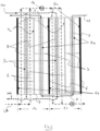
- the thermal water purification system 10 comprises first to fourth adjacent distilling units 1a, 1b, 1c and 1d which are consecutively flowed by the raw feed liquid to be concentrated.
- This raw feed liquid can be brackish water, seawater or industrial process wastewater for example.
- This raw feed liquid flows inside the system according to a specific flow circuit and flow direction illustrated in Figure 1 by two types of arrows.
- the first type of arrows corresponds to conduits, pipes or conducts for transporting the raw feed liquid L P from the fourth distilling unit 1d to the first distilling unit 1a.
- the raw feed liquid L P is thus preheated before flowing through a heat exchanger cavity, which is adapted to increase the temperature of the raw feed liquid L P till said raw feed liquid is partially boiling or close to its boiling point.
- the term "boiling raw feed liquid” and the reference L B will be used in replacement of the term "raw feed liquid” and the reference L P .
- Further heat exchanger elements may advantageously be provided to heat the boiling raw feed liquid L B .
- Such heat exchanger elements may consist in a plurality of heat exchanger tubes, through which is flowing a hot medium H M , such as hot water or steam.
- these heat exchanger tubes are partially integrated to one or more distilling units, thus optimizing the space occupied by the system and limiting the thermal losses during the transport of the fluid.
- the second type of arrows corresponds to conduits, pipes or conducts for transporting the boiling raw feed liquid L B from the first distilling unit 1a to the fourth distilling unit 1d. During this transport, the vapor phase of said boiling raw feed liquid L B is separated from the liquid phase thereof, said vapor phase being afterwards condensed against cold surfaces of the system and collected as a distillate liquid.
- Each distilling unit comprises one boiling liquid section 2 and one vapor section 3 adjacent thereto, said sections 2, 3 being separated by a liquid-tight and vapor-permeable membrane 7.
- This membrane 7 is configured to, on the one hand, prevent that the liquid phase of the boiling raw feed liquid L B flowing inside the boiling liquid section 2 to flow across to the vapor section 3, and, on the other hand, permit the evaporation of the boiling raw feed liquid L B on its surface 7a and allow the vapor phase of said boiling raw feed liquid L B to diffuse across into the vapor section 3 through its pores.
- the boiling liquid section 2 of the second distilling unit 1b is separated from the vapor section 3 of the first distilling unit 1a by a liquid-tight and vapor-tight separation plate 6, which may advantageously be provided with enhanced micro-structures such as micro-cavities or micro-projecting fins.
- This plate 6 is configured to prevent any fluid circulation between the two adjacent sections and permit the film wise condensation of the vapor phase of the boiling raw feed liquid L B flowing inside the vapor section 3 on the surface 6a that is oriented towards said vapor section. Furthermore, this plate 6, which is heated during the condensation process, has a hotter surface 6b that is oriented towards the boiling liquid section 2 of the second distilling unit 1b.
- This hotter surface 6b which is in contact with the boiling raw feed liquid L B flowing inside said boiling liquid section 2, may lead to flow boiling of said boiling raw feed liquid on surface 6b.
- a plurality of heat exchanger tubes 8 advantageously extend through said boiling liquid section 2. These heat exchanger tubes 8, which are flowed through by the hot medium H M , transfer thermal energy via their external surfaces 8a to the boiling raw feed liquid L B flowing inside the boiling liquid section 2 so that this boiling raw feed liquid L B boils in contact to said external surfaces 8a.
- the heat exchanger tubes 8 may advantageously be provided with internally and externally enhanced structures such as projecting fins arranged along their external surfaces 8a and internal ribs so as to enhance the thermal transfer occurring between the outside of said tubes and the inside thereof, thus enhancing the boiling of the boiling raw feed liquid L B against the external surfaces of the said heat exchanger tubes 8.
- the boiling raw feed liquid L B successively enters in the boiling liquid section 2 of the first distilling unit 1a through inlet ports 4, is partially vaporized via boiling and evaporation in said boiling liquid section 2, the vapor phase being diffused across the membrane 7 and the liquid phase exiting the boiling liquid section 2 through outlet ports 5. Thereafter, this liquid phase is channeled via conduits to the inlet ports 4 of the boiling liquid section 2 of the second distilling unit 1b.
- Throttle or flash valves 14 may advantageously be disposed along the conduits between the outlet ports 5 and the inlet ports 4 so as to reduce the pressure of the boiling raw feed liquid L B . This process may be repeated for the second distilling unit 1b, and, thereafter, for each successive distilling unit of the system 10.
- the system 10 comprises a plurality of preheating tubes 9 extending through the vapor sections 3 of the distilling units 1a-1d, said preheating tubes 9 being consecutively flowed through by the raw feed liquid before said raw feed liquid flows through the heat exchanger cavity and, thereafter, through the boiling liquid sections 2 of said distilling units 1a-1d.
- These preheating tubes 9 permit to preheat the raw feed liquid contained thereinside by using thermal energy transferred by the condensing vapor contained in the vapor sections 3 of the distilling units 1a-1d when said vapor condenses against external surfaces 9a of the preheating tubes 9.
- said tubes 9 may advantageously be provided with projecting fins arranged along their external surfaces 9a and internal rib structures.
- two vertically spaced-apart preheating tubes 9 are disposed in the bottom part of each vapor section 3 of the distilling units 1a-1d and two vertically spaced-apart internal boiling tubes 15 are disposed in the top part of each vapor section 3.
- These internal boiling tubes 15 are flowed through by the boiling raw feed liquid L B exiting from the outlet port 5 of the boiling liquid section 2 disposed upstream thereof relative to the flow direction of said boiling raw feed liquid L B and are in fluidic communication with the inlet port 4 of the boiling liquid section 2 disposed downstream relative to the flow direction of said boiling raw feed liquid L B , preferably via a throttle or flash valve.
- the vapor contained in the vapor sections 3 condenses against the peripheral external surfaces of both said preheating tubes 9 and said internal boiling tubes 15, which induces flow boiling inside said internal boiling tubes 15.
- the distillate liquid produced by the condensation of the vapor against the external surfaces of the internal boiling tubes 15 may advantageously have a higher temperature than the raw feed liquid L P flowing inside the preheating tubes 9, thus advantageously preheating said raw feed liquid L P .
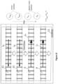
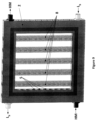
- the system 10 comprises eight consecutive distilling units 1a to 1h, said distilling units having substantially the same structure as the distilling units illustrated in Figure 1 .
- the heat exchanger tubes 8 extend only through the boiling liquid sections 2 of the first, second and third distilling units 1a, 1b and 1c.
- These heat exchanger tubes 8 are positioned downstream of a heat exchanger cavity 16 that comprises an insulation wall 17 and a heat transfer plate 18 horizontally spaced-apart therefrom, said heat transfer plate 18 being horizontally spaced-apart from the first separation plate 6' bordering the boiling liquid section 2 of the first distilling unit 1a.
- the insulation wall 17 and the heat transfer plate 18 define a first flow path for the preheated raw feed liquid L P exiting from the preheating tubes 9 of the first distilling unit 1a and the heat transfer plate 18 and the first separation plate 6' define a second flow path for the hot medium H M .
- the heat exchanger cavity 16 permits to heat the raw feed liquid L P flowing through the first flow path via the heat transfer plate 18.
- the system 10 illustrated in Figures 5 and 6 also comprises a preheating chamber 20 disposed upstream of the last distilling unit 1h relative to the flow direction of the raw feed liquid L P .
- This preheating chamber 20 comprises an insulation wall 17' and a heat transfer plate 18' horizontally spaced-apart therefrom, said heat transfer plate 18' bordering the vapor section 3 of the last distilling unit 1h.
- the insulation wall 17' and the heat transfer plate 18' define a first flow path for the raw feed liquid L P supplied from a raw liquid source 23.
- the preheating chamber 20 permits to heat the raw feed liquid L P via the heat transfer plate 18' due to the higher temperature T8 VAPOR of the vapor flowing inside the vapor section 3 of the last distilling unit 1h relative to the temperature T1 LP of the raw feed liquid L P of the first flow path.
- the temperature of the raw feed liquid L P increases to reach a final temperature T2 LP of said first flow path and before said raw feed liquid L P is channeled via conduits inside the preheating tubes 9 of the last distilling unit 1h.
- the system 10 may advantageously comprise a distillate conduit 12 in fluidic communication with the distillate discharge ports 11 of the distilling units 1a to 1h, said distillate conduit 12 channeling the distillate liquid towards a storage tank 13 via a plurality of constrictions 19, said constrictions 19 permitting to isolate the varying pressures occurring inside the distillate conduit 12. Indeed, from the first distilling unit 1a to the last distilling unit 1h, the pressure of the distillate liquid tends to decrease.
- the system 10 may also comprise a brine discharge 21 for collecting the concentrated boiling raw feed liquid L B exiting from the boiling liquid section 2 of the last distilling unit 1h and a non-condensable gas line 22 for collecting the non-condensable gasses exiting from the vapor sections 3 of the distilling units 1a to 1h.
- these operating steps can be adapted to any systems 10 having at least one distilling unit.
- a further step b') may consist in channeling the boiling raw feed liquid L B exiting from the outlet ports 5 of the boiling liquid section 2 of an upstream distilling unit into the vapor section 3 thereof through at least one internal boiling tube 15 before channeling said boiling raw feed liquid L B into the boiling liquid section 2 of a downstream distilling unit, said upstream and downstream distilling units being any two consecutive distilling units of the system.
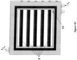
- FIGS 9 and 14 illustrate a boiling liquid section 2 comprising five vertically oriented and horizontally spaced-apart heat exchanger tubes 8, and several inlet ports 4 and outlet ports 5.
- the flow directions of hot medium H M and boiling raw feed liquid L B is shown in the same figures.
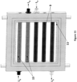
- Figures 10 and 15 illustrate a vapor section 3 comprising five horizontally oriented and vertically spaced-apart integrated preheating tubes 9, and a distillate discharge port 11.
- the flow direction of the raw feed liquid L P is shown in the same figures.
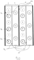
- Figure 11 illustrates a vapor section 3 comprising two horizontally oriented and vertically spaced-apart integrated internally boiling tubes 15 positioned at the top part of said vapor section and three horizontally oriented and vertically spaced-apart preheating tubes 9 positioned at the bottom part of said vapor section.
- Distillate discharge port 11, the raw feed liquid L P and the boiling raw feed liquid L B are also shown in the same figure.
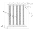
- Figure 12 illustrates a vapor section 3 comprising an array of internally boiling tubes 15 positioned at the top part of said vapor section, an array of preheating tubes 9 positioned at the bottom part of said vapor section and a distillate conduit 12 in fluidic communication with the distillate discharge ports 11 of said vapor section.
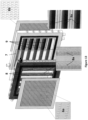
- Figure 13 illustrates a distilling unit comprising a micro-structured condensation surface 6a positioned in front of the boiling liquid section 2 illustrated in Figure 9 , and the vapor section 3 illustrated in Figure 10 positioned in front of condensation surface 6a with hotter surface 6b located on the opposite side of condensation surface 6a, said boiling liquid section 2 and said vapor section 3 being separated by a liquid-tight and vapor-permeable membrane 7.
- Flow boiling in the boiling liquid section 2 occurs on the external surface 8a of the heat-exchanger tubes 8 while vapor condensation in the vapor section 3 occurs on the external surface 9a of the preheating tubes 9 and condensation surface 6a.
- the thermal water purification system may include a plurality of consecutive modules, each module comprising several consecutive distilling units and being in a fluidic communication with an adjacent module via bifurcating flow configuration for the boiling raw feed liquid flowing inside the boiling liquid sections.
- the raw feed liquid flowing inside the preheating tubes can advantageously be in a bifurcating flow configuration.
- Example 1 8-effect MD system with vapor transmission lines but without feed preheating.
- Total membrane area (A m x 8-effect) 4.0 m 2
- First module thermal energy consumption for MD evaporation N x A m x H Lv / 3600s
- N x A m x 8-effect x ⁇ 32 L/hr
- Total output equivalent thermal energy Total distillate produced / 3600s x H LV ) 20.74 kW
- the first effect (steam riser) of the MD system can only consume 3.24 KW (10.8%) out of the total available thermal energy of 30 kW.
- the membrane area would have to be enlarged by 9.26 times to 4.63 m 2 /effect and a total system membrane area to 37.04 m 2 . No condensation losses in the transmission lines were assumed in the simulation.
- Example 2 8-effect MD system with vapor transmission lines and feed preheating.
- First module thermal energy consumption for MD evaporation N ⁇ A m ⁇ H LV / 3600
- First module thermal energy consumption for feed preheating V feed /60 ⁇ (T feed,final - T feed,in ) x Cp (4189 kJ/kg-K) / (8-effect x ⁇ )) 3.44 kW
- First module thermal energy consumption N ⁇ A R ⁇ H LV / 3600
- 668 kW Total membrane area required to implement MD and feed preheating,
- a R 1.03 m 2 Total distillate produced (N ⁇ A R ⁇ 8-effect ⁇ ⁇ ) 65.9 L/hr Total output equivalent thermal energy (Total distillate produced / 3600s ⁇ H LV ) 42.72 kW Total membrane area (A R ⁇ 8-effect) 8.24 m 2
- the first membrane module With feed preheating, the first membrane module is capable of consuming 6.68 kW (22.3%) of the total available thermal energy of 30 kW. However, the membrane area will have to be increased from 0.5 m 2 to 1.03 m 2 to produce enough vapor to accommodate feed preheating. The total system membrane area has now increased to 8.24 m 2 . No condensation losses in the transmission lines were assumed in the simulation. Due to the presence of vapor transmission lines, no performance enhancement in the MD process was taken into account.
- Example 3 Current invention as per the embodiment shown in Figure 5 with direct condensation and internal flow boiling tubes implemented into the first three modules. An equal distribution of thermal energy for flow boiling in the three modules is assumed for this simulation. In practical applications, the first effect can preferably be imposed a much higher thermal load to increase distillate production and thermal efficiency.
- Total membrane area (A m ⁇ 8-effect) 4.0 m 2
- First module thermal energy consumption for MD evaporation N ⁇ A m ⁇ H LV / 3600) 3.24 kW Thermal energy required for raw feed preheating / effect 3.44 kW Thermal energy consumption via tube boiling (First distilling effect) ⁇ (30 kW - 3.24 kW) / 3-effects 8.92 kW Thermal energy consumption via tube boiling (Second distilling effect) ⁇ (30 kW - 3.24 kW) / 3-effects 8.92 kW Thermal energy consumption via tube boiling (Third distilling effect) ⁇ (30 kW - 3.24 kW) / 3-effects 8.92 kW
- Estimated MD performance enhancement due to direct condensation and internal flow boiling 10 % Total distillate produced via MD N ⁇ A m ⁇ 8-effect ⁇ ⁇ ⁇ 1.1) 35.2 L/hr Total distillate produced via boiling in first effect ⁇ (8920/H LV ⁇ 3600) + ((8920 - 3440)
- the thermal energy required for MD is 3.24 kW while the remaining 27.76 kW being distributed into the heat exchanger boiling tubes in the first three (3) effects, i.e. 8.92 kW for boiling/effect.
- a total thermal load of 30 kW is consumed for vaporization of liquid to produce distillate and raw feed liquid preheating while maintaining the membrane area at 0.5 m 2 per effect, i.e. total system membrane area of 4.0 m 2 .
Landscapes
- Engineering & Computer Science (AREA)
- Water Supply & Treatment (AREA)
- Chemical & Material Sciences (AREA)
- Chemical Kinetics & Catalysis (AREA)
- Life Sciences & Earth Sciences (AREA)
- Hydrology & Water Resources (AREA)
- Environmental & Geological Engineering (AREA)
- Organic Chemistry (AREA)
- Vaporization, Distillation, Condensation, Sublimation, And Cold Traps (AREA)
Claims (11)
- Thermalwasserreinigungssystem (10) zum Produzieren einer Destillatflüssigkeit aus einer Rohzufuhrflüssigkeit (LP, LB), umfassend:- eine Vielzahl von Destillationseinheiten (1a-1h), die nacheinander durch die Rohzufuhrflüssigkeit (LP, LB) durchströmt wird, wobei die Vielzahl von Destillationseinheiten (1a-1h) eine erste Destillationseinheit (1a) und eine Vielzahl von aufeinanderfolgenden Destillationseinheiten (1b-1h) einschließt;wobei jede Destillationseinheit (1a-1h) einen Siedeflüssigkeitsabschnitt (2) und einen Dampfabschnitt (3) umfasst, der daran angrenzt;wobei der Siedeflüssigkeitsabschnitt (2) jeder Destillationseinheit (1a-1h) eine Vielzahl von Einlassöffnungen (4) und Auslassöffnungen (5) umfasst, durch die hindurch die Rohzufuhrflüssigkeit (LP, LB) jeweils eintritt und austritt;wobei beliebige zwei aufeinanderfolgende Destillationseinheiten (1a, 1b), beziehungsweise eine stromaufwärtige Destillationseinheit (1a) und eine stromabwärtige Destillationseinheit (1b), derart implementiert sind, dass der Siedeflüssigkeitsabschnitt (2) der stromabwärtigen Destillationseinheit (1b) von dem Dampfabschnitt (3) der stromaufwärtigen Destillationseinheit (1a) durch eine flüssigkeitsdichte und dampfdichte Trennplatte (6) und von dem Dampfabschnitt (3) der stromabwärtigen Destillationseinheit (1b) durch eine flüssigkeitsdichte und dampfdurchlässige Membran (7) getrennt ist;- einen Wärmetauscherhohlraum (16), der angepasst ist, um thermische Energie an die Rohzufuhrflüssigkeit (LP) zu übertragen, bevor die Rohzufuhrflüssigkeit in den Siedeflüssigkeitsabschnitt (2) der ersten Destillationseinheit (1a) eintritt;- eine Vielzahl von Wärmetauscherrohren (8), die sich durch den Siedeflüssigkeitsabschnitt (2) mindestens der ersten Destillationseinheit (1a) hindurch erstreckt, wobei die Wärmetauscherrohre (8) konfiguriert sind, um thermische Energie von einem heißen Medium (HM), das darin enthalten ist, zu der Rohzufuhrflüssigkeit (LB) zu übertragen, die dort hinausströmt, wodurch die Rohzufuhrflüssigkeit (LB) dazu gebracht wird, im Inneren des Siedeflüssigkeitsabschnitts (2) zu sieden;- eine Vielzahl von Vorheizrohren (9), die sich durch den Dampfabschnitt (3) jeder Destillationseinheit (1a-1h) hindurch erstreckt, wobei die Vorheizrohre (9) nacheinander durch die Rohzufuhrflüssigkeit (LP) durchströmt werden, bevor die Rohzufuhrflüssigkeit ins Innere der Siedeflüssigkeitsabschnitte (2) der Destillationseinheiten (1a-1h) strömt, und konfiguriert sind, um die Rohzufuhrflüssigkeit (LP), die darin enthalten ist, durch Verwenden von thermischer Energie zu erhitzen, die durch Dampf übertragen wird, der im Inneren der Dampfabschnitte (3) der Destillationseinheiten (1a-1h) enthalten ist, wenn der Dampf gegen Außenoberflächen (9a) der Vorheizrohre (9) kondensiert, wodurch eine Destillatflüssigkeit produziert wird, die aus dem Dampfabschnitt (3) jeder Destillationseinheit (1a-1h) durch eine Destillatabgabeöffnung (11) hindurch hinausströmt;- eine Destillatleitung (12) in Fluidverbindung mit jeder Destillatabgabeöffnung (11), wobei die Destillatleitung (12) einen Lagertank (13) mit der Destillatflüssigkeit versorgt,
wobei beliebige zwei aufeinanderfolgende Destillationseinheiten, beziehungsweise eine stromaufwärtige Destillationseinheit (1a) und eine stromabwärtige Destillationseinheit (1b), derart implementiert sind, dass die Auslassöffnungen (5) des Siedeflüssigkeitsabschnitts (2) der stromaufwärtigen Destillationseinheit (1a) in Fluidverbindung mit mindestens einem internen Siederohr (15) stehen, das sich durch den Dampfabschnitt (3) der stromaufwärtigen Destillationseinheit (1a) hindurch erstreckt und derart, dass die Einlassöffnungen (4) des Siedeflüssigkeitsabschnitts (2) der stromabwärtigen Destillationseinheit (1b) mit dem mindestens einen internen Siederohr (15) in Fluidverbindung stehen. - Thermalwasserreinigungssystem (10) nach Anspruch 1, wobei die erste Destillationseinheit (1a) von der Vielzahl von aufeinanderfolgenden Destillationseinheiten (1b-1h) des Thermalwasserreinigungssystems (10) stromaufwärts positioniert ist, was zu einer Abnahme der Temperatur (T(n)LB) der Rohzufuhrflüssigkeit (LB) führt, wenn sie von der ersten Destillationseinheit (1a) zu der Vielzahl von aufeinanderfolgenden Destillationseinheiten (1b-1h) strömt.
- Thermalwasserreinigungssystem (10) nach Anspruch 1 oder 2, wobei sich eine Vielzahl von Wärmetauscherrohren (8) ferner durch jeden Siedeflüssigkeitsabschnitt (2) von i weiteren aufeinanderfolgenden Destillationseinheiten (1b-1c) aus der Vielzahl von aufeinanderfolgenden Destillationseinheiten (1b-1h) hindurch erstreckt, wobei i eine ganze Zahl größer als 0 ist.
- Thermalwasserreinigungssystem (10) nach Anspruch 3, wobei i+1 weniger als 40% der Gesamtzahl der Destillationseinheiten des Thermalwasserreinigungssystems (10) darstellt.
- Thermalwasserreinigungssystem (10) nach irgendeinem der vorstehenden Ansprüche, wobei die Einlassöffnungen (4) des Siedeflüssigkeitsabschnitts (2) der stromabwärtigen Destillationseinheit (1b) über ein Drossel- oder ein Blitz-ventil (14) mit dem mindestens einen internen Siederohr (15) in Fluidverbindung stehen.
- Thermalwasserreinigungssystem (10) nach irgendeinem der vorstehenden Ansprüche, wobei die Trennplatte (6), die den Dampfabschnitt (3) einer stromaufwärtigen Destillationseinheit (1a) von dem Siedeflüssigkeitsabschnitt (2) einer stromabwärtigen Destillationseinheit (1b) trennt, konfiguriert ist, um die Rohzufuhrflüssigkeit (LB), die im Inneren des Siedeflüssigkeitsabschnitts (2) enthalten ist, durch Verwenden der thermischen Energie zu erhitzen, die durch den Dampf übertragen wird, der im Inneren des Dampfabschnitts (3) enthalten ist, wenn der Dampf gegen eine Kondensationsoberfläche (6a) der Trennplatte (6) kondensiert, wodurch die Rohzufuhrflüssigkeit (LB) dazu gebracht wird, im Inneren des Siedeflüssigkeitsabschnitts (2) zu sieden.
- Thermalwasserreinigungssystem (10) nach irgendeinem der vorstehenden Ansprüche, wobei die Vorheizrohre (9) mit vorstehenden Lamellen und Rippen versehen sind, die entlang ihres Umfangs angeordnet sind, wobei die Lamellen und Rippen die Wärmeübertragung zwischen der Außenseite jedes Vorheizrohrs (9) und der Innenseite davon verbessern.
- Verfahren zum Betreiben des Thermalwasserreinigungssystems (10) nach irgendeinem der vorstehenden Ansprüche, umfassend die folgenden Schritte:a) Leiten der Rohzufuhrflüssigkeit (LP), die anfänglich eine erste Temperatur (T1LP) aufweist, zu dem Siedeflüssigkeitsabschnitt (2) der ersten Destillationseinheit (1a) hin durch die Vielzahl von Vorheizrohren (9) hindurch, um die Temperatur (T(n)LP) der Rohzufuhrflüssigkeit (LP) von der ersten Temperatur (T1LP) auf eine zweite Temperatur (T10LP) zu erhöhen;b) Leiten der Rohzufuhrflüssigkeit (LP), dieanfänglich die zweite Temperatur (T10Lp) aufweist, zu dem Siedeflüssigkeitsabschnitt (2) der ersten Destillationseinheit (1a) hin durch den Wärmetauscherhohlraum (16) hindurch, um die Temperatur der Rohzufuhrflüssigkeit (LP) von der zweiten Temperatur (T10Lp) auf eine dritte Temperatur (T11Lp) unter Verwendung der thermischen Energie, die von dem heißen Medium (HM) übertragen wird, zu erhöhen;c) Leiten der Rohzufuhrflüssigkeit (LB), die anfänglich die dritte Temperatur (T11LP), oder eine Temperatur (T1LB) aufweist, die geringfügig niedriger als die dritte Temperatur (T11LP) ist, in die Siedeflüssigkeitsabschnitte (2) der ersten Destillationseinheit (1a) und, danach, die Vielzahl von aufeinanderfolgenden Destillationseinheiten (1b-1h);d) Erhitzen der Rohzufuhrflüssigkeit (LB), wobei sich die Vielzahl von Wärmetauscherrohren (8) durch den Siedeflüssigkeitsabschnitt (2) mindestens der ersten Destillationseinheit (1a) hindurch erstreckt, um die Rohzufuhrflüssigkeit (LB), die im Inneren des Siedeflüssigkeitsabschnitts (2) strömt, mit einer Abnahme der Temperatur (T(n)LB) der Rohzufuhrflüssigkeit (LB) in jedem Siedeflüssigkeitsabschnitt (2) aufgrund des Druckabfalls im Inneren jedes Siedeflüssigkeitsabschnitts von den Einlassöffnungen (4) davon zu den Auslassöffnungen (5) davon, zu sieden;e) Führen des Dampfes, der durch die Rohzufuhrflüssigkeit (LB) produziert wird, die in dem Siedeflüssigkeitsabschnitt (2) jeder Destillationseinheit (1a-1h) durch die flüssigkeitsdichte und dampfdurchlässige Membran (7) hindurch in den Dampfabschnitt (3), der daran angrenzt, siedet;f) Kondensieren des Dampfs in den Dampfabschnitt (3), um die Destillatflüssigkeit zu produzieren;g) Leiten der Destillatflüssigkeit in den Lagertank (13),
das Verfahren ferner umfassend, gleichzeitig zu Schritt c), den Schritt c), bestehend aus dem Leiten der Rohzufuhrflüssigkeit (LB), die aus den Auslassöffnungen (5) des Siedeflüssigkeitsabschnitts (2) einer stromaufwärtigen Destillationseinheit (1a) in den Dampfabschnitt (3) davon durch mindestens ein internes Siederohr (15) hindurch austritt, bevor die Rohzufuhrflüssigkeit (LB) in den Siedeflüssigkeitsabschnitt (2) einer stromabwärtigen Destillationseinheit (1b) geleitet wird, wobei die stromaufwärtigen und stromabwärtigen Destillationseinheiten (1a, 1b) beliebige zwei aufeinanderfolgende Destillationseinheiten des Thermalwasserreinigungssystems (10) sind. - Verfahren nach Anspruch 8, wobei, während Schritt c), die Rohzufuhrflüssigkeit (LB) siedet.
- Verfahren nach Anspruch 8 oder 9, wobei, während Schritt f), die Kondensation des Dampfes gegen Außenoberflächen (9a) der Vorheizrohre (9) gegen eine Kondensationsoberfläche (6a) jeder der Trennplatten (6) des Thermalwasserreinigungssystems (10) und gegen eine Außenoberfläche des mindestens einen internen Siederohrs (15) erfolgt.
- Verfahren nach irgendeinem der Ansprüche 8 bis 10, wobei Schritt d) ferner das Erhitzen der Rohzufuhrflüssigkeit (LB) mit einer Vielzahl von Wärmetauscherrohren (8) einschließt, die sich durch jeden Siedeflüssigkeitsabschnitt (2) von i weiteren aufeinanderfolgenden Destillationseinheiten (1b-1c) aus der Vielzahl von aufeinanderfolgenden Destillationseinheiten (1b-1h) hindurch erstreckt, wobei i eine ganze Zahl größer als 0 ist.
Applications Claiming Priority (2)
| Application Number | Priority Date | Filing Date | Title |
|---|---|---|---|
| PCT/IB2016/051471 WO2017158399A1 (en) | 2016-03-16 | 2016-03-16 | Thermal water purification system and method for operating said system |
| PCT/IB2017/051497 WO2017158526A1 (en) | 2016-03-16 | 2017-03-15 | Thermal water purification system and method for operating said system |
Publications (3)
| Publication Number | Publication Date |
|---|---|
| EP3429965A1 EP3429965A1 (de) | 2019-01-23 |
| EP3429965C0 EP3429965C0 (de) | 2024-07-24 |
| EP3429965B1 true EP3429965B1 (de) | 2024-07-24 |
Family
ID=55538307
Family Applications (1)
| Application Number | Title | Priority Date | Filing Date |
|---|---|---|---|
| EP17712552.3A Active EP3429965B1 (de) | 2016-03-16 | 2017-03-15 | System zur thermischen wasserreinigung und verfahren zum betrieb des besagten systems |
Country Status (5)
| Country | Link |
|---|---|
| US (1) | US10702830B2 (de) |
| EP (1) | EP3429965B1 (de) |
| CN (1) | CN108779005B (de) |
| ES (1) | ES2986292T3 (de) |
| WO (2) | WO2017158399A1 (de) |
Families Citing this family (4)
| Publication number | Priority date | Publication date | Assignee | Title |
|---|---|---|---|---|
| CN114288686A (zh) * | 2020-10-08 | 2022-04-08 | 罗氏分离系统印度(P)有限公司 | 一种用于蒸发和冷凝的系统和方法 |
| BE1029506B1 (fr) * | 2021-05-25 | 2023-01-23 | Ind Advanced Services Fze | Echangeur thermique avec extracteurs de vapeur |
| PE20241242A1 (es) * | 2021-10-08 | 2024-06-19 | Freshape Sa | Metodo y sistema de generacion de agua atmosferica |
| US20250058247A1 (en) * | 2023-08-14 | 2025-02-20 | Baryon Inc. | Liquid Separation System |
Citations (2)
| Publication number | Priority date | Publication date | Assignee | Title |
|---|---|---|---|---|
| EP1185356A1 (de) * | 1999-05-27 | 2002-03-13 | Nederlandse Organisatie Voor Toegepast-Natuurwetenschappelijk Onderzoek Tno | Verfahren zur reinigung von flüssigkeiten durch membrandestillation, insbesondere zur gewinnung von ensalztem wasser aus meerwasser oder brackwasser oder prozesswasser |
| EP2606953B1 (de) * | 2011-12-23 | 2015-03-18 | Aquaver B.V. | Membrandestillationssystem, Verfahren zum Starten eines solchen Systems und Verwendung davon |
Family Cites Families (11)
| Publication number | Priority date | Publication date | Assignee | Title |
|---|---|---|---|---|
| US72135A (en) | 1867-12-10 | Johni waivefield | ||
| US216916A (en) | 1879-06-24 | Improvement in round belting | ||
| US3361645A (en) | 1966-08-09 | 1968-01-02 | Bruce R. Bodell | Distillation of saline water using silicone rubber membrane |
| US4545862A (en) | 1981-03-17 | 1985-10-08 | W. L. Gore & Associates, Inc. | Desalination device and process |
| DE102004013647A1 (de) | 2004-03-19 | 2005-10-06 | Wolfgang Heinzl | Verfahren und Vorrichtung zur Destillation von Lösungen |
| EP1925355A1 (de) * | 2006-10-31 | 2008-05-28 | Nederlandse Organisatie voor toegepast- natuurwetenschappelijk onderzoek TNO | Membrandestillationsverfahren zur Reinigung einer Flüssigkeit |
| DE102009020179A1 (de) | 2009-05-06 | 2010-11-11 | Wolfgang Heinzl | Membrandestillationsvorrichtung |
| DE102011108909B4 (de) | 2011-07-29 | 2017-08-31 | Major Bravo Limited | Membrandestillationsvorrichtung |
| GB2504503A (en) | 2012-07-31 | 2014-02-05 | Ibm | Desalination system |
| NL2010576C2 (en) * | 2013-04-05 | 2014-10-08 | Aquaver B V | A system of membrane distillation and use therof. |
| EP2906331B8 (de) * | 2012-10-11 | 2017-08-02 | Major Bravo Limited | Membrandestillationssystem und verfahren zum starten solch eines systems |
-
2016
- 2016-03-16 WO PCT/IB2016/051471 patent/WO2017158399A1/en not_active Ceased
-
2017
- 2017-03-15 WO PCT/IB2017/051497 patent/WO2017158526A1/en not_active Ceased
- 2017-03-15 EP EP17712552.3A patent/EP3429965B1/de active Active
- 2017-03-15 ES ES17712552T patent/ES2986292T3/es active Active
- 2017-03-15 CN CN201780018021.8A patent/CN108779005B/zh active Active
- 2017-03-15 US US16/083,731 patent/US10702830B2/en active Active
Patent Citations (2)
| Publication number | Priority date | Publication date | Assignee | Title |
|---|---|---|---|---|
| EP1185356A1 (de) * | 1999-05-27 | 2002-03-13 | Nederlandse Organisatie Voor Toegepast-Natuurwetenschappelijk Onderzoek Tno | Verfahren zur reinigung von flüssigkeiten durch membrandestillation, insbesondere zur gewinnung von ensalztem wasser aus meerwasser oder brackwasser oder prozesswasser |
| EP2606953B1 (de) * | 2011-12-23 | 2015-03-18 | Aquaver B.V. | Membrandestillationssystem, Verfahren zum Starten eines solchen Systems und Verwendung davon |
Also Published As
| Publication number | Publication date |
|---|---|
| EP3429965A1 (de) | 2019-01-23 |
| EP3429965C0 (de) | 2024-07-24 |
| WO2017158399A1 (en) | 2017-09-21 |
| US20190083935A1 (en) | 2019-03-21 |
| CN108779005A (zh) | 2018-11-09 |
| WO2017158526A1 (en) | 2017-09-21 |
| CN108779005B (zh) | 2021-10-01 |
| ES2986292T3 (es) | 2024-11-11 |
| US10702830B2 (en) | 2020-07-07 |
Similar Documents
| Publication | Publication Date | Title |
|---|---|---|
| US9630862B2 (en) | Desalination system and method for desalination | |
| CN101325992B (zh) | 膜蒸馏方法和膜蒸馏装置 | |
| US6716355B1 (en) | Method for the purification of a liquid by membrane distillation, in particular for the production of desalinated water from seawater or brackish water or process water | |
| EP3429965B1 (de) | System zur thermischen wasserreinigung und verfahren zum betrieb des besagten systems | |
| KR101186167B1 (ko) | 태양열 다단 및 다중효용 증발식 해수 담수화장치 | |
| SI2939981T1 (en) | Sea water desalination apparatus and process using solar energy for continuous heat supply | |
| WO2016103029A1 (en) | Vacuumed gap membrane distillation (vagmed) module, multi-stage vagmed systems, and vagmed processes | |
| CN104190259A (zh) | 减压多效膜蒸馏方法及其装置 | |
| JP6289413B2 (ja) | 発電・海水淡水化方法およびシステム | |
| CN100548424C (zh) | 受多级闪蒸馏出物驱动的脱盐方法和装置 | |
| JP2014188399A (ja) | 海水の淡水化システム及び方法 | |
| CN103316588A (zh) | 多效膜蒸馏装置与方法 | |
| WO2001072638A1 (fr) | Dispositif de dessalement | |
| US11465068B2 (en) | Multi-stage flash (MSF) reversal system and method | |
| CN203959977U (zh) | 石油工业废水回收处理系统 | |
| CN101564648A (zh) | 一种化工产品浓缩分离装置与方法 | |
| Ali | Novel structures of direct contact membrane distillation for brackish water desalination using distributed feed flow | |
| CN1791556B (zh) | 水处理的方法和设备 | |
| EP2903723B1 (de) | Membrandestillationssystem und -verfahren | |
| EP3881917A1 (de) | Destillationmodul und multi-stufe distillationsvorrichtung | |
| CN212403520U (zh) | 一种真空法海水淡化系统 | |
| JP7540804B1 (ja) | 海水淡水化・塩分製造プラント | |
| JPH1110147A (ja) | 造水装置 | |
| JP4863781B2 (ja) | 多重効用造水装置 | |
| Sommariva | Thermal desalination processes and economics |
Legal Events
| Date | Code | Title | Description |
|---|---|---|---|
| STAA | Information on the status of an ep patent application or granted ep patent |
Free format text: STATUS: UNKNOWN |
|
| STAA | Information on the status of an ep patent application or granted ep patent |
Free format text: STATUS: THE INTERNATIONAL PUBLICATION HAS BEEN MADE |
|
| PUAI | Public reference made under article 153(3) epc to a published international application that has entered the european phase |
Free format text: ORIGINAL CODE: 0009012 |
|
| STAA | Information on the status of an ep patent application or granted ep patent |
Free format text: STATUS: REQUEST FOR EXAMINATION WAS MADE |
|
| 17P | Request for examination filed |
Effective date: 20180924 |
|
| AK | Designated contracting states |
Kind code of ref document: A1 Designated state(s): AL AT BE BG CH CY CZ DE DK EE ES FI FR GB GR HR HU IE IS IT LI LT LU LV MC MK MT NL NO PL PT RO RS SE SI SK SM TR |
|
| AX | Request for extension of the european patent |
Extension state: BA ME |
|
| TPAC | Observations filed by third parties |
Free format text: ORIGINAL CODE: EPIDOSNTIPA |
|
| DAV | Request for validation of the european patent (deleted) | ||
| DAX | Request for extension of the european patent (deleted) | ||
| STAA | Information on the status of an ep patent application or granted ep patent |
Free format text: STATUS: EXAMINATION IS IN PROGRESS |
|
| 17Q | First examination report despatched |
Effective date: 20211001 |
|
| RAP3 | Party data changed (applicant data changed or rights of an application transferred) |
Owner name: ECOLE POLYTECHNIQUE FEDERALE DE LAUSANNE (EPFL) |
|
| GRAP | Despatch of communication of intention to grant a patent |
Free format text: ORIGINAL CODE: EPIDOSNIGR1 |
|
| STAA | Information on the status of an ep patent application or granted ep patent |
Free format text: STATUS: GRANT OF PATENT IS INTENDED |
|
| INTG | Intention to grant announced |
Effective date: 20240125 |
|
| GRAS | Grant fee paid |
Free format text: ORIGINAL CODE: EPIDOSNIGR3 |
|
| GRAA | (expected) grant |
Free format text: ORIGINAL CODE: 0009210 |
|
| STAA | Information on the status of an ep patent application or granted ep patent |
Free format text: STATUS: THE PATENT HAS BEEN GRANTED |
|
| AK | Designated contracting states |
Kind code of ref document: B1 Designated state(s): AL AT BE BG CH CY CZ DE DK EE ES FI FR GB GR HR HU IE IS IT LI LT LU LV MC MK MT NL NO PL PT RO RS SE SI SK SM TR |
|
| REG | Reference to a national code |
Ref country code: GB Ref legal event code: FG4D |
|
| REG | Reference to a national code |
Ref country code: CH Ref legal event code: EP |
|
| REG | Reference to a national code |
Ref country code: IE Ref legal event code: FG4D Ref country code: DE Ref legal event code: R096 Ref document number: 602017083494 Country of ref document: DE |
|
| U01 | Request for unitary effect filed |
Effective date: 20240724 |
|
| U07 | Unitary effect registered |
Designated state(s): AT BE BG DE DK EE FI FR IT LT LU LV MT NL PT SE SI Effective date: 20240807 |
|
| REG | Reference to a national code |
Ref country code: ES Ref legal event code: FG2A Ref document number: 2986292 Country of ref document: ES Kind code of ref document: T3 Effective date: 20241111 |
|
| PG25 | Lapsed in a contracting state [announced via postgrant information from national office to epo] |
Ref country code: NO Free format text: LAPSE BECAUSE OF FAILURE TO SUBMIT A TRANSLATION OF THE DESCRIPTION OR TO PAY THE FEE WITHIN THE PRESCRIBED TIME-LIMIT Effective date: 20241024 |
|
| PG25 | Lapsed in a contracting state [announced via postgrant information from national office to epo] |
Ref country code: GR Free format text: LAPSE BECAUSE OF FAILURE TO SUBMIT A TRANSLATION OF THE DESCRIPTION OR TO PAY THE FEE WITHIN THE PRESCRIBED TIME-LIMIT Effective date: 20241025 Ref country code: PL Free format text: LAPSE BECAUSE OF FAILURE TO SUBMIT A TRANSLATION OF THE DESCRIPTION OR TO PAY THE FEE WITHIN THE PRESCRIBED TIME-LIMIT Effective date: 20240724 |
|
| PG25 | Lapsed in a contracting state [announced via postgrant information from national office to epo] |
Ref country code: IS Free format text: LAPSE BECAUSE OF FAILURE TO SUBMIT A TRANSLATION OF THE DESCRIPTION OR TO PAY THE FEE WITHIN THE PRESCRIBED TIME-LIMIT Effective date: 20241124 |
|
| PG25 | Lapsed in a contracting state [announced via postgrant information from national office to epo] |
Ref country code: HR Free format text: LAPSE BECAUSE OF FAILURE TO SUBMIT A TRANSLATION OF THE DESCRIPTION OR TO PAY THE FEE WITHIN THE PRESCRIBED TIME-LIMIT Effective date: 20240724 |
|
| PG25 | Lapsed in a contracting state [announced via postgrant information from national office to epo] |
Ref country code: RS Free format text: LAPSE BECAUSE OF FAILURE TO SUBMIT A TRANSLATION OF THE DESCRIPTION OR TO PAY THE FEE WITHIN THE PRESCRIBED TIME-LIMIT Effective date: 20241024 |
|
| PG25 | Lapsed in a contracting state [announced via postgrant information from national office to epo] |
Ref country code: RS Free format text: LAPSE BECAUSE OF FAILURE TO SUBMIT A TRANSLATION OF THE DESCRIPTION OR TO PAY THE FEE WITHIN THE PRESCRIBED TIME-LIMIT Effective date: 20241024 Ref country code: PL Free format text: LAPSE BECAUSE OF FAILURE TO SUBMIT A TRANSLATION OF THE DESCRIPTION OR TO PAY THE FEE WITHIN THE PRESCRIBED TIME-LIMIT Effective date: 20240724 Ref country code: NO Free format text: LAPSE BECAUSE OF FAILURE TO SUBMIT A TRANSLATION OF THE DESCRIPTION OR TO PAY THE FEE WITHIN THE PRESCRIBED TIME-LIMIT Effective date: 20241024 Ref country code: IS Free format text: LAPSE BECAUSE OF FAILURE TO SUBMIT A TRANSLATION OF THE DESCRIPTION OR TO PAY THE FEE WITHIN THE PRESCRIBED TIME-LIMIT Effective date: 20241124 Ref country code: HR Free format text: LAPSE BECAUSE OF FAILURE TO SUBMIT A TRANSLATION OF THE DESCRIPTION OR TO PAY THE FEE WITHIN THE PRESCRIBED TIME-LIMIT Effective date: 20240724 Ref country code: GR Free format text: LAPSE BECAUSE OF FAILURE TO SUBMIT A TRANSLATION OF THE DESCRIPTION OR TO PAY THE FEE WITHIN THE PRESCRIBED TIME-LIMIT Effective date: 20241025 |
|
| PG25 | Lapsed in a contracting state [announced via postgrant information from national office to epo] |
Ref country code: RO Free format text: LAPSE BECAUSE OF FAILURE TO SUBMIT A TRANSLATION OF THE DESCRIPTION OR TO PAY THE FEE WITHIN THE PRESCRIBED TIME-LIMIT Effective date: 20240724 Ref country code: SM Free format text: LAPSE BECAUSE OF FAILURE TO SUBMIT A TRANSLATION OF THE DESCRIPTION OR TO PAY THE FEE WITHIN THE PRESCRIBED TIME-LIMIT Effective date: 20240724 |
|
| PG25 | Lapsed in a contracting state [announced via postgrant information from national office to epo] |
Ref country code: CZ Free format text: LAPSE BECAUSE OF FAILURE TO SUBMIT A TRANSLATION OF THE DESCRIPTION OR TO PAY THE FEE WITHIN THE PRESCRIBED TIME-LIMIT Effective date: 20240724 |
|
| PG25 | Lapsed in a contracting state [announced via postgrant information from national office to epo] |
Ref country code: SK Free format text: LAPSE BECAUSE OF FAILURE TO SUBMIT A TRANSLATION OF THE DESCRIPTION OR TO PAY THE FEE WITHIN THE PRESCRIBED TIME-LIMIT Effective date: 20240724 |
|
| PGFP | Annual fee paid to national office [announced via postgrant information from national office to epo] |
Ref country code: GB Payment date: 20250328 Year of fee payment: 9 |
|
| U20 | Renewal fee for the european patent with unitary effect paid |
Year of fee payment: 9 Effective date: 20250324 |
|
| PLBE | No opposition filed within time limit |
Free format text: ORIGINAL CODE: 0009261 |
|
| STAA | Information on the status of an ep patent application or granted ep patent |
Free format text: STATUS: NO OPPOSITION FILED WITHIN TIME LIMIT |
|
| 26N | No opposition filed |
Effective date: 20250425 |
|
| PGFP | Annual fee paid to national office [announced via postgrant information from national office to epo] |
Ref country code: ES Payment date: 20250429 Year of fee payment: 9 |
|
| PGFP | Annual fee paid to national office [announced via postgrant information from national office to epo] |
Ref country code: CH Payment date: 20250401 Year of fee payment: 9 |
|
| PG25 | Lapsed in a contracting state [announced via postgrant information from national office to epo] |
Ref country code: MC Free format text: LAPSE BECAUSE OF FAILURE TO SUBMIT A TRANSLATION OF THE DESCRIPTION OR TO PAY THE FEE WITHIN THE PRESCRIBED TIME-LIMIT Effective date: 20240724 |