EP3429096B1 - Zones de couverture flexibles pour signaux de liaison aller dans un système de communication satellite à faisceau étroit - Google Patents
Zones de couverture flexibles pour signaux de liaison aller dans un système de communication satellite à faisceau étroit Download PDFInfo
- Publication number
- EP3429096B1 EP3429096B1 EP18175861.6A EP18175861A EP3429096B1 EP 3429096 B1 EP3429096 B1 EP 3429096B1 EP 18175861 A EP18175861 A EP 18175861A EP 3429096 B1 EP3429096 B1 EP 3429096B1
- Authority
- EP
- European Patent Office
- Prior art keywords
- forward link
- link signal
- spot beam
- spot
- multiple versions
- Prior art date
- Legal status (The legal status is an assumption and is not a legal conclusion. Google has not performed a legal analysis and makes no representation as to the accuracy of the status listed.)
- Active
Links
- 238000004891 communication Methods 0.000 title claims description 4
- 238000000034 method Methods 0.000 claims description 25
- 230000005540 biological transmission Effects 0.000 claims description 9
- 239000011159 matrix material Substances 0.000 description 30
- 238000010586 diagram Methods 0.000 description 14
- 239000000969 carrier Substances 0.000 description 10
- 230000010363 phase shift Effects 0.000 description 8
- 230000002238 attenuated effect Effects 0.000 description 7
- 238000013459 approach Methods 0.000 description 6
- 230000003111 delayed effect Effects 0.000 description 6
- 230000008569 process Effects 0.000 description 6
- 230000008901 benefit Effects 0.000 description 4
- 238000012986 modification Methods 0.000 description 4
- 230000004048 modification Effects 0.000 description 4
- 238000013461 design Methods 0.000 description 3
- 238000001228 spectrum Methods 0.000 description 3
- 230000003044 adaptive effect Effects 0.000 description 2
- 238000010276 construction Methods 0.000 description 2
- 230000001934 delay Effects 0.000 description 2
- 238000012938 design process Methods 0.000 description 2
- 230000009467 reduction Effects 0.000 description 2
- 230000003321 amplification Effects 0.000 description 1
- 230000003466 anti-cipated effect Effects 0.000 description 1
- 230000008859 change Effects 0.000 description 1
- 238000006243 chemical reaction Methods 0.000 description 1
- 238000007796 conventional method Methods 0.000 description 1
- 230000001419 dependent effect Effects 0.000 description 1
- 238000011161 development Methods 0.000 description 1
- 230000000694 effects Effects 0.000 description 1
- 239000000835 fiber Substances 0.000 description 1
- 230000006870 function Effects 0.000 description 1
- 238000003780 insertion Methods 0.000 description 1
- 230000037431 insertion Effects 0.000 description 1
- 238000002955 isolation Methods 0.000 description 1
- 230000008450 motivation Effects 0.000 description 1
- 238000003199 nucleic acid amplification method Methods 0.000 description 1
- 230000003287 optical effect Effects 0.000 description 1
- 230000037361 pathway Effects 0.000 description 1
- 230000010287 polarization Effects 0.000 description 1
- 238000012545 processing Methods 0.000 description 1
- 230000019491 signal transduction Effects 0.000 description 1
- 238000012360 testing method Methods 0.000 description 1
Images


Classifications
-
- H—ELECTRICITY
- H04—ELECTRIC COMMUNICATION TECHNIQUE
- H04B—TRANSMISSION
- H04B7/00—Radio transmission systems, i.e. using radiation field
- H04B7/14—Relay systems
- H04B7/15—Active relay systems
- H04B7/185—Space-based or airborne stations; Stations for satellite systems
- H04B7/1851—Systems using a satellite or space-based relay
- H04B7/18515—Transmission equipment in satellites or space-based relays
-
- H—ELECTRICITY
- H04—ELECTRIC COMMUNICATION TECHNIQUE
- H04B—TRANSMISSION
- H04B7/00—Radio transmission systems, i.e. using radiation field
- H04B7/14—Relay systems
- H04B7/15—Active relay systems
- H04B7/204—Multiple access
- H04B7/2041—Spot beam multiple access
-
- Y—GENERAL TAGGING OF NEW TECHNOLOGICAL DEVELOPMENTS; GENERAL TAGGING OF CROSS-SECTIONAL TECHNOLOGIES SPANNING OVER SEVERAL SECTIONS OF THE IPC; TECHNICAL SUBJECTS COVERED BY FORMER USPC CROSS-REFERENCE ART COLLECTIONS [XRACs] AND DIGESTS
- Y02—TECHNOLOGIES OR APPLICATIONS FOR MITIGATION OR ADAPTATION AGAINST CLIMATE CHANGE
- Y02D—CLIMATE CHANGE MITIGATION TECHNOLOGIES IN INFORMATION AND COMMUNICATION TECHNOLOGIES [ICT], I.E. INFORMATION AND COMMUNICATION TECHNOLOGIES AIMING AT THE REDUCTION OF THEIR OWN ENERGY USE
- Y02D30/00—Reducing energy consumption in communication networks
- Y02D30/70—Reducing energy consumption in communication networks in wireless communication networks
Definitions
- the present invention relates generally to satellite communications systems. More particularly, the present invention relates to methods and apparatuses for providing dynamic power distribution for forward link signals at a spot beam satellite.
- Spot beam satellites are effective for the transmission and reception of unicast and multicast data.
- many smaller spot beams are used to provide coverage for a larger area that is defined by the union of the areas covered by each of the smaller spot beams.
- FIGS. 1A-1C show how a number of spot beams, such as individual spot beam 102, provide satellite coverage over a large coverage area 104.
- FIG. 2 is a simplified diagram of a forward link of a typical bent pipe spot beam satellite system using a hub-spoke architecture.
- the depicted hardware connects one user beam 224 (or spot beam) to a gateway (GW) terminal 207 in a GW beam 208.
- the GW terminal 207 transmits data through a satellite 206 down to a plurality of user terminals (UT's) 226 in the user beam 224.
- the satellite 206 in this example is simplified but shows key elements of one forward link signal pathway including a receive (Rx) antenna 212, a low noise amplifier (LNA) 214, a frequency converter 216, a high power amplifier (HPA) 218, and a transmit (Tx) antenna 220.
- Rx receive
- LNA low noise amplifier
- HPA high power amplifier
- Tx transmit
- Many UT's 226 can operate in the same user beam 224 and receive data from a single GW transmission 210 via multiplexing of the data into a single aggregated downlink signal 222 (e.g., time division multiplexing (TDM), frequency divisional multiplexing (FDM), and the like).
- TDM time division multiplexing
- FDM frequency divisional multiplexing
- each UT only processes the data in the stream that is addressed to itself.
- a typical satellite 206 can have a number of these sets of pathway hardware connecting a number of GW's to a number of user beams.
- a MPA can include a hybrid matrix (HM) 332, HPA's 318a, 318b, 318N, and an inverse hybrid matrix 334.
- HM hybrid matrix
- HPA's 318a, 318b, 318N HPA's 318a, 318b, 318N
- inverse hybrid matrix 334 HPA's 318a, 318b, 318 N in parallel.
- an input signal s(t) is applied to one input port, and all other inputs are terminated (no input signal).
- the output signal y(t) is present on the first output port, and all other ports are terminated with essentially no signal present.
- the motivation is to make a higher power HPA by combining N HPA's.
- the MPA can be used to increase transmit power to a single user beam.
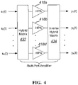
- FIG. 4 shows a HM 432, HPA's 418a, 418b, 418 N, and an inverse hybrid matrix 434.
- the N input signals s 1 (t)..s N (t) are different data streams with the content of each stream targeted for different sets of UT's in different spot beams.
- the input signals s 1 (t)..s n (t) may originate, for example, from different GW terminals.
- the output signals y 1 (t)..y N (t) are amplified versions of the input signals, Different data content is provided to each of the N beams.
- the MPA can be used to share total transmit power amongst the distinct user beams.
- a single user beam 224 typically covers a small subset of a desired coverage area.
- Many user beams are employed in a manner similar to that depicted in FIG. 1 to provide service to a larger coverage area.
- Each of the user beams is serviced by a GW, and a number of user beams may be serviced by the same GW by use of different frequencies and/or polarizations.
- the total coverage area is the union of the areas covered by the individual user spot beams. This coverage area is the region where satellite service can be offered to customers. This coverage area is fixed and is selected during a satellite design process.
- Satellite procurement, design, construction, launch, and test is a lengthy process. This process typically takes up to four years or more.
- the coverage area must be specified very early on in this process. In many instances, the desired coverage area is not well known at these early stages of satellite design. An educated guess must be made as to where the best coverage areas might be. If one chooses incorrectly, a coverage area may be selected that has few potential customers. This is clearly an undesirable consequence.
- Satellites typically have an operational lifetime of 15 years or more.
- target services areas can change dramatically. This can occur due to the development of ground infrastructure (e.g., wireless and fiber network build outs), re-purposing of the satellite, movement of the satellite to a different orbit slot, and the like.
- the satellite spot beams, however, and thus the coverage areas, are fixed in location and typically cannot be modified despite these changes.
- offered load at different spot beams can vary dramatically over short time periods.
- a satellite system that covers the continental United States may experience busy hours on the East Coast that correspond to non-busy hours on the West Coast.
- US 6,442,148 B1 discloses a satellite subsystem for a satellite that employs a reconfigurable communications payload and active array antennas.
- Some embodiments of the present invention provide methods and apparatuses for providing flexible coverage areas and flexible capacity for forward links of a spot beam satellite. This can allow coverage areas to be defined later in the design process and allow coverage areas and capacity to be changed during the operational lifetime of the satellite.
- a method for distributing transmit power of a forward link signal at a spot beam satellite includes receiving a forward link signal from a gateway, generating multiple versions of the forward link signal, and de-correlating the multiple versions of the forward link signal. The method also includes selectively attenuating at least one of the multiple versions of the forward link signal and, after the step of selectively attenuating, amplifying the multiple versions of the forward link signal using a multi-port amplifier to generate multiple amplified signals. The method also includes transmitting the multiple amplified signals to multiple spot beams.
- a method for distributing transmit power of a forward link signal at a spot beam satellite includes receiving a forward link signal from a gateway, generating multiple versions of the forward link signal, and delaying at least one of the multiple versions of the forward link signal.
- the method also includes selectively attenuating at least one of the multiple versions of the forward link signal and, after the step of selectively attenuating, amplifying the multiple versions of the forward link signal using a multi-port amplifier to generate one or more amplified signals.
- the step of selectively attenuating may use attenuation values received from a source remote from the spot beam satellite after the spot beam satellite has been deployed in space.
- the method also includes transmitting the one or more amplified signals as one or more spot beams.
- a spot beam satellite configured to allow dynamic distribution of transmit power across forward link signals includes an antenna configured to receive a forward link signal from a gateway, and a 1-to-N splitter configured to generate multiple versions of the forward link signal received from the gateway.
- the spot beam satellite also includes one or more de-correlation elements configured to de-correlate the multiple versions of the forward link signal received from the gateway, and one or more attenuators configured to attenuate the multiple versions of the forward link signal received from the gateway.
- the spot beam satellite also includes a multi-port amplifier configured to amplify the multiple versions of the forward link signal received from the gateway to generate one or more amplified signals, and a transmitter configured to transmit the one or more amplified signals as one or more spot beams.
- delayed and attenuated versions of a signal are input to a multi-port amplifier. This allows transmit power to be distributed across different spot beams.
- the versions of the signal may be attenuated using programmable attenuators. This allows the transmit power to be dynamically re-distributed across the different spot beams.
- programmable attenuators This allows the transmit power to be dynamically re-distributed across the different spot beams.
- one or more of these benefits may exist.
- Some embodiments of the present invention provide methods and apparatuses for providing flexible coverage areas and flexible capacity for forward links of a spot beam satellite.
- a multi-port amplifier uses delayed and attenuated versions of a signal to dynamically distribute transmit power between user beams. This allows transmit power to be distributed amongst the user beams in any desired proportion.
- FIG. 5 is a simplified diagram of a forward link of a spot beam satellite in accordance with an embodiment of the invention.
- the satellite 506 in this diagram is simplified but shows the components relevant to the description.
- the N user beams 524a, ... 524N may use the same spectrum.
- the N user beams 524a, ... 524N can all be formed via the same satellite Tx antenna using different feeds, or they can be formed by different Tx antennas 520a, ... 520N.
- the N user beams 524a, ... 524N form a beam group.
- the location of each of the beams in the beam group may be selected and fixed during the design phase of the satellite.
- the forward link signal 510 originates from the GW terminal and is received by the satellite 506 through the Rx antenna 512. After conventional low noise amplification using LNA 514 and frequency conversion using frequency converter 516, the signal s(t) is split into N copies via a 1:N power divider 526.
- delay elements 5281, ... 528N are used to de-correlate the N inputs to the hybrid matrix (HM) 532.
- Each output of the power divider 526 is delayed by an amount D n using delay elements 528a, ... 528N and attenuated by an amount A n using the programmable attenuators 530a, ... 530N.
- one or more of the programmable attenuators 530a, 530N may be disposed before the delay elements 528a, ... 528N such that outputs of the power divider 526 are attenuated by an amount A n before being delayed by an amount D n .
- the values for the programmable attenuators 530a, ... 530N can be uplinked to the satellite 506 via a command link that originates from a remote location (e.g., a control station).
- a command receiver and control processor (not shown) on the satellite 506 can receive these attenuation values and set the programmable attenuators 530a, ... 530N accordingly.
- D 1 need not be present (can be a zero delay).
- the elements D 2 through D N provide different values to de-correlate the N inputs to the HM 532. Other techniques can be used to de-correlate the signals in accordance with embodiments of the invention.
- the HM 532 may distribute a signal from an input port to each of its output ports that is equal in level but with differing phase shift.
- the signal at the output port of the HM 532 has contributions from the input signal on each input port.
- the input delays D 1 ...D N may be selected to provide a de-correlated input condition.
- the input power to each of the HPA's 518a, ... 518N will be equal to each other regardless of the selected attenuator values A 1 ...A N .
- the HPA's 518a, ... 518N provide matched gain and phase shift for each of the N signals out of the hybrid matrix.
- Inverse hybrid matrix 534 may be similar to the HM 532 in that it may distribute a signal from an input port to each of the output ports that is equal in level but with differing phase shift.
- the phase shifts through the inverse hybrid matrix 534 are set so as to undo the scrambling of the signals performed by the HM 532.
- Embodiments of the present invention are distinguishable from the conventional use of MPA's illustrated in FIGS. 3-4 .
- the signals are de-correlated through specific processing (e.g., the delay elements).
- embodiments of the present invention provide the same data content to all N MPA inputs at adjustable levels.
- the MPA inputs may be considered to be automatically de-correlated since only one input port has a signal applied.
- the inputs s 1 (t)..s N (t) may be considered to be automatically de-correlated since all N signals consist of different data.
- the satellite shown in FIG. 5 may be used in accordance with an embodiment of the invention.
- the uplink signal 510 at the input to the power divider 526 is denoted s(t)
- the output signals from the inverse hybrid matrix 534 will be an amplified and delayed version of s(t). However, each output signal will be attenuated by a level A n . If g is the power gain of each HPA 518a, ...
- the attenuator settings A 1 ...A N can be used to distribute the signal power amongst the user beams 524a, ... 524N in any proportion desired.
- the flexibility within the beam group comes from the programmable attenuator settings A 1 through A N , which can be used to tailor the EIRP distribution across the user beams 524a, ... 524N in any manner desired. Furthermore, the EIRP distribution can be changed at any time during the lifetime of the satellite. The ability to customize the EIRP distribution across the user beams 524a, ... 524N allows the forward link capacity to be distributed in any proportion desired, for example, by short messages from a ground-based controller.
- the uplink signal from the GW may be a single carrier that occupies the entire spectrum of the beam.
- FIG. 6 shows a simplified diagram of an uplink signal 610 that includes a single time division multiplexed (TDM) carrier.
- the TDM carrier is transmitted by a GW 607 to a satellite 606.
- the satellite receives the TDM carrier and downlinks the carrier in signal 622a to user beam 624a and in signal 622N to user beam 624N.
- the UT's in each beam may process only the portion of the carrier that is addressed to them.
- the carrier downlinked to user beam 624N is illustrated as being taller than the carrier downlinked to signal 624a to represent different levels of transmit power.
- the transmit power may be distributed between the beams 624a, ... 624N as explained above with regard to FIG. 5 .
- all of the data is downlinked to each of the user beams 624a, ... 624N even though only a subset of the data is addressed to UT's in any given beam.
- the uplink signal from the GW can include multiple carriers that each occupy portions of the spectrum.
- FIG. 7 shows a simplified diagram of an uplink signal 710 transmitted by a gateway 707.
- the uplink signal includes multiple frequency division multiplexed (FDM) carriers that are received by satellite 706 and downlinked to a plurality of user beams 724a, ... 724N.
- the FDM carriers are shown as having different widths and different heights representing different bandwidths and different levels of power, respectively.
- Each carrier may be associated with a particular user beam and contain data addressed only to UT's in that beam. In this example, there may be more than one carrier associated with each beam.
- each UT may process only the data in the carrier that is addressed to itself.
- the FDM carriers may be downlinked in signals 722a, ... 722N to user beams 724a, ... 724N respectively. Only a subset of the carriers may be used within a particular user beam.
- the carrier downlinked in signal 722N is illustrated as being taller than the carrier downlinked in signal 722a to represent different levels of transmit power.
- Each UT in a beam may be assigned to receive data on a single carrier.
- Hybrids of the two previous approaches also exist.
- multiple carriers are employed where each UT is assigned to receive traffic on one of the carriers.
- individual carriers might service UT's in more than one of the beams in a beam group.
- This approach is similar to the FDM approach in that there are multiple carriers in the uplink signal from the GW.
- This approach is also similar to the TDM approach in that a carrier can service UT's that can be within different beams in a beam group.
- UT's in different beams may have different downlink carrier to noise ratios (C/No).
- C/No downlink carrier to noise ratios
- SNR or Es/No receive signal-to-noise ratios
- This same scenario can also be true in multi-carrier situations.
- This difference in SNR between UT's is similar to the difference in SNR between UT's within a single beam of a TDM forward link in a conventional system.
- the UT SNR difference may result from variation in satellite antenna gain over a beam as well as downlink rain fade over a subset of the beam area.
- ACM Adaptive Coding and Modulation
- the modulation and FEC code rate for each UT is uniquely selected based on its SNR Data to each UT is transmitted with its selected code rate and modulation to allow the UT to demodulate the data.
- This same ACM approach will work with the SNR variations for UT's in different beams within the same beam group. It may be helpful to consider the N beams within a beam group as a single large beam with a potentially large variation of SNR. From this perspective, it is easy to see how conventional ACM techniques can be applied.
- One of ordinary skill in the art would recognize may variations, modifications, and alternatives in light of the present disclosure.
- the user beams may be spatially isolated to reduce multipath interference. Without spatial isolation, a multipath situation may arise in which a downlink transmission to a UT may use different paths through two or more different user beams. The multiple paths can result in multipath interference. When the user beams within a beam group are spatially separated, the secondary and subsequent paths are significantly attenuated relative to the primary path. In this scenario, multipath interference will be small or non-existent.
- These signals may be an amplified and delayed replica of the input signal s(t), each with its own selectable attenuation A n .
- both HPA input signals is the same and equal to 1/ A 1 +1/ A 2 regardless of the relative attenuation values.
- Both HPA's e.g., HPA's 518a, ... 518N
- HPA's 518a, ... 518N will be driven at the same level and result in the same output level.
- this property does not hold for values of N greater than 2 unless the input signals x n (t) are all uncorrelated.
- the values of the delay D n can be selected such that the inputs signals to the hybrid matrix 532 are uncorrelated.
- a set of delays D n (n-1) ⁇ , where ⁇ is the symbol interval ( T sym ), may be used. If the delay elements in the satellite cannot be precisely set, or if a symbol rate cannot be guaranteed to be a particular value, a value of D n that is greater than or equal to about twice the maximum anticipated symbol period T max can be used. This will provide a correlation of less than 10% for any symbol rate greater than 1/ T max .
- the MPA may comprise the parallel HPA's (e.g., HPA's 518a, ... 518N), the hybrid matrix 526, and the inverse hybrid matrix 534.
- the HPA's 518a, ... 518N may operate at a target output backoff (OBO) from their maximum output power capability.
- OBO target output backoff
- the OBO may be selected based on a tradeoff of output power and linearity. Higher output power results in more EIRP but may also causes intermodulation distortion (intermods).
- Typical target OBO's for multi carrier signals may be in the range of about 2 to 5 dB.
- the target OBO may map to a target input power P in , and the attenuation values may be set such that the power into each HPA 518 is equal to the desired value P in .
- an output power of a single HPA 518 is gP in
- a total output power of all N HPA's 518a, ... 518N is NgP in .
- total power delivered to the N user beams 524a, ... 524N will be the total power out of the HPA's 518a, ... 518N (or NgP in ).
- the power of the n th output port of the inverse hybrid matrix 534 is gP s / A n .
- the hybrid matrix 532 is typically not lossless and has a small insertion loss. This loss may be applied against both the total output power and the output power of each user beam such that calculation of ⁇ n in equation (14) is unaffected.
- beam n has the full power of all N HPA's 518a, ... 518n and all other beams have essentially no power. This situation corresponds to turning beam number n "on” and all other beams "off".
- a p is the desired parallel combination of all attenuation values as determined by equation (12). This yields desired sharing fractions and respects the constraint of equation (12).
- FIGS. 8A-8B are simplified diagrams illustrating beam capacity adjustments according to an embodiment of the present invention.
- Fig. 8A illustrates beam capacity adjustment for East Coast Primetime according to an embodiment.
- a high capacity beam and a low capacity beam are shown as individual beams included within a single beam group spanning the continental United States. Only these two representative beams are shown in the figure, but other beams may exist in the same beam group.
- the high capacity beam is associated with a coverage area located along the East Coast.
- the low capacity beam is associated with a coverage area located along the West Coast. This corresponds with the usage of bandwidth during what are peak hours for the East Coast and non-peak hours for the West Coast.
- Fig. 8B illustrates beam capacity adjustment for West Coast Primetime according to an embodiment. This figure is similar in many respects to Fig. 8A . However, the power levels of the West Coast beam and the East Coast beam have swapped. Now, the high capacity beam is associated with a coverage area located along the West Coast. The low capacity beam is associated with a coverage area located along the East Coast. This corresponds with the usage of bandwidth during what are peak hours for the West Coast and non-peak hours for the East Coast.
- the high capacity beam and the low capacity beam may be realized by remotely controlling attenuators aboard the spot beam satellite, in the manner described previously.
- the low capacity beam may result from setting a corresponding attenuator A 2 at a relatively high attenuation value (e.g., A 2 > A 1 ).
- the high capacity beam has greater power and thus more potential capability for data transmission.
- the low capacity beam has lower power and thus less potential capability for data transmission.
- ACM adaptive modulation and coding
- FIGS. 8A-8B thus portray the manner in which capacity may be flexibly allocated among spot beams based on usage patterns.
- the spot beam satellite When it is East Coast Primetime, the spot beam satellite may be configured to provide spot beams as illustrated in Fig. 8A . A few hours later, when it is West Coast Primetime, the spot beam satellite may be configured differently, to provide spot beams as illustrated in Fig. 8B .
- the spot beam satellite may be configured differently, to provide spot beams as illustrated in Fig. 8B .
- One of ordinary skill in the art would recognize many variations, modifications, and alternatives in light of the present application.
- embodiments may omit, substitute, or add various procedures or components as appropriate. For instance, it should be appreciated that features described with respect to certain embodiments may be combined in various other embodiments.
- embodiments may be implemented by hardware, software, firmware, middleware, microcode, hardware description languages, or any combination thereof.
- the program code or code segments to perform the necessary tasks may be stored in a computer-readable medium such as a storage medium. Processors may be adapted to perform the necessary tasks.
- computer-readable medium includes, but is not limited to, portable or fixed storage devices, optical storage devices, sim cards, other smart cards, and various other non-transitory mediums capable of storing, containing, or carrying instructions or data.
Landscapes
- Engineering & Computer Science (AREA)
- Computer Networks & Wireless Communication (AREA)
- Signal Processing (AREA)
- Physics & Mathematics (AREA)
- Astronomy & Astrophysics (AREA)
- Aviation & Aerospace Engineering (AREA)
- General Physics & Mathematics (AREA)
- Radio Relay Systems (AREA)
Claims (10)
- Procédé pour distribuer la puissance d'émission d'un signal de liaison aller dans un système de communication par satellite à faisceau étroit, le procédé comprenant :la réception d'un signal de liaison aller (510, 710) en provenance d'une passerelle (707) ;la génération de plusieurs versions du signal de liaison aller ;la décorrélation des multiples versions du signal de liaison aller ;l'atténuation sélective, avec un ou plusieurs atténuateurs programmables (530a-N), d'au moins l'une des multiples versions du signal de liaison aller ;après l'étape d'atténuation sélective, l'amplification des multiples versions du signal de liaison aller en utilisant un amplificateur multiport (MPA), pour générer de multiples signaux amplifiés ;la transmission des multiples signaux amplifiés à de multiples faisceaux étroits (102), chaque faisceau étroit correspondant à une zone de couverture de faisceau étroit,où une quantité d'atténuation de chacune de l'au moins une des multiples versions du signal de liaison aller est établie selon une valeur d'atténuation respective, où les valeurs d'atténuation sont utilisées pour distribuer la puissance du signal, et donc la capacité potentielle de transmission de données, dans une proportion souhaitée entre les différents faisceaux étroits ; et l'ajustement des valeurs d'atténuation pour ajuster la capacité potentielle de transmission de données des faisceaux étroits.
- Procédé selon la revendication 1, dans lequel l'ajustement des valeurs d'atténuation alloue la capacité entre les différents faisceaux étroits sur la base de modèles d'utilisation.
- Procédé selon la revendication 2, dans lequel la décorrélation des multiples versions du signal de liaison aller comprend de retarder au moins certaines des multiples versions du signal de liaison aller.
- Procédé selon l'une quelconque des revendications 1 à 3, dans lequel l'étape d'atténuation sélective utilise des valeurs d'atténuation reçues d'une source distante du satellite à faisceau étroit, après que le satellite à faisceau étroit a été déployé dans l'espace.
- Procédé selon l'une quelconque des revendications 1 à 4, dans lequel l'étape d'atténuation sélective détermine une distribution de la puissance d'émission des multiples signaux amplifiés en réponse à la charge de trafic offerte prédite.
- Satellite à faisceau étroit (506) configuré pour distribuer la puissance d'émission d'un signal de liaison aller, comprenant :une antenne (212) configurée pour recevoir un signal de liaison aller (510, 710) en provenance d'une passerelle (707) ;un diviseur 1 à N configuré pour générer plusieurs versions du signal de liaison aller reçu de la passerelle ;un ou plusieurs éléments de décorrélation (528a-N) configurés pour décorréler les multiples versions du signal de liaison aller reçu de la passerelle ;un ou plusieurs atténuateurs programmables (530a-N) configurés pour atténuer sélectivement au moins une des multiples versions du signal de liaison aller reçu de la passerelle ;un amplificateur multiport (MPA) configuré pour amplifier les multiples versions du signal de liaison aller reçu de la passerelle pour générer de multiples signaux amplifiés ;un émetteur configuré pour transmettre les multiples signaux amplifiés à de multiples faisceaux étroits (102),chaque faisceau étroit correspondant à une zone de couverture de faisceau étroit ; etun processeur configuré pour régler une quantité d'atténuation de chacune de l'au moins une des multiples versions du signal de liaison aller selon une valeur d'atténuation respective, où les valeurs d'atténuation sont utilisées pour distribuer la puissance du signal,et donc la capacité potentielle de transmission de données, dans une proportion souhaitée entre les différents faisceaux étroits,où le processeur est configuré pour ajuster les valeurs d'atténuation afin d'ajuster la capacité potentielle de transmission de données des faisceaux étroits.
- Satellite à faisceau étroit selon la revendication 6, dans lequel le processeur est configuré pour ajuster les valeurs d'atténuation pour allouer la capacité entre les différents faisceaux étroits sur la base de modèles d'utilisation.
- Satellite à faisceau étroit selon la revendication 7, dans lequel les un ou plusieurs éléments de décorrélation sont configurés pour retarder au moins l'une des multiples versions du signal de liaison aller pour décorréler les multiples versions du signal de liaison aller.
- Satellite à faisceau étroit selon l'une quelconque des revendications 6 à 8, dans lequel les un ou plusieurs atténuateurs sont commandés pour répondre à la charge offerte prédite.
- Satellite à faisceau étroit selon l'une quelconque des revendications 6 à 9, comprenant :un récepteur configuré pour recevoir des valeurs d'atténuation provenant d'un emplacement éloigné du satellite à faisceau étroit ; etun processeur configuré pour régler une atténuation des un ou plusieurs atténuateurs sur la base des valeurs d'atténuation, où le récepteur est configuré pour recevoir les valeurs d'atténuation après que le satellite à faisceau étroit a été déployé dans l'espace.
Applications Claiming Priority (4)
| Application Number | Priority Date | Filing Date | Title |
|---|---|---|---|
| US30116410P | 2010-02-03 | 2010-02-03 | |
| US13/019,842 US8401467B2 (en) | 2010-02-03 | 2011-02-02 | Flexible coverage areas for return link signals in a spot beam satellite communication system |
| US13/019,841 US8494445B2 (en) | 2010-02-03 | 2011-02-02 | Flexible coverage areas for forward link signals in a spot beam satellite communication system |
| EP11153191.9A EP2451088B1 (fr) | 2010-02-03 | 2011-02-03 | Zones de couverture flexibles pour signaux de liaison aller dans un système de communication satellite à faisceau étroit |
Related Parent Applications (2)
| Application Number | Title | Priority Date | Filing Date |
|---|---|---|---|
| EP11153191.9A Division EP2451088B1 (fr) | 2010-02-03 | 2011-02-03 | Zones de couverture flexibles pour signaux de liaison aller dans un système de communication satellite à faisceau étroit |
| EP11153191.9A Division-Into EP2451088B1 (fr) | 2010-02-03 | 2011-02-03 | Zones de couverture flexibles pour signaux de liaison aller dans un système de communication satellite à faisceau étroit |
Publications (2)
| Publication Number | Publication Date |
|---|---|
| EP3429096A1 EP3429096A1 (fr) | 2019-01-16 |
| EP3429096B1 true EP3429096B1 (fr) | 2022-06-22 |
Family
ID=44342098
Family Applications (3)
| Application Number | Title | Priority Date | Filing Date |
|---|---|---|---|
| EP18175861.6A Active EP3429096B1 (fr) | 2010-02-03 | 2011-02-03 | Zones de couverture flexibles pour signaux de liaison aller dans un système de communication satellite à faisceau étroit |
| EP11153191.9A Active EP2451088B1 (fr) | 2010-02-03 | 2011-02-03 | Zones de couverture flexibles pour signaux de liaison aller dans un système de communication satellite à faisceau étroit |
| EP11002789.3A Active EP2442460B1 (fr) | 2010-02-03 | 2011-04-04 | Zones de couverture flexibles pour signaux de liaison retour dans un système de communication satellite à faisceau étroit |
Family Applications After (2)
| Application Number | Title | Priority Date | Filing Date |
|---|---|---|---|
| EP11153191.9A Active EP2451088B1 (fr) | 2010-02-03 | 2011-02-03 | Zones de couverture flexibles pour signaux de liaison aller dans un système de communication satellite à faisceau étroit |
| EP11002789.3A Active EP2442460B1 (fr) | 2010-02-03 | 2011-04-04 | Zones de couverture flexibles pour signaux de liaison retour dans un système de communication satellite à faisceau étroit |
Country Status (3)
| Country | Link |
|---|---|
| US (2) | US8401467B2 (fr) |
| EP (3) | EP3429096B1 (fr) |
| ES (3) | ES2926448T3 (fr) |
Families Citing this family (23)
| Publication number | Priority date | Publication date | Assignee | Title |
|---|---|---|---|---|
| US8401467B2 (en) * | 2010-02-03 | 2013-03-19 | Viasat, Inc. | Flexible coverage areas for return link signals in a spot beam satellite communication system |
| US9184829B2 (en) | 2010-05-02 | 2015-11-10 | Viasat Inc. | Flexible capacity satellite communications system |
| US10511379B2 (en) | 2010-05-02 | 2019-12-17 | Viasat, Inc. | Flexible beamforming for satellite communications |
| AU2012290305B2 (en) * | 2011-07-29 | 2014-03-27 | Viasat, Inc. | Payload for a multibeam communication satellite of a hub -spoke system with receive and transmit switching pattern synchronized over a frame for flexible forward and return capacity allocation |
| US9231692B2 (en) | 2012-09-04 | 2016-01-05 | Viasat Inc. | Paired-beam transponder satellite communication |
| KR20140041164A (ko) * | 2012-09-27 | 2014-04-04 | 한국전자통신연구원 | 전파 간섭 극복을 위한 적응형 위성전력 송신 시스템 및 그 통신방법 |
| FR2997255B1 (fr) * | 2012-10-18 | 2014-12-26 | Thales Sa | Systeme de telecommunication par satellite permettant d'assurer un trafic en etoile et un trafic maille |
| KR102087793B1 (ko) * | 2013-07-05 | 2020-04-14 | 한국전자통신연구원 | 다중 빔 안테나 시스템 및 이의 출력 전력 제어 방법 |
| FR3019956A1 (fr) * | 2014-04-11 | 2015-10-16 | Thales Sa | Systeme et procede de telecommunication par satellite a couverture multispots comportant des moyens de repartition de capacite variable |
| US10103804B2 (en) * | 2014-12-31 | 2018-10-16 | Hughes Network Systems, Llc | Apparatus and method for optimizing the power utilization of a satellite spot beam transponder for a multicarrier transmission |
| US9848370B1 (en) * | 2015-03-16 | 2017-12-19 | Rkf Engineering Solutions Llc | Satellite beamforming |
| US10641901B2 (en) * | 2015-03-20 | 2020-05-05 | Qualcomm Incorporated | Autonomous satellite automatic gain control |
| PE20180649A1 (es) * | 2015-07-31 | 2018-04-17 | Viasat Inc | Constelacion de satelite de capacidad flexible |
| US10136438B2 (en) | 2016-01-22 | 2018-11-20 | Space Systems/Loral, Inc. | Flexible bandwidth assignment to spot beams |
| US10347987B2 (en) | 2016-03-29 | 2019-07-09 | Space Systems/Loral, Llc | Satellite system having terminals in hopping beams communicating with more than one gateway |
| US10128578B2 (en) | 2016-03-29 | 2018-11-13 | Space Systems/Loral, Llc | Satellite system beam to beam handover |
| US10277310B2 (en) | 2017-02-15 | 2019-04-30 | Viasat, Inc. | Dynamic spatial allocation of satellite capacity based on mobile vessel load forecasting |
| BR112019021133A2 (pt) | 2017-04-10 | 2020-05-12 | Viasat, Inc. | Método para comunicações por meio de um satélite de comunicações, sistema para comunicações por meio de um satélite de comunicações e satélite de comunicações para fornecer um serviço de comunicações por meio de uma pluralidade de feixes direcionados com formação de feixe |
| AU2017432625B2 (en) | 2017-09-22 | 2023-08-10 | Viasat, Inc. | Flexible intra-satellite signal pathways |
| CN108880665B (zh) * | 2018-09-20 | 2021-05-25 | 上海微小卫星工程中心 | 一种全双工卫星通信系统 |
| EP3783811A1 (fr) * | 2019-08-19 | 2021-02-24 | Vodafone IP Licensing Limited | Configuration de réseau d'accès radio cellulaire sur une plateforme à haute altitude |
| US11070416B2 (en) * | 2019-09-25 | 2021-07-20 | Apple Inc. | Time domain approach to determining a modulation or demodulation imbalance |
| CN113162710B (zh) * | 2021-04-19 | 2022-12-27 | 中国电子产品可靠性与环境试验研究所((工业和信息化部电子第五研究所)(中国赛宝实验室)) | 通信链路质量测试装置及测试方法 |
Family Cites Families (16)
| Publication number | Priority date | Publication date | Assignee | Title |
|---|---|---|---|---|
| US4907004A (en) * | 1988-05-23 | 1990-03-06 | Spar Aerospace Limited | Power versatile satellite transmitter |
| US5825762A (en) * | 1996-09-24 | 1998-10-20 | Motorola, Inc. | Apparatus and methods for providing wireless communication to a sectorized coverage area |
| US5995495A (en) * | 1997-05-23 | 1999-11-30 | Mci Communications Corporation | Method of and system for providing geographically targeted broadcast satellite service |
| US5917371A (en) * | 1997-07-29 | 1999-06-29 | Metawave Communications Corporation | Signal feed matrix amplifier reduction system and method |
| US6442148B1 (en) | 1998-12-23 | 2002-08-27 | Hughes Electronics Corporation | Reconfigurable multibeam communications satellite having frequency channelization |
| US7099624B1 (en) | 1999-12-22 | 2006-08-29 | At&T Corp | Method for code division switching of communication signals by trunk coding in a satellite communication system |
| CA2405143A1 (fr) * | 2000-04-07 | 2001-10-18 | The Chief Controller, Research And Development | Module d'emission/reception pour antenne a reseau actif en phase |
| US6507315B2 (en) * | 2001-05-03 | 2003-01-14 | Lockheed Martin Corporation | System and method for efficiently characterizing the elements in an array antenna |
| WO2005043779A1 (fr) | 2003-10-30 | 2005-05-12 | Mitsubishi Denki Kabushiki Kaisha | Systeme mobile de communication par satellite |
| EP1906557B1 (fr) * | 2006-09-26 | 2012-11-07 | Eutelsat SA | Système de charge utile pour satellites |
| US8331329B2 (en) * | 2006-10-06 | 2012-12-11 | Viasat, Inc. | Forward and reverse calibration for ground-based beamforming |
| US8248977B2 (en) * | 2007-04-16 | 2012-08-21 | Astrium Limited | Routing of downlink channels in a communications satellite |
| KR100893010B1 (ko) | 2007-05-21 | 2009-04-10 | 주식회사 케이티프리텔 | 감쇄 장치를 구비한 중계기의 가변 감쇄 방법 및 그 원격관리 시스템 |
| GB0822659D0 (en) * | 2008-12-12 | 2009-01-21 | Astrium Ltd | Multiport amplifier adjustment |
| GB0823593D0 (en) * | 2008-12-30 | 2009-01-28 | Astrium Ltd | Calibration apparatus and method |
| US8401467B2 (en) * | 2010-02-03 | 2013-03-19 | Viasat, Inc. | Flexible coverage areas for return link signals in a spot beam satellite communication system |
-
2011
- 2011-02-02 US US13/019,842 patent/US8401467B2/en active Active
- 2011-02-02 US US13/019,841 patent/US8494445B2/en active Active
- 2011-02-03 EP EP18175861.6A patent/EP3429096B1/fr active Active
- 2011-02-03 EP EP11153191.9A patent/EP2451088B1/fr active Active
- 2011-02-03 ES ES18175861T patent/ES2926448T3/es active Active
- 2011-02-03 ES ES11153191.9T patent/ES2688662T3/es active Active
- 2011-04-04 EP EP11002789.3A patent/EP2442460B1/fr active Active
- 2011-04-04 ES ES11002789T patent/ES2750279T3/es active Active
Also Published As
| Publication number | Publication date |
|---|---|
| US20110189948A1 (en) | 2011-08-04 |
| US8494445B2 (en) | 2013-07-23 |
| ES2926448T3 (es) | 2022-10-26 |
| EP2451088A3 (fr) | 2013-04-17 |
| US8401467B2 (en) | 2013-03-19 |
| EP2442460A2 (fr) | 2012-04-18 |
| EP2442460B1 (fr) | 2019-08-07 |
| EP2442460A3 (fr) | 2012-07-04 |
| EP2451088B1 (fr) | 2018-07-11 |
| EP2451088A2 (fr) | 2012-05-09 |
| ES2750279T3 (es) | 2020-03-25 |
| ES2688662T3 (es) | 2018-11-06 |
| EP3429096A1 (fr) | 2019-01-16 |
| US20110189947A1 (en) | 2011-08-04 |
Similar Documents
| Publication | Publication Date | Title |
|---|---|---|
| EP3429096B1 (fr) | Zones de couverture flexibles pour signaux de liaison aller dans un système de communication satellite à faisceau étroit | |
| US10284284B2 (en) | Paired-beam transponder satellite communication | |
| US8509144B2 (en) | Bent pipe beam switching for virtual utility gateways | |
| US8340015B1 (en) | Incremental gateway deployment in a hub-spoke satellite communication system using static spot beams | |
| US7609666B2 (en) | Methods and systems providing adaptive feeder links for ground based beam forming and related systems and satellites | |
| US5825325A (en) | Intersatellite communications systems | |
| US8660482B2 (en) | Broadband satellite with dual frequency conversion and bandwidth aggregation | |
| US11283514B2 (en) | Satellite communications method and system with multi-beam precoding | |
| US20230388009A1 (en) | Techniques for switching between operating modes of beamforming systems and satellites | |
| US6128286A (en) | Method and apparatus for using the sidelobe of a long range antenna for a short range communication link | |
| US11757505B2 (en) | Ground based beam forming with clustering | |
| US20220094427A1 (en) | System and method for suppressing uplink interference signals generated in a multi-spot space communication system | |
| EP0780998A2 (fr) | Système de communication intersatellite avec commutation au niveau de sous-canal utilisant une architecture de type bent-pipe | |
| EP1328074A2 (fr) | Méchanisme de commutation pour liaison descendante dans un satellite | |
| Tani et al. | Overlapping clustering for beam-hopping systems | |
| RU2810128C1 (ru) | Способы для переключения между режимами работы систем формирования луча и спутников | |
| Duverdier et al. | High Throughput Satellites: Issues in Comparing Capacities | |
| JPS632506B2 (fr) |
Legal Events
| Date | Code | Title | Description |
|---|---|---|---|
| PUAI | Public reference made under article 153(3) epc to a published international application that has entered the european phase |
Free format text: ORIGINAL CODE: 0009012 |
|
| STAA | Information on the status of an ep patent application or granted ep patent |
Free format text: STATUS: THE APPLICATION HAS BEEN PUBLISHED |
|
| AC | Divisional application: reference to earlier application |
Ref document number: 2451088 Country of ref document: EP Kind code of ref document: P |
|
| AK | Designated contracting states |
Kind code of ref document: A1 Designated state(s): AL AT BE BG CH CY CZ DE DK EE ES FI FR GB GR HR HU IE IS IT LI LT LU LV MC MK MT NL NO PL PT RO RS SE SI SK SM TR |
|
| STAA | Information on the status of an ep patent application or granted ep patent |
Free format text: STATUS: REQUEST FOR EXAMINATION WAS MADE |
|
| 17P | Request for examination filed |
Effective date: 20190716 |
|
| RBV | Designated contracting states (corrected) |
Designated state(s): AL AT BE BG CH CY CZ DE DK EE ES FI FR GB GR HR HU IE IS IT LI LT LU LV MC MK MT NL NO PL PT RO RS SE SI SK SM TR |
|
| GRAP | Despatch of communication of intention to grant a patent |
Free format text: ORIGINAL CODE: EPIDOSNIGR1 |
|
| STAA | Information on the status of an ep patent application or granted ep patent |
Free format text: STATUS: GRANT OF PATENT IS INTENDED |
|
| RIC1 | Information provided on ipc code assigned before grant |
Ipc: H04B 7/185 20060101AFI20210506BHEP Ipc: H04B 7/204 20060101ALI20210506BHEP |
|
| INTG | Intention to grant announced |
Effective date: 20210604 |
|
| GRAJ | Information related to disapproval of communication of intention to grant by the applicant or resumption of examination proceedings by the epo deleted |
Free format text: ORIGINAL CODE: EPIDOSDIGR1 |
|
| STAA | Information on the status of an ep patent application or granted ep patent |
Free format text: STATUS: REQUEST FOR EXAMINATION WAS MADE |
|
| INTC | Intention to grant announced (deleted) | ||
| GRAP | Despatch of communication of intention to grant a patent |
Free format text: ORIGINAL CODE: EPIDOSNIGR1 |
|
| STAA | Information on the status of an ep patent application or granted ep patent |
Free format text: STATUS: GRANT OF PATENT IS INTENDED |
|
| INTG | Intention to grant announced |
Effective date: 20220105 |
|
| GRAS | Grant fee paid |
Free format text: ORIGINAL CODE: EPIDOSNIGR3 |
|
| GRAA | (expected) grant |
Free format text: ORIGINAL CODE: 0009210 |
|
| STAA | Information on the status of an ep patent application or granted ep patent |
Free format text: STATUS: THE PATENT HAS BEEN GRANTED |
|
| AC | Divisional application: reference to earlier application |
Ref document number: 2451088 Country of ref document: EP Kind code of ref document: P |
|
| AK | Designated contracting states |
Kind code of ref document: B1 Designated state(s): AL AT BE BG CH CY CZ DE DK EE ES FI FR GB GR HR HU IE IS IT LI LT LU LV MC MK MT NL NO PL PT RO RS SE SI SK SM TR |
|
| REG | Reference to a national code |
Ref country code: GB Ref legal event code: FG4D |
|
| REG | Reference to a national code |
Ref country code: CH Ref legal event code: EP |
|
| REG | Reference to a national code |
Ref country code: DE Ref legal event code: R096 Ref document number: 602011073039 Country of ref document: DE |
|
| REG | Reference to a national code |
Ref country code: AT Ref legal event code: REF Ref document number: 1500472 Country of ref document: AT Kind code of ref document: T Effective date: 20220715 |
|
| REG | Reference to a national code |
Ref country code: IE Ref legal event code: FG4D |
|
| REG | Reference to a national code |
Ref country code: LT Ref legal event code: MG9D |
|
| REG | Reference to a national code |
Ref country code: NL Ref legal event code: MP Effective date: 20220622 Ref country code: ES Ref legal event code: FG2A Ref document number: 2926448 Country of ref document: ES Kind code of ref document: T3 Effective date: 20221026 |
|
| PG25 | Lapsed in a contracting state [announced via postgrant information from national office to epo] |
Ref country code: SE Free format text: LAPSE BECAUSE OF FAILURE TO SUBMIT A TRANSLATION OF THE DESCRIPTION OR TO PAY THE FEE WITHIN THE PRESCRIBED TIME-LIMIT Effective date: 20220622 Ref country code: NO Free format text: LAPSE BECAUSE OF FAILURE TO SUBMIT A TRANSLATION OF THE DESCRIPTION OR TO PAY THE FEE WITHIN THE PRESCRIBED TIME-LIMIT Effective date: 20220922 Ref country code: LT Free format text: LAPSE BECAUSE OF FAILURE TO SUBMIT A TRANSLATION OF THE DESCRIPTION OR TO PAY THE FEE WITHIN THE PRESCRIBED TIME-LIMIT Effective date: 20220622 Ref country code: HR Free format text: LAPSE BECAUSE OF FAILURE TO SUBMIT A TRANSLATION OF THE DESCRIPTION OR TO PAY THE FEE WITHIN THE PRESCRIBED TIME-LIMIT Effective date: 20220622 Ref country code: GR Free format text: LAPSE BECAUSE OF FAILURE TO SUBMIT A TRANSLATION OF THE DESCRIPTION OR TO PAY THE FEE WITHIN THE PRESCRIBED TIME-LIMIT Effective date: 20220923 Ref country code: FI Free format text: LAPSE BECAUSE OF FAILURE TO SUBMIT A TRANSLATION OF THE DESCRIPTION OR TO PAY THE FEE WITHIN THE PRESCRIBED TIME-LIMIT Effective date: 20220622 Ref country code: BG Free format text: LAPSE BECAUSE OF FAILURE TO SUBMIT A TRANSLATION OF THE DESCRIPTION OR TO PAY THE FEE WITHIN THE PRESCRIBED TIME-LIMIT Effective date: 20220922 |
|
| REG | Reference to a national code |
Ref country code: AT Ref legal event code: MK05 Ref document number: 1500472 Country of ref document: AT Kind code of ref document: T Effective date: 20220622 |
|
| PG25 | Lapsed in a contracting state [announced via postgrant information from national office to epo] |
Ref country code: RS Free format text: LAPSE BECAUSE OF FAILURE TO SUBMIT A TRANSLATION OF THE DESCRIPTION OR TO PAY THE FEE WITHIN THE PRESCRIBED TIME-LIMIT Effective date: 20220622 Ref country code: LV Free format text: LAPSE BECAUSE OF FAILURE TO SUBMIT A TRANSLATION OF THE DESCRIPTION OR TO PAY THE FEE WITHIN THE PRESCRIBED TIME-LIMIT Effective date: 20220622 |
|
| PG25 | Lapsed in a contracting state [announced via postgrant information from national office to epo] |
Ref country code: NL Free format text: LAPSE BECAUSE OF FAILURE TO SUBMIT A TRANSLATION OF THE DESCRIPTION OR TO PAY THE FEE WITHIN THE PRESCRIBED TIME-LIMIT Effective date: 20220622 |
|
| PG25 | Lapsed in a contracting state [announced via postgrant information from national office to epo] |
Ref country code: SM Free format text: LAPSE BECAUSE OF FAILURE TO SUBMIT A TRANSLATION OF THE DESCRIPTION OR TO PAY THE FEE WITHIN THE PRESCRIBED TIME-LIMIT Effective date: 20220622 Ref country code: SK Free format text: LAPSE BECAUSE OF FAILURE TO SUBMIT A TRANSLATION OF THE DESCRIPTION OR TO PAY THE FEE WITHIN THE PRESCRIBED TIME-LIMIT Effective date: 20220622 Ref country code: RO Free format text: LAPSE BECAUSE OF FAILURE TO SUBMIT A TRANSLATION OF THE DESCRIPTION OR TO PAY THE FEE WITHIN THE PRESCRIBED TIME-LIMIT Effective date: 20220622 Ref country code: PT Free format text: LAPSE BECAUSE OF FAILURE TO SUBMIT A TRANSLATION OF THE DESCRIPTION OR TO PAY THE FEE WITHIN THE PRESCRIBED TIME-LIMIT Effective date: 20221024 Ref country code: EE Free format text: LAPSE BECAUSE OF FAILURE TO SUBMIT A TRANSLATION OF THE DESCRIPTION OR TO PAY THE FEE WITHIN THE PRESCRIBED TIME-LIMIT Effective date: 20220622 Ref country code: CZ Free format text: LAPSE BECAUSE OF FAILURE TO SUBMIT A TRANSLATION OF THE DESCRIPTION OR TO PAY THE FEE WITHIN THE PRESCRIBED TIME-LIMIT Effective date: 20220622 Ref country code: AT Free format text: LAPSE BECAUSE OF FAILURE TO SUBMIT A TRANSLATION OF THE DESCRIPTION OR TO PAY THE FEE WITHIN THE PRESCRIBED TIME-LIMIT Effective date: 20220622 |
|
| PG25 | Lapsed in a contracting state [announced via postgrant information from national office to epo] |
Ref country code: PL Free format text: LAPSE BECAUSE OF FAILURE TO SUBMIT A TRANSLATION OF THE DESCRIPTION OR TO PAY THE FEE WITHIN THE PRESCRIBED TIME-LIMIT Effective date: 20220622 Ref country code: IS Free format text: LAPSE BECAUSE OF FAILURE TO SUBMIT A TRANSLATION OF THE DESCRIPTION OR TO PAY THE FEE WITHIN THE PRESCRIBED TIME-LIMIT Effective date: 20221022 |
|
| REG | Reference to a national code |
Ref country code: DE Ref legal event code: R097 Ref document number: 602011073039 Country of ref document: DE |
|
| PG25 | Lapsed in a contracting state [announced via postgrant information from national office to epo] |
Ref country code: AL Free format text: LAPSE BECAUSE OF FAILURE TO SUBMIT A TRANSLATION OF THE DESCRIPTION OR TO PAY THE FEE WITHIN THE PRESCRIBED TIME-LIMIT Effective date: 20220622 |
|
| PG25 | Lapsed in a contracting state [announced via postgrant information from national office to epo] |
Ref country code: DK Free format text: LAPSE BECAUSE OF FAILURE TO SUBMIT A TRANSLATION OF THE DESCRIPTION OR TO PAY THE FEE WITHIN THE PRESCRIBED TIME-LIMIT Effective date: 20220622 |
|
| PGFP | Annual fee paid to national office [announced via postgrant information from national office to epo] |
Ref country code: FR Payment date: 20230223 Year of fee payment: 13 |
|
| PLBE | No opposition filed within time limit |
Free format text: ORIGINAL CODE: 0009261 |
|
| STAA | Information on the status of an ep patent application or granted ep patent |
Free format text: STATUS: NO OPPOSITION FILED WITHIN TIME LIMIT |
|
| 26N | No opposition filed |
Effective date: 20230323 |
|
| PGFP | Annual fee paid to national office [announced via postgrant information from national office to epo] |
Ref country code: IT Payment date: 20230221 Year of fee payment: 13 Ref country code: BE Payment date: 20230227 Year of fee payment: 13 |
|
| P01 | Opt-out of the competence of the unified patent court (upc) registered |
Effective date: 20230529 |
|
| PG25 | Lapsed in a contracting state [announced via postgrant information from national office to epo] |
Ref country code: SI Free format text: LAPSE BECAUSE OF FAILURE TO SUBMIT A TRANSLATION OF THE DESCRIPTION OR TO PAY THE FEE WITHIN THE PRESCRIBED TIME-LIMIT Effective date: 20220622 |
|
| PG25 | Lapsed in a contracting state [announced via postgrant information from national office to epo] |
Ref country code: MC Free format text: LAPSE BECAUSE OF FAILURE TO SUBMIT A TRANSLATION OF THE DESCRIPTION OR TO PAY THE FEE WITHIN THE PRESCRIBED TIME-LIMIT Effective date: 20220622 |
|
| REG | Reference to a national code |
Ref country code: CH Ref legal event code: PL |
|
| PG25 | Lapsed in a contracting state [announced via postgrant information from national office to epo] |
Ref country code: LI Free format text: LAPSE BECAUSE OF NON-PAYMENT OF DUE FEES Effective date: 20230228 Ref country code: CH Free format text: LAPSE BECAUSE OF NON-PAYMENT OF DUE FEES Effective date: 20230228 |
|
| REG | Reference to a national code |
Ref country code: IE Ref legal event code: MM4A |
|
| PG25 | Lapsed in a contracting state [announced via postgrant information from national office to epo] |
Ref country code: IE Free format text: LAPSE BECAUSE OF NON-PAYMENT OF DUE FEES Effective date: 20230203 |
|
| PGFP | Annual fee paid to national office [announced via postgrant information from national office to epo] |
Ref country code: LU Payment date: 20240227 Year of fee payment: 14 |
|
| PGFP | Annual fee paid to national office [announced via postgrant information from national office to epo] |
Ref country code: ES Payment date: 20240301 Year of fee payment: 14 |
|
| PGFP | Annual fee paid to national office [announced via postgrant information from national office to epo] |
Ref country code: DE Payment date: 20240228 Year of fee payment: 14 Ref country code: GB Payment date: 20240227 Year of fee payment: 14 |