EP3428751A1 - Messung der position einer beweglichen bühne - Google Patents
Messung der position einer beweglichen bühne Download PDFInfo
- Publication number
- EP3428751A1 EP3428751A1 EP17181038.5A EP17181038A EP3428751A1 EP 3428751 A1 EP3428751 A1 EP 3428751A1 EP 17181038 A EP17181038 A EP 17181038A EP 3428751 A1 EP3428751 A1 EP 3428751A1
- Authority
- EP
- European Patent Office
- Prior art keywords
- motion stage
- image sensors
- pattern
- visual pattern
- sensor
- Prior art date
- Legal status (The legal status is an assumption and is not a legal conclusion. Google has not performed a legal analysis and makes no representation as to the accuracy of the status listed.)
- Withdrawn
Links
- 230000000007 visual effect Effects 0.000 claims abstract description 71
- 238000000034 method Methods 0.000 claims abstract description 29
- 238000012545 processing Methods 0.000 claims description 15
- 238000003860 storage Methods 0.000 claims description 13
- 238000005259 measurement Methods 0.000 description 44
- 238000004088 simulation Methods 0.000 description 20
- 230000003287 optical effect Effects 0.000 description 10
- 238000004422 calculation algorithm Methods 0.000 description 9
- 230000006870 function Effects 0.000 description 7
- 238000005305 interferometry Methods 0.000 description 7
- 238000005070 sampling Methods 0.000 description 7
- 238000004590 computer program Methods 0.000 description 6
- 230000015654 memory Effects 0.000 description 6
- 238000009826 distribution Methods 0.000 description 4
- 238000005457 optimization Methods 0.000 description 4
- 238000004891 communication Methods 0.000 description 3
- 238000004458 analytical method Methods 0.000 description 2
- 238000004364 calculation method Methods 0.000 description 2
- 230000007423 decrease Effects 0.000 description 2
- 230000001419 dependent effect Effects 0.000 description 2
- 238000013461 design Methods 0.000 description 2
- 238000001514 detection method Methods 0.000 description 2
- 230000005484 gravity Effects 0.000 description 2
- 238000012986 modification Methods 0.000 description 2
- 230000004048 modification Effects 0.000 description 2
- 239000003086 colorant Substances 0.000 description 1
- 230000021615 conjugation Effects 0.000 description 1
- 238000010276 construction Methods 0.000 description 1
- 238000013500 data storage Methods 0.000 description 1
- 238000006073 displacement reaction Methods 0.000 description 1
- 230000000694 effects Effects 0.000 description 1
- 239000011159 matrix material Substances 0.000 description 1
- 239000002245 particle Substances 0.000 description 1
- 238000002360 preparation method Methods 0.000 description 1
- 239000004065 semiconductor Substances 0.000 description 1
- 239000007787 solid Substances 0.000 description 1
- 238000012546 transfer Methods 0.000 description 1
- 238000013519 translation Methods 0.000 description 1
- 230000014616 translation Effects 0.000 description 1
Images


Classifications
-
- G—PHYSICS
- G05—CONTROLLING; REGULATING
- G05B—CONTROL OR REGULATING SYSTEMS IN GENERAL; FUNCTIONAL ELEMENTS OF SUCH SYSTEMS; MONITORING OR TESTING ARRANGEMENTS FOR SUCH SYSTEMS OR ELEMENTS
- G05B19/00—Programme-control systems
- G05B19/02—Programme-control systems electric
- G05B19/18—Numerical control [NC], i.e. automatically operating machines, in particular machine tools, e.g. in a manufacturing environment, so as to execute positioning, movement or co-ordinated operations by means of programme data in numerical form
- G05B19/19—Numerical control [NC], i.e. automatically operating machines, in particular machine tools, e.g. in a manufacturing environment, so as to execute positioning, movement or co-ordinated operations by means of programme data in numerical form characterised by positioning or contouring control systems, e.g. to control position from one programmed point to another or to control movement along a programmed continuous path
- G05B19/21—Numerical control [NC], i.e. automatically operating machines, in particular machine tools, e.g. in a manufacturing environment, so as to execute positioning, movement or co-ordinated operations by means of programme data in numerical form characterised by positioning or contouring control systems, e.g. to control position from one programmed point to another or to control movement along a programmed continuous path using an incremental digital measuring device
- G05B19/25—Numerical control [NC], i.e. automatically operating machines, in particular machine tools, e.g. in a manufacturing environment, so as to execute positioning, movement or co-ordinated operations by means of programme data in numerical form characterised by positioning or contouring control systems, e.g. to control position from one programmed point to another or to control movement along a programmed continuous path using an incremental digital measuring device for continuous-path control
-
- G—PHYSICS
- G01—MEASURING; TESTING
- G01B—MEASURING LENGTH, THICKNESS OR SIMILAR LINEAR DIMENSIONS; MEASURING ANGLES; MEASURING AREAS; MEASURING IRREGULARITIES OF SURFACES OR CONTOURS
- G01B11/00—Measuring arrangements characterised by the use of optical techniques
- G01B11/002—Measuring arrangements characterised by the use of optical techniques for measuring two or more coordinates
-
- G—PHYSICS
- G01—MEASURING; TESTING
- G01D—MEASURING NOT SPECIALLY ADAPTED FOR A SPECIFIC VARIABLE; ARRANGEMENTS FOR MEASURING TWO OR MORE VARIABLES NOT COVERED IN A SINGLE OTHER SUBCLASS; TARIFF METERING APPARATUS; MEASURING OR TESTING NOT OTHERWISE PROVIDED FOR
- G01D5/00—Mechanical means for transferring the output of a sensing member; Means for converting the output of a sensing member to another variable where the form or nature of the sensing member does not constrain the means for converting; Transducers not specially adapted for a specific variable
- G01D5/26—Mechanical means for transferring the output of a sensing member; Means for converting the output of a sensing member to another variable where the form or nature of the sensing member does not constrain the means for converting; Transducers not specially adapted for a specific variable characterised by optical transfer means, i.e. using infrared, visible, or ultraviolet light
- G01D5/32—Mechanical means for transferring the output of a sensing member; Means for converting the output of a sensing member to another variable where the form or nature of the sensing member does not constrain the means for converting; Transducers not specially adapted for a specific variable characterised by optical transfer means, i.e. using infrared, visible, or ultraviolet light with attenuation or whole or partial obturation of beams of light
- G01D5/34—Mechanical means for transferring the output of a sensing member; Means for converting the output of a sensing member to another variable where the form or nature of the sensing member does not constrain the means for converting; Transducers not specially adapted for a specific variable characterised by optical transfer means, i.e. using infrared, visible, or ultraviolet light with attenuation or whole or partial obturation of beams of light the beams of light being detected by photocells
- G01D5/347—Mechanical means for transferring the output of a sensing member; Means for converting the output of a sensing member to another variable where the form or nature of the sensing member does not constrain the means for converting; Transducers not specially adapted for a specific variable characterised by optical transfer means, i.e. using infrared, visible, or ultraviolet light with attenuation or whole or partial obturation of beams of light the beams of light being detected by photocells using displacement encoding scales
- G01D5/34746—Linear encoders
-
- G—PHYSICS
- G05—CONTROLLING; REGULATING
- G05B—CONTROL OR REGULATING SYSTEMS IN GENERAL; FUNCTIONAL ELEMENTS OF SUCH SYSTEMS; MONITORING OR TESTING ARRANGEMENTS FOR SUCH SYSTEMS OR ELEMENTS
- G05B19/00—Programme-control systems
- G05B19/02—Programme-control systems electric
- G05B19/18—Numerical control [NC], i.e. automatically operating machines, in particular machine tools, e.g. in a manufacturing environment, so as to execute positioning, movement or co-ordinated operations by means of programme data in numerical form
- G05B19/19—Numerical control [NC], i.e. automatically operating machines, in particular machine tools, e.g. in a manufacturing environment, so as to execute positioning, movement or co-ordinated operations by means of programme data in numerical form characterised by positioning or contouring control systems, e.g. to control position from one programmed point to another or to control movement along a programmed continuous path
- G05B19/21—Numerical control [NC], i.e. automatically operating machines, in particular machine tools, e.g. in a manufacturing environment, so as to execute positioning, movement or co-ordinated operations by means of programme data in numerical form characterised by positioning or contouring control systems, e.g. to control position from one programmed point to another or to control movement along a programmed continuous path using an incremental digital measuring device
-
- G—PHYSICS
- G01—MEASURING; TESTING
- G01D—MEASURING NOT SPECIALLY ADAPTED FOR A SPECIFIC VARIABLE; ARRANGEMENTS FOR MEASURING TWO OR MORE VARIABLES NOT COVERED IN A SINGLE OTHER SUBCLASS; TARIFF METERING APPARATUS; MEASURING OR TESTING NOT OTHERWISE PROVIDED FOR
- G01D2205/00—Indexing scheme relating to details of means for transferring or converting the output of a sensing member
- G01D2205/90—Two-dimensional encoders, i.e. having one or two codes extending in two directions
Definitions
- the invention relates to a system and a computer-implemented method for measuring a position of a motion stage.
- the invention further relates to a motion stage for use with the system and method, and to a computer readable medium comprising instructions for causing a processor system to perform the method.
- Motion stages are platforms that are movable in an operating area along at least one, but typically two or more Degrees Of Freedom (DOF), and are typically used for transport or placement of a product in an accurate and fast manner.
- DOFs typically include the in-plane translational movement of the motion stage, e.g., X and Y, such motion stages are sometimes also referred to as X-Y stages or translational stages.
- Motion stages are frequently used in industrial environments, but are not limited to such use.
- a measurement system may be needed that is able to measure the position of the motion stage with respect to a reference.
- the measurement system has sufficient accuracy and sufficient range in all relevant DOFs.
- motion stages move in-plane with large displacements in the two translational DOFs X and Y.
- the position of the motion stage may thus need to be measured in several DOFs, e.g., translational X, Y and Z and rotational Rx, Ry and Rz, e.g., to accurately position the motion stage in those 6 DOFs or to accurately position the motion stage in X and Y while measuring or minimizing the positional variation in the other 4 DOFs.
- Such contactless motion stages move without roller bearings, cables (for electrical power or communication) or other types of physical links.
- a contactless motion stage may be actuated by inverted planar motors involving stationary coils and moving magnets.
- Various other actuation means for contactless motion stages exist as well. Contactless motion stages do not suffer from the drawbacks of having physical links to the motion stage, which include but are not limited to:
- a first aspect of the invention provides a system for measuring a position of a motion stage, the system comprising:
- a computer-implemented method for measuring a position of a motion stage positionable in an operating area along at least two translational degrees of freedom and having a surface on which a two-dimensional visual pattern is provided, the method comprising:
- a computer readable medium comprising transitory or non-transitory data representing instructions arranged to cause a processor system to perform the computer-implemented method.
- the above measures involve use of image sensors to acquire one-dimensional (1D) image data of a surface of the motion stage when the motion stage is positioned within a field of view of a respective image sensor.
- the sensor data of at least two of such image sensors is obtained which each observe different parts of a two-dimensional (2D) visual pattern provided on the surface of the motion stage.
- 2D two-dimensional
- the adjective 'visual' refers the pattern being detectable by the image sensors. It is noted that the visual pattern may also, but does not need to, be detectable by the human eye.
- Each of these image sensors thus obtains sensor data which represents a 1D intersection of the 2D visual pattern. In total, sensor data representing at least two of such 1D intersections is obtained.
- the sensor data is then analyzed to determine the position of the motion stage.
- use is made of the fact that the relative position of the two or more 1D image sensors is known, e.g., from manual pre-configuration, automatic calibration, etc. As such, it is known how the two intersections relate to each other in terms of position.
- pattern data which is indicative of the 2D visual pattern of which the intersections are obtained.
- the pattern data may contain image data or a vector-based description of the visual pattern.
- the 1D intersections are then matched to the 2D visual pattern while taking into account the known relative positions of the image sensors.
- the position of the 2D visual pattern, and thereby the position of the motion stage can be determined relative to the image sensors. Since the position of the image sensors relative to the operational area or to another object may be known, the measured position may be related to a position in the operational area or one relative to the other object.
- the position of a motion stage may be measured by cameras instead of by interferometry, as this avoids the need for the high quality and thus costly optical elements of an interferometry-based measurement system.
- markers may be applied to the motion stage which may then be tracked in 2D images acquired by the image sensors of the cameras, resulting in an estimate of the motion stage's position.
- multiple cameras may be used, and even more cameras if a relative large operational area is to be covered.
- the use of cameras which acquire 2D images has been considered by the inventors to have various drawbacks for accurate position control.
- the relatively high data rates and processing load involved in the transfer and analysis of 2D images may necessitate low sampling frequencies, which are not suitable for real-time and accurate position control.
- a trade-off between the field-of-view and accuracy may have to be made, which may be disadvantageous.
- the inventors have instead conceived to use multiple 1D image sensors which provide lower data rates and thus allow higher sampling frequencies.
- 1D image sensors only provide 1D image data, which may in itself be insufficient to uniquely identify a position of the motion stage
- the combination of a 2D visual pattern and multiple of such 1D image sensors allows the position of the motion stage nevertheless to be estimated, namely in the earlier indicated manner.
- the system is well-suited for measuring the position of a motion stage for accurate position control.
- Various simulations indeed confirmed the suitability for accurate position control.
- each of the plurality of image sensors is a contact image sensor.
- Contact Image Sensors as found in, e.g., paper document scanners, have been found to be well suited due to their relatively high line sampling rates and relatively high optical resolution as well as relatively low cost. Currently, line sampling rates can reach 1-50 kHz and optical resolution of 600 dpi are common, while higher resolutions are also available.
- the pixels may be positioned with high accuracy and have a straight line of sight perpendicular to the array, without requiring optics. This may simplify the calculations by software.
- 1D image sensors which are conceived include, but are not limited to, line scan cameras and 2D image sensors of which only one or a limited number of rows and/or columns are read out and processed by the system.
- the plurality of image sensors are arranged in a one-dimensional or two-dimensional grid above or below the operating area of the motion stage.
- the image sensors may be spread across the operating area so as to cover most if not all of the movement of the motion stage within the operating area.
- the grid may be regularly spaced along one or both dimensions of the grid.
- the location of the image sensors, being either above or below the motion stage, may be selected depending on which surface of the motion stage is provided with the 2D visual pattern, e.g., the top-facing or bottom-facing surface.
- the at least two translational degrees of freedom of the motion stage correspond to an in-plane movement of the motion stage.
- the system may thus measure the translational X-Y position of the motion stage, which is indicative of the X-Y movement as the X-Y movement may be derived from a difference in X-Y positions.
- each of the plurality of image sensors is arranged such that an observation direction of each respective image sensor is substantially at a zero angle to the normal of the surface of the motion stage when the motion stage is positioned in the operating area.
- the image sensors may be arranged to directly face the surface of the motion stage.
- the term 'observation direction' refers to the main optical axis of the image sensor. This arrangement of the image sensors has been found to enable accurate measurement of X, Y position and Rz rotational position of the motion stage.
- the plurality of image sensors are arranged such that a first subset of the image sensors has an observation direction which is at a first non-zero angle with the normal of the surface of the motion stage when the motion stage is positioned in the operating area, and a second subset of the image sensors has an observation direction which is at a second non-zero angle with the normal of the surface of the motion stage.
- An arrangement of the image sensors in which a first subset of image sensors is oriented non-orthogonally to the surface of the motion stage (and thus at a non-zero angle to the normal of the surface) and a second set of image sensors is oriented with a different angle non-orthogonally to the surface allows the system to measure 6 DOFs of the motion stage, e.g., X, Y and Z position and Rx, Ry and Rz rotational position.
- each of the first subset of the image sensors may be tilted around a length axis of the respective image sensor by the first non-zero angle with respect to the normal of the surface of the motion stage, and each of the second subset of the image sensors may be tilted around the length axis of the respective image sensor by the second non-zero angle with respect to the normal.
- optics may be used to establish the observation direction at the claimed angle with the normal of the motion stage's surface.
- the visual pattern is a line pattern.
- the intersections of a line pattern are well recognizable in the sensor data of 1D image sensors.
- the line pattern is a nested polygon or a spiral.
- a motion stage having a surface on which a two-dimensional visual pattern is provided, wherein the visual pattern is a nested polygon or a spiral.
- Such patterns provide sufficient structure to enable matching the sensor data with the pattern data on the basis of the known relative positions of the image sensors.
- the nested polygon is rotational asymmetric, or has a discrete rotational symmetry of an order below 12.
- uniqueness in matching may be improved by having a rotational asymmetric nested polygon, it may also suffice to have a relatively low rotational symmetry, e.g., of an order below 12, 8, 6, 4 or 3.
- position tracking may be used to identify a unique solution despite the rotational symmetry in the visual pattern, or in general, the existence of multiple possible solutions.
- the set of instructions when executed by the processor, cause the processor to determine the position of the motion stage by detecting line points in the sensor data and matching the detected line points with the line pattern.
- the set of instructions when executed by the processor, may cause the processor to match the detected line points with the line pattern using a quasi-Newton method.
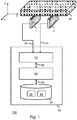
- Fig. 1 shows a system 100 for measuring a position of a motion stage 40.
- the motion stage 40 may be of any known type, including but not limited to a contactless motion stage, e.g., actuated by an inverted planar motor.
- the motion stage 40 is positionable in an operating area (not explicitly shown in Fig. 1 ) along at least two translational degrees of freedom, e.g., along the X and Y dimensions corresponding to the in-plane movement of the motion stage 40.
- the motion stage 40 has a surface on which a 2D visual pattern is provided; this aspect of the invention will be further explained with reference to Figs. 4A-9D .
- the surface is the downward-facing surface of the motion stage 40.
- 'downward' may refer to a direction of gravity when the motion stage 40 is in operation.
- the system 100 further comprises a plurality of image sensors 1, 2 which are directed at the operating area of the motion stage.
- the image sensors 1, 2 may be positioned such that they are able to observe (parts) of the visual pattern on the surface of the motion stage 40.
- the image sensors 1, 2 in the example of Fig. 1 are positioned below the motion stage 40 while facing with their observation (sensing) direction upwards.
- the image sensors 1, 2 each comprise a 1D sensor array providing 1D image data.
- each of the image sensors 1, 2 may be a Contact Image Sensor (CIS), a line scan camera, or a 2D image sensor of which only one or a small number of rows or columns are read out.
- each image sensor may be constituted by an elongated sensor array, e.g., being 1D or having an aspect ratio of sensor elements of 1:5, 1:10, 1:20 or even higher.
- Fig. 1 only shows two image sensors 1, 2, a larger number of image sensors 1, 2 may be used as well.
- the number and relative positions of the image sensors 1, 2 may be selected so that at least two of the plurality of image sensors 1, 2 observe the visual pattern at any given time when the motion stage is positioned within the operating area. Accordingly, the acquired sensor data may at any given time provide at least two one-dimensional intersections of the visual pattern.
- the system 100 further comprises a processing subsystem 60.
- the processing subsystem 60 comprises a sensor data interface 70 configured to receive the sensor data 30, 31 of the image sensors 1, 2.
- the sensor data interface 70 may take various forms, including but not limited to CameraLink interfaces or other serial video interfaces, USB interfaces, FireWire interfaces, Network interfaces, etc.
- the sensor data interface 70 may be an input interface of a type which matches the type of output interface of the image sensors 1, 2.
- the processing subsystem 60 further comprises a storage 80 which comprises instruction data 82 representing a set of instructions and pattern data 84 indicative of the 2D visual pattern.
- the storage 80 may take various forms, including volatile memory such as RAM, non-volatile memory such as Flash as well as other types of storage, e.g., a hard drive or Solid State Disk (SSD) or an array thereof.
- volatile memory such as RAM
- non-volatile memory such as Flash
- other types of storage e.g., a hard drive or Solid State Disk (SSD) or an array thereof.
- SSD Solid State Disk
- the storage 80 may also be distributed in that the instruction data 82 may be stored on a different storage subsystem than the pattern data 84.
- the processing subsystem 60 further comprises a processor 90 configured to communicate with the sensor data interface 70 and the storage 80 via internal data communication 92, 94 and to execute the set of instructions during operation of the system 100.
- the set of instructions when executed by the processor 90, cause the processor 90 to determine the position of the motion stage 40 by matching the sensor data 30, 31 with the pattern data 84 on the basis of the relative positions of the at least two image sensors 1, 2 being known.
- These relative positions may be obtained by manual pre-configuration or automatic calibration or in any other suitable manner, and may be made known to the processor 90 by being provided as separate data in the storage 80 (not explicitly shown in Fig. 1 ), or by being part of the instruction data 82, or in any other suitable manner.
- the relative positions being 'known' refers to these being made available to the system in the form of data. It will be appreciated that the positions indicated such data may deviate from the actual positions, e.g., due to measurement errors.
- the processing subsystem 60 of the system 100 may be embodied as, or in, a device or apparatus, such as a workstation or embedded computer.
- the device or apparatus may comprise one or more (micro)processors which execute appropriate software.
- the processor 90 of the processing subsystem 60 may be embodied by one or more of these (micro)processors.
- Software implementing functionality of the processing subsystem 60 may have been downloaded and/or stored in a corresponding memory or memories, e.g., in volatile memory such as RAM or in non-volatile memory such as Flash.
- the processor 90 may be implemented in the device or apparatus in the form of programmable logic, e.g., as a Field-Programmable Gate Array (FPGA).
- FPGA Field-Programmable Gate Array
- the sensor data interface 70 may be implemented by a respective interface of the device or apparatus.
- each unit of the processing subsystem 60 may be implemented in the form of a circuit.
- the processing subsystem 60 may also be implemented in a distributed manner, e.g., involving different devices or apparatuses.
- the distribution may be in accordance with a client-server model, e.g., using a server and a thin-client workstation.
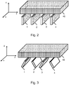
- Figs. 2 and 3 show two different configuration of contact image sensors 1-4.
- the contact image sensors 1-4 are arranged for accurately measuring 3 DOFs (X, Y, Rz) of the motion stage 40
- the contact image sensors 1-4 are arranged for measuring 6 DOFs (X, Y, Z, Rx, Ry and Rz) of the motion stage 40.
- the image sensors 1-4 may be arranged such that an observation direction of each respective image sensor is substantially at a zero angle to the normal of the surface of the motion stage 40 when the motion stage is positioned in the operating area. Effectively, in the example of Fig. 2 , this implies that the image sensors 1-4 point upwards, opposite to the direction of gravity.
- the plurality of image sensors 1-4 may be arranged such that a first subset, namely image sensors 1, 3, have an observation direction which is at a first non-zero angle with the normal of the surface of the motion stage 40 when the motion stage is positioned in the operating area, and a second subset, in this example image sensors 2, 4, have an observation direction which is at a second non-zero angle with the normal of the surface of the motion stage 40.
- each image sensor may be tilted around a length axis of the respective image sensor.
- the image sensors 1-4 may be tilted around the Rx axis with alternating tilting directions for each row, e, g., +30°,-30°,+30°,-30°,... or +45°,-45°,+45°,-45°, ...
- the number and relative positions of the image sensors 1-4 may be selected such that not only at least two of the image sensors observe the visual pattern, but also that amongst those image sensors, the visual pattern is observed from at least two different angles.
- the image sensors 1-4 of Figs. 2 and 3 may be arranged in a grid which is spaced apart to cover the operational area with only a limited amount of image sensors, and thus a limited amount of sensor data.
- Figs. 4A-9D show the result of performance simulations of different configurations of the system, which include different visual patterns, different number and positions of image sensors, different tilting of image sensors, the presence or lack of disturbances and sensor noise, etc.
- the image sensors are contact image sensors, and the motion stage is simulated to move according to a predetermined movement trajectory (not explicitly shown).
- the visual pattern is by way of example a line pattern, being a nested polygon. The algorithm used for calculating the position from the sensor data and the pattern data will be described further onwards, but is in these examples based on the detection of line points (peaks) in the sensor data.
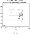
- Figs. 4A-4F relate to a performance simulation of a first embodiment in which, as illustrated in Fig. 4A , the contact image sensors 1-16 are arranged in a grid 20 of 4x4 contact image sensors which are arranged to cover an operational area 41 of the motion stage.
- the X-axis 200 corresponds to an X-position
- the Y-axis 202 corresponds to a Y-position in the operational area 41.
- the visual pattern 50 provided on the motion stage; the motion stage itself is not shown to avoid impairing the legibility of the figures.
- Fig. 4A further shows, above the figure, the current position of the center of the motion stage in the 6 DOFs.
- intersection points of the visual pattern with each respective image sensor's observation area are shown in Fig. 4A as dots 230.
- the intersection points are intersection with a line of the line pattern 50, they are also referred to as line points, and may be detected by detecting peaks in the sensor data.
- the position of the dots 230 reflect the respective tilting of the contact image sensors 1-16 by +45° or -45°.
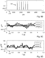
- Fig. 4B shows an exemplary output of one of the contact image sensors, being in this example contact image sensor 11.
- the horizontal axis 210 shows the pixel position
- the vertical axis 220 shows the sensor data value.
- the peaks corresponding to the line points 230 may be detected by signal analysis, as described further onwards.
- Such geometric parameters which may be known to the system and used in determining the position of the motion stage include, but are not limited to, position of a sensor, orientation of a sensor, pitch of sensor pixels, position errors of (sets of) pixels, line-of-sight angle error of (sets of) pixels, errors in the visual pattern, etc.
- Fig. 4C show the measurement accuracy which may be obtained in X, Y and Z and Fig. 4D shows the measurement accuracy in Rx, Ry and Rz when the motion stage moves according to a predetermined movement trajectory over time (T in seconds, horizontal axis 240) without such disturbances and sensor noise.
- the accuracy is calculated as a difference between the actual (simulated) position of the motion stage and the measured position, resulting in the case of Fig. 4C in a translational measurement error 250 (expressed in ⁇ m) and in the case of Fig. 4D in a rotational measurement error 260 (expressed in ⁇ rad). Any estimation errors are typically small and due to a limited computational accuracy.
- Figs. 4E and 4F are similar to Figs. 4C and 4D , respectively, except that the presence of disturbances in the geometric parameters has been simulated by adding/subtracting 10 ⁇ m for various geometric parameters, such as the 'known' sensor positions and the gridline positions as indicated by the pattern data, and adding 0.1% (addititive) sensor noise. It can be seen that compared to Figs. 4C and 4D , the measurement accuracy decreases but may still be considered acceptable for various use-cases.
- Figs. 5A-5D show the performance simulation of a second embodiment which is similar to that of Figs. 4A-B , E-F .
- a nested pentagon 51 is used as visual pattern, resulting in a different set of detected line points 231. It can be seen that the measurement accuracy is roughly similar to that of Figs. 4A-B , E-F .
- Figs. 6A-6D show the performance simulation of a third embodiment which is similar to that of Figs. 4A-B , E-F , however, with the sensor tilt being now reduced from 45 to 20 degrees. It can be seen by comparing Fig. 6C with Fig. 4E and Fig. 6D with Fig. 4F that such reduced tilting improves the accuracy of the in-plane position measurement, e.g., in X, Y and Rz, but reduces the accuracy of the out-of-plane measurement, e.g., in Rx, Ry and Z.
- Figs. 7A-7D show the performance simulation of a fourth embodiment which is similar to that of 4A-B, E-F, however, with the image sensors 1-16 now being arranged in a different grid 21 of image sensors, e.g., having a 2x8 size instead of 4x4, while also being rotated within the X-Y plane, thereby resulting in a different set of detected line points 233.
- the measurement accuracy may be considered acceptable for various use-cases.
- Figs. 8A-8D show the performance simulation of a fifth embodiment in which the contact image sensors 1-16 are arranged for 3 DOF measurement and thus not tilted, which also follows from the detected line points 234 being shown as directly underlying the contact image sensors in Fig. 8A .
- E-F which show the measurement optimized for 6 DOF
- the measurement optimized for 3 DOF yields a (slightly) improved accuracy for the in-plane position measurement, e.g., in X, Y and Rz.
- Figs. 9A-9D show the performance simulation of a sixth embodiment in which only two contact image sensors 1-2 are used in a 2x1 grid 22 to cover a smaller operational area 42 and with a smaller visual pattern 52 provided on the motion stage.
- Fig. 9B shows the sensor data of the contact image sensor 1, indicating the line points 235.
- an algorithm may be used.
- the algorithm may be represented by the instruction data of the processor.
- the algorithm may broadly involve, for a line pattern:
- the algorithm may be the embodied by the following Matlab code.
- a function 'obtain_position' may be called to estimate the 3 DOF/6 DOF position.
- peaks may be detected corresponding to observed lines of the line pattern.
- the detected line points may be mapped onto the line pattern of the motion stage as well as possible by optimizing the 3 DOF/6 DOF position of the motion stage.
- the image sensors may be distributed such that at any time at least 6 line points may be detected and each DOF shows a unique gradient with respect to other DOFs, e.g., the Jacobian matrix is not singular at that point. Accuracy may decrease if multiple gradient start to look similar. In general, the accuracy of the measurement increases with the amount of detected line points, as by using more detected line points, (pseudo-)random effects like noise, tolerances, etc. may be averaged and thereby their influence on the position measurement may be reduced.
- the grid of image sensors and the visual pattern may be selected to obtain a trade-off in accuracies across the DOFs. For example, by tilting the image sensors further away from the normal of the surface of the motion stage, the measurement of the position of the motion stage may be more accurate in Z-direction and less accurate in X,Y-direction.
- the optimal distribution of the image sensors may be closely related to the used visual pattern and may be determined theoretically or empirically, either jointly or for a particular visual pattern. It will be appreciated that also a sub-optimal distribution of the image sensors may provide sufficient accuracy for some use-cases.
- the distribution of image sensors and the visual pattern to reduce or prevent the occurrence of singular points when determining the position of the motion stage.
- the visual pattern only consists of lines in the X-direction, and the motion stage moves in the X-direction, the X-position cannot be determined as it represents a singular point. This may be avoided by ensuring that the visual pattern contains detail in the X-direction and thereby is translationally unique, or at least represents only a limited number of singular points.
- the visual pattern may be designed to contain horizontal and vertical detail.
- the visual pattern may also be designed to be rotation asymmetric, rather than a rotation symmetric pattern such as a circle.
- a rotation symmetric pattern such as a circle.
- the visual pattern is a nested polygon, such as a nested triangle, one side of the triangle may have thicker or more lines.
- a spiral is another example.
- the visual pattern may also be a random pattern. In general, it may be tried to ensure that the lines of a line pattern are sufficiently isolated from each other to enable their intersection to be reliably detected from the sensor data.
- the visual pattern is a line pattern
- black lines on a white background may be used to improve contrast.
- RGB image sensors a combination of 3 different grids in the colors red, green, and blue may be used. This may provide more detected line points which may be used to improve the measurement accuracy.
- the visual pattern does not need to be a line pattern, but may also be another pattern, such as an image.
- a detected intensity profile may be matched to the image.
- the system may further comprise one or more light sources to illuminate the visual pattern on the surface of the motion stage.
- light strips may be integrated with CIS scanners or provided separately.
- the coils may be placed beside the image sensors while the magnets may be placed in the bottom of the motion stage.
- the accuracy of the measurement may depend on the resolution of the image sensors.
- the inventors have considered, as a very rough rule, that the spacing between the sensor elements may be roughly 1 order higher than the overall accuracy.
- the image sensor resolution may be 10-100 ⁇ m, which corresponds to approximately 300-2400 dpi.
- more than 6 DOFs of movement may be measured, such as deformations of the motion stage.
- deformations may be induced by temperature variations, e.g., thermal expansion, or by internal flexibilities in the motion stage.
- a sampling rate in the order of 1 kHz and an accuracy in the order of 1-10 ⁇ m may be used. If an actuator is added to the system, such as an inverted planar motor, the loop may be closed in that the measured position may be used to control the actuation of the motion stage. In some embodiments, the measurement system may be used for actuator commutation as it may provide an absolute position, e.g., relative to a known absolute reference such as the absolute position of the image sensors.
- Fig. 10 shows a computer-implemented method 300 for measuring a position of a motion stage positionable in an operating area along at least two translational degrees of freedom and having a surface on which a two-dimensional visual pattern is provided.
- the method 300 may, but does not need to, correspond to an operation of the system 100 as described with reference to Fig. 1 and others.
- the method 300 comprises, in an operation titled "OBTAINING SENSOR DATA", obtaining 310 from a plurality of image sensors which each comprise a one-dimensional sensor array and are i) directed at the operating area of the motion stage and ii) positioned at known relative positions to each other, sensor data of at least two of the plurality of image sensors that observe the visual pattern, thereby obtaining sensor data representing at least two one-dimensional intersections of the visual pattern.
- the method 300 further comprises, in an operation titled "OBTAINING PATTERN DATA", obtaining 320 pattern data indicative of the visual pattern.
- the method 300 further comprises, in an operation titled "ESTIMATING POSITION OF MOTION STAGE", determining 330 the position of the motion stage by matching the sensor data with the pattern data on the basis of the known relative positions of the at least two image sensors.
- Fig. 10 may be performed in any suitable order, e.g., consecutively, simultaneously, or a combination thereof, subject to, where applicable, a particular order being necessitated, e.g., by input/output relations.
- the steps 310, 320 may be performed simultaneously or in reverse order.
- the method may be implemented on a computer as a computer implemented method, as dedicated hardware, or as a combination of both.
- instructions for the computer e.g., executable code
- the executable code may be stored in a transitory or non-transitory manner. Examples of computer readable mediums include memory devices, optical storage devices, integrated circuits, servers, online software, etc.
- Fig. 11 shows an optical disc 400.
- the invention also applies to computer programs, particularly computer programs on or in a carrier, adapted to put the invention into practice.
- the program may be in the form of a source code, an object code, a code intermediate source and an object code such as in a partially compiled form, or in any other form suitable for use in the implementation of the method according to the invention.
- a program may have many different architectural designs.
- a program code implementing the functionality of the method or system according to the invention may be sub-divided into one or more sub-routines. Many different ways of distributing the functionality among these sub-routines will be apparent to the skilled person.
- the sub-routines may be stored together in one executable file to form a self-contained program.
- Such an executable file may comprise computer-executable instructions, for example, processor instructions and/or interpreter instructions (e.g. Java interpreter instructions).
- one or more or all of the sub-routines may be stored in at least one external library file and linked with a main program either statically or dynamically, e.g. at run-time.
- the main program contains at least one call to at least one of the sub-routines.
- the sub-routines may also comprise function calls to each other.
- An embodiment relating to a computer program product comprises computer-executable instructions corresponding to each processing stage of at least one of the methods set forth herein. These instructions may be sub-divided into sub-routines and/or stored in one or more files that may be linked statically or dynamically.
- Another embodiment relating to a computer program product comprises computer-executable instructions corresponding to each means of at least one of the systems and/or products set forth herein. These instructions may be sub-divided into sub-routines and/or stored in one or more files that may be linked statically or dynamically.
- the carrier of a computer program may be any entity or device capable of carrying the program.
- the carrier may include a data storage, such as a ROM, for example, a CD ROM or a semiconductor ROM, or a magnetic recording medium, for example, a hard disk.
- the carrier may be a transmissible carrier such as an electric or optical signal, which may be conveyed via electric or optical cable or by radio or other means.
- the carrier may be constituted by such a cable or other device or means.
- the carrier may be an integrated circuit in which the program is embedded, the integrated circuit being adapted to perform, or used in the performance of, the relevant method.
Landscapes
- Physics & Mathematics (AREA)
- General Physics & Mathematics (AREA)
- Engineering & Computer Science (AREA)
- Human Computer Interaction (AREA)
- Manufacturing & Machinery (AREA)
- Automation & Control Theory (AREA)
- Length Measuring Devices By Optical Means (AREA)
Priority Applications (2)
| Application Number | Priority Date | Filing Date | Title |
|---|---|---|---|
| EP17181038.5A EP3428751A1 (de) | 2017-07-12 | 2017-07-12 | Messung der position einer beweglichen bühne |
| PCT/EP2018/068178 WO2019011764A1 (en) | 2017-07-12 | 2018-07-05 | POSITION MEASUREMENT OF A MOBILE STAGE |
Applications Claiming Priority (1)
| Application Number | Priority Date | Filing Date | Title |
|---|---|---|---|
| EP17181038.5A EP3428751A1 (de) | 2017-07-12 | 2017-07-12 | Messung der position einer beweglichen bühne |
Publications (1)
| Publication Number | Publication Date |
|---|---|
| EP3428751A1 true EP3428751A1 (de) | 2019-01-16 |
Family
ID=59506053
Family Applications (1)
| Application Number | Title | Priority Date | Filing Date |
|---|---|---|---|
| EP17181038.5A Withdrawn EP3428751A1 (de) | 2017-07-12 | 2017-07-12 | Messung der position einer beweglichen bühne |
Country Status (2)
| Country | Link |
|---|---|
| EP (1) | EP3428751A1 (de) |
| WO (1) | WO2019011764A1 (de) |
Cited By (3)
| Publication number | Priority date | Publication date | Assignee | Title |
|---|---|---|---|---|
| CN110617766A (zh) * | 2019-10-16 | 2019-12-27 | 广东博智林机器人有限公司 | 平面位姿测量方法、装置及存储介质 |
| CN115268372A (zh) * | 2021-07-23 | 2022-11-01 | 中国航空油料集团有限公司 | 移动井盖的控制方法和系统 |
| TWI819548B (zh) * | 2022-03-25 | 2023-10-21 | 大陸商業成科技(成都)有限公司 | 光學量測設備及其校正方法 |
Citations (4)
| Publication number | Priority date | Publication date | Assignee | Title |
|---|---|---|---|---|
| US5126648A (en) * | 1990-03-22 | 1992-06-30 | Megamation Incorporated | High resolution piggyback linear motor design for placement systems and the like |
| US20110303831A1 (en) * | 2010-06-15 | 2011-12-15 | Canon Kabushiki Kaisha | Rotary encoder that detects rotation angle |
| EP2708855A2 (de) * | 2012-09-13 | 2014-03-19 | Canon Kabushiki Kaisha | Zweidimensionaler Absolutwertgeber und Maßstab |
| JP2015105829A (ja) * | 2013-11-28 | 2015-06-08 | 株式会社ニコン | エンコーダ用スケール、エンコーダ、駆動装置、及びステージ装置 |
Family Cites Families (1)
| Publication number | Priority date | Publication date | Assignee | Title |
|---|---|---|---|---|
| US6188058B1 (en) * | 1998-09-17 | 2001-02-13 | Agilent Technologies Inc. | System for taking displacement measurements having photosensors with imaged pattern arrangement |
-
2017
- 2017-07-12 EP EP17181038.5A patent/EP3428751A1/de not_active Withdrawn
-
2018
- 2018-07-05 WO PCT/EP2018/068178 patent/WO2019011764A1/en active Application Filing
Patent Citations (4)
| Publication number | Priority date | Publication date | Assignee | Title |
|---|---|---|---|---|
| US5126648A (en) * | 1990-03-22 | 1992-06-30 | Megamation Incorporated | High resolution piggyback linear motor design for placement systems and the like |
| US20110303831A1 (en) * | 2010-06-15 | 2011-12-15 | Canon Kabushiki Kaisha | Rotary encoder that detects rotation angle |
| EP2708855A2 (de) * | 2012-09-13 | 2014-03-19 | Canon Kabushiki Kaisha | Zweidimensionaler Absolutwertgeber und Maßstab |
| JP2015105829A (ja) * | 2013-11-28 | 2015-06-08 | 株式会社ニコン | エンコーダ用スケール、エンコーダ、駆動装置、及びステージ装置 |
Cited By (3)
| Publication number | Priority date | Publication date | Assignee | Title |
|---|---|---|---|---|
| CN110617766A (zh) * | 2019-10-16 | 2019-12-27 | 广东博智林机器人有限公司 | 平面位姿测量方法、装置及存储介质 |
| CN115268372A (zh) * | 2021-07-23 | 2022-11-01 | 中国航空油料集团有限公司 | 移动井盖的控制方法和系统 |
| TWI819548B (zh) * | 2022-03-25 | 2023-10-21 | 大陸商業成科技(成都)有限公司 | 光學量測設備及其校正方法 |
Also Published As
| Publication number | Publication date |
|---|---|
| WO2019011764A1 (en) | 2019-01-17 |
Similar Documents
| Publication | Publication Date | Title |
|---|---|---|
| Wasenmüller et al. | Comparison of kinect v1 and v2 depth images in terms of accuracy and precision | |
| CN107431788B (zh) | 视觉系统中的基于图像的托盘对准和管槽定位的方法和系统 | |
| US9552514B2 (en) | Moving object detection method and system | |
| CN107687855B (zh) | 机器人定位方法、装置及机器人 | |
| US20190096080A1 (en) | Machine vision system and method for identifying locations of target elements | |
| CN103377471B (zh) | 物体定位方法和装置、最优摄像机对确定方法和装置 | |
| JP6977921B2 (ja) | マッピング方法、画像収集処理システム及び測位方法 | |
| EP3428751A1 (de) | Messung der position einer beweglichen bühne | |
| CN104735444A (zh) | 根据直线特征执行视觉系统平面手眼校准的系统和方法 | |
| CN103824275A (zh) | 在图像中搜寻鞍点状结构并测定其信息的系统和方法 | |
| JP6035031B2 (ja) | 複数の格子を用いた三次元形状計測装置 | |
| US9116578B2 (en) | Optical distance determination device, optical touch monitoring system and method for measuring distance of a touch point on an optical touch panel | |
| CN104515477A (zh) | 三维测定装置、三维测定方法以及基板的制造方法 | |
| EP3660452B1 (de) | Positionierungssystem und positionierungsverfahren | |
| CN111380668B (zh) | 一种深度相机的精度检测系统及其精度检测方法 | |
| KR102066862B1 (ko) | Rgb-d 카메라를 이용한 컨베이어용 고속 박스 크기 측정 장치 및 방법 | |
| CN102314263A (zh) | 光学触控屏幕系统、光学距离判断装置及其方法 | |
| KR102049666B1 (ko) | 비전 기반 위치 추정 기법을 이용한 6-자유도 상대 변위 추정 방법 및 그 장치 | |
| JP7020074B2 (ja) | 表面特性取得装置、表面特性取得システム及びプログラム | |
| JP2020197495A (ja) | 情報処理装置、計測装置、情報処理方法、プログラム、システム及び物品の製造方法 | |
| KR20150111944A (ko) | 전기 회로의 3차원 이미지를 결정하기 위한 시스템 | |
| KR102502100B1 (ko) | 깊이 센서와 컬러 카메라를 이용한 실시간 객체 위치 측정을 위한 전자 장치 및 그의 동작 방법 | |
| CN113269836B (zh) | 3d相机标定方法、装置、计算机设备及其存储介质 | |
| KR102247057B1 (ko) | 인공신경망을 이용한 슬라브 길이 연산 방법 및 그 장치 | |
| KR101008328B1 (ko) | 모아레를 이용한 3차원 측정장치의 격자이동방법 및격자이동장치 |
Legal Events
| Date | Code | Title | Description |
|---|---|---|---|
| PUAI | Public reference made under article 153(3) epc to a published international application that has entered the european phase |
Free format text: ORIGINAL CODE: 0009012 |
|
| AK | Designated contracting states |
Kind code of ref document: A1 Designated state(s): AL AT BE BG CH CY CZ DE DK EE ES FI FR GB GR HR HU IE IS IT LI LT LU LV MC MK MT NL NO PL PT RO RS SE SI SK SM TR |
|
| AX | Request for extension of the european patent |
Extension state: BA ME |
|
| STAA | Information on the status of an ep patent application or granted ep patent |
Free format text: STATUS: THE APPLICATION IS DEEMED TO BE WITHDRAWN |
|
| 18D | Application deemed to be withdrawn |
Effective date: 20190717 |