EP3428585A1 - Three dimensional printer and liquid level sensing method - Google Patents
Three dimensional printer and liquid level sensing method Download PDFInfo
- Publication number
- EP3428585A1 EP3428585A1 EP18166155.4A EP18166155A EP3428585A1 EP 3428585 A1 EP3428585 A1 EP 3428585A1 EP 18166155 A EP18166155 A EP 18166155A EP 3428585 A1 EP3428585 A1 EP 3428585A1
- Authority
- EP
- European Patent Office
- Prior art keywords
- tank
- capacitive sensing
- forming material
- electrode pair
- liquid level
- Prior art date
- Legal status (The legal status is an assumption and is not a legal conclusion. Google has not performed a legal analysis and makes no representation as to the accuracy of the status listed.)
- Withdrawn
Links
Images


Classifications
-
- B—PERFORMING OPERATIONS; TRANSPORTING
- B29—WORKING OF PLASTICS; WORKING OF SUBSTANCES IN A PLASTIC STATE IN GENERAL
- B29C—SHAPING OR JOINING OF PLASTICS; SHAPING OF MATERIAL IN A PLASTIC STATE, NOT OTHERWISE PROVIDED FOR; AFTER-TREATMENT OF THE SHAPED PRODUCTS, e.g. REPAIRING
- B29C64/00—Additive manufacturing, i.e. manufacturing of three-dimensional [3D] objects by additive deposition, additive agglomeration or additive layering, e.g. by 3D printing, stereolithography or selective laser sintering
- B29C64/30—Auxiliary operations or equipment
- B29C64/386—Data acquisition or data processing for additive manufacturing
- B29C64/393—Data acquisition or data processing for additive manufacturing for controlling or regulating additive manufacturing processes
-
- B—PERFORMING OPERATIONS; TRANSPORTING
- B33—ADDITIVE MANUFACTURING TECHNOLOGY
- B33Y—ADDITIVE MANUFACTURING, i.e. MANUFACTURING OF THREE-DIMENSIONAL [3-D] OBJECTS BY ADDITIVE DEPOSITION, ADDITIVE AGGLOMERATION OR ADDITIVE LAYERING, e.g. BY 3-D PRINTING, STEREOLITHOGRAPHY OR SELECTIVE LASER SINTERING
- B33Y30/00—Apparatus for additive manufacturing; Details thereof or accessories therefor
-
- B—PERFORMING OPERATIONS; TRANSPORTING
- B29—WORKING OF PLASTICS; WORKING OF SUBSTANCES IN A PLASTIC STATE IN GENERAL
- B29C—SHAPING OR JOINING OF PLASTICS; SHAPING OF MATERIAL IN A PLASTIC STATE, NOT OTHERWISE PROVIDED FOR; AFTER-TREATMENT OF THE SHAPED PRODUCTS, e.g. REPAIRING
- B29C64/00—Additive manufacturing, i.e. manufacturing of three-dimensional [3D] objects by additive deposition, additive agglomeration or additive layering, e.g. by 3D printing, stereolithography or selective laser sintering
- B29C64/10—Processes of additive manufacturing
- B29C64/106—Processes of additive manufacturing using only liquids or viscous materials, e.g. depositing a continuous bead of viscous material
- B29C64/124—Processes of additive manufacturing using only liquids or viscous materials, e.g. depositing a continuous bead of viscous material using layers of liquid which are selectively solidified
- B29C64/129—Processes of additive manufacturing using only liquids or viscous materials, e.g. depositing a continuous bead of viscous material using layers of liquid which are selectively solidified characterised by the energy source therefor, e.g. by global irradiation combined with a mask
- B29C64/135—Processes of additive manufacturing using only liquids or viscous materials, e.g. depositing a continuous bead of viscous material using layers of liquid which are selectively solidified characterised by the energy source therefor, e.g. by global irradiation combined with a mask the energy source being concentrated, e.g. scanning lasers or focused light sources
-
- B—PERFORMING OPERATIONS; TRANSPORTING
- B29—WORKING OF PLASTICS; WORKING OF SUBSTANCES IN A PLASTIC STATE IN GENERAL
- B29C—SHAPING OR JOINING OF PLASTICS; SHAPING OF MATERIAL IN A PLASTIC STATE, NOT OTHERWISE PROVIDED FOR; AFTER-TREATMENT OF THE SHAPED PRODUCTS, e.g. REPAIRING
- B29C64/00—Additive manufacturing, i.e. manufacturing of three-dimensional [3D] objects by additive deposition, additive agglomeration or additive layering, e.g. by 3D printing, stereolithography or selective laser sintering
- B29C64/20—Apparatus for additive manufacturing; Details thereof or accessories therefor
- B29C64/255—Enclosures for the building material, e.g. powder containers
-
- B—PERFORMING OPERATIONS; TRANSPORTING
- B29—WORKING OF PLASTICS; WORKING OF SUBSTANCES IN A PLASTIC STATE IN GENERAL
- B29C—SHAPING OR JOINING OF PLASTICS; SHAPING OF MATERIAL IN A PLASTIC STATE, NOT OTHERWISE PROVIDED FOR; AFTER-TREATMENT OF THE SHAPED PRODUCTS, e.g. REPAIRING
- B29C64/00—Additive manufacturing, i.e. manufacturing of three-dimensional [3D] objects by additive deposition, additive agglomeration or additive layering, e.g. by 3D printing, stereolithography or selective laser sintering
- B29C64/30—Auxiliary operations or equipment
- B29C64/307—Handling of material to be used in additive manufacturing
- B29C64/321—Feeding
-
- B—PERFORMING OPERATIONS; TRANSPORTING
- B33—ADDITIVE MANUFACTURING TECHNOLOGY
- B33Y—ADDITIVE MANUFACTURING, i.e. MANUFACTURING OF THREE-DIMENSIONAL [3-D] OBJECTS BY ADDITIVE DEPOSITION, ADDITIVE AGGLOMERATION OR ADDITIVE LAYERING, e.g. BY 3-D PRINTING, STEREOLITHOGRAPHY OR SELECTIVE LASER SINTERING
- B33Y10/00—Processes of additive manufacturing
-
- B—PERFORMING OPERATIONS; TRANSPORTING
- B33—ADDITIVE MANUFACTURING TECHNOLOGY
- B33Y—ADDITIVE MANUFACTURING, i.e. MANUFACTURING OF THREE-DIMENSIONAL [3-D] OBJECTS BY ADDITIVE DEPOSITION, ADDITIVE AGGLOMERATION OR ADDITIVE LAYERING, e.g. BY 3-D PRINTING, STEREOLITHOGRAPHY OR SELECTIVE LASER SINTERING
- B33Y50/00—Data acquisition or data processing for additive manufacturing
- B33Y50/02—Data acquisition or data processing for additive manufacturing for controlling or regulating additive manufacturing processes
-
- G—PHYSICS
- G01—MEASURING; TESTING
- G01F—MEASURING VOLUME, VOLUME FLOW, MASS FLOW OR LIQUID LEVEL; METERING BY VOLUME
- G01F23/00—Indicating or measuring liquid level or level of fluent solid material, e.g. indicating in terms of volume or indicating by means of an alarm
- G01F23/22—Indicating or measuring liquid level or level of fluent solid material, e.g. indicating in terms of volume or indicating by means of an alarm by measuring physical variables, other than linear dimensions, pressure or weight, dependent on the level to be measured, e.g. by difference of heat transfer of steam or water
- G01F23/26—Indicating or measuring liquid level or level of fluent solid material, e.g. indicating in terms of volume or indicating by means of an alarm by measuring physical variables, other than linear dimensions, pressure or weight, dependent on the level to be measured, e.g. by difference of heat transfer of steam or water by measuring variations of capacity or inductance of capacitors or inductors arising from the presence of liquid or fluent solid material in the electric or electromagnetic fields
- G01F23/263—Indicating or measuring liquid level or level of fluent solid material, e.g. indicating in terms of volume or indicating by means of an alarm by measuring physical variables, other than linear dimensions, pressure or weight, dependent on the level to be measured, e.g. by difference of heat transfer of steam or water by measuring variations of capacity or inductance of capacitors or inductors arising from the presence of liquid or fluent solid material in the electric or electromagnetic fields by measuring variations in capacitance of capacitors
- G01F23/265—Indicating or measuring liquid level or level of fluent solid material, e.g. indicating in terms of volume or indicating by means of an alarm by measuring physical variables, other than linear dimensions, pressure or weight, dependent on the level to be measured, e.g. by difference of heat transfer of steam or water by measuring variations of capacity or inductance of capacitors or inductors arising from the presence of liquid or fluent solid material in the electric or electromagnetic fields by measuring variations in capacitance of capacitors for discrete levels
-
- G—PHYSICS
- G01—MEASURING; TESTING
- G01F—MEASURING VOLUME, VOLUME FLOW, MASS FLOW OR LIQUID LEVEL; METERING BY VOLUME
- G01F23/00—Indicating or measuring liquid level or level of fluent solid material, e.g. indicating in terms of volume or indicating by means of an alarm
- G01F23/22—Indicating or measuring liquid level or level of fluent solid material, e.g. indicating in terms of volume or indicating by means of an alarm by measuring physical variables, other than linear dimensions, pressure or weight, dependent on the level to be measured, e.g. by difference of heat transfer of steam or water
- G01F23/26—Indicating or measuring liquid level or level of fluent solid material, e.g. indicating in terms of volume or indicating by means of an alarm by measuring physical variables, other than linear dimensions, pressure or weight, dependent on the level to be measured, e.g. by difference of heat transfer of steam or water by measuring variations of capacity or inductance of capacitors or inductors arising from the presence of liquid or fluent solid material in the electric or electromagnetic fields
- G01F23/263—Indicating or measuring liquid level or level of fluent solid material, e.g. indicating in terms of volume or indicating by means of an alarm by measuring physical variables, other than linear dimensions, pressure or weight, dependent on the level to be measured, e.g. by difference of heat transfer of steam or water by measuring variations of capacity or inductance of capacitors or inductors arising from the presence of liquid or fluent solid material in the electric or electromagnetic fields by measuring variations in capacitance of capacitors
- G01F23/266—Indicating or measuring liquid level or level of fluent solid material, e.g. indicating in terms of volume or indicating by means of an alarm by measuring physical variables, other than linear dimensions, pressure or weight, dependent on the level to be measured, e.g. by difference of heat transfer of steam or water by measuring variations of capacity or inductance of capacitors or inductors arising from the presence of liquid or fluent solid material in the electric or electromagnetic fields by measuring variations in capacitance of capacitors measuring circuits therefor
-
- G—PHYSICS
- G01—MEASURING; TESTING
- G01F—MEASURING VOLUME, VOLUME FLOW, MASS FLOW OR LIQUID LEVEL; METERING BY VOLUME
- G01F23/00—Indicating or measuring liquid level or level of fluent solid material, e.g. indicating in terms of volume or indicating by means of an alarm
- G01F23/22—Indicating or measuring liquid level or level of fluent solid material, e.g. indicating in terms of volume or indicating by means of an alarm by measuring physical variables, other than linear dimensions, pressure or weight, dependent on the level to be measured, e.g. by difference of heat transfer of steam or water
- G01F23/26—Indicating or measuring liquid level or level of fluent solid material, e.g. indicating in terms of volume or indicating by means of an alarm by measuring physical variables, other than linear dimensions, pressure or weight, dependent on the level to be measured, e.g. by difference of heat transfer of steam or water by measuring variations of capacity or inductance of capacitors or inductors arising from the presence of liquid or fluent solid material in the electric or electromagnetic fields
- G01F23/263—Indicating or measuring liquid level or level of fluent solid material, e.g. indicating in terms of volume or indicating by means of an alarm by measuring physical variables, other than linear dimensions, pressure or weight, dependent on the level to be measured, e.g. by difference of heat transfer of steam or water by measuring variations of capacity or inductance of capacitors or inductors arising from the presence of liquid or fluent solid material in the electric or electromagnetic fields by measuring variations in capacitance of capacitors
- G01F23/268—Indicating or measuring liquid level or level of fluent solid material, e.g. indicating in terms of volume or indicating by means of an alarm by measuring physical variables, other than linear dimensions, pressure or weight, dependent on the level to be measured, e.g. by difference of heat transfer of steam or water by measuring variations of capacity or inductance of capacitors or inductors arising from the presence of liquid or fluent solid material in the electric or electromagnetic fields by measuring variations in capacitance of capacitors mounting arrangements of probes
-
- G—PHYSICS
- G01—MEASURING; TESTING
- G01F—MEASURING VOLUME, VOLUME FLOW, MASS FLOW OR LIQUID LEVEL; METERING BY VOLUME
- G01F25/00—Testing or calibration of apparatus for measuring volume, volume flow or liquid level or for metering by volume
- G01F25/20—Testing or calibration of apparatus for measuring volume, volume flow or liquid level or for metering by volume of apparatus for measuring liquid level
Definitions
- the disclosure relates to a three-dimensional (3D) printer and a liquid level sensing method of a 3D printer.
- Photopolymer is a liquid forming material used by most of the 3D printers, and techniques such as stereolithography apparatus (SLA), digital light processing (DLP) and continuous liquid interface production (CLIP) all take the photopolymer as a printing material.
- SLA stereolithography apparatus
- DLP digital light processing
- CLIP continuous liquid interface production
- the photopolymer has a high price, so that the amount of usage becomes a major concern for users.
- the photopolymer needs to be added in the middle of the printing process, which increases a risk of printing failure. Moreover, the photopolymer is liable to be influenced by the environment, and is generally slowly cured to cause out of use as time passes.
- the usage amount of the photopolymer serving as a major consuming material is required to be accurately controlled to serve as an improvement means for optimizing a supply amount, stability of product yield and the cost, etc.
- the disclosure is directed to a three-dimensional (3D) printer, in which a capacitive sensing module is disposed outside a tank, and an electric field produced by the capacitive sensing module passes through a liquid forming material in the tank, so as to sense a variation of the liquid forming material in the tank.
- 3D three-dimensional
- An embodiment of the disclosure provides a 3D printer including a tank and at least one capacitive sensing module.
- the tank is configured to contain a liquid forming material.
- the capacitive sensing module is configured to sense a liquid level of the liquid forming material in the tank.
- the at least one capacitive sensing module includes a first electrode pair disposed beside the tank, and the first electrode pair is used for producing an electric field, and the electric field passes through the liquid forming material.
- An embodiment of the disclosure provides a liquid level sensing method, which is adapted to a 3D printer, where the 3D printer includes a tank, a plurality of capacitive sensing modules and a control module.
- the tank is configured to contain a liquid forming material.
- the capacitive sensing modules are disposed around the tank.
- the control module is electrically connected to each of the capacitive sensing modules.
- the liquid level sensing method includes: obtaining reading values of a plurality of the capacitive sensing modules by using the control module; determining whether the reading value of each of the capacitive sensing modules is smaller than a reading value of the liquid forming material at a low liquid level of the tank, so as to determine a liquid level of the liquid forming material in the tank; and performing 3D printing based on the determination result or sending a signal to request for filling the liquid forming material in the tank.
- FIG. 1 is a schematic diagram illustrating assembling of a 3D printer.
- FIG. 2 is a partial enlarged view of a 3D printer.
- FIG. 3A and FIG. 3B are side views of 3D printers according to different embodiments.
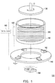
- the 3D printer 100 includes a tank 110, a capacitive sensing module 120, a forming platform 130, a control module 160, a light source 150 and a base 140.
- the 3D printer 100 is a pull-up stereolithography (SL) printer
- the tank 110 is used for containing a liquid forming material 200
- the control module 160 may drive the forming platform 130 to immerse in the liquid forming material 200, and drive the light source 150 to provide light to irradiate the liquid forming material 200 according to information of the cross-section layer, so as to cure the liquid forming material 200 to form the correct cross-section layer on the forming platform 130.
- the liquid forming material 200 may form a 3D object 500A under a state of curing and stacking layer-by-layer (shown in FIG. 3A ).
- the forming platform 130 and the tank 110 may all be rotated about the axis C1, such that an effect of rotating relative to the axis C1 (regardless of rotation of only the forming platform 130, only the tank 110 or both of the forming platform 130 and the tank 110) is achieved, which improves an applicable range of the 3D object 500A on the forming platform 130 in the 3D printing process, and achieves an effect of separating the cross-section layer or the 3D object 500A from a bottom of the tank 110 through the relative rotation.
- only the tank 110 is rotated, and the forming platform 130 only performs an operation of moving up and down.
- the capacitive sensing module 120 is disposed beside the tank 110 to sense a liquid level of liquid forming material 200 in the tank 110, such that the control module 160 or a user may learn or determine whether the liquid forming material 200 is enough before the 3D printing is performed.
- the capacitive sensing module 120 includes a first electrode pair 121, an insulator 122 and a shielding member 123, where the first electrode pair 121 includes a sensing electrode 121A and a ground electrode 121B, the sensing electrode 121A and the ground electrode 121B are located at a same side of the insulator 122 and face the liquid forming material 200, and the insulator 122 electrically isolates the sensing electrode 121A and the ground electrode 121B.
- the shielding member 123 is disposed on another side of the insulator 122 to back-face the first electrode pair 121, where the shielding member 123 is used for shielding signal interference of the ambient environment on the first electrode pair 121, and a material thereof may be metal, and the insulator 122 electrically isolates the shielding member 123 and the first electrode pair 121. In this way, by supplying electric power to the first electrode pair 121, an electric field is produced between the sensing electrode 121A and the ground electrode 121B, and the electric field passes through the liquid forming material 200 of the tank 110, as shown by arrows in FIG. 2 .
- the electric field in the capacitor structure is influenced as the electric field passes through different medium. Therefore, when the amount of the liquid forming material 200 is changed, a capacitance of the first electrode pair 121 is accordingly changed.
- the variation of a liquid level of the liquid forming material 200 in the tank 110 represents a variation of the dielectric substance that influences the capacitance, and the variation of the liquid level causes a variation of a reading value of the capacitance.
- the capacitance sensing module further includes a second electrode pair 320, where the second electrode pair 320 and the first electrode pair 121 are all disposed on a substrate 310 and are electrically connected to the control module 160.
- a composition structure of the second electrode pair 320 is the same with that of the first electrode pair 121 (as shown in FIG. 2 ), and the substrate 310 is similar to the composition of the insulator 122 and the shielding member 123 of FIG. 2 , so that detail thereof is not repeated.
- a difference between the two electrode pairs is that the second electrode pair 320 of the present embodiment is located beside the tank 110 and located above a predetermined liquid level of the liquid forming material 200.
- the second electrode pair 320 is used for sensing a capacitance of the ambient environment, so as to serve as a sensing reference of the first electrode pair 121.
- the change of the liquid level of the liquid forming material 200 in the tank 110 substantially includes an empty liquid level LV0, a low liquid level LV1 and a full liquid level LV2, and in an embodiment, the first electrode pair 121 substantially faces the liquid forming material 200 to simultaneously cover the range of the aforementioned liquid levels.
- the liquid forming material 200 in the tank 110 is defined to have the aforementioned liquid levels, it represents that the capacitive sensing module 120 has learned the capacitances corresponding to the different liquid levels. Therefore, when the liquid level is changed, a currently sensed capacitance may be compared with the capacitance corresponding to the aforementioned liquid level to determine a current liquid level of the liquid forming material 200.
- FIG. 3B is a side view of a 3D printer according to another embodiment of the disclosure. Referring to FIG. 3B , it is known that a size of the first electrode pair 121 may be adjusted according to an actual utilization, so as to cope with a liquid level required to be achieved by the liquid forming material 200 in the tank 110.
- FIG. 4 is a flowchart illustrating a liquid level sensing method executed by the 3D printer.
- FIG. 5A and FIG. 5B are respectively top views of the 3D printers according to different embodiments.
- FIG. 5C is a schematic diagram of a state of the 3D printer.
- the 3D printer includes a plurality of capacitive sensing modules 120A, 120B and 120C respectively surrounding the tank 110 in an equal angle configuration, i.e. relative to the axis C2, the capacitive sensing modules 120A, 120B and 120C present a configuration mode of a circumferential angle of 120 degrees. Operation timings of the capacitive sensing modules are described with reference of FIG. 4 .
- a step S01 is executed to start the capacitive sensing modules 120A, 120B and 120C to sense a status of the liquid forming material 200 in the tank 110.
- step S02 it is determined whether a reading value of each of the capacitive sensing modules 120A, 120B and 120C is the same, and such step refers to a flatness of the liquid forming material 200 in the tank 110. Namely, since the liquid forming material 200 is substantially a photopolymer having a high viscosity, mobility thereof is poor, so that the step S02 is used for determining whether the liquid forming material 200 presents a stable state.
- a step S04 by which a predetermined time is required to wait for stableness of the liquid forming material 200.
- a step S03 is executed to determine whether the reading values of the capacitive sensing modules 120A, 120B and 120C are equal to or smaller than a reading value of the low liquid level LV1, and if not, it represents that the liquid forming material 200 in the tank 110 is sufficient to execute the 3D printing of the step S06.
- a step S05 is executed, by which the liquid forming material 200 is filled in the tank 110 for supplement, and a supplementary amount thereof may be determined according to the liquid level sensed in the step S03.
- the supplement of the liquid forming material 200 may be controlled by an automatic control system according to the liquid level sensed in the step S03 to implement automatic supplement.
- the liquid level sensed in the step S03 may be converted to directly notify the required supplementary amount of the liquid forming material 200 to the user.
- the step S01 to the step S03 are again executed for further confirmation. It should be noted that whether the reading values are the same still requires considering a sensing accuracy of the capacitive sensing module, and a possible tolerance error is allowed. Moreover, as shown in FIG.
- the capacitive sensing modules 120A, 120B and 120C are substantially located on a plane S1 of a same height, so as to determine the flatness of the liquid forming material 200.
- the tank 330 of the present embodiment presents a rectangle contour, so that the capacitive sensing modules 120A, 120B and 120C of the present embodiment are disposed relative to the axis C3 (center of the tank 330) in an equal distance configuration.
- the step S03 of FIG. 4 is executed before the step S02 is executed, i.e. the step S03 is first executed to determine whether the liquid forming material 200 in the tank 110 is sufficient, and once it is determined that the liquid forming material 200 is required to be supplemented, the step S05 is executed, by which the unnecessary waiting time of the step S04 is omitted in case that the liquid forming material 200 is insufficient.
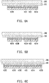
- FIG. 6A to FIG. 6C are partial enlarged views of 3D printers according to different embodiments of the disclosure.
- a sensing electrode 421A and a ground electrode 421B are respectively disposed on a same side of an insulator 422, and the sensing electrode 421A and the ground electrode 421B are substantially attached to an outer wall of the tank 110, and a shielding member 423 is disposed on another side of the insulator 422 to back-face the sensing electrode 421A and the ground electrode 421B.
- the 3D printer of the present embodiment includes two shielding members 423A, 423B, and the shielding member 423A corresponds to the sensing electrode 421A, and the shielding member 423B corresponds to the ground electrode 421B.
- the 3D printer of the present embodiment includes three shielding members 423C, 423D and 423E, where the shielding member 423C is similar to the aforementioned shielding member 423, and the shielding member 423D and the shielding member 423E are respectively located at two opposite sides of the sensing electrode 421A and the ground electrodes 421B to enclose the sensing electrode 421A and the ground electrodes 421B, so as to decrease the interference of the external environment to effectively decrease a noise.
- the capacitive sensing modules of the embodiments of FIG. 6A to FIG. 6C are simply attached to the outer wall of the tank 110, so that the capacitive sensing modules may be rotated or disassembled along with the tank 110, i.e.
- the capacitive sensing modules may be easily disassembled from the old tank and attached to the new tank. It should be noted that the capacitive sensing modules of the embodiments of FIG. 6A to FIG. 6C are also adapted to the embodiments of FIG. 1 to FIG. 5C , i.e. the capacitive sensing modules are kept a distance with the tank (i.e. disposed independent to the tank), and are not disassembled along with the replacement of the tank.
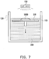
- FIG. 7 is a schematic diagram of a 3D printer according to another embodiment of the disclosure.
- the capacitive sensing module 120 is applied to a sink type SL printer, and the light source 150 is disposed above the tank 110, where a forming platform 530 is driven to gradually descend, such that a 3D object 500B is staked layer-by-layer and formed on a forming platform 530.
- the control of the liquid forming material 200 is also achieved by disposing the capacitive sensing module 120 beside the tank 110.
- the base 140 substantially has electrical conductivity, and fixing members 142 having electrical conductivity are disposed thereon, and the tank 110 disposed on the base 140 may be fixed on the base 140 through the fixing members 142. Meanwhile, the ground electrode 121B of the capacitive sensing module 120 is electrically connected to the base 140 to achieve a grounding effect.
- the base 140 is, for example, made of a metal material with electrical conductivity, which not only provides the aforementioned grounding effect, but also improves a structural strength of the tank 110. As shown in FIG.
- the tank 110 is generally made of a transparent plastic material in order to be pervious to the light produced by the light source 150, so that once the tank 110 is filled with the liquid forming material, the tank 110 is under pressure. Therefore, the tank 110 is further installed on the base 140 to effectively improve the tolerance of the tank 110 for the aforementioned pressure.
- the 3D printer of the present embodiment includes three fixing members 142A, 142B and 142C to respectively correspond to the three capacitive sensing modules 120A, 120B and 120C, where the corresponding fixing members 142A, 142B and 142C and the capacitive sensing modules 120A, 120B and 120C have an electrical connection relationship there between (for example, the ground electrode of the capacitive sensing module 142A is connected to the fixing member 142A).
- the control module 160 shown in FIG. 1
- the reading value of the capacitance of each of the capacitive sensing modules may have a fixed difference, and once the tank 110 cannot be successfully bonded to the fixing members or the installation of the tank 110 has a skew or axis deviation, etc., the aforementioned fixed difference may have abnormity or the reading values of different capacitive sensing modules 120A, 120B and 120C may have a difference.
- the electric field produced by the first electrode pair passes through the liquid forming material in the tank to sense a liquid level variation of the liquid forming material, so as to determine whether the liquid forming material before the 3D printing is sufficient, where the first electrode pair faces the liquid forming material, and coves the full liquid level, the low liquid level and the empty liquid level of the liquid forming material in the tank during a using process, so as to ensure that the capacitive sensing module is possible to deal with various variations of the liquid forming material.
- the capacitance of the ambient environment is sensed to serve as a sensing reference of the first electrode pair.
- a flatness of the liquid forming material in the tank may also be determined through a plurality of capacitance reading values of the capacitive sensing modules.
- a shielding effect is provided to the sensing electrode and the ground electrode, so as to effectively avoid the ambient environment interference to decrease the influence of noise.
Abstract
Description
- The disclosure relates to a three-dimensional (3D) printer and a liquid level sensing method of a 3D printer.
- In recent years, three-dimensional (3D) printers have been widely used in various fields, and various 3D printing techniques are quickly developed to enter an era that everything can be printed. Photopolymer is a liquid forming material used by most of the 3D printers, and techniques such as stereolithography apparatus (SLA), digital light processing (DLP) and continuous liquid interface production (CLIP) all take the photopolymer as a printing material. However, the photopolymer has a high price, so that the amount of usage becomes a major concern for users. If the amount of the material provided for the printing is more than the amount of the material needed for final curing, it will cause a waste of the cost; and if the amount of the material provided for the printing is less than the amount of the material needed for the final curing, the photopolymer needs to be added in the middle of the printing process, which increases a risk of printing failure. Moreover, the photopolymer is liable to be influenced by the environment, and is generally slowly cured to cause out of use as time passes.
- Therefore, the usage amount of the photopolymer serving as a major consuming material is required to be accurately controlled to serve as an improvement means for optimizing a supply amount, stability of product yield and the cost, etc.
- The disclosure is directed to a three-dimensional (3D) printer, in which a capacitive sensing module is disposed outside a tank, and an electric field produced by the capacitive sensing module passes through a liquid forming material in the tank, so as to sense a variation of the liquid forming material in the tank.
- An embodiment of the disclosure provides a 3D printer including a tank and at least one capacitive sensing module. The tank is configured to contain a liquid forming material. The capacitive sensing module is configured to sense a liquid level of the liquid forming material in the tank. The at least one capacitive sensing module includes a first electrode pair disposed beside the tank, and the first electrode pair is used for producing an electric field, and the electric field passes through the liquid forming material.
- An embodiment of the disclosure provides a liquid level sensing method, which is adapted to a 3D printer, where the 3D printer includes a tank, a plurality of capacitive sensing modules and a control module. The tank is configured to contain a liquid forming material. The capacitive sensing modules are disposed around the tank. The control module is electrically connected to each of the capacitive sensing modules. The liquid level sensing method includes: obtaining reading values of a plurality of the capacitive sensing modules by using the control module; determining whether the reading value of each of the capacitive sensing modules is smaller than a reading value of the liquid forming material at a low liquid level of the tank, so as to determine a liquid level of the liquid forming material in the tank; and performing 3D printing based on the determination result or sending a signal to request for filling the liquid forming material in the tank.
-
-
FIG. 1 is a schematic diagram illustrating assembling of a 3D printer. -
FIG. 2 is a partial enlarged view of a 3D printer. -
FIG. 3A and FIG. 3B are side views of 3D printers according to different embodiments. -
FIG. 4 is a flowchart illustrating a liquid level sensing method executed by a 3D printer. -
FIG. 5A and FIG. 5B are respectively top views of 3D printers according to different embodiments. -
FIG. 5C is a schematic diagram of a state of a 3D printer. -
FIG. 6A to FIG. 6C are partial enlarged views of 3D printers according to different embodiments. -
FIG. 7 is a schematic diagram of a 3D printer according to another embodiment. -
FIG. 1 is a schematic diagram illustrating assembling of a 3D printer.FIG. 2 is a partial enlarged view of a 3D printer.FIG. 3A and FIG. 3B are side views of 3D printers according to different embodiments. Referring toFIG. 1 andFIG. 2 , in the present embodiment, the3D printer 100 includes atank 110, acapacitive sensing module 120, a formingplatform 130, acontrol module 160, alight source 150 and abase 140. The3D printer 100 is a pull-up stereolithography (SL) printer, thetank 110 is used for containing a liquid formingmaterial 200, and by converting design data of a 3D model constructed through software such as computer-aided design (CAD) into a plurality of continuously stacked thin (quasi two-dimensional) cross-section layers, thecontrol module 160 may drive the formingplatform 130 to immerse in theliquid forming material 200, and drive thelight source 150 to provide light to irradiate theliquid forming material 200 according to information of the cross-section layer, so as to cure theliquid forming material 200 to form the correct cross-section layer on the formingplatform 130. Then, as the formingplatform 130 is gradually moved up along an axis C1, theliquid forming material 200 may form a3D object 500A under a state of curing and stacking layer-by-layer (shown inFIG. 3A ). - In the present embodiment, the forming
platform 130 and thetank 110 may all be rotated about the axis C1, such that an effect of rotating relative to the axis C1 (regardless of rotation of only the formingplatform 130, only thetank 110 or both of the formingplatform 130 and the tank 110) is achieved, which improves an applicable range of the3D object 500A on the formingplatform 130 in the 3D printing process, and achieves an effect of separating the cross-section layer or the3D object 500A from a bottom of thetank 110 through the relative rotation. In an embodiment, only thetank 110 is rotated, and the formingplatform 130 only performs an operation of moving up and down. - As described above, in order to accurately learn an amount of the
liquid forming material 200 in thetank 110, in the3D printer 100 of the present embodiment, thecapacitive sensing module 120 is disposed beside thetank 110 to sense a liquid level ofliquid forming material 200 in thetank 110, such that thecontrol module 160 or a user may learn or determine whether theliquid forming material 200 is enough before the 3D printing is performed. - In detail, as shown in
FIG. 2 , thecapacitive sensing module 120 includes afirst electrode pair 121, aninsulator 122 and ashielding member 123, where thefirst electrode pair 121 includes asensing electrode 121A and aground electrode 121B, thesensing electrode 121A and theground electrode 121B are located at a same side of theinsulator 122 and face theliquid forming material 200, and theinsulator 122 electrically isolates thesensing electrode 121A and theground electrode 121B. Theshielding member 123 is disposed on another side of theinsulator 122 to back-face thefirst electrode pair 121, where theshielding member 123 is used for shielding signal interference of the ambient environment on thefirst electrode pair 121, and a material thereof may be metal, and theinsulator 122 electrically isolates theshielding member 123 and thefirst electrode pair 121. In this way, by supplying electric power to thefirst electrode pair 121, an electric field is produced between thesensing electrode 121A and theground electrode 121B, and the electric field passes through theliquid forming material 200 of thetank 110, as shown by arrows inFIG. 2 . - As everyone knows, since dielectric constants of substances are different, the electric field in the capacitor structure is influenced as the electric field passes through different medium. Therefore, when the amount of the
liquid forming material 200 is changed, a capacitance of thefirst electrode pair 121 is accordingly changed. Namely, the variation of a liquid level of theliquid forming material 200 in thetank 110 represents a variation of the dielectric substance that influences the capacitance, and the variation of the liquid level causes a variation of a reading value of the capacitance. - Referring to
FIG. 3A , in the present embodiment, the capacitance sensing module further includes asecond electrode pair 320, where thesecond electrode pair 320 and thefirst electrode pair 121 are all disposed on asubstrate 310 and are electrically connected to thecontrol module 160. In this case, a composition structure of thesecond electrode pair 320 is the same with that of the first electrode pair 121 (as shown inFIG. 2 ), and thesubstrate 310 is similar to the composition of theinsulator 122 and theshielding member 123 ofFIG. 2 , so that detail thereof is not repeated. A difference between the two electrode pairs is that thesecond electrode pair 320 of the present embodiment is located beside thetank 110 and located above a predetermined liquid level of theliquid forming material 200. In other words, when the liquid level of theliquid forming material 200 is controlled to the predetermined liquid level or within a certain error range thereof, the electric field produced by thesecond electrode pair 320 does not pass through theliquid forming material 200 in thetank 110. Namely, thesecond electrode pair 320 is used for sensing a capacitance of the ambient environment, so as to serve as a sensing reference of thefirst electrode pair 121. - It should be noted that as shown in
FIG. 3A , the change of the liquid level of theliquid forming material 200 in thetank 110 substantially includes an empty liquid level LV0, a low liquid level LV1 and a full liquid level LV2, and in an embodiment, thefirst electrode pair 121 substantially faces theliquid forming material 200 to simultaneously cover the range of the aforementioned liquid levels. In other words, when theliquid forming material 200 in thetank 110 is defined to have the aforementioned liquid levels, it represents that thecapacitive sensing module 120 has learned the capacitances corresponding to the different liquid levels. Therefore, when the liquid level is changed, a currently sensed capacitance may be compared with the capacitance corresponding to the aforementioned liquid level to determine a current liquid level of theliquid forming material 200. -
FIG. 3B is a side view of a 3D printer according to another embodiment of the disclosure. Referring toFIG. 3B , it is known that a size of thefirst electrode pair 121 may be adjusted according to an actual utilization, so as to cope with a liquid level required to be achieved by theliquid forming material 200 in thetank 110. -
FIG. 4 is a flowchart illustrating a liquid level sensing method executed by the 3D printer.FIG. 5A and FIG. 5B are respectively top views of the 3D printers according to different embodiments.FIG. 5C is a schematic diagram of a state of the 3D printer. Referring toFIG. 4 andFIG. 5A , in the present embodiment, the 3D printer includes a plurality ofcapacitive sensing modules tank 110 in an equal angle configuration, i.e. relative to the axis C2, thecapacitive sensing modules FIG. 4 . Generally, before the 3D printing is performed, a step S01 is executed to start thecapacitive sensing modules liquid forming material 200 in thetank 110. Then, in step S02, it is determined whether a reading value of each of thecapacitive sensing modules liquid forming material 200 in thetank 110. Namely, since theliquid forming material 200 is substantially a photopolymer having a high viscosity, mobility thereof is poor, so that the step S02 is used for determining whether theliquid forming material 200 presents a stable state. Therefore, when the reading values of thecapacitive sensing modules liquid forming material 200 is still in a shaking state, as shown inFIG. 5C . In this case, it is required to execute a step S04, by which a predetermined time is required to wait for stableness of theliquid forming material 200. After the reading values of thecapacitive sensing modules capacitive sensing modules liquid forming material 200 in thetank 110 is sufficient to execute the 3D printing of the step S06. If yes, a step S05 is executed, by which theliquid forming material 200 is filled in thetank 110 for supplement, and a supplementary amount thereof may be determined according to the liquid level sensed in the step S03. In an embodiment, the supplement of theliquid forming material 200 may be controlled by an automatic control system according to the liquid level sensed in the step S03 to implement automatic supplement. In another embodiment, the liquid level sensed in the step S03 may be converted to directly notify the required supplementary amount of theliquid forming material 200 to the user. After the supplement is completed, the step S01 to the step S03 are again executed for further confirmation. It should be noted that whether the reading values are the same still requires considering a sensing accuracy of the capacitive sensing module, and a possible tolerance error is allowed. Moreover, as shown inFIG. 5C (only thecapacitive sensing modules capacitive sensing modules liquid forming material 200. - Referring to
FIG. 5B , different to the aforementioned embodiment, thetank 330 of the present embodiment presents a rectangle contour, so that thecapacitive sensing modules - Moreover, in another embodiment, the step S03 of
FIG. 4 is executed before the step S02 is executed, i.e. the step S03 is first executed to determine whether theliquid forming material 200 in thetank 110 is sufficient, and once it is determined that theliquid forming material 200 is required to be supplemented, the step S05 is executed, by which the unnecessary waiting time of the step S04 is omitted in case that theliquid forming material 200 is insufficient. -
FIG. 6A to FIG. 6C are partial enlarged views of 3D printers according to different embodiments of the disclosure. Referring toFIG. 6A , in the present embodiment, asensing electrode 421A and aground electrode 421B are respectively disposed on a same side of aninsulator 422, and thesensing electrode 421A and theground electrode 421B are substantially attached to an outer wall of thetank 110, and a shieldingmember 423 is disposed on another side of theinsulator 422 to back-face thesensing electrode 421A and theground electrode 421B. Referring toFIG. 6B , different to the aforementioned embodiment, the 3D printer of the present embodiment includes two shieldingmembers member 423A corresponds to thesensing electrode 421A, and the shieldingmember 423B corresponds to theground electrode 421B. Referring toFIG. 6C , the 3D printer of the present embodiment includes three shieldingmembers member 423C is similar to theaforementioned shielding member 423, and the shieldingmember 423D and the shieldingmember 423E are respectively located at two opposite sides of thesensing electrode 421A and theground electrodes 421B to enclose thesensing electrode 421A and theground electrodes 421B, so as to decrease the interference of the external environment to effectively decrease a noise. It should be noted that the capacitive sensing modules of the embodiments ofFIG. 6A to FIG. 6C are simply attached to the outer wall of thetank 110, so that the capacitive sensing modules may be rotated or disassembled along with thetank 110, i.e. when thetank 110 is to be replaced, the capacitive sensing modules may be easily disassembled from the old tank and attached to the new tank. It should be noted that the capacitive sensing modules of the embodiments ofFIG. 6A to FIG. 6C are also adapted to the embodiments ofFIG. 1 to FIG. 5C , i.e. the capacitive sensing modules are kept a distance with the tank (i.e. disposed independent to the tank), and are not disassembled along with the replacement of the tank. -
FIG. 7 is a schematic diagram of a 3D printer according to another embodiment of the disclosure. Referring toFIG. 7 , thecapacitive sensing module 120 is applied to a sink type SL printer, and thelight source 150 is disposed above thetank 110, where a formingplatform 530 is driven to gradually descend, such that a3D object 500B is staked layer-by-layer and formed on a formingplatform 530. In this case, the control of theliquid forming material 200 is also achieved by disposing thecapacitive sensing module 120 beside thetank 110. - Referring to
FIG. 1 , in the present embodiment, the base 140 substantially has electrical conductivity, and fixingmembers 142 having electrical conductivity are disposed thereon, and thetank 110 disposed on thebase 140 may be fixed on the base 140 through the fixingmembers 142. Meanwhile, theground electrode 121B of thecapacitive sensing module 120 is electrically connected to the base 140 to achieve a grounding effect. Thebase 140 is, for example, made of a metal material with electrical conductivity, which not only provides the aforementioned grounding effect, but also improves a structural strength of thetank 110. As shown inFIG. 1 , thetank 110 is generally made of a transparent plastic material in order to be pervious to the light produced by thelight source 150, so that once thetank 110 is filled with the liquid forming material, thetank 110 is under pressure. Therefore, thetank 110 is further installed on the base 140 to effectively improve the tolerance of thetank 110 for the aforementioned pressure. - Referring to
FIG. 5A , the 3D printer of the present embodiment includes three fixingmembers capacitive sensing modules members capacitive sensing modules capacitive sensing module 142A is connected to the fixingmember 142A). In this way, the control module 160 (shown inFIG. 1 ) may further determine whether thetank 110 is successfully fixed on the base 140 or whether installation of thetank 110 has a skew or axis deviation. Namely, when thetank 110 is completely fixed on the base 140 or the installation of thetank 110 is proper without skew or axis deviation, the reading value of the capacitance of each of the capacitive sensing modules may have a fixed difference, and once thetank 110 cannot be successfully bonded to the fixing members or the installation of thetank 110 has a skew or axis deviation, etc., the aforementioned fixed difference may have abnormity or the reading values of differentcapacitive sensing modules - In summary, in the 3D printer, by configuring at least one capacitive sensing module outside the tank, the electric field produced by the first electrode pair passes through the liquid forming material in the tank to sense a liquid level variation of the liquid forming material, so as to determine whether the liquid forming material before the 3D printing is sufficient, where the first electrode pair faces the liquid forming material, and coves the full liquid level, the low liquid level and the empty liquid level of the liquid forming material in the tank during a using process, so as to ensure that the capacitive sensing module is possible to deal with various variations of the liquid forming material. Meanwhile, by configuring the second electrode pair, the capacitance of the ambient environment is sensed to serve as a sensing reference of the first electrode pair.
- Moreover, by configuring a plurality of the capacitive sensing modules around the tank, besides that the single capacitive sensing module may sense the liquid level of the liquid forming material, a flatness of the liquid forming material in the tank may also be determined through a plurality of capacitance reading values of the capacitive sensing modules.
- Moreover, by configuring the shielding members at each of the capacitive sensing modules, a shielding effect is provided to the sensing electrode and the ground electrode, so as to effectively avoid the ambient environment interference to decrease the influence of noise.
Claims (16)
- A three-dimensional printer (100), comprising:a tank (110, 330), configured to contain a liquid forming material (200); andat least one capacitive sensing module (120, 120A, 120B, 120C), configured to sense a liquid level of the liquid forming material (200) in the tank (110, 330), the at least one capacitive sensing module (120, 120A, 120B, 120C) comprising a first electrode pair (121) disposed beside the tank (110, 330), wherein the first electrode pair (121) is used for producing an electric field, and the electric field passes through the liquid forming material (200).
- The three-dimensional printer as claimed in claim 1, wherein the at least one capacitive sensing module (120, 120A, 120B, 120C) further comprises an insulator (122, 422), the first electrode pair (121) comprises a sensing electrode (121A, 421A) and a ground electrode (121B, 421B), the sensing electrode (121A, 421A) and the ground electrode (121B, 421B) are located at a same side of the insulator (122, 422) and face the liquid forming material (200), and the insulator (122, 422) electrically isolates the sensing electrode (121A, 421A) and the ground electrode (121B, 421B).
- The three-dimensional printer as claimed in claim 2, wherein the at least one capacitive sensing module (120, 120A, 120B, 120C) further comprises at least one shielding member (123, 423, 423A, 423B, 423C, 423D, 423E) disposed on the insulator (122, 422) and back-facing the first electrode pair (121), the at least one shielding member (123, 423, 423A, 423B, 423C, 423D, 423E) is used for shielding a signal interference of an ambient environment on the first electrode pair (121), and the insulator (122, 422) electrically isolates the at least one shielding member (123, 423, 423A, 423B, 423C, 423D, 423E) and the first electrode pair (121).
- The three-dimensional printer (100) as claimed in claim 2, wherein the tank is assembled to a conductive base (140), and the conductive base (140) is electrically connected to the ground electrode (121B).
- The three-dimensional printer (100) as claimed in claim 1, wherein the three-dimensional printer (100) comprises a plurality of capacitive sensing modules (120A, 120B, 120C) and a control module (160), the capacitive sensing modules (120A, 120B, 120C) surround the tank (110), the control module (160) is electrically connected to the capacitive sensing modules (120A, 120B, 120C), and the control module (160) senses a plurality of liquid heights of the forming material (200) in the tank (110, 330) through the capacitive sensing modules (120A, 120B, 120C), so as to determine a liquid level of the liquid forming material (200) in the tank (110, 330).
- The three-dimensional printer (100) as claimed in claim 5, wherein the capacitive sensing modules (120A, 120B, 120C) surround a center (C2, C3) of the tank (110, 330) in an equal angle configuration, or the capacitive sensing modules (120A, 120B, 120C) are disposed relative to the center (C2, C3) of the tank (110, 330) in an equal distance configuration, or the capacitive sensing modules (120A, 120B, 120C) present a coplanar configuration.
- The three-dimensional printer (100) as claimed in claim 5, wherein the capacitive sensing modules (120A, 120B, 120C) respectively comprise a ground electrode (121B, 421B), and the three-dimensional printer (100) further comprises a conductive base (140), the tank (110, 330) is assembled to the conductive base (140), and the ground electrodes (121B, 421B) are electrically connected to the conductive base (140).
- The three-dimensional printer (100) as claimed in claim 1, wherein the at least one capacitive sensing module (120, 120A, 120B, 120C) is kept a distance with the tank (110, 330), or the at least one capacitive sensing module (120, 120A, 120B, 120C) is attached outside the tank (110, 330).
- The three-dimensional printer (100) as claimed in claim 1, wherein the three-dimensional printer (100) further comprises a control module (160), the at least one capacitive sensing module (120, 120A, 120B, 120C) comprises a second electrode pair (320), the second electrode pair (320) is disposed beside the tank (110) and located above a predetermined liquid level of the liquid forming material (200), the first electrode pair (121) and the second electrode pair (320) are respectively electrically connected to the control module (160), and the second electrode pair (320) is used for sensing a background capacitance of the ambient environment for providing to the control module (160) to calibrate the first electrode pair (121).
- The three-dimensional printer as claimed in claim 9, wherein the at least one capacitive sensing module (120, 120A, 120B, 120C) further comprises an insulator (122, 422), and the first electrode pair (121) and the second electrode pair (320) are disposed at a same side of the insulator (122, 422) and are electrically isolated from each other by the insulator (122, 422).
- The three-dimensional printer (100) as claimed in claim 1, wherein the tank (110) has a full liquid level (LV2) and an empty liquid level (LV0), and the first electrode pair (121) corresponds to a liquid level of the liquid forming material (200) and covers the full liquid level (LV2) and the empty liquid level (LV0).
- The three-dimensional printer as claimed in claim 1, wherein the tank (110) self rotates about a rotation axis (C1).
- A liquid level sensing method, adapted to a three-dimensional printer (100), wherein the three-dimensional printer (100) comprises a tank (110, 330), a plurality of capacitive sensing modules (120, 120A, 120B, 120C) and a control module (160), the tank (110, 330) is configured to contain a liquid forming material (200), the capacitive sensing modules (120, 120A, 120B, 120C) are disposed around the tank (110, 330), and the control module (160) is electrically connected to each of the capacitive sensing modules (120, 120A, 120B, 120C), the liquid level sensing method comprising:obtaining reading values of a plurality of the capacitive sensing modules (120, 120A, 120B, 120C) by using the control module (160);determining whether the reading value of each of the capacitive sensing modules (120, 120A, 120B, 120C) is smaller than a reading value of the liquid forming material (200) at a low liquid level (LV1) of the tank, so as to determine a liquid level of the liquid forming material in the tank (110, 330); andbased on the determination result, performing three-dimensional printing or sending a signal to request for filling the liquid forming material (200) in the tank (110, 330).
- The liquid level sensing method as claimed in claim 13, further comprising:determining whether the reading value of each of the capacitive sensing modules (120, 120A, 120B, 120C) is the same; andagain obtaining the reading value of each of the capacitive sensing modules (120, 120A, 120B, 120C) for determination after waiting for a predetermined time when the reading value of each of the capacitive sensing modules (120, 120A, 120B, 120C) is not the same.
- The liquid level sensing method as claimed in claim 14, wherein when the reading value of each of the capacitive sensing modules (120, 120A, 120B, 120C) is the same and greater than the reading value of the liquid forming material (200) at the low liquid level (LV1) of the tank (110, 330), the three-dimensional printing is performed, and when the reading value of each of the capacitive sensing modules (120, 120A, 120B, 120C) is not the same, and the reading value of each of the capacitive sensing modules (120, 120A, 120B, 120C) is still not the same when the determination is further performed after waiting for the predetermined time, the signal is sent to request filling the liquid forming material (200) in the tank (110, 330).
- The liquid level sensing method as claimed in claim 13, wherein the capacitive sensing module (120, 120A, 120B, 120C) comprises a first electrode pair (121) for sensing the liquid forming material (200) in the tank (110, 330), and the capacitive sensing module (120, 120A, 120B, 120C) further comprises a second electrode pair (320) disposed beside the tank (110, 330) and electrically connected to the control module (160), the second electrode pair (320) is located above a predetermined liquid level of the liquid forming material (200), and the liquid level sensing method further comprises:sensing a background capacitance of an ambient environment by using the second electrode pair (320); andcomparing the background capacitance with a sensing capacitance of the liquid forming material (200) obtained by the first electrode pair (121), so as to calibrate the first electrode pair (121).
Applications Claiming Priority (1)
| Application Number | Priority Date | Filing Date | Title |
|---|---|---|---|
| CN201710573504.6A CN109249618A (en) | 2017-07-14 | 2017-07-14 | Three-dimensional printing device and level sensing methods |
Publications (1)
| Publication Number | Publication Date |
|---|---|
| EP3428585A1 true EP3428585A1 (en) | 2019-01-16 |
Family
ID=61913020
Family Applications (1)
| Application Number | Title | Priority Date | Filing Date |
|---|---|---|---|
| EP18166155.4A Withdrawn EP3428585A1 (en) | 2017-07-14 | 2018-04-06 | Three dimensional printer and liquid level sensing method |
Country Status (4)
| Country | Link |
|---|---|
| US (1) | US20190016054A1 (en) |
| EP (1) | EP3428585A1 (en) |
| JP (1) | JP6656300B2 (en) |
| CN (1) | CN109249618A (en) |
Cited By (6)
| Publication number | Priority date | Publication date | Assignee | Title |
|---|---|---|---|---|
| EP3702131A1 (en) * | 2019-02-28 | 2020-09-02 | Sirona Dental Systems GmbH | Material unit for an additive manufacturing device |
| WO2020176487A1 (en) * | 2019-02-26 | 2020-09-03 | Carbon, Inc. | Resin level detection in additive manufacturing |
| CN112497754A (en) * | 2020-11-25 | 2021-03-16 | 上海联泰科技股份有限公司 | Liquid level adjusting method and system, 3D printing method and device and storage medium |
| EP3934889B1 (en) * | 2019-09-24 | 2023-06-07 | Ecole Polytechnique Federale De Lausanne (Epfl) | Method and apparatus for volumetric additive manufacturing with digital distortion compensation |
| WO2023129489A1 (en) * | 2021-12-27 | 2023-07-06 | Velo3D, Inc | Material detection, conveyance, and conditioning systems |
| EP4118401A4 (en) * | 2020-03-11 | 2024-04-10 | Analog Devices Inc | Drug delivery monitoring system |
Families Citing this family (4)
| Publication number | Priority date | Publication date | Assignee | Title |
|---|---|---|---|---|
| US11598662B1 (en) * | 2019-12-10 | 2023-03-07 | Be the Change Labs, Inc. | Capacitive fluid level detector |
| JP7409603B2 (en) | 2019-12-16 | 2024-01-09 | キヤノン株式会社 | Stereolithography device and stereolithography method using the device |
| WO2022110256A1 (en) * | 2020-11-29 | 2022-06-02 | 苏州铼赛智能科技有限公司 | Bottom exposure 3d printing device, control method and control system |
| US11654482B2 (en) * | 2021-07-06 | 2023-05-23 | Xerox Corporation | Liquid metal ejector level sensing system and methods thereof |
Citations (5)
| Publication number | Priority date | Publication date | Assignee | Title |
|---|---|---|---|---|
| US7161361B2 (en) * | 2002-12-19 | 2007-01-09 | Hydac Electronic Gmbh. | Device and method for measuring capacitance and device for determining the level of a liquid using one such device |
| DE102007001175A1 (en) * | 2007-01-05 | 2008-07-10 | Siemens Ag | Method and device for level measurement |
| US20150040311A1 (en) * | 2013-08-09 | 2015-02-12 | Zodiac Cabin Controls Gmbh | Grey water interface valve liquid level sensor system |
| US20170057174A1 (en) * | 2015-08-28 | 2017-03-02 | Formlabs, Inc. | Techniques for fluid sensing during additive fabrication and related systems and methods |
| US20170191861A1 (en) * | 2014-05-30 | 2017-07-06 | Eltek S.P.A. | Sensor for detecting the level of a medium |
Family Cites Families (8)
| Publication number | Priority date | Publication date | Assignee | Title |
|---|---|---|---|---|
| KR100374592B1 (en) * | 1999-11-24 | 2003-03-03 | 삼성전자주식회사 | Liquid level detector and liquid level detecting apparatus of image printing system |
| CN100434261C (en) * | 2005-12-09 | 2008-11-19 | 西安交通大学 | Recoating device for photocurable quick shaping process |
| TW200907306A (en) * | 2007-08-07 | 2009-02-16 | Promos Technologies Inc | Liquid level sensing apparatus with self-diagnosis function and method for self-diagnosing thereof |
| JP6379435B2 (en) * | 2013-03-22 | 2018-08-29 | 株式会社プロプ | Non-contact sensor formed using conductive fiber |
| TWI609768B (en) * | 2013-12-13 | 2018-01-01 | Xyzprinting, Inc. | Three dimensional printing apparatus |
| US9527244B2 (en) * | 2014-02-10 | 2016-12-27 | Global Filtration Systems | Apparatus and method for forming three-dimensional objects from solidifiable paste |
| TWI580588B (en) * | 2014-04-15 | 2017-05-01 | 三緯國際立體列印科技股份有限公司 | Three dimensional printing module and three dimensional printing apparatus using the same |
| TW201636584A (en) * | 2015-04-14 | 2016-10-16 | 新益先創科技股份有限公司 | Detecting device |
-
2017
- 2017-07-14 CN CN201710573504.6A patent/CN109249618A/en active Pending
-
2018
- 2018-01-15 US US15/871,135 patent/US20190016054A1/en not_active Abandoned
- 2018-04-06 EP EP18166155.4A patent/EP3428585A1/en not_active Withdrawn
- 2018-05-11 JP JP2018092177A patent/JP6656300B2/en not_active Expired - Fee Related
Patent Citations (5)
| Publication number | Priority date | Publication date | Assignee | Title |
|---|---|---|---|---|
| US7161361B2 (en) * | 2002-12-19 | 2007-01-09 | Hydac Electronic Gmbh. | Device and method for measuring capacitance and device for determining the level of a liquid using one such device |
| DE102007001175A1 (en) * | 2007-01-05 | 2008-07-10 | Siemens Ag | Method and device for level measurement |
| US20150040311A1 (en) * | 2013-08-09 | 2015-02-12 | Zodiac Cabin Controls Gmbh | Grey water interface valve liquid level sensor system |
| US20170191861A1 (en) * | 2014-05-30 | 2017-07-06 | Eltek S.P.A. | Sensor for detecting the level of a medium |
| US20170057174A1 (en) * | 2015-08-28 | 2017-03-02 | Formlabs, Inc. | Techniques for fluid sensing during additive fabrication and related systems and methods |
Cited By (8)
| Publication number | Priority date | Publication date | Assignee | Title |
|---|---|---|---|---|
| WO2020176487A1 (en) * | 2019-02-26 | 2020-09-03 | Carbon, Inc. | Resin level detection in additive manufacturing |
| US11801642B2 (en) | 2019-02-26 | 2023-10-31 | Carbon, Inc. | Resin level detection in additive manufacturing |
| EP3702131A1 (en) * | 2019-02-28 | 2020-09-02 | Sirona Dental Systems GmbH | Material unit for an additive manufacturing device |
| WO2020173931A1 (en) * | 2019-02-28 | 2020-09-03 | Sirona Dental Systems Gmbh | Material unit for an additive manufacturing device |
| EP3934889B1 (en) * | 2019-09-24 | 2023-06-07 | Ecole Polytechnique Federale De Lausanne (Epfl) | Method and apparatus for volumetric additive manufacturing with digital distortion compensation |
| EP4118401A4 (en) * | 2020-03-11 | 2024-04-10 | Analog Devices Inc | Drug delivery monitoring system |
| CN112497754A (en) * | 2020-11-25 | 2021-03-16 | 上海联泰科技股份有限公司 | Liquid level adjusting method and system, 3D printing method and device and storage medium |
| WO2023129489A1 (en) * | 2021-12-27 | 2023-07-06 | Velo3D, Inc | Material detection, conveyance, and conditioning systems |
Also Published As
| Publication number | Publication date |
|---|---|
| JP6656300B2 (en) | 2020-03-04 |
| US20190016054A1 (en) | 2019-01-17 |
| CN109249618A (en) | 2019-01-22 |
| JP2019018555A (en) | 2019-02-07 |
Similar Documents
| Publication | Publication Date | Title |
|---|---|---|
| EP3428585A1 (en) | Three dimensional printer and liquid level sensing method | |
| US10821719B2 (en) | Three-dimensional printing apparatus and method for three-dimensional printing | |
| EP3575061B1 (en) | Three-dimensional printing device | |
| US10493745B2 (en) | Method for measuring height difference between nozzle heads and 3D printing apparatus using the method | |
| JP6898235B2 (en) | Manufacturing method, manufacturing equipment, data processing method, data processing equipment, data carrier | |
| US10326910B2 (en) | Using three-dimensional threshold matrices in the production of three-dimensional objects | |
| EP3235233B1 (en) | Combining structures in a three-dimensional object | |
| CN110341193B (en) | Apparatus, system, method and storage medium for editing and forming three-dimensional shape data | |
| US20180136632A1 (en) | Information processing apparatus and information processing method | |
| CN107199700A (en) | Three-dimensional printing device | |
| US10786936B2 (en) | Three-dimensional printing method | |
| JP2020044833A (en) | Method for detecting object border of 3d printer | |
| EP3926401A1 (en) | Beam position image optimization | |
| CN113103587A (en) | Control method and control system for 3D printing and 3D printing equipment | |
| US20190381730A1 (en) | Three-dimensional printing device | |
| CN110461607B (en) | Three-dimensional printer processes image information to provide optimized machine control signals | |
| CN113263727A (en) | Three-dimensional printing method and device, electronic equipment and storage medium | |
| CN114290682B (en) | Model self-adaptive rapid surface exposure 3D printing method | |
| CN112497754B (en) | Liquid level adjusting method and system, 3D printing method and device and storage medium | |
| CN115195123A (en) | 3D printing failure detection method, 3D printer and storage medium | |
| JP2017177753A (en) | Data processing device, shaping system, data processing method, program, and recording medium | |
| KR101580084B1 (en) | Touch panel manufacturing method | |
| CN105676443A (en) | Preparation process for pixel wall of electrowetting display device | |
| CN114905748A (en) | Data processing method, 3D printing method, system, equipment and storage medium | |
| CN107561667A (en) | Cobasis plate is double to take the photograph module microscope base assemble method |
Legal Events
| Date | Code | Title | Description |
|---|---|---|---|
| PUAI | Public reference made under article 153(3) epc to a published international application that has entered the european phase |
Free format text: ORIGINAL CODE: 0009012 |
|
| AK | Designated contracting states |
Kind code of ref document: A1 Designated state(s): AL AT BE BG CH CY CZ DE DK EE ES FI FR GB GR HR HU IE IS IT LI LT LU LV MC MK MT NL NO PL PT RO RS SE SI SK SM TR |
|
| AX | Request for extension of the european patent |
Extension state: BA ME |
|
| 17P | Request for examination filed |
Effective date: 20190715 |
|
| RBV | Designated contracting states (corrected) |
Designated state(s): AL AT BE BG CH CY CZ DE DK EE ES FI FR GB GR HR HU IE IS IT LI LT LU LV MC MK MT NL NO PL PT RO RS SE SI SK SM TR |
|
| STAA | Information on the status of an ep patent application or granted ep patent |
Free format text: STATUS: THE APPLICATION HAS BEEN WITHDRAWN |
|
| 18W | Application withdrawn |
Effective date: 20201217 |