EP3428024A1 - Hybrid vehicle control device - Google Patents
Hybrid vehicle control device Download PDFInfo
- Publication number
- EP3428024A1 EP3428024A1 EP17763118.1A EP17763118A EP3428024A1 EP 3428024 A1 EP3428024 A1 EP 3428024A1 EP 17763118 A EP17763118 A EP 17763118A EP 3428024 A1 EP3428024 A1 EP 3428024A1
- Authority
- EP
- European Patent Office
- Prior art keywords
- battery
- engine
- control device
- electric motor
- voltage
- Prior art date
- Legal status (The legal status is an assumption and is not a legal conclusion. Google has not performed a legal analysis and makes no representation as to the accuracy of the status listed.)
- Granted
Links
- 238000007599 discharging Methods 0.000 claims description 19
- 238000001514 detection method Methods 0.000 claims description 14
- 230000002265 prevention Effects 0.000 claims description 13
- 230000002093 peripheral effect Effects 0.000 claims description 3
- 239000007858 starting material Substances 0.000 abstract description 10
- 230000005611 electricity Effects 0.000 abstract 1
- 238000012546 transfer Methods 0.000 description 21
- 238000012545 processing Methods 0.000 description 20
- 238000004891 communication Methods 0.000 description 17
- 239000003990 capacitor Substances 0.000 description 14
- 238000010586 diagram Methods 0.000 description 13
- 230000005284 excitation Effects 0.000 description 9
- 230000000694 effects Effects 0.000 description 8
- 238000002485 combustion reaction Methods 0.000 description 3
- 238000000034 method Methods 0.000 description 2
- 238000012986 modification Methods 0.000 description 2
- 230000004048 modification Effects 0.000 description 2
- 229910003307 Ni-Cd Inorganic materials 0.000 description 1
- 229910018095 Ni-MH Inorganic materials 0.000 description 1
- 229910018477 Ni—MH Inorganic materials 0.000 description 1
- 230000003247 decreasing effect Effects 0.000 description 1
- 238000005516 engineering process Methods 0.000 description 1
- 229910001416 lithium ion Inorganic materials 0.000 description 1
- 230000003071 parasitic effect Effects 0.000 description 1
- 230000008929 regeneration Effects 0.000 description 1
- 238000011069 regeneration method Methods 0.000 description 1
- 230000004044 response Effects 0.000 description 1
Images


Classifications
-
- B—PERFORMING OPERATIONS; TRANSPORTING
- B60—VEHICLES IN GENERAL
- B60W—CONJOINT CONTROL OF VEHICLE SUB-UNITS OF DIFFERENT TYPE OR DIFFERENT FUNCTION; CONTROL SYSTEMS SPECIALLY ADAPTED FOR HYBRID VEHICLES; ROAD VEHICLE DRIVE CONTROL SYSTEMS FOR PURPOSES NOT RELATED TO THE CONTROL OF A PARTICULAR SUB-UNIT
- B60W10/00—Conjoint control of vehicle sub-units of different type or different function
- B60W10/04—Conjoint control of vehicle sub-units of different type or different function including control of propulsion units
- B60W10/08—Conjoint control of vehicle sub-units of different type or different function including control of propulsion units including control of electric propulsion units, e.g. motors or generators
-
- B—PERFORMING OPERATIONS; TRANSPORTING
- B60—VEHICLES IN GENERAL
- B60K—ARRANGEMENT OR MOUNTING OF PROPULSION UNITS OR OF TRANSMISSIONS IN VEHICLES; ARRANGEMENT OR MOUNTING OF PLURAL DIVERSE PRIME-MOVERS IN VEHICLES; AUXILIARY DRIVES FOR VEHICLES; INSTRUMENTATION OR DASHBOARDS FOR VEHICLES; ARRANGEMENTS IN CONNECTION WITH COOLING, AIR INTAKE, GAS EXHAUST OR FUEL SUPPLY OF PROPULSION UNITS IN VEHICLES
- B60K6/00—Arrangement or mounting of plural diverse prime-movers for mutual or common propulsion, e.g. hybrid propulsion systems comprising electric motors and internal combustion engines ; Control systems therefor, i.e. systems controlling two or more prime movers, or controlling one of these prime movers and any of the transmission, drive or drive units Informative references: mechanical gearings with secondary electric drive F16H3/72; arrangements for handling mechanical energy structurally associated with the dynamo-electric machine H02K7/00; machines comprising structurally interrelated motor and generator parts H02K51/00; dynamo-electric machines not otherwise provided for in H02K see H02K99/00
- B60K6/20—Arrangement or mounting of plural diverse prime-movers for mutual or common propulsion, e.g. hybrid propulsion systems comprising electric motors and internal combustion engines ; Control systems therefor, i.e. systems controlling two or more prime movers, or controlling one of these prime movers and any of the transmission, drive or drive units Informative references: mechanical gearings with secondary electric drive F16H3/72; arrangements for handling mechanical energy structurally associated with the dynamo-electric machine H02K7/00; machines comprising structurally interrelated motor and generator parts H02K51/00; dynamo-electric machines not otherwise provided for in H02K see H02K99/00 the prime-movers consisting of electric motors and internal combustion engines, e.g. HEVs
- B60K6/22—Arrangement or mounting of plural diverse prime-movers for mutual or common propulsion, e.g. hybrid propulsion systems comprising electric motors and internal combustion engines ; Control systems therefor, i.e. systems controlling two or more prime movers, or controlling one of these prime movers and any of the transmission, drive or drive units Informative references: mechanical gearings with secondary electric drive F16H3/72; arrangements for handling mechanical energy structurally associated with the dynamo-electric machine H02K7/00; machines comprising structurally interrelated motor and generator parts H02K51/00; dynamo-electric machines not otherwise provided for in H02K see H02K99/00 the prime-movers consisting of electric motors and internal combustion engines, e.g. HEVs characterised by apparatus, components or means specially adapted for HEVs
- B60K6/26—Arrangement or mounting of plural diverse prime-movers for mutual or common propulsion, e.g. hybrid propulsion systems comprising electric motors and internal combustion engines ; Control systems therefor, i.e. systems controlling two or more prime movers, or controlling one of these prime movers and any of the transmission, drive or drive units Informative references: mechanical gearings with secondary electric drive F16H3/72; arrangements for handling mechanical energy structurally associated with the dynamo-electric machine H02K7/00; machines comprising structurally interrelated motor and generator parts H02K51/00; dynamo-electric machines not otherwise provided for in H02K see H02K99/00 the prime-movers consisting of electric motors and internal combustion engines, e.g. HEVs characterised by apparatus, components or means specially adapted for HEVs characterised by the motors or the generators
-
- B—PERFORMING OPERATIONS; TRANSPORTING
- B60—VEHICLES IN GENERAL
- B60K—ARRANGEMENT OR MOUNTING OF PROPULSION UNITS OR OF TRANSMISSIONS IN VEHICLES; ARRANGEMENT OR MOUNTING OF PLURAL DIVERSE PRIME-MOVERS IN VEHICLES; AUXILIARY DRIVES FOR VEHICLES; INSTRUMENTATION OR DASHBOARDS FOR VEHICLES; ARRANGEMENTS IN CONNECTION WITH COOLING, AIR INTAKE, GAS EXHAUST OR FUEL SUPPLY OF PROPULSION UNITS IN VEHICLES
- B60K6/00—Arrangement or mounting of plural diverse prime-movers for mutual or common propulsion, e.g. hybrid propulsion systems comprising electric motors and internal combustion engines ; Control systems therefor, i.e. systems controlling two or more prime movers, or controlling one of these prime movers and any of the transmission, drive or drive units Informative references: mechanical gearings with secondary electric drive F16H3/72; arrangements for handling mechanical energy structurally associated with the dynamo-electric machine H02K7/00; machines comprising structurally interrelated motor and generator parts H02K51/00; dynamo-electric machines not otherwise provided for in H02K see H02K99/00
- B60K6/20—Arrangement or mounting of plural diverse prime-movers for mutual or common propulsion, e.g. hybrid propulsion systems comprising electric motors and internal combustion engines ; Control systems therefor, i.e. systems controlling two or more prime movers, or controlling one of these prime movers and any of the transmission, drive or drive units Informative references: mechanical gearings with secondary electric drive F16H3/72; arrangements for handling mechanical energy structurally associated with the dynamo-electric machine H02K7/00; machines comprising structurally interrelated motor and generator parts H02K51/00; dynamo-electric machines not otherwise provided for in H02K see H02K99/00 the prime-movers consisting of electric motors and internal combustion engines, e.g. HEVs
- B60K6/22—Arrangement or mounting of plural diverse prime-movers for mutual or common propulsion, e.g. hybrid propulsion systems comprising electric motors and internal combustion engines ; Control systems therefor, i.e. systems controlling two or more prime movers, or controlling one of these prime movers and any of the transmission, drive or drive units Informative references: mechanical gearings with secondary electric drive F16H3/72; arrangements for handling mechanical energy structurally associated with the dynamo-electric machine H02K7/00; machines comprising structurally interrelated motor and generator parts H02K51/00; dynamo-electric machines not otherwise provided for in H02K see H02K99/00 the prime-movers consisting of electric motors and internal combustion engines, e.g. HEVs characterised by apparatus, components or means specially adapted for HEVs
- B60K6/28—Arrangement or mounting of plural diverse prime-movers for mutual or common propulsion, e.g. hybrid propulsion systems comprising electric motors and internal combustion engines ; Control systems therefor, i.e. systems controlling two or more prime movers, or controlling one of these prime movers and any of the transmission, drive or drive units Informative references: mechanical gearings with secondary electric drive F16H3/72; arrangements for handling mechanical energy structurally associated with the dynamo-electric machine H02K7/00; machines comprising structurally interrelated motor and generator parts H02K51/00; dynamo-electric machines not otherwise provided for in H02K see H02K99/00 the prime-movers consisting of electric motors and internal combustion engines, e.g. HEVs characterised by apparatus, components or means specially adapted for HEVs characterised by the electric energy storing means, e.g. batteries or capacitors
-
- B—PERFORMING OPERATIONS; TRANSPORTING
- B60—VEHICLES IN GENERAL
- B60K—ARRANGEMENT OR MOUNTING OF PROPULSION UNITS OR OF TRANSMISSIONS IN VEHICLES; ARRANGEMENT OR MOUNTING OF PLURAL DIVERSE PRIME-MOVERS IN VEHICLES; AUXILIARY DRIVES FOR VEHICLES; INSTRUMENTATION OR DASHBOARDS FOR VEHICLES; ARRANGEMENTS IN CONNECTION WITH COOLING, AIR INTAKE, GAS EXHAUST OR FUEL SUPPLY OF PROPULSION UNITS IN VEHICLES
- B60K6/00—Arrangement or mounting of plural diverse prime-movers for mutual or common propulsion, e.g. hybrid propulsion systems comprising electric motors and internal combustion engines ; Control systems therefor, i.e. systems controlling two or more prime movers, or controlling one of these prime movers and any of the transmission, drive or drive units Informative references: mechanical gearings with secondary electric drive F16H3/72; arrangements for handling mechanical energy structurally associated with the dynamo-electric machine H02K7/00; machines comprising structurally interrelated motor and generator parts H02K51/00; dynamo-electric machines not otherwise provided for in H02K see H02K99/00
- B60K6/20—Arrangement or mounting of plural diverse prime-movers for mutual or common propulsion, e.g. hybrid propulsion systems comprising electric motors and internal combustion engines ; Control systems therefor, i.e. systems controlling two or more prime movers, or controlling one of these prime movers and any of the transmission, drive or drive units Informative references: mechanical gearings with secondary electric drive F16H3/72; arrangements for handling mechanical energy structurally associated with the dynamo-electric machine H02K7/00; machines comprising structurally interrelated motor and generator parts H02K51/00; dynamo-electric machines not otherwise provided for in H02K see H02K99/00 the prime-movers consisting of electric motors and internal combustion engines, e.g. HEVs
- B60K6/42—Arrangement or mounting of plural diverse prime-movers for mutual or common propulsion, e.g. hybrid propulsion systems comprising electric motors and internal combustion engines ; Control systems therefor, i.e. systems controlling two or more prime movers, or controlling one of these prime movers and any of the transmission, drive or drive units Informative references: mechanical gearings with secondary electric drive F16H3/72; arrangements for handling mechanical energy structurally associated with the dynamo-electric machine H02K7/00; machines comprising structurally interrelated motor and generator parts H02K51/00; dynamo-electric machines not otherwise provided for in H02K see H02K99/00 the prime-movers consisting of electric motors and internal combustion engines, e.g. HEVs characterised by the architecture of the hybrid electric vehicle
- B60K6/48—Parallel type
- B60K6/485—Motor-assist type
-
- B—PERFORMING OPERATIONS; TRANSPORTING
- B60—VEHICLES IN GENERAL
- B60L—PROPULSION OF ELECTRICALLY-PROPELLED VEHICLES; SUPPLYING ELECTRIC POWER FOR AUXILIARY EQUIPMENT OF ELECTRICALLY-PROPELLED VEHICLES; ELECTRODYNAMIC BRAKE SYSTEMS FOR VEHICLES IN GENERAL; MAGNETIC SUSPENSION OR LEVITATION FOR VEHICLES; MONITORING OPERATING VARIABLES OF ELECTRICALLY-PROPELLED VEHICLES; ELECTRIC SAFETY DEVICES FOR ELECTRICALLY-PROPELLED VEHICLES
- B60L3/00—Electric devices on electrically-propelled vehicles for safety purposes; Monitoring operating variables, e.g. speed, deceleration or energy consumption
- B60L3/0023—Detecting, eliminating, remedying or compensating for drive train abnormalities, e.g. failures within the drive train
- B60L3/0046—Detecting, eliminating, remedying or compensating for drive train abnormalities, e.g. failures within the drive train relating to electric energy storage systems, e.g. batteries or capacitors
-
- B—PERFORMING OPERATIONS; TRANSPORTING
- B60—VEHICLES IN GENERAL
- B60L—PROPULSION OF ELECTRICALLY-PROPELLED VEHICLES; SUPPLYING ELECTRIC POWER FOR AUXILIARY EQUIPMENT OF ELECTRICALLY-PROPELLED VEHICLES; ELECTRODYNAMIC BRAKE SYSTEMS FOR VEHICLES IN GENERAL; MAGNETIC SUSPENSION OR LEVITATION FOR VEHICLES; MONITORING OPERATING VARIABLES OF ELECTRICALLY-PROPELLED VEHICLES; ELECTRIC SAFETY DEVICES FOR ELECTRICALLY-PROPELLED VEHICLES
- B60L50/00—Electric propulsion with power supplied within the vehicle
- B60L50/10—Electric propulsion with power supplied within the vehicle using propulsion power supplied by engine-driven generators, e.g. generators driven by combustion engines
- B60L50/16—Electric propulsion with power supplied within the vehicle using propulsion power supplied by engine-driven generators, e.g. generators driven by combustion engines with provision for separate direct mechanical propulsion
-
- B—PERFORMING OPERATIONS; TRANSPORTING
- B60—VEHICLES IN GENERAL
- B60L—PROPULSION OF ELECTRICALLY-PROPELLED VEHICLES; SUPPLYING ELECTRIC POWER FOR AUXILIARY EQUIPMENT OF ELECTRICALLY-PROPELLED VEHICLES; ELECTRODYNAMIC BRAKE SYSTEMS FOR VEHICLES IN GENERAL; MAGNETIC SUSPENSION OR LEVITATION FOR VEHICLES; MONITORING OPERATING VARIABLES OF ELECTRICALLY-PROPELLED VEHICLES; ELECTRIC SAFETY DEVICES FOR ELECTRICALLY-PROPELLED VEHICLES
- B60L58/00—Methods or circuit arrangements for monitoring or controlling batteries or fuel cells, specially adapted for electric vehicles
- B60L58/10—Methods or circuit arrangements for monitoring or controlling batteries or fuel cells, specially adapted for electric vehicles for monitoring or controlling batteries
- B60L58/18—Methods or circuit arrangements for monitoring or controlling batteries or fuel cells, specially adapted for electric vehicles for monitoring or controlling batteries of two or more battery modules
- B60L58/20—Methods or circuit arrangements for monitoring or controlling batteries or fuel cells, specially adapted for electric vehicles for monitoring or controlling batteries of two or more battery modules having different nominal voltages
-
- B—PERFORMING OPERATIONS; TRANSPORTING
- B60—VEHICLES IN GENERAL
- B60W—CONJOINT CONTROL OF VEHICLE SUB-UNITS OF DIFFERENT TYPE OR DIFFERENT FUNCTION; CONTROL SYSTEMS SPECIALLY ADAPTED FOR HYBRID VEHICLES; ROAD VEHICLE DRIVE CONTROL SYSTEMS FOR PURPOSES NOT RELATED TO THE CONTROL OF A PARTICULAR SUB-UNIT
- B60W10/00—Conjoint control of vehicle sub-units of different type or different function
- B60W10/24—Conjoint control of vehicle sub-units of different type or different function including control of energy storage means
- B60W10/26—Conjoint control of vehicle sub-units of different type or different function including control of energy storage means for electrical energy, e.g. batteries or capacitors
-
- B—PERFORMING OPERATIONS; TRANSPORTING
- B60—VEHICLES IN GENERAL
- B60W—CONJOINT CONTROL OF VEHICLE SUB-UNITS OF DIFFERENT TYPE OR DIFFERENT FUNCTION; CONTROL SYSTEMS SPECIALLY ADAPTED FOR HYBRID VEHICLES; ROAD VEHICLE DRIVE CONTROL SYSTEMS FOR PURPOSES NOT RELATED TO THE CONTROL OF A PARTICULAR SUB-UNIT
- B60W10/00—Conjoint control of vehicle sub-units of different type or different function
- B60W10/30—Conjoint control of vehicle sub-units of different type or different function including control of auxiliary equipment, e.g. air-conditioning compressors or oil pumps
-
- B—PERFORMING OPERATIONS; TRANSPORTING
- B60—VEHICLES IN GENERAL
- B60W—CONJOINT CONTROL OF VEHICLE SUB-UNITS OF DIFFERENT TYPE OR DIFFERENT FUNCTION; CONTROL SYSTEMS SPECIALLY ADAPTED FOR HYBRID VEHICLES; ROAD VEHICLE DRIVE CONTROL SYSTEMS FOR PURPOSES NOT RELATED TO THE CONTROL OF A PARTICULAR SUB-UNIT
- B60W20/00—Control systems specially adapted for hybrid vehicles
-
- B—PERFORMING OPERATIONS; TRANSPORTING
- B60—VEHICLES IN GENERAL
- B60W—CONJOINT CONTROL OF VEHICLE SUB-UNITS OF DIFFERENT TYPE OR DIFFERENT FUNCTION; CONTROL SYSTEMS SPECIALLY ADAPTED FOR HYBRID VEHICLES; ROAD VEHICLE DRIVE CONTROL SYSTEMS FOR PURPOSES NOT RELATED TO THE CONTROL OF A PARTICULAR SUB-UNIT
- B60W30/00—Purposes of road vehicle drive control systems not related to the control of a particular sub-unit, e.g. of systems using conjoint control of vehicle sub-units, or advanced driver assistance systems for ensuring comfort, stability and safety or drive control systems for propelling or retarding the vehicle
- B60W30/18—Propelling the vehicle
- B60W30/192—Mitigating problems related to power-up or power-down of the driveline, e.g. start-up of a cold engine
-
- F—MECHANICAL ENGINEERING; LIGHTING; HEATING; WEAPONS; BLASTING
- F02—COMBUSTION ENGINES; HOT-GAS OR COMBUSTION-PRODUCT ENGINE PLANTS
- F02N—STARTING OF COMBUSTION ENGINES; STARTING AIDS FOR SUCH ENGINES, NOT OTHERWISE PROVIDED FOR
- F02N11/00—Starting of engines by means of electric motors
- F02N11/08—Circuits or control means specially adapted for starting of engines
- F02N11/0862—Circuits or control means specially adapted for starting of engines characterised by the electrical power supply means, e.g. battery
- F02N11/0866—Circuits or control means specially adapted for starting of engines characterised by the electrical power supply means, e.g. battery comprising several power sources, e.g. battery and capacitor or two batteries
-
- B—PERFORMING OPERATIONS; TRANSPORTING
- B60—VEHICLES IN GENERAL
- B60K—ARRANGEMENT OR MOUNTING OF PROPULSION UNITS OR OF TRANSMISSIONS IN VEHICLES; ARRANGEMENT OR MOUNTING OF PLURAL DIVERSE PRIME-MOVERS IN VEHICLES; AUXILIARY DRIVES FOR VEHICLES; INSTRUMENTATION OR DASHBOARDS FOR VEHICLES; ARRANGEMENTS IN CONNECTION WITH COOLING, AIR INTAKE, GAS EXHAUST OR FUEL SUPPLY OF PROPULSION UNITS IN VEHICLES
- B60K6/00—Arrangement or mounting of plural diverse prime-movers for mutual or common propulsion, e.g. hybrid propulsion systems comprising electric motors and internal combustion engines ; Control systems therefor, i.e. systems controlling two or more prime movers, or controlling one of these prime movers and any of the transmission, drive or drive units Informative references: mechanical gearings with secondary electric drive F16H3/72; arrangements for handling mechanical energy structurally associated with the dynamo-electric machine H02K7/00; machines comprising structurally interrelated motor and generator parts H02K51/00; dynamo-electric machines not otherwise provided for in H02K see H02K99/00
- B60K6/20—Arrangement or mounting of plural diverse prime-movers for mutual or common propulsion, e.g. hybrid propulsion systems comprising electric motors and internal combustion engines ; Control systems therefor, i.e. systems controlling two or more prime movers, or controlling one of these prime movers and any of the transmission, drive or drive units Informative references: mechanical gearings with secondary electric drive F16H3/72; arrangements for handling mechanical energy structurally associated with the dynamo-electric machine H02K7/00; machines comprising structurally interrelated motor and generator parts H02K51/00; dynamo-electric machines not otherwise provided for in H02K see H02K99/00 the prime-movers consisting of electric motors and internal combustion engines, e.g. HEVs
- B60K6/22—Arrangement or mounting of plural diverse prime-movers for mutual or common propulsion, e.g. hybrid propulsion systems comprising electric motors and internal combustion engines ; Control systems therefor, i.e. systems controlling two or more prime movers, or controlling one of these prime movers and any of the transmission, drive or drive units Informative references: mechanical gearings with secondary electric drive F16H3/72; arrangements for handling mechanical energy structurally associated with the dynamo-electric machine H02K7/00; machines comprising structurally interrelated motor and generator parts H02K51/00; dynamo-electric machines not otherwise provided for in H02K see H02K99/00 the prime-movers consisting of electric motors and internal combustion engines, e.g. HEVs characterised by apparatus, components or means specially adapted for HEVs
- B60K6/26—Arrangement or mounting of plural diverse prime-movers for mutual or common propulsion, e.g. hybrid propulsion systems comprising electric motors and internal combustion engines ; Control systems therefor, i.e. systems controlling two or more prime movers, or controlling one of these prime movers and any of the transmission, drive or drive units Informative references: mechanical gearings with secondary electric drive F16H3/72; arrangements for handling mechanical energy structurally associated with the dynamo-electric machine H02K7/00; machines comprising structurally interrelated motor and generator parts H02K51/00; dynamo-electric machines not otherwise provided for in H02K see H02K99/00 the prime-movers consisting of electric motors and internal combustion engines, e.g. HEVs characterised by apparatus, components or means specially adapted for HEVs characterised by the motors or the generators
- B60K2006/268—Electric drive motor starts the engine, i.e. used as starter motor
-
- B—PERFORMING OPERATIONS; TRANSPORTING
- B60—VEHICLES IN GENERAL
- B60W—CONJOINT CONTROL OF VEHICLE SUB-UNITS OF DIFFERENT TYPE OR DIFFERENT FUNCTION; CONTROL SYSTEMS SPECIALLY ADAPTED FOR HYBRID VEHICLES; ROAD VEHICLE DRIVE CONTROL SYSTEMS FOR PURPOSES NOT RELATED TO THE CONTROL OF A PARTICULAR SUB-UNIT
- B60W2300/00—Indexing codes relating to the type of vehicle
- B60W2300/36—Cycles; Motorcycles; Scooters
-
- B—PERFORMING OPERATIONS; TRANSPORTING
- B60—VEHICLES IN GENERAL
- B60W—CONJOINT CONTROL OF VEHICLE SUB-UNITS OF DIFFERENT TYPE OR DIFFERENT FUNCTION; CONTROL SYSTEMS SPECIALLY ADAPTED FOR HYBRID VEHICLES; ROAD VEHICLE DRIVE CONTROL SYSTEMS FOR PURPOSES NOT RELATED TO THE CONTROL OF A PARTICULAR SUB-UNIT
- B60W2510/00—Input parameters relating to a particular sub-units
- B60W2510/06—Combustion engines, Gas turbines
- B60W2510/0638—Engine speed
-
- B—PERFORMING OPERATIONS; TRANSPORTING
- B60—VEHICLES IN GENERAL
- B60W—CONJOINT CONTROL OF VEHICLE SUB-UNITS OF DIFFERENT TYPE OR DIFFERENT FUNCTION; CONTROL SYSTEMS SPECIALLY ADAPTED FOR HYBRID VEHICLES; ROAD VEHICLE DRIVE CONTROL SYSTEMS FOR PURPOSES NOT RELATED TO THE CONTROL OF A PARTICULAR SUB-UNIT
- B60W2510/00—Input parameters relating to a particular sub-units
- B60W2510/24—Energy storage means
- B60W2510/242—Energy storage means for electrical energy
- B60W2510/244—Charge state
-
- B—PERFORMING OPERATIONS; TRANSPORTING
- B60—VEHICLES IN GENERAL
- B60W—CONJOINT CONTROL OF VEHICLE SUB-UNITS OF DIFFERENT TYPE OR DIFFERENT FUNCTION; CONTROL SYSTEMS SPECIALLY ADAPTED FOR HYBRID VEHICLES; ROAD VEHICLE DRIVE CONTROL SYSTEMS FOR PURPOSES NOT RELATED TO THE CONTROL OF A PARTICULAR SUB-UNIT
- B60W2520/00—Input parameters relating to overall vehicle dynamics
- B60W2520/10—Longitudinal speed
-
- B—PERFORMING OPERATIONS; TRANSPORTING
- B60—VEHICLES IN GENERAL
- B60W—CONJOINT CONTROL OF VEHICLE SUB-UNITS OF DIFFERENT TYPE OR DIFFERENT FUNCTION; CONTROL SYSTEMS SPECIALLY ADAPTED FOR HYBRID VEHICLES; ROAD VEHICLE DRIVE CONTROL SYSTEMS FOR PURPOSES NOT RELATED TO THE CONTROL OF A PARTICULAR SUB-UNIT
- B60W2520/00—Input parameters relating to overall vehicle dynamics
- B60W2520/12—Lateral speed
-
- B—PERFORMING OPERATIONS; TRANSPORTING
- B60—VEHICLES IN GENERAL
- B60W—CONJOINT CONTROL OF VEHICLE SUB-UNITS OF DIFFERENT TYPE OR DIFFERENT FUNCTION; CONTROL SYSTEMS SPECIALLY ADAPTED FOR HYBRID VEHICLES; ROAD VEHICLE DRIVE CONTROL SYSTEMS FOR PURPOSES NOT RELATED TO THE CONTROL OF A PARTICULAR SUB-UNIT
- B60W2710/00—Output or target parameters relating to a particular sub-units
- B60W2710/08—Electric propulsion units
-
- B—PERFORMING OPERATIONS; TRANSPORTING
- B60—VEHICLES IN GENERAL
- B60W—CONJOINT CONTROL OF VEHICLE SUB-UNITS OF DIFFERENT TYPE OR DIFFERENT FUNCTION; CONTROL SYSTEMS SPECIALLY ADAPTED FOR HYBRID VEHICLES; ROAD VEHICLE DRIVE CONTROL SYSTEMS FOR PURPOSES NOT RELATED TO THE CONTROL OF A PARTICULAR SUB-UNIT
- B60W2710/00—Output or target parameters relating to a particular sub-units
- B60W2710/24—Energy storage means
- B60W2710/242—Energy storage means for electrical energy
-
- B—PERFORMING OPERATIONS; TRANSPORTING
- B60—VEHICLES IN GENERAL
- B60Y—INDEXING SCHEME RELATING TO ASPECTS CROSS-CUTTING VEHICLE TECHNOLOGY
- B60Y2200/00—Type of vehicle
- B60Y2200/90—Vehicles comprising electric prime movers
- B60Y2200/92—Hybrid vehicles
-
- B—PERFORMING OPERATIONS; TRANSPORTING
- B60—VEHICLES IN GENERAL
- B60Y—INDEXING SCHEME RELATING TO ASPECTS CROSS-CUTTING VEHICLE TECHNOLOGY
- B60Y2400/00—Special features of vehicle units
- B60Y2400/46—Engine start hydraulic or electric motors
-
- F—MECHANICAL ENGINEERING; LIGHTING; HEATING; WEAPONS; BLASTING
- F02—COMBUSTION ENGINES; HOT-GAS OR COMBUSTION-PRODUCT ENGINE PLANTS
- F02N—STARTING OF COMBUSTION ENGINES; STARTING AIDS FOR SUCH ENGINES, NOT OTHERWISE PROVIDED FOR
- F02N11/00—Starting of engines by means of electric motors
- F02N11/006—Starting of engines by means of electric motors using a plurality of electric motors
-
- F—MECHANICAL ENGINEERING; LIGHTING; HEATING; WEAPONS; BLASTING
- F02—COMBUSTION ENGINES; HOT-GAS OR COMBUSTION-PRODUCT ENGINE PLANTS
- F02N—STARTING OF COMBUSTION ENGINES; STARTING AIDS FOR SUCH ENGINES, NOT OTHERWISE PROVIDED FOR
- F02N11/00—Starting of engines by means of electric motors
- F02N11/04—Starting of engines by means of electric motors the motors being associated with current generators
-
- F—MECHANICAL ENGINEERING; LIGHTING; HEATING; WEAPONS; BLASTING
- F02—COMBUSTION ENGINES; HOT-GAS OR COMBUSTION-PRODUCT ENGINE PLANTS
- F02N—STARTING OF COMBUSTION ENGINES; STARTING AIDS FOR SUCH ENGINES, NOT OTHERWISE PROVIDED FOR
- F02N11/00—Starting of engines by means of electric motors
- F02N11/08—Circuits or control means specially adapted for starting of engines
- F02N2011/0881—Components of the circuit not provided for by previous groups
- F02N2011/0885—Capacitors, e.g. for additional power supply
-
- F—MECHANICAL ENGINEERING; LIGHTING; HEATING; WEAPONS; BLASTING
- F02—COMBUSTION ENGINES; HOT-GAS OR COMBUSTION-PRODUCT ENGINE PLANTS
- F02N—STARTING OF COMBUSTION ENGINES; STARTING AIDS FOR SUCH ENGINES, NOT OTHERWISE PROVIDED FOR
- F02N11/00—Starting of engines by means of electric motors
- F02N11/08—Circuits or control means specially adapted for starting of engines
- F02N2011/0881—Components of the circuit not provided for by previous groups
- F02N2011/0896—Inverters for electric machines, e.g. starter-generators
-
- F—MECHANICAL ENGINEERING; LIGHTING; HEATING; WEAPONS; BLASTING
- F02—COMBUSTION ENGINES; HOT-GAS OR COMBUSTION-PRODUCT ENGINE PLANTS
- F02N—STARTING OF COMBUSTION ENGINES; STARTING AIDS FOR SUCH ENGINES, NOT OTHERWISE PROVIDED FOR
- F02N2200/00—Parameters used for control of starting apparatus
- F02N2200/06—Parameters used for control of starting apparatus said parameters being related to the power supply or driving circuits for the starter
- F02N2200/061—Battery state of charge [SOC]
-
- F—MECHANICAL ENGINEERING; LIGHTING; HEATING; WEAPONS; BLASTING
- F02—COMBUSTION ENGINES; HOT-GAS OR COMBUSTION-PRODUCT ENGINE PLANTS
- F02N—STARTING OF COMBUSTION ENGINES; STARTING AIDS FOR SUCH ENGINES, NOT OTHERWISE PROVIDED FOR
- F02N2200/00—Parameters used for control of starting apparatus
- F02N2200/06—Parameters used for control of starting apparatus said parameters being related to the power supply or driving circuits for the starter
- F02N2200/063—Battery voltage
Definitions
- the present invention relates to a control device for a hybrid vehicle that starts an engine by supplying electric power from a first battery to a driving electric motor while supplying electric power from a second battery to a plurality of accessories.
- an engine is started by supplying power from a main battery of high voltage (for example, 48 V system) to an auxiliary motor.
- a main battery of high voltage for example, 48 V system
- an auxiliary motor for example, 12 V system
- a method of increasing the voltage of the auxiliary battery of a low voltage for example, 12 V system
- the present invention provides a hybrid vehicle control device for a hybrid vehicle having an engine and a driving electric motor for assisting the engine, wherein when one of the batteries (main battery) is reduced in power, the driving electric motor is driven and controlled by a voltage of another battery (auxiliary battery) to start the engine.
- the hybrid vehicle control device includes a driving electric motor, a first battery that supplies power to the driving electric motor, and a second battery that supplies power to a plurality of accessories, wherein the driving electric motor starts the engine.
- the hybrid vehicle control device has the following features.
- the backflow prevention unit it is possible to prevent the current from the high voltage battery from flowing into the low voltage battery via the line.
- the second feature of the present invention it is possible to suppress the frequency of starting the engine with the second battery of the low voltage by prioritizing the starting of the engine by the high voltage first battery. As a result, it is possible to avoid the second battery from running out. On the other hand, if the first battery is reduced in power, the engine can be started by supplying electric power from the second battery to the driving electric motor.
- the driving electric motor by the duty ratio, it is possible to start the engine even with a battery having a different rated voltage value.
- a supply voltage (average value) of 12 V is supplied to the driving electric motor at a duty ratio of 25%, and the engine can be started.
- the second battery is a 12V low-voltage battery
- a supply voltage (average value) of 12 V is supplied to the driving electric motor at a duty ratio of 100%, and the engine can be started.
- the startability determination unit determines that one of the batteries cannot start the engine
- the engine is started by the other battery.
- the startability determination unit determines that one of the batteries cannot start the engine, and starts the engine with the other battery. Therefore, even if one of the batteries cannot start the engine due to the reduced power or failed state, it is possible to start the engine by supplying electric power from the other battery to the driving electric motor.
- the fifth feature of the present invention by prioritizing the starting of the engine using the high voltage first battery, it is possible to suppress the frequency of starting the engine using the low voltage second battery. As a result, it is possible to avoid the second battery from running out. On the other hand, if the first battery is reduced in power, the engine can be started by supplying electric power from the second battery to the driving electric motor.
- the sixth feature of the present invention similarly to the second feature, by driving the driving electric motor by the duty ratio, it is possible to start the engine even with a battery having a different rated voltage value.
- the seventh feature of the present invention similarly to the first feature, it is possible to prevent the current from the high voltage first battery from flowing into the low voltage second battery by the backflow prevention unit.
- the eighth feature of the present invention even if the rated voltages are different between the first battery and the second battery by the discharging unit emitting the electric charge caused by the voltage of the first battery from inside the driving electric motor, it is possible to start the engine by supplying electric power from the second battery to the driving electric motor after the emission of electric charge.
- the ninth feature of the present invention it is possible to prevent unintentional application of different voltages to the driving electric motor by using the detection unit.
- the eleventh feature of the present invention even when the second battery is reduced in power, it is possible to start the engine by supplying the external electric power to the driving electric motor.
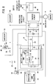
- the hybrid vehicle control device 10A according to the first embodiment (hereinafter also referred to as the control device 10A according to the first embodiment) will be described with reference to FIGS. 1 to 7B .
- the control device 10A according to the first embodiment shown in FIG. 1 is applied to a hybrid vehicle 12.
- the hybrid vehicle 12 is a straddle-type vehicle (motorcycle).
- the hybrid vehicle 12 supplies power to an AC generator 14 (driving electric motor), a first battery 16 of high voltage (for example, 48 V system) for supplying electric power to the AC generator 14, and a second battery 22 of a low voltage (for example, 12 V system) for supplying electric power to a plurality of accessories 18, 20, and an engine 24 to be started by driving of the AC generator 14.
- an AC generator 14 driving electric motor
- a first battery 16 of high voltage for example, 48 V system
- a second battery 22 of a low voltage for example, 12 V system
- the first battery 16 is a main battery and the second battery 22 is an auxiliary battery. Further, the ECU 26 (control unit) is responsible for drive control of the AC generator 14 and start control of the engine 24.
- the first battery 16 may be, for example, a Li ion battery, a Ni-MH battery, or a Ni-Cd battery.
- the second battery 22 may be, for example, a Pb battery.
- the first battery 16 and the battery management unit (BMU) 28 form a battery pack 30 together.
- the BMU 28 monitors the state of the first battery 16, and has an FET circuit 32 including an FET and a diode (not shown).
- the BMU 28 and the ECU 26 are connected in parallel to the first battery 16, and the FET circuit 32 is connected to the positive electrode side of the first battery 16.
- the negative electrode side of the first battery 16 is grounded via a resistor 34.
- Signals can be transmitted and received between the BMU 28 and the ECU 26 via the CAN communication line 36. Therefore, the BMU 28 can notify the ECU 26 of the state of charge (remaining capacity, voltage value) of the first battery 16 via the CAN communication line 36.
- a main switch 38 is connected to the positive electrode side of the second battery 22. By turning on the main switch 38, a direct current voltage of 12 V is applied from the second battery 22 to the accessory 20, the ECU 26 and the BMU 28 via the main switch 38, and the accessory 20, the ECU 26 and the BMU 28 can be activated.
- the ECU 26 can monitor the DC voltage of the second battery 22.
- the second battery 22 is connected to the accessory 18 and the down regulator 44 having the converter 42 via the main relay 40.
- the second battery 22 is connected to the output side of the BMU 28 in the line 35 via the starter relay 46 and the diode 48 (backflow preventing unit).
- the main relay 40 has an electromagnetic coil 50 and a normally closed contact 52.
- the starter relay 46 also has an electromagnetic coil 54 and a normally open contact 56.
- the normally closed contact 52 connects the positive electrode side of the second battery 22 to the accessory 18 and the converter 42.
- One end of the electromagnetic coil 50 is grounded, and the other end is connected to the main switch 38.
- the normally open contact 56 connects the positive electrode side of the second battery 22 to the anode of the diode 48.
- the electromagnetic coil 54 connects the main switch 38 to the ECU 26.
- the normally closed contact 52 maintains the closed state.
- the DC voltage of the second battery 22 is applied to the accessory 18 via the normally closed contact 52, and the accessory 18 can be activated.
- the normally open contact 56 maintains the open state.
- the normally open contact 56 is switched to the closed state and the second battery 22 is connected to the ECU 26 via the normally open contact 56, the diode 48, and the line 35 to supply power.
- the diode 48 has the anode on the side of the second battery 22 and the cathode on the side of the first battery 16. This makes it possible to prevent current from flowing from the high voltage first battery 16 to the low voltage second battery 22.
- the anode side of the diode 48 is connected to the ECU 26, and the voltage applied to the anode side can be monitored by the ECU 26.
- the positive electrode side is connected to the line 35, and the negative electrode side is grounded. Therefore, the converter 42 steps down the voltage of the line 35 (the DC voltage of the first battery 16), supplies the stepped down voltage to the first battery 16 or the accessory 18 via the normally closed contact 52 of the main relay 40. As a result, it is possible to charge the first battery 16 or drive the accessory 18. Further, the down regulator 44 is connected to the ECU 26, making it possible for the ECU 26 to monitor the down regulator 44.
- a voltage sensor 58 detects the voltage (the voltage of the capacitor 60 in FIG. 1 ) in the ECU 26.
- a voltage sensor 58 in the BMU 28.
- a voltage sensor 58 may be provided in the BMU 28, or a voltage sensor 58 may be provided in both the ECU 26 and the BMU 28.
- a voltage sensor 58 may be connected between the line 35 and the ground and the voltage in the ECU 26 (the voltage of the capacitor 60) may be detected via the line 35.
- the BMU 28 can notify the ECU 26 of the voltage value detected by the voltage sensor 58 via the CAN communication line 36.
- the voltage sensor 58 is provided in the ECU 26 will be described.
- the inverter circuit 64 includes six FETs (not shown) and forms a three-phase full-wave rectification circuit in which a parasitic diode is formed between the source terminal and the drain terminal of each FET.
- the AC generator 14 which is a three-phase brushless motor generator
- the DC voltage supplied from the first battery 16 is converted into three-phase AC power
- the converted three-phase AC power is supplied to the AC generator 14 to drive it as a motor. Thereby, it is possible to start the engine 24 or assist the driving force of the engine 24.
- the AC generator 14 functions as a generator, the kinetic energy is converted into three-phase AC power, and the three-phase AC power is converted into a DC voltage by the inverter circuit 64.
- the converted DC voltage is smoothed by the capacitor 60 and charged in the first battery 16.
- the ECU 26 performs drive control of the AC generator 14 by switching control of each FET at a predetermined duty ratio.
- the ECU 26 includes a startability determination unit 66.
- the startability determination unit 66 determines whether the remaining capacity of the first battery 16 notified from the BMU 28 via the CAN communication line 36 is such a capacity that the AC generator 14 cannot be driven (start the engine 24). Then, if the startability determination unit 66 determines that the current remaining capacity of the first battery 16 is not enough to start the engine 24, the ECU 26 supplies power from the second battery 22 to the ECU 26 to start the engine 24.
- the capacity of the first battery 16 varies according to the temperature of the first battery 16. Therefore, actually, the temperature of the first battery 16 is detected by a temperature sensor (not shown), and the startability determination unit 66 judges whether or not the remaining capacity of the first battery 16 is the capacity necessary for starting the engine 24 at the temperature. In the following description, it is assumed that the startability determination unit 66 determines whether or not the remaining capacity of the first battery 16 is the capacity necessary for starting the engine 24, in consideration of the temperature of the first battery 16.
- the startability determination unit 66 in the BMU 28. That is, since the BMU 28 monitors the state of the first battery 16, the startability determination unit 66 may be provided in the BMU 28, and determine whether the remaining capacity of the first battery 16 is the capacity required for starting the engine 24 also inside the BMU 28. In this case, the BMU 28 notifies the ECU 26 of the determination result of the startability determination unit 66 via the CAN communication line 36. In the following description, a case where the startability determination unit 66 is provided in the ECU 26 will be described.
- the startability determination unit 66 may monitor not only the remaining capacity of the first battery 16 but also the remaining capacity of the second battery 22, and determine whether the remaining capacity of the first battery 16 or the second battery 22 is the capacity required for starting the engine 24.
- the voltage value and the current value of the second battery 22 are respectively detected by a voltage sensor and a current sensor (not shown), and the startability determination unit 66 may calculate the remaining capacity of the second battery 22 from the detected voltage value and current value, and perform the above determination processing on the second battery 22.
- the determination processing by the startability determination unit 66 is not limited to the determination processing on the remaining capacity of the first battery 16 or the second battery 22.
- the startability determination unit 66 may determine whether the state of the first battery 16 or the second battery 22 is ready to start the engine 24. That is, in addition to the above-described remaining capacity, the startability determination unit 66 determines, for example, a determination processing on the voltage value of the first battery 16 or the second battery 22, or the failed state of the first battery 16 or the second battery 22.
- the BMU 28 detects the voltage value of the first battery 16, detects the occurrence of the failed state of the first battery 16, outputs the detection result of the detected voltage value and the occurrence of the failed state, and notifies the ECU 26 via the CAN communication line 36.
- the startability determination unit 66 determines whether or not the voltage value of the first battery 16 or the second battery 22 is lower than a predetermined set value. If the voltage value of one battery is lower than the set value, it is decided to start the engine 24 by the other battery.
- the predetermined set value is, for example, a battery voltage value sufficient to start the engine 24.
- the startability determination unit 66 determines whether the first battery 16 or the second battery 22 is in the failed state. If one battery is in the failed state, it is decided to start the engine 24 by the other battery.
- startability determination unit 66 carries out the determination processing on whether or not the remaining capacity of the first battery 16 is the capacity necessary for starting the engine 24.
- the ECU 26 instructs the BMU 28 to turn off the FET of the FET circuit 32 via the CAN communication line 36. As a result, the FET is turned off, and power supply from the first battery 16 to the ECU 26 is cut off.
- the voltage sensor 58 detects the voltage of the capacitor 60. As described above, the charge due to the DC voltage of the first battery 16 accumulated in the AC generator 14 is also accumulated in the capacitor 60. Therefore, the voltage of the capacitor 60 can be regarded as a voltage corresponding to the accumulated charge.
- the ECU 26 determines whether or not the voltage value of the voltage detected by the voltage sensor 58 is lower than the voltage value at the time when the electric charge is sufficiently discharged by the discharging unit 70 (sufficiently low enough to supply power by the second battery 22 Voltage value) or not is monitored. If it is determined that the electric charge has been sufficiently discharged, the ECU 26 supplies an excitation signal to the electromagnetic coil 54. Thereby, the normally open contact 56 is closed, and electric power can be supplied from the second battery 22 to the ECU 26 via the normally open contact 56, the diode 48, and the line 35. By supplying power from the second battery 22 as such, the AC generator 14 is driven to start the engine 24.
- the discharging unit 70 may be constructed as shown in FIGS. 2 and 3 .
- FIG. 2 shows a case where the resistor 72 is connected to the output side (ECU 26 side) of the BMU 28, and
- FIG. 3 shows a case where the resistor 74 is connected in parallel to the capacitor 60 in the ECU 26.
- the CR circuit of the capacitor 60 and the resistors 72, 74 can promptly discharge the charge due to the DC voltage of the first battery 16. The charge is discharged along the path indicated by the arrow, in FIGS. 2 and 3 .
- a circuit element used for purposes other than discharging may also be used to discharge the electric charge instead of the discharging unit 70.
- the electric charges may be consumed by using resistors or loads (not shown) or may be discharged via a line that directly connects the ECU 26 and the down regulator 44.
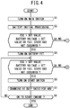
- the control device 10A according to the first embodiment is configured as described above. Next, the operation of the control device 10A will be described with reference to FIGS. 4 to 7B . This operation explanation will be described with reference to FIGS. 1 to 3 as necessary.
- control device 10A from when the driver of the hybrid vehicle 12 turns on the main switch 38 until when the engine 24 is started (cranked) will be described.
- step S1 when the driver turns on the main switch 38, power is supplied from the second battery 22 to the ECU 26, the BMU 28, and the accessory 20, and the ECU 26, the BMU 28, and the accessory 20 are activated.
- step S2 the BMU 28 detects the state of charge (remaining capacity, voltage value) of the first battery 16 and the occurrence of the failed state of the first battery 16 after executing the predetermined initial processing.
- the detection result of the remaining capacity (SOC), the voltage value, and the presence or absence of the occurrence of the failed state of the first battery 16 are notified from the BMU 28 to the ECU 26 via the CAN communication line 36.
- the BMU 28 constantly detects the state of charge or the occurrence of the failed state of the first battery 16, and sequentially notifies the ECU 26 via the CAN communication line 36.
- step S3 the startability determination unit 66 of the ECU 26 determines whether or not the notified remaining capacity (SOC) is larger than a predetermined setting value. Note that this set value corresponds to the remaining capacity of the first battery 16 when the first battery 16 cannot start the engine 24. Since the capacity of the first battery 16 varies depending on the temperature of the first battery 16, the startability determination unit 66 determines whether or not the notified SOC is larger than a set value corresponding to the current temperature of the first battery 16.
- SOC notified remaining capacity
- step S3 the startability determination unit 66 may determine whether the notified voltage value of the first battery 16 is higher than a predetermined set value.
- the set value in this case corresponds to the voltage value of the first battery 16 when the first battery 16 cannot start the engine 24. Further, in step S3, the startability determination unit 66 may determine whether the failed state of the first battery 16 has not occurred from the notified detection result.
- the startability determination unit 66 may perform any one of the above-described three determination processing, or may use a plurality of determination processing in combination.
- a description will be given of a case where one of the determination processing is executed by the startability determination unit 66.
- step S3 If it is determined in step S3 that the notified remaining capacity is greater than the set value, if the notified voltage value is higher than the set value or if the failed state has not occurred (step S3: YES), the startability determination unit 66 determines that the engine 24 can be started up under the current remaining capacity of the first battery 16, the current voltage value of the first battery 16, or the current state of the first battery 16. As a result, in the next step S4, the ECU 26 instructs the BMU 28 to turn on the FET of the FET circuit 32 via the CAN communication line 36. Upon receipt of a command from the ECU 26, the BMU 28 turns on the FET of the FET circuit 32. As a result, the first battery 16 can supply electric power to the ECU 26 via the FET circuit 32 and the line 35.
- the startability determination unit 66 judges again whether the notified remaining capacity (SOC) is larger than the set value, whether the notified voltage value is higher than the set value, or from the notified detection result, whether the failed state of the first battery 16 has not occurred from the notified detection result.
- SOC notified remaining capacity
- the notified voltage value is higher than the set value or when the failed state of the first battery 16 has not occurred (step S5: YES)
- the ECU 26 determines that the engine 24 can be started under the current remaining capacity of the first battery 16, the current voltage value of the first battery 16, or the current state of the first battery 16.
- step S7 when the driver turns on the start switch (not shown), in step S7, the ECU 26 drives the AC generator 14 with the electric power supplied from the first battery 16.
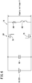
- FIG. 6 is a circuit diagram showing a simplified path from the first battery 16 (or the second battery 22) to the AC generator 14.
- a capacitor 60 is connected in parallel to the first battery 16.
- a series circuit of a resistor 80 and a coil 82 that simulates the AC generator 14 is connected in parallel to the capacitor 60 via the FETs 76 and 78 constituting the inverter circuit 64.
- step S8 in FIG. 4 YES
- the processing by the control device 10A is completed.
- the control device 10A returns to the determination processing of step S5, and performs the processing in steps S6 and S7 again.
- step S3 determines that the notified remaining capacity is less than the set value, the notified voltage value is less than the set value, or the failed state of the first battery 16 has occurred (Step S3: NO)
- step S9 of FIG. 5 the startability determination unit 66 determines that the engine 24 cannot be started under the current remaining capacity of the first battery 16, the current voltage value of the first battery 16, or the current state of the first battery 16.
- the ECU 26 determines to start the engine 24 by the DC voltage of the second battery 22.
- step S10 the ECU 26 confirms with the BMU 28 via the CAN communication line 36 whether or not the FET of the FET circuit 32 is the off state. In this case, since the FET of the FET circuit 32 is held in the off state, the BMU 28 transmits a holding signal indicating that the FET is kept in the off state to the ECU 26 via the CAN communication line 36.
- step S12 when the driver turns on the start switch, in step S12, the ECU 26 supplies an excitation signal to the electromagnetic coil 54.
- the normally open contact 56 of the starter relay 46 is closed, so that the second battery 22 can supply electric power to the ECU 26 via the normally open contact 56, the diode 48, and the line 35.
- step S13 the ECU 26 drives the AC generator 14 by the electric power supplied from the second battery 22.
- the processing of step S13 will be described with reference to FIGS. 6 and 7B .
- step S14 YES in FIG. 5
- step S15 YES
- the processing of the control device 10A is completed.
- the control device 10A returns to step S11 and repeats the processing in steps S12 and S13.
- step S14 YES
- step S15 NO
- the control device 10A returns to step S11 and executes the processing of steps S12 and S13 again.
- step S5 of FIG. 4 in the case where the notified remaining capacity is less than the set value, the notified voltage value is less than the set value, or the failed state of the first battery 16 occurs (Step S5: NO), in step S16 of FIG. 5 , the startability determination unit 66 determines that the start of the engine 24 by the first battery 16 has been tried many times but the engine 24 cannot be started, and that the engine 24 cannot be started in the current remaining capacity of the one battery 16, the current voltage value of the first battery 16, or the current state of the first battery 16. In response to this determination result, the ECU 26 decides to start the engine 24 by the DC voltage of the second battery 22 instead of the first battery 16.
- the ECU 26 instructs the BMU 28 to switch the FET of the FET circuit 32 from on to off via the CAN communication line 36.
- the FET circuit 32 of the BMU 28 turns the FET from on to off, and cuts off the power supply from the first battery 16 to the ECU 26.
- the BMU 28 transmits a holding signal indicating that the FET is turned off and held in the off state, to the ECU 26 via the CAN communication line 36.
- the electric charge due to the DC voltage of the first battery 16 accumulated in the AC generator 14 is discharged via the discharging unit 70 shown in FIGS. 1 to 3 .
- the ECU 26 monitors whether or not the voltage value detected by the voltage sensor 58 has decreased to the voltage value at the time when the discharging unit 70 has sufficiently discharged the electric charge.
- the control device 10A executes the processing of steps S11 to S15.
- electric power is supplied from the second battery 22 to the ECU 26 via the normally open contact 56, the diode 48, and the line 35.
- the AC generator 14 can be driven to start the engine 24.
- the control device 10A according to the first embodiment includes a diode as a backflow prevention unit for preventing the current flowing from the first battery 16 from flowing back to the second battery 22 48.
- the first battery 16 is connected via the line 35 to the AC generator 14 as a driving electric motor, while the second battery 22 is connected to the line 35 via the diode 48.
- the first battery 16 and the second battery 22 have rated values of different DC voltages and power is supplied from the first battery 16 or the second battery 22 having different rated values to the AC generator 14 to start the engine 24.
- the engine 24 can be directly started by supplying electric power from the other battery to the AC generator 14 via the line 35.
- the diode 48 can prevent the current from the high voltage first battery 16 from flowing into the low voltage second battery 22 via the line 35.
- the first battery 16 and the second battery 22 have different rated voltage values.
- the second battery 22 is a battery (12 V battery) having a lower voltage than the first battery 16 (48 V battery).
- the average value (12 V) of the supply voltage from the first battery 16 to the AC generator 14 and the average value (12 V) of the supply voltage from the second battery 22 to the AC generator 14 are set based on the duty ratio for driving the AC generator 14. Further, the engine 24 is started by supplying power from the first battery 16 or the second battery 22 with different rated values to the AC generator 14.
- the engine 24 can be started. That is, when the first battery 16 is a high-voltage battery of 48 V type, a supply voltage with an average value of 12 V is supplied to the AC generator 14 at a duty ratio of 25%, and the engine 24 can be started. On the other hand, when the second battery 22 is a 12V low voltage battery, a supply voltage with an average value of 12 V is supplied to the AC generator 14 at a duty ratio of 100%, and the engine 24 can be started.
- control device 10A can start the engine 24 with a simple structure when starting the engine 24 with both the first battery 16 and the second battery 22 having rated values of different voltages. Further, it is not necessary to provide a dedicated driving electric motor even for a hybrid vehicle having two batteries with different rated voltages, and it is possible to use the same parts as those of a conventional internal combustion engine vehicle.
- control device 10A power is supplied to the AC generator 14 without boosting the second battery 22, and the engine 24 is started, and therefore power consumption of the second battery 22 is suppressed to start the engine 24
- control device 10A by controlling the duty ratio of the first battery 16, it is possible to use conventional components used in a vehicle having an internal combustion engine to a hybrid vehicle having two batteries with different voltage ratings. This makes it possible to achieve common parts between a hybrid vehicle having two batteries with different rated voltages and a vehicle having an internal combustion engine.
- the duty ratio is set to a fixed value.
- a supply voltage with an average value of 12 V may be supplied at a duty ratio between 20% and 30% from the first battery 16 to the AC generator 14.
- the allowable voltage of the AC generator 14 is set, for example, within the range of 12 V to 48 V, and a voltage may be supplied to the AC generator 14 from the first battery 16 at a duty ratio of 20% to 80% according to the state of the hybrid vehicle 12 such as an engine rotating speed and a vehicle speed, to drive the AC generator 14. Specifically, a voltage is supplied to the AC generator 14 from the first battery 16 at a duty ratio of 20% to 30%to start up the AC generator 14. Thereafter, when the engine 24 rotates at high speed while the hybrid vehicle 12 is traveling, a voltage is supplied from the first battery 16 to the AC generator 14 at a duty ratio of 20% to 80% that is higher than that at the starting time, the AC generator 14 is driven to assist the rotation of the crankshaft.
- the AC generator 14 may be driven by both the first battery 16, which is a high voltage battery of 48 V type, and the second battery 22 which is a low voltage battery of 12 V type.
- control device 10A can also obtain the following effects. That is, the control device 10A includes a startability determination unit 66 that determines whether or not the state of the first battery 16 or the second battery 22 is in a state capable of starting the engine 24, and in the case where the startability determination unit 66 determines that one of the batteries cannot start the engine 24, the other battery supplies electric power to the AC generator 14 to start the engine 24.
- a startability determination unit 66 that determines whether or not the state of the first battery 16 or the second battery 22 is in a state capable of starting the engine 24, and in the case where the startability determination unit 66 determines that one of the batteries cannot start the engine 24, the other battery supplies electric power to the AC generator 14 to start the engine 24.
- the startability determination unit 66 determines that one of the batteries cannot start the engine 24, the engine 24 is started by the other battery. Therefore, even if the engine 24 cannot be started due to the condition of the one of the batteries, it is possible to start the engine 24 by supplying electric power from the other battery to the AC generator 14.
- the start / unavailability determination unit 66 determines that the engine 24 cannot be started, and the engine 24 is started with the other battery. Therefore, even when one of the batteries cannot start the engine 24 due to the reduced power or failed state, the engine 24 can be started by supplying power from the other battery to the AC generator 14.
- the second battery 22 is a battery having a voltage lower than that of the first battery 16, and in the normal state, to start the engine 24 the first battery 16 supplies electric power to the AC generator 14 in preference to the second battery 22, On the other hand, if the startability determination unit 66 determines that the first battery 16 cannot start the engine 24, the second battery 22 supplies electric power to the AC generator 14 to start the engine 24.
- the average value (12 V) of the supply voltage from the first battery 16 to the AC generator 14 and the average value (12 V) of the supply voltage from the second battery 22 to the AC generator 14 are determined based on the duty ratio for driving the AC generator 14.
- the engine 24 can be started even with batteries having rated values of different DC voltages. That is, when the first battery 16 is a high-voltage battery of 48 V type, a supply voltage with an average value of 12 V is supplied to the AC generator 14 at a duty ratio of 25%, and the engine 24 can be started. On the other hand, when the second battery 22 is a 12V low voltage battery, a supply voltage with an average value of 12 V is supplied to the AC generator 14 at a duty ratio of 100%, and the engine 24 can be started.
- control device 10A further includes a diode 48 as a backflow preventing unit for preventing the current flowing from the first battery 16 from flowing back to the second battery 22. Thereby, it is possible to prevent the current from the high voltage first battery 16 from flowing into the low voltage second battery 22.
- the control device 10A further includes a discharging unit 70 for discharging the electric charge caused by the DC voltage of the first battery 16 accumulated in the AC generator 14. Even if the rated values of the DC voltages differ between the first battery 16 and the second battery 22, by discharging the electric charge in the AC generator 14 due to the first battery 16 by the discharging unit 70, it is possible to start the engine 24 by supplying electric power from the second battery 22 to the AC generator 14.
- the control device 10A further includes a voltage sensor 58 as detection unit for checking whether the electric charge has been discharged by the discharging unit 70.
- a voltage sensor 58 as detection unit for checking whether the electric charge has been discharged by the discharging unit 70.
- the control device 10A further includes an ECU 26 that drives and controls the AC generator 14 and a BMU 28 that monitors the state of the first battery 16, and the voltage sensor 58 is provided in the ECU 26 or the BMU 28.
- a control device 10B according to a second embodiment will be described with reference to FIG. 8 .
- the same components as those of the control device 10A (see FIGS. 1 to 7B ) according to the first embodiment are denoted by the same reference numerals, the detailed description thereof will be omitted.
- the control device 10B is different from the control device 10A in that the positive electrode side of the second battery 22 is connected to the line 35 via the transfer relay 84 and the FET 86 in the BMU 28.
- the transfer relay 84 has a changeover contact 88 and an electromagnetic coil 90.
- the changeover contact 88 connects the second battery 22 and the FET 86.
- the electromagnetic coil 90 connects the main switch 38 and the ECU 26.
- the control device 10B when an excitation signal is supplied from the ECU 26 to the electromagnetic coil 90, the second battery 22 and the FET 86 are connected by the changeover contact 88.
- the BMU 28 turns on the FET 86 according to this command.
- electric power can be supplied from the second battery 22 to the ECU 26 via the changeover contact 88, the FET 86 and the line 35.
- the control device 10B As described above, also in the control device 10B according to the second embodiment, by supplying power from the second battery 22 to the ECU 26 and driving the AC generator 14, the engine 24 can be started. As a result, also in the control device 10B, the effect of the control device 10A according to the first embodiment can be easily obtained. Further, by interposing the FET 86 between the second battery 22 and the line 35, the FET 86 functions as a backflow prevention unit similarly to the above-described diode 48 (see FIGS. 1 to 3 ). Since the diode 92 is connected in parallel to the FET 86, it is also possible to make the diode 92 function as a backflow prevention unit.
- a control device 10C according to a third embodiment will be described with reference to FIG. 9 .
- the control device 10C is different from the control device 10B (see FIG. 8 ) according to the second embodiment in that the FET 86 is disposed in the ECU 26.
- the FET 86 is connected to a portion near the voltage sensor 58 and the capacitor 60 in the line 35 in the ECU 26.
- the control device 10C by supplying electric power from the second battery 22 to the AC generator 14 via the changeover contact 88, the FET 86 and the line 35, the AC generator 14 is driven to start the engine 24. Therefore, also in the control device 10C, the respective effects of the control devices 10A, 10B according to the first and second embodiments can be easily obtained.
- a control device 10D according to a fourth embodiment will be described with reference to FIG. 10 .
- the control device 10D is different from the control devices 10A to 10C (see FIGS. 1 to 9 ) according to the first to third embodiments in that the diode 48 as a backflow prevention unit is disposed in the down regulator 44.
- the anode of the diode 48 is connected to the changeover contact 88 of the transfer relay 84 and the cathode is connected in the down regulator 44 to the line 94 connecting between the converter 42 and the line 35.
- control device 10D power is supplied from the second battery 22 to the ECU 26 via the changeover contact 88, the diode 48, and the lines 94 and 35. Even in this case, electric power from the second battery 22 is supplied to the AC generator 14, the AC generator 14 is driven, and the engine 24 can be started. Thus, the respective effects of the control devices 10A to 10C according to the first to third embodiments can be easily obtained.
- control device 10E according to a fifth embodiment will be described with reference to FIG. 11 .
- control device 10E the positive electrode side of the second battery 22 is connected to the line 35 via two transfer relays 96a, 96b.
- the control device 10E is different from the control devices 10A to 10D (see FIGS. 1 to 10 ) in that the transfer relays 96a, 96b function as a backflow prevention unit like the aforementioned diode 48 ( FIGS. 1 to 3 and 10 ) according to the first to fourth embodiments.
- the transfer relays 96a, 96b have the same structure as the above-described transfer relay 84 (see FIGS. 8 to 10 ), and have changeover contacts 98a, 98b and electromagnetic coils 100a and 100b, respectively. In this case, the transfer relay 96a and the transfer relay 96b are sequentially connected from the second battery 22 to the line 35.
- the changeover contact 98a connects between the second battery 22 and the changeover contact 98b of the transfer relay 96b. Further, the electromagnetic coil 100a connects the main switch 38 and the ECU 26. On the other hand, in the transfer relay 96b, the changeover contact 98b connects the changeover contact 98a of the transfer relay 96a and the line 35. Further, the electromagnetic coil 100b connects the main switch 38 and the ECU 26.
- the second battery 22 and the changeover contact 98b of the transfer relay 96b are connected by the changeover contact 98a.
- the changeover contact 98b connects the changeover contact 98a of the transfer relay 96a and the line 35.
- the second battery 22 can supply electric power to the ECU 26 via the changeover contacts 98a, 98b and the line 35. As a result, it is possible to drive the AC generator 14 and start the engine 24.
- control device 10E since the two transfer relays 96a and 96b function as backflow prevention unit like the diodes 48, the effects of the control devices 10A to 10D according to the first to fourth embodiments can be easily obtained.
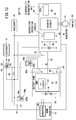
- a control device 10F according to a sixth embodiment will be described with reference to FIG. 12 .
- the control device 10F is different from the control device 10E (see FIG. 11 ) according to the fifth embodiment in that the electromagnetic coil 100b constituting the transfer relay 96b on the line 35 side connects the main switch 38 and the battery pack 30.
- the changeover contact 98b connects the changeover contact 98a of the transfer relay 96a and the line 35.
- the second battery 22 supplies electric power to the ECU 26 via the changeover contacts 98a, 98b and the line 35, and drives the AC generator 14 to start the engine 24.
- control device 10F according to the sixth embodiment effects similar to those of the control device 10E according to the fifth embodiment can be easily obtained.
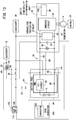
- a control device 10G according to a seventh embodiment will be described with reference to FIG. 13 .
- the control device 10G is different from the control devices 10A to 10F (see FIGS. 1 to 12 ) according to the first to six embodiments in that, in place of the down regulator 44, the starter relay 46, and the diode 48 (see FIGS. 1 to 3 ), the DC/DC converter 106 having the transfer relay 102 and the converter 104 are disposed.
- the transfer relay 102 has a changeover contact 108 and an electromagnetic coil 110.
- the changeover contact 108 connects the second battery 22 and the converter 104.
- the electromagnetic coil 110 connects the main switch 38 and the ECU 26.
- the DC/DC converter 106 is a buck-boost converter that boosts the DC voltage (12 V) of the second battery 22 to a high voltage of 48 V while stepping down the high voltage of 48 V to 12 V.
- the DC/DC converter 106 is disposed in place of the above-described down regulator 44.
- an excitation signal is supplied from the ECU 26 to the electromagnetic coil 110, and the second battery 22 and the converter 104 are connected to each other through the changeover contact 108, whereby the second battery 22 supplies a DC voltage of 12 V to the converter 104 via the changeover contact 108.
- the converter 104 boosts 12 V to 48 V (the same voltage value as the DC voltage of the first battery 16) and supplies the boosted DC voltage to the ECU 26 via the lines 94, 35.
- the AC generator 14 can be driven with the power corresponding to the DC voltage of 48 V, and the engine 24 can be started.
- the converter 104 boosts the DC voltage of the second battery 22 and supplies power corresponding to the boosted DC voltage to the AC generator 14.
- the AC generator 14 can be driven and the engine 24 can be started similarly to the case where the AC generator 14 is driven by the electric power of the first battery 16.
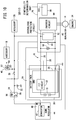
- a control device 10H according to an eighth embodiment will be described with reference to FIG. 14 .
- the eighth embodiment shows a case where electric power is supplied from the outside to the AC generator 14 to drive the AC generator 14 to start the engine 24.
- This embodiment is applicable to the case where, for example, the engine 24 is started using an external battery because the remaining capacity of the second battery 22 is small in spite of an attempt to start the engine 24 by the second battery 22 in place of the first battery 16.
- the hybrid vehicle 12 is provided with an external connection terminal 112 (external power supply unit), and the external connection terminal 112 is connected to the inverter circuit 64 via a diode 114 in the ECU 26.
- the second battery 22 and the external connection terminal 112 constitute the second battery unit 116.
- the external connection terminal 112 may be an external power connection portion such as a terminal block provided in the peripheral circuit of the second battery 22. Therefore, the external connection terminal 112 is provided separately from the terminal of the second battery 22.
- the diode 114 functions as a reverse current preventing unit similarly to the above-described diode 48 (see FIGS. 1 to 3 ).
- the battery 120 of the other vehicle 118 its positive electrode side is connected to the external connection terminal 112 via the booster cable 122, and the negative electrode side of the battery 120 is grounded.
- the AC generator 14 can be driven with the supplied electric power to start the engine 24.
- the engine 24 can be started by the external battery 120 (external power).
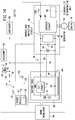
- a control device 10I according to a ninth embodiment will be described with reference to FIG. 15 .
- the control device 10I according to the ninth embodiment is different from the control device 10H (see
- FIG. 14 according to the eighth embodiment in that a diode 114 connected to the external connection terminal 112 is disposed in the BMU 28.
- the anode of the diode 114 is connected to the external connection terminal 112, and the cathode is connected to the line 35.
- the positive electrode side of the battery 120 of the other vehicle 118 is connected to the external connection terminal 112 via the booster cable 122, and the negative electrode side of the battery 120 is grounded. Even in this case, if the remaining capacity of the second battery 22 is small, electric power can be supplied from the battery 120 to the ECU 26 via the booster cable 122, the external connection terminal 112, the diode 114, and the line 35. As a result, the AC generator 14 can be driven with the supplied electric power to start the engine 24.
- the control device 10I according to the ninth embodiment also has the same advantages as the control device 10H according to the eighth embodiment.
Abstract
Description
- The present invention relates to a control device for a hybrid vehicle that starts an engine by supplying electric power from a first battery to a driving electric motor while supplying electric power from a second battery to a plurality of accessories.
- In a conventional hybrid vehicle, an engine is started by supplying power from a main battery of high voltage (for example, 48 V system) to an auxiliary motor. On the other hand, in the case of starting the engine at times when the electric power of the main battery is reduced, there are known a method of increasing the voltage of the auxiliary battery of a low voltage (for example, 12 V system) to charge the main battery (see Japanese Laid-Open Patent Publication No.
2009-154847 - As described above, in the conventional technology, it is necessary to provide a step-up converter in order to step up the voltage of the auxiliary battery, or it is necessary to provide a starter motor separate from the auxiliary motor. As a result, the cost becomes high, and a space for installing parts is required.
- Accordingly, the present invention provides a hybrid vehicle control device for a hybrid vehicle having an engine and a driving electric motor for assisting the engine, wherein when one of the batteries (main battery) is reduced in power, the driving electric motor is driven and controlled by a voltage of another battery (auxiliary battery) to start the engine.
- The hybrid vehicle control device according to the present invention includes a driving electric motor, a first battery that supplies power to the driving electric motor, and a second battery that supplies power to a plurality of accessories, wherein the driving electric motor starts the engine. The hybrid vehicle control device has the following features.
- First feature: The control device further includes a backflow prevention unit configured to prevent current flowing from the first battery from flowing back to the second battery. In this case, the first battery is connected to the driving electric motor via a line, while the second battery is connected to the line via the backflow prevention unit. The first battery and the second battery have different rated voltages. The engine is started by power supplied from the first battery or the second battery having different the rated values.
- Second feature: The first battery and the second battery have different rated voltage values. In this case, the second battery is a battery having a lower voltage than the first battery. The average value of the supply voltage from the first battery to the driving electric motor and the average value of the supply voltage from the second battery to the driving electric motor are determined to a duty ratio for driving the driving electric motor. Further, the engine is started by supplying electric power from the first battery or the second battery different in the rated value to the driving electric motor.
- Third feature: The control device further includes a startability determination unit for determining whether the state of the first battery or the second battery is in a state where the engine can be started. When the startability determination unit determines that one of the batteries cannot start the engine, electric power is supplied from another battery to the driving electric motor to start the engine.
- Fourth feature: The startability determination unit determines whether the remaining capacity of the first battery or the second battery is a capacity required for starting the engine, the voltage value of the first battery or the second battery is lower than a predetermined set value, or the first battery or the second battery is in a failed state. Then, if the one of the batteries is determined not to be able to start the engine based on any one of following conditions that the remaining capacity of one of the batteries is lower than the required capacity, the voltage value of the one of the batteries is lower than the set value, and the one of the batteries is in the failed state, the startability determination unit starts the engine with the other battery.
- Fifth feature: The second battery is a battery having a voltage lower than that of the first battery, and the first battery supplies electric power to the driving electric motor in preference to the second battery to start the engine in a normal state. When the startability determination unit determines that the engine cannot be started by the first battery, the control device supplies electric power from the second battery to the driving electric motor to start the engine.
- Sixth feature: In the first feature, the average value of the supply voltage from the first battery to the driving electric motor and the average value of the supply voltage from the second battery to the driving electric motor are determined based on the duty ratio for driving the driving electric motor.
- Seventh feature: In the second feature, the control device further includes a backflow prevention unit for preventing current flowing from the first battery from flowing back to the second battery.
- Eighth feature: The control device further includes permission startability determination unit for determining whether the first battery or the second battery is in a state capable of starting the engine, and a discharging unit for discharging the electric charge caused by the voltage of the first battery accumulated in the driving electric motor, when the startability determination unit judges that the first battery cannot start the engine.
- Ninth feature: The control device further includes a detection unit for checking whether or not the electric charge has been discharged by the discharging unit.
- Tenth feature: The control device may further include a control unit that drives and controls the driving electric motor; and a battery management unit that monitors a state of the first battery, wherein the detecting unit is equipped in the control unit and the battery management unit.
- Eleventh feature: A second battery unit is formed of the second battery and the peripheral circuit of the second battery, and the second battery unit is provided with an external power supply unit configured to be supplied with external electric power to the driving electric motor separately from a terminal of the second battery.
- According to the first feature of the present invention, when one of the batteries is reduced in power, power is supplied from the other battery to the driving electric motor via the line, so that the engine is directly started. This eliminates the necessity of providing a boost converter for boosting the voltage of the auxiliary battery and a starter motor separately from the auxiliary motor which are required in the conventional art. As a result, space saving of the control device can be realized while suppressing cost. Further, by the backflow prevention unit, it is possible to prevent the current from the high voltage battery from flowing into the low voltage battery via the line.
- According to the second feature of the present invention, it is possible to suppress the frequency of starting the engine with the second battery of the low voltage by prioritizing the starting of the engine by the high voltage first battery. As a result, it is possible to avoid the second battery from running out. On the other hand, if the first battery is reduced in power, the engine can be started by supplying electric power from the second battery to the driving electric motor.
- Further, by driving the driving electric motor by the duty ratio, it is possible to start the engine even with a battery having a different rated voltage value. For example, when the first battery is a 48V high-voltage battery, a supply voltage (average value) of 12 V is supplied to the driving electric motor at a duty ratio of 25%, and the engine can be started. On the other hand, when the second battery is a 12V low-voltage battery, a supply voltage (average value) of 12 V is supplied to the driving electric motor at a duty ratio of 100%, and the engine can be started.
- According to the third feature of the present invention, when the startability determination unit determines that one of the batteries cannot start the engine, the engine is started by the other battery. As a result, even if the engine cannot be started due to the state of one of the batteries, it is possible to start the engine by supplying electric power from the other battery to the driving electric motor.
- According to the fourth feature of the present invention, for one battery, if the remaining capacity is less than the required capacity, the voltage value is lower than the set value, or it is in the failed state, the startability determination unit determines that one of the batteries cannot start the engine, and starts the engine with the other battery. Therefore, even if one of the batteries cannot start the engine due to the reduced power or failed state, it is possible to start the engine by supplying electric power from the other battery to the driving electric motor.
- According to the fifth feature of the present invention, by prioritizing the starting of the engine using the high voltage first battery, it is possible to suppress the frequency of starting the engine using the low voltage second battery. As a result, it is possible to avoid the second battery from running out. On the other hand, if the first battery is reduced in power, the engine can be started by supplying electric power from the second battery to the driving electric motor.
- According to the sixth feature of the present invention, similarly to the second feature, by driving the driving electric motor by the duty ratio, it is possible to start the engine even with a battery having a different rated voltage value.
- According to the seventh feature of the present invention, similarly to the first feature, it is possible to prevent the current from the high voltage first battery from flowing into the low voltage second battery by the backflow prevention unit.
- According to the eighth feature of the present invention, even if the rated voltages are different between the first battery and the second battery by the discharging unit emitting the electric charge caused by the voltage of the first battery from inside the driving electric motor, it is possible to start the engine by supplying electric power from the second battery to the driving electric motor after the emission of electric charge.
- According to the ninth feature of the present invention, it is possible to prevent unintentional application of different voltages to the driving electric motor by using the detection unit.
- According to the tenth feature of the present invention, there is no need to provide an independent voltage supply unit externally for driving the detection unit. Thus, there is no need to provide a harness or the like for taking in the detection result of the detection unit, and it is possible to reduce the number of parts.
- According to the eleventh feature of the present invention, even when the second battery is reduced in power, it is possible to start the engine by supplying the external electric power to the driving electric motor.
-
-
FIG. 1 is a circuit diagram of a hybrid vehicle including a control device according to a first embodiment; -
FIG. 2 is a circuit diagram in which a part of the control device inFIG. 1 is modified; -
FIG. 3 is a circuit diagram in which a part of the control device inFIG. 1 is modified; -
FIG. 4 is a flowchart for explaining an engine starting operation by the control device ofFIGS. 1 to 3 ; -
FIG. 5 is a flowchart for explaining a starting operation of an engine by the control device ofFIGS. 1 to 3 ; -
FIG. 6 is a simplified circuit diagram for explaining a PWM operation; -
FIG. 7A is a timing chart when the duty ratio is 25% at 48V start; -
FIG. 7B is a timing chart when the duty ratio is 100% at 12V start; -
FIG. 8 is a circuit diagram of a hybrid vehicle including a control device according to a second embodiment; -
FIG. 9 is a circuit diagram of a hybrid vehicle including a control device according to a third embodiment; -
FIG. 10 is a circuit diagram of a hybrid vehicle including a control device according to a fourth embodiment; -
FIG. 11 is a circuit diagram of a hybrid vehicle including a control device according to a fifth embodiment; -
FIG. 12 is a circuit diagram of a hybrid vehicle including a control device according to a sixth embodiment; -
FIG. 13 is a circuit diagram of a hybrid vehicle including a control device according to a seventh embodiment; -
FIG. 14 is a circuit diagram of a hybrid vehicle including a control device according to an eighth embodiment; and -
FIG. 15 is a circuit diagram of a hybrid vehicle including a control device according to a ninth embodiment. - The present invention will be described in detail below with preferred embodiments with reference to the accompanying drawings.
- The hybrid
vehicle control device 10A according to the first embodiment (hereinafter also referred to as thecontrol device 10A according to the first embodiment) will be described with reference toFIGS. 1 to 7B . - The
control device 10A according to the first embodiment shown inFIG. 1 is applied to ahybrid vehicle 12. In the first embodiment, thehybrid vehicle 12 is a straddle-type vehicle (motorcycle). - The
hybrid vehicle 12 supplies power to an AC generator 14 (driving electric motor), afirst battery 16 of high voltage (for example, 48 V system) for supplying electric power to theAC generator 14, and asecond battery 22 of a low voltage (for example, 12 V system) for supplying electric power to a plurality ofaccessories engine 24 to be started by driving of theAC generator 14. - The
first battery 16 is a main battery and thesecond battery 22 is an auxiliary battery. Further, the ECU 26 (control unit) is responsible for drive control of theAC generator 14 and start control of theengine 24. Thefirst battery 16 may be, for example, a Li ion battery, a Ni-MH battery, or a Ni-Cd battery. Further, thesecond battery 22 may be, for example, a Pb battery. - In the
control device 10A, thefirst battery 16 and the battery management unit (BMU) 28 form abattery pack 30 together. TheBMU 28 monitors the state of thefirst battery 16, and has anFET circuit 32 including an FET and a diode (not shown). In this case, theBMU 28 and theECU 26 are connected in parallel to thefirst battery 16, and theFET circuit 32 is connected to the positive electrode side of thefirst battery 16. The negative electrode side of thefirst battery 16 is grounded via aresistor 34. By turning on the FET of theFET circuit 32, electric power of thefirst battery 16 can be supplied from thefirst battery 16 to theECU 26 through theFET circuit 32 and theline 35 on the positive electrode side. Signals can be transmitted and received between theBMU 28 and theECU 26 via theCAN communication line 36. Therefore, theBMU 28 can notify theECU 26 of the state of charge (remaining capacity, voltage value) of thefirst battery 16 via theCAN communication line 36. - A
main switch 38 is connected to the positive electrode side of thesecond battery 22. By turning on themain switch 38, a direct current voltage of 12 V is applied from thesecond battery 22 to theaccessory 20, theECU 26 and theBMU 28 via themain switch 38, and theaccessory 20, theECU 26 and theBMU 28 can be activated. TheECU 26 can monitor the DC voltage of thesecond battery 22. - The
second battery 22 is connected to theaccessory 18 and thedown regulator 44 having theconverter 42 via themain relay 40. In addition, thesecond battery 22 is connected to the output side of theBMU 28 in theline 35 via thestarter relay 46 and the diode 48 (backflow preventing unit). - The
main relay 40 has anelectromagnetic coil 50 and a normally closedcontact 52. Thestarter relay 46 also has anelectromagnetic coil 54 and a normallyopen contact 56. The normally closedcontact 52 connects the positive electrode side of thesecond battery 22 to theaccessory 18 and theconverter 42. One end of theelectromagnetic coil 50 is grounded, and the other end is connected to themain switch 38. The normallyopen contact 56 connects the positive electrode side of thesecond battery 22 to the anode of thediode 48. Theelectromagnetic coil 54 connects themain switch 38 to theECU 26. - In this case, in a state where no voltage is applied to the
electromagnetic coil 50, the normally closedcontact 52 maintains the closed state. As a result, the DC voltage of thesecond battery 22 is applied to theaccessory 18 via the normally closedcontact 52, and the accessory 18 can be activated. - Further, in a state where no excitation signal is supplied from the
ECU 26 to theelectromagnetic coil 54, the normallyopen contact 56 maintains the open state. On the other hand, when an excitation signal is supplied from theECU 26 to theelectromagnetic coil 54, the normallyopen contact 56 is switched to the closed state and thesecond battery 22 is connected to theECU 26 via the normallyopen contact 56, thediode 48, and theline 35 to supply power. - The
diode 48 has the anode on the side of thesecond battery 22 and the cathode on the side of thefirst battery 16. This makes it possible to prevent current from flowing from the high voltagefirst battery 16 to the low voltagesecond battery 22. The anode side of thediode 48 is connected to theECU 26, and the voltage applied to the anode side can be monitored by theECU 26. - In the
converter 42 of thedown regulator 44, the positive electrode side is connected to theline 35, and the negative electrode side is grounded. Therefore, theconverter 42 steps down the voltage of the line 35 (the DC voltage of the first battery 16), supplies the stepped down voltage to thefirst battery 16 or theaccessory 18 via the normally closedcontact 52 of themain relay 40. As a result, it is possible to charge thefirst battery 16 or drive theaccessory 18. Further, thedown regulator 44 is connected to theECU 26, making it possible for theECU 26 to monitor thedown regulator 44. - In the
ECU 26, a voltage sensor 58 (detecting unit), acapacitor 60, anovervoltage protection circuit 62 and aninverter circuit 64 are connected in parallel to theBMU 28. Thevoltage sensor 58 detects the voltage (the voltage of thecapacitor 60 inFIG. 1 ) in theECU 26. - In the
control device 10A, it is also possible to provide avoltage sensor 58 in theBMU 28. In this case, instead of thevoltage sensor 58 in theECU 26, avoltage sensor 58 may be provided in theBMU 28, or avoltage sensor 58 may be provided in both theECU 26 and theBMU 28. In the case where thevoltage sensor 58 is provided in theBMU 28, for example, avoltage sensor 58 may be connected between theline 35 and the ground and the voltage in the ECU 26 (the voltage of the capacitor 60) may be detected via theline 35. Thereby, theBMU 28 can notify theECU 26 of the voltage value detected by thevoltage sensor 58 via theCAN communication line 36. In the following description, a case where thevoltage sensor 58 is provided in theECU 26 will be described. - The
inverter circuit 64 includes six FETs (not shown) and forms a three-phase full-wave rectification circuit in which a parasitic diode is formed between the source terminal and the drain terminal of each FET. In this case, when theAC generator 14, which is a three-phase brushless motor generator, is driven and controlled, the DC voltage supplied from thefirst battery 16 is converted into three-phase AC power, and the converted three-phase AC power is supplied to theAC generator 14 to drive it as a motor. Thereby, it is possible to start theengine 24 or assist the driving force of theengine 24. - On the other hand, at the time of regeneration, the
AC generator 14 functions as a generator, the kinetic energy is converted into three-phase AC power, and the three-phase AC power is converted into a DC voltage by theinverter circuit 64. The converted DC voltage is smoothed by thecapacitor 60 and charged in thefirst battery 16. - The
ECU 26 performs drive control of theAC generator 14 by switching control of each FET at a predetermined duty ratio. - Further, the
ECU 26 includes astartability determination unit 66. Thestartability determination unit 66 determines whether the remaining capacity of thefirst battery 16 notified from theBMU 28 via theCAN communication line 36 is such a capacity that theAC generator 14 cannot be driven (start the engine 24). Then, if thestartability determination unit 66 determines that the current remaining capacity of thefirst battery 16 is not enough to start theengine 24, theECU 26 supplies power from thesecond battery 22 to theECU 26 to start theengine 24. - In practice, the capacity of the
first battery 16 varies according to the temperature of thefirst battery 16. Therefore, actually, the temperature of thefirst battery 16 is detected by a temperature sensor (not shown), and thestartability determination unit 66 judges whether or not the remaining capacity of thefirst battery 16 is the capacity necessary for starting theengine 24 at the temperature. In the following description, it is assumed that thestartability determination unit 66 determines whether or not the remaining capacity of thefirst battery 16 is the capacity necessary for starting theengine 24, in consideration of the temperature of thefirst battery 16. - Further, in the
control device 10A, it is also possible to provide thestartability determination unit 66 in theBMU 28. That is, since theBMU 28 monitors the state of thefirst battery 16, thestartability determination unit 66 may be provided in theBMU 28, and determine whether the remaining capacity of thefirst battery 16 is the capacity required for starting theengine 24 also inside theBMU 28. In this case, theBMU 28 notifies theECU 26 of the determination result of thestartability determination unit 66 via theCAN communication line 36. In the following description, a case where thestartability determination unit 66 is provided in theECU 26 will be described. - Further, the
startability determination unit 66 may monitor not only the remaining capacity of thefirst battery 16 but also the remaining capacity of thesecond battery 22, and determine whether the remaining capacity of thefirst battery 16 or thesecond battery 22 is the capacity required for starting theengine 24. In this case, the voltage value and the current value of thesecond battery 22 are respectively detected by a voltage sensor and a current sensor (not shown), and thestartability determination unit 66 may calculate the remaining capacity of thesecond battery 22 from the detected voltage value and current value, and perform the above determination processing on thesecond battery 22. - In addition, the determination processing by the
startability determination unit 66 is not limited to the determination processing on the remaining capacity of thefirst battery 16 or thesecond battery 22. Thestartability determination unit 66 may determine whether the state of thefirst battery 16 or thesecond battery 22 is ready to start theengine 24. That is, in addition to the above-described remaining capacity, thestartability determination unit 66 determines, for example, a determination processing on the voltage value of thefirst battery 16 or thesecond battery 22, or the failed state of thefirst battery 16 or thesecond battery 22. - In this case, for example, the
BMU 28 detects the voltage value of thefirst battery 16, detects the occurrence of the failed state of thefirst battery 16, outputs the detection result of the detected voltage value and the occurrence of the failed state, and notifies theECU 26 via theCAN communication line 36. - In the determination processing for the voltage value of the
first battery 16 or thesecond battery 22, thestartability determination unit 66 determines whether or not the voltage value of thefirst battery 16 or thesecond battery 22 is lower than a predetermined set value. If the voltage value of one battery is lower than the set value, it is decided to start theengine 24 by the other battery. The predetermined set value is, for example, a battery voltage value sufficient to start theengine 24. - In the determination processing on the failed state of the
first battery 16 or thesecond battery 22, thestartability determination unit 66 determines whether thefirst battery 16 or thesecond battery 22 is in the failed state. If one battery is in the failed state, it is decided to start theengine 24 by the other battery. - In the following description, a description will be mainly given of the case where the
startability determination unit 66 carries out the determination processing on whether or not the remaining capacity of thefirst battery 16 is the capacity necessary for starting theengine 24. - Here, a case where the
engine 24 is started by supplying electric power from thesecond battery 22 to theECU 26 based on the judgment by thestartability determination unit 66 that theengine 24 cannot be started by thefirst battery 16 will be specifically described. First, theECU 26 instructs theBMU 28 to turn off the FET of theFET circuit 32 via theCAN communication line 36. As a result, the FET is turned off, and power supply from thefirst battery 16 to theECU 26 is cut off. - In this case, electric charge due to the DC voltage of the
first battery 16 is accumulated in theAC generator 14, and this charge is also accumulated in thecapacitor 60. The electric charge is discharged from theline 35 connecting theBMU 28 and theECU 26 via theconverter 42 as indicated by an arrow inFIG. 1 . That is, theline 35, theconverter 42, and the like function as the dischargingunit 70 for discharging the electric charge. The electric charge is charged from theconverter 42 to thesecond battery 22 via the normally closedcontact 52 of themain relay 40, or is consumed by theaccessory 18. - In the
ECU 26, thevoltage sensor 58 detects the voltage of thecapacitor 60. As described above, the charge due to the DC voltage of thefirst battery 16 accumulated in theAC generator 14 is also accumulated in thecapacitor 60. Therefore, the voltage of thecapacitor 60 can be regarded as a voltage corresponding to the accumulated charge. - Therefore, the
ECU 26 determines whether or not the voltage value of the voltage detected by thevoltage sensor 58 is lower than the voltage value at the time when the electric charge is sufficiently discharged by the discharging unit 70 (sufficiently low enough to supply power by thesecond battery 22 Voltage value) or not is monitored. If it is determined that the electric charge has been sufficiently discharged, theECU 26 supplies an excitation signal to theelectromagnetic coil 54. Thereby, the normallyopen contact 56 is closed, and electric power can be supplied from thesecond battery 22 to theECU 26 via the normallyopen contact 56, thediode 48, and theline 35. By supplying power from thesecond battery 22 as such, theAC generator 14 is driven to start theengine 24. - Instead of
FIG. 1 , the dischargingunit 70 may be constructed as shown inFIGS. 2 and3 .FIG. 2 shows a case where theresistor 72 is connected to the output side (ECU 26 side) of theBMU 28, andFIG. 3 shows a case where theresistor 74 is connected in parallel to thecapacitor 60 in theECU 26. In either case, the CR circuit of thecapacitor 60 and theresistors first battery 16. The charge is discharged along the path indicated by the arrow, inFIGS. 2 and3 . - As long as the electric charge due to the DC voltage of the
first battery 16 stored in the AC generator 14 (electric charge accumulated in the capacitor 60) can be discharged, a circuit element used for purposes other than discharging may also be used to discharge the electric charge instead of the dischargingunit 70. For example, the electric charges may be consumed by using resistors or loads (not shown) or may be discharged via a line that directly connects theECU 26 and thedown regulator 44. - The
control device 10A according to the first embodiment is configured as described above. Next, the operation of thecontrol device 10A will be described with reference toFIGS. 4 to 7B . This operation explanation will be described with reference toFIGS. 1 to 3 as necessary. - Here, the operation of the
control device 10A from when the driver of thehybrid vehicle 12 turns on themain switch 38 until when theengine 24 is started (cranked) will be described. - First, in step S1, when the driver turns on the
main switch 38, power is supplied from thesecond battery 22 to theECU 26, theBMU 28, and theaccessory 20, and theECU 26, theBMU 28, and the accessory 20 are activated. Thereby, in step S2, theBMU 28 detects the state of charge (remaining capacity, voltage value) of thefirst battery 16 and the occurrence of the failed state of thefirst battery 16 after executing the predetermined initial processing. The detection result of the remaining capacity (SOC), the voltage value, and the presence or absence of the occurrence of the failed state of thefirst battery 16 are notified from theBMU 28 to theECU 26 via theCAN communication line 36. After theBMU 28 is activated, theBMU 28 constantly detects the state of charge or the occurrence of the failed state of thefirst battery 16, and sequentially notifies theECU 26 via theCAN communication line 36. - In step S3, the
startability determination unit 66 of theECU 26 determines whether or not the notified remaining capacity (SOC) is larger than a predetermined setting value. Note that this set value corresponds to the remaining capacity of thefirst battery 16 when thefirst battery 16 cannot start theengine 24. Since the capacity of thefirst battery 16 varies depending on the temperature of thefirst battery 16, thestartability determination unit 66 determines whether or not the notified SOC is larger than a set value corresponding to the current temperature of thefirst battery 16. - In step S3, the
startability determination unit 66 may determine whether the notified voltage value of thefirst battery 16 is higher than a predetermined set value. The set value in this case corresponds to the voltage value of thefirst battery 16 when thefirst battery 16 cannot start theengine 24. Further, in step S3, thestartability determination unit 66 may determine whether the failed state of thefirst battery 16 has not occurred from the notified detection result. - Accordingly, in step S3, the
startability determination unit 66 may perform any one of the above-described three determination processing, or may use a plurality of determination processing in combination. Here, a description will be given of a case where one of the determination processing is executed by thestartability determination unit 66. - If it is determined in step S3 that the notified remaining capacity is greater than the set value, if the notified voltage value is higher than the set value or if the failed state has not occurred (step S3: YES), the
startability determination unit 66 determines that theengine 24 can be started up under the current remaining capacity of thefirst battery 16, the current voltage value of thefirst battery 16, or the current state of thefirst battery 16. As a result, in the next step S4, theECU 26 instructs theBMU 28 to turn on the FET of theFET circuit 32 via theCAN communication line 36. Upon receipt of a command from theECU 26, theBMU 28 turns on the FET of theFET circuit 32. As a result, thefirst battery 16 can supply electric power to theECU 26 via theFET circuit 32 and theline 35. - In the next step S5, the
startability determination unit 66 judges again whether the notified remaining capacity (SOC) is larger than the set value, whether the notified voltage value is higher than the set value, or from the notified detection result, whether the failed state of thefirst battery 16 has not occurred from the notified detection result. When the notified remaining capacity is larger than the set value, the notified voltage value is higher than the set value or when the failed state of thefirst battery 16 has not occurred (step S5: YES), theECU 26 determines that theengine 24 can be started under the current remaining capacity of thefirst battery 16, the current voltage value of thefirst battery 16, or the current state of thefirst battery 16. - In the next step S6, when the driver turns on the start switch (not shown), in step S7, the
ECU 26 drives theAC generator 14 with the electric power supplied from thefirst battery 16. - Here, the processing in step S7 will be described with reference to
FIGS. 6 and7A .FIG. 6 is a circuit diagram showing a simplified path from the first battery 16 (or the second battery 22) to theAC generator 14. - In
FIG. 6 , acapacitor 60 is connected in parallel to thefirst battery 16. In addition, a series circuit of aresistor 80 and acoil 82 that simulates theAC generator 14 is connected in parallel to thecapacitor 60 via theFETs inverter circuit 64. - Here, as shown in
FIG. 7A , when the DC voltage of thefirst battery 16 is set to V = 48 V and theFET 76 is turned on while theFET 78 is turned on and off with a duty ratio of 25%, supply voltage applied to (theresistor 80 and the coil 82) of theAC generator 14 becomes a DC voltage (average value) of 48 V × 0.25 = 12 V as indicated by a one-dot chain line. That is, in the first embodiment, when a direct current voltage of 48 V is supplied from thefirst battery 16 to theinverter circuit 64, driving of theAC generator 14 is controlled with the average value of the supply voltage of 12 V at the duty ratio of 25%. - As a result, when the
engine 24 is started by driving the AC generator 14 (step S8 inFIG. 4 : YES), the processing by thecontrol device 10A is completed. On the other hand, when theengine 24 cannot be started even if theAC generator 14 is driven (the cranking is unsuccessful, the step S8: NO), thecontrol device 10A returns to the determination processing of step S5, and performs the processing in steps S6 and S7 again. - On the other hand, if it is determined in step S3 that the notified remaining capacity is less than the set value, the notified voltage value is less than the set value, or the failed state of the
first battery 16 has occurred (Step S3: NO), in step S9 ofFIG. 5 , thestartability determination unit 66 determines that theengine 24 cannot be started under the current remaining capacity of thefirst battery 16, the current voltage value of thefirst battery 16, or the current state of thefirst battery 16. Upon receiving the determination result, theECU 26 determines to start theengine 24 by the DC voltage of thesecond battery 22. - In step S10, the
ECU 26 confirms with theBMU 28 via theCAN communication line 36 whether or not the FET of theFET circuit 32 is the off state. In this case, since the FET of theFET circuit 32 is held in the off state, theBMU 28 transmits a holding signal indicating that the FET is kept in the off state to theECU 26 via theCAN communication line 36. - In the next step S11, when the driver turns on the start switch, in step S12, the
ECU 26 supplies an excitation signal to theelectromagnetic coil 54. As a result, the normallyopen contact 56 of thestarter relay 46 is closed, so that thesecond battery 22 can supply electric power to theECU 26 via the normallyopen contact 56, thediode 48, and theline 35. - In the next step S13, the
ECU 26 drives theAC generator 14 by the electric power supplied from thesecond battery 22. Here, the processing of step S13 will be described with reference toFIGS. 6 and7B . - As shown in
FIG. 7B , when the DC voltage of thesecond battery 22 is V = 12 V and theFETs resistor 80 andcoil 82 of) theAC generator 14. That is, in the first embodiment, when a DC voltage of 12 V is supplied from thesecond battery 22 to theinverter circuit 64, driving of theAC generator 14 is controlled with the average value of the supply voltage of 12 V at the duty ratio of 100%. - As a result, the
engine 24 is started by the driving of the AC generator 14 (step S14: YES inFIG. 5 ), and thereafter when thefirst battery 16 recovers to a voltage value (for example, 48 V) exceeding a predetermined value (step S15: YES), the processing of thecontrol device 10A is completed. On the other hand, when theengine 24 cannot be started even if theAC generator 14 is driven (if the cranking is unsuccessful, NO in step S14), thecontrol device 10A returns to step S11 and repeats the processing in steps S12 and S13. - Even if the
engine 24 is once started (step S14: YES), if the voltage value of thefirst battery 16 does not recover (step S15: NO), theengine 24 stops. In this case, thecontrol device 10A returns to step S11 and executes the processing of steps S12 and S13 again. - On the other hand, in step S5 of
FIG. 4 , in the case where the notified remaining capacity is less than the set value, the notified voltage value is less than the set value, or the failed state of thefirst battery 16 occurs (Step S5: NO), in step S16 ofFIG. 5 , thestartability determination unit 66 determines that the start of theengine 24 by thefirst battery 16 has been tried many times but theengine 24 cannot be started, and that theengine 24 cannot be started in the current remaining capacity of the onebattery 16, the current voltage value of thefirst battery 16, or the current state of thefirst battery 16. In response to this determination result, theECU 26 decides to start theengine 24 by the DC voltage of thesecond battery 22 instead of thefirst battery 16. - In the next step S17, the
ECU 26 instructs theBMU 28 to switch the FET of theFET circuit 32 from on to off via theCAN communication line 36. Upon receiving a command from theECU 26, theFET circuit 32 of theBMU 28 turns the FET from on to off, and cuts off the power supply from thefirst battery 16 to theECU 26. In the next step S18, theBMU 28 transmits a holding signal indicating that the FET is turned off and held in the off state, to theECU 26 via theCAN communication line 36. - In the next step S19, the electric charge due to the DC voltage of the
first battery 16 accumulated in theAC generator 14 is discharged via the dischargingunit 70 shown inFIGS. 1 to 3 . In this case, theECU 26 monitors whether or not the voltage value detected by thevoltage sensor 58 has decreased to the voltage value at the time when the dischargingunit 70 has sufficiently discharged the electric charge. - After the
ECU 26 determines that the electric charge has been sufficiently discharged, thecontrol device 10A executes the processing of steps S11 to S15. As a result, electric power is supplied from thesecond battery 22 to theECU 26 via the normallyopen contact 56, thediode 48, and theline 35. By supplying power from thesecond battery 22, theAC generator 14 can be driven to start theengine 24. - As described above, in the
control device 10A according to the first embodiment, thecontrol device 10A according to the first embodiment includes a diode as a backflow prevention unit for preventing the current flowing from thefirst battery 16 from flowing back to thesecond battery 22 48. Thefirst battery 16 is connected via theline 35 to theAC generator 14 as a driving electric motor, while thesecond battery 22 is connected to theline 35 via thediode 48. Thefirst battery 16 and thesecond battery 22 have rated values of different DC voltages and power is supplied from thefirst battery 16 or thesecond battery 22 having different rated values to theAC generator 14 to start theengine 24. - In this way, when one of the batteries is reduced in power, the
engine 24 can be directly started by supplying electric power from the other battery to theAC generator 14 via theline 35. This eliminates the necessity of providing a boost converter for boosting the voltage of the auxiliary battery and a starter motor separately from the auxiliary motor as in the prior art. As a result, it is possible to realize space saving of thecontrol device 10A while suppressing costs. In addition, thediode 48 can prevent the current from the high voltagefirst battery 16 from flowing into the low voltagesecond battery 22 via theline 35. - Further, in the
control device 10A according to the first embodiment, thefirst battery 16 and thesecond battery 22 have different rated voltage values. In this case, thesecond battery 22 is a battery (12 V battery) having a lower voltage than the first battery 16 (48 V battery). The average value (12 V) of the supply voltage from thefirst battery 16 to theAC generator 14 and the average value (12 V) of the supply voltage from thesecond battery 22 to theAC generator 14 are set based on the duty ratio for driving theAC generator 14. Further, theengine 24 is started by supplying power from thefirst battery 16 or thesecond battery 22 with different rated values to theAC generator 14. - Thus, by prioritizing the starting of the
engine 24 by the high voltagefirst battery 16, it is possible to suppress the frequency of starting theengine 24 by the low voltagesecond battery 22. As a result, it is possible to prevent thesecond battery 22 from running out. On the other hand, when thefirst battery 16 is reduced in power, by supplying power from thesecond battery 22 to theAC generator 14, theengine 24 can be started. - Further, by driving the
AC generator 14 with the duty ratio, even when the battery has a rated value of different DC voltage, theengine 24 can be started. That is, when thefirst battery 16 is a high-voltage battery of 48 V type, a supply voltage with an average value of 12 V is supplied to theAC generator 14 at a duty ratio of 25%, and theengine 24 can be started. On the other hand, when thesecond battery 22 is a 12V low voltage battery, a supply voltage with an average value of 12 V is supplied to theAC generator 14 at a duty ratio of 100%, and theengine 24 can be started. - Here, the effect of the
control device 10A according to the first embodiment will be described in more detail. By including the above configuration, thecontrol device 10A can start theengine 24 with a simple structure when starting theengine 24 with both thefirst battery 16 and thesecond battery 22 having rated values of different voltages. Further, it is not necessary to provide a dedicated driving electric motor even for a hybrid vehicle having two batteries with different rated voltages, and it is possible to use the same parts as those of a conventional internal combustion engine vehicle. - Specifically, in the conventional configuration of driving the driving electric motor while stepping up the voltage value of the low-voltage battery using the inverter, since the driving electric motor is driven by the power of the low-voltage battery, more power is required Become.
- On the other hand, in the
control device 10A according to the first embodiment, power is supplied to theAC generator 14 without boosting thesecond battery 22, and theengine 24 is started, and therefore power consumption of thesecond battery 22 is suppressed to start theengine 24 - Further, in the
control device 10A, by controlling the duty ratio of thefirst battery 16, it is possible to use conventional components used in a vehicle having an internal combustion engine to a hybrid vehicle having two batteries with different voltage ratings. This makes it possible to achieve common parts between a hybrid vehicle having two batteries with different rated voltages and a vehicle having an internal combustion engine. - In the above explanation, the duty ratio is set to a fixed value. However, in accordance with the state of the
hybrid vehicle 12, for example, a supply voltage with an average value of 12 V may be supplied at a duty ratio between 20% and 30% from thefirst battery 16 to theAC generator 14. - Further, the allowable voltage of the
AC generator 14 is set, for example, within the range of 12 V to 48 V, and a voltage may be supplied to theAC generator 14 from thefirst battery 16 at a duty ratio of 20% to 80% according to the state of thehybrid vehicle 12 such as an engine rotating speed and a vehicle speed, to drive theAC generator 14. Specifically, a voltage is supplied to theAC generator 14 from thefirst battery 16 at a duty ratio of 20% to 30%to start up theAC generator 14. Thereafter, when theengine 24 rotates at high speed while thehybrid vehicle 12 is traveling, a voltage is supplied from thefirst battery 16 to theAC generator 14 at a duty ratio of 20% to 80% that is higher than that at the starting time, theAC generator 14 is driven to assist the rotation of the crankshaft. - Furthermore, the
AC generator 14 may be driven by both thefirst battery 16, which is a high voltage battery of 48 V type, and thesecond battery 22 which is a low voltage battery of 12 V type. - Further, the
control device 10A can also obtain the following effects. That is, thecontrol device 10A includes astartability determination unit 66 that determines whether or not the state of thefirst battery 16 or thesecond battery 22 is in a state capable of starting theengine 24, and in the case where thestartability determination unit 66 determines that one of the batteries cannot start theengine 24, the other battery supplies electric power to theAC generator 14 to start theengine 24. - As a result, when the
startability determination unit 66 determines that one of the batteries cannot start theengine 24, theengine 24 is started by the other battery. Therefore, even if theengine 24 cannot be started due to the condition of the one of the batteries, it is possible to start theengine 24 by supplying electric power from the other battery to theAC generator 14. - Specifically, for one battery, if the remaining capacity is below the required capacity, the voltage value is below the set value, or in the failed state, the start /
unavailability determination unit 66 determines that theengine 24 cannot be started, and theengine 24 is started with the other battery. Therefore, even when one of the batteries cannot start theengine 24 due to the reduced power or failed state, theengine 24 can be started by supplying power from the other battery to theAC generator 14. - In addition, the
second battery 22 is a battery having a voltage lower than that of thefirst battery 16, and in the normal state, to start theengine 24 thefirst battery 16 supplies electric power to theAC generator 14 in preference to thesecond battery 22, On the other hand, if thestartability determination unit 66 determines that thefirst battery 16 cannot start theengine 24, thesecond battery 22 supplies electric power to theAC generator 14 to start theengine 24. - Also in this case, by prioritizing the start of the
engine 24 using the high voltagefirst battery 16, it is possible to suppress the frequency of starting theengine 24 by the low voltagesecond battery 22. As a result, it is possible to prevent thesecond battery 22 from running out. On the other hand, when thefirst battery 16 is depleted, by supplying power from thesecond battery 22 to theAC generator 14, theengine 24 can be started. - The average value (12 V) of the supply voltage from the
first battery 16 to theAC generator 14 and the average value (12 V) of the supply voltage from thesecond battery 22 to theAC generator 14 are determined based on the duty ratio for driving theAC generator 14. - By driving the
AC generator 14 based on the duty ratio as described above, theengine 24 can be started even with batteries having rated values of different DC voltages. That is, when thefirst battery 16 is a high-voltage battery of 48 V type, a supply voltage with an average value of 12 V is supplied to theAC generator 14 at a duty ratio of 25%, and theengine 24 can be started. On the other hand, when thesecond battery 22 is a 12V low voltage battery, a supply voltage with an average value of 12 V is supplied to theAC generator 14 at a duty ratio of 100%, and theengine 24 can be started. - Further, the
control device 10A further includes adiode 48 as a backflow preventing unit for preventing the current flowing from thefirst battery 16 from flowing back to thesecond battery 22. Thereby, it is possible to prevent the current from the high voltagefirst battery 16 from flowing into the low voltagesecond battery 22. - When the
startability determination unit 66 determines that thefirst battery 16 cannot start theengine 24, thecontrol device 10A further includes a dischargingunit 70 for discharging the electric charge caused by the DC voltage of thefirst battery 16 accumulated in theAC generator 14. Even if the rated values of the DC voltages differ between thefirst battery 16 and thesecond battery 22, by discharging the electric charge in theAC generator 14 due to thefirst battery 16 by the dischargingunit 70, it is possible to start theengine 24 by supplying electric power from thesecond battery 22 to theAC generator 14. - The
control device 10A further includes avoltage sensor 58 as detection unit for checking whether the electric charge has been discharged by the dischargingunit 70. By using thevoltage sensor 58, it is possible to prevent different unintentional DC voltages from being applied to theAC generator 14. - In this case, the
control device 10A further includes anECU 26 that drives and controls theAC generator 14 and aBMU 28 that monitors the state of thefirst battery 16, and thevoltage sensor 58 is provided in theECU 26 or theBMU 28. This eliminates the need to provide an independent voltage supply unit externally for driving thevoltage sensor 58. In addition, there is no need to provide a harness or the like for taking in the detection result of thevoltage sensor 58, thereby reducing the number of parts. Since theCAN communication line 36 is originally provided in thehybrid vehicle 12, it goes without saying that addition of a harness or the like is unnecessary.
Therefore, even if thevoltage sensor 58 is provided in either theECU 26 or theBMU 28, it is possible to notify the detected voltage value via theCAN communication line 36. - A
control device 10B according to a second embodiment will be described with reference toFIG. 8 . The same components as those of thecontrol device 10A (seeFIGS. 1 to 7B ) according to the first embodiment are denoted by the same reference numerals, the detailed description thereof will be omitted. - The
control device 10B is different from thecontrol device 10A in that the positive electrode side of thesecond battery 22 is connected to theline 35 via thetransfer relay 84 and theFET 86 in theBMU 28. Thetransfer relay 84 has achangeover contact 88 and anelectromagnetic coil 90. Thechangeover contact 88 connects thesecond battery 22 and theFET 86. Further, theelectromagnetic coil 90 connects themain switch 38 and theECU 26. - In the
control device 10B, when an excitation signal is supplied from theECU 26 to theelectromagnetic coil 90, thesecond battery 22 and theFET 86 are connected by thechangeover contact 88. When a command to turn on theFET 86 is transmitted from theECU 26 to theBMU 28 via theCAN communication line 36, theBMU 28 turns on theFET 86 according to this command. As a result, electric power can be supplied from thesecond battery 22 to theECU 26 via thechangeover contact 88, theFET 86 and theline 35. As a result, it is possible to drive theAC generator 14 and start theengine 24. - As described above, also in the
control device 10B according to the second embodiment, by supplying power from thesecond battery 22 to theECU 26 and driving theAC generator 14, theengine 24 can be started. As a result, also in thecontrol device 10B, the effect of thecontrol device 10A according to the first embodiment can be easily obtained. Further, by interposing theFET 86 between thesecond battery 22 and theline 35, theFET 86 functions as a backflow prevention unit similarly to the above-described diode 48 (seeFIGS. 1 to 3 ). Since thediode 92 is connected in parallel to theFET 86, it is also possible to make thediode 92 function as a backflow prevention unit. - A
control device 10C according to a third embodiment will be described with reference toFIG. 9 . - The
control device 10C is different from thecontrol device 10B (seeFIG. 8 ) according to the second embodiment in that theFET 86 is disposed in theECU 26. In this case, theFET 86 is connected to a portion near thevoltage sensor 58 and thecapacitor 60 in theline 35 in theECU 26. In this manner, also in thecontrol device 10C, by supplying electric power from thesecond battery 22 to theAC generator 14 via thechangeover contact 88, theFET 86 and theline 35, theAC generator 14 is driven to start theengine 24. Therefore, also in thecontrol device 10C, the respective effects of thecontrol devices - A
control device 10D according to a fourth embodiment will be described with reference toFIG. 10 . - The
control device 10D is different from thecontrol devices 10A to 10C (seeFIGS. 1 to 9 ) according to the first to third embodiments in that thediode 48 as a backflow prevention unit is disposed in thedown regulator 44. In this case, the anode of thediode 48 is connected to thechangeover contact 88 of thetransfer relay 84 and the cathode is connected in thedown regulator 44 to theline 94 connecting between theconverter 42 and theline 35. - In the
control device 10D, power is supplied from thesecond battery 22 to theECU 26 via thechangeover contact 88, thediode 48, and thelines second battery 22 is supplied to theAC generator 14, theAC generator 14 is driven, and theengine 24 can be started. Thus, the respective effects of thecontrol devices 10A to 10C according to the first to third embodiments can be easily obtained. - The
control device 10E according to a fifth embodiment will be described with reference toFIG. 11 . - In the
control device 10E, the positive electrode side of thesecond battery 22 is connected to theline 35 via twotransfer relays control device 10E is different from thecontrol devices 10A to 10D (seeFIGS. 1 to 10 ) in that the transfer relays 96a, 96b function as a backflow prevention unit like the aforementioned diode 48 (FIGS. 1 to 3 and10 ) according to the first to fourth embodiments. - The transfer relays 96a, 96b have the same structure as the above-described transfer relay 84 (see
FIGS. 8 to 10 ), and havechangeover contacts electromagnetic coils transfer relay 96a and thetransfer relay 96b are sequentially connected from thesecond battery 22 to theline 35. - In the
transfer relay 96a, thechangeover contact 98a connects between thesecond battery 22 and thechangeover contact 98b of thetransfer relay 96b. Further, theelectromagnetic coil 100a connects themain switch 38 and theECU 26. On the other hand, in thetransfer relay 96b, thechangeover contact 98b connects thechangeover contact 98a of thetransfer relay 96a and theline 35. Further, theelectromagnetic coil 100b connects themain switch 38 and theECU 26. - When an excitation signal is supplied from the
ECU 26 to theelectromagnetic coil 100a in thecontrol device 10E, thesecond battery 22 and thechangeover contact 98b of thetransfer relay 96b are connected by thechangeover contact 98a. When an excitation signal is supplied from theECU 26 to theelectromagnetic coil 100b, thechangeover contact 98b connects thechangeover contact 98a of thetransfer relay 96a and theline 35. - As a result, the
second battery 22 can supply electric power to theECU 26 via thechangeover contacts line 35. As a result, it is possible to drive theAC generator 14 and start theengine 24. - As described above, in the
control device 10E according to the fifth embodiment, since the twotransfer relays diodes 48, the effects of thecontrol devices 10A to 10D according to the first to fourth embodiments can be easily obtained. - A
control device 10F according to a sixth embodiment will be described with reference toFIG. 12 . - The
control device 10F is different from thecontrol device 10E (seeFIG. 11 ) according to the fifth embodiment in that theelectromagnetic coil 100b constituting thetransfer relay 96b on theline 35 side connects themain switch 38 and thebattery pack 30. - Also in this case, when the excitation signal is supplied from the
ECU 26 to theelectromagnetic coil 100a, thesecond battery 22 and thechangeover contact 98b of thetransfer relay 96b are connected by thechangeover contact 98a, while the exciting signal is supplied from (theBMU 28 of) thebattery pack 30 to theelectromagnetic coil 100b, thechangeover contact 98b connects thechangeover contact 98a of thetransfer relay 96a and theline 35. - Therefore, the
second battery 22 supplies electric power to theECU 26 via thechangeover contacts line 35, and drives theAC generator 14 to start theengine 24. - As described above, in the
control device 10F according to the sixth embodiment, effects similar to those of thecontrol device 10E according to the fifth embodiment can be easily obtained. - A
control device 10G according to a seventh embodiment will be described with reference toFIG. 13 . - The
control device 10G is different from thecontrol devices 10A to 10F (seeFIGS. 1 to 12 ) according to the first to six embodiments in that, in place of thedown regulator 44, thestarter relay 46, and the diode 48 (seeFIGS. 1 to 3 ), the DC/DC converter 106 having thetransfer relay 102 and theconverter 104 are disposed. - The
transfer relay 102 has achangeover contact 108 and anelectromagnetic coil 110. Thechangeover contact 108 connects thesecond battery 22 and theconverter 104. Further, theelectromagnetic coil 110 connects themain switch 38 and theECU 26. - The DC/
DC converter 106 is a buck-boost converter that boosts the DC voltage (12 V) of thesecond battery 22 to a high voltage of 48 V while stepping down the high voltage of 48 V to 12 V. The DC/DC converter 106 is disposed in place of the above-described downregulator 44. - In the
control device 10G, an excitation signal is supplied from theECU 26 to theelectromagnetic coil 110, and thesecond battery 22 and theconverter 104 are connected to each other through thechangeover contact 108, whereby thesecond battery 22 supplies a DC voltage of 12 V to theconverter 104 via thechangeover contact 108. Theconverter 104 boosts 12 V to 48 V (the same voltage value as the DC voltage of the first battery 16) and supplies the boosted DC voltage to theECU 26 via thelines AC generator 14 can be driven with the power corresponding to the DC voltage of 48 V, and theengine 24 can be started. - As described above, in the
control device 10G according to the seventh embodiment, theconverter 104 boosts the DC voltage of thesecond battery 22 and supplies power corresponding to the boosted DC voltage to theAC generator 14. As a result, theAC generator 14 can be driven and theengine 24 can be started similarly to the case where theAC generator 14 is driven by the electric power of thefirst battery 16. - A
control device 10H according to an eighth embodiment will be described with reference toFIG. 14 . - The eighth embodiment shows a case where electric power is supplied from the outside to the
AC generator 14 to drive theAC generator 14 to start theengine 24. This embodiment is applicable to the case where, for example, theengine 24 is started using an external battery because the remaining capacity of thesecond battery 22 is small in spite of an attempt to start theengine 24 by thesecond battery 22 in place of thefirst battery 16. - Specifically, the
hybrid vehicle 12 is provided with an external connection terminal 112 (external power supply unit), and theexternal connection terminal 112 is connected to theinverter circuit 64 via adiode 114 in theECU 26. In this case, thesecond battery 22 and theexternal connection terminal 112 constitute thesecond battery unit 116. Theexternal connection terminal 112 may be an external power connection portion such as a terminal block provided in the peripheral circuit of thesecond battery 22. Therefore, theexternal connection terminal 112 is provided separately from the terminal of thesecond battery 22. It should be noted that thediode 114 functions as a reverse current preventing unit similarly to the above-described diode 48 (seeFIGS. 1 to 3 ). - For the
battery 120 of theother vehicle 118, its positive electrode side is connected to theexternal connection terminal 112 via thebooster cable 122, and the negative electrode side of thebattery 120 is grounded. Thus, even when the remaining capacity of thesecond battery 22 is small, electric power can be supplied from thebattery 120 to theinverter circuit 64 via thebooster cable 122, theexternal connection terminal 112, and thediode 114. As a result, theAC generator 14 can be driven with the supplied electric power to start theengine 24. - As described above, in the
control device 10H according to the eighth embodiment, even when thefirst battery 16 and thesecond battery 22 are reduced in power, theengine 24 can be started by the external battery 120 (external power). - A
control device 10I according to a ninth embodiment will be described with reference toFIG. 15 . - The
control device 10I according to the ninth embodiment is different from thecontrol device 10H (see -
FIG. 14 ) according to the eighth embodiment in that adiode 114 connected to theexternal connection terminal 112 is disposed in theBMU 28. In this case, the anode of thediode 114 is connected to theexternal connection terminal 112, and the cathode is connected to theline 35. - Also in the ninth embodiment, the positive electrode side of the
battery 120 of theother vehicle 118 is connected to theexternal connection terminal 112 via thebooster cable 122, and the negative electrode side of thebattery 120 is grounded. Even in this case, if the remaining capacity of thesecond battery 22 is small, electric power can be supplied from thebattery 120 to theECU 26 via thebooster cable 122, theexternal connection terminal 112, thediode 114, and theline 35. As a result, theAC generator 14 can be driven with the supplied electric power to start theengine 24. As described above, thecontrol device 10I according to the ninth embodiment also has the same advantages as thecontrol device 10H according to the eighth embodiment. - Although the present invention has been described with reference to the preferred embodiments, the technical scope of the present invention is not limited to the description of the above embodiments. It will be apparent to those skilled in the art that various modifications or improvements can be added to the above embodiments. It is obvious from the description of the scope of the claims that modes with such modifications or improvements can also be included in the technical scope of the present invention. In addition, the reference numerals in parentheses in the claims are attached in accordance with the reference numerals in the accompanying drawings in order to facilitate the understanding of the present invention, and it should not be interpreted as the present invention being limited to the elements with the reference numerals.
Claims (11)
- A control device (10A to 10I) of a hybrid vehicle (12) by starting an engine (24) using a driving electric motor (14), comprising the driving electric motor (14), a first battery (16) for supplying electric power to the driving electric motor (14), and a second battery (22) for supplying electric power to the plurality of accessories (18, 20), wherein
the control device (10A to 10I) further comprises a backflow prevention unit (48, 86, 92, 96a, 96b, 102, 114) configured to prevent current flowing from the first battery (16) from flowing back into the second battery (22),
the first battery (16) is connected to the driving electric motor (14) via a line (35),
the second battery (22) is connected to the line (35) via the backflow prevention unit (48, 86, 92, 96a, 96b, 102, 114),
the first battery (16) and the second battery (22) have rated voltages of different voltages, and
the engine (24) is started by supplying electric power to the driving electric motor (14), from the first battery (16) or the second battery (22) having different rated voltages. - A control device (10A to 10I) of a hybrid vehicle (12) by starting an engine (24) using a driving electric motor (14), comprising the driving electric motor (14), a first battery (16) for supplying electric power to the driving electric motor (14), and a second battery (22) for supplying electric power to the plurality of accessories (18, 20), wherein
the first battery (16) and the second battery (22) have rated voltages of different voltages,
the second battery (22) is a battery having a lower voltage than the first battery (16);
an average value of a supply voltage from the first battery (16) to the driving electric motor (14) and an average value of a supply voltage from the second battery (22) to the driving electric motor (14) are determined to a duty ratio for driving the driving electric motor (14); and
the engine (24) is started by supplying electric power to the driving electric motor (14), from the first battery (16) or the second battery (22) having different rated voltages. - The control device (10A to 10I) of the hybrid vehicle (12) according to claim 1 or 2, further comprising a startability determination unit (66) configured to determine whether the first battery (16) or the second battery (22) is in a state capable of starting up the engine (24),
wherein based on a determination by the startability determination unit (66) that the engine (24) cannot be started by one of the batteries, electric power is supplied from the other of the batteries to the driving electric motor (14) to start the engine (24). - The control device (10A to 10I) of the hybrid vehicle (12) according to claim 3, wherein the startability determination unit (66) determines whether a remaining capacity of the first battery (16) or the second battery (22) is a capacity required for starting up the engine (24), a voltage value of the first battery (16) or the second battery (22) is lower than a predetermined set value, or the first battery (16) or the second battery (22) is in a failed state, and
based on a determination that the engine (24) cannot be started by one of the batteries because a remaining capacity of the one of the batteries is a capacity required for starting up the engine, a voltage value of the one of the batteries is lower than a predetermined set value, or the one of the batteries is in a failed state, electric power is supplied from the other of the batteries to the driving electric motor (14) to start the engine (24). - The control device (10A to 10I) of the hybrid vehicle (12) according to claim 3 or 4,
wherein the second battery (22) is a battery having a voltage lower than the first battery (16),
the first battery (16) in normal times supplies electric power to the driving electric motor (14) in preference to the second battery (22) to start the engine (24), and
based on a determination by the startability determination unit (66) that the engine (24) cannot be started by the first battery (16), electric power is supplied from the second battery (22) to the driving electric motor (14) to start the engine (24). - The control device (10A to 10I) of a hybrid vehicle (12) according to claim 1, wherein
an average value of a supply voltage from the first battery (16) to the driving electric motor (14) and an average value of a supply voltage from the second battery (22) to the driving electric motor (14) are determined based on a duty ratio for driving the driving electric motor (14). - The control device (10A to 10I) of the hybrid vehicle (12) according to claim 2, further comprising a backflow preventing unit (48, 86, 92, 96a, 96b, 102, 114) configured to prevent current flowing from the first battery (16) from flowing back into the second battery (22).
- The control device (10A to 10I) of the hybrid vehicle (12) according to any one of claims 1 to 7, further comprising
a startability determination unit (66) configured to determine whether the first battery (16) or the second battery (22) is in a state capable of starting up the engine (24), and
a discharging unit (70) configured to discharge electric charge caused by a voltage of the first battery (16) accumulated in the driving electric motor (14) based on a determination by the startability determination unit (66) that the engine (24) cannot be started by the first battery (16) . - The control device (10A to 10I) of the hybrid vehicle (12) according to claim 8, further comprising
a detection unit (58) configured to confirm whether or not the electric charge has been discharged by the discharging unit (70). - The control device (10A to 10I) of the hybrid vehicle (12) according to claim 9, further comprising
a control device (26) configured to drive and control the driving electric motor (14), and a battery management unit (28) configured to monitor a state of the first battery (16),
wherein the detection unit (58) is provided in the control unit (26) or the battery management unit (28). - The control device (10H, 10I) of the hybrid vehicle (12) according to any one of claims 1 to 10, wherein
a second battery unit (116) is formed of the second battery (22) and a peripheral circuit of the second battery (22), and
the second battery unit (116) includes an external power supply unit (112) configured to supply electric power from outside to the driving electric motor (14) separately from a terminal of the second battery (22).
Applications Claiming Priority (2)
| Application Number | Priority Date | Filing Date | Title |
|---|---|---|---|
| PCT/JP2016/057075 WO2017154088A1 (en) | 2016-03-08 | 2016-03-08 | Hybrid vehicle control device |
| PCT/JP2017/008521 WO2017154778A1 (en) | 2016-03-08 | 2017-03-03 | Hybrid vehicle control device |
Publications (3)
| Publication Number | Publication Date |
|---|---|
| EP3428024A1 true EP3428024A1 (en) | 2019-01-16 |
| EP3428024A4 EP3428024A4 (en) | 2019-03-13 |
| EP3428024B1 EP3428024B1 (en) | 2022-07-13 |
Family
ID=59789102
Family Applications (1)
| Application Number | Title | Priority Date | Filing Date |
|---|---|---|---|
| EP17763118.1A Active EP3428024B1 (en) | 2016-03-08 | 2017-03-03 | Hybrid vehicle control device |
Country Status (4)
| Country | Link |
|---|---|
| US (1) | US11299138B2 (en) |
| EP (1) | EP3428024B1 (en) |
| JP (1) | JP6651605B2 (en) |
| WO (2) | WO2017154088A1 (en) |
Families Citing this family (4)
| Publication number | Priority date | Publication date | Assignee | Title |
|---|---|---|---|---|
| JP7163765B2 (en) * | 2018-12-27 | 2022-11-01 | 株式会社ジェイテクト | Auxiliary power supply and electric power steering system |
| US10873199B2 (en) * | 2018-12-28 | 2020-12-22 | Delphi Automotive Systems Luxembourg S.A. | Vehicle electrical system to charge capacitors |
| JP2020183204A (en) * | 2019-05-09 | 2020-11-12 | マツダ株式会社 | Meter display and vehicle including the same |
| DE102021100609A1 (en) * | 2021-01-14 | 2022-07-14 | Eberspächer Controls Landau Gmbh & Co. Kg | Starter system for an internal combustion engine in a vehicle |
Family Cites Families (18)
| Publication number | Priority date | Publication date | Assignee | Title |
|---|---|---|---|---|
| JP3289870B2 (en) * | 1994-12-22 | 2002-06-10 | 株式会社デンソー | Three-phase synchronous motor controller |
| JP2000295710A (en) * | 1999-04-06 | 2000-10-20 | Nissan Motor Co Ltd | Charge control device of hybrid electric automobile |
| DE10021155C1 (en) | 2000-04-29 | 2001-08-23 | Audi Ag | Vehicle electrical system of a motor vehicle |
| US7411371B2 (en) * | 2003-02-28 | 2008-08-12 | Arizona Public Service Company | Battery charger and method of charging a battery |
| US7267090B2 (en) * | 2005-11-21 | 2007-09-11 | Gm Global Technology Operations, Inc. | Method of starting a hybrid vehicle |
| JP4811301B2 (en) * | 2007-03-06 | 2011-11-09 | トヨタ自動車株式会社 | Secondary battery input / output control device and vehicle |
| DE102007052750A1 (en) * | 2007-11-06 | 2009-05-07 | Robert Bosch Gmbh | Starting procedure for hybrid drives |
| JP4807590B2 (en) | 2007-12-28 | 2011-11-02 | 本田技研工業株式会社 | Control device for hybrid vehicle |
| WO2009125833A1 (en) * | 2008-04-11 | 2009-10-15 | 住友重機械工業株式会社 | Operating machine |
| JP5257220B2 (en) * | 2009-04-23 | 2013-08-07 | 株式会社デンソー | Battery system |
| US20100305793A1 (en) * | 2009-06-02 | 2010-12-02 | Gm Global Technology Operations, Inc. | Method for starting a hybrid electric vehicle |
| JP5385058B2 (en) * | 2009-09-04 | 2014-01-08 | 株式会社日本自動車部品総合研究所 | Vehicle motor control device |
| KR101039679B1 (en) | 2009-11-17 | 2011-06-09 | 현대자동차주식회사 | Mild hybrid system and method controlling thereof |
| KR101099933B1 (en) * | 2010-02-25 | 2011-12-28 | 대성전기공업 주식회사 | A ISG DC-DC Converter Which has a Bypass Circuit |
| JP5441965B2 (en) * | 2011-07-29 | 2014-03-12 | 古河電気工業株式会社 | In-vehicle power supply |
| JP5797271B2 (en) * | 2011-09-21 | 2015-10-21 | ダイムラー・アクチェンゲゼルシャフトDaimler AG | Power supply control apparatus and control method for hybrid electric vehicle |
| JP5865013B2 (en) * | 2011-10-27 | 2016-02-17 | 三洋電機株式会社 | Power supply device for vehicle and vehicle provided with this power supply device |
| JP6209317B2 (en) * | 2012-05-22 | 2017-10-04 | 日産自動車株式会社 | Vehicle drive device |
-
2016
- 2016-03-08 WO PCT/JP2016/057075 patent/WO2017154088A1/en active Application Filing
-
2017
- 2017-03-03 WO PCT/JP2017/008521 patent/WO2017154778A1/en active Application Filing
- 2017-03-03 EP EP17763118.1A patent/EP3428024B1/en active Active
- 2017-03-03 US US16/082,558 patent/US11299138B2/en active Active
- 2017-03-03 JP JP2018504447A patent/JP6651605B2/en active Active
Also Published As
| Publication number | Publication date |
|---|---|
| JPWO2017154778A1 (en) | 2018-11-15 |
| WO2017154088A1 (en) | 2017-09-14 |
| EP3428024B1 (en) | 2022-07-13 |
| EP3428024A4 (en) | 2019-03-13 |
| WO2017154778A1 (en) | 2017-09-14 |
| US11299138B2 (en) | 2022-04-12 |
| JP6651605B2 (en) | 2020-02-19 |
| US20200298820A1 (en) | 2020-09-24 |
Similar Documents
| Publication | Publication Date | Title |
|---|---|---|
| JP4835690B2 (en) | Power supply | |
| JP3676184B2 (en) | Vehicle power supply | |
| US9793722B2 (en) | Power source apparatus for vehicle | |
| EP3371870B1 (en) | Automotive dual voltage battery charging system | |
| US6861767B2 (en) | Power supply equipment for motor vehicle with battery and capacitor | |
| US9024466B2 (en) | On-board electrical system for a motor vehicle and method for operating an electrical load | |
| JP6469424B2 (en) | Vehicle power supply | |
| EP3428024B1 (en) | Hybrid vehicle control device | |
| EP2200146A1 (en) | Power supply device | |
| KR101795169B1 (en) | Method for jumping ignition of battery | |
| US9475456B2 (en) | Battery system for micro-hybrid vehicles comprising high-efficiency consumers | |
| WO2018057310A1 (en) | Selective response control of dc-dc converters in mild hybrid electric vehicles at high voltage failure | |
| JP2005045883A (en) | Hybrid vehicle | |
| JP3925166B2 (en) | Automatic engine start system | |
| US11208000B2 (en) | Vehicle | |
| KR20090062385A (en) | Vehicle power system and method for operating the same | |
| JP2006136170A (en) | Power supply unit for two-power supply type vehicle | |
| JP2003134606A (en) | Drive device for hybrid vehicle and its control method | |
| JP2008131772A (en) | Power supply unit | |
| JP2012035756A (en) | Power supply device for vehicle | |
| JP2006087163A (en) | Power generation controller for vehicle | |
| JP2001069683A (en) | Power supply system | |
| JP7115302B2 (en) | Backup power supply for autonomous vehicles | |
| JP4069432B2 (en) | Emergency relay circuit device | |
| JP2004229477A (en) | Device for controlling vehicular power supply |
Legal Events
| Date | Code | Title | Description |
|---|---|---|---|
| STAA | Information on the status of an ep patent application or granted ep patent |
Free format text: STATUS: THE INTERNATIONAL PUBLICATION HAS BEEN MADE |
|
| PUAI | Public reference made under article 153(3) epc to a published international application that has entered the european phase |
Free format text: ORIGINAL CODE: 0009012 |
|
| STAA | Information on the status of an ep patent application or granted ep patent |
Free format text: STATUS: REQUEST FOR EXAMINATION WAS MADE |
|
| 17P | Request for examination filed |
Effective date: 20181004 |
|
| AK | Designated contracting states |
Kind code of ref document: A1 Designated state(s): AL AT BE BG CH CY CZ DE DK EE ES FI FR GB GR HR HU IE IS IT LI LT LU LV MC MK MT NL NO PL PT RO RS SE SI SK SM TR |
|
| AX | Request for extension of the european patent |
Extension state: BA ME |
|
| A4 | Supplementary search report drawn up and despatched |
Effective date: 20190213 |
|
| RIC1 | Information provided on ipc code assigned before grant |
Ipc: B60W 20/00 20160101ALI20190207BHEP Ipc: B60W 30/192 20120101ALI20190207BHEP Ipc: B60K 6/485 20071001ALI20190207BHEP Ipc: F02N 11/08 20060101ALI20190207BHEP Ipc: B60W 10/26 20060101ALI20190207BHEP Ipc: B60W 10/30 20060101ALI20190207BHEP Ipc: B60W 10/08 20060101AFI20190207BHEP |
|
| STAA | Information on the status of an ep patent application or granted ep patent |
Free format text: STATUS: REQUEST FOR EXAMINATION WAS MADE |
|
| DAV | Request for validation of the european patent (deleted) | ||
| DAX | Request for extension of the european patent (deleted) | ||
| GRAP | Despatch of communication of intention to grant a patent |
Free format text: ORIGINAL CODE: EPIDOSNIGR1 |
|
| STAA | Information on the status of an ep patent application or granted ep patent |
Free format text: STATUS: GRANT OF PATENT IS INTENDED |
|
| INTG | Intention to grant announced |
Effective date: 20220211 |
|
| GRAS | Grant fee paid |
Free format text: ORIGINAL CODE: EPIDOSNIGR3 |
|
| GRAA | (expected) grant |
Free format text: ORIGINAL CODE: 0009210 |
|
| STAA | Information on the status of an ep patent application or granted ep patent |
Free format text: STATUS: THE PATENT HAS BEEN GRANTED |
|
| AK | Designated contracting states |
Kind code of ref document: B1 Designated state(s): AL AT BE BG CH CY CZ DE DK EE ES FI FR GB GR HR HU IE IS IT LI LT LU LV MC MK MT NL NO PL PT RO RS SE SI SK SM TR |
|
| REG | Reference to a national code |
Ref country code: CH Ref legal event code: EP |
|
| REG | Reference to a national code |
Ref country code: DE Ref legal event code: R096 Ref document number: 602017059450 Country of ref document: DE |
|
| REG | Reference to a national code |
Ref country code: AT Ref legal event code: REF Ref document number: 1504132 Country of ref document: AT Kind code of ref document: T Effective date: 20220815 |
|
| REG | Reference to a national code |
Ref country code: IE Ref legal event code: FG4D |
|
| REG | Reference to a national code |
Ref country code: LT Ref legal event code: MG9D |
|
| REG | Reference to a national code |
Ref country code: NL Ref legal event code: MP Effective date: 20220713 |
|
| PG25 | Lapsed in a contracting state [announced via postgrant information from national office to epo] |
Ref country code: SE Free format text: LAPSE BECAUSE OF FAILURE TO SUBMIT A TRANSLATION OF THE DESCRIPTION OR TO PAY THE FEE WITHIN THE PRESCRIBED TIME-LIMIT Effective date: 20220713 Ref country code: RS Free format text: LAPSE BECAUSE OF FAILURE TO SUBMIT A TRANSLATION OF THE DESCRIPTION OR TO PAY THE FEE WITHIN THE PRESCRIBED TIME-LIMIT Effective date: 20220713 Ref country code: PT Free format text: LAPSE BECAUSE OF FAILURE TO SUBMIT A TRANSLATION OF THE DESCRIPTION OR TO PAY THE FEE WITHIN THE PRESCRIBED TIME-LIMIT Effective date: 20221114 Ref country code: NO Free format text: LAPSE BECAUSE OF FAILURE TO SUBMIT A TRANSLATION OF THE DESCRIPTION OR TO PAY THE FEE WITHIN THE PRESCRIBED TIME-LIMIT Effective date: 20221013 Ref country code: NL Free format text: LAPSE BECAUSE OF FAILURE TO SUBMIT A TRANSLATION OF THE DESCRIPTION OR TO PAY THE FEE WITHIN THE PRESCRIBED TIME-LIMIT Effective date: 20220713 Ref country code: LV Free format text: LAPSE BECAUSE OF FAILURE TO SUBMIT A TRANSLATION OF THE DESCRIPTION OR TO PAY THE FEE WITHIN THE PRESCRIBED TIME-LIMIT Effective date: 20220713 Ref country code: LT Free format text: LAPSE BECAUSE OF FAILURE TO SUBMIT A TRANSLATION OF THE DESCRIPTION OR TO PAY THE FEE WITHIN THE PRESCRIBED TIME-LIMIT Effective date: 20220713 Ref country code: FI Free format text: LAPSE BECAUSE OF FAILURE TO SUBMIT A TRANSLATION OF THE DESCRIPTION OR TO PAY THE FEE WITHIN THE PRESCRIBED TIME-LIMIT Effective date: 20220713 Ref country code: ES Free format text: LAPSE BECAUSE OF FAILURE TO SUBMIT A TRANSLATION OF THE DESCRIPTION OR TO PAY THE FEE WITHIN THE PRESCRIBED TIME-LIMIT Effective date: 20220713 |
|
| REG | Reference to a national code |
Ref country code: AT Ref legal event code: MK05 Ref document number: 1504132 Country of ref document: AT Kind code of ref document: T Effective date: 20220713 |
|
| PG25 | Lapsed in a contracting state [announced via postgrant information from national office to epo] |
Ref country code: PL Free format text: LAPSE BECAUSE OF FAILURE TO SUBMIT A TRANSLATION OF THE DESCRIPTION OR TO PAY THE FEE WITHIN THE PRESCRIBED TIME-LIMIT Effective date: 20220713 Ref country code: IS Free format text: LAPSE BECAUSE OF FAILURE TO SUBMIT A TRANSLATION OF THE DESCRIPTION OR TO PAY THE FEE WITHIN THE PRESCRIBED TIME-LIMIT Effective date: 20221113 Ref country code: HR Free format text: LAPSE BECAUSE OF FAILURE TO SUBMIT A TRANSLATION OF THE DESCRIPTION OR TO PAY THE FEE WITHIN THE PRESCRIBED TIME-LIMIT Effective date: 20220713 Ref country code: GR Free format text: LAPSE BECAUSE OF FAILURE TO SUBMIT A TRANSLATION OF THE DESCRIPTION OR TO PAY THE FEE WITHIN THE PRESCRIBED TIME-LIMIT Effective date: 20221014 |
|
| REG | Reference to a national code |
Ref country code: DE Ref legal event code: R097 Ref document number: 602017059450 Country of ref document: DE |
|
| PG25 | Lapsed in a contracting state [announced via postgrant information from national office to epo] |
Ref country code: SM Free format text: LAPSE BECAUSE OF FAILURE TO SUBMIT A TRANSLATION OF THE DESCRIPTION OR TO PAY THE FEE WITHIN THE PRESCRIBED TIME-LIMIT Effective date: 20220713 Ref country code: RO Free format text: LAPSE BECAUSE OF FAILURE TO SUBMIT A TRANSLATION OF THE DESCRIPTION OR TO PAY THE FEE WITHIN THE PRESCRIBED TIME-LIMIT Effective date: 20220713 Ref country code: DK Free format text: LAPSE BECAUSE OF FAILURE TO SUBMIT A TRANSLATION OF THE DESCRIPTION OR TO PAY THE FEE WITHIN THE PRESCRIBED TIME-LIMIT Effective date: 20220713 Ref country code: CZ Free format text: LAPSE BECAUSE OF FAILURE TO SUBMIT A TRANSLATION OF THE DESCRIPTION OR TO PAY THE FEE WITHIN THE PRESCRIBED TIME-LIMIT Effective date: 20220713 Ref country code: AT Free format text: LAPSE BECAUSE OF FAILURE TO SUBMIT A TRANSLATION OF THE DESCRIPTION OR TO PAY THE FEE WITHIN THE PRESCRIBED TIME-LIMIT Effective date: 20220713 |
|
| PLBE | No opposition filed within time limit |
Free format text: ORIGINAL CODE: 0009261 |
|
| STAA | Information on the status of an ep patent application or granted ep patent |
Free format text: STATUS: NO OPPOSITION FILED WITHIN TIME LIMIT |
|
| PG25 | Lapsed in a contracting state [announced via postgrant information from national office to epo] |
Ref country code: SK Free format text: LAPSE BECAUSE OF FAILURE TO SUBMIT A TRANSLATION OF THE DESCRIPTION OR TO PAY THE FEE WITHIN THE PRESCRIBED TIME-LIMIT Effective date: 20220713 Ref country code: EE Free format text: LAPSE BECAUSE OF FAILURE TO SUBMIT A TRANSLATION OF THE DESCRIPTION OR TO PAY THE FEE WITHIN THE PRESCRIBED TIME-LIMIT Effective date: 20220713 |
|
| PGFP | Annual fee paid to national office [announced via postgrant information from national office to epo] |
Ref country code: IT Payment date: 20230328 Year of fee payment: 7 Ref country code: DE Payment date: 20230227 Year of fee payment: 7 |
|
| 26N | No opposition filed |
Effective date: 20230414 |
|
| PG25 | Lapsed in a contracting state [announced via postgrant information from national office to epo] |
Ref country code: AL Free format text: LAPSE BECAUSE OF FAILURE TO SUBMIT A TRANSLATION OF THE DESCRIPTION OR TO PAY THE FEE WITHIN THE PRESCRIBED TIME-LIMIT Effective date: 20220713 |
|
| REG | Reference to a national code |
Ref country code: DE Ref legal event code: R084 Ref document number: 602017059450 Country of ref document: DE |
|
| PG25 | Lapsed in a contracting state [announced via postgrant information from national office to epo] |
Ref country code: SI Free format text: LAPSE BECAUSE OF FAILURE TO SUBMIT A TRANSLATION OF THE DESCRIPTION OR TO PAY THE FEE WITHIN THE PRESCRIBED TIME-LIMIT Effective date: 20220713 |
|
| PG25 | Lapsed in a contracting state [announced via postgrant information from national office to epo] |
Ref country code: MC Free format text: LAPSE BECAUSE OF FAILURE TO SUBMIT A TRANSLATION OF THE DESCRIPTION OR TO PAY THE FEE WITHIN THE PRESCRIBED TIME-LIMIT Effective date: 20220713 |
|
| REG | Reference to a national code |
Ref country code: CH Ref legal event code: PL |
|
| GBPC | Gb: european patent ceased through non-payment of renewal fee |
Effective date: 20230303 |
|
| REG | Reference to a national code |
Ref country code: BE Ref legal event code: MM Effective date: 20230331 |
|
| PG25 | Lapsed in a contracting state [announced via postgrant information from national office to epo] |
Ref country code: LU Free format text: LAPSE BECAUSE OF NON-PAYMENT OF DUE FEES Effective date: 20230303 |
|
| REG | Reference to a national code |
Ref country code: IE Ref legal event code: MM4A |
|
| PG25 | Lapsed in a contracting state [announced via postgrant information from national office to epo] |
Ref country code: GB Free format text: LAPSE BECAUSE OF NON-PAYMENT OF DUE FEES Effective date: 20230303 |
|
| PG25 | Lapsed in a contracting state [announced via postgrant information from national office to epo] |
Ref country code: LI Free format text: LAPSE BECAUSE OF NON-PAYMENT OF DUE FEES Effective date: 20230331 Ref country code: IE Free format text: LAPSE BECAUSE OF NON-PAYMENT OF DUE FEES Effective date: 20230303 Ref country code: GB Free format text: LAPSE BECAUSE OF NON-PAYMENT OF DUE FEES Effective date: 20230303 Ref country code: FR Free format text: LAPSE BECAUSE OF NON-PAYMENT OF DUE FEES Effective date: 20230331 Ref country code: CH Free format text: LAPSE BECAUSE OF NON-PAYMENT OF DUE FEES Effective date: 20230331 |
|
| PG25 | Lapsed in a contracting state [announced via postgrant information from national office to epo] |
Ref country code: BE Free format text: LAPSE BECAUSE OF NON-PAYMENT OF DUE FEES Effective date: 20230331 |