EP3428020A2 - Filling apparatus - Google Patents
Filling apparatus Download PDFInfo
- Publication number
- EP3428020A2 EP3428020A2 EP18178789.6A EP18178789A EP3428020A2 EP 3428020 A2 EP3428020 A2 EP 3428020A2 EP 18178789 A EP18178789 A EP 18178789A EP 3428020 A2 EP3428020 A2 EP 3428020A2
- Authority
- EP
- European Patent Office
- Prior art keywords
- filling
- signal
- radio transmission
- block
- transmission section
- Prior art date
- Legal status (The legal status is an assumption and is not a legal conclusion. Google has not performed a legal analysis and makes no representation as to the accuracy of the status listed.)
- Granted
Links
Images




Classifications
-
- H—ELECTRICITY
- H04—ELECTRIC COMMUNICATION TECHNIQUE
- H04B—TRANSMISSION
- H04B1/00—Details of transmission systems, not covered by a single one of groups H04B3/00 - H04B13/00; Details of transmission systems not characterised by the medium used for transmission
- H04B1/02—Transmitters
-
- F—MECHANICAL ENGINEERING; LIGHTING; HEATING; WEAPONS; BLASTING
- F17—STORING OR DISTRIBUTING GASES OR LIQUIDS
- F17C—VESSELS FOR CONTAINING OR STORING COMPRESSED, LIQUEFIED OR SOLIDIFIED GASES; FIXED-CAPACITY GAS-HOLDERS; FILLING VESSELS WITH, OR DISCHARGING FROM VESSELS, COMPRESSED, LIQUEFIED, OR SOLIDIFIED GASES
- F17C5/00—Methods or apparatus for filling containers with liquefied, solidified, or compressed gases under pressures
- F17C5/02—Methods or apparatus for filling containers with liquefied, solidified, or compressed gases under pressures for filling with liquefied gases
- F17C5/04—Methods or apparatus for filling containers with liquefied, solidified, or compressed gases under pressures for filling with liquefied gases requiring the use of refrigeration, e.g. filling with helium or hydrogen
-
- B—PERFORMING OPERATIONS; TRANSPORTING
- B60—VEHICLES IN GENERAL
- B60L—PROPULSION OF ELECTRICALLY-PROPELLED VEHICLES; SUPPLYING ELECTRIC POWER FOR AUXILIARY EQUIPMENT OF ELECTRICALLY-PROPELLED VEHICLES; ELECTRODYNAMIC BRAKE SYSTEMS FOR VEHICLES IN GENERAL; MAGNETIC SUSPENSION OR LEVITATION FOR VEHICLES; MONITORING OPERATING VARIABLES OF ELECTRICALLY-PROPELLED VEHICLES; ELECTRIC SAFETY DEVICES FOR ELECTRICALLY-PROPELLED VEHICLES
- B60L53/00—Methods of charging batteries, specially adapted for electric vehicles; Charging stations or on-board charging equipment therefor; Exchange of energy storage elements in electric vehicles
- B60L53/60—Monitoring or controlling charging stations
-
- B—PERFORMING OPERATIONS; TRANSPORTING
- B60—VEHICLES IN GENERAL
- B60L—PROPULSION OF ELECTRICALLY-PROPELLED VEHICLES; SUPPLYING ELECTRIC POWER FOR AUXILIARY EQUIPMENT OF ELECTRICALLY-PROPELLED VEHICLES; ELECTRODYNAMIC BRAKE SYSTEMS FOR VEHICLES IN GENERAL; MAGNETIC SUSPENSION OR LEVITATION FOR VEHICLES; MONITORING OPERATING VARIABLES OF ELECTRICALLY-PROPELLED VEHICLES; ELECTRIC SAFETY DEVICES FOR ELECTRICALLY-PROPELLED VEHICLES
- B60L53/00—Methods of charging batteries, specially adapted for electric vehicles; Charging stations or on-board charging equipment therefor; Exchange of energy storage elements in electric vehicles
- B60L53/10—Methods of charging batteries, specially adapted for electric vehicles; Charging stations or on-board charging equipment therefor; Exchange of energy storage elements in electric vehicles characterised by the energy transfer between the charging station and the vehicle
- B60L53/14—Conductive energy transfer
- B60L53/18—Cables specially adapted for charging electric vehicles
-
- B—PERFORMING OPERATIONS; TRANSPORTING
- B60—VEHICLES IN GENERAL
- B60L—PROPULSION OF ELECTRICALLY-PROPELLED VEHICLES; SUPPLYING ELECTRIC POWER FOR AUXILIARY EQUIPMENT OF ELECTRICALLY-PROPELLED VEHICLES; ELECTRODYNAMIC BRAKE SYSTEMS FOR VEHICLES IN GENERAL; MAGNETIC SUSPENSION OR LEVITATION FOR VEHICLES; MONITORING OPERATING VARIABLES OF ELECTRICALLY-PROPELLED VEHICLES; ELECTRIC SAFETY DEVICES FOR ELECTRICALLY-PROPELLED VEHICLES
- B60L53/00—Methods of charging batteries, specially adapted for electric vehicles; Charging stations or on-board charging equipment therefor; Exchange of energy storage elements in electric vehicles
- B60L53/60—Monitoring or controlling charging stations
- B60L53/68—Off-site monitoring or control, e.g. remote control
-
- F—MECHANICAL ENGINEERING; LIGHTING; HEATING; WEAPONS; BLASTING
- F17—STORING OR DISTRIBUTING GASES OR LIQUIDS
- F17C—VESSELS FOR CONTAINING OR STORING COMPRESSED, LIQUEFIED OR SOLIDIFIED GASES; FIXED-CAPACITY GAS-HOLDERS; FILLING VESSELS WITH, OR DISCHARGING FROM VESSELS, COMPRESSED, LIQUEFIED, OR SOLIDIFIED GASES
- F17C13/00—Details of vessels or of the filling or discharging of vessels
- F17C13/02—Special adaptations of indicating, measuring, or monitoring equipment
-
- F—MECHANICAL ENGINEERING; LIGHTING; HEATING; WEAPONS; BLASTING
- F17—STORING OR DISTRIBUTING GASES OR LIQUIDS
- F17C—VESSELS FOR CONTAINING OR STORING COMPRESSED, LIQUEFIED OR SOLIDIFIED GASES; FIXED-CAPACITY GAS-HOLDERS; FILLING VESSELS WITH, OR DISCHARGING FROM VESSELS, COMPRESSED, LIQUEFIED, OR SOLIDIFIED GASES
- F17C5/00—Methods or apparatus for filling containers with liquefied, solidified, or compressed gases under pressures
- F17C5/002—Automated filling apparatus
- F17C5/007—Automated filling apparatus for individual gas tanks or containers, e.g. in vehicles
-
- B—PERFORMING OPERATIONS; TRANSPORTING
- B60—VEHICLES IN GENERAL
- B60L—PROPULSION OF ELECTRICALLY-PROPELLED VEHICLES; SUPPLYING ELECTRIC POWER FOR AUXILIARY EQUIPMENT OF ELECTRICALLY-PROPELLED VEHICLES; ELECTRODYNAMIC BRAKE SYSTEMS FOR VEHICLES IN GENERAL; MAGNETIC SUSPENSION OR LEVITATION FOR VEHICLES; MONITORING OPERATING VARIABLES OF ELECTRICALLY-PROPELLED VEHICLES; ELECTRIC SAFETY DEVICES FOR ELECTRICALLY-PROPELLED VEHICLES
- B60L58/00—Methods or circuit arrangements for monitoring or controlling batteries or fuel cells, specially adapted for electric vehicles
- B60L58/30—Methods or circuit arrangements for monitoring or controlling batteries or fuel cells, specially adapted for electric vehicles for monitoring or controlling fuel cells
-
- B—PERFORMING OPERATIONS; TRANSPORTING
- B60—VEHICLES IN GENERAL
- B60Y—INDEXING SCHEME RELATING TO ASPECTS CROSS-CUTTING VEHICLE TECHNOLOGY
- B60Y2200/00—Type of vehicle
- B60Y2200/90—Vehicles comprising electric prime movers
-
- F—MECHANICAL ENGINEERING; LIGHTING; HEATING; WEAPONS; BLASTING
- F17—STORING OR DISTRIBUTING GASES OR LIQUIDS
- F17C—VESSELS FOR CONTAINING OR STORING COMPRESSED, LIQUEFIED OR SOLIDIFIED GASES; FIXED-CAPACITY GAS-HOLDERS; FILLING VESSELS WITH, OR DISCHARGING FROM VESSELS, COMPRESSED, LIQUEFIED, OR SOLIDIFIED GASES
- F17C13/00—Details of vessels or of the filling or discharging of vessels
- F17C13/02—Special adaptations of indicating, measuring, or monitoring equipment
- F17C13/025—Special adaptations of indicating, measuring, or monitoring equipment having the pressure as the parameter
-
- F—MECHANICAL ENGINEERING; LIGHTING; HEATING; WEAPONS; BLASTING
- F17—STORING OR DISTRIBUTING GASES OR LIQUIDS
- F17C—VESSELS FOR CONTAINING OR STORING COMPRESSED, LIQUEFIED OR SOLIDIFIED GASES; FIXED-CAPACITY GAS-HOLDERS; FILLING VESSELS WITH, OR DISCHARGING FROM VESSELS, COMPRESSED, LIQUEFIED, OR SOLIDIFIED GASES
- F17C13/00—Details of vessels or of the filling or discharging of vessels
- F17C13/02—Special adaptations of indicating, measuring, or monitoring equipment
- F17C13/026—Special adaptations of indicating, measuring, or monitoring equipment having the temperature as the parameter
-
- F—MECHANICAL ENGINEERING; LIGHTING; HEATING; WEAPONS; BLASTING
- F17—STORING OR DISTRIBUTING GASES OR LIQUIDS
- F17C—VESSELS FOR CONTAINING OR STORING COMPRESSED, LIQUEFIED OR SOLIDIFIED GASES; FIXED-CAPACITY GAS-HOLDERS; FILLING VESSELS WITH, OR DISCHARGING FROM VESSELS, COMPRESSED, LIQUEFIED, OR SOLIDIFIED GASES
- F17C13/00—Details of vessels or of the filling or discharging of vessels
- F17C13/02—Special adaptations of indicating, measuring, or monitoring equipment
- F17C13/028—Special adaptations of indicating, measuring, or monitoring equipment having the volume as the parameter
-
- F—MECHANICAL ENGINEERING; LIGHTING; HEATING; WEAPONS; BLASTING
- F17—STORING OR DISTRIBUTING GASES OR LIQUIDS
- F17C—VESSELS FOR CONTAINING OR STORING COMPRESSED, LIQUEFIED OR SOLIDIFIED GASES; FIXED-CAPACITY GAS-HOLDERS; FILLING VESSELS WITH, OR DISCHARGING FROM VESSELS, COMPRESSED, LIQUEFIED, OR SOLIDIFIED GASES
- F17C2205/00—Vessel construction, in particular mounting arrangements, attachments or identifications means
- F17C2205/03—Fluid connections, filters, valves, closure means or other attachments
- F17C2205/0302—Fittings, valves, filters, or components in connection with the gas storage device
- F17C2205/0352—Pipes
- F17C2205/0364—Pipes flexible or articulated, e.g. a hose
-
- F—MECHANICAL ENGINEERING; LIGHTING; HEATING; WEAPONS; BLASTING
- F17—STORING OR DISTRIBUTING GASES OR LIQUIDS
- F17C—VESSELS FOR CONTAINING OR STORING COMPRESSED, LIQUEFIED OR SOLIDIFIED GASES; FIXED-CAPACITY GAS-HOLDERS; FILLING VESSELS WITH, OR DISCHARGING FROM VESSELS, COMPRESSED, LIQUEFIED, OR SOLIDIFIED GASES
- F17C2205/00—Vessel construction, in particular mounting arrangements, attachments or identifications means
- F17C2205/03—Fluid connections, filters, valves, closure means or other attachments
- F17C2205/0302—Fittings, valves, filters, or components in connection with the gas storage device
- F17C2205/0376—Dispensing pistols
-
- F—MECHANICAL ENGINEERING; LIGHTING; HEATING; WEAPONS; BLASTING
- F17—STORING OR DISTRIBUTING GASES OR LIQUIDS
- F17C—VESSELS FOR CONTAINING OR STORING COMPRESSED, LIQUEFIED OR SOLIDIFIED GASES; FIXED-CAPACITY GAS-HOLDERS; FILLING VESSELS WITH, OR DISCHARGING FROM VESSELS, COMPRESSED, LIQUEFIED, OR SOLIDIFIED GASES
- F17C2221/00—Handled fluid, in particular type of fluid
- F17C2221/01—Pure fluids
- F17C2221/012—Hydrogen
-
- F—MECHANICAL ENGINEERING; LIGHTING; HEATING; WEAPONS; BLASTING
- F17—STORING OR DISTRIBUTING GASES OR LIQUIDS
- F17C—VESSELS FOR CONTAINING OR STORING COMPRESSED, LIQUEFIED OR SOLIDIFIED GASES; FIXED-CAPACITY GAS-HOLDERS; FILLING VESSELS WITH, OR DISCHARGING FROM VESSELS, COMPRESSED, LIQUEFIED, OR SOLIDIFIED GASES
- F17C2223/00—Handled fluid before transfer, i.e. state of fluid when stored in the vessel or before transfer from the vessel
- F17C2223/01—Handled fluid before transfer, i.e. state of fluid when stored in the vessel or before transfer from the vessel characterised by the phase
- F17C2223/0107—Single phase
- F17C2223/0123—Single phase gaseous, e.g. CNG, GNC
-
- F—MECHANICAL ENGINEERING; LIGHTING; HEATING; WEAPONS; BLASTING
- F17—STORING OR DISTRIBUTING GASES OR LIQUIDS
- F17C—VESSELS FOR CONTAINING OR STORING COMPRESSED, LIQUEFIED OR SOLIDIFIED GASES; FIXED-CAPACITY GAS-HOLDERS; FILLING VESSELS WITH, OR DISCHARGING FROM VESSELS, COMPRESSED, LIQUEFIED, OR SOLIDIFIED GASES
- F17C2223/00—Handled fluid before transfer, i.e. state of fluid when stored in the vessel or before transfer from the vessel
- F17C2223/03—Handled fluid before transfer, i.e. state of fluid when stored in the vessel or before transfer from the vessel characterised by the pressure level
- F17C2223/036—Very high pressure (>80 bar)
-
- F—MECHANICAL ENGINEERING; LIGHTING; HEATING; WEAPONS; BLASTING
- F17—STORING OR DISTRIBUTING GASES OR LIQUIDS
- F17C—VESSELS FOR CONTAINING OR STORING COMPRESSED, LIQUEFIED OR SOLIDIFIED GASES; FIXED-CAPACITY GAS-HOLDERS; FILLING VESSELS WITH, OR DISCHARGING FROM VESSELS, COMPRESSED, LIQUEFIED, OR SOLIDIFIED GASES
- F17C2227/00—Transfer of fluids, i.e. method or means for transferring the fluid; Heat exchange with the fluid
- F17C2227/04—Methods for emptying or filling
- F17C2227/046—Methods for emptying or filling by even emptying or filling
-
- F—MECHANICAL ENGINEERING; LIGHTING; HEATING; WEAPONS; BLASTING
- F17—STORING OR DISTRIBUTING GASES OR LIQUIDS
- F17C—VESSELS FOR CONTAINING OR STORING COMPRESSED, LIQUEFIED OR SOLIDIFIED GASES; FIXED-CAPACITY GAS-HOLDERS; FILLING VESSELS WITH, OR DISCHARGING FROM VESSELS, COMPRESSED, LIQUEFIED, OR SOLIDIFIED GASES
- F17C2250/00—Accessories; Control means; Indicating, measuring or monitoring of parameters
- F17C2250/03—Control means
- F17C2250/034—Control means using wireless transmissions
-
- F—MECHANICAL ENGINEERING; LIGHTING; HEATING; WEAPONS; BLASTING
- F17—STORING OR DISTRIBUTING GASES OR LIQUIDS
- F17C—VESSELS FOR CONTAINING OR STORING COMPRESSED, LIQUEFIED OR SOLIDIFIED GASES; FIXED-CAPACITY GAS-HOLDERS; FILLING VESSELS WITH, OR DISCHARGING FROM VESSELS, COMPRESSED, LIQUEFIED, OR SOLIDIFIED GASES
- F17C2260/00—Purposes of gas storage and gas handling
- F17C2260/04—Reducing risks and environmental impact
- F17C2260/042—Reducing risk of explosion
-
- F—MECHANICAL ENGINEERING; LIGHTING; HEATING; WEAPONS; BLASTING
- F17—STORING OR DISTRIBUTING GASES OR LIQUIDS
- F17C—VESSELS FOR CONTAINING OR STORING COMPRESSED, LIQUEFIED OR SOLIDIFIED GASES; FIXED-CAPACITY GAS-HOLDERS; FILLING VESSELS WITH, OR DISCHARGING FROM VESSELS, COMPRESSED, LIQUEFIED, OR SOLIDIFIED GASES
- F17C2270/00—Applications
- F17C2270/01—Applications for fluid transport or storage
- F17C2270/0134—Applications for fluid transport or storage placed above the ground
- F17C2270/0139—Fuel stations
-
- F—MECHANICAL ENGINEERING; LIGHTING; HEATING; WEAPONS; BLASTING
- F17—STORING OR DISTRIBUTING GASES OR LIQUIDS
- F17C—VESSELS FOR CONTAINING OR STORING COMPRESSED, LIQUEFIED OR SOLIDIFIED GASES; FIXED-CAPACITY GAS-HOLDERS; FILLING VESSELS WITH, OR DISCHARGING FROM VESSELS, COMPRESSED, LIQUEFIED, OR SOLIDIFIED GASES
- F17C2270/00—Applications
- F17C2270/01—Applications for fluid transport or storage
- F17C2270/0165—Applications for fluid transport or storage on the road
- F17C2270/0168—Applications for fluid transport or storage on the road by vehicles
-
- Y—GENERAL TAGGING OF NEW TECHNOLOGICAL DEVELOPMENTS; GENERAL TAGGING OF CROSS-SECTIONAL TECHNOLOGIES SPANNING OVER SEVERAL SECTIONS OF THE IPC; TECHNICAL SUBJECTS COVERED BY FORMER USPC CROSS-REFERENCE ART COLLECTIONS [XRACs] AND DIGESTS
- Y02—TECHNOLOGIES OR APPLICATIONS FOR MITIGATION OR ADAPTATION AGAINST CLIMATE CHANGE
- Y02E—REDUCTION OF GREENHOUSE GAS [GHG] EMISSIONS, RELATED TO ENERGY GENERATION, TRANSMISSION OR DISTRIBUTION
- Y02E60/00—Enabling technologies; Technologies with a potential or indirect contribution to GHG emissions mitigation
- Y02E60/30—Hydrogen technology
- Y02E60/32—Hydrogen storage
-
- Y—GENERAL TAGGING OF NEW TECHNOLOGICAL DEVELOPMENTS; GENERAL TAGGING OF CROSS-SECTIONAL TECHNOLOGIES SPANNING OVER SEVERAL SECTIONS OF THE IPC; TECHNICAL SUBJECTS COVERED BY FORMER USPC CROSS-REFERENCE ART COLLECTIONS [XRACs] AND DIGESTS
- Y02—TECHNOLOGIES OR APPLICATIONS FOR MITIGATION OR ADAPTATION AGAINST CLIMATE CHANGE
- Y02T—CLIMATE CHANGE MITIGATION TECHNOLOGIES RELATED TO TRANSPORTATION
- Y02T10/00—Road transport of goods or passengers
- Y02T10/60—Other road transportation technologies with climate change mitigation effect
- Y02T10/70—Energy storage systems for electromobility, e.g. batteries
-
- Y—GENERAL TAGGING OF NEW TECHNOLOGICAL DEVELOPMENTS; GENERAL TAGGING OF CROSS-SECTIONAL TECHNOLOGIES SPANNING OVER SEVERAL SECTIONS OF THE IPC; TECHNICAL SUBJECTS COVERED BY FORMER USPC CROSS-REFERENCE ART COLLECTIONS [XRACs] AND DIGESTS
- Y02—TECHNOLOGIES OR APPLICATIONS FOR MITIGATION OR ADAPTATION AGAINST CLIMATE CHANGE
- Y02T—CLIMATE CHANGE MITIGATION TECHNOLOGIES RELATED TO TRANSPORTATION
- Y02T10/00—Road transport of goods or passengers
- Y02T10/60—Other road transportation technologies with climate change mitigation effect
- Y02T10/7072—Electromobility specific charging systems or methods for batteries, ultracapacitors, supercapacitors or double-layer capacitors
-
- Y—GENERAL TAGGING OF NEW TECHNOLOGICAL DEVELOPMENTS; GENERAL TAGGING OF CROSS-SECTIONAL TECHNOLOGIES SPANNING OVER SEVERAL SECTIONS OF THE IPC; TECHNICAL SUBJECTS COVERED BY FORMER USPC CROSS-REFERENCE ART COLLECTIONS [XRACs] AND DIGESTS
- Y02—TECHNOLOGIES OR APPLICATIONS FOR MITIGATION OR ADAPTATION AGAINST CLIMATE CHANGE
- Y02T—CLIMATE CHANGE MITIGATION TECHNOLOGIES RELATED TO TRANSPORTATION
- Y02T90/00—Enabling technologies or technologies with a potential or indirect contribution to GHG emissions mitigation
- Y02T90/10—Technologies relating to charging of electric vehicles
- Y02T90/12—Electric charging stations
-
- Y—GENERAL TAGGING OF NEW TECHNOLOGICAL DEVELOPMENTS; GENERAL TAGGING OF CROSS-SECTIONAL TECHNOLOGIES SPANNING OVER SEVERAL SECTIONS OF THE IPC; TECHNICAL SUBJECTS COVERED BY FORMER USPC CROSS-REFERENCE ART COLLECTIONS [XRACs] AND DIGESTS
- Y02—TECHNOLOGIES OR APPLICATIONS FOR MITIGATION OR ADAPTATION AGAINST CLIMATE CHANGE
- Y02T—CLIMATE CHANGE MITIGATION TECHNOLOGIES RELATED TO TRANSPORTATION
- Y02T90/00—Enabling technologies or technologies with a potential or indirect contribution to GHG emissions mitigation
- Y02T90/10—Technologies relating to charging of electric vehicles
- Y02T90/14—Plug-in electric vehicles
-
- Y—GENERAL TAGGING OF NEW TECHNOLOGICAL DEVELOPMENTS; GENERAL TAGGING OF CROSS-SECTIONAL TECHNOLOGIES SPANNING OVER SEVERAL SECTIONS OF THE IPC; TECHNICAL SUBJECTS COVERED BY FORMER USPC CROSS-REFERENCE ART COLLECTIONS [XRACs] AND DIGESTS
- Y02—TECHNOLOGIES OR APPLICATIONS FOR MITIGATION OR ADAPTATION AGAINST CLIMATE CHANGE
- Y02T—CLIMATE CHANGE MITIGATION TECHNOLOGIES RELATED TO TRANSPORTATION
- Y02T90/00—Enabling technologies or technologies with a potential or indirect contribution to GHG emissions mitigation
- Y02T90/10—Technologies relating to charging of electric vehicles
- Y02T90/16—Information or communication technologies improving the operation of electric vehicles
-
- Y—GENERAL TAGGING OF NEW TECHNOLOGICAL DEVELOPMENTS; GENERAL TAGGING OF CROSS-SECTIONAL TECHNOLOGIES SPANNING OVER SEVERAL SECTIONS OF THE IPC; TECHNICAL SUBJECTS COVERED BY FORMER USPC CROSS-REFERENCE ART COLLECTIONS [XRACs] AND DIGESTS
- Y02—TECHNOLOGIES OR APPLICATIONS FOR MITIGATION OR ADAPTATION AGAINST CLIMATE CHANGE
- Y02T—CLIMATE CHANGE MITIGATION TECHNOLOGIES RELATED TO TRANSPORTATION
- Y02T90/00—Enabling technologies or technologies with a potential or indirect contribution to GHG emissions mitigation
- Y02T90/10—Technologies relating to charging of electric vehicles
- Y02T90/16—Information or communication technologies improving the operation of electric vehicles
- Y02T90/167—Systems integrating technologies related to power network operation and communication or information technologies for supporting the interoperability of electric or hybrid vehicles, i.e. smartgrids as interface for battery charging of electric vehicles [EV] or hybrid vehicles [HEV]
-
- Y—GENERAL TAGGING OF NEW TECHNOLOGICAL DEVELOPMENTS; GENERAL TAGGING OF CROSS-SECTIONAL TECHNOLOGIES SPANNING OVER SEVERAL SECTIONS OF THE IPC; TECHNICAL SUBJECTS COVERED BY FORMER USPC CROSS-REFERENCE ART COLLECTIONS [XRACs] AND DIGESTS
- Y02—TECHNOLOGIES OR APPLICATIONS FOR MITIGATION OR ADAPTATION AGAINST CLIMATE CHANGE
- Y02T—CLIMATE CHANGE MITIGATION TECHNOLOGIES RELATED TO TRANSPORTATION
- Y02T90/00—Enabling technologies or technologies with a potential or indirect contribution to GHG emissions mitigation
- Y02T90/40—Application of hydrogen technology to transportation, e.g. using fuel cells
-
- Y—GENERAL TAGGING OF NEW TECHNOLOGICAL DEVELOPMENTS; GENERAL TAGGING OF CROSS-SECTIONAL TECHNOLOGIES SPANNING OVER SEVERAL SECTIONS OF THE IPC; TECHNICAL SUBJECTS COVERED BY FORMER USPC CROSS-REFERENCE ART COLLECTIONS [XRACs] AND DIGESTS
- Y04—INFORMATION OR COMMUNICATION TECHNOLOGIES HAVING AN IMPACT ON OTHER TECHNOLOGY AREAS
- Y04S—SYSTEMS INTEGRATING TECHNOLOGIES RELATED TO POWER NETWORK OPERATION, COMMUNICATION OR INFORMATION TECHNOLOGIES FOR IMPROVING THE ELECTRICAL POWER GENERATION, TRANSMISSION, DISTRIBUTION, MANAGEMENT OR USAGE, i.e. SMART GRIDS
- Y04S30/00—Systems supporting specific end-user applications in the sector of transportation
- Y04S30/10—Systems supporting the interoperability of electric or hybrid vehicles
- Y04S30/12—Remote or cooperative charging
Definitions
- the present invention relates to a filling apparatus for filling fuel such as hydrogen gas to a vehicle.
- a photodetector 202 equipped onto a filling nozzle 201 receives an optical signal including information such as tank pressure, tank temperature and the like from a communication device of a fuel cell vehicle (Society of Automotive Engineers: SAE-J2799); converts the optical signal into an electric serial communication signal; and transmits the converted signal via a cable 204 to a receiver 203 mounted on a non-dangerous area.
- the receiver 203 transports the received signal to a controller 205, and the controller 205 processes the signal to control devices of the hydrogen filling apparatus 200.
- the cable 204 is mounted not only to transmit signal but also to supply driving power, and is wired from a filling nozzle 201 along a filling hose 206 via an inside of the hydrogen filling apparatus 200 to the receiver 203.
- a filling work pulls and twists the cable 204, so that a connecter part 204A and the like adjacent to the filling nozzle 201 often breaks.
- gas fuel such as hydrogen.
- the cable 204 since the cable 204 is long, the cable 204 is easily affected by electric noise from the hydrogen filling apparatus 200, there is a possibility that the cable 204 cannot concisely transmit signals due to the noise.
- Patent Publication 2015-137671 the hydrogen filling apparatus does not intend to solve the above problems.
- the present invention has been made in consideration of the above problems in the prior art, and the object thereof is to provide a filling apparatus capable of eliminating a disadvantage of the cable connecting the photodetector to the receiver.
- a filling apparatus 100 of the present invention is characterized by including a radio transmission section (photodetector) 10 with a function of transmitting vehicle information via radio transmission on a filling nozzle 50.
- a radio transmission section (photodetector) 10 with a function of transmitting vehicle information via radio transmission on a filling nozzle 50.
- the radio transmission section 10 is detachable from an end portion of the filling nozzle 50. And, it is preferable that the radio transmission section 10 has an explosion-proof structure.
- the radio transmission section 10 preferably incorporates a buttery 15. Further, it is preferable that the radio transmission section 10 incorporates an information processor 13 and the information processor 13 has functions of checking the information of the vehicle with the filling nozzle 50 and transmitting residual capacity of the buttery to the filling apparatus 100.
- the information processor 13 preferably has a function of not transmitting noise generated from the radio transmission section 10.
- a switch (automatic switch) 51 for operating/stopping the radio transmission section 10 is mounted on the filling nozzle 50, and the switch 51 has a function of transmitting a signal for operating the radio transmission section 10 when the filling nozzle 50 is attached to the vehicle.
- the filling apparatus 100 described above preferably has a controller 20, which has a function of processing a signal transmitted from the radio transmission section 10 only when the controller 20 receives a signal from a nozzle switch that acts when the filling nozzle 50 is taken off a nozzle hook, and a predetermined time passes after the signal is received.
- a controller 20 which has a function of processing a signal transmitted from the radio transmission section 10 only when the controller 20 receives a signal from a nozzle switch that acts when the filling nozzle 50 is taken off a nozzle hook, and a predetermined time passes after the signal is received.
- the controller 20 it is preferable that to the filling apparatus 100 is mounted the controller 20; a filling start button is mounted on the filling nozzle 50; and the controller 20 has a function of processing a signal transmitted from the radio transmission section 10 only when the controller 20 receives a signal indicating that the filling start button is pressed.
- the radio transmission section 10 having a function of transmitting vehicle information via radio transmission is mounted on the filling nozzle 50, so that a communication cable is not needed, and a disadvantage due to disconnection of the cable does not generate.
- the vehicle information is transmitted via a short-distance radio communication, it is not harmfully affected by electric noise. Further, no cable causes repair work to easily be performed when the filling apparatus 100 is damaged or broken.
- the radio transmission section 10 when the radio transmission section 10 is detachable from an end portion of the filling nozzle 50, it can be detached from the filling nozzle 50 to be repaired easily and surely at breakage and the like.
- the radio transmission section 10 has the explosion-proof structure, safety of the filling apparatus 100 is improved.
- the radio transmission section 10 incorporates the buttery 15, it becomes possible to operate without a cable for power supply.
- the radio transmission section 10 is always operated by the buttery 15
- a noise such as a bias signal generated by sunshine
- the radio transmission section 10 incorporates the information processor 13, and the information processor 13 has a function of not transmitting the noise generated from the radio transmission section 10
- the controller 20 is not required to process the noise, and load of the controller 20 can be reduced.
- the switch 51 for operating/stopping the radio transmission section 10 when the switch 51 for operating/stopping the radio transmission section 10 is mounted on the filling nozzle 50, and the switch 51 has a function of transmitting a signal for operating the radio transmission section 10 when the filling nozzle 50 is attached to the vehicle, even if sunlight irradiates the radio transmission section 10, the radio transmission section 10 does not operate without filling any fuel, so that it is prevented that the noise is transmitted to the controller 20, and load of the controller 20 can be reduced.
- the filling apparatus 100 when the filling apparatus 100 according to the present invention has the controller 20, and the controller 20 has a function of processing a signal transmitted from the radio transmission section 10 only when the controller 20 receives a signal from a nozzle switch that acts when the filling nozzle 50 is taken off a nozzle hook, and a predetermined time passes after the signal is received, the controller 20 of the filling apparatus 100 judges that filling is not performed, that is, any kind of fuel is not filled, and the filling apparatus 100 does not process the signal transmitted from the radio transmission section 10 until receiving the signal from the nozzle switch and the predetermined time passes. Therefore, the controller 20 does not process the noise generated when the filling is not performed and so on, and load of the controller 20 can be reduced.
- the filling apparatus 100 when the filling apparatus 100 according to the present invention has the controller 20; the filling start button is mounted on the filling nozzle 50; and the controller 20 has a function of processing the signal transmitted from the radio transmission section 10 only when the controller 20 receives the signal indicating that the filling start button is pressed, the controller 20 of the filling apparatus 100 does not process signal transmitted from the radio transmission section 10 until the filling start button is pressed. Therefore, the controller 20 does not process a noise generated when the filling is not performed filling start button is pressed, and load of the controller 20 can be reduced.
- the filling apparatus 100 has a radio transmission section 10 such as a photodetector, and a controller 20. As shown in Fig 2 , the radio transmission section 10 is detachably attached to an end portion 50A of a filling nozzle 50 mounted to an end portion of a filling hose 60 (refer to Fig.
- the radio transmission section 10 has a sealing structure and an explosion-proof structure, and the controller 20 has an explosion-proof structure also.
- infrared ray communication is used as a radio communication system.
- the controller 20 is mounted in the filling apparatus 100, and has a radio receiving section 30 such as a converter, and a CPU board 40.
- the vehicle information transmitted from the radio transmission section 10 is converted by the radio receiving section 30, and the converted information is transmitted to the CPU board 40 via serial communication or the like.
- the CPU board 40 processes the information transmitted from the radio transmission section 10 to control devices not shown of the filling apparatus 100.
- the radio transmission section 10 has an infrared ray receiving block 11, a signal converting block 12, an information processor 13 such as a microcomputer, a radio signal converting block 14, and a battery 15.
- the filling nozzle 50 (refer to Figs. 1 and 2 ) is attached to a hydrogen filling port of a vehicle not shown, the vehicle information described above is transmitted via a vehicle information communicating system not shown mounted in the vehicle, and the infrared ray receiving block 11 receives the vehicle information.
- the received information is transmitted via the signal converting block 12 to the information processor 13.
- the vehicle information is processed by the information processor 13, and is transmitted via the radio signal converting block 14 to the controller 20 through radio communication.
- the radio transmission section 10 is operated by the battery 15.
- the controller 20 is mounted in the filling apparatus 100, and the radio receiving section 30 of the controller 20 has a radio signal converting block 31, an information processer 32, a signal transmitting block 33 and a power source part 34.
- the vehicle information transmitted from the radio transmission section 10 is received in the radio signal converting block 31 of the radio receiving section 30, and is processed in the information processer 32, and is transmitted via the signal transmitting block 33 to the CPU board 40 in serial communication for instance.
- To the power source part 34 is supplied DC power from the CPU board 40.
- this embodiment does not use the conventional cable 204 shown in Fig. 10 , but adopts radio communication, which provides no problem caused by cables.
- the radio transmission section 10 is always driven by the buttery 15
- the first embodiment removes the noise by the information processer 13 mounted on the radio transmission section 10.
- the information processer 13 of the radio transmission section 10 has a vehicle information checking block 16 and a buttery residual capacity signal generating block 19, and the vehicle information checking block 16 has a judgement block 17 and a noise removing block 18.
- arrows connecting the blocks indicate signal communicating lines.
- the judgement block 17 of the vehicle information checking block 16 has a function of judging that the signal transmitted from the signal converting block 12 is that relative to the vehicle information communicated via a communicating system in the vehicle, or noise due to sunshine with known technologies.
- the noise removing block 18 has a function of removing a signal judged as noise by the judgement block 17 with known technologies.
- the buttery residual capacity signal generating block 19 has functions of determining residual capacity of the battery 15 with known technologies and generating a signal indicating that the determined buttery residual capacity to transmit it via the radio signal converting block 14 to the controller 20.
- the radio transmission section 10 having a function of transmitting the vehicle information via the radio communication is mounted on the filling nozzle 50, a communication cable is not needed. Then, disconnection of the cable can be avoided, and repair work of the filling apparatus 100 becomes easy when it is damaged or broken.
- the vehicle information is transmitted via radio communication, there is no possibility that a noise affects the vehicle information.
- the radio transmission section 10 is detachably attached to an end portion of the filling nozzle 50, so that when being damaged the radio transmission section 10 can be detached from the filling nozzle 50 to be repaired easily and certainly. Further, the radio transmission section 10 has an explosion-proof structure, so that safety of the filling apparatus 100 can be maintained. In addition, the radio transmission section 10 incorporates the buttery 15, so that operation of the filling apparatus 100 can be secured without cables.
- the radio transmission section 10 has the information processer 13, and a noise generated from the radio transmission section 10 is removed by the vehicle information checking block 16 including the judgement block 17 and the noise removing block 18, it is prevented that the noise is transported to the controller 20 of the filling apparatus 100. Therefore, the controller 20 is not required to process the noise, and load on the controller 20 can be decreased.
- residual capacity of the buttery 15 for driving the radio transmission section 10 is managed by the controller 20, so that necessary measures can be taken immediately when the residual capacity decreases.
- the present embodiment has a mode for processing the noise in the radio transmission section 10 that is different from that in the first embodiment (refer to Fig. 4 ).
- the radio transmission section 10 is detachably attached to an end portion of the filling nozzle 50, and has a radio transmission section driving block 21.
- On the filling nozzle 50 is mounted an automatic switch 51, and the automatic switch 51 and the radio transmission section driving block 21 are connected with each other via a signal communication line SL.
- the automatic switch 51 has a function of transmitting an operation signal via the signal communication line SL to the radio transmission section driving block 21 when the filling nozzle 50 is attached to the filling port of the vehicle, and has a function of transmitting a stop signal via the signal communication line SL to the radio transmission section driving block 21 when the filling nozzle 50 is detached therefrom.
- the radio transmission section driving block 21 of the radio transmission section 10 has a function of operating the radio transmission section 10 when the operation signal is received from the automatic switch 51, and has a function of stopping operation of the radio transmission section 10 when the operation stop signal is received from the automatic switch 51.
- the radio transmission section driving block 21 does not operate the radio transmission section 10. Therefore, if a noise generates because sunlight irradiates the radio transmission section 10, the radio transmission section 10 does not operate, so that the noise is not transmitted to the controller 20 of the filling apparatus 100.
- the radio transmission section 10 does not operate at unfilling state, so that generated noise is not transmitted to the controller 20, and load thereof can be decreased.
- Other constructions and action effects of the second embodiment are the same as those of the first embodiment described above.
- the filling apparatus according to the present embodiment has a radio transmission section 30C and a mode for processing noise that are different from those in the first and second embodiments.
- an information processer 32C constituting the radio receiving section 30C has a nozzle signal block 35, a clocking block 36, a determination block 37 and a control block 38C.
- arrows connecting the blocks indicate signal communicating lines.
- the nozzle signal block 35 in Fig. 6 has functions of receiving the nozzle switch ON/OFF signals via a radio signal converting block 31C and transmitting the signals to the determination block 37.
- the nozzle signal block 35 has a function of transmitting a clocking start signal to the clocking block 36 when the nozzle switch ON signal is received from the nozzle switch.
- the clocking block 36 When receiving the clocking start signal from the nozzle signal block 35, the clocking block 36 counts time elapsed after the reception of the clocking start signal. Then, the clocking block 36 has a function of transmitting a predetermined time passage signal indicating that a predetermined time passes to the determination block 37.
- the predetermined time is a time until the filling actually starts after the filling nozzle is detached from the nozzle hook, and the time is properly determined in accordance with kind of fuel and the like.
- the determination block 37 has functions of judging that the filling is being actually performed when the nozzle switch ON signal from the nozzle signal block 35 and the predetermined time passage signal from the clocking block 36 are received, and transmitting an operation signal to the control block 38C.
- the control block 38C When receiving the operation signal, the control block 38C receives various signals such as signals indicating the vehicle information transmitted from the radio transmission section 10 via the radio signal converting block 31C.
- the control block 38C When receiving the operation signal from the determination block 37, the control block 38C operates, and the various signals transmitted from the radio transmission section 10 are processed in the control block 38C to be transmitted via the signal transmitting block 33C to the CPU board 40.
- the CPU board 40 processes the various signals to transmit predetermined control signals to devices of the filling apparatus 100.
- the control block 38C does not operate until the operation signal is received from the determination block 37. In other words, the control block 38C does not operate until the predetermined time passes after the nozzle switch turns ON. In case that the nozzle switch OFF signal is transmitted from the nozzle signal block 35 to the determination block 37, the determination block 37 judges that the filling is not performed to stop transmitting the operation signal to the control block 38C. As a result, the control block 38C does not operate.
- the various signals transmitted from the radio transmission section 10 are not transmitted to the CPU board 40 to be processed thereby.
- the control block 38 does not operate, and the CPU board 40 does not process the signals from the radio transmission section 10. Therefore, if noise generates, the noise is not transmitted to the CPU board 40. And, load of the CPU board 40 is decreased.
- the clocking block 36 may transmit time elapsed after the clocking starts only to the determination block 37, and the determination block 37 may judge whether the predetermined time passes or not.
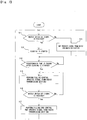
- Step S1 the nozzle signal block 35 of the information processer 32C (refer to Fig. 6 ) judges whether an ON signal is received from the nozzle switch or not. In case that the ON signal is received therefrom (Step S1; Yes), the control advances to Step S2. On the other hand, in Step S1, in case that the nozzle signal block 35 judges that the ON signal is not received (Step S1; No), the control advances to Step 3.
- Step S2 the clocking block 36 counts the time elapsed after the ON signal is received. And, the control advances to Step S4. In Step S3, the determination block 37 does not receive the ON signal from the nozzle signal block 35, and the control block 38C does not operate. After Step S3 is finished, the control returns to Step S1.
- Step S4 the control judges whether the predetermined time passes after the clocking starts in Step S2 or not. In case that the predetermined time passes after the clocking starts (Step S4; Yes), the control advances to Step S5. On the other hand, in case that the predetermined time does not pass after the clocking starts (Step S4; No), the control returns to Step S4.
- Step S5 filling control is carried out.
- the CPU board 40 processes the various signals, and transmits a predetermined control signal to devices of the filling apparatus 100.
- Step S5 the control block 38C of the information processer 32C operates and various signals are transmitted to the CPU board 40.
- the determination block 37 judges whether an OFF signal is received from the nozzle switch or not. In case that the OFF signal is received therefrom (Step S6; Yes), the control advances to Step S7. On the other hand, in case that the OFF signal is not received from the nozzle switch (Step S6; No), the control returns to Step S5.
- Step S7 a filling completion control is performed based on a predetermined protocol.
- the control block 38C of the information processer 32C does not operate, and the CPU board 40 doses not process the various signals transmitted from the radio transmission section 10.
- the CPU board 40 does not process the noise generated at unfilling state, so that load thereof can be decreased.
- Step S4 in Fig. 7 can be omitted, and a filling control base on Step 1 only can be performed.
- Other constructions and action effects thereof in the third embodiment are the same as those in the first and second embodiments.
- An information processer 32D configuring the radio receiving section 30D has a filling start/end signal block 39 and a control block 38D.
- arrows connecting the blocks indicate signal communicating lines.
- the filling start/end signal block 39 receives a filling start signal transmitted when the filling start button is pressed and a filling end signal when the filling end button is pressed via a radio signal converting block 31D.
- the filling start/end signal block 39 has functions of transmitting an operation signal to a control block 38D when the filling start signal is received, and transmitting a non-operation signal to the control block 38D when the filling end signal is received.
- the control block 38D receives the operation/non-operation signals from the filling start/end signal block 39, and receives the various signals transmitted form the radio transmission sections 10 via a radio signal converting block 31D.
- the control block 38D operates when the operation signal is received from the filling start/end signal block 39.
- the various signals transmitted from the radio transmission sections 10 are transmitted via a signal transmission block 33D to the CPU board 40.
- the CPU board 40 processes the various signals, and transmits a predetermined control signal to devices of the filling apparatus 100.
- the control block 38D does not operate until the operation signal is received from the filling start/end signal block 39 or until the hydrogen filling is started.
- the control block 38D stops when the non-operation signal is received from the filling start/end signal block 39.
- the various signals transmitted from the radio transmission section 10 are not transmitted to the CPU board 40, and the CPU board 40 judges that filling is not performed, and does not process the various signals. Even when the radio receiving section 30D receives a signal from the radio transmission sections 10, the CPU board 40 does not process the signal, so that load of the CPU board 40 is decreased.
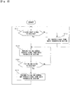
- Step S11 the filling start/end signal block 39 judges whether the filling start signal is received or not. In case that the filling start signal is received (Step S11; Yes), the control advances to Step S12. On the other hand, in case that the filling start signal is not received (Step S11; No), the control advances to Step 13.
- Step S12 the filling start signal is received, so that the control block 38D of the information processer 32D operates, and the various signals are transmitted to the CPU board 40. Therefore, a filling control is performed in Step S12.
- the CPU board 40 processes the various signals, and transmits a predetermined signal to devices of the filling apparatus 100.
- Step S14 the control advances to Step S14.
- Step S13 the filling start signal is not received, so that the control block 38D does not operate, and the CPU board 40 does not process the various signals transmitted from the radio transmission sections 10.
- Step S13 the control returns to Step S11.
- Step S14 the filling start/end signal block 39 judges whether the filling end signal is received or not. As described above, for example, when the filling is finished, pressing the filling start button again causes the filling end signal to be transmitted via the radio transmission sections 10 to the radio receiving section 30D. In case that the filling end signal is received (Step S14; Yes), the control advance to Step S15. On the other hand, the filling end signal is not received (Step S14; No), the control returns to Step 12, and the filling control is continued.
- Step S15 the filling end signal is received to perform a filling end control.
- the filling end control is performed based on a predetermined protocol.
- the control block 38D does not operate, and the CPU board 40 does not process the various signals transmitted from the radio transmission sections 10. The control returns to Step S11.
- the control block 38D judges that the filling is not performed and does not operate, and the CPU board 40 does not process the various signals transmitted from the radio transmission sections 10. Therefore, when noise generates at unfilling state, the noise is not processed in the CPU board 40, and load of the controller 20 is decreased.
- other constructions and action effects thereof in the fourth embodiment are the same as those in the embodiments shown in Figs. 1 to 7 .
- the present invention can be applied to a filling apparatus for filling gasoline or other fuels.
Landscapes
- Engineering & Computer Science (AREA)
- Mechanical Engineering (AREA)
- Power Engineering (AREA)
- Transportation (AREA)
- General Engineering & Computer Science (AREA)
- Computer Networks & Wireless Communication (AREA)
- Signal Processing (AREA)
- Thermal Sciences (AREA)
- Physics & Mathematics (AREA)
- Filling Or Discharging Of Gas Storage Vessels (AREA)
- Charge And Discharge Circuits For Batteries Or The Like (AREA)
- Selective Calling Equipment (AREA)
- Electric Propulsion And Braking For Vehicles (AREA)
- Toys (AREA)
- Details Of Aerials (AREA)
Abstract
Description
- The present invention relates to a filling apparatus for filling fuel such as hydrogen gas to a vehicle.
- In a conventional
hydrogen filling apparatus 200 shown inFig. 10 , aphotodetector 202 equipped onto a fillingnozzle 201 receives an optical signal including information such as tank pressure, tank temperature and the like from a communication device of a fuel cell vehicle (Society of Automotive Engineers: SAE-J2799); converts the optical signal into an electric serial communication signal; and transmits the converted signal via acable 204 to areceiver 203 mounted on a non-dangerous area. Thereceiver 203 transports the received signal to acontroller 205, and thecontroller 205 processes the signal to control devices of thehydrogen filling apparatus 200. - The
cable 204 is mounted not only to transmit signal but also to supply driving power, and is wired from a fillingnozzle 201 along a fillinghose 206 via an inside of thehydrogen filling apparatus 200 to thereceiver 203. Here, a filling work pulls and twists thecable 204, so that aconnecter part 204A and the like adjacent to the fillingnozzle 201 often breaks. When thecable 204 is disconnected, it becomes impossible to fill gas fuel such as hydrogen. In addition, since thecable 204 is long, thecable 204 is easily affected by electric noise from thehydrogen filling apparatus 200, there is a possibility that thecable 204 cannot concisely transmit signals due to the noise. - As another conventional technique, for example, a hydrogen filling apparatus allowing easy assembly is proposed (refer to Japanese
- Patent Publication
2015-137671 - The content of Japanese Patent Publication
2015-137671 - The present invention has been made in consideration of the above problems in the prior art, and the object thereof is to provide a filling apparatus capable of eliminating a disadvantage of the cable connecting the photodetector to the receiver.
- A filling
apparatus 100 of the present invention is characterized by including a radio transmission section (photodetector) 10 with a function of transmitting vehicle information via radio transmission on a fillingnozzle 50. - In the
filling apparatus 100 described above, it is preferable that theradio transmission section 10 is detachable from an end portion of the fillingnozzle 50. And, it is preferable that theradio transmission section 10 has an explosion-proof structure. - In the
filling apparatus 100 described above, theradio transmission section 10 preferably incorporates a buttery 15. Further, it is preferable that theradio transmission section 10 incorporates aninformation processor 13 and theinformation processor 13 has functions of checking the information of the vehicle with the fillingnozzle 50 and transmitting residual capacity of the buttery to thefilling apparatus 100. - In the
filling apparatus 100 described above, theinformation processor 13 preferably has a function of not transmitting noise generated from theradio transmission section 10. Or, it is preferable that a switch (automatic switch) 51 for operating/stopping theradio transmission section 10 is mounted on the fillingnozzle 50, and theswitch 51 has a function of transmitting a signal for operating theradio transmission section 10 when the fillingnozzle 50 is attached to the vehicle. - The filling
apparatus 100 described above preferably has acontroller 20, which has a function of processing a signal transmitted from theradio transmission section 10 only when thecontroller 20 receives a signal from a nozzle switch that acts when the fillingnozzle 50 is taken off a nozzle hook, and a predetermined time passes after the signal is received. Or, it is preferable that to thefilling apparatus 100 is mounted thecontroller 20; a filling start button is mounted on the fillingnozzle 50; and thecontroller 20 has a function of processing a signal transmitted from theradio transmission section 10 only when thecontroller 20 receives a signal indicating that the filling start button is pressed. - With the present invention, the
radio transmission section 10 having a function of transmitting vehicle information via radio transmission is mounted on the fillingnozzle 50, so that a communication cable is not needed, and a disadvantage due to disconnection of the cable does not generate. In addition, since the vehicle information is transmitted via a short-distance radio communication, it is not harmfully affected by electric noise. Further, no cable causes repair work to easily be performed when the fillingapparatus 100 is damaged or broken. - In the present invention, when the
radio transmission section 10 is detachable from an end portion of the fillingnozzle 50, it can be detached from the fillingnozzle 50 to be repaired easily and surely at breakage and the like. In addition, when theradio transmission section 10 has the explosion-proof structure, safety of the fillingapparatus 100 is improved. In the present invention, when theradio transmission section 10 incorporates the buttery 15, it becomes possible to operate without a cable for power supply. - Here, in case that the
radio transmission section 10 is always operated by thebuttery 15, there is a possibility that a noise such as a bias signal generated by sunshine is transmitted as a signal from theradio transmission section 10 to thecontroller 20 of thefilling apparatus 100. But, in the present invention, when theradio transmission section 10 incorporates theinformation processor 13, and theinformation processor 13 has a function of not transmitting the noise generated from theradio transmission section 10, it is prevented that the noise is transmitted to thecontroller 20 of thefilling apparatus 100, so that thecontroller 20 is not required to process the noise, and load of thecontroller 20 can be reduced. - Or, when the
switch 51 for operating/stopping theradio transmission section 10 is mounted on thefilling nozzle 50, and theswitch 51 has a function of transmitting a signal for operating theradio transmission section 10 when thefilling nozzle 50 is attached to the vehicle, even if sunlight irradiates theradio transmission section 10, theradio transmission section 10 does not operate without filling any fuel, so that it is prevented that the noise is transmitted to thecontroller 20, and load of thecontroller 20 can be reduced. - Further, when the
filling apparatus 100 according to the present invention has thecontroller 20, and thecontroller 20 has a function of processing a signal transmitted from theradio transmission section 10 only when thecontroller 20 receives a signal from a nozzle switch that acts when thefilling nozzle 50 is taken off a nozzle hook, and a predetermined time passes after the signal is received, thecontroller 20 of thefilling apparatus 100 judges that filling is not performed, that is, any kind of fuel is not filled, and thefilling apparatus 100 does not process the signal transmitted from theradio transmission section 10 until receiving the signal from the nozzle switch and the predetermined time passes. Therefore, thecontroller 20 does not process the noise generated when the filling is not performed and so on, and load of thecontroller 20 can be reduced. - Or, when the
filling apparatus 100 according to the present invention has thecontroller 20; the filling start button is mounted on thefilling nozzle 50; and thecontroller 20 has a function of processing the signal transmitted from theradio transmission section 10 only when thecontroller 20 receives the signal indicating that the filling start button is pressed, thecontroller 20 of thefilling apparatus 100 does not process signal transmitted from theradio transmission section 10 until the filling start button is pressed. Therefore, thecontroller 20 does not process a noise generated when the filling is not performed filling start button is pressed, and load of thecontroller 20 can be reduced. -
-
Figure 1 is a schematic view showing a filling apparatus according to the first embodiment of the present invention; -
Figure 2 is an explanatory view showing a condition that the filling nozzle is attached to/detached from a radio transmission section; -
Figure 3 is a block diagram of the radio transmission section and the controller of the filling apparatus; -
Figure 4 is a block diagram showing an information processer of the radio transmission section; -
Figure 5 is a schematic view showing a filling nozzle and a radio transmission section of a filling apparatus according to the second embodiment of the present invention; -
Figure 6 is a block diagram showing a filling apparatus according to the third embodiment of the present invention; -
Figure 7 is a flowchart showing a control in the third embodiment; -
Figure 8 is a block diagram showing a filling apparatus according to the fourth embodiment of the present invention; -
Figure 9 is a flowchart showing a control in the fourth embodiment; and -
Figure 10 is a schematic view showing a conventional filling apparatus. - Hereinafter, a filling apparatus for filling hydrogen will be explained as embodiments of the present invention with reference to attached drawings. At first, the filling apparatus according to the first embodiment of the present invention will be explained with reference to
Figs. 1 to 4 . InFig. 1 , thefilling apparatus 100 has aradio transmission section 10 such as a photodetector, and acontroller 20. As shown inFig 2 , theradio transmission section 10 is detachably attached to anend portion 50A of afilling nozzle 50 mounted to an end portion of a filling hose 60 (refer toFig. 1 ), and has a function of receiving information of a vehicle to which the fillingnozzle 50 is inserted such as tank pressure, tank temperature, tank capacity and the like to transmit the vehicle information via a short-distance radio communication to thecontroller 20. Theradio transmission section 10 has a sealing structure and an explosion-proof structure, and thecontroller 20 has an explosion-proof structure also. In addition, infrared ray communication is used as a radio communication system. - The
controller 20 is mounted in thefilling apparatus 100, and has aradio receiving section 30 such as a converter, and aCPU board 40. The vehicle information transmitted from theradio transmission section 10 is converted by theradio receiving section 30, and the converted information is transmitted to theCPU board 40 via serial communication or the like. When hydrogen is filled, theCPU board 40 processes the information transmitted from theradio transmission section 10 to control devices not shown of thefilling apparatus 100. - In
Fig. 3 , theradio transmission section 10 has an infraredray receiving block 11, asignal converting block 12, aninformation processor 13 such as a microcomputer, a radiosignal converting block 14, and abattery 15. When the filling nozzle 50 (refer toFigs. 1 and 2 ) is attached to a hydrogen filling port of a vehicle not shown, the vehicle information described above is transmitted via a vehicle information communicating system not shown mounted in the vehicle, and the infraredray receiving block 11 receives the vehicle information. The received information is transmitted via thesignal converting block 12 to theinformation processor 13. The vehicle information is processed by theinformation processor 13, and is transmitted via the radiosignal converting block 14 to thecontroller 20 through radio communication. Theradio transmission section 10 is operated by thebattery 15. - In
Fig. 3 , thecontroller 20 is mounted in thefilling apparatus 100, and theradio receiving section 30 of thecontroller 20 has a radiosignal converting block 31, aninformation processer 32, asignal transmitting block 33 and apower source part 34. The vehicle information transmitted from theradio transmission section 10 is received in the radiosignal converting block 31 of theradio receiving section 30, and is processed in theinformation processer 32, and is transmitted via thesignal transmitting block 33 to theCPU board 40 in serial communication for instance. To thepower source part 34 is supplied DC power from theCPU board 40. - As shown in
Figs 1 to 3 , this embodiment does not use theconventional cable 204 shown inFig. 10 , but adopts radio communication, which provides no problem caused by cables. - In case that the
radio transmission section 10 is always driven by the buttery 15, there is a possibility that sunlight shines on theradio transmission section 10 to generate a noise such as bias signal, and the noise is transmitted to thecontroller 20 of thehydrogen filling apparatus 100. In this connection, the first embodiment removes the noise by theinformation processer 13 mounted on theradio transmission section 10. - In
Fig 4 , theinformation processer 13 of theradio transmission section 10 has a vehicleinformation checking block 16 and a buttery residual capacitysignal generating block 19, and the vehicleinformation checking block 16 has ajudgement block 17 and anoise removing block 18. In addition, arrows connecting the blocks indicate signal communicating lines. Thejudgement block 17 of the vehicleinformation checking block 16 has a function of judging that the signal transmitted from thesignal converting block 12 is that relative to the vehicle information communicated via a communicating system in the vehicle, or noise due to sunshine with known technologies. Thenoise removing block 18 has a function of removing a signal judged as noise by thejudgement block 17 with known technologies. - When the vehicle information is transmitted from the
radio transmission section 10 to the controller 20 (refer toFigs. 1 and3 ), only signal that is not judged as the noise by thejudgement block 17 is transmitted via the radiosignal converting block 14 to thecontroller 20. Then, the signal judged as noise by thejudgement block 17 is removed by thenoise removing block 18 and is not transmitted to thecontroller 20. As a result, it is prevented that the noise due to sunshine is transmitted to thecontroller 20. InFig. 4 , the buttery residual capacitysignal generating block 19 has functions of determining residual capacity of thebattery 15 with known technologies and generating a signal indicating that the determined buttery residual capacity to transmit it via the radiosignal converting block 14 to thecontroller 20. - With the first embodiment described above, since the
radio transmission section 10 having a function of transmitting the vehicle information via the radio communication is mounted on the fillingnozzle 50, a communication cable is not needed. Then, disconnection of the cable can be avoided, and repair work of the fillingapparatus 100 becomes easy when it is damaged or broken. In addition, since the vehicle information is transmitted via radio communication, there is no possibility that a noise affects the vehicle information. - In addition, the
radio transmission section 10 is detachably attached to an end portion of the fillingnozzle 50, so that when being damaged theradio transmission section 10 can be detached from the fillingnozzle 50 to be repaired easily and certainly. Further, theradio transmission section 10 has an explosion-proof structure, so that safety of the fillingapparatus 100 can be maintained. In addition, theradio transmission section 10 incorporates the buttery 15, so that operation of the fillingapparatus 100 can be secured without cables. - Further, since the
radio transmission section 10 has theinformation processer 13, and a noise generated from theradio transmission section 10 is removed by the vehicleinformation checking block 16 including thejudgement block 17 and thenoise removing block 18, it is prevented that the noise is transported to thecontroller 20 of the fillingapparatus 100. Therefore, thecontroller 20 is not required to process the noise, and load on thecontroller 20 can be decreased. In addition, residual capacity of the buttery 15 for driving theradio transmission section 10 is managed by thecontroller 20, so that necessary measures can be taken immediately when the residual capacity decreases. - Next, a filling apparatus according to the second embodiment of the present invention will be explained with reference to
Fig. 5 . The present embodiment has a mode for processing the noise in theradio transmission section 10 that is different from that in the first embodiment (refer toFig. 4 ). InFig. 5 , theradio transmission section 10 is detachably attached to an end portion of the fillingnozzle 50, and has a radio transmissionsection driving block 21. On the fillingnozzle 50 is mounted anautomatic switch 51, and theautomatic switch 51 and the radio transmissionsection driving block 21 are connected with each other via a signal communication line SL. - The
automatic switch 51 has a function of transmitting an operation signal via the signal communication line SL to the radio transmissionsection driving block 21 when the fillingnozzle 50 is attached to the filling port of the vehicle, and has a function of transmitting a stop signal via the signal communication line SL to the radio transmissionsection driving block 21 when the fillingnozzle 50 is detached therefrom. The radio transmissionsection driving block 21 of theradio transmission section 10 has a function of operating theradio transmission section 10 when the operation signal is received from theautomatic switch 51, and has a function of stopping operation of theradio transmission section 10 when the operation stop signal is received from theautomatic switch 51. In the second embodiment shown inFig. 5 , unless the fillingnozzle 50 is attached to the filling port of the vehicle and theautomatic switch 51 turns ON, the radio transmissionsection driving block 21 does not operate theradio transmission section 10. Therefore, if a noise generates because sunlight irradiates theradio transmission section 10, theradio transmission section 10 does not operate, so that the noise is not transmitted to thecontroller 20 of the fillingapparatus 100. - With the second embodiment, the
radio transmission section 10 does not operate at unfilling state, so that generated noise is not transmitted to thecontroller 20, and load thereof can be decreased. Other constructions and action effects of the second embodiment are the same as those of the first embodiment described above. - Next, a filling apparatus according to the third embodiment of the present invention will be explained with reference to
Figs. 6 and7 . The filling apparatus according to the present embodiment has aradio transmission section 30C and a mode for processing noise that are different from those in the first and second embodiments. InFig. 6 , aninformation processer 32C constituting theradio receiving section 30C has anozzle signal block 35, aclocking block 36, adetermination block 37 and acontrol block 38C. In addition, arrows connecting the blocks indicate signal communicating lines. - Although not clearly shown in
Fig. 6 , when the filling nozzle is detached from a nozzle hook, an ON signal generates from a nozzle switch, and when the filling nozzle is hooked on the nozzle hook, an OFF signal generates from the nozzle switch. Thenozzle signal block 35 inFig. 6 has functions of receiving the nozzle switch ON/OFF signals via a radiosignal converting block 31C and transmitting the signals to thedetermination block 37. In addition, thenozzle signal block 35 has a function of transmitting a clocking start signal to theclocking block 36 when the nozzle switch ON signal is received from the nozzle switch. - When receiving the clocking start signal from the
nozzle signal block 35, theclocking block 36 counts time elapsed after the reception of the clocking start signal. Then, theclocking block 36 has a function of transmitting a predetermined time passage signal indicating that a predetermined time passes to thedetermination block 37. Here, the predetermined time is a time until the filling actually starts after the filling nozzle is detached from the nozzle hook, and the time is properly determined in accordance with kind of fuel and the like. Thedetermination block 37 has functions of judging that the filling is being actually performed when the nozzle switch ON signal from thenozzle signal block 35 and the predetermined time passage signal from theclocking block 36 are received, and transmitting an operation signal to thecontrol block 38C. When receiving the operation signal, thecontrol block 38C receives various signals such as signals indicating the vehicle information transmitted from theradio transmission section 10 via the radiosignal converting block 31C. - When receiving the operation signal from the
determination block 37, thecontrol block 38C operates, and the various signals transmitted from theradio transmission section 10 are processed in the control block 38C to be transmitted via thesignal transmitting block 33C to theCPU board 40. TheCPU board 40 processes the various signals to transmit predetermined control signals to devices of the fillingapparatus 100. On the other hand, thecontrol block 38C does not operate until the operation signal is received from thedetermination block 37. In other words, thecontrol block 38C does not operate until the predetermined time passes after the nozzle switch turns ON. In case that the nozzle switch OFF signal is transmitted from thenozzle signal block 35 to thedetermination block 37, thedetermination block 37 judges that the filling is not performed to stop transmitting the operation signal to thecontrol block 38C. As a result, thecontrol block 38C does not operate. - Until the
control block 38C operates, the various signals transmitted from theradio transmission section 10 are not transmitted to theCPU board 40 to be processed thereby. Until the predetermined time passes after the nozzle switch turns ON, the control block 38 does not operate, and theCPU board 40 does not process the signals from theradio transmission section 10. Therefore, if noise generates, the noise is not transmitted to theCPU board 40. And, load of theCPU board 40 is decreased. Meanwhile, in the third embodiment, theclocking block 36 may transmit time elapsed after the clocking starts only to thedetermination block 37, and thedetermination block 37 may judge whether the predetermined time passes or not. - Control in the third embodiment will be explained with reference to
Fig. 7 mainly. InFig. 7 , in Step S1, thenozzle signal block 35 of theinformation processer 32C (refer toFig. 6 ) judges whether an ON signal is received from the nozzle switch or not. In case that the ON signal is received therefrom (Step S1; Yes), the control advances to Step S2. On the other hand, in Step S1, in case that thenozzle signal block 35 judges that the ON signal is not received (Step S1; No), the control advances toStep 3. - In Step S2, the
clocking block 36 counts the time elapsed after the ON signal is received. And, the control advances to Step S4. In Step S3, thedetermination block 37 does not receive the ON signal from thenozzle signal block 35, and thecontrol block 38C does not operate. After Step S3 is finished, the control returns to Step S1. - In Step S4, the control judges whether the predetermined time passes after the clocking starts in Step S2 or not. In case that the predetermined time passes after the clocking starts (Step S4; Yes), the control advances to Step S5. On the other hand, in case that the predetermined time does not pass after the clocking starts (Step S4; No), the control returns to Step S4.
- In Step S5, filling control is carried out. In the control, the
CPU board 40 processes the various signals, and transmits a predetermined control signal to devices of the fillingapparatus 100. In Step S5, thecontrol block 38C of theinformation processer 32C operates and various signals are transmitted to theCPU board 40. In Step S6, thedetermination block 37 judges whether an OFF signal is received from the nozzle switch or not. In case that the OFF signal is received therefrom (Step S6; Yes), the control advances to Step S7. On the other hand, in case that the OFF signal is not received from the nozzle switch (Step S6; No), the control returns to Step S5. - In Step S7, a filling completion control is performed based on a predetermined protocol. With this, the
control block 38C of theinformation processer 32C does not operate, and theCPU board 40 doses not process the various signals transmitted from theradio transmission section 10. - With the third embodiment described above, the
CPU board 40 does not process the noise generated at unfilling state, so that load thereof can be decreased. In addition, in the present embodiment, Step S4 inFig. 7 can be omitted, and a filling control base onStep 1 only can be performed. Other constructions and action effects thereof in the third embodiment are the same as those in the first and second embodiments. - Next, a filling apparatus according to the fourth embodiment of the present invention will be explained with reference to
Figs. 8 and9 . In comparison to the first to third embodiments, constructions of a radio receiving section and a filling nozzle and mode for processing noise of this embodiment are different from those of the first to third embodiments. Aninformation processer 32D configuring theradio receiving section 30D has a filling start/end signal block 39 and acontrol block 38D. In addition, arrows connecting the blocks indicate signal communicating lines. - In the fourth embodiment, on the filling nozzle are mounted a filling start button and a filling end button. The filling start/
end signal block 39 receives a filling start signal transmitted when the filling start button is pressed and a filling end signal when the filling end button is pressed via a radio signal converting block 31D. The filling start/end signal block 39 has functions of transmitting an operation signal to acontrol block 38D when the filling start signal is received, and transmitting a non-operation signal to thecontrol block 38D when the filling end signal is received. Thecontrol block 38D receives the operation/non-operation signals from the filling start/end signal block 39, and receives the various signals transmitted form theradio transmission sections 10 via a radio signal converting block 31D. - The
control block 38D operates when the operation signal is received from the filling start/end signal block 39. When thecontrol block 38D operates, the various signals transmitted from theradio transmission sections 10 are transmitted via a signal transmission block 33D to theCPU board 40. TheCPU board 40 processes the various signals, and transmits a predetermined control signal to devices of the fillingapparatus 100. On the other hand, thecontrol block 38D does not operate until the operation signal is received from the filling start/end signal block 39 or until the hydrogen filling is started. In addition, thecontrol block 38D stops when the non-operation signal is received from the filling start/end signal block 39. In case that thecontrol block 38D does not operate, the various signals transmitted from theradio transmission section 10 are not transmitted to theCPU board 40, and theCPU board 40 judges that filling is not performed, and does not process the various signals. Even when theradio receiving section 30D receives a signal from theradio transmission sections 10, theCPU board 40 does not process the signal, so that load of theCPU board 40 is decreased. - Control in the fourth embodiment will be explained with reference to
Fig. 9 mainly. InFig. 9 , in Step S11, the filling start/end signal block 39 judges whether the filling start signal is received or not. In case that the filling start signal is received (Step S11; Yes), the control advances to Step S12. On the other hand, in case that the filling start signal is not received (Step S11; No), the control advances to Step 13. - In Step S12, the filling start signal is received, so that the
control block 38D of theinformation processer 32D operates, and the various signals are transmitted to theCPU board 40. Therefore, a filling control is performed in Step S12. At the filling control, theCPU board 40 processes the various signals, and transmits a predetermined signal to devices of the fillingapparatus 100. After the Step S12, the control advances to Step S14. In Step S13, the filling start signal is not received, so that thecontrol block 38D does not operate, and theCPU board 40 does not process the various signals transmitted from theradio transmission sections 10. After Step S13, the control returns to Step S11. - In Step S14, the filling start/
end signal block 39 judges whether the filling end signal is received or not. As described above, for example, when the filling is finished, pressing the filling start button again causes the filling end signal to be transmitted via theradio transmission sections 10 to theradio receiving section 30D. In case that the filling end signal is received (Step S14; Yes), the control advance to Step S15. On the other hand, the filling end signal is not received (Step S14; No), the control returns to Step 12, and the filling control is continued. - In Step S15, the filling end signal is received to perform a filling end control. The filling end control is performed based on a predetermined protocol. When the filling end control is performed, the
control block 38D does not operate, and theCPU board 40 does not process the various signals transmitted from theradio transmission sections 10. The control returns to Step S11. - With the fourth embodiment described above, until the filling start button is pressed, the
control block 38D judges that the filling is not performed and does not operate, and theCPU board 40 does not process the various signals transmitted from theradio transmission sections 10. Therefore, when noise generates at unfilling state, the noise is not processed in theCPU board 40, and load of thecontroller 20 is decreased. In addition, other constructions and action effects thereof in the fourth embodiment are the same as those in the embodiments shown inFigs. 1 to 7 . - Since the embodiments shown in the drawings are merely examples, and the embodiments do not limit the technical scope of the present invention. For example, the present invention can be applied to a filling apparatus for filling gasoline or other fuels.
-
- 10 radio transmission section
- 13 information processor
- 15 buttery
- 20 controller
- 40 CPU board
- 50 filling nozzle
- 51 automatic switch
- 100 filling apparatus
Claims (5)
- A filling apparatus comprising a radio transmission section with a function of transmitting vehicle information via radio transmission on a filling nozzle.
- The filling apparatus as claimed in claim 1, wherein the radio transmission section is detachably mounted to an end portion of the filling nozzle.
- The filling apparatus as claimed in claim 1 or 2, wherein the radio transmission section has an explosion-proof structure.
- The filling apparatus as claimed in one of claims 1 to 3, wherein the radio transmission section incorporates a buttery.
- The filling apparatus as claimed in claim 4, wherein the radio transmission section incorporates an information processor, and the information processor has functions of checking the vehicle information and transmitting residual capacity of the buttery.
Applications Claiming Priority (1)
| Application Number | Priority Date | Filing Date | Title |
|---|---|---|---|
| JP2017121136A JP6738561B2 (en) | 2017-06-21 | 2017-06-21 | Filling device |
Publications (3)
| Publication Number | Publication Date |
|---|---|
| EP3428020A2 true EP3428020A2 (en) | 2019-01-16 |
| EP3428020A3 EP3428020A3 (en) | 2019-05-15 |
| EP3428020B1 EP3428020B1 (en) | 2023-05-03 |
Family
ID=62715917
Family Applications (1)
| Application Number | Title | Priority Date | Filing Date |
|---|---|---|---|
| EP18178789.6A Active EP3428020B1 (en) | 2017-06-21 | 2018-06-20 | Filling apparatus |
Country Status (5)
| Country | Link |
|---|---|
| US (1) | US10396832B2 (en) |
| EP (1) | EP3428020B1 (en) |
| JP (1) | JP6738561B2 (en) |
| KR (1) | KR102122833B1 (en) |
| CN (1) | CN109099306B (en) |
Families Citing this family (7)
| Publication number | Priority date | Publication date | Assignee | Title |
|---|---|---|---|---|
| RU2709199C1 (en) * | 2016-05-24 | 2019-12-17 | Тацуно Корпорейшн | Device for gas filling |
| JP6737350B2 (en) * | 2019-01-16 | 2020-08-05 | 株式会社タツノ | Hydrogen filling system and hydrogen filling method |
| WO2020172100A1 (en) | 2019-02-18 | 2020-08-27 | Nikola Corporation | Communication systems and methods for hydrogen fueling and electric charging |
| JP7043031B2 (en) * | 2020-03-03 | 2022-03-29 | 株式会社タツノ | Filling device |
| KR20230051193A (en) | 2020-07-13 | 2023-04-17 | 아이비스 인크. | Hydrogen fuel supply system and method |
| DE102021209795A1 (en) * | 2021-09-06 | 2023-03-09 | Hyundai Motor Company | Alternative fuel vehicle refueling adapter and refueling method |
| US12292162B2 (en) * | 2022-03-22 | 2025-05-06 | Toyota Motor Engineering & Manufacturing North America, Inc. | Hydrogen refueling IR interference shield |
Citations (1)
| Publication number | Priority date | Publication date | Assignee | Title |
|---|---|---|---|---|
| JP2015137671A (en) | 2014-01-21 | 2015-07-30 | 株式会社タツノ | Gas filling device |
Family Cites Families (31)
| Publication number | Priority date | Publication date | Assignee | Title |
|---|---|---|---|---|
| JPH04128190A (en) * | 1990-09-06 | 1992-04-28 | Sharp Corp | Fuel feeding device for automobile |
| JPH06558B2 (en) * | 1991-02-26 | 1994-01-05 | トキコ株式会社 | Refueling device |
| JPH0655945A (en) * | 1992-08-04 | 1994-03-01 | Toyota Motor Corp | Bearing structure of differential gear |
| ATE267141T1 (en) * | 1995-03-10 | 2004-06-15 | Michael C Ryan | PUMP GUN FOR CONTROLLED DISPENSING OF LIQUIDS |
| JPH0993662A (en) * | 1995-09-25 | 1997-04-04 | Matsushita Electric Works Ltd | Remote control system |
| JP2001006086A (en) * | 1999-06-23 | 2001-01-12 | Nippon Signal Co Ltd:The | Vehicle managing card and car managing device using the same |
| US6374870B1 (en) * | 1999-08-11 | 2002-04-23 | Ide Til Produkt As | Fuel dispensing nozzle |
| JP2006220275A (en) * | 2005-02-14 | 2006-08-24 | Hitachi Ltd | Filling equipment |
| US7768409B2 (en) * | 2005-06-10 | 2010-08-03 | American Air Liquide, Inc. | Embedded RFID scanner for mobile product management |
| JP4760240B2 (en) * | 2005-09-06 | 2011-08-31 | オムロン株式会社 | Monitoring result processing apparatus, grouping method, working time measurement system, control program, and recording medium |
| WO2007049274A2 (en) * | 2005-10-24 | 2007-05-03 | Petratec International Ltd. | Devices and methods useful for authorizing purchases associated with a vehicle |
| ITMO20060202A1 (en) * | 2006-06-21 | 2007-12-22 | Galliano Bentivoglio | GUN TO DELIVER LIQUID FUEL |
| WO2008121325A1 (en) * | 2007-03-29 | 2008-10-09 | Berok Environmental Services Inc. | Liquid dispensing system |
| US20090048707A1 (en) * | 2007-08-15 | 2009-02-19 | Deline Jonathan E | Fuel dispenser |
| JP2009190746A (en) * | 2008-02-12 | 2009-08-27 | Fujitsu Ltd | Supply history information acquisition system |
| US20100001704A1 (en) * | 2008-07-07 | 2010-01-07 | Advanced Analogic Technologies, Inc. | Programmable Step-Down Switching Voltage Regulators with Adaptive Power MOSFETs |
| JP3151708U (en) * | 2009-04-21 | 2009-07-02 | 政彦 水嶋 | Oiling device and oiling system |
| JP5489752B2 (en) * | 2010-01-29 | 2014-05-14 | トヨタ自動車株式会社 | Gas filling system and vehicle |
| JP5115565B2 (en) * | 2010-02-15 | 2013-01-09 | トヨタ自動車株式会社 | vehicle |
| JP5556250B2 (en) * | 2010-03-09 | 2014-07-23 | トヨタ自動車株式会社 | High pressure gas supply system and fuel cell system |
| JP5757074B2 (en) * | 2010-08-20 | 2015-07-29 | トヨタ自動車株式会社 | Gas filling system and correction method |
| US8924037B2 (en) * | 2011-01-27 | 2014-12-30 | Continental Automotive Systems, Inc | Fuel-fill area data port |
| JP5698210B2 (en) * | 2012-12-19 | 2015-04-08 | 本田技研工業株式会社 | Fuel cell vehicle |
| JP2015196514A (en) * | 2014-03-31 | 2015-11-09 | 日立オートモティブシステムズメジャメント株式会社 | Fuel supply device |
| JP6375684B2 (en) * | 2014-05-07 | 2018-08-22 | 日産自動車株式会社 | Control device, fuel gas filling system, and fuel gas filling method |
| WO2015170670A1 (en) * | 2014-05-07 | 2015-11-12 | 日産自動車株式会社 | Fuel gas filling system and fuel gas filling method |
| US9846426B2 (en) * | 2014-07-28 | 2017-12-19 | Computational Systems, Inc. | Parallel digital signal processing of machine vibration data |
| JP2016039457A (en) * | 2014-08-06 | 2016-03-22 | 株式会社東海理化電機製作所 | Short-range radio system |
| EP2990490B1 (en) * | 2014-08-27 | 2020-09-23 | F. Hoffmann-La Roche AG | An analysis method and system for analyzing a nucleic acid amplification reaction |
| JP2018508330A (en) * | 2015-03-03 | 2018-03-29 | インボード・テクノロジー・インコーポレイテッドInboard Technology, Inc. | Handheld controller for motorized wheels |
| JP6055946B1 (en) * | 2016-03-29 | 2016-12-27 | 大陽日酸株式会社 | Simulated signal transmission device for fuel gas supply device |
-
2017
- 2017-06-21 JP JP2017121136A patent/JP6738561B2/en active Active
-
2018
- 2018-05-16 KR KR1020180055830A patent/KR102122833B1/en active Active
- 2018-06-15 US US16/010,252 patent/US10396832B2/en active Active
- 2018-06-20 EP EP18178789.6A patent/EP3428020B1/en active Active
- 2018-06-20 CN CN201810636030.XA patent/CN109099306B/en active Active
Patent Citations (1)
| Publication number | Priority date | Publication date | Assignee | Title |
|---|---|---|---|---|
| JP2015137671A (en) | 2014-01-21 | 2015-07-30 | 株式会社タツノ | Gas filling device |
Also Published As
| Publication number | Publication date |
|---|---|
| KR102122833B1 (en) | 2020-06-26 |
| US10396832B2 (en) | 2019-08-27 |
| CN109099306A (en) | 2018-12-28 |
| US20180375536A1 (en) | 2018-12-27 |
| EP3428020B1 (en) | 2023-05-03 |
| CN109099306B (en) | 2021-12-03 |
| KR20180138522A (en) | 2018-12-31 |
| EP3428020A3 (en) | 2019-05-15 |
| JP2019007501A (en) | 2019-01-17 |
| JP6738561B2 (en) | 2020-08-12 |
Similar Documents
| Publication | Publication Date | Title |
|---|---|---|
| EP3428020A2 (en) | Filling apparatus | |
| US11370651B2 (en) | Hydrogen filling system and hydrogen filling method | |
| US9403663B2 (en) | Managing remote control of an elevator system | |
| AU2009202248B2 (en) | Charging system and vehicle and charge controller for the charging system | |
| US20180088648A1 (en) | Power feeding system and negotiation controller | |
| JP5373408B2 (en) | Electric vehicle charging system, electric vehicle charging device, electric vehicle charging outlet device, and electric vehicle charging cable | |
| EP1731978B1 (en) | Robot controller having portable operating part | |
| JPH06343202A (en) | Electric vehicle charging device | |
| US6102491A (en) | Multi-function end of train device for electrically controlled pneumatic freight brake system | |
| KR20110096335A (en) | Vehicle smart key using mobile communication terminal and system including same | |
| US20170187056A1 (en) | Fuel cell vehicle | |
| KR101558387B1 (en) | System and method for sleep control of vehicle | |
| KR100627603B1 (en) | A device for automatically detecting separation of a trainformation | |
| KR20180077531A (en) | Charging control device for electric vehicle and communication mode control method thereof | |
| JP2002044752A (en) | Home control system | |
| KR20160045262A (en) | Apparatus and Method to Control Starting a Car on Emergency | |
| KR200402834Y1 (en) | Serial optical great distance transceiver(multi-ful converter) | |
| CN204731566U (en) | A kind of development machine automatic start-stop control system | |
| KR101133995B1 (en) | Device for measuring and controlling electric power | |
| JP7407658B2 (en) | Repeater used when charging electric vehicles | |
| KR100202427B1 (en) | How to set factory adjustment mode using remote control pin | |
| JP2009287835A (en) | Shutoff system | |
| KR20130011079A (en) | Method for judging limp home condition of button start vehicle, apparatus applied to the same | |
| JPH04243405A (en) | Power supply control signal converter | |
| MXPA99011468A (en) | Multi-function end of train device for electrically controlled pneumatic freight brake system |
Legal Events
| Date | Code | Title | Description |
|---|---|---|---|
| PUAI | Public reference made under article 153(3) epc to a published international application that has entered the european phase |
Free format text: ORIGINAL CODE: 0009012 |
|
| STAA | Information on the status of an ep patent application or granted ep patent |
Free format text: STATUS: THE APPLICATION HAS BEEN PUBLISHED |
|
| AK | Designated contracting states |
Kind code of ref document: A2 Designated state(s): AL AT BE BG CH CY CZ DE DK EE ES FI FR GB GR HR HU IE IS IT LI LT LU LV MC MK MT NL NO PL PT RO RS SE SI SK SM TR |
|
| AX | Request for extension of the european patent |
Extension state: BA ME |
|
| RIC1 | Information provided on ipc code assigned before grant |
Ipc: B60L 11/18 20060101ALI20181119BHEP Ipc: B60S 5/02 20060101AFI20181119BHEP |
|
| PUAL | Search report despatched |
Free format text: ORIGINAL CODE: 0009013 |
|
| AK | Designated contracting states |
Kind code of ref document: A3 Designated state(s): AL AT BE BG CH CY CZ DE DK EE ES FI FR GB GR HR HU IE IS IT LI LT LU LV MC MK MT NL NO PL PT RO RS SE SI SK SM TR |
|
| AX | Request for extension of the european patent |
Extension state: BA ME |
|
| RIC1 | Information provided on ipc code assigned before grant |
Ipc: B60S 5/02 20060101AFI20190409BHEP |
|
| STAA | Information on the status of an ep patent application or granted ep patent |
Free format text: STATUS: REQUEST FOR EXAMINATION WAS MADE |
|
| 17P | Request for examination filed |
Effective date: 20191115 |
|
| RBV | Designated contracting states (corrected) |
Designated state(s): AL AT BE BG CH CY CZ DE DK EE ES FI FR GB GR HR HU IE IS IT LI LT LU LV MC MK MT NL NO PL PT RO RS SE SI SK SM TR |
|
| STAA | Information on the status of an ep patent application or granted ep patent |
Free format text: STATUS: EXAMINATION IS IN PROGRESS |
|
| 17Q | First examination report despatched |
Effective date: 20210311 |
|
| GRAP | Despatch of communication of intention to grant a patent |
Free format text: ORIGINAL CODE: EPIDOSNIGR1 |
|
| STAA | Information on the status of an ep patent application or granted ep patent |
Free format text: STATUS: GRANT OF PATENT IS INTENDED |
|
| INTG | Intention to grant announced |
Effective date: 20230102 |
|
| GRAS | Grant fee paid |
Free format text: ORIGINAL CODE: EPIDOSNIGR3 |
|
| GRAA | (expected) grant |
Free format text: ORIGINAL CODE: 0009210 |
|
| STAA | Information on the status of an ep patent application or granted ep patent |
Free format text: STATUS: THE PATENT HAS BEEN GRANTED |
|
| AK | Designated contracting states |
Kind code of ref document: B1 Designated state(s): AL AT BE BG CH CY CZ DE DK EE ES FI FR GB GR HR HU IE IS IT LI LT LU LV MC MK MT NL NO PL PT RO RS SE SI SK SM TR |
|
| REG | Reference to a national code |
Ref country code: GB Ref legal event code: FG4D |
|
| REG | Reference to a national code |
Ref country code: DE Ref legal event code: R096 Ref document number: 602018049113 Country of ref document: DE |
|
| REG | Reference to a national code |
Ref country code: AT Ref legal event code: REF Ref document number: 1564331 Country of ref document: AT Kind code of ref document: T Effective date: 20230515 Ref country code: CH Ref legal event code: EP |
|
| REG | Reference to a national code |
Ref country code: IE Ref legal event code: FG4D |
|
| REG | Reference to a national code |
Ref country code: SE Ref legal event code: TRGR |
|
| REG | Reference to a national code |
Ref country code: NO Ref legal event code: T2 Effective date: 20230503 |
|
| REG | Reference to a national code |
Ref country code: LT Ref legal event code: MG9D |
|
| REG | Reference to a national code |
Ref country code: NL Ref legal event code: MP Effective date: 20230503 |
|
| REG | Reference to a national code |
Ref country code: AT Ref legal event code: MK05 Ref document number: 1564331 Country of ref document: AT Kind code of ref document: T Effective date: 20230503 |
|
| PG25 | Lapsed in a contracting state [announced via postgrant information from national office to epo] |
Ref country code: PT Free format text: LAPSE BECAUSE OF FAILURE TO SUBMIT A TRANSLATION OF THE DESCRIPTION OR TO PAY THE FEE WITHIN THE PRESCRIBED TIME-LIMIT Effective date: 20230904 Ref country code: NL Free format text: LAPSE BECAUSE OF FAILURE TO SUBMIT A TRANSLATION OF THE DESCRIPTION OR TO PAY THE FEE WITHIN THE PRESCRIBED TIME-LIMIT Effective date: 20230503 Ref country code: ES Free format text: LAPSE BECAUSE OF FAILURE TO SUBMIT A TRANSLATION OF THE DESCRIPTION OR TO PAY THE FEE WITHIN THE PRESCRIBED TIME-LIMIT Effective date: 20230503 Ref country code: AT Free format text: LAPSE BECAUSE OF FAILURE TO SUBMIT A TRANSLATION OF THE DESCRIPTION OR TO PAY THE FEE WITHIN THE PRESCRIBED TIME-LIMIT Effective date: 20230503 |
|
| PG25 | Lapsed in a contracting state [announced via postgrant information from national office to epo] |
Ref country code: RS Free format text: LAPSE BECAUSE OF FAILURE TO SUBMIT A TRANSLATION OF THE DESCRIPTION OR TO PAY THE FEE WITHIN THE PRESCRIBED TIME-LIMIT Effective date: 20230503 Ref country code: PL Free format text: LAPSE BECAUSE OF FAILURE TO SUBMIT A TRANSLATION OF THE DESCRIPTION OR TO PAY THE FEE WITHIN THE PRESCRIBED TIME-LIMIT Effective date: 20230503 Ref country code: LV Free format text: LAPSE BECAUSE OF FAILURE TO SUBMIT A TRANSLATION OF THE DESCRIPTION OR TO PAY THE FEE WITHIN THE PRESCRIBED TIME-LIMIT Effective date: 20230503 Ref country code: LT Free format text: LAPSE BECAUSE OF FAILURE TO SUBMIT A TRANSLATION OF THE DESCRIPTION OR TO PAY THE FEE WITHIN THE PRESCRIBED TIME-LIMIT Effective date: 20230503 Ref country code: IS Free format text: LAPSE BECAUSE OF FAILURE TO SUBMIT A TRANSLATION OF THE DESCRIPTION OR TO PAY THE FEE WITHIN THE PRESCRIBED TIME-LIMIT Effective date: 20230903 Ref country code: HR Free format text: LAPSE BECAUSE OF FAILURE TO SUBMIT A TRANSLATION OF THE DESCRIPTION OR TO PAY THE FEE WITHIN THE PRESCRIBED TIME-LIMIT Effective date: 20230503 Ref country code: GR Free format text: LAPSE BECAUSE OF FAILURE TO SUBMIT A TRANSLATION OF THE DESCRIPTION OR TO PAY THE FEE WITHIN THE PRESCRIBED TIME-LIMIT Effective date: 20230804 |
|
| PG25 | Lapsed in a contracting state [announced via postgrant information from national office to epo] |
Ref country code: FI Free format text: LAPSE BECAUSE OF FAILURE TO SUBMIT A TRANSLATION OF THE DESCRIPTION OR TO PAY THE FEE WITHIN THE PRESCRIBED TIME-LIMIT Effective date: 20230503 |
|
| PG25 | Lapsed in a contracting state [announced via postgrant information from national office to epo] |
Ref country code: SK Free format text: LAPSE BECAUSE OF FAILURE TO SUBMIT A TRANSLATION OF THE DESCRIPTION OR TO PAY THE FEE WITHIN THE PRESCRIBED TIME-LIMIT Effective date: 20230503 |
|
| PG25 | Lapsed in a contracting state [announced via postgrant information from national office to epo] |
Ref country code: SM Free format text: LAPSE BECAUSE OF FAILURE TO SUBMIT A TRANSLATION OF THE DESCRIPTION OR TO PAY THE FEE WITHIN THE PRESCRIBED TIME-LIMIT Effective date: 20230503 Ref country code: SK Free format text: LAPSE BECAUSE OF FAILURE TO SUBMIT A TRANSLATION OF THE DESCRIPTION OR TO PAY THE FEE WITHIN THE PRESCRIBED TIME-LIMIT Effective date: 20230503 Ref country code: RO Free format text: LAPSE BECAUSE OF FAILURE TO SUBMIT A TRANSLATION OF THE DESCRIPTION OR TO PAY THE FEE WITHIN THE PRESCRIBED TIME-LIMIT Effective date: 20230503 Ref country code: EE Free format text: LAPSE BECAUSE OF FAILURE TO SUBMIT A TRANSLATION OF THE DESCRIPTION OR TO PAY THE FEE WITHIN THE PRESCRIBED TIME-LIMIT Effective date: 20230503 Ref country code: DK Free format text: LAPSE BECAUSE OF FAILURE TO SUBMIT A TRANSLATION OF THE DESCRIPTION OR TO PAY THE FEE WITHIN THE PRESCRIBED TIME-LIMIT Effective date: 20230503 |
|
| REG | Reference to a national code |
Ref country code: DE Ref legal event code: R097 Ref document number: 602018049113 Country of ref document: DE |
|
| REG | Reference to a national code |
Ref country code: BE Ref legal event code: MM Effective date: 20230630 |
|
| PG25 | Lapsed in a contracting state [announced via postgrant information from national office to epo] |
Ref country code: MC Free format text: LAPSE BECAUSE OF FAILURE TO SUBMIT A TRANSLATION OF THE DESCRIPTION OR TO PAY THE FEE WITHIN THE PRESCRIBED TIME-LIMIT Effective date: 20230503 |
|
| PG25 | Lapsed in a contracting state [announced via postgrant information from national office to epo] |
Ref country code: MC Free format text: LAPSE BECAUSE OF FAILURE TO SUBMIT A TRANSLATION OF THE DESCRIPTION OR TO PAY THE FEE WITHIN THE PRESCRIBED TIME-LIMIT Effective date: 20230503 |
|
| PG25 | Lapsed in a contracting state [announced via postgrant information from national office to epo] |
Ref country code: LU Free format text: LAPSE BECAUSE OF NON-PAYMENT OF DUE FEES Effective date: 20230620 |
|
| PLBE | No opposition filed within time limit |
Free format text: ORIGINAL CODE: 0009261 |
|
| STAA | Information on the status of an ep patent application or granted ep patent |
Free format text: STATUS: NO OPPOSITION FILED WITHIN TIME LIMIT |
|
| REG | Reference to a national code |
Ref country code: IE Ref legal event code: MM4A |
|
| PG25 | Lapsed in a contracting state [announced via postgrant information from national office to epo] |
Ref country code: LU Free format text: LAPSE BECAUSE OF NON-PAYMENT OF DUE FEES Effective date: 20230620 |
|
| 26N | No opposition filed |
Effective date: 20240206 |
|
| PG25 | Lapsed in a contracting state [announced via postgrant information from national office to epo] |
Ref country code: IE Free format text: LAPSE BECAUSE OF NON-PAYMENT OF DUE FEES Effective date: 20230620 |
|
| PG25 | Lapsed in a contracting state [announced via postgrant information from national office to epo] |
Ref country code: IE Free format text: LAPSE BECAUSE OF NON-PAYMENT OF DUE FEES Effective date: 20230620 |
|
| PG25 | Lapsed in a contracting state [announced via postgrant information from national office to epo] |
Ref country code: SI Free format text: LAPSE BECAUSE OF FAILURE TO SUBMIT A TRANSLATION OF THE DESCRIPTION OR TO PAY THE FEE WITHIN THE PRESCRIBED TIME-LIMIT Effective date: 20230503 |
|
| PG25 | Lapsed in a contracting state [announced via postgrant information from national office to epo] |
Ref country code: SI Free format text: LAPSE BECAUSE OF FAILURE TO SUBMIT A TRANSLATION OF THE DESCRIPTION OR TO PAY THE FEE WITHIN THE PRESCRIBED TIME-LIMIT Effective date: 20230503 Ref country code: BE Free format text: LAPSE BECAUSE OF NON-PAYMENT OF DUE FEES Effective date: 20230630 |
|
| PG25 | Lapsed in a contracting state [announced via postgrant information from national office to epo] |
Ref country code: BG Free format text: LAPSE BECAUSE OF FAILURE TO SUBMIT A TRANSLATION OF THE DESCRIPTION OR TO PAY THE FEE WITHIN THE PRESCRIBED TIME-LIMIT Effective date: 20230503 |
|
| PG25 | Lapsed in a contracting state [announced via postgrant information from national office to epo] |
Ref country code: BG Free format text: LAPSE BECAUSE OF FAILURE TO SUBMIT A TRANSLATION OF THE DESCRIPTION OR TO PAY THE FEE WITHIN THE PRESCRIBED TIME-LIMIT Effective date: 20230503 |
|
| PGFP | Annual fee paid to national office [announced via postgrant information from national office to epo] |
Ref country code: GB Payment date: 20250618 Year of fee payment: 8 |
|
| PGFP | Annual fee paid to national office [announced via postgrant information from national office to epo] |
Ref country code: NO Payment date: 20250624 Year of fee payment: 8 |
|
| PGFP | Annual fee paid to national office [announced via postgrant information from national office to epo] |
Ref country code: FR Payment date: 20250625 Year of fee payment: 8 |
|
| PG25 | Lapsed in a contracting state [announced via postgrant information from national office to epo] |
Ref country code: CY Free format text: LAPSE BECAUSE OF FAILURE TO SUBMIT A TRANSLATION OF THE DESCRIPTION OR TO PAY THE FEE WITHIN THE PRESCRIBED TIME-LIMIT; INVALID AB INITIO Effective date: 20180620 |
|
| PGFP | Annual fee paid to national office [announced via postgrant information from national office to epo] |
Ref country code: CZ Payment date: 20250617 Year of fee payment: 8 |
|
| PGFP | Annual fee paid to national office [announced via postgrant information from national office to epo] |
Ref country code: SE Payment date: 20250618 Year of fee payment: 8 |
|
| PG25 | Lapsed in a contracting state [announced via postgrant information from national office to epo] |
Ref country code: HU Free format text: LAPSE BECAUSE OF FAILURE TO SUBMIT A TRANSLATION OF THE DESCRIPTION OR TO PAY THE FEE WITHIN THE PRESCRIBED TIME-LIMIT; INVALID AB INITIO Effective date: 20180620 |
|
| PGFP | Annual fee paid to national office [announced via postgrant information from national office to epo] |
Ref country code: DE Payment date: 20250630 Year of fee payment: 8 |
|
| PGFP | Annual fee paid to national office [announced via postgrant information from national office to epo] |
Ref country code: IT Payment date: 20250624 Year of fee payment: 8 |
|
| PGFP | Annual fee paid to national office [announced via postgrant information from national office to epo] |
Ref country code: CH Payment date: 20250701 Year of fee payment: 8 |
|
| PG25 | Lapsed in a contracting state [announced via postgrant information from national office to epo] |
Ref country code: TR Free format text: LAPSE BECAUSE OF FAILURE TO SUBMIT A TRANSLATION OF THE DESCRIPTION OR TO PAY THE FEE WITHIN THE PRESCRIBED TIME-LIMIT Effective date: 20230503 |