EP3427703B1 - Stent and delivery system - Google Patents
Stent and delivery system Download PDFInfo
- Publication number
- EP3427703B1 EP3427703B1 EP18184952.2A EP18184952A EP3427703B1 EP 3427703 B1 EP3427703 B1 EP 3427703B1 EP 18184952 A EP18184952 A EP 18184952A EP 3427703 B1 EP3427703 B1 EP 3427703B1
- Authority
- EP
- European Patent Office
- Prior art keywords
- lattice structure
- aneurysm
- stent
- lattice
- tubular body
- Prior art date
- Legal status (The legal status is an assumption and is not a legal conclusion. Google has not performed a legal analysis and makes no representation as to the accuracy of the status listed.)
- Active
Links
- 206010002329 Aneurysm Diseases 0.000 description 293
- 239000010410 layer Substances 0.000 description 262
- 210000004204 blood vessel Anatomy 0.000 description 102
- 238000009954 braiding Methods 0.000 description 79
- 230000002829 reductive effect Effects 0.000 description 38
- 210000004027 cell Anatomy 0.000 description 33
- 210000004369 blood Anatomy 0.000 description 32
- 239000008280 blood Substances 0.000 description 32
- 230000017531 blood circulation Effects 0.000 description 31
- 230000000694 effects Effects 0.000 description 30
- 230000002093 peripheral effect Effects 0.000 description 24
- 230000008859 change Effects 0.000 description 15
- 230000002792 vascular Effects 0.000 description 15
- 230000015572 biosynthetic process Effects 0.000 description 14
- 230000007850 degeneration Effects 0.000 description 13
- 230000036772 blood pressure Effects 0.000 description 12
- 230000006870 function Effects 0.000 description 12
- 208000037834 fusiform aneurysm Diseases 0.000 description 11
- 238000004904 shortening Methods 0.000 description 10
- 230000008901 benefit Effects 0.000 description 9
- 230000005540 biological transmission Effects 0.000 description 9
- 230000009467 reduction Effects 0.000 description 9
- 238000004519 manufacturing process Methods 0.000 description 8
- 238000010438 heat treatment Methods 0.000 description 7
- 238000004873 anchoring Methods 0.000 description 6
- 239000012781 shape memory material Substances 0.000 description 6
- 230000035488 systolic blood pressure Effects 0.000 description 6
- 230000007704 transition Effects 0.000 description 6
- 238000005452 bending Methods 0.000 description 5
- 238000012546 transfer Methods 0.000 description 5
- 230000006399 behavior Effects 0.000 description 4
- 230000003247 decreasing effect Effects 0.000 description 4
- 230000001976 improved effect Effects 0.000 description 4
- 238000000034 method Methods 0.000 description 4
- 238000000926 separation method Methods 0.000 description 4
- 208000007536 Thrombosis Diseases 0.000 description 3
- 208000027418 Wounds and injury Diseases 0.000 description 3
- 230000006978 adaptation Effects 0.000 description 3
- 230000000903 blocking effect Effects 0.000 description 3
- 230000006835 compression Effects 0.000 description 3
- 238000007906 compression Methods 0.000 description 3
- 238000010276 construction Methods 0.000 description 3
- 230000007423 decrease Effects 0.000 description 3
- 238000011161 development Methods 0.000 description 3
- 239000000463 material Substances 0.000 description 3
- 235000015097 nutrients Nutrition 0.000 description 3
- 230000035699 permeability Effects 0.000 description 3
- 230000002980 postoperative effect Effects 0.000 description 3
- 230000008569 process Effects 0.000 description 3
- 230000000541 pulsatile effect Effects 0.000 description 3
- 230000000284 resting effect Effects 0.000 description 3
- 230000001960 triggered effect Effects 0.000 description 3
- 208000032843 Hemorrhage Diseases 0.000 description 2
- 238000009825 accumulation Methods 0.000 description 2
- 230000002411 adverse Effects 0.000 description 2
- 238000013459 approach Methods 0.000 description 2
- 210000001367 artery Anatomy 0.000 description 2
- 208000034158 bleeding Diseases 0.000 description 2
- 230000000740 bleeding effect Effects 0.000 description 2
- 210000005242 cardiac chamber Anatomy 0.000 description 2
- 230000015271 coagulation Effects 0.000 description 2
- 238000005345 coagulation Methods 0.000 description 2
- 230000006378 damage Effects 0.000 description 2
- 238000013461 design Methods 0.000 description 2
- 238000006073 displacement reaction Methods 0.000 description 2
- 230000001771 impaired effect Effects 0.000 description 2
- 210000000663 muscle cell Anatomy 0.000 description 2
- HLXZNVUGXRDIFK-UHFFFAOYSA-N nickel titanium Chemical compound [Ti].[Ti].[Ti].[Ti].[Ti].[Ti].[Ti].[Ti].[Ti].[Ti].[Ti].[Ni].[Ni].[Ni].[Ni].[Ni].[Ni].[Ni].[Ni].[Ni].[Ni].[Ni].[Ni].[Ni].[Ni] HLXZNVUGXRDIFK-UHFFFAOYSA-N 0.000 description 2
- 229910001000 nickel titanium Inorganic materials 0.000 description 2
- 210000000056 organ Anatomy 0.000 description 2
- 230000036961 partial effect Effects 0.000 description 2
- 230000000737 periodic effect Effects 0.000 description 2
- 230000000717 retained effect Effects 0.000 description 2
- 230000002441 reversible effect Effects 0.000 description 2
- 239000011343 solid material Substances 0.000 description 2
- 206010005746 Blood pressure fluctuation Diseases 0.000 description 1
- 206010053567 Coagulopathies Diseases 0.000 description 1
- 208000012868 Overgrowth Diseases 0.000 description 1
- 230000001154 acute effect Effects 0.000 description 1
- 238000004026 adhesive bonding Methods 0.000 description 1
- 238000005054 agglomeration Methods 0.000 description 1
- 230000002776 aggregation Effects 0.000 description 1
- 210000003484 anatomy Anatomy 0.000 description 1
- 230000000747 cardiac effect Effects 0.000 description 1
- 210000000748 cardiovascular system Anatomy 0.000 description 1
- 230000035602 clotting Effects 0.000 description 1
- 230000003750 conditioning effect Effects 0.000 description 1
- 238000002788 crimping Methods 0.000 description 1
- 238000005520 cutting process Methods 0.000 description 1
- 230000000593 degrading effect Effects 0.000 description 1
- 230000010339 dilation Effects 0.000 description 1
- 230000009977 dual effect Effects 0.000 description 1
- 230000005489 elastic deformation Effects 0.000 description 1
- 238000004049 embossing Methods 0.000 description 1
- 238000005516 engineering process Methods 0.000 description 1
- 210000003743 erythrocyte Anatomy 0.000 description 1
- 208000014674 injury Diseases 0.000 description 1
- 230000003993 interaction Effects 0.000 description 1
- 230000003446 memory effect Effects 0.000 description 1
- 239000002184 metal Substances 0.000 description 1
- 210000003205 muscle Anatomy 0.000 description 1
- 230000034958 pharyngeal pumping Effects 0.000 description 1
- 230000035479 physiological effects, processes and functions Effects 0.000 description 1
- 230000001737 promoting effect Effects 0.000 description 1
- 230000010349 pulsation Effects 0.000 description 1
- 230000001105 regulatory effect Effects 0.000 description 1
- 230000003014 reinforcing effect Effects 0.000 description 1
- 230000003716 rejuvenation Effects 0.000 description 1
- 230000004044 response Effects 0.000 description 1
- 238000007493 shaping process Methods 0.000 description 1
- 239000002356 single layer Substances 0.000 description 1
- 238000005476 soldering Methods 0.000 description 1
- 230000006641 stabilisation Effects 0.000 description 1
- 238000011105 stabilization Methods 0.000 description 1
- 230000000087 stabilizing effect Effects 0.000 description 1
- 230000008093 supporting effect Effects 0.000 description 1
- 238000011144 upstream manufacturing Methods 0.000 description 1
- 230000003313 weakening effect Effects 0.000 description 1
- 238000003466 welding Methods 0.000 description 1
Images


Classifications
-
- A—HUMAN NECESSITIES
- A61—MEDICAL OR VETERINARY SCIENCE; HYGIENE
- A61F—FILTERS IMPLANTABLE INTO BLOOD VESSELS; PROSTHESES; DEVICES PROVIDING PATENCY TO, OR PREVENTING COLLAPSING OF, TUBULAR STRUCTURES OF THE BODY, e.g. STENTS; ORTHOPAEDIC, NURSING OR CONTRACEPTIVE DEVICES; FOMENTATION; TREATMENT OR PROTECTION OF EYES OR EARS; BANDAGES, DRESSINGS OR ABSORBENT PADS; FIRST-AID KITS
- A61F2/00—Filters implantable into blood vessels; Prostheses, i.e. artificial substitutes or replacements for parts of the body; Appliances for connecting them with the body; Devices providing patency to, or preventing collapsing of, tubular structures of the body, e.g. stents
- A61F2/82—Devices providing patency to, or preventing collapsing of, tubular structures of the body, e.g. stents
- A61F2/86—Stents in a form characterised by the wire-like elements; Stents in the form characterised by a net-like or mesh-like structure
- A61F2/90—Stents in a form characterised by the wire-like elements; Stents in the form characterised by a net-like or mesh-like structure characterised by a net-like or mesh-like structure
-
- A—HUMAN NECESSITIES
- A61—MEDICAL OR VETERINARY SCIENCE; HYGIENE
- A61B—DIAGNOSIS; SURGERY; IDENTIFICATION
- A61B17/00—Surgical instruments, devices or methods, e.g. tourniquets
- A61B17/12—Surgical instruments, devices or methods, e.g. tourniquets for ligaturing or otherwise compressing tubular parts of the body, e.g. blood vessels, umbilical cord
- A61B17/12022—Occluding by internal devices, e.g. balloons or releasable wires
- A61B17/12099—Occluding by internal devices, e.g. balloons or releasable wires characterised by the location of the occluder
- A61B17/12109—Occluding by internal devices, e.g. balloons or releasable wires characterised by the location of the occluder in a blood vessel
- A61B17/12113—Occluding by internal devices, e.g. balloons or releasable wires characterised by the location of the occluder in a blood vessel within an aneurysm
- A61B17/12118—Occluding by internal devices, e.g. balloons or releasable wires characterised by the location of the occluder in a blood vessel within an aneurysm for positioning in conjunction with a stent
-
- A—HUMAN NECESSITIES
- A61—MEDICAL OR VETERINARY SCIENCE; HYGIENE
- A61F—FILTERS IMPLANTABLE INTO BLOOD VESSELS; PROSTHESES; DEVICES PROVIDING PATENCY TO, OR PREVENTING COLLAPSING OF, TUBULAR STRUCTURES OF THE BODY, e.g. STENTS; ORTHOPAEDIC, NURSING OR CONTRACEPTIVE DEVICES; FOMENTATION; TREATMENT OR PROTECTION OF EYES OR EARS; BANDAGES, DRESSINGS OR ABSORBENT PADS; FIRST-AID KITS
- A61F2/00—Filters implantable into blood vessels; Prostheses, i.e. artificial substitutes or replacements for parts of the body; Appliances for connecting them with the body; Devices providing patency to, or preventing collapsing of, tubular structures of the body, e.g. stents
- A61F2/82—Devices providing patency to, or preventing collapsing of, tubular structures of the body, e.g. stents
- A61F2/852—Two or more distinct overlapping stents
-
- A—HUMAN NECESSITIES
- A61—MEDICAL OR VETERINARY SCIENCE; HYGIENE
- A61F—FILTERS IMPLANTABLE INTO BLOOD VESSELS; PROSTHESES; DEVICES PROVIDING PATENCY TO, OR PREVENTING COLLAPSING OF, TUBULAR STRUCTURES OF THE BODY, e.g. STENTS; ORTHOPAEDIC, NURSING OR CONTRACEPTIVE DEVICES; FOMENTATION; TREATMENT OR PROTECTION OF EYES OR EARS; BANDAGES, DRESSINGS OR ABSORBENT PADS; FIRST-AID KITS
- A61F2/00—Filters implantable into blood vessels; Prostheses, i.e. artificial substitutes or replacements for parts of the body; Appliances for connecting them with the body; Devices providing patency to, or preventing collapsing of, tubular structures of the body, e.g. stents
- A61F2/95—Instruments specially adapted for placement or removal of stents or stent-grafts
-
- A—HUMAN NECESSITIES
- A61—MEDICAL OR VETERINARY SCIENCE; HYGIENE
- A61F—FILTERS IMPLANTABLE INTO BLOOD VESSELS; PROSTHESES; DEVICES PROVIDING PATENCY TO, OR PREVENTING COLLAPSING OF, TUBULAR STRUCTURES OF THE BODY, e.g. STENTS; ORTHOPAEDIC, NURSING OR CONTRACEPTIVE DEVICES; FOMENTATION; TREATMENT OR PROTECTION OF EYES OR EARS; BANDAGES, DRESSINGS OR ABSORBENT PADS; FIRST-AID KITS
- A61F2/00—Filters implantable into blood vessels; Prostheses, i.e. artificial substitutes or replacements for parts of the body; Appliances for connecting them with the body; Devices providing patency to, or preventing collapsing of, tubular structures of the body, e.g. stents
- A61F2/02—Prostheses implantable into the body
- A61F2/04—Hollow or tubular parts of organs, e.g. bladders, tracheae, bronchi or bile ducts
- A61F2/06—Blood vessels
- A61F2/07—Stent-grafts
- A61F2002/077—Stent-grafts having means to fill the space between stent-graft and aneurysm wall, e.g. a sleeve
-
- A—HUMAN NECESSITIES
- A61—MEDICAL OR VETERINARY SCIENCE; HYGIENE
- A61F—FILTERS IMPLANTABLE INTO BLOOD VESSELS; PROSTHESES; DEVICES PROVIDING PATENCY TO, OR PREVENTING COLLAPSING OF, TUBULAR STRUCTURES OF THE BODY, e.g. STENTS; ORTHOPAEDIC, NURSING OR CONTRACEPTIVE DEVICES; FOMENTATION; TREATMENT OR PROTECTION OF EYES OR EARS; BANDAGES, DRESSINGS OR ABSORBENT PADS; FIRST-AID KITS
- A61F2/00—Filters implantable into blood vessels; Prostheses, i.e. artificial substitutes or replacements for parts of the body; Appliances for connecting them with the body; Devices providing patency to, or preventing collapsing of, tubular structures of the body, e.g. stents
- A61F2/82—Devices providing patency to, or preventing collapsing of, tubular structures of the body, e.g. stents
- A61F2002/823—Stents, different from stent-grafts, adapted to cover an aneurysm
-
- A—HUMAN NECESSITIES
- A61—MEDICAL OR VETERINARY SCIENCE; HYGIENE
- A61F—FILTERS IMPLANTABLE INTO BLOOD VESSELS; PROSTHESES; DEVICES PROVIDING PATENCY TO, OR PREVENTING COLLAPSING OF, TUBULAR STRUCTURES OF THE BODY, e.g. STENTS; ORTHOPAEDIC, NURSING OR CONTRACEPTIVE DEVICES; FOMENTATION; TREATMENT OR PROTECTION OF EYES OR EARS; BANDAGES, DRESSINGS OR ABSORBENT PADS; FIRST-AID KITS
- A61F2210/00—Particular material properties of prostheses classified in groups A61F2/00 - A61F2/26 or A61F2/82 or A61F9/00 or A61F11/00 or subgroups thereof
- A61F2210/0076—Particular material properties of prostheses classified in groups A61F2/00 - A61F2/26 or A61F2/82 or A61F9/00 or A61F11/00 or subgroups thereof multilayered, e.g. laminated structures
-
- A—HUMAN NECESSITIES
- A61—MEDICAL OR VETERINARY SCIENCE; HYGIENE
- A61F—FILTERS IMPLANTABLE INTO BLOOD VESSELS; PROSTHESES; DEVICES PROVIDING PATENCY TO, OR PREVENTING COLLAPSING OF, TUBULAR STRUCTURES OF THE BODY, e.g. STENTS; ORTHOPAEDIC, NURSING OR CONTRACEPTIVE DEVICES; FOMENTATION; TREATMENT OR PROTECTION OF EYES OR EARS; BANDAGES, DRESSINGS OR ABSORBENT PADS; FIRST-AID KITS
- A61F2230/00—Geometry of prostheses classified in groups A61F2/00 - A61F2/26 or A61F2/82 or A61F9/00 or A61F11/00 or subgroups thereof
- A61F2230/0002—Two-dimensional shapes, e.g. cross-sections
- A61F2230/0004—Rounded shapes, e.g. with rounded corners
- A61F2230/0008—Rounded shapes, e.g. with rounded corners elliptical or oval
-
- A—HUMAN NECESSITIES
- A61—MEDICAL OR VETERINARY SCIENCE; HYGIENE
- A61F—FILTERS IMPLANTABLE INTO BLOOD VESSELS; PROSTHESES; DEVICES PROVIDING PATENCY TO, OR PREVENTING COLLAPSING OF, TUBULAR STRUCTURES OF THE BODY, e.g. STENTS; ORTHOPAEDIC, NURSING OR CONTRACEPTIVE DEVICES; FOMENTATION; TREATMENT OR PROTECTION OF EYES OR EARS; BANDAGES, DRESSINGS OR ABSORBENT PADS; FIRST-AID KITS
- A61F2250/00—Special features of prostheses classified in groups A61F2/00 - A61F2/26 or A61F2/82 or A61F9/00 or A61F11/00 or subgroups thereof
- A61F2250/0014—Special features of prostheses classified in groups A61F2/00 - A61F2/26 or A61F2/82 or A61F9/00 or A61F11/00 or subgroups thereof having different values of a given property or geometrical feature, e.g. mechanical property or material property, at different locations within the same prosthesis
- A61F2250/0015—Special features of prostheses classified in groups A61F2/00 - A61F2/26 or A61F2/82 or A61F9/00 or A61F11/00 or subgroups thereof having different values of a given property or geometrical feature, e.g. mechanical property or material property, at different locations within the same prosthesis differing in density or specific weight
-
- A—HUMAN NECESSITIES
- A61—MEDICAL OR VETERINARY SCIENCE; HYGIENE
- A61F—FILTERS IMPLANTABLE INTO BLOOD VESSELS; PROSTHESES; DEVICES PROVIDING PATENCY TO, OR PREVENTING COLLAPSING OF, TUBULAR STRUCTURES OF THE BODY, e.g. STENTS; ORTHOPAEDIC, NURSING OR CONTRACEPTIVE DEVICES; FOMENTATION; TREATMENT OR PROTECTION OF EYES OR EARS; BANDAGES, DRESSINGS OR ABSORBENT PADS; FIRST-AID KITS
- A61F2250/00—Special features of prostheses classified in groups A61F2/00 - A61F2/26 or A61F2/82 or A61F9/00 or A61F11/00 or subgroups thereof
- A61F2250/0014—Special features of prostheses classified in groups A61F2/00 - A61F2/26 or A61F2/82 or A61F9/00 or A61F11/00 or subgroups thereof having different values of a given property or geometrical feature, e.g. mechanical property or material property, at different locations within the same prosthesis
- A61F2250/0036—Special features of prostheses classified in groups A61F2/00 - A61F2/26 or A61F2/82 or A61F9/00 or A61F11/00 or subgroups thereof having different values of a given property or geometrical feature, e.g. mechanical property or material property, at different locations within the same prosthesis differing in thickness
-
- A—HUMAN NECESSITIES
- A61—MEDICAL OR VETERINARY SCIENCE; HYGIENE
- A61F—FILTERS IMPLANTABLE INTO BLOOD VESSELS; PROSTHESES; DEVICES PROVIDING PATENCY TO, OR PREVENTING COLLAPSING OF, TUBULAR STRUCTURES OF THE BODY, e.g. STENTS; ORTHOPAEDIC, NURSING OR CONTRACEPTIVE DEVICES; FOMENTATION; TREATMENT OR PROTECTION OF EYES OR EARS; BANDAGES, DRESSINGS OR ABSORBENT PADS; FIRST-AID KITS
- A61F2250/00—Special features of prostheses classified in groups A61F2/00 - A61F2/26 or A61F2/82 or A61F9/00 or A61F11/00 or subgroups thereof
- A61F2250/0058—Additional features; Implant or prostheses properties not otherwise provided for
- A61F2250/006—Additional features; Implant or prostheses properties not otherwise provided for modular
- A61F2250/0063—Nested prosthetic parts
Definitions
- the invention relates to a stent according to the preamble of patent claim 1.
- the invention also relates to a system with such a stent.
- a stent of the type mentioned above is made, for example DE 601 28 588 T2 , EP 1 645 246 A1 or US 2007/0168019 A1 known.
- EP 1 645 246 A1 describes an aneurysm stent made of two tubular, coaxially arranged braids, which are positively connected to one another by a corresponding shape.
- An inner mesh has a reduced permeability, which is achieved by an accumulation of material.
- the disadvantage of the previously known stent is that the inner braid is intended to provide a high radial force at the same time, which is difficult to implement in terms of design and has the consequence that neither of the two desired functions (low permeability and high radial force) is efficiently fulfilled.
- DE 601 28 588 T2 discloses a stent whose tubular structure is formed by several layers.
- the individual layers each comprise a wire mesh, the wire meshes being interwoven.
- the wire meshes of the individual layers are therefore each interwoven with the wire mesh of an adjacent layer and thus form a large-area connection between the layers. Overall, this results in a comparatively complex braided structure of the wall of the stent.
- the complex braided structure increases the fine mesh of the known stent, which should lead to advantages in the treatment of aneurysms.
- the stent is used to obstruct the flow of blood into an aneurysm by inserting the stent into a blood vessel in the area of an aneurysm.
- the stent is guided to the treatment site in a conventional manner via a delivery system.
- the stent is in a compressed state within the delivery system. In other words, the stent has a minimum cross-sectional diameter in the delivery system.
- the stent is released from the delivery system in the area of the treatment site.
- the stent is expanded or expanded in particular at the treatment site, so that the stent is supported on the vessel wall of the blood vessel.
- the expansion can take place automatically (self-expandable stents) or by means of a balloon of the delivery system (balloon-expandable stents).
- the known stent has disadvantages.
- the complex braided structure, with the individual wire elements being interwoven over several layers of the walls, results in an arrangement of the individual wires within the delivery system in the compressed state of the known stent, which requires a large amount of space.
- This arrangement is particularly evident in the cross section of the compressed, known stent, which is exemplified in FIG Figure 6a is shown.
- the first wires 41 of a first braided layer have a larger cross-sectional diameter than the second wires 42 of a second braided layer.
- the first wires 41 of the first braid layer are braided with the second wires 42 of the second braid layer. In the compressed state, this results in the arrangement that takes up space Figure 6a .
- interweaving of the individual layers with one another also adversely affects the flexibility of the known stent.
- the interwoven wires block each other so that the known stent has a comparatively high rigidity or low flexibility.
- aneurysms in blood vessels have different physical phenomena that can cause the aneurysm to enlarge or even rupture.
- These physical phenomena caused by the physiology of the cardiovascular system or vascular system include, on the one hand, the pressure transfer of the blood pressure into the aneurysm, and, on the other hand, shear stresses that are caused by a blood flow within the aneurysm, and also local loads on the aneurysm wall or the aneurysm neck due to position-related, direct Flow to individual areas of the aneurysm.
- aneurysms form in arteries, i.e. blood vessels that lead away from the heart.
- the blood flow in arteries is subject to increased pressure fluctuations due to the pulsating pumping behavior of the heart.
- the systole the highest pressure peaks occur in the arterial vascular system.
- a pressure minimum is reached in diastole, the filling phase of the heart chambers.
- the level of local pressure in limited vessel sections is determined, among other things, by compliance, ie the elasticity of the vessel wall.
- the pressure fluctuations in the vessel are transmitted through the aneurysm neck into the aneurysm.
- the pressure within the blood vessel is essentially completely transferred into the aneurysm, which leads to increased stress on the already weakened aneurysm wall. There is a risk of the aneurysm rupturing.
- known stents for example the stent mentioned at the beginning according to FIG DE 601 28 588 T2 , the blood flow from the blood vessel into the aneurysm is obstructed. This creates a flow resistance that reduces the flow velocity of the blood into the aneurysm. The pressure within the aneurysm therefore increases more slowly and less than within the blood vessel during systole.
- Figure 1c shows an example of the pressure curve of the blood pressure in the blood vessel (solid line) and the pressure curve of the blood pressure within the aneurysm (dashed curve).
- the cells of the aneurysm wall which also include muscle cells in the area of the muscle layer (media) of the vascular wall, degenerate as a result of the decreasing stress.
- the cells of the aneurysm wall are used to the increased pressure load.
- degrading processes can set in, which can negatively change the mechanical properties of the vessel wall. This increases the risk of the vessel wall rupturing in the aneurysm area.
- the flow of blood within an aneurysm is subject to another physical phenomenon. Due to the blood in the blood vessel flowing past the neck of the aneurysm, shear forces are effective at the interface between the blood in the blood vessel and the blood within the aneurysm. The resulting shear stresses cause the blood to swirl within the aneurysm. A flow vortex is thus formed in the aneurysm.
- the formation of eddies in the aneurysm prevents blood from clotting within the aneurysm. In particular, the formation of eddies prevents accumulation areas from forming, which are regarded as a prerequisite for the agglomeration in the form of the so-called roll formation.
- roll formation also called rouleau formation or pseudoagglutination
- rouleau formation describes the reversible formation of chain-like stacks of red blood cells.
- the obstruction of a tangential blood flow which due to shear stresses leads to a turbulence of the blood flow within the aneurysm, is regarded as disadvantageous.
- the reduction in shear stress is necessary for the blood to clot.
- thrombus formation occurs too quickly.
- the fresh thrombus resulting from the congestion of blood increases significantly in volume, which can lead to tears in the aneurysm wall.
- Aneurysms in curved blood vessel sections have a further special feature with regard to their influence by the blood flow in the blood vessel on. Due to the curved shape of the vessel, the blood in the blood vessel is directed into a curved flow path. When an aneurysm is formed at the apex of the curvature, a flow component of the blood flow results which is directed essentially directly into the aneurysm, in particular towards the aneurysm neck. The blood from the blood vessel therefore flows directly into the aneurysm.
- the blood flow is deflected, as a result of which the kinetic flow energy of the blood is converted into a local pressure which locally stresses the aneurysm wall.
- the local flow or the resulting local pressure in conjunction with the physiological pressure wave triggered by the systole and the diastole, can be the cause of the aneurysm.
- a decrease in the pressure wave can be positive in order to prevent the aneurysm from growing further or even to cause the aneurysm to shrink.
- the reduction can have an adverse effect on the degeneration of the cells of the aneurysm wall.
- Known stents that cover the aneurysm neck reduce or avoid the local pressure due to the direct inflow of blood into the aneurysm, since the blood flow is directed into the predetermined curved flow path by the stent placed in the vessel. The proportion of the flow component directed directly into the aneurysm is thus reduced.
- the known stents prevent the transmission of a pressure wave into the aneurysm, which promotes the degeneration of the cells of the aneurysm wall.
- a suitable stent can reduce the radius of curvature of the vessel in the area of the aneurysm.
- a prerequisite for this is a stent structure that has a sufficiently high rigidity or radial force so that the stent structure forces the blood vessel into a more elongated or less curved shape.
- an aneurysm stent enables efficient treatment.
- the high degree of fine mesh is usually achieved with a large number of wires.
- the individual wires have a comparatively small cross-sectional diameter.
- Such stents therefore develop a comparatively low radial force. The result of this is that such stents do not allow the curvature of a blood vessel to be influenced.
- stents with a low radial force have a low stability, as a result of which there is the risk that the stent will move away from its original position under the influence of the blood flow or the pulse beat within the blood vessel. There is therefore a risk of dislocation of the stent.
- cases are known from practice in which the stents used have migrated from the blood vessel into the aneurysm and have caused further damage there. Because of the comparatively low radial force, such stents also have a comparatively small restoring force.
- Frictional forces between the stent and the vessel wall can mean that an adaptation of the cross-sectional diameter of the stent to the cross-sectional diameter of the blood vessel, in particular under the influence of systole and diastole, is not guaranteed.
- the lattice structure With large braiding angles, the lattice structure can be easily compressed. This makes the cells smaller and the lattice structure denser. The permeability decreases and the flow resistance increases, so that the flow conditions are impaired and the side branches of the vessels can become blocked.
- the comparatively high degree of fine mesh is also achieved by a high braiding angle.
- a large braid angle also increases foreshortening.
- Foreshortening is understood to be a phenomenon in which the lattice structure of the stent is shortened in the axial direction during expansion, i.e. during the transition from the compressed to the expanded state.
- a large braid angle results in a comparatively large shortening of the stent during expansion. The positioning of such stents is difficult. There is a risk of incorrect positioning of the stent.
- the effect of foreshortening is also effective in connection with the change in cross-section of the blood vessel during systole and diastole.
- the stent can be greatly lengthened or shortened with a large braiding angle. This also changes the cell configuration or the mesh size of the stent. The reproducibility of the treatment is thus made more difficult.
- the known stent provides a high degree of flexibility through a large braid angle. The stretching of a curved blood vessel to reduce the impulse on the aneurysm wall is not possible with such flexible stents.
- stents constrict at least in sections when they are stretched.
- Such a stretching of the stent in the axial direction can be brought about by the sequence of systole and diastole.
- the vessel diameter is expanded depending on the vessel compliance.
- an axial stretching of the blood vessel takes place at the same time.
- the stent structure can stand out from the aneurysm or the aneurysm neck, thereby reducing the effect of influencing the flow.
- tapering the stent diameter triggered by stretching the stent, the contact between the stent and the vessel wall can be reduced, so that there is a risk of the stent becoming dislocated.
- the invention is based on the object of specifying a stent which enables an efficient treatment of aneurysms and which has improved crimpability.
- the stent is intended to prevent a postoperative rupture of the aneurysm or a postoperative weakening of the aneurysm wall.
- Another object of the invention is to provide a system with such a stent.
- this object is achieved with regard to the stent by the subject matter of claim 1 and with regard to the system by the subject matter of claim 12.
- the invention is based on the idea of specifying a stent with an at least partially tubular body which can be converted from a compressed state into an expanded state and a peripheral wall with at least a first lattice structure and a second Includes lattice structure.
- the first lattice structure and the second lattice structure form separate layers of the peripheral wall.
- the separate layers of the peripheral wall are arranged coaxially inside one another.
- the separate layers of the peripheral wall are connected to one another at least at certain points in such a way that the first lattice structure and the second lattice structure can be moved relative to one another at least in sections.
- the first lattice structure and the second lattice structure form separate layers of the peripheral wall.
- the grid structures are therefore not connected to one another over a large area as in the prior art. Rather, the connection between the lattice structures takes place at points, so that a relative movement is made possible between the layers or lattice structures.
- the punctiform connection means that the area of the two lattice structures that is loosely arranged on top of one another is larger in area than the at least one connecting area or the punctiform connecting areas between the two lattice structures in such a way that a relative movement between the two lattice structures is possible.
- the at least one connection area or the punctiform connection areas do not form a continuous lattice structure. Rather, the connection area is locally limited.
- the connection area can each comprise individual cells or meshes of the two lattice structures, in the area of which the mechanical connection exists.
- the punctual connecting area can be limited to a maximum of 4 cells or meshes of the first and / or second grid structure, with either 4 or fewer cells of the first grid structure being connected to any number of cells, in particular to more than 4 cells of the second grid structure. The same applies in reverse to the second lattice structure. It is also possible for both grid structures to be connected to one another in the area of at most 4 cells. The connection with 3 or 2 cells is explicitly disclosed.
- the punctiform connection can, for example, also comprise the connection of individual grid elements of the two grid structures, in particular grid filaments made of plastic or metal, such as grid wires and / or strands of several filaments, or of wires that are twisted or parallel to one another, i.e. untwisted, can be ..
- a punctiform connection is thus understood to mean a connection limited to a partial area or a partial area of the lattice structure, wherein In particular, the ratio between the area of the connected lattice structures and the area of the free lattice structures is designed such that the lattice structures can move relative to one another, in particular unhindered, in the free region.
- the area of the connected grid structures is smaller than the area of the free grid structures.
- the at least one point connection can be arranged within the lattice structure.
- the punctiform connection has a two-dimensional extension (one or more connection points) or a linear extension (one or more connection lines) and is surrounded on all sides or at least on both sides, in particular in the case of the linear extension, by loosely arranged lattice structures.
- the punctiform connection can thus comprise at least one, in particular a plurality of individual connection points, each with a flat extension and / or at least one, in particular a plurality of individual connection lines.
- a connecting line can be formed from several individual connecting points arranged in a row, in particular in the circumferential direction.
- connection point is not to be understood strictly mathematically.
- the punctiform connection can be arranged in the edge region, in particular on the edge of a lattice structure. Overall, the edge area can form the point connection.
- the edge region forms an outer region which is arranged in the axial direction of the stent and which is arranged at least outside the first crossover or the first cell segment of the lattice structure.
- the outer area can be, for example, the loop area of a braided stent.
- the area of the tapering tip up to the jacket area which is cylindrical in cross section, forms the edge area in which the lattice structures are connected. It is also possible to connect the grid structures only at the inclined edge of the tip, for example by twisting the wires.
- the edge forms a boundary of the connection.
- the other sides of the connection adjoin lattice structures loosely arranged one on top of the other.
- Both lattice structures can each be at the edge or one lattice structure at the edge and the other lattice structure at a distance from the edge, for example in the middle area be connected. This applies to both the first and the second lattice structure.
- the at least one point connection may be arranged outside the lattice structure, for example by means of connecting strands or filaments or wires which protrude beyond the lattice structures and are connected outside the lattice structures.
- the point connection can have different geometric shapes.
- the shape of the connection can correspond to the shape of a cell or several contiguous cells.
- the point connection can be formed from individual sub-connections, which in turn represent point connections, for example in the form of individual wires or strands connected to one another at points.
- the superordinate point connection is at least partially surrounded by lattice structures loosely arranged on top of one another in such a way that a relative movement of the lattice structures is possible in the non-connected area of the lattice structures. This applies to both flat and linear point connections.
- the linear connection can extend in the circumferential direction and / or in the longitudinal direction and / or at an angle to the longitudinal axis of the stent.
- the extension only in the circumferential direction or only in the longitudinal direction is preferred.
- the length of the linear connection is preferably at most 30%, in particular at most 25%, in particular at most 20%, in particular at most 15%, in particular at most 10%, in particular at most 5%, in particular at most 4%, in particular at most 3%, in particular at most 2% , in particular at most 1% of the total length of the stent in the longitudinal direction or the circumference of the stent.
- the punctiform connection can be arranged on the edge or even outside of the two lattice structures.
- the two lattice structures can be connected by a common strand or a guide wire through which the stent can be actuated or moved in a delivery system.
- the two lattice structures are loosely arranged on top of one another over the entire surface of the stent and only at the axial end, where the two Lattice structures are connected to the strand or the guide wire, fixed at points.
- the two layers or lattice structures are arranged coaxially one inside the other. It is thereby achieved that the tubular body in a compressed state has a smaller cross-sectional diameter than in the prior art.
- the invention there is a regular arrangement of the individual wires or webs of the lattice structure, as a result of which the number of unused free spaces between the individual wires or webs is reduced. The crimpability or compressibility of the tubular body is thus increased.
- the double-walled structure or the multi-layer construction of the circumferential wall made of layers that can move relative to one another can cover different possible uses. Functional separation can take place in the stent according to the invention, one of the lattice structures, for example, having a load-bearing or supporting function and the other or a further lattice structure having the function of influencing the flow in the area of an aneurysm.
- the lattice structures or separate layers are connected to one another at specific points.
- the punctiform connection between the lattice structures ensures that the lattice structures essentially maintain their position relative to one another.
- the lattice structures retain their relative position regardless of a compressed or expanded state. Parts or sections of the lattice structures can move relative to one another. A complete shift of the two lattice structures to one another is prevented by the point connection. In this way the risk of the stent becoming dislodged is reduced.
- the first lattice structure and the second lattice structure are each formed from interwoven wires.
- both lattice structures or, in general, the lattice structures of the peripheral wall each have a wire mesh.
- the individual wire meshes or lattice structures are therefore advantageously each formed from a plurality of wires which extend in a spiral shape around a longitudinal axis of the tubular body. Counter-rotating wire spirals are provided that are intertwined with one another are.
- the individual layers of the peripheral wall are thus formed by wire meshes or wires or bands that are interwoven with one another.
- the interconnection exists exclusively within a single layer.
- the individual layers are connected to one another at points so that a relative movement is made possible between the layers.
- each individual wire element of a lattice structure or a layer comprises a single point at which the wire or wires are connected to a wire or to wires of an adjacent layer. This ensures that there is a point connection between the layers.
- the first lattice structure can have a proximal end that is connected to a proximal end of the second lattice structure, so that distal ends of the first and second lattice structures that are located opposite the proximal ends can be moved relative to one another.
- This embodiment is based on the idea of connecting the lattice structures of the separate layers to one another at one axial end, in particular at the proximal ends. The entire lattice structure can thus be moved between them.
- the distal ends of the first and second lattice structures are freely arranged so that the distal ends of the lattice structure can be moved relative to one another.
- the relative mobility of the lattice structures to one another which is provided at least in sections, particularly advantageously enables a separation of functions.
- the first and second lattice structures can be designed to be geometrically different, so that different functions can be fulfilled with the first and second lattice structures.
- the connection of the proximal ends of the lattice structures to one another is particularly advantageous since the area of the lattice structures that can be moved relative to one another is comparatively large. In this way, different properties of the lattice structures can become effective with one another over a comparatively large area or the entire area of the tubular body.
- the distal ends of the first and second lattice structures can be connected to one another.
- the first and the second lattice structure can be connected to one another at points in a central region of the tubular body.
- the free ends of the lattice structures at the distal and / or proximal end of the stent have the effect that the two lattice structures are independent can shorten each other during expansion in the vessel (foreshortening), for example if the two lattice structures have different braiding angles.
- the first lattice structure and the second lattice structure in a manufacturing state have braiding angles that are at least partially the same or different from one another.
- different braiding angles between the first lattice structure and the second lattice structure or between the separate layers of the tubular body it is achieved that the lattice structures are shortened to different degrees during the expansion of the tubular body. Even if the cross-section of the hollow body organ into which the stent is inserted changes, the lattice structures with different braiding angles behave differently.
- the different shortening of the lattice structures can advantageously be used for precise positioning of the stent.
- the second lattice structure can be designed in such a way that the effect of foreshortening is reduced.
- the second lattice structure can thus be positioned relatively exactly. Since the first lattice structure is connected to the second lattice structure at certain points, precise positioning of the second lattice structure simultaneously enables relatively precise positioning of the first lattice structure or, in general, of the tubular body.
- the braiding angle of the first lattice structure and / or the second lattice structure is preferably at most 70 °, in particular at most 65 °, in particular at most 60 °, in particular at most 59 °, in particular at most 57 °, in particular at most 55 °, in particular at most 52 °, in particular at most 50 °.
- Such a braid angle ensures that, on the one hand, sufficient flexibility of the lattice structures is provided. On the other hand, such a braid angle limits the foreshortening effect. Furthermore, the compressibility is reduced, so that the predetermined flow resistance is not impaired.
- a gap can be formed at least in sections between the first lattice structure and the second lattice structure.
- a gap in particular an annular gap, is formed between the lattice structures.
- the gap can be created in that the outer, second lattice structure or the externally arranged network has two spaced-apart point connections with the inner lattice structure in the longitudinal direction, e.g. two connection lines running in the circumferential direction or individual connection points along two lines running in the circumferential direction.
- the connecting lines can be arranged at the axial ends of the lattice structure or offset axially inward from one or both ends.
- the two lattice structures have different braiding angles.
- the outer second lattice structure has a smaller braiding angle and thus less foreshortening than the inner first lattice structure. In the expanded state, the inner lattice structure is more shortened than the outer lattice structure.
- the braiding angle difference can be at least 1 °, in particular at least 2 °, at least 3 °, at least 4 °, at least 5 °, at least 10 °, at least 15 °, at least 20 °, at least 25 °, at least 30 °.
- the upper limit for the range of the braid angle difference is at most 30 °, in particular at most 25 °, at most 20 °, at most 15 °, at most 10 °, at most 5 °, at most 4 °, at most 3 °, at most 2 °, at most 1 °.
- the above-mentioned upper and lower limits can each be combined with one another.
- the bulge can occur between individual, axially spaced connection points, in particular between pairs of axially spaced connection points.
- Two connecting lines spaced apart in the longitudinal direction can be provided from several connecting points arranged in series in the circumferential direction. It is also possible to provide more than two connecting lines of this type, between each of which a bulge is formed so that several bulges are arranged one behind the other.
- the first lattice structure and the second lattice structure preferably each have closed meshes.
- the size of the meshes of the first lattice structure is advantageously different from the size of the meshes of the second lattice structure.
- the first lattice structure can have a smaller mesh size than the second lattice structure.
- the first lattice structure preferably has a greater fine mesh than the second lattice structure.
- the second lattice structure can, for example, form a support structure for the net-like structure of the first lattice structure. In this way, the functional separation between the two lattice structures or layers of the peripheral wall is ensured.
- the second lattice structure supports or fixes the first lattice structure in the blood vessel.
- the first lattice structure can be designed with a fine mesh in such a way that an efficient flow influencing of the blood flow into the aneurysm is ensured.
- the first lattice structure can be flexible in such a way that the first lattice structure can easily follow a change in cross-section of the blood vessel.
- the wires of the first lattice structure preferably have a smaller cross-sectional diameter than the wires of the second lattice structure.
- the expandability of the first lattice structure compared to the second lattice structure is thus increased.
- the first lattice structure has a greater number of wires than the second lattice structure. This ensures that the first lattice structure is more fine-meshed than the second lattice structure.
- the expandability of the first lattice structure compared to the second lattice structure is further increased. The function of influencing the flow of blood into the aneurysm is improved.
- the first lattice structure has an axial longitudinal extent which is smaller than an axial longitudinal extent of the second lattice structure, so that the first lattice structure the second lattice structure in sections, in particular by at most 98%, at most 97%, at most 96% , maximum 95%, maximum 94%, maximum 93%, maximum 92%, maximum 91%, maximum 90%, maximum 85%, maximum 80%, maximum 75%, maximum 70%, maximum 65%, maximum 60%, maximum 55%, maximum 50%, maximum 45%, maximum 40%, maximum 35%, maximum 30%, maximum 25%, maximum 20%, maximum 15%, maximum 10%, maximum 5% based on the longer lattice structure.
- the aforementioned geometrical relationships apply to the state of manufacture of the stent.
- the manufacturing state essentially corresponds to a state without force. This means that the stent is not subjected to any external force that would cause compression of the tubular body. In other words, the tubular body is completely expanded in the manufacturing state.
- the difference in length between the two lattice structures can be increased, decreased or kept constant by adapting the foreshortening through a suitable choice of braiding angle during expansion.
- the difference in length can be at least 10%, in particular at least 20%, in particular at least 30%, in particular at least 40%, in particular at least 50%, in particular at least 60%, in particular at least 70%, in particular at least 80%, in particular at least 90% or around 100 % (Length compensation) can be shortened.
- the difference in length can be increased by at least 2%, especially at least 5%, especially at least 10%, especially at least 20%, especially at least 30%, especially at least 40%, especially at least 50%, especially at least 60%. If the length is the same, i.e. if the initial difference is 0 mm, the above-mentioned values are related to the total length of one of the two lattice structures.
- the difference in length can be changed (reduced or increased) as follows: 1mm, 5mm, 10mm, 15mm, 20mm. In the case of reducing the length difference, these values are lower range limits (at least) and, in the case of enlargement, upper range limits (at most).
- the second lattice structure is preferably covered at least in sections by the first lattice structure.
- the tubular body thus has at least one section which has a multilayer structure.
- the tubular body can have at least one third lattice structure.
- the third lattice structure preferably forms, together with the first lattice structure, the outer layer of the tubular body or the peripheral wall of the tubular body.
- the individual, separate layers of the peripheral wall can have a plurality of lattice structures.
- the lattice structures of individual layers can be movable relative to one another. It is essential that independent layers each comprise at least one lattice structure which is relatively movable in sections with respect to a lattice structure of an adjacent layer. It is preferred if the outer layer has several lattice structures.
- the lattice structures of the outer layer that is to say the first and the third lattice structure
- the lattice structures of the outer view can be arranged so as to overlap in the compressed and / or expanded state of the tubular body. This enables the second lattice structure to be covered over a comparatively large area in an expanded state of the tubular body.
- the first lattice structure is preferably connected at a proximal end and the third lattice structure at a distal end to the second lattice structure which forms the inner layer of the tubular body.
- the first and the third lattice structure each have an end fixed to the second lattice structure and a free end, the free ends of the first and the third lattice structure being arranged facing or adjacent to one another.
- the free ends of the first and third lattice structure can be in alignment with one another or flush with one another be arranged.
- the free ends of the first and third lattice structure can also overlap in the compressed state of the tubular body.
- first lattice structure and the third lattice structure overlap at least in sections in a radially compressed state or a radially expanded state. Due to the foreshortening effect, which acts not only on the first and third lattice structure, but in particular on the second lattice structure that forms the inner layer of the tubular body, the inner layer or second lattice structure is shortened when the tubular body expands.
- the two lattice structures that form the outer layer that is to say the first and third lattice structures, approach one another as the tubular body expands.
- the overlapping area of the first and third lattice structure is preferably arranged at the treatment site in the area of the aneurysm. This has the effect that the outer layer of the tubular body has increased expandability in the area of the aneurysm, since the free ends of the first and third lattice structure can be moved relative to one another.
- the free ends of the first and third lattice structure or the overlap areas can arch into the aneurysm, so that a flow cushion is formed between the outer layer and the inner layer or the second lattice structure in the area of the aneurysm, in which the flow energy of the blood flowing into the aneurysm is reduced and thus the load on the aneurysm wall is reduced.
- the first and third lattice structure can overlap in sections both in the radially compressed state and in the radially expanded state.
- the lattice structures or the inner layer and the outer layer can be designed such that the first and third lattice structures do not overlap in the radially expanded state of the tubular body.
- the free ends of the first and third lattice structure in the radially expanded state can be arranged flush with one another or at a distance from one another.
- the first and third lattice structure can therefore be radially expanded state of the tubular body to be arranged in alignment with one another.
- first lattice structure and the third lattice structure each comprise a proximal end which is connected to the second lattice structure.
- the proximal end of the first lattice structure can be arranged at a distance from the proximal end of the second lattice structure.
- the outer layer can generally have a plurality of lattice structures, each of which forms an axial section of the outer layer.
- the lattice structures, in particular the first and the third lattice structure each have a proximal end that is point-connected to the second lattice structure, that is to say the inner layer.
- the distal end of the first and third lattice structure is freely arranged.
- the first and third lattice structures can overlap. In this way, the first and third lattice structure can form a scale-like outer layer.
- the first and third lattice structures can have a valve function, the first and third lattice structures advantageously being positioned in the area of an aneurysm.
- the free ends of the first and / or third lattice structure can be deflected radially outward with respect to the inner layer of the tubular body, so that a catheter, for example a catheter for positioning coils, can be inserted into the aneurysm, the catheter through the mesh of the second Lattice structure is passed through and at least one free end of the first or third lattice structure deflects radially outward in order to obtain access to the aneurysm.
- the first lattice structure comprises a middle section and two edge sections delimiting the middle section.
- the first lattice structure has a smaller braiding angle than in the edge sections.
- the braiding angle of the respective lattice structure is variable.
- the braiding angle can change along the lattice structure, in particular in the longitudinal direction of the lattice structure.
- the braiding angle preferably changes along the first lattice structure in such a way that there is a smaller braiding angle in the central section than in the edge sections. It is thereby achieved that the first lattice structure in the central section has a greater radial expandability than the edge sections.
- the middle section of the first lattice structure is therefore radial Direction can be expanded further than the edge sections.
- the expandability is a consequence of the local flexibility in the middle section.
- the term flexibility is primarily used for the flexural behavior of the entire stent.
- any stretching of the vessel section in which the stent is inserted during systole is compensated for by the edge sections. This ensures that the axial ends of the first lattice structure, in particular a free end of the first lattice structure, at least do not change their position significantly. Rather, the positioning of the first lattice structure is retained.
- the middle section with the smaller braid angle can use the smaller foreshortening effect during systole. Specifically, the middle section of the first lattice structure can be shortened when the vessel section is stretched and expanded at the same time.
- the middle section is preferably positioned at the level of the aneurysm or the aneurysm neck.
- the middle section of the first lattice structure thus contributes to transferring the systolic pressure from the blood vessel into the aneurysm at least to a certain extent, so that the cells of the aneurysm wall continue to be subjected to mechanical stress. Degeneration of the cells in the aneurysm wall is thus avoided.
- the distance between the outer layer and the inner layer varies in the expanded state of the body, the distance alternately increasing and decreasing at least in sections.
- the outer layer has, at least in sections, a wave-shaped contour.
- the wave-shaped contour is particularly effective at slowing down the flow.
- the outer layer can have alternating wave crests and wave troughs, at least some, in particular all wave troughs, being connected to the inner layer and / or preformed, in particular preformed by a heat treatment and / or having a different braiding angle than the wave crests.
- the mechanical connection of the wave troughs with the inner layer it can be advantageous to use a single wave trough or more than 1 wave trough, in particular more than 2, more than 3, to connect and fix more than 4 wave troughs, especially all wave troughs with the inner layer.
- the fixed wave troughs are arranged proximally, ie on the same side as the proximal end of the outer layer.
- the distal end of the outer layer and any distal, unfixed wave troughs are movable in the axial direction.
- only the proximal end is fixed, which can be viewed as half a wave trough proximally in front of the first wave crest. All full wave troughs including the distal end are free and movable.
- the wave shape can be preformed or impressed by mechanical shaping and forms the state of rest.
- the wave shape is stretched in the catheter line and returns to the wave-like resting or starting state when the patient is discharged.
- the wave shape can be impressed by means of a suitable heat treatment, utilizing the shape memory effect.
- the radial stability can be influenced locally by different braiding angles, so that areas widen slightly (wave crests) and areas widen less easily (wave troughs). The above options for forming the wave contour can be combined with one another individually or as a whole.
- the invention is based on the idea of specifying a system for medical applications with a stent according to claim 1 and a delivery system which comprises a flexible delivery element, in particular a guide wire.
- the delivery element is coupled or can be coupled to the stent.
- the system is preferably adapted in such a way that the stent can be drawn back into the delivery system.
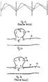
- FIG. 1a the influence of blood pressure on an aneurysm 31 in a blood vessel 30 is illustrated.
- the arrows therein indicate the transmission of the pressure P from the blood vessel 30 into the aneurysm 31.
- the blood vessel 30 is subject to pressure fluctuations which are generated by the pulsatile blood flow or the pulsating activity of the heart.
- the pressure peaks occur in the so-called systole, i.e. the ejection phase of cardiac activity.
- the pressure in diastole assumes a minimum when the heart chambers fill with blood.
- the influence of the pressure fluctuations on the aneurysm 31 is influenced according to the prior art by the use of a conventional fine-meshed aneurysm stent 40.
- the conventional aneurysm stent 40 is implanted in the area of the aneurysm 31 in the blood vessel 30 ( Figure 1b ).
- the structure of the conventional aneurysm stent 40 influences the blood flow between the blood vessel 30 and the aneurysm 31 so that the pressure P that is transmitted into the aneurysm 31 on the one hand is reduced and on the other hand acts on the aneurysm 31 with a time delay.
- Figure 1c shows clearly the pressure profile in the blood vessel 30 (solid line) and in the aneurysm 31 (dashed line), which is covered by a conventional aneurysm stent 40. From the pressure curves shown, it can be clearly seen that the pressure in the aneurysm 31 rises and falls more slowly than in the blood vessel 30. The pressure curve in the aneurysm 31 therefore becomes flatter overall. The finer the mesh, the more effective the effect. The attenuation of the pressure is desirable, but should not be excessive.
- an aneurysm 31 is influenced by the tangential blood flow or vascular flow F G , as in FIG Figure 2a illustrated.
- the vascular flow F G creates shear stresses at the interfaces between the blood within the aneurysm 31 and the blood within the blood vessel 30, which leads to a vortex flow F W within the aneurysm 31.
- a conventional aneurysm stent 40 as shown in FIG figure 2 B shown, the influence of the shear stress triggered by the vessel flow FG is reduced.
- the eddy flow F W within the aneurysm 31 is thus reduced.
- the reduction in the eddy flow F W has the advantage, on the one hand, that the coagulation in the aneurysm is improved.
- an excessive reduction in the eddy current F W can promote the degeneration of cells in the aneurysm wall 34.
- an exchange of blood between the blood in the aneurysm 31 and the blood vessel 30 is hindered, so that the aneurysm wall 34 may not be adequately supplied with nutrients. If the flow is reduced too much, excessively fast-growing thrombi can form.
- Figure 3a shows the influence of the vascular flow F G on an aneurysm 31 in the untreated state when the aneurysm 31 is arranged in a curve of the blood vessel 30.
- the aneurysm 31 is acted upon directly by the vascular flow F G , the vascular flow F G meeting the aneurysm wall 34 locally in an inflow area 36.
- the vessel flow F G is deflected.
- the aneurysm wall 34 is exposed to an increased pressure load in the inflow area 36.
- a conventional aneurysm stent 40 inserted into the blood vessel 30 offers a resistance for the vascular flow F G , so that the flow portion or blood portion that flows into the aneurysm 31 is reduced.
- a conventional aneurysm stent 40 has the effect of reducing the flow rate into the aneurysm. Specifically, a through flow F D through the aneurysm neck 32 of the aneurysm is reduced. At the same time, the resistance offered by the conventional aneurysm stent 40 to the blood flow or vascular flow F G causes a change in the pressure wave or the pressure profile within the aneurysm, which promotes the degeneration of the cells of the aneurysm wall 34. This applies in particular to stents with a fine-meshed structure, which also have a high degree of bending flexibility and therefore fit well into the curvature of the blood vessel 30 ( Figure 3b ).
- Conventional aneurysm stents 40 with a coarse-mesh structure have a higher radial force, so that the blood vessel 30 is caused to stretch, as in FIG Figure 3c shown. It is true that the stretching of the blood vessel 30 reduces the portion of the vascular flow F G that is passed directly into the aneurysm 31.
- the coarse-meshed structure of such known stents 40 simultaneously allows a high blood flow into the aneurysm 31, especially as a result of shear stresses, so that the load on the aneurysm is great.
- Conventional aneurysm stents 40 are additionally influenced by the periodic changes in blood vessels of the blood vessel 30.
- Figure 4a it is shown that the blood vessel 30 during systole, that is, during a pressure peak in the course of the blood pressure, on the one hand expands radially, that is to say has a widening W, and on the other hand is stretched in the longitudinal direction. In addition to the widening W, a stretching E of the blood vessel 30 also takes place during the systole.
- the widening W and stretching E of the blood vessel 30 causes a tapering R of the conventional aneurysm stent 40
- the great risk of dislocation of the conventional aneurysm stent 40 is increased by the expansion of the vessels and the tapering R.
- the influence on the eddy flow F W in the region of the aneurysm 31 is reduced.
- the effectiveness of the aneurysm treatment 31 is therefore reduced.
- the structure of conventional aneurysm stents 40 exhibits essentially an inverse response during systole.
- Conventional aneurysm stents 40 are known from the prior art which have a large braiding angle, as shown in FIG Figure 5a shown.
- Conventional aneurysm stents 40 with a large braiding angle have the property that they can follow an elongation E of the blood vessel without experiencing a strong taper R.
- the structure of such aneurysm stents 40 is comparatively dimensionally stable in the radial direction (low compliance), so that the pressure transmission from the blood vessel 30 into the aneurysm 31 is also strongly influenced.
- the pressure P in the aneurysm 31 is reduced overall, as in FIG Figure 1c shown.
- Figure 5b shows a conventional aneurysm stent 40 that includes a small braid angle.
- Known stents of this type have an increased flexibility, which, however, has the effect that, when the blood vessel 30 is stretched, a taper R of the conventional aneurysm stent 40 occurs, with the disadvantages described above.
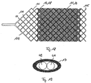
- FIG. 4 is a cross-sectional view of the known aneurysm stent 40 of FIG DE 601 28 588 T2 shown in the compressed state within a delivery system 20.
- the known aneurysm stent 40 has two layers of wire mesh, the wire meshes of the two layers being interwoven.
- a first wire mesh has first wires 41 which have a larger cross-sectional diameter than second wires 42 of a second layer of the conventional aneurysm stent 40.
- the interweaving of the first and second wires 41, 42 results in a complex arrangement of the in the compressed state within the delivery system 20 first and second wires 41, 42 with increased space requirements in the compressed state.
- the stent comprises a tubular body 10.
- the tubular body 10 has a circumferential wall which comprises a first lattice structure 11 and a second lattice structure 12.
- the first and second lattice structures 11, 12 each form separate layers 14, 15 of the peripheral wall.
- the lattice structures 11, 12 of the tubular body 10 according to the invention are therefore independent of one another at least in sections, preferably along the entire lattice structure.
- the grid structures 11, 12 are connected to one another at certain points.
- the peripheral wall of the tubular body can comprise a peripheral line in which the first lattice structure 11 is connected to the second lattice structure 12.
- a single connecting line can be provided between the first lattice structure 11 and the second lattice structure 12, which line extends in the circumferential direction around the tubular body 10. It is explicitly pointed out that the connection between the first lattice structure 11 and the second lattice structure 12 and possibly further lattice structures does not take place over an extended area, but rather essentially linearly.
- FIG. 6b shows a cross section through the tubular body 10, which in the expanded state comprises two layers 14, 15 arranged in the shape of a hollow cylinder (see e.g. Fig. 12 ), each of which has a lattice structure 11, 12.
- an inner layer 15 is provided which has the second lattice structure 12.
- An outer layer 14, which surrounds the inner layer 15, comprises the first lattice structure 11.
- the wires 112 of the first outer lattice structure 11 have a cross-sectional diameter which is smaller than the cross-sectional diameter of the wires 122 of the second inner lattice structure 12.
- the tubular body according to FIG Figure 6b is arranged within a feed system 20. Due to the reduced space requirement of the tubular body 10 compared to conventional aneurysm stems 40, the use of a smaller delivery system 20 is possible. The stent can thus be inserted into smaller blood vessels.
- first lattice structure 11 and the second lattice structure 12 are arranged coaxially one inside the other.
- the first lattice structure 11 and the second lattice structure 12 can also be moved at least in sections relative to one another.
- the first and second lattice structures 11, 12 can be moved relative to one another outside the linear or punctiform connection between the first and second lattice structures 11, 12.
- the relative mobility relates in particular to the individual wires 112, 122 of the first and second lattice structure 11, 12.
- the wires 112 of the first lattice structure 11 can slide on the wires 122 of the second lattice structure 12, and vice versa.
- the wires 112 of the first lattice structure 11 are thicker than the wires 122 of the second lattice structure 12. It is also possible for the wires 112, 122 of the lattice structures 11, 12 to have the same cross-sectional diameter. Furthermore, the wires 122 of the second lattice structure 12 can have a larger cross-sectional diameter than the wires 112 of the first lattice structure 11. For the improved crimpability of the tubular body 10 or, in general, of the stent, it is advantageous if the inner layer 15 consists of a relatively smaller number of thicker wires 122 is formed and the outer layer 14 is constructed by a comparatively higher number of thinner wires.
- one layer 14, 15 has a finer-meshed structure than the other layer 15, 14.
- one of the two layers 14, 15 can comprise more wires 112, 122 than another layer 14
- the wires 112, 122 can be thinner than the wires 112, 122 of the other layer 15, 14.
- the finer-meshed layer 14, 15 has a larger or smaller braiding angle than the comparatively larger-meshed layer 15, 14 having. Combinations of the aforementioned variants are possible.
- the fine-meshed layer forms the outer layer 14 and the coarse-meshed layer forms the inner layer 15.
- the stent preferably has a tubular body 10 comprising an outer layer 14 and an inner layer 15.
- the outer layer 14 is formed by the first lattice structure 11 and the inner layer 15 is formed by the second lattice structure 12.
- the second lattice structure 12 preferably has a coarse-meshed wire mesh.
- the first lattice structure 11, on the other hand, has a fine-meshed wire mesh.
- the coarse-meshed wire mesh of the second lattice structure 12 thus forms a carrier 18, whereas the fine-meshed wire mesh of the first lattice structure 11 forms a network 19.
- both layers that is to say the outer layer 14 and the inner layer 15, to be designed in the same way.
- the layers 14, 15 can therefore have the same fine mesh and / or the same number of wires and / or the same wire thickness and / or the same braiding angle. All combinations of the aforementioned variants are possible.
- the connection of the lattice structures means that they are aligned with one another or have braided patterns that are aligned with one another.
- tubular bodies 10 or stents are also claimed and disclosed in the context of the application, which include a peripheral wall with three or more separate layers. Some or all of the layers can be constructed in accordance with the invention.
- the carrier 18 or the second lattice structure 12 preferably has at most 32, in particular at most 24, in particular at most 20, in particular at most 16, in particular at most 12, in particular at most 8, in particular at most 6, wires 122.
- the wires 122 of the second lattice structure 12 or of the carrier 18 preferably have a cross-sectional diameter of at least 40 ⁇ m, in particular at least 50 ⁇ m, in particular at least 60 ⁇ m, in particular at least 68 ⁇ m, in particular at least 75 ⁇ m, in particular at least 84 ⁇ m, in particular at least 100 ⁇ m. This applies to stents for use in blood vessels 30 which have a cross-sectional diameter of 2 mm to 6 mm.
- the wires 122 of the second lattice structure 12 or of the carrier 18 preferably have a cross-sectional diameter of at least 40 ⁇ m, in particular at least 50 ⁇ m, in particular at least 60 ⁇ m, in particular at least 68 ⁇ m, in particular at least 75 ⁇ m, in particular at least 84 ⁇ m, in particular at least 100 ⁇ m, in particular at least 150 ⁇ m, in particular at least 200 ⁇ m.
- the peripheral wall of the tubular body 10 can comprise more than one carrier 18.
- the carrier 18 or the second lattice structure 12 has a high bending flexibility, the bending of the second lattice structure 12 or the carrier 18 along a longitudinal axis of the second lattice structure 12 requiring a comparatively high bending force or a comparatively high bending moment.
- the carrier 18 thus contributes to a reduction in the flow component flowing directly into the aneurysm 31 of the vascular flow FG. The direct inflow of the vascular flow FG into the aneurysm 31 is thus reduced.
- the carrier 18 can, in the broadest sense, be a support structure or support structure for the network 19. It is preferred here that the carrier 18 is arranged coaxially within the network 19. In this way, the carrier 18 or the second lattice structure 12 for stabilizing the network 19 or the first Lattice structure 11 are used. In particular, the expansion behavior of the network 19 can be controlled by the carrier 18.
- the carrier 18 preferably forms the inner layer 15 of the tubular body 10.
- the carrier 18 can form the outer layer 14.
- Carrier 18 thus achieves good stabilization of blood vessel 30 and expansion of tubular body 10 up to a previously set cross-sectional diameter. Overall, the carrier 18 enables good and controllable expansion of the tubular body 10 and the network within the carrier 18.
- the mesh 19 is preferably more fine-meshed than the carrier 18.
- the mesh 19 thus predominantly takes on the function of influencing the flow in relation to the aneurysm 31.
- the fine mesh of the mesh 19 is preferably limited so that the inflow of blood into the aneurysm 31 is not complete is prevented. Rather, the aim of the mesh 19 is to avoid a rupture of the aneurysm 31 on the one hand and to maintain a sufficient supply of nutrients and mechanical loading of the aneurysm wall 34 on the other hand, so that degeneration of the cells of the aneurysm wall 34 is avoided.
- the network 19 at most 48, in particular at most 44, in particular at most 40, in particular at most 36, in particular at most 32, in particular at most 24, in particular at most 20, in particular at most 16, in particular at most 12, Includes wires 112.
- the network 19 is stabilized by the carrier 18, so that there are no special requirements for the network 19 with regard to the radial force.
- the wires 112 of the first lattice structure 11 or of the network 19 preferably have a cross-sectional diameter of at most 77 ⁇ m, in particular at most 51 ⁇ m, in particular at most 46 ⁇ m, in particular at most 41 ⁇ m, in particular at most 36 ⁇ m, in particular at most 26 ⁇ m, in particular at most 20 ⁇ m on.
- the wires 112 of the first lattice structure 11 or of the network 19 have a cross-sectional diameter of at most 155 ⁇ m, in particular at most 105 ⁇ m, in particular at most 77 ⁇ m, in particular at most 51 ⁇ m, in particular at most 46 ⁇ m, in particular at most 41 ⁇ m, in particular at most 36 ⁇ m, in particular at most 26 ⁇ m, in particular at most 20 ⁇ m.
- the net 19 preferably forms the outer layer 14 of the tubular body 10.
- the highly flexible net 19 is supported by the carrier 18 or is forced into the expanded state during the expansion of the tubular body 10.
- the interaction between carrier 18 and net 19 prevents the net 19 from folding sufficiently in the blood vessel 30.
- the carrier 18 forming the inner layer 15 preferably supports the net 19 over the entire length of the net 19.
- the first lattice structure 11 and the second lattice structure 12 are connected to one another at points.
- the first lattice structure 11 is preferably connected to the second lattice structure 12 at a proximal end of the tubular body 10.
- the first lattice structure 11 has a proximal end 110 which is connected to a proximal end 120 of the second lattice structure 12.
- elements arranged proximally are arranged closer to the user than distal elements.
- the first lattice structure 11 and the second lattice structure 12 preferably each have an obliquely tapering proximal end 110, 120.
- the wires 112, 122 of the first lattice structure 11 and the second lattice structure 12 converge at the inclined proximal ends 110, 120.
- the converging wires 112, 122 are connected to one another. Such a connection of the first and second lattice structures 11, 12 is exemplified in FIG Figure 8 shown.
- the connection of the converging wires 112, 122 of the first lattice structure 11 and the second lattice structure 12 takes place according to the exemplary embodiment according to FIG Figure 8 by a connecting sleeve 17.
- the Converging wires 112, 122 of the first and second lattice structures 11, 12 can run parallel to one another in the region of the connecting sleeve 17 or can be twisted with one another. Furthermore, it can be provided that the wires 112 of the first lattice structure 11 completely enclose the wires 122 of the second lattice structure 12 in the region of the connecting sleeve 17. This essentially corresponds to the arrangement as shown in the cross-sectional view Figure 6b shown. Conversely, it is also possible for the wires 122 of the second lattice structure 12 to completely enclose the wires 112 of the first lattice structure 11 in the region of the connecting sleeve 17. Other types of connection are possible.
- first lattice structure 11 and the second lattice structure 12 or the mesh 19 and the carrier 18 can be connected to one another in a central region of the tubular body 17.
- a connection between the first and second lattice structure 11, 12 between the net 19 and the carrier 18 at a distal end of the tubular body 10 is conceivable, for example. on the loops of the lattice structure.
- a connection in the inclined area is possible.
- the lattice structures 11, 12 preferably have a wire mesh which has an oblique course at a proximal end 110, 120 or generally at an axial end of the respective lattice structure 11, 12.
- wire meshes are in the post-published DE 10 2009 056 450 A1 which can be traced back to the applicant and which is incorporated in full into the present application by reference.
- the braiding angle of the individual wire braids or lattice structures 11, 12 is expedient.
- Preferred embodiments for different braiding angles are described below: In conventional aneurysm stents 40, it is provided that the braiding angle is selected to be as large as possible so that the aneurysm neck 32 is closed as much as possible.
- the disadvantage of such treatment options is an increased risk of bleeding due to the degeneration of the cells of the aneurysm wall and the formation of enlarged fresh thrombi, high foreshortening, which is a positioning of the conventional one Aneurysm stents 40 made difficult and insufficient adaptation to variable vessel diameters.
- the change in length of a conventional aneurysm stent with a change in diameter is greater, the greater the braiding angle selected. This makes a reproducible and adjustable configuration of known aneurysm stents 40 difficult.
- the braiding angle is limited.
- the braiding angle is at most 70 °, in particular at most 67 °, in particular at most 65 °, in particular at most 63 °, in particular at most 60 °.
- the braiding angle refers to the acute angle that is formed between a wire of the lattice structure and the longitudinal axis of the tubular body 10. It was found that at a braiding angle of 60 °, a shortening of the respective lattice structure 11, 12 during expansion, i.e. takes place in the transfer of the tubular body 10 from a compressed state to an expanded state, in the amount of 50%.
- the lattice structure 11, 12 with a braiding angle of 60 ° which has a length in the compressed state, i.e. within the feed system 20, of 40 mm, in the expanded state, in particular in the blood vessel 30, a length of 20 mm or something covers more than 20mm.
- a braiding angle is preferably provided for the first lattice structure 11 or the second lattice structure 12 which is at most 60 °, in particular at most 59 °, in particular at most 58 °, in particular at most 57 °, in particular at most 56 °, in particular at most 55 °, in particular at most 54 ° , in particular at most 53 °, in particular at most 52 °, in particular at most 51 °, in particular at most 50 °, in particular at most 45 °.
- What is achieved thereby is that the shortening of the tubular body 10 moves into an acceptable range when it is expanded or released into a blood vessel 30. The foreshortening effect is thus reduced. Since the tubular body 10 is usually oversized, i.e.
- the tubular Body 10 has a comparatively good flexibility.
- dimensional information for the stent in particular the tubular body 10 in the context of the application, basically relates to the manufacturing state, unless otherwise stated.
- the first lattice structure 11 and the second lattice structure 12 or the mesh 19 and the carrier 18 can have different braiding angles. What is achieved thereby is that different foreshortening effects occur during the expansion of the tubular body 10.
- the carrier 18 and the net 19, which have different braiding angles have different shortening behavior when the tubular body 10 is discharged from a feed system 20. This also applies in the implanted state when blood pressure fluctuations act on the tubular body 10 as a result of the pulsatile blood flow.
- the two layers 14, 15, that is to say the carrier 18 and the mesh 19, are thus influenced differently by the pulsatile blood flow.
- a gap 16 is formed between the carrier 18 and the mesh 19 or between the outer layer 14 and the inner layer 15, in particular between the first lattice structure 11 and the second lattice structure 12.
- the gap 16 can act as a cushion.
- the gap is created, for example, by the fact that the braids are connected selectively in one area and have different braiding angles in at least one area. The braiding angle can vary along the longitudinal axis.
- the braiding angle of the carrier 18 is smaller than the braiding angle of the net 19. This causes the net 19 to shorten more than the carrier 18 when it is released from a feed system. This simplifies the positioning of the tubular body 10 overall since the carrier 18 shows a slight foreshortening effect upon expansion.
- the tubular body 10 is discharged from a delivery system 20 in which the delivery system with the compressed tubular body 10 is delivered to the treatment site. The delivery system 20 is then pulled in the proximal direction, whereas the tubular body 10 is held stationary.
- a proximal end of the tubular body 10 to be pushed slightly in the distal direction at the same time as the proximal movement of the feed system 20. This prevents the outer layer 14 of the tubular body 10 is pulled along the vessel wall 35 of the blood vessel 30 and causes an injury to the vessel wall 35.
- the fact that the carrier 18 has a smaller braiding angle than the mesh 19 ensures that when the tubular body 10 expands, the proximal end 120 of the second lattice structure 12 or of the carrier 18 is pushed only a small amount in the distal direction against the foreshortening got to. The positioning of the tubular body 10 or the multi-layer stent is thus facilitated.
- outer element or the outer lattice structure can have a smaller foreshortening than the inner element or the inner lattice structure, so that the outer element rests well against the vessel wall.
- FIG 9 the release of the tubular body 10 from a delivery system 20 into a blood vessel 30 is shown.
- the distal end 115 of the first lattice structure 11 and the distal end 125 of the second lattice structure 12 initially unfold simultaneously or at the same height.
- the further retraction of the feed system 20 in the proximal direction causes a relative movement between the first lattice structure 11 and the second lattice structure 12, since with further discharge of the tubular body 10 the foreshortening effect of the first lattice structure 11 is more pronounced than in the second lattice structure 12 a proximal displacement of the net 19 relative to the carrier 18 takes place.
- the net 19 is preferably arranged on the outside of the carrier 18.
- the network 19 thus forms the outer layer 14 of the peripheral wall of the tubular body 10.
- the net 19 forms the inner layer 15 and the carrier 18 forms the outer layer 14. This has the advantage that the mesh 19 can slide on wires 122 of the carrier 18 during expansion.
- the externally arranged net 19 has a smaller braiding angle than the carrier 18 and thus also a smaller foreshortening effect than the carrier 18.
- the contact between the tubular body 10 and the vessel wall 35 of the blood vessel 30 is initially through the mesh 19.
- the lattice structures 11, 12 or the proximal end of the tubular body 10 pushed in the distal direction.
- the inner carrier 18 or the inner layer 15 moves in the distal direction.
- the carrier 18 can slide along the vessel wall 35. Since the carrier 18 has a relatively small braiding angle, it is possible to push the carrier 18 along the vessel wall 35 without the carrier 18 or the second lattice structure 12 being compressed.
- the wires 122 of the second lattice structure 12 or of the carrier 18 have a directional component that is particularly pronounced in the longitudinal direction, that is, parallel to the longitudinal axis, of the tubular body 10.
- sliding the carrier 18 or the second lattice structure 12 does not necessarily lead to a change in the angle of incidence or braiding angle of the wires 122 of the second lattice structure 12.
- the small braiding angle of the carrier 18 compresses the carrier 18 when the Carrier 18 avoided.
- the carrier 18 or the second lattice structure 12 After complete expansion of the tubular body 10, the carrier 18 or the second lattice structure 12 has a greater longitudinal extent than the net 19 or the first lattice structure 11.
- the net 19 is therefore subject to a greater foreshortening effect than the carrier 18, so that the carrier 18 is not completely covered in the expanded state of the tubular body 10, but only partially or in sections with the mesh 19 ( Figure 10 ).
- the net 19 is longer in the compressed state than the carrier 18. In the expanded state, the length of the net 19 and the carrier 18 can correspond or the difference in length can be reduced.
- the first lattice structure 11 and the second lattice structure 12 or the mesh 19 and the carrier 18 behave differently when the vessel pulsates.
- a gap 16 can form between the first lattice structure 11 and the second lattice structure 12 or between the mesh 19 and the carrier 18, in particular during systole.
- the foreshortening effect causes the Carrier 18, which has a comparatively small braiding angle, is tapered at least in sections or shows a taper R at least in sections.
- the network 19 however, has no or at least a significantly smaller taper R during the systole and the stretching E of the blood vessel.
- a gap 16 or an interspace or cushion is thus created between the carrier 18 and the net 19.
- the behavior of the lattice structures 11, 12 or the carrier 18 and the net 19 with different braiding angles when the blood vessel is stretched E is shown in FIG Figure 11 shown.
- the network 19 is preferably adapted in such a way that the network 19 can follow the pulsation of the blood vessel 30.
- the net 19 has increased mobility compared to the carrier 18, which can be achieved, for example, by means of correspondingly small wire diameters and / or a corresponding setting of the braiding angle.
- a through flow F D is produced , blood flowing from the blood vessel 30 into an aneurysm 31 and leading to an increase in volume in the aneurysm 31.
- the high expandability of the network 19 enables a section of the network 19 to move radially outward or to be deflected radially outward, the network 19 following the blood movement in sections.
- a flow of blood through the mesh of the net 19 is hindered.
- the expandability of the mesh 19 is preferably set in such a way that the mesh 19 has an inertia or a resistance to the blood flow in terms of its deflection by the blood flow into the aneurysm 31.
- the network 19 thus follows the rise in blood pressure during systole by means of a radial outward movement.
- the blood flow through the meshes of the net 19 into the aneurysm 31 is reduced at the same time.
- the radial deflection of the network 19 under the influence of the systolic blood pressure increase is shown in FIG Figure 12 shown.
- the pressure transfer only takes place up to a certain degree, so that clots form and less degeneration of the cells occurs.
- the ability to adjust the expandability of the network 19, for example by choosing the braiding angle allows the pressure transmission to be regulated.
- the deflection of the network 19 into the aneurysm 31 has several advantages.
- the flexible network 19 enables the pressure wave to be transmitted into the aneurysm. It is true that blood flow into the aneurysm is impeded. In contrast, the pressure P is transmitted into the blood volume of the aneurysm 31. As a result, a periodic load on the cells of the aneurysm wall 34 is maintained, whereby a degeneration of the cells is counteracted.
- the direct blood flow that is, the throughflow F D, is reduced, as a result of which the endotelialization of the tubular body 10 is promoted.
- the settlement of endotel cells and adhesion of the endotel cells to the tubular body 10 is facilitated by the reduced through flow F D.
- the overgrowth of the meshes of the lattice structures 11, 12 is facilitated since there is no or only a slight through flow F D through the meshes of the first lattice structure 11 or of the network 19.
- a lattice structure which is flexible in such a way that it can be deflected into the aneurysm 31 at least in sections.
- This is made possible, for example, by a lattice structure that has a comparatively small braiding angle.
- a lattice structure experiences an increased taper R when the blood vessel 30 is subject to an elongation E, for example as a result of the pulse beat.
- Lattice structures with a large braiding angle do not show this effect.
- a lattice structure with a large braiding angle enables a high degree of elongation without a significant change in the cross-sectional diameter.
- such lattice structures do not permit any bulging in sections, for example into an aneurysm 31.
- the stent according to the invention both effects are achieved, the functions being assigned to different lattice structures 11, 12.
- the second lattice structure 12 or the carrier 18 enables the tubular body 10 to be precisely and reliably positioned in the blood vessel.
- the network 19, on the other hand, enables the blood flow into the aneurysm 31 to be influenced, and at the same time a transmission of the blood pressure is made possible. The postoperative risk of rupture of the aneurysm 31 is thus reduced.
- the mesh 19 or the first lattice structure 11 having different braiding angles.
- the first lattice structure 11 comprises a middle section 111 and two edge sections 116, the middle section 111 being arranged between the edge sections 116.
- the first lattice structure 11 has a smaller braiding angle than in the edge sections 116.
- the comparatively larger braiding angle in the edge sections 116 results in the edge sections 116 extending the extension E of the blood vessel 30 compensate, because they can be stretched without a significant change in diameter.
- transition sections 113 are formed between the central section 111 and the edge sections 116, which are indicated by the dotted lines in FIG Figure 7 are highlighted.
- a shortening K takes place in the transition sections 113, which is oriented in the opposite direction to the elongation E of the blood vessel 30.
- the middle section 111 is more expandable than the edge sections 116, so that the middle section 111 can have a greater shortening under the influence of a systolic blood pressure increase than the edge sections 116.
- the middle section 111 can therefore follow the increase in blood pressure, so that the network 19 or the first lattice structure 11 in the middle section 111 can bulge into the aneurysm 31 or form a bulge B.
- the carrier 18 or the second lattice structure 12 is shown in FIG Figure 7 not shown.
- the network 19 has a shorter longitudinal extent than the carrier 18.
- the mesh 19 or the first lattice structure 11 has a substantially shorter longitudinal extent than the carrier 18 or the second lattice structure 12.
- the tubular body 10 is preferably positioned in the blood vessel 30 in such a way that the distal end 115 of the first lattice structure 11 or of the mesh 19 is arranged in the region of the aneurysm neck 32.
- the distal end of the first lattice structure 115 forms a free end.
- the proximal end 110 of the first lattice structure 11 is connected to the proximal end 120 of the second lattice structure 12.
- the free end or distal end 115 of the first lattice structure 11 can expand radially outward.
- the distal end 115 of the first lattice structure 11 or of the network 19 is deflected radially outward into the aneurysm 31 or into the region of the aneurysm neck 32.
- the network 19 can be deflected into the aneurysm 31 in sections.
- the net 19 therefore moves into the aneurysm 31 with the rise in blood pressure, so that the throughflow F D through the meshes of the net 19 are reduced.
- the distal end is longer and secures the attachment.
- FIG. 14 Another embodiment is shown in Figure 14 shown, wherein the tubular body 10 comprises a peripheral wall having an inner layer 15 and an outer layer 14.
- the inner layer 15 is through the second Lattice structure 12 is formed, which is designed as a carrier 18.
- the outer layer 14 has the first lattice structure 11 and a third lattice structure 13, the first lattice structure 11 and the third lattice structure 13 each forming a network 19.
- the first and third lattice structures 11, 13 are each connected with their proximal ends 110, 130 to the second lattice structure 12.
- the distal ends 115, 135 of the first lattice structure 11 and the third lattice structure 13 are arranged freely.
- the proximal end 130 of the third lattice structure 13 is connected to the second lattice structure 12 essentially at the level of the distal end 115 of the first lattice structure 11. This essentially results in a scale-like arrangement of the first and third lattice structures 11, 13.
- the first lattice structure 11 and the third lattice structure 13 can also overlap at least in sections or be arranged at a distance.
- the first lattice structure 11 and the third lattice structure 13 or the nets 19 can have a flap-like function. Due to the free mobility of the distal ends 115, 135, the nets 19 or the first and third lattice structures 11, 13 enable a certain pressure transfer into the aneurysm 31. At the same time, the valve function of the nets 19 enables additional treatment devices to be fed into the aneurysm 31 Treatment devices can include a coil catheter 21, for example.
- the invention is not restricted to two nets 19 or two lattice structures 11, 13 which form the outer layer 14. Rather, it is also provided within the scope of the invention that three or more nets 19 or lattice structures 11, 13 form the outer layer 14 of the peripheral wall of the tubular body 10.
- Figure 15a a further embodiment is shown, which differs from the embodiment according to Figure 14 differs in that the first lattice structure 11 and the third lattice structure 13 are oriented essentially in opposite directions.
- the first lattice structure 11 comprises a proximal end 110 which is connected to the proximal end 120 of the second lattice structure 12.
- the distal end 115 of the first lattice structure 11 is arranged freely.
- the third lattice structure 13 comprises a distal end 135 which is connected to the distal end 125 of the second lattice structure 12.
- the proximal end 130 of the third lattice structure 13 is arranged freely.
- the nets 19 or the first and third lattice structures 11, 13 overlap in the expanded state, but are arranged in alignment with one another in the compressed state of the tubular body 10.
- the carrier 18 or the second lattice structure 12 is shortened to a greater extent than the nets 19 during the expansion of the tubular body 10.
- At least one netting 19 or several nets 19 in particular have a smaller braiding angle than the carrier 18, so that the carrier 18 is greatly shortened during the expansion of the tubular body 10, whereby the overlap of the nets 19 occurs in the expanded state. The overlap ensures that the aneurysm neck 32 is completely covered.
- the mobility of the free ends of the first and third lattice structures 11, 13 enables the two lattice structures 11, 13 or nets 19 to move relative to one another, so that an efficient pressure transmission into the aneurysm 31 is made possible.
- the overlapping of the first and third lattice structures 11, 13 in sections increases the fine mesh in the area of the aneurysm neck 32 and advantageously influences the blood flow into the aneurysm 31.
- a comparatively larger feed system 20 is required.
- This increases the fine mesh of the individual nets 19 or of the first and third lattice structures 11, 13.
- Such a configuration has the effect that the nets 19 are greatly shortened during expansion.
- the carrier 18 or the second lattice structure 12, on the other hand advantageously has a comparatively small braiding angle, so that the foreshortening effect is reduced.
- the first lattice structure 11 and the third lattice structure 13 or the two nets 19 are preferably arranged in alignment with one another.
- the free ends of the first and third lattice structures 11, 13 can touch each other, so that the aneurysm 31 or the aneurysm neck 32 is completely covered by the first and third lattice structure 11, 13.
- the first and third lattice structures 11, 13 are superimposed, as in FIG Figure 16b shown.
- the nets 19 or the first and third lattice structures 11, 13 are provided for the nets 19 or the first and third lattice structures 11, 13 to have a small number of wires. Due to the comparatively large braiding angle which the first and third lattice structures 11, 13 assume in the blood vessel 30, a high degree of fine mesh is ensured even with a small number of wires. Furthermore, the cross-sectional diameter in the compressed state of the tubular body 10 is reduced by the small number of wires.
- the nets can also be arranged inside.
- the setting of different braiding angles in separate layers 14, 15 of the tubular body enables the formation of a gap 16 between the layers 14, 15.
- the mesh 19 can lift off the carrier 18 when the tubular body 10 is expanded.
- the formation of a gap in a suitably configured stent is shown in FIG Figure 17 shown.
- the gap 16 enables the flow conditions in the aneurysm 31 to be additionally influenced.
- the gap 16 or the distance between the mesh 19 and the carrier 18 essentially creates a cushion in which flow eddies occur that are caused by shear stresses between the blood within the cushion or . Gap 16 and the vessel flow F G are effected.
- the vascular flow F G does not cause a direct eddy flow F W in the aneurysm, but rather flow eddies in the gap 16.
- the expandability of the network 19 enables pressure to be transmitted into the aneurysm 31, so that, to maintain the cells of the aneurysm wall 34, on the one hand nutrients reach the cells via the blood and on the other hand mechanical stress is maintained that counteracts degeneration.
- the network can enable reduced or moderate pressure transmission.
- FIG Figure 18 An embodiment of an overall system or a stent with carrier 18 and mesh 19 is shown in FIG Figure 18 shown.
- the stent according to Figure 18 forms a retractable braid due to the sloping tip in the proximal area of the stent.
- the stent is in particular an aneurysm mast.
- the basic structure of the stent, in particular in the area of the inclined tip, is the same as that of the applicant DE 10 2009 056 450 disclosed.
- the basic structure is a mesh of wire elements with a series of end meshes or end loops that delimit an axial mesh end, the end meshes comprising outer wire elements that form a terminating edge 46 of the mesh and merge into inner wire elements that are inside the mesh are arranged.
- a first section of the terminating edge 46 and a second section of the terminating edge 46 each have a plurality of outer wire elements which together form a circumferential edge of the terminating edge 46.
- the edge is adapted in such a way that the axial braid end of the hollow body can be drawn into a feed system.
- the outer wire elements of the first section for forming the terminating edge 46 are arranged directly after one another and each have a first axial component which runs in the longitudinal direction of the hollow body.
- the outer wire elements of the second section for forming the terminating edge 46 are arranged directly downstream of one another along this and each have a second axial component which runs in the longitudinal direction of the hollow body and is opposite to the first axial component. Both axial components are related to the same direction of rotation of the edge.
- This structure of the proximal end of the stent applies to all exemplary embodiments of this application in which the stent has an inclined tip pointing in the proximal direction.
- the first lattice structure 11 of the network 19 is congruent, ie arranged congruently over the second lattice structure 12 of the carrier 18.
- the second lattice structure 12 of the carrier 18 is therefore only visible in the area of the net 19 where the strands or individual wires of the two lattice structures 11, 12 are not congruent.
- the strands or wires of the second lattice structure 12 of the carrier 18 are marked black in the area of the net 19 and have a larger diameter than the wires of the net 19.
- the two lattice structures 11, 12 are congruent, so that only the Figure 18 first lattice structure 11 shown above is visible.
- the second lattice structure 12 is arranged under the first lattice structure 11 in the developed illustration.
- the first lattice structure 11 with the mesh 19 is arranged radially on the outside and the second lattice structure 12 of the carrier 18 is arranged radially on the inside.
- the transition from the network 19 to the strands in the area of the tip of the first lattice structure 11 takes place in such a way that four individual wires of the network 19 or four individual strands of the network 19 are combined to form two strands, which in turn are combined into one strand in the proximal direction , from which the lattice structure of the tip is formed.
- a different number of wires or strands, each of which are successively combined or combined with one another, is possible.
- the strands guided in the proximal direction run into the terminating edge 46 and are there according to FIG DE 10 2009 056 450 connected.
- the area of the tip of the carrier 19 is constructed accordingly, the lattice structure 12 of the carrier 18 being formed from individual wires with a larger diameter than the individual wires of the first lattice structure 11.
- the second lattice structure 12 can also be formed from several strands, each consisting of individual wires.
- the strands or wires of the two lattice structures 11, 12 run parallel and are congruent. The same applies to the distal end 115.
- the wires or strands also run parallel, but are not congruent. Rather, the wires of the network 19 overlap the grid cells formed by the carrier 18.
- the punctiform connection between the first lattice structure 11 and the second lattice structure 12 takes place in accordance with the exemplary embodiment Figure 18 outside the two lattice structures 11, 12.
- the two lattice structures 11, 12 are connected in the area of the two common end strands 43, 44 in which all the wires of the respective lattice structures 11, 12 are brought together.
- the two end strands 43, 44 are in Figure 19 shown in cross section.
- the connection is made by the sleeve 17. Instead of the sleeve 17, the two end strands 43, 44 can be connected in some other way.
- the thicker wires of the carrier 18 are twisted in an inner strand.
- the thinner wires of the net 19 or the first lattice structure 11 are twisted radially on the outside on the inner strand.
- Other types of connection are possible.
- the wires can be connected by a sleeve, for example by the sleeve 17 according to FIG Figure 19 .
- the sleeve can be crimped onto the wires and / or welded to the wires.
- the wires can be twisted and connected as described above.
- the wires can also be arranged loosely next to one another.
- the strands of both lattice structures 11, 12 can also be arranged side by side, with the sleeve 17 enclosing and connecting both strands, as in FIG Figure 19 shown.
- the sleeve 17 can be circular or oval in cross section, as in the example according to FIG Figure 19 shown. The oval contour favors apposition to the vessel wall.
- the punctual connection of the two lattice structures 11, 12 outside the area of the lattice structures 11, 12 ensures that the lattice structures 11, 12 are loosely arranged one above the other and are therefore movable relative to one another.
- the two lattice structures 11, 12 are aligned so that the Patterns of the lattice structures 11, 12 in combination with one another form a superordinate common pattern, as in FIG Figure 18 good to see.
- connection between the two lattice structures 11, 12 or the two braids can also take place in the area of the loops.
- the thin wires of the network 19 can be wound around the thicker wires of the carrier 18 or twisted with them. This applies to any number of wires.
- each loop of the net 19 consists of two wires which are wound around the single wire of the loop of the carrier 18. A different number of wires or wire combinations is possible.
- the connection of the wires through sleeves is also possible.
- connection is made only in the area of the terminating edge 46, for example by twisting.
- a further point connection can be achieved in that the wires of the two lattice structures 11, 12 are twisted or otherwise connected, for example welded, in the entire inclined area or in the entire area of the tip.
- the distal end can correspondingly have a point connection between the two lattice structures 11, 12.
- FIG Figure 21 Another embodiment of a stent according to the invention is shown in FIG Figure 21 shown, in which a carrier 18 according to Figure 20 is used.
- the carrier 18 according to Figure 20 is adapted to be connected in a central area with a further mesh, in particular a further lattice structure.
- the second lattice structure 12 of the carrier 18 has fixed anchoring points 45 to which the first lattice structure 11 can be attached to the net 19.
- the basic structure of the lattice structure 12 of the carrier 18 corresponds to the basic structure according to FIG Figure 18 or. DE 10 2009 056 450 , at least as far as the tip area is concerned.
- the wires of the carrier 18 are twisted and run essentially parallel to the longitudinal axis of the stent.
- the combined structure is in Figure 21 shown, the first lattice structure 11 with the network 19 in the tubular (three-dimensional) body 10 being arranged radially on the outside and the carrier 18 being arranged radially on the inside.
- the first lattice structure 11 with the net 19 partially overlaps the second lattice structure 12, with no overlap taking place in the region of the tip or terminating edge 46. That's why in Figure 21 the lattice structure 12 of the carrier 18 is visible in the area of the tip.
- the lattice structure 12 of the carrier 18 continues in the area of the net 19 and is clearly visible under the net 19 through the thicker wires or strands, which are marked in black.
- the end loops of the first lattice structure 11 cover the distal end of the second lattice structure 12 of the carrier 18.
- the point connection of the two lattice structures 11, 12 takes place in that the wires of the net structure 19 converge in the area of the twisted elements of the carrier or the fixed anchoring points 45.
- the wires of both lattice structures 11, 12 run parallel to one another and are oriented parallel to the axis of the stent.
- the wires can be twisted or otherwise connected in the area of the fixed anchoring points 45, for example by welding, gluing, soldering or by a separate means, such as a connecting sleeve, in particular a C-shaped connecting sleeve.
- the C-shaped connecting sleeve has the advantage that the two systems or lattice structures 11, 12 can initially be overlapped during manufacture and then connected by the sleeve.
- the thicker wires of the carrier 18 can be wrapped around or twisted with the thinner wires of the net 19, specifically in the area of the fixed anchoring points 45.
- connection can also be made at crossings of the carrier 19.
- the connection of the two lattice structures 11, 12 takes place at points, ie not over the entire area of the two lattice structures, but only in a limited area.
- the selective connection according to Figure 21 it is a line connection in the circumferential direction, which is composed of individual connection points or connection points.
- the connection points are formed, for example, at the fixed anchorage points 45, where the two lattice structures are connected to one another in a locally limited manner.
- the distal end of the mesh 19 can have open ends. The advantage here is that it is easy to manufacture.
- the distal end can also have closed loops.
- a point connection can also be made at the distal end of the network.
- the invention is suitable for endovascular interventions, in particular for the treatment of aneurysms in blood vessels.
- the invention is not limited to a stent that comprises braided lattice structures. Rather, the lattice structures can also be formed by cutting a corresponding structure from a solid material, in particular a tubular solid material.
- wire mesh or wire mesh is advantageous with regard to the preferred high degree of fine mesh.
- the multiple braid with the outer braid or outer layer 14 that is relatively movable in the axial - and radial - direction is suitable for treating different types of aneurysms.
- the multiple braid is suitable for the treatment of fusiform aneurysms, which develop in a spindle-shaped manner over the entire circumference of the vessel.
- the inner layer 15 or the second lattice structure 12, as described above forms the carrier 18 which positions the system in the vessel.
- the inner layer 15 lies, as in FIG Fig. 22 shown, upstream and downstream of the aneurysm 31 to be treated on the vessel wall 35.
- the outer layer 14 expands evenly over the entire circumference of the tubular body 10 and stands out from this, as in FIG Fig. 22 shown. As a result, an annular gap 16 is formed in the area of the fusiform aneurysm, which ensures the turbulence of the blood flow in this area.
- the locally limited attachment of the outer layer 14 on the one hand and the low rigidity of the outer layer 14 on the other hand enable the spindle-shaped expansion of the outer layer 14 so that the outer layer 14 protrudes at least partially into the fusiform aneurysm.
- the possibilities of locally limited fastening are described above and are disclosed in connection with this exemplary embodiment.
- the rigidity of the outer layer 14 is less than the rigidity of the inner layer 15.
- the outer layer 14 is more flexible than the inner layer 15.
- the outer layer 14 moves laterally away from the inner layer 15, as for example in FIG Fig. 12 shown.
- the outer layer 14 is thus pressed away from the side on which there is no aneurysm and bulges into the neck of the aneurysm.
- the bulging or expansion of the outer layer 14 or of the outer braid can be set automatically by appropriate conditioning as part of a heat treatment when the tubular body 10 is released from the catheter.
- the expansion of the outer braid can be impressed on a central area of the outer braid or only be impressed on a central area of the outer braid.
- the shape of the expansion can be, as in Fig. 22 shown, be adapted for the treatment of a fusiform aneurysm and extend annularly around the tubular body 10 or have a spindle shape.
- the shape of the widening can be adapted to the treatment of a saccular aneurysm and can only develop laterally or only on one side of the body 10.
- the outer layer 14 or the outer braid can for example be formed on a correspondingly curved mandrel and heat-treated.
- the braid ends or the end regions of the braid of the outer layer 14 remain in contact with the braid of the inner layer 15. This means that the end regions of the outer layer 14 are on the same plane or the same jacket surface as the braid of the inner layer 15. In the middle area or generally between the end regions, the braid of the outer layer 14 stands out from the inner layer 15.
- the expansion as described above, can result from the different braiding angle between the inner layer 15 and the outer layer 14 or between the respective braids.
- the above-described forced expansion of the outer layer 14 by a corresponding heat treatment is disclosed and claimed as a possible option in connection with all exemplary embodiments.
- at least the outer layer 14 or the braid of the outer layer 14 is made of a shape memory material, for example nitinol or another shape memory material commonly used in the field of medical technology that enables a heat-induced change in shape.
- the forced change in shape can also be achieved by elastic deformation of the braid of the outer layer 14.
- the braid of the outer layer 14 or the outer braid can stand out from the inner layer 15 because the outer layer 14 is relatively soft or more flexible than the inner layer 15 and can move in the flow.
- the braid of the outer layer 14 can have a stable structure.
- the braid of the outer layer 14 can have reinforcing wires that restrict the radial mobility of the braid of the braid of the outer layer 14.
- a stable gap is formed between the outer layer 14 and the inner layer 15, the braid of the outer layer 14 not moving or only slightly moving in the blood flow.
- the radial stability or rigidity of the outer layer 14 roughly corresponds to the radial stability or rigidity of the inner layer 15.
- the stable outer braid or the stable outer layer 14 is particularly suitable in connection with the embodiment described above, in which the shape of the outer layer 14 is curved radially outward in the resting state or in which the curvature is impressed outward and the gap 16 between the outer layer 14 and the inner layer 15 is formed automatically when discharged from the catheter.
- the automatic formation of the gap 16 generally means that the expansion of the outer layer 14 is brought about by internal forces or at least predominantly by internal forces of the outer layer 14. This process can be supported by the external forces applied by the blood flow. In this embodiment, however, the expansion is primarily due to the properties of the shape memory material and the associated internal forces.
- FIG 23 Another embodiment of the invention is shown in which the braid of the outer layer 14 or generally the outer layer 14 has a contour that is undulating in cross section.
- the distance between the outer and inner layers 14, 15 varies, with the distance alternately increasing and decreasing.
- the wave-shaped contour particularly effectively slows down the flow in the aneurysm 31.
- the wave-shaped structure can have at least two wave crests or peaks and a wave trough lying between them.
- four peaks of the wave-shaped contour are formed. A different number of peaks or wave crests is possible. As in Fig. 23 you can see that the wave crests are of different heights.
- the height of the wave crests decreases.
- the wave crests are highest in the middle area of the wave-shaped contour.
- the outer contour of the wave crests which is determined by their peaks or the sections furthest away from the inner layer 15, corresponds approximately to the shape of the aneurysm to be treated.
- the outer contour (envelope surface) of the wave-shaped contour is adapted to the shape of the aneurysm.
- the wave troughs can be at least partially spaced from the inner layer 15. All of the wave troughs can be spaced from the inner layer 15. Alternatively, the wave troughs can at least partially touch the inner layer 15. All wave troughs can touch the inner layer 15.
- the contact points between the wave troughs and the inner layer 15 can be produced by connections between the braids of the outer layer 14 and the inner layer 15. This applies to a part of the wave troughs or to all wave troughs.
- the braid of the outer layer 14 can be connected to the braid of the inner layer 15 at some points that are spaced apart from one another in the axial direction. This can be achieved, for example, by sleeves, crimp sleeves or by other connection techniques, for example material connections.
- the sleeves can for example be C-shaped and subsequently, i. after braiding to connect the two braids or multiple braids.
- the wave-like structure can be preconditioned by a heat treatment so that the wave-like structure is established in the state of rest.
- a known per se Shape memory material such as nitinol is used.
- a purely mechanical shape is possible, with the waveform stretching in the catheter and returning to the wave-like state of rest upon discharge.
- a particularly important refinement of this exemplary embodiment, to which the invention is not restricted, is that those areas that are intended to expand radially outward have a different braided structure than those areas of the wave-shaped contour or the wave-shaped structure that form the wave troughs form, in particular those areas which are to remain in contact with the braid of the inner layer 15.
- the braiding angle in the areas that are intended to stand out, in particular in the area of the wave crests can be smaller than the braiding angle of the areas that are not intended to stand out, in particular in the area of the wave troughs.
- a braid that has a relatively small braid angle can be expanded comparatively easily. When expanding, the braid angle increases due to the axial compression when expanding.
- the braiding angle can be greater than 45 ° in the region of the wave troughs and less than 45 ° in the region of the wave crests.
- the areas with a small braiding angle or smaller braiding angle than in other areas are associated with a smaller axial shortening during expansion. This means a greater radial expansion with less axial compression. This means that when the inner layer is axially compressed, the areas with the small braiding angle (wave crests) have to expand outwards so that the structure is also shortened.
- the outer layer actually has to shorten if it is connected distally to the inner layer or if the inner layer presses it outwards against the vessel wall and therefore blocks it.
- the wave-shaped structure can result from a combination of heat treatment (pre-embossing of the contour) and / or different braiding angles and / or mechanical connections between the inner and outer layers 15, 14.
- the braids can also be offset from one another in the state of rest.
- the proximal end of one braid is arranged offset in the axial direction relative to the proximal end of the other braid.
- the distal braid ends of the two braids or the multiple braids can also be offset from one another in the axial direction in the rest state.
- the proximal end of the braid of the outer layer 14 and / or the distal end of the braid of the outer layer 14 can each be arranged offset axially inward relative to the proximal or distal ends of the braid of the inner layer 15.
- the braid of the outer layer 14 can have at least 1.5 times as many wires as the braid of the inner layer 15, in particular at least 2 times as many wires, in particular at least 3 times as many wires, in particular at least 4 times as many wires as the braid of the inner layer 15. This number of wires ranges are disclosed and claimed in connection with all exemplary embodiments.
- the wave-shaped structure has the advantage of high axial compressibility.
- the braid of the outer layer 14 can be easily adapted to different aneurysm lengths and widths.
- the gap 16 which is established between the braid of the inner layer 15 and the braid of the outer layer 14 at least during use, merges continuously into the outer surface of the tubular body 10 at the proximal and / or distal end of the gap 16. This is for example in Fig. 12 or in Fig. 22 shown. The same applies in the case of treating a saccular aneurysm in the circumferential direction. Here, too, the gap or the raised braided area of the outer layer 14 merges continuously into the jacket surface of the body 10. The case is somewhat different in the treatment of a fusiform aneurysm, in which an annular gap 16 extending in the circumferential direction is formed or is preconditioned between the inner layer 15 and the outer layer 14.
- the maximum gap width ie the distance between the inner layer 15 and the outer layer 14, is 50% of the expanded diameter of the tubular body.
- the expanded diameter refers to the free pipe body on which no external forces act, i.e. the is not arranged in the vessel.
- the minimum gap width is 5% of the expanded diameter of the tubular body 10.
- the gap width can be at most 45% of the expanded diameter, in particular at most 40%, in particular at most 35%, in particular at most 30%, in particular at most 25%, in particular at most 20%, in particular at most 15%, in particular at most 10% of the expanded diameter.
- the lower gap area can amount to at least 5%, in particular at least 10%, in particular at least 15%, in particular at least 20% of the expanded diameter of the tubular body 10.
- the stent can have a plurality of layers which extend in a layered manner on the circumference of the body 10 and overlap one another, in particular partially overlap.
- a gap 16 is formed between the individual layers. With three layers, 2 gaps form, with 4 layers, 3 gaps, etc.
- the outer layer or the outer layer 14 lies close to the inner wall of the aneurysm or even comes into contact with it.
- the lattice structure of the outer layer stabilizes the wall of the aneurysm and slows down the flow in the vicinity of the wall.
- an intermediate layer or intermediate layer 14a can be provided which is spaced apart from the inner layer or the inner layer 15 and the outer layer or the outer layer 14 during use.
- the liner is placed in the aneurysm in use.
- the inner layer is aligned with the neck of the aneurysm.
- Several intermediate layers or intermediate layers 14a can be provided which protrude into the anaurysm and progressively slow down the flow. This design is particularly suitable for fusiform aneurysms because these are difficult to fill with coils. This offers a simple way of introducing material in the form of braided layers into the aneurysm.
- the braided layers which protrude into the aneurysm, form outer layers which, as thrombus-forming layers, contribute to the closure of the aneurysm.
- the different widening or the different degrees of lift-off of the layers and thus the gap formation between the individual layers can be achieved by different braiding angles of the layers.
- the gap formation can be achieved when using a shape memory material, in that the layers are impressed with different diameters by means of a suitable heat treatment known per se.
- the outer layer 14 is at least partially in contact with the aneurysm wall.
- the distal end of the outer layer 14 is located in the aneurysm or at least at the end of the aneurysm neck.
- the advantage of this configuration, in which the outer layer 14 does not extend beyond the aneurysm neck into the vessel, is that the distal end of the outer layer 14 can expand freely and the entire outer layer can be securely attached to the wall of the aneurysm. In terms of construction, this is achieved in that the outer layer 14 is axially shorter than the body 10 and / or an optional intermediate layer 14a.
- the outer layer 14 can be at least 10%, in particular at least 20%, in particular at least 30%, in particular at least 40%, in particular at least 50%, in particular at least 60%, in particular at least 70% shorter than the body 10 .
- the distal end of the outer layer or of the outer layer 14 can extend distally beyond the aneurysm neck.
- the position of the inner mesh or the inner layer 15 is pressed against the vessel wall and thus fixed.
- the distal end is fixed by the inner layer or inner layer 15, the expansion of the outer layer or outer layer 14 into the aneurysm is more strongly determined by the braid angle.
- a defined gap 16 is to be set, the distal and proximal ends must be blocked.
- a correspondingly long outer layer 14 is provided for this purpose. If the expansion is supposed to be free, to the wall the length of the outer layer 14 is to be selected so that the outer layer 14 is not blocked.
Description
Die Erfindung betrifft einen Stent gemäß dem Oberbegriff des Patentanspruchs 1. Ferner betrifft die Erfindung ein System mit einem derartigen Stent. Ein Stent der eingangs genannten Art ist beispielsweise aus
Durch die komplexe Flechtstruktur wird die Feinmaschigkeit des bekannten Stents erhöht, was zu Vorteilen bei der Behandlung von Aneurysmen führen soll. Konkret wird der Stent dazu eingesetzt, den Blutfluss in ein Aneurysma zu behindern, indem der Stent in einem Blutgefäß im Bereich eines Aneurysmas eingesetzt wird. Dazu wird der Stent in an sich üblicher Weise über ein Zuführsystem an den Behandlungsort geführt. Innerhalb des Zuführsystems liegt der Stent in einem komprimierten Zustand vor. Mit anderen Worten weist der Stent im Zuführsystem einen minimalen Querschnittsdurchmesser auf. Im Bereich des Behandlungsortes wird der Stent aus dem Zuführsystem entlassen. Der Stent wird insbesondere am Behandlungsort expandiert bzw. aufgeweitet, so dass sich der Stent an der Gefäßwand des Blutgefäßes abstützt. Die Aufweitung kann einerseits selbsttätig erfolgen (selbstexpandierbare Stents) oder durch einen Ballon des Zuführsystems (ballonexpandierbare Stents).The complex braided structure increases the fine mesh of the known stent, which should lead to advantages in the treatment of aneurysms. Specifically, the stent is used to obstruct the flow of blood into an aneurysm by inserting the stent into a blood vessel in the area of an aneurysm. For this purpose, the stent is guided to the treatment site in a conventional manner via a delivery system. The stent is in a compressed state within the delivery system. In other words, the stent has a minimum cross-sectional diameter in the delivery system. The stent is released from the delivery system in the area of the treatment site. The stent is expanded or expanded in particular at the treatment site, so that the stent is supported on the vessel wall of the blood vessel. On the one hand, the expansion can take place automatically (self-expandable stents) or by means of a balloon of the delivery system (balloon-expandable stents).
Der bekannte Stent weist Nachteile auf. Durch die komplexe Flechtstruktur, wobei die einzelnen Drahtelemente über mehrere Schichten der Wandungen miteinander verflochten sind, ergibt sich im komprimierten Zustand des bekannten Stents eine Anordnung der einzelnen Drähte innerhalb des Zuführsystems, die einen großen Raumbedarf erfordert. Diese Anordnung zeigt sich insbesondere im Querschnitt des komprimierten, bekannten Stents, der beispielhaft in
Durch die Verflechtung der einzelnen Schichten miteinander wird bei dem bekannten Stent überdies die Flexibilität negativ beeinflusst. Insbesondere blockieren sich die miteinander verflochtenen Drähte gegenseitig, so dass der bekannte Stent eine vergleichsweise hohe Steifigkeit bzw. niedrige Flexibilität aufweist.The interweaving of the individual layers with one another also adversely affects the flexibility of the known stent. In particular, the interwoven wires block each other so that the known stent has a comparatively high rigidity or low flexibility.
Im Allgemeinen wirken auf Aneurysmen in Blutgefäßen unterschiedliche physikalische Phänomene, die zu einer Vergrößerung oder sogar einer Ruptur des Aneurysmas führen können. Diese aufgrund der Physiologie des Herzkreislaufsystem bzw. Gefäßsystems bewirkten physikalischen Phänomene umfassen einerseits die Druckübertragung des Blutdrucks in das Aneurysma, andererseits auftretende Schubspannungen, die durch eine Blutströmung innerhalb des Aneurysmas bewirkt sind, und ferner lokale Belastungen der Aneurysmenwand bzw. des Aneurysmenhalses durch lagebedingte, direkte Anströmung einzelner Bereiche des Aneurysmas.In general, aneurysms in blood vessels have different physical phenomena that can cause the aneurysm to enlarge or even rupture. These physical phenomena caused by the physiology of the cardiovascular system or vascular system include, on the one hand, the pressure transfer of the blood pressure into the aneurysm, and, on the other hand, shear stresses that are caused by a blood flow within the aneurysm, and also local loads on the aneurysm wall or the aneurysm neck due to position-related, direct Flow to individual areas of the aneurysm.
Aneurysmen bilden sich meistens in Arterien, also Blutgefäßen, die vom Herzen wegführen. Die Blutströmung in Arterien ist aufgrund des pulsierenden Pumpverhaltens des Herzens erhöhten Druckschwankungen unterworfen. In der Auswurfphase des Herzens, der Systole, treten die höchsten Druckspitzen im arteriellen Gefäßsystem auf. Ein Druckminimum wird in der Diastole, der Füllungsphase der Herzkammern, erreicht. Die Höhe des lokalen Drucks in begrenzten Gefäßabschnitten bestimmt sich unter anderem durch die Compliance, d.h. die Elastizität der Gefäßwand. Die Druckschwankungen im Gefäß übertragen sich über den Aneurysmenhals in das Aneurysma. Unbehandelt überträgt sich der Druck innerhalb des Blutgefäßes im Wesentlichen vollständig in das Aneurysma, was zu einer erhöhten Belastung der bereits geschwächten Aneurysmenwand führt. Es droht die Gefahr einer Ruptur des Aneurysmas. Durch den Einsatz bekannter Stents, beispielsweise des eingangs genannten Stents gemäß
Aus der Praxis ist bekannt, dass es einige Stunden oder Tage nach der Behandlung eines Aneurysmas mit bekannten Stents, die die Druckübertragung in das Aneurysma behindern, Risse in der Aneurysmenwand auftreten können, die zu einer Blutung führen. Bei der Behandlung von Aneurysmen mit den bekannten Stents besteht also weiterhin die Gefahr einer Ruptur des Aneurysmas.It is known from practice that cracks in the aneurysm wall can occur a few hours or days after the treatment of an aneurysm with known stents which impede the transmission of pressure into the aneurysm cause bleeding. When treating aneurysms with the known stents, there is still the risk of the aneurysm rupturing.
Es wird davon ausgegangen, dass durch die Abdeckung des Aneurysmas mit bekannten Stents, die den Blutdruck im Aneurysma beeinflussen, die Zellen der Aneurysmenwand, die unter anderem auch Muskelzellen im Bereich der Muskelschicht (Media) der Gefäßwand, umfassen, durch die nachlassende Beanspruchung degenerieren. Mit anderen Worten sind die Zellen der Aneurysmenwand an die erhöhte Druckbelastung gewöhnt. Durch Wegfall der erhöhten Druckbelastung können sich abbauende Prozesse einstellen, wodurch sich die mechanischen Eigenschaften der Gefäßwand negativ verändern können. Somit steigt die Gefahr einer Ruptur der Gefäßwand im Aneurysmenbereich.It is assumed that by covering the aneurysm with known stents that influence the blood pressure in the aneurysm, the cells of the aneurysm wall, which also include muscle cells in the area of the muscle layer (media) of the vascular wall, degenerate as a result of the decreasing stress. In other words, the cells of the aneurysm wall are used to the increased pressure load. By eliminating the increased pressure load, degrading processes can set in, which can negatively change the mechanical properties of the vessel wall. This increases the risk of the vessel wall rupturing in the aneurysm area.
Die Blutströmung innerhalb eines Aneurysmas unterliegt einem weiteren physikalischen Phänomen. Durch das am Aneurysmenhals vorbeiströmende Blut im Blutgefäß werden Scherkräfte an der Grenzfläche zwischen dem Blut im Blutgefäß und dem Blut innerhalb des Aneurysmas wirksam. Die dadurch entstehenden Schubspannungen bewirken eine Verwirbelung des Blutes innerhalb des Aneurysmas. Im Aneurysma bildet sich somit ein Strömungswirbel aus. Die Wirbelbildung im Aneurysma verhindert die Blutgerinnung innerhalb des Aneurysmas. Insbesondere wird durch die Wirbelbildung vermieden, dass sich Staubereiche bilden, die als eine Voraussetzung für die Agglomeration in Form der sogenannten Geldrollenbildung angesehen werden. Der Begriff Geldrollenbildung, auch Rouleau-Bildung oder Pseudoagglutination genannt, bezeichnet die reversible Bildung von kettenartigen Stapeln roter Blutkörperchen. Hinsichtlich der zuvor genannten Degeneration von Zellen der Aneurysmenwand wird die Behinderung einer tangentialen Blutströmung, die aufgrund von Schubspannungen zu einer Verwirbelung der Blutströmung innerhalb des Aneurysmas führt, als nachteilig angesehen. Bis zu einem gewissen Grad ist allerdings die Verringerung der Schubspannung erforderlich, damit das Blut gerinnen kann. Wenn die Verringerung aber zu stark ist, erfolgt die Thrombenentstehung zu schnell. Der durch den Blutstau entstehende frische Thrombus nimmt stark an Volumen zu, was zu Rissen in der Aneurysmawand führen kann.The flow of blood within an aneurysm is subject to another physical phenomenon. Due to the blood in the blood vessel flowing past the neck of the aneurysm, shear forces are effective at the interface between the blood in the blood vessel and the blood within the aneurysm. The resulting shear stresses cause the blood to swirl within the aneurysm. A flow vortex is thus formed in the aneurysm. The formation of eddies in the aneurysm prevents blood from clotting within the aneurysm. In particular, the formation of eddies prevents accumulation areas from forming, which are regarded as a prerequisite for the agglomeration in the form of the so-called roll formation. The term roll formation, also called rouleau formation or pseudoagglutination , describes the reversible formation of chain-like stacks of red blood cells. With regard to the aforementioned degeneration of cells of the aneurysm wall, the obstruction of a tangential blood flow, which due to shear stresses leads to a turbulence of the blood flow within the aneurysm, is regarded as disadvantageous. To a certain extent, however, the reduction in shear stress is necessary for the blood to clot. However, if the reduction is too great, thrombus formation occurs too quickly. The fresh thrombus resulting from the congestion of blood increases significantly in volume, which can lead to tears in the aneurysm wall.
Aneurysmen in gekrümmten Blutgefäßabschnitten weisen eine weitere Besonderheit hinsichtlich ihrer Beeinflussung durch die Blutströmung im Blutgefäß auf. Durch die gekrümmte Gefäßform wird das Blut im Blutgefäß in eine gekrümmte Strömungsbahn gelenkt. Bei Ausbildung eines Aneurysmas im Scheitelpunkt der Krümmung ergibt sich eine Strömungskomponente der Blutströmung, die im Wesentlichen direkt in das Aneurysma, insbesondere auf den Aneurysmenhals, gerichtet ist. Das Blut aus dem Blutgefäß strömt also direkt in das Aneurysma hinein. Sobald das einströmende Blut auf die Aneurysmenwand, insbesondere im Aneurysmenkopf, trifft, wird die Blutströmung umgelenkt, wodurch die kinetische Strömungsenergie des Blutes in einen lokalen Druck umgewandelt wird, der die Aneurysmenwand lokal beansprucht. Die lokale Anströmung bzw. der daraus resultierende lokale Druck kann in Verbindung mit der physiologischen Druckwelle, die durch die Systole und die Diastole ausgelöst ist, die Ursache für die Entstehung des Aneurysmas bilden. Eine Verminderung der Druckwelle kann positiv sein, um zu verhindern, dass das Aneurysma weiter wächst, oder um sogar ein Schrumpfen des Aneurysmas zu erreichen. Andererseits kann sich die Reduzierung nachteilig auf die Degeneration der Zellen der Aneurysmawand auswirken.Aneurysms in curved blood vessel sections have a further special feature with regard to their influence by the blood flow in the blood vessel on. Due to the curved shape of the vessel, the blood in the blood vessel is directed into a curved flow path. When an aneurysm is formed at the apex of the curvature, a flow component of the blood flow results which is directed essentially directly into the aneurysm, in particular towards the aneurysm neck. The blood from the blood vessel therefore flows directly into the aneurysm. As soon as the inflowing blood hits the aneurysm wall, in particular in the aneurysm head, the blood flow is deflected, as a result of which the kinetic flow energy of the blood is converted into a local pressure which locally stresses the aneurysm wall. The local flow or the resulting local pressure, in conjunction with the physiological pressure wave triggered by the systole and the diastole, can be the cause of the aneurysm. A decrease in the pressure wave can be positive in order to prevent the aneurysm from growing further or even to cause the aneurysm to shrink. On the other hand, the reduction can have an adverse effect on the degeneration of the cells of the aneurysm wall.
Durch bekannte Stents, die den Aneurysmenhals abdecken, wird der lokale Druck durch die direkte Einströmung des Blutes in das Aneurysma verringert bzw. vermieden, da die Blutströmung durch den im Gefäß platzierten Stent in die vorgegebene gekrümmte Strömungsbahn gelenkt wird. Somit wird der Anteil der direkt in das Aneurysma gerichteten Strömungskomponente reduziert. Gleichzeitig wird durch die bekannten Stents die Übertragung einer Druckwelle in das Aneurysma vermieden, wodurch die Degenerierung der Zellen der Aneurysmenwand begünstigt wird.Known stents that cover the aneurysm neck reduce or avoid the local pressure due to the direct inflow of blood into the aneurysm, since the blood flow is directed into the predetermined curved flow path by the stent placed in the vessel. The proportion of the flow component directed directly into the aneurysm is thus reduced. At the same time, the known stents prevent the transmission of a pressure wave into the aneurysm, which promotes the degeneration of the cells of the aneurysm wall.
Eine weitere Möglichkeit, die direkte Anströmung eines Aneurysmas zu vermeiden, besteht darin, die Gefäßkrümmung zu beeinflussen. Beispielsweise kann durch einen geeigneten Stent der Krümmungsradius des Gefäßes im Bereich des Aneurysmas reduziert werden. Voraussetzung dafür ist eine Stentstruktur, die eine ausreichend hohe Steifigkeit bzw. Radialkraft aufweist, so dass die Stentstruktur das Blutgefäß in eine gestrecktere bzw. weniger gekrümmte Form zwingt.Another way of avoiding direct flow into an aneurysm is to influence the curvature of the vessels. For example, a suitable stent can reduce the radius of curvature of the vessel in the area of the aneurysm. A prerequisite for this is a stent structure that has a sufficiently high rigidity or radial force so that the stent structure forces the blood vessel into a more elongated or less curved shape.
Den zuvor beschriebenen medizinischen Anforderungen an die Behandlung von Aneurysmen wird in der Praxis auf unterschiedliche Weise technisch begegnet. Einerseits wird davon ausgegangen, dass eine hohe Feinmaschigkeit, also eine möglichst geringe Maschengröße, eines Aneurysmenstents eine effiziente Behandlung ermöglicht. Die hohe Feinmaschigkeit wird üblicherweise durch eine hohe Anzahl von Drähten erreicht. Um eine geeignete Crimpbarkeit zu erreichen, so dass der Aneurysmenstent in kleine Blutgefäße einführbar ist, weisen die einzelnen Drähte einen vergleichsweise kleinen Querschnittsdurchmesser auf. Derartige Stents bilden daher eine vergleichsweise geringe Radialkraft aus. Das führt dazu, dass derartige Stents keine Beeinflussung der Krümmung eines Blutgefäßes ermöglichen. Ferner weisen Stents mit einer geringen Radialkraft eine geringe Stabilität auf, wodurch die Gefahr besteht, dass sich der Stent unter Einfluss der Blutströmung bzw. des Pulsschlags innerhalb des Blutgefäßes aus seiner ursprünglichen Position entfernt. Es besteht also die Gefahr einer Dislokation des Stents. Insbesondere sind aus der Praxis Fälle bekannt, bei welchen die eingesetzten Stents aus dem Blutgefäß in das Aneurysma gewandert sind und dort weitere Schäden verursacht haben. Aufgrund der vergleichsweise geringen Radialkraft weisen derartige Stents auch eine vergleichsweise kleine Rückstellkraft auf. Reibungskräfte zwischen dem Stent und der Gefäßwand können dazu führen, dass eine Anpassung des Querschnittsdurchmessers des Stents an den Querschnittsdurchmesser des Blutgefäßes, insbesondere unter Einfluss von Systole und Diastole, nicht gewährleistet ist. Bei großen Flechtwinkeln lässt sich die Gitterstruktur leicht stauchen. Dadurch werden die Zellen kleiner und die Gitterstruktur wird dichter. Die Permeabilität sinkt und der Durchflusswiderstand steigt, so dass es zu einer Beeinträchtigung der Strömungsverhältnisse und einem Verschluss von Seitenästen der Gefäße kommen kann.The previously described medical requirements for the treatment of aneurysms are met technically in different ways in practice. On the one hand, it is assumed that a high degree of fine mesh, i.e. a the smallest possible mesh size, an aneurysm stent enables efficient treatment. The high degree of fine mesh is usually achieved with a large number of wires. In order to achieve suitable crimpability so that the aneurysm stent can be inserted into small blood vessels, the individual wires have a comparatively small cross-sectional diameter. Such stents therefore develop a comparatively low radial force. The result of this is that such stents do not allow the curvature of a blood vessel to be influenced. Furthermore, stents with a low radial force have a low stability, as a result of which there is the risk that the stent will move away from its original position under the influence of the blood flow or the pulse beat within the blood vessel. There is therefore a risk of dislocation of the stent. In particular, cases are known from practice in which the stents used have migrated from the blood vessel into the aneurysm and have caused further damage there. Because of the comparatively low radial force, such stents also have a comparatively small restoring force. Frictional forces between the stent and the vessel wall can mean that an adaptation of the cross-sectional diameter of the stent to the cross-sectional diameter of the blood vessel, in particular under the influence of systole and diastole, is not guaranteed. With large braiding angles, the lattice structure can be easily compressed. This makes the cells smaller and the lattice structure denser. The permeability decreases and the flow resistance increases, so that the flow conditions are impaired and the side branches of the vessels can become blocked.
Bei den bekannten Stents wird die vergleichsweise hohe Feinmaschigkeit auch durch einen hohen Flechtwinkel erzielt. Ein großer Flechtwinkel bewirkt auch eine Erhöhung des Foreshortening. Als Foreshortening wird ein Phänomen verstanden, wobei sich die Gitterstruktur des Stents bei der Expansion, also beim Übergang vom komprimierten in den expandierten Zustand, in axialer Richtung verkürzt. Ein großer Flechtwinkel bewirkt eine vergleichsweise große Verkürzung des Stents bei der Expansion. Die Positionierung derartiger Stents ist erschwert. Es besteht die Gefahr einer Fehlpositionierung des Stents. Der Effekt des Foreshortening ist auch im Zusammenhang mit der Querschnittsänderung des Blutgefäßes während der Systole und Diastole wirksam. Bereits bei vergleichsweise kleinen Durchmesseränderungen kann sich der Stent mit einem großen Flechtwinkel stark verlängern oder verkürzen. Dadurch ändert sich auch die Zellkonfiguration bzw. die Maschengröße des Stents. Die Reproduzierbarkeit der Behandlung ist somit erschwert. Durch einen großen Flechtwinkel wird bei dem bekannten Stent eine hohe Flexibilität bereitgestellt. Die Streckung eines gekrümmten Blutgefäßes zur Verringerung des Impulses auf die Aneurysmawand ist mit derart flexiblen Stents jedoch nicht möglich.In the known stents, the comparatively high degree of fine mesh is also achieved by a high braiding angle. A large braid angle also increases foreshortening. Foreshortening is understood to be a phenomenon in which the lattice structure of the stent is shortened in the axial direction during expansion, i.e. during the transition from the compressed to the expanded state. A large braid angle results in a comparatively large shortening of the stent during expansion. The positioning of such stents is difficult. There is a risk of incorrect positioning of the stent. The effect of foreshortening is also effective in connection with the change in cross-section of the blood vessel during systole and diastole. Even with comparatively small changes in diameter, the stent can be greatly lengthened or shortened with a large braiding angle. This also changes the cell configuration or the mesh size of the stent. The reproducibility of the treatment is thus made more difficult. The known stent provides a high degree of flexibility through a large braid angle. The stretching of a curved blood vessel to reduce the impulse on the aneurysm wall is not possible with such flexible stents.
Ein weiterer Nachteil bei aus der Praxis bekannten Stents besteht darin, dass sich die Stents bei einer Streckung zumindest abschnittsweise verengen. Eine derartige Streckung des Stents in axialer Richtung kann durch die Abfolge von Systole und Diastole bewirkt sein. Während der Systole wird einerseits der Gefäßdurchmesser in Abhängigkeit der Gefäßcompliance erweitert. Andererseits erfolgt gleichzeitig eine axiale Streckung des Blutgefäßes. Die axialen Enden eines innerhalb des Blutgefäßes positionierten Stents, der sich gegen die Gefäßwand abstützt, entfernen sich der Streckung des Gefäßes voneinander. Gemäß dem Effekt des Foreshortening bewirkt die Streckung des Stents zumindest abschnittsweise eine Verringerung des Stentdurchmessers. Dabei kann sich die Stentstruktur von dem Aneurysma bzw. vom Aneurysmenhals abheben, wodurch der Effekt der Strömungsbeeinflussung reduziert wird. Außerdem kann durch eine Verjüngung des Stentdurchmessers, ausgelöst durch eine Streckung des Stents, der Kontakt zwischen Stent und Gefäßwand reduziert werden, so dass die Gefahr einer Dislokation des Stents besteht.Another disadvantage of stents known from practice is that the stents constrict at least in sections when they are stretched. Such a stretching of the stent in the axial direction can be brought about by the sequence of systole and diastole. During the systole, on the one hand, the vessel diameter is expanded depending on the vessel compliance. On the other hand, an axial stretching of the blood vessel takes place at the same time. The axial ends of a stent positioned within the blood vessel, which is supported against the vessel wall, move away from one another as the vessel is stretched. According to the effect of foreshortening, the stretching of the stent brings about a reduction in the stent diameter, at least in sections. The stent structure can stand out from the aneurysm or the aneurysm neck, thereby reducing the effect of influencing the flow. In addition, by tapering the stent diameter, triggered by stretching the stent, the contact between the stent and the vessel wall can be reduced, so that there is a risk of the stent becoming dislocated.
Der Erfindung liegt die Aufgabe zugrunde, einen Stent anzugeben, der eine effiziente Behandlung von Aneurysmen ermöglicht und eine verbesserte Crimpbarkeit aufweist. Insbesondere soll mit dem Stent eine postoperative Ruptur des Aneurysmas bzw. eine postoperative Schwächung der Aneurysmenwand vermieden werden. Eine weitere Aufgabe der Erfindung besteht darin, ein System mit einem derartigen Stent anzugeben.The invention is based on the object of specifying a stent which enables an efficient treatment of aneurysms and which has improved crimpability. In particular, the stent is intended to prevent a postoperative rupture of the aneurysm or a postoperative weakening of the aneurysm wall. Another object of the invention is to provide a system with such a stent.
Erfindungsgemäß wird diese Aufgabe im Hinblick auf den Stent durch den Gegenstand des Patentanspruchs 1 und im Hinblick auf das System durch den Gegenstand des Patentanspruchs 12 gelöst.According to the invention, this object is achieved with regard to the stent by the subject matter of claim 1 and with regard to the system by the subject matter of
Die Erfindung beruht auf dem Gedanken, einen Stent mit einem zumindest abschnittsweise rohrförmigen Körper anzugeben, die von einem komprimierten Zustand in einen expandierten Zustand überführbar ist und eine Umfangswandung mit wenigstens einer ersten Gitterstruktur und einer zweiten Gitterstruktur umfasst. Die erste Gitterstruktur und die zweite Gitterstruktur bilden separate Schichten der Umfangswandung. Die separaten Schichten der Umfangswandung sind koaxial ineinander angeordnet. Ferner sind die separaten Schichten der Umfangswandung zumindest punktuell miteinander derart verbunden, dass die erste Gitterstruktur und die zweite Gitterstruktur wenigstens abschnittsweise relativ zueinander bewegbar sind.The invention is based on the idea of specifying a stent with an at least partially tubular body which can be converted from a compressed state into an expanded state and a peripheral wall with at least a first lattice structure and a second Includes lattice structure. The first lattice structure and the second lattice structure form separate layers of the peripheral wall. The separate layers of the peripheral wall are arranged coaxially inside one another. Furthermore, the separate layers of the peripheral wall are connected to one another at least at certain points in such a way that the first lattice structure and the second lattice structure can be moved relative to one another at least in sections.
Erfindungsgemäß bilden die erste Gitterstruktur und die zweite Gitterstruktur separate Schichten der Umfangswandung. Die Gitterstrukturen sind also nicht wie beim Stand der Technik großflächig miteinander verbunden. Vielmehr erfolgt die Verbindung zwischen den Gitterstrukturen punktuell, so dass zwischen den Schichten bzw. Gitterstrukturen eine Relativbewegung ermöglicht ist.According to the invention, the first lattice structure and the second lattice structure form separate layers of the peripheral wall. The grid structures are therefore not connected to one another over a large area as in the prior art. Rather, the connection between the lattice structures takes place at points, so that a relative movement is made possible between the layers or lattice structures.
Die punktuelle Verbindung bedeutet, dass der lose aufeinander angeordneten Bereich der beiden Gitterstrukturen flächenmäßig größer ist als der wenigstens eine Verbindungsbereich bzw. die punktuellen Verbindungsbereiche zwischen den beiden Gitterstrukturen derart, dass eine Relativbewegung zwischen den beiden Gitterstrukturen möglich ist. Der wenigstens eine Verbindungsbereich bzw. die punktuellen Verbindungsbereiche bilden keine kontinuierliche Gitterstruktur. Der Verbindungsbereich ist vielmehr lokal begrenzt. Bspw. kann der Verbindungsbereich jeweils einzelne Zellen bzw. Maschen der beiden Gitterstrukturen umfassen, in deren Bereich die mechanische Verbindung besteht. Der punktuelle Verbindungsbereich kann auf höchstens 4 Zellen oder Maschen der ersten und/oder zweiten Gitterstruktur begrenzt sein, wobei entweder 4 oder weniger Zellen der ersten Gitterstruktur mit einer beliebigen Anzahl von Zellen, insbesondere mit mehr als 4 Zellen der zweiten Gitterstruktur verbunden sind. Dasselbe gilt umgekehrt für die zweite Gitterstruktur. Es ist auch möglich, dass beide Gitterstrukturen jeweils im Bereich von höchstens 4 Zellen miteinander verbunden sind. Die Verbindung mit 3 oder 2 Zellen wird explizit offenbart. Die punktuelle Verbindung kann bspw. auch die Verbindung einzelner Gitterelemente der beiden Gitterstrukturen umfassen, insbesondere Gitterfilamente aus Kunststoff oder Metall, wie bspw. Gitterdrähte und/oder Stränge aus mehreren Filamenten, bzw. aus Drähten, die verdrillt oder parallel nebeneinander, d.h. unverdrillt, sein können..The punctiform connection means that the area of the two lattice structures that is loosely arranged on top of one another is larger in area than the at least one connecting area or the punctiform connecting areas between the two lattice structures in such a way that a relative movement between the two lattice structures is possible. The at least one connection area or the punctiform connection areas do not form a continuous lattice structure. Rather, the connection area is locally limited. E.g. the connection area can each comprise individual cells or meshes of the two lattice structures, in the area of which the mechanical connection exists. The punctual connecting area can be limited to a maximum of 4 cells or meshes of the first and / or second grid structure, with either 4 or fewer cells of the first grid structure being connected to any number of cells, in particular to more than 4 cells of the second grid structure. The same applies in reverse to the second lattice structure. It is also possible for both grid structures to be connected to one another in the area of at most 4 cells. The connection with 3 or 2 cells is explicitly disclosed. The punctiform connection can, for example, also comprise the connection of individual grid elements of the two grid structures, in particular grid filaments made of plastic or metal, such as grid wires and / or strands of several filaments, or of wires that are twisted or parallel to one another, i.e. untwisted, can be ..
Unter einer punktuellen Verbindung wird somit eine auf einen Teilbereich bzw. eine Teilfläche der Gitterstruktur begrenzte Verbindung verstanden, wobei insbesondere das Verhältnis zwischen der Fläche der verbundenen Gitterstrukturen und der Fläche der freien Gitterstrukturen so ausgebildet ist, dass die Gitterstrukturen sich im freien Bereich relativ zueinander, insbesondere ungehindert relativ zueinander bewegen können. Die Fläche der verbundenen Gitterstrukturen ist kleiner als die Fläche der freien Gitterstrukturen. Die wenigstens eine punktuelle Verbindung kann innerhalb der Gitterstruktur angeordnet sein. Die punktuelle Verbindung hat eine flächige Ausdehnung (ein oder mehrere Verbindungspunkte) oder eine linienförmige Ausdehnung (eine oder mehrere Verbindungslinien) und ist allseitig oder zumindest beidseitig, insbesondere bei der linienförmigen Ausdehnung, von lose aufeinander angeordneten Gitterstrukturen umgeben. Die punktuelle Verbindung kann somit wenigstens einen, insbesondere mehrere einzelne Verbindungspunkte jeweils mit einer flächigen Ausdehnung und/oder wenigstens eine, insbesondere mehrere einzelne Verbindungslinien umfassen. Dabei kann eine Verbindungslinie aus mehreren in einer Reihe, insbesondere in Umfangsrichtung angeordneten einzelnen Verbindungspunkten gebildet sein. Der Begriff Verbindungspunkt ist nicht streng mathematisch zu verstehen.A punctiform connection is thus understood to mean a connection limited to a partial area or a partial area of the lattice structure, wherein In particular, the ratio between the area of the connected lattice structures and the area of the free lattice structures is designed such that the lattice structures can move relative to one another, in particular unhindered, in the free region. The area of the connected grid structures is smaller than the area of the free grid structures. The at least one point connection can be arranged within the lattice structure. The punctiform connection has a two-dimensional extension (one or more connection points) or a linear extension (one or more connection lines) and is surrounded on all sides or at least on both sides, in particular in the case of the linear extension, by loosely arranged lattice structures. The punctiform connection can thus comprise at least one, in particular a plurality of individual connection points, each with a flat extension and / or at least one, in particular a plurality of individual connection lines. In this case, a connecting line can be formed from several individual connecting points arranged in a row, in particular in the circumferential direction. The term connection point is not to be understood strictly mathematically.
Die punktuelle Verbindung kann im Randbereich, insbesondere am Rand einer Gitterstruktur angeordnet sein. Der Randbereich kann insgesamt die punktuelle Verbindung bilden. Der Randbereich bildet einen in axialer Richtung des Stents angeordneten Außenbereich, der zumindest außerhalb der ersten Überkreuzung bzw. des ersten Zellsegments der Gitterstruktur angeordnet ist. Der Außenbereich kann bspw. der Schlaufenbereich eines geflochtenen Stents sein. Bei einem wieder einziehbaren Geflecht mit einer schräg zulaufenden Spitze, wie in
Wenn die punktuelle Verbindung am Rand einer Gitterstruktur angeordnet ist, bildet der Rand eine Begrenzung der Verbindung. Die übrigen Seiten der Verbindung grenzen an lose aufeinander angeordnete Gitterstrukturen an. Dabei können beide Gitterstrukturen jeweils am Rand oder eine Gitterstruktur am Rand und die andere Gitterstruktur vom Rand beabstandet, bspw. im mittleren Bereich verbunden sein. Dies gilt sowohl für die erste als auch für die zweite Gitterstruktur.If the point connection is arranged at the edge of a lattice structure, the edge forms a boundary of the connection. The other sides of the connection adjoin lattice structures loosely arranged one on top of the other. Both lattice structures can each be at the edge or one lattice structure at the edge and the other lattice structure at a distance from the edge, for example in the middle area be connected. This applies to both the first and the second lattice structure.
Es ist auch möglich, dass die wenigstens eine punktuelle Verbindung außerhalb der Gitterstruktur angeordnet ist, bspw. durch Verbindungsstränge oder - filamente bzw. -drähte, die über die Gitterstrukturen hinausragen und außerhalb der Gitterstrukturen verbunden sind.It is also possible for the at least one point connection to be arranged outside the lattice structure, for example by means of connecting strands or filaments or wires which protrude beyond the lattice structures and are connected outside the lattice structures.
Die punktuelle Verbindung kann unterschiedliche geometrische Formen aufweisen. Bspw. kann die Form der Verbindung der Form einer Zelle oder mehrerer zusammenhängender Zellen entsprechen. Generell kann die punktuelle Verbindung aus einzelnen Unterverbindungen gebildet sein, die ihrerseits punktuelle Verbindungen darstellen, bspw. in der Form von punktuell miteinander verbundenen Einzeldrähten oder Strängen. Die übergeordnete punktuelle Verbindung ist dabei zumindest teilweise von lose aufeinander angeordneten Gitterstrukturen umgeben derart, dass im nicht verbundenen Bereich der Gitterstrukturen eine Relativbewegung der Gitterstrukturen möglich ist. Dies gilt sowohl für flächige als auch für linienförmige punktuelle Verbindungen.The point connection can have different geometric shapes. E.g. the shape of the connection can correspond to the shape of a cell or several contiguous cells. In general, the point connection can be formed from individual sub-connections, which in turn represent point connections, for example in the form of individual wires or strands connected to one another at points. The superordinate point connection is at least partially surrounded by lattice structures loosely arranged on top of one another in such a way that a relative movement of the lattice structures is possible in the non-connected area of the lattice structures. This applies to both flat and linear point connections.
Die linienförmige Verbindung kann sich in Umfangsrichtung und/oder in Längsrichtung und/oder schräg zur Längsachse des Stents erstrecken. Die Erstreckung nur in Umfangsrichtung oder nur in Längsrichtung ist bevorzugt.The linear connection can extend in the circumferential direction and / or in the longitudinal direction and / or at an angle to the longitudinal axis of the stent. The extension only in the circumferential direction or only in the longitudinal direction is preferred.
Die Länge der linienförmigen Verbindung beträgt vorzugsweise höchstens 30%, insbesondere höchstens 25%, insbesondere höchstens 20%, insbesondere höchstens 15%, insbesondere höchstens 10%, insbesondere höchstens 5%, insbesondere höchstens 4%, insbesondere höchstens 3%, insbesondere höchstens 2%, insbesondere höchstens 1% der Gesamtlänge des Stents in Längsrichtung oder des Umfangs des Stents.The length of the linear connection is preferably at most 30%, in particular at most 25%, in particular at most 20%, in particular at most 15%, in particular at most 10%, in particular at most 5%, in particular at most 4%, in particular at most 3%, in particular at most 2% , in particular at most 1% of the total length of the stent in the longitudinal direction or the circumference of the stent.
Es ist möglich, dass die punktuelle Verbindung am Rand oder sogar außerhalb der beiden Gitterstrukturen angeordnet ist. Bspw. können die beiden Gitterstrukturen durch einen gemeinsamen Strang oder einen Führungsdraht verbunden sein, durch den der Stent betätigbar bzw. in einem Zuführsystem bewegbar ist. In diesem Fall sind die beiden Gitterstrukturen über die gesamte Fläche des Stents lose aufeinander angeordnet und nur am axialen Ende, wo die beiden Gitterstrukturen mit dem Strang bzw. dem Führungsdraht verbunden sind, punktuell fixiert.It is possible for the punctiform connection to be arranged on the edge or even outside of the two lattice structures. E.g. For example, the two lattice structures can be connected by a common strand or a guide wire through which the stent can be actuated or moved in a delivery system. In this case, the two lattice structures are loosely arranged on top of one another over the entire surface of the stent and only at the axial end, where the two Lattice structures are connected to the strand or the guide wire, fixed at points.
Die beiden Schichten bzw. Gitterstrukturen sind koaxial ineinander angeordnet. Dadurch wird erreicht, dass der rohrförmige Körper in einem komprimierten Zustand einen gegenüber dem Stand der Technik kleineren Querschnittsdurchmesser aufweist. Konkret erfolgt bei der Erfindung eine regelmäßige Anordnung der einzelnen Drähte bzw. Stege der Gitterstruktur, wodurch die Anzahl an ungenutzten Freiräumen zwischen den einzelnen Drähten bzw. Stegen reduziert ist. Die Crimpbarkeit bzw. Komprimierbarkeit des rohrförmigen Körpers wird somit erhöht.The two layers or lattice structures are arranged coaxially one inside the other. It is thereby achieved that the tubular body in a compressed state has a smaller cross-sectional diameter than in the prior art. Specifically, in the invention there is a regular arrangement of the individual wires or webs of the lattice structure, as a result of which the number of unused free spaces between the individual wires or webs is reduced. The crimpability or compressibility of the tubular body is thus increased.
Durch die doppelwandige Struktur bzw. den mehrschichtigen Aufbau der Umfangswandung aus zueinander beweglichen Schichten können unterschiedliche Einsatzmöglichkeiten abgedeckt werden. Dabei kann bei dem erfindungsgemäßen Stent eine Funktionstrennung erfolgen, wobei eine der Gitterstrukturen beispielsweise eine tragende bzw. stützende Funktion und die andere bzw. eine weitere Gitterstruktur die Funktion der Strömungsbeeinflussung im Bereich eines Aneurysmas aufweist.The double-walled structure or the multi-layer construction of the circumferential wall made of layers that can move relative to one another can cover different possible uses. Functional separation can take place in the stent according to the invention, one of the lattice structures, for example, having a load-bearing or supporting function and the other or a further lattice structure having the function of influencing the flow in the area of an aneurysm.
Die Gitterstrukturen bzw. separaten Schichten sind punktuell miteinander verbunden. Durch die punktuelle Verbindung zwischen den Gitterstrukturen ist gewährleistet, dass die Gitterstrukturen relativ zueinander im Wesentlichen ihre Position beibehalten. Insbesondere behalten die Gitterstrukturen ihre Relativposition unabhängig von einem komprimierten oder expandierten Zustand bei. Dabei können sich Teile bzw. Abschnitte der Gitterstrukturen relativ zueinander bewegen. Eine vollständige Verschiebung der beiden Gitterstrukturen zueinander wird jedoch durch die punktuelle Verbindung verhindert. Auf diese Weise wird das Risiko einer Dislokation des Stents vermindert.The lattice structures or separate layers are connected to one another at specific points. The punctiform connection between the lattice structures ensures that the lattice structures essentially maintain their position relative to one another. In particular, the lattice structures retain their relative position regardless of a compressed or expanded state. Parts or sections of the lattice structures can move relative to one another. A complete shift of the two lattice structures to one another is prevented by the point connection. In this way the risk of the stent becoming dislodged is reduced.
Bei dem erfindungsgemäßen Stent sind die erste Gitterstruktur und die zweite Gitterstruktur jeweils aus miteinander verflochtenen Drähten gebildet. Insbesondere weisen beide Gitterstrukturen bzw. allgemein die Gitterstrukturen der Umfangswandung jeweils ein Drahtgeflecht auf. Die einzelnen Drahtgeflechte bzw. Gitterstrukturen sind also vorteilhaft aus jeweils mehreren Drähten gebildet, die sich spiralförmig um eine Längsachse des rohrförmigen Körpers erstrecken. Dabei sind gegenläufige Drahtspiralen vorgesehen, die miteinander verflochten sind. Die einzelnen Schichten der Umfangswandung sind also durch Drahtgeflechte bzw. miteinander verflochtene Drähte oder Bänder gebildet. Die Verflechtung besteht jedoch ausschließlich innerhalb einer einzelnen Schicht. Untereinander sind die einzelnen Schichten punktuell miteinander verbunden, so dass zwischen den Schichten eine Relativbewegung ermöglicht ist.In the stent according to the invention, the first lattice structure and the second lattice structure are each formed from interwoven wires. In particular, both lattice structures or, in general, the lattice structures of the peripheral wall each have a wire mesh. The individual wire meshes or lattice structures are therefore advantageously each formed from a plurality of wires which extend in a spiral shape around a longitudinal axis of the tubular body. Counter-rotating wire spirals are provided that are intertwined with one another are. The individual layers of the peripheral wall are thus formed by wire meshes or wires or bands that are interwoven with one another. However, the interconnection exists exclusively within a single layer. The individual layers are connected to one another at points so that a relative movement is made possible between the layers.
Im Rahmen einer Ausführungsform ist ferner vorgesehen, dass jedes einzelne Drahtelement einer Gitterstruktur bzw. einer Schicht eine einzige Stelle umfasst, an der der Draht oder die Drähte mit einem Draht oder mit Drähten einer benachbarten Schicht verbunden ist. Somit wird erreicht, dass zwischen den Schichten eine punktuelle Verbindung besteht.Within the scope of one embodiment it is further provided that each individual wire element of a lattice structure or a layer comprises a single point at which the wire or wires are connected to a wire or to wires of an adjacent layer. This ensures that there is a point connection between the layers.
Die erste Gitterstruktur kann ein proximales Ende aufweisen, das mit einem proximalen Ende der zweiten Gitterstruktur verbunden ist, so dass jeweils den proximalen Enden gegenüber angeordnete distale Enden der ersten und zweiten Gitterstruktur relativ zueinander bewegbar sind. Diese Ausführungsform geht auf die Idee zurück, die Gitterstrukturen der separaten Schichten an jeweils einem axialen Ende, insbesondere an den proximalen Enden, miteinander zu verbinden. Somit ist die gesamte Gitterstruktur dazwischen bewegbar. Die distalen Enden der ersten und zweiten Gitterstruktur sind hingegen frei angeordnet, so dass sich die distalen Enden der Gitterstruktur relativ zueinander bewegbar sind. Die zumindest abschnittsweise vorgesehene relative Beweglichkeit der Gitterstrukturen zueinander ermöglicht besonders vorteilhaft eine Funktionstrennung. Insbesondere können die erste und zweite Gitterstruktur unterschiedlich geometrisch gestaltet sein, so dass mit der ersten und der zweiten Gitterstruktur jeweils verschiedene Funktionen erfüllbar sind. Die Verbindung der proximalen Enden der Gitterstrukturen miteinander ist besonders vorteilhaft, da der relativ zueinander bewegbare Bereich der Gitterstrukturen vergleichsweise groß ist. Auf diese Weise können unterschiedliche Eigenschaften der Gitterstrukturen miteinander über einen vergleichsweise großen Bereich oder den gesamten Bereich des rohrförmigen Körpers wirksam werden. Alternativ zur Verbindung der proximalen Enden der Gitterstrukturen ist es auch möglich, dass die distalen Enden der ersten und zweiten Gitterstruktur miteinander verbunden sind. Ferner können die erste und die zweite Gitterstruktur in einen mittleren Bereich des rohrförmigen Körpers miteinander punktuell verbunden sein. Durch die freien Enden der Gitterstrukturen am distalen und/oder proximalen Ende des Stents wird bewirkt, dass die beiden Gitterstrukturen sich unabhängig voneinander bei der Expansion im Gefäß verkürzen können (foreshortening), bspw. wenn die beiden Gitterstrukturen unterschiedliche Flechtwinkel aufweisen.The first lattice structure can have a proximal end that is connected to a proximal end of the second lattice structure, so that distal ends of the first and second lattice structures that are located opposite the proximal ends can be moved relative to one another. This embodiment is based on the idea of connecting the lattice structures of the separate layers to one another at one axial end, in particular at the proximal ends. The entire lattice structure can thus be moved between them. In contrast, the distal ends of the first and second lattice structures are freely arranged so that the distal ends of the lattice structure can be moved relative to one another. The relative mobility of the lattice structures to one another, which is provided at least in sections, particularly advantageously enables a separation of functions. In particular, the first and second lattice structures can be designed to be geometrically different, so that different functions can be fulfilled with the first and second lattice structures. The connection of the proximal ends of the lattice structures to one another is particularly advantageous since the area of the lattice structures that can be moved relative to one another is comparatively large. In this way, different properties of the lattice structures can become effective with one another over a comparatively large area or the entire area of the tubular body. As an alternative to connecting the proximal ends of the lattice structures, it is also possible for the distal ends of the first and second lattice structures to be connected to one another. Furthermore, the first and the second lattice structure can be connected to one another at points in a central region of the tubular body. The free ends of the lattice structures at the distal and / or proximal end of the stent have the effect that the two lattice structures are independent can shorten each other during expansion in the vessel (foreshortening), for example if the two lattice structures have different braiding angles.
Allgemein gilt, dass durch die nur punktuelle Verbindung der Gitterstrukturen eine Funktionstrennung der beiden Strukturen ermöglicht wird.In general, the only punctual connection of the lattice structures enables a functional separation of the two structures.
Gemäß einer weiteren bevorzugten Ausführungsform weisen die erste Gitterstruktur und die zweite Gitterstruktur in einem Herstellzustand zumindest abschnittsweise gleiche oder voneinander verschiedene Flechtwinkel auf. Durch unterschiedliche Flechtwinkel zwischen der ersten Gitterstruktur und der zweiten Gitterstruktur bzw. zwischen den separaten Schichten des rohrförmigen Körpers wird erreicht, dass sich die Gitterstrukturen bei der Expansion des rohrförmigen Körpers unterschiedlich stark verkürzen. Auch bei einer Querschnittsänderung des Körperhohlorgans, in das der Stent eingesetzt ist, verhalten sich die Gitterstrukturen mit unterschiedlichen Flechtwinkel verschieden. Die unterschiedliche Verkürzung der Gitterstrukturen kann vorteilhaft für eine genaue Positionierung des Stents eingesetzt werden. Beispielsweise kann die zweite Gitterstruktur derart ausgebildet sein, dass der Effekt des Foreshortening reduziert ist. Die zweite Gitterstruktur kann somit relativ exakt positioniert werden. Da die erste Gitterstruktur punktuell mit der zweiten Gitterstruktur verbunden ist, ermöglicht eine genaue Positionierung der zweiten Gitterstruktur gleichzeitig eine relativ genaue Positionierung der ersten Gitterstruktur bzw. allgemein des rohrförmigen Körpers.According to a further preferred embodiment, the first lattice structure and the second lattice structure in a manufacturing state have braiding angles that are at least partially the same or different from one another. As a result of different braiding angles between the first lattice structure and the second lattice structure or between the separate layers of the tubular body, it is achieved that the lattice structures are shortened to different degrees during the expansion of the tubular body. Even if the cross-section of the hollow body organ into which the stent is inserted changes, the lattice structures with different braiding angles behave differently. The different shortening of the lattice structures can advantageously be used for precise positioning of the stent. For example, the second lattice structure can be designed in such a way that the effect of foreshortening is reduced. The second lattice structure can thus be positioned relatively exactly. Since the first lattice structure is connected to the second lattice structure at certain points, precise positioning of the second lattice structure simultaneously enables relatively precise positioning of the first lattice structure or, in general, of the tubular body.
Vorzugsweise beträgt der Flechtwinkel der ersten Gitterstruktur und/oder der zweiten Gitterstruktur höchsten 70°, insbesondere höchstens 65°, insbesondere höchstens 60°, insbesondere höchstens 59°, insbesondere höchstens 57°, insbesondere höchstens 55°, insbesondere höchstens 52°, insbesondere höchstens 50°. Ein derartiger Flechtwinkel stellt sicher, dass einerseits eine ausreichende Flexibilität der Gitterstrukturen bereitgestellt wird. Andererseits bewirkt ein derartiger Flechtwinkel eine Begrenzung des Foreshortening-Effekts. Ferner wird die Stauchbarkeit verringert, so dass der vorbestimmte Durchflusswiderstand nicht beeinträchtigt wird.The braiding angle of the first lattice structure and / or the second lattice structure is preferably at most 70 °, in particular at most 65 °, in particular at most 60 °, in particular at most 59 °, in particular at most 57 °, in particular at most 55 °, in particular at most 52 °, in particular at most 50 °. Such a braid angle ensures that, on the one hand, sufficient flexibility of the lattice structures is provided. On the other hand, such a braid angle limits the foreshortening effect. Furthermore, the compressibility is reduced, so that the predetermined flow resistance is not impaired.
Zwischen der ersten Gitterstruktur und der zweiten Gitterstruktur kann in einem radial expandierten Zustand des rohrförmigen Körpers zumindest abschnittsweise ein Spalt ausgebildet sein. Insbesondere in Verbindung mit unterschiedlichen Flechtwinkeln für die erste Gitterstruktur und die zweite Gitterstruktur wird ermöglicht, dass sich bei einer Querschnitts- oder Längenänderung des Körperhohlorgans, in dem der Stent angeordnet ist, die beiden Gitterstrukturen voneinander abheben. Dadurch wird zwischen den Gitterstrukturen ein Spalt, insbesondere Ringspalt, gebildet.In a radially expanded state of the tubular body, a gap can be formed at least in sections between the first lattice structure and the second lattice structure. Especially in connection with different Braiding angles for the first lattice structure and the second lattice structure make it possible for the two lattice structures to stand out from one another in the event of a change in cross section or length of the hollow body organ in which the stent is arranged. As a result, a gap, in particular an annular gap, is formed between the lattice structures.
Bspw. kann der Spalt dadurch erzeugt werden, dass die äußere, zweite Gitterstruktur bzw. das außen angeordnete Netz in Längsrichtung zwei voneinander beabstandete punktuelle Verbindungen mit der inneren Gitterstruktur aufweist, bspw. zwei in Umfangsrichtung verlaufende Verbindungslinien oder einzelne Verbindungspunkte entlang zweier in Umfangsrichtung verlaufender Linien. Die Verbindungslinien können an den axialen Enden der Gitterstruktur oder von einem oder beiden Enden axial nach innen versetzt angeordnet sein. Die beiden Gitterstrukturen weisen unterschiedliche Flechtwinkel auf. Die äußere zweite Gitterstruktur weist einen kleineren Flechtwinkel und somit eine geringeres Foreshortening als die innere erste Gitterstruktur auf. Im expandierten Zustand ist die innere Gitterstruktur stärker verkürzt als die äußere Gitterstruktur. Dadurch kommt es zu einer Auswölbung der zweiten Gitterstruktur und somit zu einem Spalt zwischen beiden Gitterstrukturen. Der Flechtwinkelunterschied kann mindestens 1°, insbesondere mindestens 2°, mindestens 3°, mindestens 4°, mindestens 5°, mindestens 10°, mindestens 15°, mindestens 20°, mindestens 25°, mindestens 30° betragen. Die Obergrenze für den Bereich des Flechtwinkelunterschieds beträgt höchstens 30°, insbesondere höchstens 25°, höchstens 20°, höchstens 15°, höchstens 10°, höchstens 5°, höchstens 4°, höchstens 3°, höchstens 2°, höchstens 1°. Die vorstehend genannten Ober- und Untergrenzen können jeweils miteinander kombiniert werden.E.g. For example, the gap can be created in that the outer, second lattice structure or the externally arranged network has two spaced-apart point connections with the inner lattice structure in the longitudinal direction, e.g. two connection lines running in the circumferential direction or individual connection points along two lines running in the circumferential direction. The connecting lines can be arranged at the axial ends of the lattice structure or offset axially inward from one or both ends. The two lattice structures have different braiding angles. The outer second lattice structure has a smaller braiding angle and thus less foreshortening than the inner first lattice structure. In the expanded state, the inner lattice structure is more shortened than the outer lattice structure. This leads to a bulging of the second lattice structure and thus to a gap between the two lattice structures. The braiding angle difference can be at least 1 °, in particular at least 2 °, at least 3 °, at least 4 °, at least 5 °, at least 10 °, at least 15 °, at least 20 °, at least 25 °, at least 30 °. The upper limit for the range of the braid angle difference is at most 30 °, in particular at most 25 °, at most 20 °, at most 15 °, at most 10 °, at most 5 °, at most 4 °, at most 3 °, at most 2 °, at most 1 °. The above-mentioned upper and lower limits can each be combined with one another.
Generell kann die Auswölbung zwischen einzelnen axial beabstandeten Verbindungspunkten, insbesondere zwischen Paaren von axial beabstandeten Verbindungspunkten, erfolgen. Es können zwei in Längsrichtung beabstandete Verbindungslinien aus mehreren in Umfangsrichtung in Reihe angeordneten Verbindungspunkten vorgesehen sein. Es können auch mehr als zwei derartige Verbindungslinien vorgesehen sein, zwischen denen jeweils eine Auswölbung gebildet ist, so dass mehrere Auswölbungen hintereinander angeordnet sind.In general, the bulge can occur between individual, axially spaced connection points, in particular between pairs of axially spaced connection points. Two connecting lines spaced apart in the longitudinal direction can be provided from several connecting points arranged in series in the circumferential direction. It is also possible to provide more than two connecting lines of this type, between each of which a bulge is formed so that several bulges are arranged one behind the other.
Im Spalt zwischen den Gitterstrukturen entstehen Strömungswirbel, die eine Art Polster bilden. Das Polster führt zu einem erwünschten Energieverlust, wobei sich die Strömungsgeschwindigkeit verlangsamt. Die Schubspannungen im Hauptgefäß wirken somit zunächst im Spalt und erzeugen dort die Wirbel. Die über die Wandung des Netzes bzw. der äußeren Gitterstruktur vom Spalt ins Aneurysma übertragenen Schubspannungen werden dadurch verringert. Die Gerinnung im Aneurysma wird begünstigt. Ferner werden die durch das Einströmen des Blutes in das Aneurysma bewirkten lokalen Druckbeanspruchungen der Aneurysmenwand reduziert.In the gap between the lattice structures, flow vortices are created, which form a kind of cushion. The cushion leads to a desirable loss of energy, whereby the flow rate slows down. The shear stresses in the main vessel thus initially act in the gap and generate the eddies there. The shear stresses transmitted from the gap to the aneurysm via the wall of the network or the outer lattice structure are thereby reduced. Coagulation in the aneurysm is promoted. Furthermore, the local pressure loads on the aneurysm wall caused by the blood flowing into the aneurysm are reduced.
Vorzugsweise weisen die erste Gitterstruktur und die zweite Gitterstruktur jeweils geschlossene Maschen auf. Die Größe der Maschen der ersten Gitterstruktur ist vorteilhafterweise von der Größe der Maschen der zweiten Gitterstruktur verschieden. Insbesondere kann die erste Gitterstruktur eine kleinere Maschengröße aufweisen als die zweite Gitterstruktur. Mit anderen Worten weist die erste Gitterstruktur vorzugsweise eine gegenüber der zweiten Gitterstruktur erhöhte Feinmaschigkeit auf. Die zweite Gitterstruktur kann beispielsweise eine Tragstruktur für die netzartige Struktur der ersten Gitterstruktur bilden. Auf diese Weise wird die Funktionstrennung zwischen den beiden Gitterstrukturen bzw. Schichten der Umfangswandung sichergestellt. Die zweite Gitterstruktur stützt bzw. fixiert die erste Gitterstruktur im Blutgefäß. Die erste Gitterstruktur kann hingegen derart feinmaschig ausgebildet sein, dass eine effiziente Strömungsbeeinflussung der Blutströmung in das Aneurysma gewährleistet ist. Ferner kann die erste Gitterstruktur derart flexibel sein, dass die erste Gitterstruktur einer Querschnittsänderung des Blutgefäßes gut folgen kann.The first lattice structure and the second lattice structure preferably each have closed meshes. The size of the meshes of the first lattice structure is advantageously different from the size of the meshes of the second lattice structure. In particular, the first lattice structure can have a smaller mesh size than the second lattice structure. In other words, the first lattice structure preferably has a greater fine mesh than the second lattice structure. The second lattice structure can, for example, form a support structure for the net-like structure of the first lattice structure. In this way, the functional separation between the two lattice structures or layers of the peripheral wall is ensured. The second lattice structure supports or fixes the first lattice structure in the blood vessel. In contrast, the first lattice structure can be designed with a fine mesh in such a way that an efficient flow influencing of the blood flow into the aneurysm is ensured. Furthermore, the first lattice structure can be flexible in such a way that the first lattice structure can easily follow a change in cross-section of the blood vessel.
Die Drähte der ersten Gitterstruktur weisen vorzugsweise einen kleineren Querschnittsdurchmesser als die Drähte der zweiten Gitterstruktur auf. Die Ausweitbarkeit der ersten Gitterstruktur gegenüber der zweiten Gitterstruktur wird somit erhöht. Die erste Gitterstruktur weißt erfindungsgemäß eine größere Anzahl an Drähten auf als die zweite Gitterstruktur. Damit ist sichergestellt, dass die erste Gitterstruktur eine höhere Feinmaschigkeit aufweist als die zweite Gitterstruktur. Im Zusammenhang mit einem kleineren Querschnittsdurchmesser der Drähte der ersten Gitterstruktur wird die Ausweitbarkeit der ersten Gitterstruktur gegenüber der zweiten Gitterstruktur weiter erhöht. Die Funktion der Strömungsbeeinflussung einer Blutströmung in das Aneurysma wird verbessert.The wires of the first lattice structure preferably have a smaller cross-sectional diameter than the wires of the second lattice structure. The expandability of the first lattice structure compared to the second lattice structure is thus increased. According to the invention, the first lattice structure has a greater number of wires than the second lattice structure. This ensures that the first lattice structure is more fine-meshed than the second lattice structure. In connection with a smaller cross-sectional diameter of the wires of the first lattice structure, the expandability of the first lattice structure compared to the second lattice structure is further increased. The function of influencing the flow of blood into the aneurysm is improved.
Bei einer weiteren bevorzugten Ausgestaltung des Stents weist die erste Gitterstruktur eine axiale Längserstreckung auf, die kleiner als eine axiale Längserstreckung der zweiten Gitterstruktur ist, so dass die erste Gitterstruktur die zweite Gitterstruktur abschnittsweise, insbesondere um höchstens 98%, höchstens 97%, höchstens 96%, höchstens 95%, höchstens 94%, höchstens 93%, höchstens 92%, höchstens 91%, höchstens 90%, höchstens 85%, höchstens 80%, höchstens 75%, höchstens 70%, höchstens 65%, höchstens 60%, höchstens 55%, höchstens 50%, höchstens 45%, höchstens 40%, höchstens 35%, höchstens 30%, höchstens 25%, höchstens 20%, höchstens 15%, höchstens 10%, höchstens 5% bezogen auf die längere Gitterstruktur überdeckt.In a further preferred embodiment of the stent, the first lattice structure has an axial longitudinal extent which is smaller than an axial longitudinal extent of the second lattice structure, so that the first lattice structure the second lattice structure in sections, in particular by at most 98%, at most 97%, at most 96% , maximum 95%, maximum 94%, maximum 93%, maximum 92%, maximum 91%, maximum 90%, maximum 85%, maximum 80%, maximum 75%, maximum 70%, maximum 65%, maximum 60%, maximum 55%, maximum 50%, maximum 45%, maximum 40%, maximum 35%, maximum 30%, maximum 25%, maximum 20%, maximum 15%, maximum 10%, maximum 5% based on the longer lattice structure.
Die vorgenannten geometrischen Verhältnisse gelten für den Herstellzustand des Stents. Der Herstellzustand entspricht im Wesentlichen einem kraftunbelasteten Zustand. Das bedeutet, dass der Stent keiner äußeren Kraft ausgesetzt ist, die eine Komprimierung des rohrförmigen Körpers bewirkt. Mit anderen Worten ist der rohrförmigen Körper im Herstellzustand vollständig expandiert.The aforementioned geometrical relationships apply to the state of manufacture of the stent. The manufacturing state essentially corresponds to a state without force. This means that the stent is not subjected to any external force that would cause compression of the tubular body. In other words, the tubular body is completely expanded in the manufacturing state.
Es ist auch möglich, den Stent so anzupassen, dass die vorgenannten geometrischen Verhältnisse im komprimierten Zustand vorliegen, wobei die erste Gitterstruktur kürzer als die zweite Gitterstruktur ist. Die vorstehend genannten Werte werden auch im Zusammenhang mit dem komprimierten Zustand offenbart.It is also possible to adapt the stent in such a way that the aforementioned geometric relationships are present in the compressed state, the first lattice structure being shorter than the second lattice structure. The above values are also disclosed in connection with the compressed state.
Der Längenunterschied zwischen den beiden Gitterstrukturen kann durch eine Anpassung des Foreshortenings durch eine geeignete Wahl der Flechtwinkel beim Expandieren vergrößert, verkleinert oder konstant gehalten werden. Bspw. kann der Längenunterschied um wenigstens 10%, insbesondere wenigstens 20%, insbesondere wenigstens 30%, insbesondere wenigstens 40%, insbesondere wenigstens 50%, insbesondere wenigstens 60%, insbesondere wenigstens 70%, insbesondere wenigstens 80%, insbesondere wenigstens 90% oder um 100% (Längenausgleich) verkürzt werden. Andererseits kann der Längenunterschied um wenigstens 2%, insbesondere wenigstens 5%, insbesondere wenigstens 10%, insbesondere wenigstens 20%, insbesondere wenigstens 30%, insbesondere wenigstens 40%, insbesondere wenigstens 50%, insbesondere wenigstens 60% vergrößert werden. Bei Längengleichheit, also wenn der Ausgangsunterschied 0 mm beträgt, werden die vorstehend genannten Werte auf die Gesamtlänge einer der beiden Gitterstrukturen bezogen.The difference in length between the two lattice structures can be increased, decreased or kept constant by adapting the foreshortening through a suitable choice of braiding angle during expansion. E.g. the difference in length can be at least 10%, in particular at least 20%, in particular at least 30%, in particular at least 40%, in particular at least 50%, in particular at least 60%, in particular at least 70%, in particular at least 80%, in particular at least 90% or around 100 % (Length compensation) can be shortened. On the other hand, the difference in length can be increased by at least 2%, especially at least 5%, especially at least 10%, especially at least 20%, especially at least 30%, especially at least 40%, especially at least 50%, especially at least 60%. If the length is the same, i.e. if the initial difference is 0 mm, the above-mentioned values are related to the total length of one of the two lattice structures.
In absoluten Werten kann der Längenunterschied wie folgt geändert (verringert oder vergrößert) werden: 1mm, 5mm, 10mm, 15mm, 20mm. Im Fall der Verringerung des Längenunterschieds sind diese Werte untere Bereichsgrenzen (wenigstens) und im Fall der Vergrößerung obere Bereichsgrenzen (höchstens).In absolute values, the difference in length can be changed (reduced or increased) as follows: 1mm, 5mm, 10mm, 15mm, 20mm. In the case of reducing the length difference, these values are lower range limits (at least) and, in the case of enlargement, upper range limits (at most).
Vorzugsweise ist die zweite Gitterstruktur zumindest abschnittsweise durch die erste Gitterstruktur bedeckt. Der rohrförmige Körper weist also zumindest einen Abschnitt auf, der einen mehrschichtigen Aufbau aufweist.The second lattice structure is preferably covered at least in sections by the first lattice structure. The tubular body thus has at least one section which has a multilayer structure.
Der rohrförmige Körper kann wenigstens eine dritte Gitterstruktur aufweisen. Die dritte Gitterstruktur bildet vorzugsweise gemeinsam mit der ersten Gitterstruktur die Außenschicht des rohrförmigen Körpers bzw. der Umfangswandung des rohrförmigen Körpers. Im Allgemeinen können die einzelnen separaten Schichten der Umfangswandung mehrere Gitterstrukturen aufweisen. Die Gitterstrukturen einzelner Schichten können relativ zueinander bewegbar sein. Wesentlich ist, dass eigenständige Schichten jeweils wenigstens eine Gitterstruktur umfassen, die gegenüber einer Gitterstruktur einer benachbarten Schicht abschnittsweise relativbeweglich ist. Bevorzugt ist es, wenn die Außenschicht mehrere Gitterstrukturen aufweist. Im komprimierten und/oder expandierten Zustand des rohrförmigen Körpers können die Gitterstrukturen der Außenschicht, also die erste und die dritte Gitterstruktur zueinander fluchtend angeordnet sein. Der Querschnittsdurchmesser des rohförmigen Körpers im komprimierten Zustand ist somit reduziert. Alternativ können die Gitterstrukturen der Außensicht, also die erste und die dritte Gitterstruktur, im komprimierten und/oder expandierten Zustand des rohrförmigen Körpers überlappend angeordnet sein. Das ermöglicht eine vergleichsweise großflächige Abdeckung der zweiten Gitterstruktur in einem expandierten Zustand des rohrförmigen Körpers.The tubular body can have at least one third lattice structure. The third lattice structure preferably forms, together with the first lattice structure, the outer layer of the tubular body or the peripheral wall of the tubular body. In general, the individual, separate layers of the peripheral wall can have a plurality of lattice structures. The lattice structures of individual layers can be movable relative to one another. It is essential that independent layers each comprise at least one lattice structure which is relatively movable in sections with respect to a lattice structure of an adjacent layer. It is preferred if the outer layer has several lattice structures. In the compressed and / or expanded state of the tubular body, the lattice structures of the outer layer, that is to say the first and the third lattice structure, can be arranged in alignment with one another. The cross-sectional diameter of the tubular body in the compressed state is thus reduced. Alternatively, the lattice structures of the outer view, that is to say the first and the third lattice structure, can be arranged so as to overlap in the compressed and / or expanded state of the tubular body. This enables the second lattice structure to be covered over a comparatively large area in an expanded state of the tubular body.
Vorzugsweise ist die erste Gitterstruktur an einem proximalen Ende und die dritte Gitterstruktur an einem distalen Ende mit der zweiten Gitterstruktur verbunden, die die Innenschicht des rohrförmigen Körpers bildet. Mit anderen Worten weisen die erste und die dritte Gitterstruktur jeweils ein an der zweiten Gitterstruktur fixiertes Ende und ein freies Ende auf, wobei die freien Enden der ersten und der dritten Gitterstruktur einander zugewandt bzw. benachbart angeordnet sind. Im komprimierten Zustand des rohrförmigen Körpers können die freien Enden der ersten und dritten Gitterstruktur fluchtend zueinander bzw. bündig aneinander angeordnet sein. Die freien Enden der ersten und dritten Gitterstruktur können sich auch im komprimierten Zustand des rohrförmigen Körpers überlappen.The first lattice structure is preferably connected at a proximal end and the third lattice structure at a distal end to the second lattice structure which forms the inner layer of the tubular body. In other words, the first and the third lattice structure each have an end fixed to the second lattice structure and a free end, the free ends of the first and the third lattice structure being arranged facing or adjacent to one another. In the compressed state of the tubular body, the free ends of the first and third lattice structure can be in alignment with one another or flush with one another be arranged. The free ends of the first and third lattice structure can also overlap in the compressed state of the tubular body.
Bevorzugt ist vorgesehen, dass sich die erste Gitterstruktur und die dritte Gitterstruktur in einen radial komprimierten Zustand oder einen radial expandierten Zustand zumindest abschnittsweise überlappen. Aufgrund des Foreshortening-Effekts, der nicht nur auf die erste und dritte Gitterstruktur, sondern insbesondere auf die zweite Gitterstruktur wirkt, die die Innenschicht des rohrförmigen Körpers bildet, erfolgt bei der Expansion des rohrförmigen Körpers eine Verkürzung der Innenschicht bzw. zweiten Gitterstruktur. Die beiden Gitterstrukturen, die die Außenschicht bilden, also die erste und dritte Gitterstruktur, nähern sich bei der Expansion des rohrförmigen Körpers einander an. Durch geeignet Auslegung der einzelnen Gitterstrukturen kann erreicht werden, dass sich die erste und dritte Gitterstruktur im expandierte Zustand des rohrförmigen Körpers abschnittsweise überlappen. Bei der Expansion nähern sich also die freien Enden der ersten und zweiten Gitterstuktur an und schieben sich übereinander. Dies ist der Fall, wenn der Effekt des Foreshortenings der äußeren Gitterstruktur kleiner ist als der Effekt des Foreshortenings der inneren Gitterstruktur. Vorzugsweise ist der überlappende Bereich der ersten und dritten Gitterstruktur am Behandlungsort im Bereich des Aneurysmas angeordnet. Dadurch wird bewirkt, dass die Außenschicht des rohrförmigen Körpers im Bereich des Aneurysmas eine erhöhte Ausweitbarkeit aufweist, da die freien Enden der ersten und dritten Gitterstruktur relativ zueinander bewegbar sind. Unter Einfluss der Blutströmung können sich daher die freien Enden der ersten und dritten Gitterstruktur bzw. der Überlappungsbereiche in das Aneurysma wölben, so dass zwischen der Außenschicht und der Innenschicht bzw. der zweiten Gitterstruktur im Bereich des Aneurysmas ein Strömungspolster gebildet ist, in dem die Strömungsenergie des in das Aneurysma strömenden Blutes reduziert wird und somit die Belastung auf die Aneurysmenwand gemindet wird. Es ist ferner möglich, dass sich die erste und dritte Gitterstruktur sowohl im radial komprimierten Zustand, als auch im radial expandierten Zustand abschnittsweise überlappen. Die Gitterstrukturen bzw. die Innenschicht und die Außenschicht können derart ausgebildet sein, dass sich die erste und dritte Gitterstruktur im radial expandierten Zustand des rohrförmigen Körpers nicht überlappen. Mit anderen Worten können die freien Enden der ersten und dritten Gitterstruktur im radial expandierten Zustand bündig aneinander oder beabstandet voneinander angeordnet sein. Die erste und dritte Gitterstruktur können also im radial expandierten Zustand des rohrförmigen Körpers zueinander fluchtend angeordnet sein.It is preferably provided that the first lattice structure and the third lattice structure overlap at least in sections in a radially compressed state or a radially expanded state. Due to the foreshortening effect, which acts not only on the first and third lattice structure, but in particular on the second lattice structure that forms the inner layer of the tubular body, the inner layer or second lattice structure is shortened when the tubular body expands. The two lattice structures that form the outer layer, that is to say the first and third lattice structures, approach one another as the tubular body expands. By suitably designing the individual lattice structures, it can be achieved that the first and third lattice structures overlap in sections in the expanded state of the tubular body. During the expansion, the free ends of the first and second lattice structure approach each other and slide over one another. This is the case when the effect of foreshorting the outer lattice structure is smaller than the effect of foreshortening the inner lattice structure. The overlapping area of the first and third lattice structure is preferably arranged at the treatment site in the area of the aneurysm. This has the effect that the outer layer of the tubular body has increased expandability in the area of the aneurysm, since the free ends of the first and third lattice structure can be moved relative to one another. Under the influence of the blood flow, the free ends of the first and third lattice structure or the overlap areas can arch into the aneurysm, so that a flow cushion is formed between the outer layer and the inner layer or the second lattice structure in the area of the aneurysm, in which the flow energy of the blood flowing into the aneurysm is reduced and thus the load on the aneurysm wall is reduced. It is also possible for the first and third lattice structure to overlap in sections both in the radially compressed state and in the radially expanded state. The lattice structures or the inner layer and the outer layer can be designed such that the first and third lattice structures do not overlap in the radially expanded state of the tubular body. In other words, the free ends of the first and third lattice structure in the radially expanded state can be arranged flush with one another or at a distance from one another. The first and third lattice structure can therefore be radially expanded state of the tubular body to be arranged in alignment with one another.
Bei einer weiteren bevorzugten Ausführungsform ist vorgesehen, dass die erste Gitterstruktur und die dritte Gitterstruktur jeweils ein proximales Ende umfassen, das mit der zweiten Gitterstruktur verbunden ist. Dabei kann das proximale Ende der ersten Gitterstruktur von dem proximalen Ende der zweiten Gitterstruktur beabstandet angeordnet sein. Die Außenschicht kann im Allgemeinen mehrere Gitterstrukturen aufweisen, die jeweils einen axialen Abschnitt der Außenschicht bilden. Die Gitterstrukturen, insbesondere die erste und die dritte Gitterstruktur weisen jeweils ein proximales Ende auf, das mit der zweiten Gitterstruktur, also der Innenschicht, punktuell verbunden ist. Das distale Ende der ersten und dritten Gitterstruktur ist frei angeordnet. Die erste und dritte Gitterstruktur können sich überlappen. Auf diese Weise können die erste und dritte Gitterstruktur eine schuppenartige Außenschicht bilden. Insbesondere können die erste und dritte Gitterstruktur eine Klappenfunktion aufweisen, wobei die erste und dritte Gitterstruktur vorteilhaft im Bereich eines Aneurysmas positioniert werden. Die freien Enden der ersten und/oder dritten Gitterstruktur können bezüglich der Innenschicht des rohrförmigen Körpers radial nach außen auslenkbar sein, so dass ein Katheter, beispielsweise ein Katheter zur Positionierung von Coils, in das Aneurysma einführbar ist, wobei der Katheter durch die Maschen der zweiten Gitterstruktur hindurchgeführt wird und wenigstens ein freies Ende der ersten oder dritten Gitterstruktur radial nach außen auslenkt, um einen Zugang zum Aneurysma zu erhalten.In a further preferred embodiment it is provided that the first lattice structure and the third lattice structure each comprise a proximal end which is connected to the second lattice structure. The proximal end of the first lattice structure can be arranged at a distance from the proximal end of the second lattice structure. The outer layer can generally have a plurality of lattice structures, each of which forms an axial section of the outer layer. The lattice structures, in particular the first and the third lattice structure, each have a proximal end that is point-connected to the second lattice structure, that is to say the inner layer. The distal end of the first and third lattice structure is freely arranged. The first and third lattice structures can overlap. In this way, the first and third lattice structure can form a scale-like outer layer. In particular, the first and third lattice structures can have a valve function, the first and third lattice structures advantageously being positioned in the area of an aneurysm. The free ends of the first and / or third lattice structure can be deflected radially outward with respect to the inner layer of the tubular body, so that a catheter, for example a catheter for positioning coils, can be inserted into the aneurysm, the catheter through the mesh of the second Lattice structure is passed through and at least one free end of the first or third lattice structure deflects radially outward in order to obtain access to the aneurysm.
Eine weitere bevorzugte Ausgestaltung des Stents sieht vor, dass die erste Gitterstruktur einen mittleren Abschnitt und zwei dem mittleren Abschnitt begrenzende Randabschnitte umfasst. Im mittleren Abschnitt weist die erste Gitterstruktur einen kleineren Flechtwinkel als in den Randabschnitten auf. Im Allgemeinen kann vorgesehen sein, dass der Flechtwinkel der jeweiligen Gitterstruktur variabel ist. Mit anderen Worten kann sich der Flechtwinkel entlang der Gitterstruktur, insbesondere in Längsrichtung der Gitterstruktur, ändern. Vorzugsweise ändert sich der Flechtwinkel entlang der ersten Gitterstruktur derart, dass im mittleren Abschnitt ein kleinerer Flechtwinkel vorliegt als in den Randabschnitten. Damit wird erreicht, dass die erste Gitterstruktur im mittleren Abschnitt eine gegenüber den Randabschnitten erhöhte radiale Ausweitbarkeit aufweist. Der mittlere Abschnitt der ersten Gitterstruktur ist also in radialer Richtung weiter ausweitbar als die Randabschnitte. Die Ausweitbarkeit ist eine Folge der lokalen Flexibilität im mittleren Abschnitt. Der Begriff Flexibilität wird jedoch in erster Linie für das Biegeverhalten des gesamten Stents verwendet.Another preferred embodiment of the stent provides that the first lattice structure comprises a middle section and two edge sections delimiting the middle section. In the middle section, the first lattice structure has a smaller braiding angle than in the edge sections. In general, it can be provided that the braiding angle of the respective lattice structure is variable. In other words, the braiding angle can change along the lattice structure, in particular in the longitudinal direction of the lattice structure. The braiding angle preferably changes along the first lattice structure in such a way that there is a smaller braiding angle in the central section than in the edge sections. It is thereby achieved that the first lattice structure in the central section has a greater radial expandability than the edge sections. The middle section of the first lattice structure is therefore radial Direction can be expanded further than the edge sections. The expandability is a consequence of the local flexibility in the middle section. However, the term flexibility is primarily used for the flexural behavior of the entire stent.
Eine Streckung des Gefäßabschnitts, in dem der Stent eingesetzt ist, während der Systole wird durch die Randabschnitte kompensiert. Somit ist sichergestellt, dass sich die axialen Enden der ersten Gitterstruktur, insbesondere ein freies Ende der ersten Gitterstruktur, ihre Lage zumindest nicht signifikant verändern. Die Positionierung der ersten Gitterstruktur wird vielmehr beibehalten. Der mittlere Abschnitt mit dem kleineren Flechtwinkel kann hingegen während der Systole den kleineren Foreshortening-Effekt nutzen. Konkret kann sich der mittlere Abschnitt der ersten Gitterstruktur bei einer Streckung und gleichzeitigen Ausweitung des Gefäßabschnitts verkürzen. Vorzugsweise ist der mittlere Abschnitt auf Höhe des Aneurysmas bzw. des Aneurysmenhalses positioniert. Damit wird erreicht, dass sich der mittlere Abschnitt der ersten Gitterstruktur während der Systole in das Aneurysma bzw. in den Bereich des Aneurysmenhalses hineinwölben kann. Durch den kleinen Flechtwinkel ist die Längenänderung nicht signifikant. Damit trägt der mittlere Abschnitt der ersten Gitterstruktur dazu bei, den systolischen Druck aus dem Blutgefäß in das Aneurysma zumindest bis zu einem gewissen Grad zu übertragen, so dass weiterhin eine mechanische Belastung der Zellen der Aneurysmenwand gegeben ist. Eine Degeneration der Zellen in der Aneurysmenwand wird somit vermieden.Any stretching of the vessel section in which the stent is inserted during systole is compensated for by the edge sections. This ensures that the axial ends of the first lattice structure, in particular a free end of the first lattice structure, at least do not change their position significantly. Rather, the positioning of the first lattice structure is retained. The middle section with the smaller braid angle, on the other hand, can use the smaller foreshortening effect during systole. Specifically, the middle section of the first lattice structure can be shortened when the vessel section is stretched and expanded at the same time. The middle section is preferably positioned at the level of the aneurysm or the aneurysm neck. This ensures that the middle section of the first lattice structure can arch into the aneurysm or into the region of the aneurysm neck during systole. Due to the small braiding angle, the change in length is not significant. The middle section of the first lattice structure thus contributes to transferring the systolic pressure from the blood vessel into the aneurysm at least to a certain extent, so that the cells of the aneurysm wall continue to be subjected to mechanical stress. Degeneration of the cells in the aneurysm wall is thus avoided.
Bei einer bevorzugten Ausführung variiert der Abstand zwischen der Außenschicht und der Innenschicht im expandierten Zustand des Körpers, wobei der Abstand zumindest abschnittsweise abwechselnd ab- und zunimmt. Konkret weist die Außenschicht im expandierten Zustand des Körpers zumindest abschnittsweise eine wellenförmige Kontur auf. Die Wellenförmige Kontur verlangsamt besonders effektiv die Strömung.In a preferred embodiment, the distance between the outer layer and the inner layer varies in the expanded state of the body, the distance alternately increasing and decreasing at least in sections. Specifically, in the expanded state of the body, the outer layer has, at least in sections, a wave-shaped contour. The wave-shaped contour is particularly effective at slowing down the flow.
Die Außenschicht kann alternierend angeordnete Wellenberge und Wellentäler aufweist, wobei zumindest ein Teil der, insbesondere alle Wellentäler mit der Innenschicht verbunden sind und/oder vorgeformt, insbesondere durch eine Wärmebehandlung vorgeformt sind und/oder einen anderen Flechtwinkel als die Wellenberge aufweisen. Bei der Verbindung, insbesondere der mechanischen Verbindung der Wellentäler mit der Innenschicht kann es vorteilhaft sein, ein einziges Wellental oder mehr als 1 Wellental, insbesondere mehr als 2, mehr als 3, mehr als 4 Wellentäler, insbesondere alle Wellentäler mit der Innenschicht zu verbinden und zu fixieren. Die fixierten Wellentäler sind proximal angeordnet, d.h. auf derselben Seite wie das proximale Ende der Außenschicht. Das distale Ende der Außenschicht sowie etwaige distale, nicht fixierte Wellentäler sind in axialer Richtung beweglich. Bei einer besonders bevorzugten Ausführung ist nur das proximale Ende fixiert, das als halbes Wellental proximal vor dem ersten Wellenberg angesehen werden kann. Alle vollen Wellentäler einschließlich des distalen Endes sind frei und beweglich.The outer layer can have alternating wave crests and wave troughs, at least some, in particular all wave troughs, being connected to the inner layer and / or preformed, in particular preformed by a heat treatment and / or having a different braiding angle than the wave crests. In the connection, in particular the mechanical connection of the wave troughs with the inner layer, it can be advantageous to use a single wave trough or more than 1 wave trough, in particular more than 2, more than 3, to connect and fix more than 4 wave troughs, especially all wave troughs with the inner layer. The fixed wave troughs are arranged proximally, ie on the same side as the proximal end of the outer layer. The distal end of the outer layer and any distal, unfixed wave troughs are movable in the axial direction. In a particularly preferred embodiment, only the proximal end is fixed, which can be viewed as half a wave trough proximally in front of the first wave crest. All full wave troughs including the distal end are free and movable.
Die Wellenform kann durch mechanische Formgebung vorgeformt bzw. aufgeprägt sein und bildet den Ruhezustand. In der Katheterleitung wird die Wellenform gestreckt und kehrt beim Entlassen in den wellenförmigen Ruhe- bzw. Ausgangszustand zurück. Bei Verwendung eines Formgedächntniswerkstoffes kann die Wellenform unter Ausnützung des Formgedächtniseffektes durch eine geeignete Wärmebehandlung aufgeprägt werden. Durch unterschiedliche Flechtwinkel kann die radiale Stabilität lokal beeinflusst werden, so dass sich Bereiche leicht aufweiten (Wellenberge) und Bereiche weniger leicht aufweiten (Wellentäler). Die vorstehend genannten Optionen zur Ausbildung der Wellenkontur können miteinander einzeln oder insgesamt kombiniert werden.The wave shape can be preformed or impressed by mechanical shaping and forms the state of rest. The wave shape is stretched in the catheter line and returns to the wave-like resting or starting state when the patient is discharged. When using a shape memory material, the wave shape can be impressed by means of a suitable heat treatment, utilizing the shape memory effect. The radial stability can be influenced locally by different braiding angles, so that areas widen slightly (wave crests) and areas widen less easily (wave troughs). The above options for forming the wave contour can be combined with one another individually or as a whole.
Gemäß einem nebengeordneten Aspekt beruht die Erfindung auf dem Gedanken, ein System für medizinische Anwendungen mit einem Stent nach Anspruch 1 und einem Zuführsystem anzugeben, das ein flexibles Zuführelement, insbesondere einen Führungsdraht, umfasst. Das Zuführelement ist mit dem Stent gekoppelt oder koppelbar. Vorzugsweise ist das System derart angepasst, dass der Stent in das Zuführsystem wieder einziehbar ist.According to a secondary aspect, the invention is based on the idea of specifying a system for medical applications with a stent according to claim 1 and a delivery system which comprises a flexible delivery element, in particular a guide wire. The delivery element is coupled or can be coupled to the stent. The system is preferably adapted in such a way that the stent can be drawn back into the delivery system.
Die im Zusammenhang mit dem Stent beschriebenen Ausführungsbeispiele und Vorteile gelten gleichermaßen für das System mit einem derartigen Stent.The exemplary embodiments and advantages described in connection with the stent apply equally to the system with such a stent.
Die Erfindung wird im Folgenden anhand von Ausführungsbeispielen unter Bezugnahme auf die beigefügten schematischen Zeichnungen näher erläutert. Darin zeigen:
- Figur 1a:
- einen Querschnitt durch ein Blutgefäß mit einem Aneurysma, wobei die Druckübertragung in das Aneurysma dargestellt ist;
- Figur 1b:
- das Blutgefäß gemäß
Figur 1a , wobei ein herkömmlicher Aneurysmenstent eingesetzt; - Figur 1c:
- eine grafische Darstellung des Druckverlaufs im Blutgefäß und im Aneurysma bei Einsatz eines herkömmlichen Aneurysmenstents;
- Figur 2a:
- einen Querschnitt durch ein Blutgefäß mit einem Aneurysma, wobei der Einfluss der Schubspannung auf das Aneurysma dargestellt ist;
- Figur 2b:
- das Blutgefäß gemäß
Figur 2a , wobei ein herkömmlicher Aneurysmenstent eingesetzt ist; - Figur 3a:
- einen Querschnitt durch ein Blutgefäß mit einem Aneurysma, wobei der Einfluss einer direkten Blutströmung in das Aneurysma dargestellt ist;
- Figur 3b:
- das Blutgefäß gemäß
Figur 3a , wobei ein herkömmlicher Aneurysmenstent mit einer kleinen Maschengröße eingesetzt ist; - Figur 3c:
- das Blutgefäß gemäß
Figur 3a , wobei ein herkömmlicher Aneurysmenstent mit einer großen Maschengröße eingesetzt ist; - Figur 4a:
- ein Längsschnitt durch ein Blutgefäß mit einem Aneurysma und einem eingesetzten herkömmlichen Aneurysmenstent, wobei der Einfluss von pulsbedingten Veränderungen des Blutgefäßes auf den Aneurysmenstent dargestellt ist;
- Figur 4b:
- das Blutgefäß gemäß
Figur 4a , wobei eine erhöhte Blutströmung in das Aneurysma durch die Maschen eines herkömmlichen Aneurysmenstens unter Einfluss eines systolischen Blutdrucks dargestellt ist; - Figur 5a:
- einen Längsschnitt durch ein Blutgefäß mit einem Aneurysma, wobei ein herkömmlicher Aneurysmenstent mit einem großen Flechtwinkel eingesetzt ist;
- Figur 5b:
- das Blutgefäß gemäß
Figur 5a , wobei ein herkömmlicher Aneurysmenstent mit einem kleinen Flechtwinkel eingesetzt ist; - Figur 6a:
- einen Querschnitt durch einen Aneuyrsmenstent gemäß dem Stand der Technik in einem Zuführsystem, wobei der Aneurysmenstent mehrere, miteinander verflochtene Wandungsschichten aufweist;
- Figur 6b:
- einen Querschnitt durch einen erfindungsgemäßen Stent gemäß einem bevorzugten Ausführungsbeispiel in einem Zuführsystem, wobei der Stent zwei separate Schichten von Gitterstrukturen aufweist;
- Figur 7:
- einen Längsschnitt durch ein Blutgefäß mit einem Aneurysma, wobei ein erfindungsgemäßer Stent nach einem bevorzugten Ausführungsbeispiel eingesetzt ist, der eine erste Gitterstruktur mit variablen Flechtwinkeln umfasst;
- Figur 8:
- eine perspektivische Seitenansicht eines Stents nach einem weiteren erfindungsgemäßen Ausführungsbeispiel;
- Figur 9:
- der Stent gemäß
Figur 8 während der Entlassung aus einem Zuführsystem; - Figur 10:
- der Stent gemäß
Figur 8 in Anordnung innerhalb eines Blutgefäßes; - Figur 11:
- der
Stent gemäß Figur 10 unter Einfluss einer Streckung des Blutgefäßes; - Figur 12:
- der
Stent gemäß Figur 10 unter Einfluss eines systolischen Blutdrucks; - Figur 13:
- eine perspektivische Seitenansicht eines Stents gemäß einem weiteren erfindungsgemäßen Ausführungsbeispiel unter Einfluss einer Streckung des Blutgefäßes, wobei eine Außenschicht der Umfangswandung eine kürzere Gitterstruktur als eine Innenschicht umfasst;
- Figur 14:
- eine perspektivische Seitenansicht eines Stents nach einem weiteren erfindungsgemäßen Ausführungsbeispiel unter Einfluss einer Streckung des Blutgefäßes, wobei die Außenschicht der Umfangswandung zweier nacheinander nachgeordneter Gitterstrukturen umfasst;
- Figur 15a:
- eine perspektivische Seitenansicht eines Stents gemäß einem weiteren erfindungsgemäßen Ausführungsbeispiel im implantierten Zustand, wobei die Außenschicht der Umfangswandung zwei sich im expandierten Zustand des Stents überlappende Gitterstrukturen umfasst;
- Figur 15b:
- der Stent gemäß
Figur 15a in einem komprimierten Zustand innerhalb eines Zuführsystems; - Figur 16a:
- eine perspektivische Seitenansicht eines Stents gemäß einem weiteren erfindungsgemäßen Ausführungsbeispiel, wobei die Außenschicht der Umfangswandung zwei im expandierten Zustand des Stents fluchtend angeordnete Gitterstrukturen umfasst;
- Figur 16b:
- der Stent gemäß
Figur 16a in einem komprimierten Zustand innerhalb eines Zuführsystems; - Figur 17:
- der
Stent gemäß Figur 12 , wobei die Reduktion von Verwirbelungen im Aneurysma durch einen Polsterbereich zwischen der ersten und zweiten Gitterstruktur der rohrförmigen Wandung dargestellt ist; - Figur 18:
- die Abwicklung eines Stents nach einem erfindungsgemäßen Ausführungsbeispiel, bei der zwei Gitterstrukturen überlagert sind;
- Figur 19:
- einen Querschnitt durch den Stent gemäß
Figur 18 im Bereich der Verbindungshülse; - Figur 20:
- eine Abwicklung eines Trägers für einen Stent nach einem weiteren erfindungsgemäßen Ausführungsbeispiel;
- Figur 21:
- die Abwicklung eines Stents nach einem erfindungsgemäßen Ausführungsbeispiel mit dem
Träger gemäß Figur 20 ; - Figur 22:
- eine perspektivische Seitenansicht eines Stents nach einem erfindungsgemäßen Ausführungsbeispiel, der zur Behandlung eines fusiformen Aneurysmas eingesetzt ist;
- Figur 23:
- eine perspektivische Seitenansicht eines Stents nach einem weiteren erfindungsgemäßen Ausführungsbeispiel, der zur Behandlung eines fusiformen Aneurysmas eingesetzt ist; und
- Figur 24:
- eine perspektivische Seitenansicht eines Stents nach einem anderen erfindungsgemäßen Ausführungsbeispiel, der zur Behandlung eines fusiformen Aneurysmas eingesetzt ist.
- Figure 1a:
- a cross section through a blood vessel with an aneurysm, wherein the pressure transmission into the aneurysm is shown;
- Figure 1b:
- the blood vessel according to
Figure 1a with a conventional aneurysm stent inserted; - Figure 1c:
- a graphic representation of the pressure profile in the blood vessel and in the aneurysm when using a conventional aneurysm stent;
- Figure 2a:
- a cross section through a blood vessel with an aneurysm, the influence of the shear stress on the aneurysm being shown;
- Figure 2b:
- the blood vessel according to
Figure 2a with a conventional aneurysm stent in place; - Figure 3a:
- a cross section through a blood vessel with an aneurysm, wherein the influence of a direct blood flow is shown in the aneurysm;
- Figure 3b:
- the blood vessel according to
Figure 3a wherein a conventional aneurysm stent with a small mesh size is inserted; - Figure 3c:
- the blood vessel according to
Figure 3a wherein a conventional aneurysm stent with a large mesh size is inserted; - Figure 4a:
- a longitudinal section through a blood vessel with an aneurysm and an inserted conventional aneurysm stent, the influence of pulse-related changes in the blood vessel on the aneurysm stent being shown;
- Figure 4b:
- the blood vessel according to
Figure 4a showing increased blood flow into the aneurysm through the mesh of a conventional aneurysm rupture under the influence of systolic blood pressure; - Figure 5a:
- a longitudinal section through a blood vessel with an aneurysm, wherein a conventional aneurysm stent is inserted with a large braiding angle;
- Figure 5b:
- the blood vessel according to
Figure 5a with a conventional aneurysm stent inserted with a small braid angle; - Figure 6a:
- a cross section through an aneurysm stent according to the prior art in a delivery system, the aneurysm stent having several interwoven wall layers;
- Figure 6b:
- a cross section through a stent according to the invention according to a preferred embodiment in a delivery system, wherein the stent has two separate layers of lattice structures;
- Figure 7:
- a longitudinal section through a blood vessel with an aneurysm, wherein a stent according to the invention according to a preferred embodiment is used, which comprises a first lattice structure with variable braiding angles;
- Figure 8:
- a perspective side view of a stent according to a further embodiment of the invention;
- Figure 9:
- the stent according to
Figure 8 during discharge from a delivery system; - Figure 10:
- the stent according to
Figure 8 in arrangement within a blood vessel; - Figure 11:
- the stent according to
Figure 10 under the influence of a stretching of the blood vessel; - Figure 12:
- the stent according to
Figure 10 under the influence of systolic blood pressure; - Figure 13:
- a perspective side view of a stent according to a further embodiment of the invention under the influence of stretching of the blood vessel, an outer layer of the peripheral wall comprising a shorter lattice structure than an inner layer;
- Figure 14:
- a perspective side view of a stent according to a further exemplary embodiment according to the invention under the influence of stretching of the blood vessel, the outer layer of the peripheral wall comprising two lattice structures arranged one after the other;
- Figure 15a:
- a perspective side view of a stent according to a further exemplary embodiment according to the invention in the implanted state, the outer layer of the peripheral wall comprising two lattice structures which overlap in the expanded state of the stent;
- Figure 15b:
- the stent according to
Figure 15a in a compressed state within a delivery system; - Figure 16a:
- a perspective side view of a stent according to a further exemplary embodiment according to the invention, the outer layer of the circumferential wall comprising two lattice structures arranged in alignment in the expanded state of the stent;
- Figure 16b:
- the stent according to
Figure 16a in a compressed state within a delivery system; - Figure 17:
- the stent according to
Figure 12 wherein the reduction of eddies in the aneurysm is represented by a cushion area between the first and second lattice structure of the tubular wall; - Figure 18:
- the development of a stent according to an embodiment of the invention, in which two lattice structures are superimposed;
- Figure 19:
- a cross section through the stent according to
Figure 18 in the area of the connecting sleeve; - Figure 20:
- a development of a carrier for a stent according to a further embodiment of the invention;
- Figure 21:
- the development of a stent according to an embodiment of the invention with the carrier according to
Figure 20 ; - Figure 22:
- a perspective side view of a stent according to an embodiment of the invention, which is used for treating a fusiform aneurysm;
- Figure 23:
- a perspective side view of a stent according to a further embodiment of the invention, which is used for treating a fusiform aneurysm; and
- Figure 24:
- a perspective side view of a stent according to another embodiment of the invention, which is used for treating a fusiform aneurysm.
In
Der Einfluss der Druckschwankungen auf das Aneurysma 31 wird gemäß dem Stand der Technik durch den Einsatz eines herkömmlichen feinmaschigen Aneurysmenstents 40 beeinflusst. Dazu ist der herkömmliche Aneurysmenstent 40 im Bereich des Aneurysmas 31 im Blutgefäß 30 implantiert (
Dennoch besteht die Möglichkeit, dass die Druckverminderung eine Degeneration der Zellen der Aneurysmenwand 34 fördert. Insbesondere durch die reduzierte mechanische Beanspruchung der Aneurysmenwand 34 besteht die Gefahr, dass die Zellen der Aneurysmenwand 34 degenerieren bzw. sich abbauen, wodurch die Gefahr einer Ruptur selbst nach Einsetzen eines Aneurysmenstents 40 erhöht ist.Nevertheless, there is a possibility that the reduction in pressure will promote degeneration of the cells of the
Ferner wird ein Aneurysma 31 durch die tangentiale Blutströmung bzw. Gefäßströmung FG beeinflusst, wie in
Herkömmliche Aneurysmenstents 40, insbesondere herkömmliche Aneurysmenstents 40, die eine feinmaschige Struktur aufweisen, werden durch die periodischen Gefäßänderungen des Blutgefäßes 30 zusätzlich beeinflusst. In
Aus dem Stand der Technik sind herkömmliche Aneurysmenstents 40 bekannt, die einen großen Flechtwinkel aufweisen, wie in
In
Demgegenüber ist bei dem erfindungsgemäßen Ausführungsbeispiel vorgesehen, dass der Stent einen rohrförmigen Körper 10 umfasst. Der rohrförmige Körper 10 weist eine Umfangswandung auf, die eine erste Gitterstruktur 11 und eine zweite Gitterstruktur 12 umfasst. Die erste und zweite Gitterstruktur 11, 12 bilden jeweils separate Schichten 14, 15 der Umfangswandung. Die Gitterstrukturen 11, 12 des erfindungsgemäßen rohrförmigen Körpers 10 sind also zumindest abschnittsweise, vorzugsweise entlang der gesamten Gitterstruktur voneinander unabhängig. Punktuell sind die Gitterstrukturen 11, 12 miteinander verbunden. Insbesondere kann die Umfangswandung des rohrförmigen Körpers eine Umfangslinie umfassen, in der die erste Gitterstruktur 11 mit der zweiten Gitterstruktur 12 verbunden ist. Insbesondere kann eine einzige Verbindungslinie zwischen der ersten Gitterstruktur 11 und der zweiten Gitterstruktur 12 vorgesehen, die sich in Umfangsrichtung um den rohrförmigen Körper 10 erstreckt. Explizit wird darauf hingewiesen, dass die Verbindung zwischen der ersten Gitterstruktur 11 und der zweiten Gitterstruktur 12 und eventuell weiteren Gitterstrukturen nicht über eine ausgedehnte Fläche, sondern im Wesentlichen linienförmig erfolgt.In contrast, it is provided in the exemplary embodiment according to the invention that the stent comprises a
Durch die separaten Schichten, die jeweils eine Gitterstruktur 11, 12 umfassen, wird der Raumbedarf des rohrförmigen Körpers 10 im komprimierten Zustand reduziert, wie in
Die Drähte 112 der ersten äußeren Gitterstruktur 11 weisen einen Querschnittsdurchmesser auf, der kleiner ist als der Querschnittsdurchmesser der Drähte 122 der zweiten inneren Gitterstruktur 12. Der rohrförmige Körper gemäß
In
Bei dem erfindungsgemäßen Ausführungsbeispiel gemäß
Im Allgemeinen hat es sich als vorteilhaft herausgestellt, wenn eine Schicht 14, 15 eine feinmaschigere Struktur aufweist als die andere Schicht 15, 14. Mit anderen Worten kann eine der beiden Schichten 14, 15 mehr Drähte 112, 122 umfassen, als eine andere Schicht 14, 15. Die Drähte 112, 122 können dabei dünner sein als die Drähte 112, 122 der anderen Schicht 15, 14. Es ist möglich, dass die feinmaschigere Schicht 14, 15 einen größeren oder einen kleineren Flechtwinkel als die vergleichsweise grobmaschigere Schicht 15, 14 aufweist. Kombinationen der zuvor genannten Varianten sind möglich.In general, it has been found to be advantageous if one
Besonders bevorzugt ist es, wenn die feinmaschige Schicht die Außenschicht 14 und die grobmaschige Schicht die Innenschicht 15 bildet.It is particularly preferred if the fine-meshed layer forms the outer layer 14 and the coarse-meshed layer forms the
Im Allgemeinen weist der Stent vorzugsweise einen rohrförmigen Körper 10 auf, der eine Außenschicht 14 und eine Innenschicht 15 umfasst. Die Außenschicht 14 ist durch die erste Gitterstruktur 11 und die Innenschicht 15 durch die zweite Gitterstruktur 12 gebildet. Die zweite Gitterstruktur 12 weist vorzugsweise ein grobmaschiges Drahtgeflecht auf. Die erste Gitterstruktur 11 weist hingegen ein feinmaschiges Drahtgeflecht auf. Das grobmaschige Drahtgeflecht der zweiten Gitterstruktur 12 bildet somit einen Träger 18, wogegen das feinmaschige Drahtgeflecht der ersten Gitterstruktur 11 ein Netz 19 bildet.In general, the stent preferably has a
Generell ist es möglich, dass beiden Schichten, also die Außenschicht 14 und die Innenschicht 15, gleichartig ausgebildet sind. Die Schichten 14, 15 können also die gleiche Feinmaschigkeit und/oder die gleiche Drahtanzahl und/oder die gleiche Drahtstärke und/oder gleiche Flechtwinkel aufweisen. Alle Kombinationen der vorgenannten Varianten sind möglich. Durch die Verbindung der Gitterstrukturen sind diese zueinander ausgerichtet, bzw. weisen zueinander ausgerichtete Flechtmuster auf.In general, it is possible for both layers, that is to say the outer layer 14 and the
Ferner wird darauf hingewiesen, dass die Erfindung nicht auf zweischichtige Strukturen eingeschränkt ist. Vielmehr werden im Rahmen der Anmeldung auch rohrförmige Körper 10 bzw. Stents beansprucht und offenbart, die eine Umfangswandung mit drei oder mehr separaten Schichten umfassen. Einige oder alle Schichten können erfindungsgemäß aufgebaut sein.It is also pointed out that the invention is not restricted to two-layer structures. Rather,
Nachfolgend werden besondere vorteilhafte Ausführungen des Trägers 18 beschrieben:
Der Träger 18 bzw. die zweite Gitterstruktur 12 weist vorzugsweise höchstens 32, insbesondere höchstens 24, insbesondere höchstens 20, insbesondere höchstens 16, insbesondere höchstens 12, insbesondere höchstens 8, insbesondere höchstens 6, Drähte 122 auf. Die Drähte 122 der zweiten Gitterstruktur 12 bzw. des Trägers 18 umfassen vorzugsweise einen Querschnittsdurchmesser von wenigstens 40 µm, insbesondere wenigstens 50µm, insbesondere wenigstens 60µm, insbesondere wenigstens 68µm, insbesondere wenigstens 75µm, insbesondere wenigstens 84µm, insbesondere wenigstens 100µm. Dies gilt für Stents für den Einsatz in Blutgefäßen 30, die einen Querschnittsdurchmesser von 2 mm bis 6 mm aufweisen. Bei einem Querschnittsdurchmesser des zu behandelnden Blutgefäßes 30, der größer als 6 mm beträgt, weisen die Drähte 122 der zweiten Gitterstruktur 12 bzw. des Trägers 18 vorzugsweise einen Querschnittsdurchmesser von wenigstens 40 µm, insbesondere wenigstens 50 µm, insbesondere wenigstens 60 µm, insbesondere wenigstens 68 µm, insbesondere wenigstens 75 µm, insbesondere wenigstens 84 µm, insbesondere wenigstens 100 µm, insbesondere wenigstens 150 µm, insbesondere wenigstens 200 µm, auf. Grundsätzlich kann die Umfangswandung des rohrförmigen Körpers 10 mehr als einen Träger 18 umfassen.Particularly advantageous embodiments of the carrier 18 are described below:
The carrier 18 or the
Generell weist der Träger 18 bzw. die zweite Gitterstruktur 12 eine hohe Biegeflexibilität auf, wobei die Biegung der zweiten Gitterstruktur 12 bzw. des Trägers 18 entlang einer Längsachse der zweiten Gitterstruktur 12 eine vergleichsweise hohe Biegekraft bzw. ein vergleichsweise hohes Biegemoment erfordert. Das führt dazu, dass der Träger 18 eine Streckung eines gekrümmten Blutgefäßes 30 bewirkt. Somit trägt der Träger 18 zu einer Reduktion der Strömungskomponente direkt in das Aneurysma 31 einströmender Gefäßströmung FG bei. Die direkte Einströmung des Gefäßströmung FG in das Aneurysma 31 wird somit reduziert.In general, the carrier 18 or the
Der Träger 18 kann im weitesten Sinne eine Stützstruktur bzw. Tragstruktur für das Netz 19 sein. Dabei ist es bevorzugt, dass der Träger 18 koaxial innerhalb des Netzes 19 angeordnet ist. Auf diese Weise kann der Träger 18 bzw. die zweite Gitterstruktur 12 zur Stabilisierung des Netzes 19 bzw. der ersten Gitterstruktur 11 eingesetzt werden. Insbesondere kann durch den Träger 18 das Expansionsverhalten des Netzes 19 kontrolliert werden.The carrier 18 can, in the broadest sense, be a support structure or support structure for the
Vorzugsweise bildet der Träger 18 die Innenschicht 15 des rohrförmigen Körpers 10. Alternativ kann der Träger 18 die Außenschicht 14 bilden. Damit wird durch Träger 18 eine gute Stabilisierung des Blutgefäßes 30 und eine Expansion des rohrförmigen Körpers 10 bis zu einem zuvor eingestellten Querschnittsdurchmesser erreicht. Insgesamt ermöglicht der Träger 18 eine gute und kontrollierbare Expansion des rohrförmigen Körpers 10 und des Netzes innerhalb des Trägers 18.The carrier 18 preferably forms the
Nachfolgend werden bevorzugte Varianten des Netzes 19 bzw. der ersten Gitterstruktur 11 beschrieben:
Vorzugsweise weist das Netz 19 eine höhere Feinmaschigkeit auf als der Träger 18. Das Netz 19 übernimmt somit vorwiegend die Funktion der Strömungsbeeinflussung gegenüber dem Aneurysma 31. Vorzugsweise ist die Feinmaschigkeit des Netzes 19 so begrenzt, dass die Einströmung von Blut in das Aneurysma 31 nicht vollständig verhindert ist. Vielmehr soll mit dem Netz 19 erreicht werden, dass einerseits eine Ruptur des Aneurysmas 31 vermieden und andererseits eine ausreichende Nährstoffversorgung und mechanische Belastung der Aneurysmenwand 34 aufrechterhalten ist, so dass eine Degenerierung der Zellen der Aneurysmenwand 34 vermieden wird. Hinsichtlich der Feinmaschigkeit des Netzes 19 ist es daher vorteilhaft, wenn das Netz 19 höchstens 48, insbesondere höchstens 44, insbesondere höchstens 40, insbesondere höchstens 36, insbesondere höchstens 32, insbesondere höchstens 24, insbesondere höchstens 20, insbesondere höchstens 16, insbesondere höchstens 12, Drähte 112 umfasst. Die Stabilisierung des Netzes 19 erfolgt durch den Träger 18, so dass hinsichtlich der Radialkraft keine besonderen Anforderungen an das Netz 19 bestehen. Um die Crimpbarkeit zu verbessern, ist daher vorteilhaft vorgesehen, den Drahtdurchmesser der Drähte 112 der ersten Gitterstruktur 11 bzw. des Netzes 19 gegenüber dem Querschnittsdurchmesser der Drähte 122 der zweiten Gitterstruktur 12 bzw. des Trägers 18 zu reduzieren. Vorzugsweise weisen die Drähte 112 der ersten Gitterstruktur 11 bzw. des Netzes 19 einen Querschnittsdurchmesser von höchstens 77 µm, insbesondere höchstens 51 µm, insbesondere höchstens 46 µm, insbesondere höchstens 41 µm, insbesondere höchstens 36 µm, insbesondere höchstens 26 µm, insbesondere höchstens 20 µm auf. Dies gilt für den Einsatz des rohrförmigen Körpers 10 bzw. allgemein des Stents in Blutgefäßen 30, die einen Gefäßdurchmesser von 2mm bis 6 mm aufweisen. Bei einem Gefäßdurchmesser von mehr als 6 mm ist es vorteilhaft, wenn die Drähte 112 der ersten Gitterstruktur 11 bzw. des Netzes 19 einen Querschnittsdurchmesser von höchstens 155 µm, insbesondere höchstens 105 µm, insbesondere höchstens 77 µm, insbesondere höchstens 51 µm, insbesondere höchstens 46 µm, insbesondere höchstens 41 µm, insbesondere höchstens 36 µm, insbesondere höchstens 26 µm, insbesondere höchstens 20 µm aufweisen.Preferred variants of the
The
Vorzugsweise bildet das Netz 19 die Außenschicht 14 des rohrförmigen Körpers 10. Das hochflexible Netz 19 wird bei der Expansion des rohrförmigen Körpers 10 durch den Träger 18 gestützt bzw. in den expandierten Zustand gedrängt. Durch das Zusammenspiel zwischen Träger 18 und Netz 19 wird vermieden, dass sich das Netz 19 nicht ausreichend im Blutgefäß 30 faltet. Der die Innenschicht 15 bildende Träger 18 stützt das Netz 19 vorzugsweise über die gesamte Länge des Netzes 19.The net 19 preferably forms the outer layer 14 of the
Die erste Gitterstruktur 11 und die zweite Gitterstruktur 12 sind punktuell miteinander verbunden. Vorzugsweise erfolgt die Verbindung der ersten Gitterstruktur 11 mit der zweiten Gitterstruktur 12 an einem proximalen Ende des rohrförmigen Körper 10. Insbesondere weist die erste Gitterstruktur 11 ein proximales Ende 110 auf, das mit einem proximalen Ende 120 der zweiten Gitterstruktur 12 verbunden ist.The
In diesem Zusammenhang wird darauf hingewiesen, dass im Rahmen der Anmeldung proximal angeordnete Elemente näher am Anwender angeordnet sind als distale Elemente.In this context, it is pointed out that in the context of the application, elements arranged proximally are arranged closer to the user than distal elements.
Vorzugsweise weisen die erste Gitterstruktur 11 und die zweite Gitterstruktur 12 jeweils ein schräg zulaufendes proximales Ende 110, 120 auf. Die Drähte 112, 122 der ersten Gitterstruktur 11 und der zweiten Gitterstruktur 12 laufen an den schräg angeordneten proximalen Enden 110, 120 zusammen. Die zusammenlaufenden Drähte 112, 122 sind miteinander verbunden. Eine derartige Verbindung der ersten und zweiten Gitterstruktur 11, 12 ist beispielhaft in
Vorzugsweise weisen die Gitterstrukturen 11, 12 ein Drahtgeflecht auf, das einem proximalen Ende 110, 120 bzw. allgemein an einem axialen Ende der jeweiligen Gitterstruktur 11, 12 einen schrägen Verlauf aufweist. Derartige Drahtgeflechte sind in der nachveröffentlichten
Um die erfindungsgemäße Doppelfunktion zu erreichen, nämlich einerseits eine ausreichende Fixierung des rohrförmigen Körpers 10 bzw. des Stents im Blutgefäß 30 zu ermöglichen und andererseits die Strömung in ein Aneurysma 31 gezielt zu beeinflussen, ohne eine Degenerierung der Muskelzellen der Aneurysmenwand 34 zu fördern, ist eine gezielte Einstellung der Flechtwinkel der einzelnen Drahtgeflechte bzw. Gitterstrukturen 11, 12 zweckmäßig. Nachfolgend werden bevorzugte Ausführungsbeispiele für unterschiedliche Flechtwinkel beschrieben:
Bei herkömmlichen Aneurysmenstents 40 ist vorgesehen, den Flechtwinkel möglichst groß zu wählen, damit der Aneurysmenhals 32 höchstmöglich verschlossen wird. Der Nachteil derartiger Behandlungsmöglichkeiten besteht in einem erhöhten Risiko einer Blutung, durch Degenerierung der Zellen der Aneurysmenwand und der Entstehung sich vergrößernder frischer Thromben, einem hohen Foreshortening, das eine Positionierung der herkömmlichen Aneurysmenstents 40 erschwert und eine ungenügende Anpassung an variable Gefäßdurchmesser. Im Allgemeinen gilt, dass die Längenänderung eines herkömmlichen Aneurysmenstents bei einer Durchmesseränderung umso größer ist, je größer der Flechtwinkel gewählt wurde. Das erschwert eine reproduzierbare und einstellbare Konfiguration bekannter Aneurysmenstents 40.In order to achieve the dual function according to the invention, namely on the one hand to enable adequate fixation of the
In
Bei dem Stent ist daher vorteilhaft vorgesehen, dass der Flechtwinkel begrenzt ist. Insbesondere hat es sich als zweckmäßig erwiesen, wenn der Flechtwinkel höchstens 70°, insbesondere höchstens 67°, insbesondere höchstens 65°, insbesondere höchstens 63°, insbesondere höchstens 60°, beträgt. Dabei bezieht sich der Flechtwinkel auf den spitzen Winkel, der zwischen einem Draht der Gitterstruktur und der Längsachse des rohrförmigen Körpers 10 gebildet ist. Es wurde festgestellt, dass bei einem Flechtwinkel von 60° eine Verkürzung der jeweiligen Gitterstruktur 11, 12 bei der Expansion, d.h. bei der Überführung des rohrförmigen Körpers 10 von einem komprimierten Zustand in einen expandierten Zustand, in Höhe von 50 % erfolgt. Das bedeutet, dass die Gitterstruktur 11, 12 mit einem Flechtwinkel von 60°, die eine Länge im komprimierten Zustand, also innerhalb des Zuführsystems 20, von 40 mm aufweist, im expandierten Zustand, insbesondere im Blutgefäß 30, eine Länge von 20 mm oder etwas mehr als 20mm umfasst.In the case of the stent, it is therefore advantageously provided that the braiding angle is limited. In particular, it has proven to be expedient if the braiding angle is at most 70 °, in particular at most 67 °, in particular at most 65 °, in particular at most 63 °, in particular at most 60 °. The braiding angle refers to the acute angle that is formed between a wire of the lattice structure and the longitudinal axis of the
Vorzugsweise ist ein Flechtwinkel für die erste Gitterstruktur 11 oder die zweite Gitterstruktur 12 vorgesehen, der höchstens 60°, insbesondere höchstens 59°, insbesondere höchstens 58°, insbesondere höchstens 57°, insbesondere höchstens 56°, insbesondere höchstens 55°, insbesondere höchstens 54°, insbesondere höchstens 53°, insbesondere höchstens 52°, insbesondere höchstens 51°, insbesondere höchstens 50°, insbesondere höchstens 45° beträgt. Dadurch wird erreicht, dass sich die Verkürzung des rohrförmigen Körpers 10 bei der Expansion bzw. Freilassung in ein Blutgefäß 30 in einen akzeptablen Bereich bewegt. Der Foreshorteningeffekt wird somit reduziert. Da der rohrförmige Körper 10 üblicherweise überdimensioniert ist, also im Herstellzustand einen größeren Querschnittsdurchmesser aufweist als im implantierten Zustand innerhalb des Blutgefäßes 30, weist die jeweilige Gitterstruktur 11, 12 im Blutgefäß 30 einen Flechtwinkel von etwa 30° bis 50° auf, so dass der rohrförmige Körper 10 eine vergleichsweise gute Flexibilität aufweist.A braiding angle is preferably provided for the
In diesem Zusammenhang wird darauf hingewiesen, dass sich Dimensionsangaben für den Stent, insbesondere den rohrförmigen Körper 10 im Rahmen der Anmeldung grundsätzlich auf den Herstellzustand beziehen, soweit nichts Gegenteiliges angegeben ist.In this context, it is pointed out that dimensional information for the stent, in particular the
Die erste Gitterstruktur 11 und die zweite Gitterstruktur 12 bzw. das Netz 19 und der Träger 18 können unterschiedliche Flechtwinkel aufweisen. Dadurch wird erreicht, dass sich bei der Expansion des rohrförmigen Körpers 10 unterschiedliche Foreshorteningeffekte einstellen. Mit anderen Worten zweigen der Träger 18 und das Netz 19, die unterschiedliche Flechtwinkel aufweisen, bei der Entlassung des rohrförmigen Körpers 10 aus einem Zuführsystem 20 ein unterschiedliches Verkürzungsverhalten. Dies gilt auch im implantierten Zustand, wenn auf den rohrförmigen Körper 10 Blutdruckschwankungen in Folge des pulsatielen Blutflusses wirken. Die beiden Schichten 14, 15, also der Träger 18 und das Netz 19, werden also unterschiedlich durch den pulsatielen Blutstrom beeinflusst. Dabei kann in besonders bevorzugter Weise vorgesehen sein, dass sich zwischen dem Träger 18 und dem Netz 19 bzw. zwischen der Außenschicht 14 und der Innenschicht 15, insbesondere zwischen der ersten Gitterstruktur 11 und der zweiten Gitterstruktur 12, ein Spalt 16 ausbildet. Der Spalt 16 kann als Polster wirken. Der Spalt entsteht bspw. dadurch, dass die Geflechte in einem Bereich punktuell verbunden werden und in mindestens einem bereich unterschiedliche Flechtwinkel aufweisen. Der Flechtwinkel kann entlang der Längsachse variieren.The
In einer bevorzugten Variante ist der Flechtwinkel des Trägers 18 kleiner als der Flechtwinkel des Netzes 19. Dadurch wird bewirkt, dass sich das Netz 19 bei der Entlassung aus einem Zuführsystem stärker verkürzt als der Träger 18. Dadurch kann die Positionierung des rohrförmigen Körpers 10 insgesamt vereinfacht werden, da der Träger 18 bei der Expansion einen geringfügigen Foreshorteningeffekt zeigt. Im Allgemeinen wird der rohrförmige Körper 10 aus einem Zuführsystem 20 entlassen, in dem das Zuführsystem mit dem komprimierten rohrförmigen Körper 10 an den Behandlungsort geführt wird. Das Zuführsystem 20 wird anschließend in proximale Richtung gezogen, wogegen der rohrförmige Körper 10 ortsfest gehalten wird. Um das Foreshortening zu kompensieren, kann vorgesehen sein, ein proximales Ende des rohrförmigen Körpers 10 gleichzeitig mit der proximalen Bewegung des Zuführsystems 20 leicht in distale Richtung zu schieben. Dadurch wird verhindert, dass die Außenschicht 14 des rohrförmigen Körpers 10 entlang der Gefäßwand 35 des Blutgefäßes 30 gezogen wird und eine Verletzung der Gefäßwand 35 verursacht. Indem der Träger 18 einen kleineren Flechtwinkel aufweist als das Netz 19, wird erreicht, dass bei der Expansion des rohrförmigen Körpers 10 das proximale Ende 120 der zweiten Gitterstruktur 12 bzw. des Trägers 18 nur um einen kleinen Betrag in distale Richtung gegen das Foreshortening geschoben werden muss. Die Positionierung des rohrförmigen Körpers 10 bzw. des mehrlagigen Stents wird somit erleichtert. Das Netz 19 bzw. die erste Gitterstruktur 11 erfährt hingegen eine stärkere Verkürzung, wodurch sich die Feinmaschigkeit des Netzes 19 bei der Expansion erhöht. Auf diese Weise kann durch eine insgesamt kleinere Anzahl von Drähten 112, 122 eine vergleichsweise hohe Feinmaschigkeit erreicht werden.In a preferred variant, the braiding angle of the carrier 18 is smaller than the braiding angle of the net 19. This causes the net 19 to shorten more than the carrier 18 when it is released from a feed system. This simplifies the positioning of the
Außerdem kann das Außenelement, bzw. die äußere Gitterstruktur ein kleineres Foreshortening als das Innenelement bzw. die innere Gitterstruktur aufweisen, so dass das Außenelement gut an der Gefäßwand anliegt.In addition, the outer element or the outer lattice structure can have a smaller foreshortening than the inner element or the inner lattice structure, so that the outer element rests well against the vessel wall.
In
Wenn das Netz in der bevorzugten Ausgestaltung die Außenschicht 14 bildet, erfolgt der Kontakt zwischen dem rohrförmigen Körper 10 und der Gefäßwand 35 des Blutgefäßes 30 zunächst durch das Netz 19. Zur Kompensation des geringfügigen Foreshortenings des Trägers 18 werden die Gitterstrukturen 11, 12 bzw. das proximale Ende des rohrförmigen Körpers 10 in distale Richtung geschoben. Dabei bewegt sich der innere Träger 18 bzw. die Innenschicht 15 in distale Richtung. Der Träger 18 kann dabei entlang der Gefäßwand 35 gleiten. Da der Träger 18 einen relativ kleinen Flechtwinkel aufweist, ist es möglich, den Träger 18 entlang der Gefäßwand 35 zu schieben, ohne dass der Träger 18 bzw. die zweite Gitterstruktur 12 gestaucht wird. Bei dem vergleichsweise kleinen Flechtwinkel des Trägers 18 weisen die Drähte 122 der zweiten Gitterstruktur 12 bzw. des Trägers 18 eine Richtungskomponente auf, die in Längsrichtung, also parallel zur Längsachse, des rohrförmigen Körpers 10 besonders ausgeprägt ist. Dadurch führt ein Schieben des Trägers 18 bzw. der zweiten Gitterstruktur 12 nicht zwangsläufig zu einer Änderung des Anstellwinkels bzw. Flechtwinkels der Drähte 122 der zweiten Gitterstruktur 12. Somit wird durch den kleinen Flechtwinkel des Trägers 18 ein Stauchen des Trägers 18 bei einer distalen Bewegung des Trägers 18 vermieden.If the mesh forms the outer layer 14 in the preferred embodiment, the contact between the
Nach vollständiger Expansion des rohrförmigen Körpers 10 weist der Träger 18 bzw. die zweite Gitterstruktur 12 eine größere Längserstreckung auf, als das Netz 19 bzw. die erste Gitterstruktur 11. Das Netz 19 unterliegt also einem größeren Foreshorteningeffekt als der Träger 18, so dass der Träger 18 im expandierten Zustand des rohrförmigen Körpers 10 nicht vollständig, sondern nur teilweise bzw. abschnittsweise mit dem Netz 19 bedeckt ist (
Durch die unterschiedlichen Flechtwinkel zwischen der ersten Gitterstruktur 11 und der zweiten Gitterstruktur 12 weisen die erste Gitterstruktur 11 und die zweite Gitterstruktur 12 bzw. das Netz 19 und der Träger 18 bei Pulsation des Gefäßes unterschiedliches Verhalten auf. Im implantierten Zustand innerhalb des Blutgefäßes 30 kann sich zwischen der ersten Gitterstruktur 11 und der zweiten Gitterstruktur 12 bzw. zwischen dem Netz 19 und dem Träger 18 ein Spalt 16 ausbilden, insbesondere während der Systole. Durch die Streckung E des Blutgefäßes 30 während der Systole bewirkt der Foreshorteningeffekt, dass der Träger 18, der einen vergleichsweise kleinen Flechtwinkel aufweist, zumindest abschnittsweise verjüngt wird bzw. zumindest abschnittsweise eine Verjüngung R zeigt. Das Netz 19 weist hingegen während der Systole und der Streckung E des Blutgefäßes keine oder zumindest eine wesentlich geringere Verjüngung R auf. Somit entsteht zwischen dem Träger 18 und dem Netz 19 ein Spalt 16 bzw. ein Zwischenraum oder Polster. Das Verhalten der Gitterstrukturen 11, 12 bzw. des Träger 18 und des Netzes 19 mit unterschiedlichen Flechtwinkeln bei einer Streckung E des Blutgefäßes ist beispielhaft in
Vorzugsweise ist das Netz 19 derart angepasst, dass das Netz 19 der Pulsation des Blutgefäßes 30 folgen kann. Insbesondere weist das Netz 19 gegenüber dem Träger 18 eine erhöhte Beweglichkeit auf, die beispielsweise durch entsprechend kleine Drahtdurchmesser und/oder entsprechende Einstellung des Flechtwinkels erreichbar ist. Während der Systole, also bei Anstieg des Blutdrucks, wird eine Durchgangsströmung FD bewirkt, wobei Blut aus dem Blutgefäß 30 in ein Aneurysma 31 einströmt und zu einer Volumenerhöhung im Aneurysma 31 führt. Die hohe Ausweitbarkeit des Netzes 19 ermöglicht dabei, dass sich ein Abschnitt des Netzes 19 radial nach außen bewegt bzw. radial nach außen ausgelenkt wird, wobei das Netz 19 abschnittsweise der Blutbewegung folgt. Ein Blutfluss durch die Maschen des Netzes 19 wird dabei behindert. Vorzugsweise ist die Ausweitbarkeit des Netzes 19 derart eingestellt, dass das Netz 19 hinsichtlich seiner Auslenkung durch die Blutströmung in das Aneurysma 31 eine Trägheit bzw. einen Widerstand zur Blutströmung aufweist. Das Netz 19 folgt also dem Blutdruckanstieg während der Systole durch eine radiale Bewegung nach außen. Der Blutdurchfluss durch die Maschen des Netzes 19 in das Aneurysma 31 wird gleichzeitig reduziert. Die abschnittsweise radiale Auslenkung des Netzes 19 unter Einfluss des systolischen Blutdruckanstiegs ist in
Die Auslenkung des Netzes 19 in das Aneurysma 31 hat mehrere Vorteile. Einerseits ermöglicht das flexible Netz 19 die Übertragung der Druckwelle in das Aneurysma. Zwar wird eine Blutströmung in das Aneurysma behindert. Der Druck P wird hingegen in das Blutvolumen des Aneurysmas 31 übertragen. Dadurch wird eine periodische Belastung der Zellen der Aneurysmenwand 34 aufrechterhalten, wodurch einer Degenerierung der Zellen entgegengewirkt wird. Gleichzeitig wird der direkte Blutdurchfluss also die Durchgangsströmung FD reduziert, wodurch die Endotelialisierung des rohrförmigen Körpers 10 gefördert wird. Durch die reduzierte Durchgangsströmung FD wird die Ansiedlung von Endotelzellen und Anhaftung der Endotelzellen am rohrförmigen Körper 10 erleichtert. Insbesondere das Zuwachsen der Maschen der Gitterstrukturen 11, 12 wird erleichtert, da durch die Maschen der ersten Gitterstruktur 11 bzw. des Netzes 19 keine oder eine nur geringfügige Durchgangsströmung FD besteht.The deflection of the
Im Allgemeinen hat sich gezeigt, dass es vorteilhaft ist, eine Gitterstruktur bereitzustellen, die derart flexibel ist, dass sie zumindest abschnittsweise in das Aneurysma 31 ausgelenkt werden kann. Dies ist beispielsweise durch eine Gitterstruktur ermöglicht, die einen vergleichsweise kleinen Flechtwinkel aufweist. Eine derartige Gitterstruktur erfährt jedoch eine erhöhte Verjüngung R, wenn das Blutgefäß 30, beispielsweise in Folge des Pulsschlages, einer Streckung E unterliegt. Diesen Effekt zeigen Gitterstrukturen mit einem großen Flechtwinkel nicht. Konkret ermöglicht eine Gitterstruktur mit einem großen Flechtwinkel eine hohe Streckung, ohne signifikante Änderung des Querschnittsdurchmessers. Derartige Gitterstrukturen ermöglichen jedoch keine abschnittsweise Auswölbung, beispielsweise in ein Aneurysma 31.In general, it has been shown that it is advantageous to provide a lattice structure which is flexible in such a way that it can be deflected into the
Mit dem erfindungsgemäßen Stent werden beide Effekte erzielt, wobei die Funktionen unterschiedlichen Gitterstrukturen 11, 12 zugeordnet sind. Die zweite Gitterstruktur 12 bzw. der Träger 18 ermöglicht die genaue und sichere Positionierung des rohrförmigen Körpers 10 im Blutgefäß. Das Netz 19 hingegen ermöglicht die Beeinflussung der Blutströmung in das Aneurysma 31, wobei gleichzeitig eine Übertragung des Blutdrucks ermöglicht ist. Somit wird die postoperative Gefahr einer Ruptur des Aneurysmas 31 reduziert.With the stent according to the invention, both effects are achieved, the functions being assigned to
In
Ein weiteres Ausführungsbeispiel ist in
Ein weiteres Ausführungsbeispiel ist in
Die erste Gitterstruktur 11 und die dritte Gitterstruktur 13 bzw. die Netze 19 können eine klappenartige Funktion aufweisen. Durch die freie Beweglichkeit der distalen Enden 115, 135 ermöglichen die Netze 19 bzw. die erste und dritte Gitterstruktur 11, 13 eine gewisse Druckübertragung in das Aneurysma 31. Gleichzeitig ermöglicht die Klappenfunktion der Netze 19 die Zufuhr von zusätzlichen Behandlungsvorrichtungen in das Aneurysma 31. Derartige Behandlungsvorrichtungen können beispielsweise einen Coilkatheter 21 umfassen.The
Grundsätzlich ist die Erfindung nicht auf zwei Netze 19 bzw. zwei Gitterstrukturen 11, 13 eingeschränkt, die die Außenschicht 14 bilden. Vielmehr ist im Rahmen der Erfindung auch vorgesehen, dass drei oder mehr Netze 19 bzw. Gitterstrukturen 11, 13 die Außenschicht 14 der Umfangswandung des rohrförmigen Körpers 10 bilden.In principle, the invention is not restricted to two
In
Bei dem Ausführungsbeispiel gemäß
Die fluchtende Anordnung der Netze 19 innerhalb des Zuführsystems 20, also im komprimierten Zustand, reduziert den Crimpdurchmesser, so dass kleine Zuführsysteme 20 einsetzbar sind (
Bei dem Ausführungsbeispiel gemäß
Im expandierten bzw. implantierten Zustand des rohrförmigen Körpers 10 sind die erste Gitterstruktur 11 und die dritte Gitterstruktur 13 bzw. die beiden Netze 19 vorzugsweise fluchtend zueinander angeordnet. Dabei können sich die freien Enden der ersten und dritten Gitterstruktur 11, 13 berühren, so dass das Aneurysma 31 bzw. der Aneurysmenhals 32 vollständig durch die erste und dritte Gitterstruktur 11, 13 abgedeckt ist. Im komprimierten Zustand innerhalb des Zuführsystems 20 sind die erste und dritte Gitterstruktur 11, 13 hingegen überlagert, wie in
Wie zuvor bereits beschrieben, ermöglicht die Einstellung unterschiedlicher Flechtwinkel in separaten Schichten 14, 15 des rohrförmigen Körpers die Ausbildung eines Spalts 16 zwischen den Schichten 14, 15. Insbesondere kann sich das Netz 19 im expandierten Zustand des rohrförmigen Körpers 10 vom Träger 18 abheben. Die Ausbildung eines Spalts bei einem geeignet konfigurierten Stent ist in
Ein Ausführungsbeispiel eines Gesamtsystems bzw. eines Stents mit Träger 18 und Netz 19 ist in
Dieser Aufbau des proximalen Endes des Stents gilt für alle Ausführungsbeispiele dieser Anmeldung, bei dem der Stent eine in proximaler Richtung weisende schräge Spitze aufweist.This structure of the proximal end of the stent applies to all exemplary embodiments of this application in which the stent has an inclined tip pointing in the proximal direction.
Bei dem Ausführungsbeispiel gemäß
Im Bereich der proximalen Spitze bzw. am proximalen Ende 110 der ersten Gitterstruktur 11 sowie am distalen Ende 115 der ersten Gitterstruktur 11 sind die beiden Gitterstrukturen 11, 12 kongruent, so dass nur die
Der Übergang vom Netz 19 zu den Strängen im Bereich der Spitze der ersten Gitterstruktur 11 erfolgt dergestalt, dass jeweils vier Einzeldrähte des Netzes 19 bzw. vier Einzelstränge des Netzes 19 zu zwei Strängen zusammengefasst sind, die wiederum in proximaler Richtung jeweils zu einem Strang zusammengefasst sind, aus dem die Gitterstruktur der Spitze gebildet ist. Eine andere Anzahl von Drähten bzw. Strängen, die jeweils sukzessiv miteinander kombiniert bzw. zusammengefasst sind, ist möglich. Die in proximaler Richtung geführten Stränge verlaufen in die Abschlusskante 46 und sind dort gemäß
Der Bereich der Spitze des Trägers 19 ist entsprechend aufgebaut, wobei die Gitterstruktur 12 des Trägers 18 aus Einzeldrähten mit einem größeren Durchmesser als die Einzeldrähte der ersten Gitterstruktur 11 gebildet ist. Alternativ kann die zweite Gitterstruktur 12 auch aus mehreren Strängen jeweils bestehend aus Einzeldrähten gebildet sein.The area of the tip of the
Im Bereich der Spitze verlaufen also die Stränge bzw. Drähte der beiden Gitterstrukturen 11, 12 parallel und sind deckungsgleich. Dasselbe gilt für das distale Ende 115.In the region of the tip, the strands or wires of the two
Im Bereich des Netzes 19 verlaufen die Drähte bzw. Stränge ebenfalls parallel, sind aber nicht deckungsgleich. Vielmehr überlappen die Drähte des Netzes 19 die vom Träger 18 gebildeten Gitterzellen.In the area of the
Die punktuelle Verbindung zwischen der ersten Gitterstruktur 11 und der zweiten Gitterstruktur 12 erfolgt bei dem Ausführungsbeispiel gemäß
Durch die punktuelle Verbindung der beiden Gitterstrukturen 11, 12 außerhalb der Fläche der Gitterstrukturen 11, 12 wird erreicht, dass die Gitterstrukturen 11, 12 lose übereinander angeordnet und damit relativ zueinander beweglich sind. Gleichzeitig sind die beiden Gitterstrukturen 11, 12 ausgerichtet, so dass die Muster der Gitterstrukturen 11, 12 in Kombination miteinander ein übergeordnetes gemeinsames Muster bilden, wie in
Die Verbindung zwischen den beiden Gitterstrukturen 11, 12 bzw. den beiden Geflechten kann auch im Bereich der Schlaufen stattfinden. Z.B. können die dünnen Drähte des Netzes 19 um die dickeren Drähte des Trägers 18 gewickelt bzw. mit diesen verdrillt sein. Dies gilt für jede Drahtanzahl. Beispielsweise besteht jede Schlaufe des Netzes 19 aus zwei Drähten, die um den einzigen Draht der Schlaufe des Trägers 18 gewickelt sind. Eine andere Anzahl von Drähten bzw. Drahtkombinationen ist möglich. Die Verbindung der Drähte durch Hülsen ist auch möglich.The connection between the two
Weitere Möglichkeiten der punktuellen Verbindung der beiden Gitterstrukturen 11, 12 besteht darin, dass die Verbindung nur im Bereich der Abschlusskante 46, beispielsweise durch Verdrillen erfolgt. Eine weitere punktuelle Verbindung kann dadurch erreicht werden, dass die Drähte der beiden Gitterstrukturen 11, 12 im gesamten Schrägbereich bzw. im gesamten Bereich der Spitze verdrillt oder anderweitig verbunden, beispielsweise verschweißt sind. Der Bereich der Spitze endet dort, wo die beiden Gitterstrukturen 11, 12 in den Bereich der geschlossenen zylindrischen Mantelfläche übergehen. Das distale Ende kann in entsprechender Weise eine punktuelle Verbindung zwischen den beiden Gitterstrukturen 11, 12 aufweisen.Further options for connecting the two
Ein weiteres Ausführungsbeispiel für einen erfindungsgemäßen Stent ist in
Im Bereich der Festankerungsstellen 45 sind die Drähte des Trägers 18 verdrillt und verlaufen im Wesentlichen parallel zur Längsachse des Stents.In the area of the fixed anchoring points 45, the wires of the carrier 18 are twisted and run essentially parallel to the longitudinal axis of the stent.
Die kombinierte Struktur ist in
Die punktuelle Verbindung der beiden Gitterstrukturen 11, 12 erfolgt dadurch, dass im Bereich der verdrillten Elemente des Trägers bzw. der Festankerungsstellen 45 die Drähte der Netzstruktur 19 zusammenlaufen. Im Bereich der Festankerungsstellen 45 verlaufen die Drähte beider Gitterstrukturen 11, 12 parallel zueinander und sind parallel zur Achse des Stents orientiert. Die Drähte können im Bereich der Festankerungsstellen 45 verdrillt oder anderweitig verbunden sein, beispielsweise durch Schweißen, Kleben, Löten oder durch ein separates Mittel, wie eine Verbindungshülse, insbesondere eine c-förmige Verbindungshülse. Die c-förmige Verbindungshülse hat den Vorteil, dass die beiden Systeme bzw. Gitterstrukturen 11, 12 bei der Herstellung zunächst überlappt werden können und dann durch die Hülse verbunden werden. Alternativ können die dickeren Drähte des Trägers 18 von den dünneren Drähten des Netzes 19 umwickelt bzw. mit diesen verdrillt werden und zwar im Bereich der Festankerungsstellen 45.The point connection of the two
Alternativ kann die Verbindung auch an Überkreuzungen des Trägers 19 erfolgen. Diesen Ausführungsformen ist gemeinsam, dass die Verbindung der beiden Gitterstrukturen 11, 12 punktuell, d.h. nicht über die gesamte Fläche der beiden Gitterstrukturen erfolgt, sondern nur in einem begrenzten Bereich. Bei der punktuellen Verbindung gemäß
Das distale Ende des Netzes 19 kann offene Enden aufweisen. Der Vorteil dabei ist die einfache Herstellbarkeit. Das distale Ende kann aber auch geschlossene Schlaufen aufweisen. Zusätzlich zu der proximalen Verbindung im Bereich der Festankerungsstellen 45 kann auch am distalen Ende des Netzes eine punktuelle Verbindung erfolgen.The distal end of the
Die Erfindung eignet sich für endovaskuläre Eingriffe, insbesondere für die Behandlung von Aneurysmen in Blutgefäßen. Dabei ist die Erfindung nicht auf einen Stent eingeschränkt, der geflochtene Gitterstrukturen umfasst. Vielmehr können die Gitterstrukturen auch durch Schneiden einer entsprechenden Struktur aus einem Vollmaterial, insbesondere einem rohrförmigen Vollmaterial, gebildet sein. Die Verwendung von Gittergeflechten bzw. Drahtgeflechten ist im Hinblick auf die bevorzugte hohe Feinmaschigkeit vorteilhaft.The invention is suitable for endovascular interventions, in particular for the treatment of aneurysms in blood vessels. The invention is not limited to a stent that comprises braided lattice structures. Rather, the lattice structures can also be formed by cutting a corresponding structure from a solid material, in particular a tubular solid material. The use of wire mesh or wire mesh is advantageous with regard to the preferred high degree of fine mesh.
In den
Bei einem seitlichen Aneurysma (sakkuläres Aneurysma) bewegt sich die Außenschicht 14 seitlich von der Innenschicht 15 weg, wie beispielsweise in
Die im Zusammenhang mit
Die Auswölbung bzw. Ausweitung der Außenschicht 14 bzw. des äußeren Geflechts kann sich durch eine entsprechende Konditionierung im Rahmen einer Wärmebehandlung automatisch einstellen, wenn der rohrförmige Körper 10 aus dem Katheter entlassen wird. Das bedeutet, dass das äußere Geflecht bzw. die Außenschicht 14 im Ruhezustand ausgeweitet ist, sich also von der Innenschicht 15 abhebt. Dabei kann die Ausweitung des äußeren Geflechts einem mittleren Bereich des äußeren Geflechts aufgeprägt sein bzw. ausschließlich einem mittleren Bereich des äußeren Geflechts aufgeprägt sein. Die Form der Ausweitung kann, wie in
Alternativ oder zusätzlich kann sich die Ausweitung, wie vorstehend beschrieben, durch den unterschiedlichen Flechtwinkel zwischen der Innenschicht 15 und der Außenschicht 14 ergeben bzw. zwischen den jeweiligen Geflechten.Alternatively or additionally, the expansion, as described above, can result from the different braiding angle between the
Die vorstehend beschriebene zwangsweise Ausweitung der Außenschicht 14 durch eine entsprechende Wärmebehandlung wird im Zusammenhang mit allen Ausführungsbeispielen als mögliche Option offenbart und beansprucht. Ferner wird in diesem Zusammenhang offenbart und beansprucht, dass zumindest die Außenschicht 14 bzw. das Geflecht der Außenschicht 14 aus einem Formgedächtniswerkstoff hergestellt ist, beispielsweise aus Nitinol oder einem anderen im Bereich der Medizintechnik üblicherweise verwendeten Formgedächtniswerkstoff, der eine wärmeinduzierte Formänderung ermöglicht. Alternativ kann die erzwungene Formänderung auch durch eine elastische Verformung des Geflechts der Außenschicht 14 erreicht werden.The above-described forced expansion of the outer layer 14 by a corresponding heat treatment is disclosed and claimed as a possible option in connection with all exemplary embodiments. Furthermore, it is disclosed and claimed in this context that at least the outer layer 14 or the braid of the outer layer 14 is made of a shape memory material, for example nitinol or another shape memory material commonly used in the field of medical technology that enables a heat-induced change in shape. Alternatively, the forced change in shape can also be achieved by elastic deformation of the braid of the outer layer 14.
Wie vorstehend erläutert, kann sich das Geflecht der Außenschicht 14 bzw. das äußere Geflecht von der Innenschicht 15 abheben, weil die Außenschicht 14 relativ weich bzw. flexibler als die Innenschicht 15 ist und sich in der Strömung bewegen kann. Alternativ kann das Geflecht der Außenschicht 14 eine stabile Struktur aufweisen. Insbesondere kann das Geflecht der Außenschicht 14 Verstärkungsdrähte aufweisen, die die radiale Beweglichkeit des Geflechts des Geflechts der Außenschicht 14 einschränken. Dadurch bildet sich ein stabiler Spalt zwischen der Außenschicht 14 und der Innenschicht 15, wobei sich das Geflecht der Außenschicht 14 nicht oder nur wenig in der Blutströmung bewegt. Bei dieser Ausführungsform entspricht die radiale Stabilität bzw. Steifigkeit der Außenschicht 14 in etwa der radialen Stabilität bzw. Steifigkeit der Innenschicht 15. Das bedeutet, dass in etwa dieselben Kräfte zur Aufweitung der Außenschicht 14 und zur Aufweitung der Innenschicht 15 erforderlich sind. Das stabile Außengeflecht bzw. die stabile Außenschicht 14 eignet sich insbesondere im Zusammenhang mit der vorstehend beschriebenen Ausführungsform, bei der die Form der Außenschicht 14 im Ruhezustand radial nach außen gewölbt ist bzw. bei der die Wölbung nach außen aufgeprägt und der Spalt 16 zwischen der Außenschicht 14 und der Innenschicht 15 sich beim Entlassen aus dem Katheter automatisch bildet. Die automatische Ausbildung des Spaltes 16 bedeutet generell, dass die Aufweitung der Außenschicht 14 durch innere Kräfte oder zumindest überwiegend durch innere Kräfte der Außenschicht 14 bewirkt wird. Dieser Vorgang kann durch die von der Blutströmung aufgebrachten äußeren Kräfte unterstützt werden. Die Aufweitung ist aber bei dieser Ausführungsform in erster Linie auf die Eigenschaften des Formgedächtniswerkstoffes und die damit verbundenen inneren Kräfte zurückzuführen.As explained above, the braid of the outer layer 14 or the outer braid can stand out from the
In
Die Wellentäler können zumindest teilweise von der Innenschicht 15 beabstandet sein. Alle Wellentäler können von der Innenschicht 15 beabstandet sein. Alternativ können die Wellentäler zumindest teilweise die Innenschicht 15 berühren. Alle Wellentäler können die Innenschicht 15 berühren.The wave troughs can be at least partially spaced from the
Die Kontaktstellen zwischen den Wellentälern und der Innenschicht 15 können durch Verbindungen zwischen den Geflechten der Außenschicht 14 und der Innenschicht 15 hergestellt sein. Dies gilt für einen Teil der Wellentäler oder für alle Wellentäler. Das Geflecht der Außenschicht 14 kann an einigen, in axialer Richtung voneinander beabstandeten Stellen mit dem Geflecht der Innenschicht 15 verbunden sein. Dies kann beispielsweise durch Hülsen, Crimphülsen oder durch andere Verbindungstechniken, beispielsweise stoffschlüssige Verbindungen erreicht werden. Die Hülsen können beispielsweise C-förmig sein und nachträglich, d.h. nach dem Flechten zur Verbindung der beiden Geflechte bzw. der Mehrfachgeflechte angebracht werden.The contact points between the wave troughs and the
Alternativ oder zusätzlich kann die wellenförmige Struktur durch eine Wärmebehandlung vorkonditioniert werden, so das sich die wellenförmige Struktur im Ruhezustand einstellt. Hierfür wird ein an sich bekannter Formgedächtniswerkstoff, wie Nitinol, verwendet. Eine rein mechanische Formgebung ist möglich, wobei sich die Wellenform im Katheter streckt und beim Entlassen wieder den wellenförmigen Ruhezustand einnimmt.As an alternative or in addition, the wave-like structure can be preconditioned by a heat treatment so that the wave-like structure is established in the state of rest. For this, a known per se Shape memory material such as nitinol is used. A purely mechanical shape is possible, with the waveform stretching in the catheter and returning to the wave-like state of rest upon discharge.
Eine besonders wichtige Ausgestaltung dieses Ausführungsbeispiels, auf das die Erfindung aber nicht eingeschränkt ist, besteht darin, dass diejenigen Bereiche, die radial nach außen expandieren sollen, eine andere Flechtstruktur aufweisen, als diejenigen Bereiche der wellenförmigen Kontur bzw. der wellenförmigen Struktur, die die Wellentäler bilden, insbesondere diejenigen Bereiche, die in Kontakt mit dem Geflecht der Innenschicht 15 bleiben sollen. Beispielsweise kann der Flechtwinkel in den Bereichen, die sich abheben sollen, insbesondere im Bereich der Wellenberge kleiner sein, als der Flechtwinkel der Bereiche, die sich nicht abheben sollen, insbesondere im Bereich der Wellentäler. Ein Geflecht, das einen relativ kleinen Flechtwinkel aufweist, lässt sich vergleichsweise leicht ausweiten. Beim Ausweiten erhöht sich der Flechtwinkel aufgrund der axialen Komprimierung bei der Ausweitung. Diejenigen Bereiche, die radial stabiler sind und sich daher weniger gut ausweiten lassen, weisen einen größeren Flechtwinkel auf. Dies sind die Bereiche, in denen sich die Wellentäler der Struktur einstellen. Beispielsweise kann der Flechtwinkel im Bereich der Wellentäler größer als 45° und im Bereich der Wellenberge kleiner als 45° sein.A particularly important refinement of this exemplary embodiment, to which the invention is not restricted, is that those areas that are intended to expand radially outward have a different braided structure than those areas of the wave-shaped contour or the wave-shaped structure that form the wave troughs form, in particular those areas which are to remain in contact with the braid of the
Die Bereiche mit kleinem Flechtwinkel bzw. kleinerem Flechtwinkel als in anderen Bereichen gehen mit einer geringeren axialen Verkürzung bei der Expansion einher. Dies bedeutet eine größere radiale Ausweitung bei geringerer axialer Kompression. Das führt dazu, dass sich bei einer axialen Komprimierung der Innenschicht die Bereiche mit dem kleinen Flechtwinkel (Wellenberge) nach Außen ausweiten müssen, damit die Struktur sich zugleich verkürzt. Die Außenschicht muss sich tatsächlich verkürzen, wenn sie distal mit der Innenschicht verbunden ist oder wenn die Innenschicht sie nach außen an die Gefäßwand drückt und daher blockiert.The areas with a small braiding angle or smaller braiding angle than in other areas are associated with a smaller axial shortening during expansion. This means a greater radial expansion with less axial compression. This means that when the inner layer is axially compressed, the areas with the small braiding angle (wave crests) have to expand outwards so that the structure is also shortened. The outer layer actually has to shorten if it is connected distally to the inner layer or if the inner layer presses it outwards against the vessel wall and therefore blocks it.
Die vorstehend genannten Möglichkeiten zur Ausbildung der wellenförmigen Struktur können teilweise oder auch alle miteinander kombiniert sein. Beispielsweise kann sich die wellenförmige Struktur aus einer Kombination aus Wärmebehandlung (Vorprägung der Kontur) und/oder unterschiedlichen Flechtwinkeln und/oder mechanischen Verbindungen zwischen der Innen- und der Außenschicht 15, 14 ergeben.The above-mentioned options for forming the wave-shaped structure can be combined in part or all of them. For example, the wave-like structure can result from a combination of heat treatment (pre-embossing of the contour) and / or different braiding angles and / or mechanical connections between the inner and
Im Zusammenhang mit der Versetzung der Außenschicht 14 bezogen auf die Innenschicht 15 wird offenbart, dass die Geflechte auch im Ruhezustand voneinander versetzt sein können. Das bedeutet, dass das proximale Ende des einen Geflechts in axialer Richtung versetzt zum proximalen Ende des anderen Geflechts angeordnet ist. Zusätzlich oder alternativ können auch die distalen Geflechtenden der beiden Geflechte bzw. der Mehrfachgeflechte in axialer Richtung im Ruhezustand voneinander versetzt sein. Konkret können das proximale Ende des Geflechts der Außenschicht 14 und/oder das distale Ende des Geflechts der Außenschicht 14 jeweils bezogen auf die proximalen bzw. distalen Enden des Geflechts der Innenschicht 15 axial nach innen versetzt angeordnet sein.In connection with the offset of the outer layer 14 with respect to the
Das Geflecht der Außenschicht 14 kann mindestens 1,5mal so viele Drähte aufweisen wie das Geflecht der Innenschicht 15, insbesondere mindestens 2mal so viele Drähte, insbesondere mindestens 3mal so viele Drähte, insbesondere mindestens 4mal so viele Drähte wie das Geflecht der Innenschicht 15. Diese Drahtanzahlbereiche werden im Zusammenhang mit allen Ausführungsbeispielen offenbart und beansprucht.The braid of the outer layer 14 can have at least 1.5 times as many wires as the braid of the
Die wellenförmige Struktur hat den Vorteil der hohen axialen Komprimierbarkeit. Dadurch lässt sich das Geflecht der Außenschicht 14 gut an verschiedene Aneurysmenlängen und -breiten anpassen.The wave-shaped structure has the advantage of high axial compressibility. As a result, the braid of the outer layer 14 can be easily adapted to different aneurysm lengths and widths.
Der Spalt 16, der sich zumindest im Gebrauch zwischen dem Geflecht der Innenschicht 15 und dem Geflecht der Außenschicht 14 einstellt, geht am proximalen und/oder distalen Ende des Spalts 16 kontinuierlich in die Mantelfläche des rohrförmigen Körpers 10 über. Dies ist beispielsweise in
der Stent kann mehrere Lagen aufweisen, die sich auf dem Umfang des Körpers 10 schichtartig erstrecken und einander überlappen, insbesondere teilweise überlappen. Zwischen den einzelnen Lagen ist jeweils ein Spalt 16 gebildet. Bei drei Lagen bilden sich 2 Spalte, bei 4 Lagen 3 Spalte usw.the stent can have a plurality of layers which extend in a layered manner on the circumference of the
Besonders bei der Behandlung fusiformer Aneurysmen ist es vorteilhaft, wenn die äußere Lage bzw. die Außenschicht 14 nah an der Innenwandung des Aneurysmas liegt, oder sogar in Kontakt mit dieser kommt. Die Gitterstruktur der äußeren Lage stabilisiert dadurch die Wandung des Aneurysmas und verlangsamt die Strömung in der Nähe der Wandung.Particularly when treating fusiform aneurysms, it is advantageous if the outer layer or the outer layer 14 lies close to the inner wall of the aneurysm or even comes into contact with it. The lattice structure of the outer layer stabilizes the wall of the aneurysm and slows down the flow in the vicinity of the wall.
Zusätzlich kann eine Zwischenlage bzw. Zwischenschicht 14a vorgesehen sein, die im Gebrauch von der inneren Lage bzw. der Innenschicht 15 und der äußeren Lage bzw. der Außenschicht 14 beabstandet ist. Die Zwischenlage ist im Gebrauch im Aneurysma angeordnet. Die innere Lage fluchtet mit dem Hals des Aneurysmas. Es können mehrere Zwischenlagen bzw. Zwischenschichten 14a vorgesehen sein, die in das Anaurysma hineinragen und die Strömung progressiv verlangsamen. Diese Ausführung eignet sich insbesondere für fusiformen Aneurysmen, weil diese schwer mit Coils gefüllt werden können. Dies bietet eine einfache Möglichkeit, Material in Form von Geflechtschichten in das Aneurysma einzubringen.In addition, an intermediate layer or
Die Geflechtschichten, welche in das Aneurysma hineinragen, bilden äußere Schichten, die als thrombenbildende Schichten zum Verschluss des Aneurysmas beitragen.The braided layers, which protrude into the aneurysm, form outer layers which, as thrombus-forming layers, contribute to the closure of the aneurysm.
Die unterschiedliche Aufweitung bzw. der unterschiedliche Abhebungsgrad der Schichten und somit die Spaltbildung zwischen den einzelnen Schichten kann durch verschiedene Flechtwinkel der Schichten erreicht werden. Zusätzlich oder alternative kann die Spaltbildung bei Verwendung eines Formgedächtniswerkstoffes erreicht werden, indem den Schichten unterschiedliche Durchmesser durch eine geeignete, an sich bekannte Wärmebehandlung aufgeprägt werden.The different widening or the different degrees of lift-off of the layers and thus the gap formation between the individual layers can be achieved by different braiding angles of the layers. In addition or as an alternative, the gap formation can be achieved when using a shape memory material, in that the layers are impressed with different diameters by means of a suitable heat treatment known per se.
Bei dem Beispiel gemäß
Das distale Ende der äußeren Lage bzw. der Außenschicht 14 kann sich alternativ wie die mittlere Lage distal über den Aneurysmahals hinaus erstrecken. Dabei wird die Lage vom inneren Geflecht bzw. der Innenschicht 15 gegen die Gefäßwand gedrückt und damit fixiert. Wenn das distale Ende durch die innere Lage bzw. Innenschicht 15 fixiert ist, wird die Expansion der äußeren Lage bzw. außenschicht 14 in das Aneurysma hinein stärker vom Flechtwinkel bestimmt.As an alternative to the middle layer, the distal end of the outer layer or of the outer layer 14 can extend distally beyond the aneurysm neck. The position of the inner mesh or the
Wenn also ein definierter Spalt 16 eingestellt werden soll, sind das distale und proximalen Ende zu blockieren. Hierzu wird eine entprechend lange Außenschicht 14 vorgesehen. Wenn die Expansion frei sein soll, um sich an die Wandung anzulegen, ist die Länge der Außenschicht 14 so zu wählen, dass keine Blockierung der Außenschicht 14 erfolgt.If a defined
In der Regel sind nur die proximalen Enden der Lagen bzw Schichten 14, 14a, 15 miteinander verbunden. Die Blockierung der distalen Ende, wenn erwünscht, erfolgt im Gebrauch durch Reibung. Diese Konstruktion ist technisch einfach. Das Geflecht verzerrt sich nur wenig. Wenn die Blockierung am distalen Ende durch Reibung erfolgt, können sich die Geflechte bei der Positionierung relativ zueinander verschieben und zwar am distalen Ende, was die Gefahr der Verzerrung reduziert und die Anpassung an die Anatomie begünstigt.As a rule, only the proximal ends of the plies or layers 14, 14a, 15 are connected to one another. Blocking of the distal ends, if desired, is done by friction during use. This construction is technically simple. The braid is only slightly distorted. If the blocking at the distal end occurs through friction, the braids can shift relative to one another during positioning, namely at the distal end, which reduces the risk of distortion and favors adaptation to the anatomy.
Wenn hingegen das distale Ende der Schichten verbunden ist, wird eine sichere Blockierung erreicht und die Spaltbildung ist präzise durch die unterschiedlichen Flechtwinkel steuerbar.If, on the other hand, the distal end of the layers is connected, secure blocking is achieved and the formation of the gap can be precisely controlled through the different braiding angles.
Diese Ausführungen beziehen sich auf den Fall sowohl, dass der Körper 10 aus nur 2 Lagen, der Innenschicht 15 und der Außenschicht 14, oder aus mehr als 2 oder 3 usw. Lagen besteht.These explanations relate to the case in which the
- 1010
- rohrförmiger Körpertubular body
- 1111
- erste Gitterstrukturfirst lattice structure
- 1212
- zweite Gitterstruktursecond lattice structure
- 1313
- dritte Gitterstrukturthird lattice structure
- 1414th
- AußenschichtOuter layer
- 14a14a
- ZwischenschichtIntermediate layer
- 1515th
- InnenschichtInner layer
- 1616
- Spaltgap
- 1717th
- VerbindungshülseConnecting sleeve
- 1818th
- Trägercarrier
- 1919th
- Netznetwork
- 2020th
- ZuführsystemFeeding system
- 2121st
- CoilkatheterCoil catheter
- 3030th
- BlutgefäßBlood vessel
- 3131
- AneurysmaAneurysm
- 3232
- AneurysmenhalsAneurysm neck
- 3434
- AneurysmenwandAneurysm wall
- 3535
- GefäßwandVessel wall
- 3636
- AnströmbereichInflow area
- 4040
- herkömmlicher Aneurysmenstentconventional aneurysm stent
- 4141
- erster Drahtfirst wire
- 4242
- zweiter Drahtsecond wire
- 4343
-
Endstrang der ersten Gitterstruktur 11End strand of the
first lattice structure 11 - 4444
-
Endstrang der zweiten Gitterstruktur 12End strand of the
second lattice structure 12 - 4545
- FestankerungsstellenFixed anchorage points
- 4646
- AbschlusskanteFinishing edge
- 110110
-
proximales Ende der ersten Gitterstruktur 11proximal end of the
first lattice structure 11 - 111111
- mittlerer Abschnittmiddle section
- 112112
-
Draht der ersten Gitterstruktur 11Wire of the
first lattice structure 11 - 113113
- ÜbergangsabschnittTransition section
- 115115
-
distales Ende der ersten Gitterstruktur 11distal end of the
first lattice structure 11 - 116116
- RandabschnittEdge section
- 120120
-
proximales Ende der zweiten Gitterstruktur 12proximal end of the
second lattice structure 12 - 122122
-
Draht der zweiten Gitterstruktur 12Wire of the
second lattice structure 12 - 125125
-
distales Ende zweiten Gitterstruktur 12distal end of
second lattice structure 12 - 130130
-
proximales Ende dritten Gitterstruktur 13proximal end of
third lattice structure 13 - 135135
-
distales Ende dritten Gitterstruktur 13distal end of
third lattice structure 13 - FGFG
- GefäßströmungVascular flow
- FwFw
- WirbelströmungVortex flow
- FD F D
- DurchgangsströmungThrough flow
- BB.
- AuswölbungBulge
- EE.
-
Streckung des Blutgefäßes 30Elongation of the
blood vessel 30 - KK
- Verkürzung des Übergangsabschnitts 113Shortening of the transition section 113
- PP
- Druckpressure
- WW.
-
Aufweitung des Blutgefäßes 30Dilation of the
blood vessel 30 - RR.
- Verjüngungrejuvenation
Claims (12)
- A stent having a tubular body (10) in at least some sections, this body being convertible from a compressed state into an expanded state, and comprising a circumferential wall having at least one first lattice structure (11) and a second lattice structure (12), the first lattice structure (11) and the second lattice structure (12) forming separate layers (14, 15) of the circumferential wall, which are arranged coaxially one inside the other and are connected to one another in at least some points such that the first lattice structure (11) and the second lattice structure (12) can be moved in at least some sections relative to one another, wherein the first lattice structure (11) and the second lattice structure (12) are each formed from closely intertwined wires (112, 122), wherein the first lattice structure (11) has a greater number of wires (112) than the second lattice structure (12), and wherein the second lattice structure (11) forms an outer layer (14) and the first lattice structure (12) forms an inner layer (15) of the tubular body (10).
- The stent according to Claim 1, characterized in that the first lattice structure (11) has a proximal end (110), which is connected to a proximal end (120) of the second lattice structure (12), such that distal ends (115, 125) of the first and second lattice structures (11, 12) are each movable relative to one another, said distal ends being disposed opposite the proximal ends (110, 120).
- The stent according to Claim 1 or 2, characterized in that the first lattice structure (11) and the second lattice structure (12) have the same angles of twist in at least some sections in an as-manufactured state.
- The stent according to any one of the preceding Claims, characterized in that the first lattice structure (11) and the second lattice structure (12) have the same or different angles of twist in at least some sections in an as-manufactured state.
- The stent according to any one of the preceding Claims, characterized in that a gap (16) is formed in at least some sections between the first lattice structure (11) and the second lattice structure (12) in a radially expanded state of the tubular body (10).
- The stent according to any one of the preceding Claims, characterized in that the first lattice structure (11) and the second lattice structure (12) each have a closed mesh, wherein the size of the mesh of the first lattice structure (11) is different from the size of the mesh of the second lattice structure (12).
- The stent according to any one of the preceding Claims, characterized in that the first lattice structure (11) has an axial longitudinal extent, which is smaller than the axial longitudinal extent of the second lattice structure (12), such that the first lattice structure (11) covers the second lattice structure (12) in some sections, in particular by at least 20%, in particular by at least 30%, in particular by at least 40%, in particular by at least 50%, in particular by at least 60%.
- The stent according to any one of the preceding Claims, characterized in that the tubular body (10) has a third lattice structure (13), which, together with the first lattice structure (11), forms the outer layer (14) of the tubular body (10).
- The stent according to Claim 8, characterized in that the first lattice structure (11) is connected to the second lattice structure (12) on a proximal end (110) and the third lattice structure (13) is connected to the second lattice structure on a distal end (135), the second lattice structure forming the inner layer (15) of the tubular body (10) and/or the first lattice structure (11) and the third lattice structure (13) overlapping in at least some sections in a radially compressed state or in a radially expanded state.
- The stent according to any one of Claims 8 or 9, characterized in that the first lattice structure (11) and the third lattice structure (13) each have a proximal end (110, 130), which is connected to the second lattice structure (12), wherein the proximal end (110) of the first lattice structure (11) is arranged at a distance from the proximal end (130) of the third lattice structure (13).
- The stent according to any one of the preceding Claims, characterized in that the first lattice structure (11) comprises a central section (111) and two edge sections (116) that border the central section, wherein the first lattice structure (11) has a smaller angle of twist in the central section (111) than in the edge sections (116) .
- A system for medical applications having a stent according to any one of the preceding Claims and a supply system (20), which comprises a flexible supply element, in particular a guide wire, wherein the guide element is or can be coupled to the stent.
Applications Claiming Priority (4)
| Application Number | Priority Date | Filing Date | Title |
|---|---|---|---|
| DE102010035543A DE102010035543A1 (en) | 2010-08-26 | 2010-08-26 | Medical device and system with such a device |
| PCT/EP2011/004309 WO2012025247A1 (en) | 2010-08-26 | 2011-08-26 | Medical device and system having such a device |
| EP11751550.2A EP2608752B1 (en) | 2010-08-26 | 2011-08-26 | Medical device and system having such a device |
| EP15152054.1A EP2881087B1 (en) | 2010-08-26 | 2011-08-26 | Medical device and system having such a device |
Related Parent Applications (2)
| Application Number | Title | Priority Date | Filing Date |
|---|---|---|---|
| EP11751550.2A Division EP2608752B1 (en) | 2010-08-26 | 2011-08-26 | Medical device and system having such a device |
| EP15152054.1A Division EP2881087B1 (en) | 2010-08-26 | 2011-08-26 | Medical device and system having such a device |
Publications (2)
| Publication Number | Publication Date |
|---|---|
| EP3427703A1 EP3427703A1 (en) | 2019-01-16 |
| EP3427703B1 true EP3427703B1 (en) | 2020-08-19 |
Family
ID=44543161
Family Applications (3)
| Application Number | Title | Priority Date | Filing Date |
|---|---|---|---|
| EP15152054.1A Active EP2881087B1 (en) | 2010-08-26 | 2011-08-26 | Medical device and system having such a device |
| EP18184952.2A Active EP3427703B1 (en) | 2010-08-26 | 2011-08-26 | Stent and delivery system |
| EP11751550.2A Active EP2608752B1 (en) | 2010-08-26 | 2011-08-26 | Medical device and system having such a device |
Family Applications Before (1)
| Application Number | Title | Priority Date | Filing Date |
|---|---|---|---|
| EP15152054.1A Active EP2881087B1 (en) | 2010-08-26 | 2011-08-26 | Medical device and system having such a device |
Family Applications After (1)
| Application Number | Title | Priority Date | Filing Date |
|---|---|---|---|
| EP11751550.2A Active EP2608752B1 (en) | 2010-08-26 | 2011-08-26 | Medical device and system having such a device |
Country Status (8)
| Country | Link |
|---|---|
| US (3) | US20130218255A1 (en) |
| EP (3) | EP2881087B1 (en) |
| DE (2) | DE102010035543A1 (en) |
| DK (2) | DK2608752T3 (en) |
| ES (2) | ES2691936T3 (en) |
| PL (2) | PL2608752T3 (en) |
| TR (1) | TR201815351T4 (en) |
| WO (1) | WO2012025247A1 (en) |
Families Citing this family (25)
| Publication number | Priority date | Publication date | Assignee | Title |
|---|---|---|---|---|
| US8425549B2 (en) | 2002-07-23 | 2013-04-23 | Reverse Medical Corporation | Systems and methods for removing obstructive matter from body lumens and treating vascular defects |
| US8066757B2 (en) | 2007-10-17 | 2011-11-29 | Mindframe, Inc. | Blood flow restoration and thrombus management methods |
| US10123803B2 (en) | 2007-10-17 | 2018-11-13 | Covidien Lp | Methods of managing neurovascular obstructions |
| US11337714B2 (en) | 2007-10-17 | 2022-05-24 | Covidien Lp | Restoring blood flow and clot removal during acute ischemic stroke |
| US8088140B2 (en) | 2008-05-19 | 2012-01-03 | Mindframe, Inc. | Blood flow restorative and embolus removal methods |
| US8926680B2 (en) | 2007-11-12 | 2015-01-06 | Covidien Lp | Aneurysm neck bridging processes with revascularization systems methods and products thereby |
| US9198687B2 (en) | 2007-10-17 | 2015-12-01 | Covidien Lp | Acute stroke revascularization/recanalization systems processes and products thereby |
| US8585713B2 (en) | 2007-10-17 | 2013-11-19 | Covidien Lp | Expandable tip assembly for thrombus management |
| US9220522B2 (en) | 2007-10-17 | 2015-12-29 | Covidien Lp | Embolus removal systems with baskets |
| BRPI0908500A8 (en) | 2008-02-22 | 2018-10-23 | Micro Therapeutics Inc | imaging methods of restoration of thrombus-occluded blood vessel blood flow, partial or substantial dissolution and thrombus dislocation, self-expanding thrombus removal equipment and integrated removable thrombus mass |
| AU2009234268A1 (en) | 2008-04-11 | 2009-10-15 | Covidien Lp | Monorail neuro-microcatheter for delivery of medical devices to treat stroke, processes and products thereby |
| DE102010018541A1 (en) * | 2010-04-28 | 2011-11-03 | Acandis Gmbh & Co. Kg | Method of manufacturing a medical device |
| US9867725B2 (en) | 2010-12-13 | 2018-01-16 | Microvention, Inc. | Stent |
| AU2013231845B2 (en) | 2012-03-16 | 2017-07-06 | Terumo Corporation | Stent and stent delivery device |
| US10398442B2 (en) * | 2014-05-19 | 2019-09-03 | Meijo University | Stent |
| DE102015122677B4 (en) | 2015-12-23 | 2023-10-26 | Acandis Gmbh | Medical implant and set comprising an implant and a catheter system |
| US10433993B2 (en) * | 2017-01-20 | 2019-10-08 | Medtronic Vascular, Inc. | Valve prosthesis having a radially-expandable sleeve integrated thereon for delivery and prevention of paravalvular leakage |
| IT201700024729A1 (en) * | 2017-03-06 | 2018-09-06 | Cardiovascular Lab S P A O Brevemente Cv Lab S P A | MULTILAYER LUMINAL ENDOPROSTHESIS AND MANUFACTURING METHOD |
| CN110520083B (en) | 2017-03-06 | 2022-03-29 | 心血管实验室股份公司和布雷维蒙特 Cv 实验室股份公司 | Multi-layer intraluminal prosthesis and method of making same |
| IT201700024716A1 (en) * | 2017-03-06 | 2018-09-06 | Cardiovascular Lab S P A O Brevemente Cv Lab S P A | METHOD OF MANUFACTURE OF A LUMINAL ENDOPROSTHESIS |
| JP7449222B2 (en) | 2017-04-07 | 2024-03-13 | パルメラ メディカル、インコーポレイテッド | Therapeutic organ cooling |
| DE102018131269B4 (en) * | 2018-12-07 | 2021-08-05 | Acandis Gmbh | Medical device for insertion into a hollow body organ and manufacturing process |
| DE102019121546B4 (en) * | 2019-08-09 | 2024-02-08 | Acandis Gmbh | Medical set and medical system for the treatment of aneurysms |
| CN113116594A (en) * | 2019-12-30 | 2021-07-16 | 微创神通医疗科技(上海)有限公司 | Blood flow guiding device and treatment device comprising same |
| US20230263532A1 (en) * | 2022-02-24 | 2023-08-24 | NV MEDTECH, Inc. | Intravascular flow diverter and related methods |
Family Cites Families (67)
| Publication number | Priority date | Publication date | Assignee | Title |
|---|---|---|---|---|
| US5064435A (en) * | 1990-06-28 | 1991-11-12 | Schneider (Usa) Inc. | Self-expanding prosthesis having stable axial length |
| DE69116130T2 (en) * | 1990-10-18 | 1996-05-15 | Ho Young Song | SELF-EXPANDING, ENDOVASCULAR DILATATOR |
| US5383925A (en) * | 1992-09-14 | 1995-01-24 | Meadox Medicals, Inc. | Three-dimensional braided soft tissue prosthesis |
| WO1993022986A1 (en) * | 1992-05-08 | 1993-11-25 | Schneider (Usa) Inc. | Esophageal stent and delivery tool |
| AU5295493A (en) | 1992-10-01 | 1994-04-26 | Cardiac Pacemakers, Inc. | Stent-type defibrillation electrode structures |
| WO1994021170A1 (en) | 1993-03-16 | 1994-09-29 | Ep Technologies, Inc. | Flexible circuit assemblies employing ribbon cable |
| US6685736B1 (en) * | 1993-09-30 | 2004-02-03 | Endogad Research Pty Limited | Intraluminal graft |
| RU2089131C1 (en) | 1993-12-28 | 1997-09-10 | Сергей Апполонович Пульнев | Stent-expander |
| US6331188B1 (en) * | 1994-08-31 | 2001-12-18 | Gore Enterprise Holdings, Inc. | Exterior supported self-expanding stent-graft |
| US6348066B1 (en) * | 1995-11-07 | 2002-02-19 | Corvita Corporation | Modular endoluminal stent-grafts and methods for their use |
| US5718159A (en) * | 1996-04-30 | 1998-02-17 | Schneider (Usa) Inc. | Process for manufacturing three-dimensional braided covered stent |
| US7959664B2 (en) | 1996-12-26 | 2011-06-14 | Medinol, Ltd. | Flat process of drug coating for stents |
| EP0850607A1 (en) | 1996-12-31 | 1998-07-01 | Cordis Corporation | Valve prosthesis for implantation in body channels |
| US6626939B1 (en) * | 1997-12-18 | 2003-09-30 | Boston Scientific Scimed, Inc. | Stent-graft with bioabsorbable structural support |
| US6887268B2 (en) * | 1998-03-30 | 2005-05-03 | Cordis Corporation | Extension prosthesis for an arterial repair |
| US6520983B1 (en) | 1998-03-31 | 2003-02-18 | Scimed Life Systems, Inc. | Stent delivery system |
| US6099559A (en) * | 1998-05-28 | 2000-08-08 | Medtronic Ave, Inc. | Endoluminal support assembly with capped ends |
| US6156064A (en) * | 1998-08-14 | 2000-12-05 | Schneider (Usa) Inc | Stent-graft-membrane and method of making the same |
| US6169922B1 (en) | 1998-11-18 | 2001-01-02 | Acorn Cardiovascular, Inc. | Defibrillating cardiac jacket with interwoven electrode grids |
| US7840278B1 (en) | 1999-06-25 | 2010-11-23 | Puskas John D | Devices and methods for vagus nerve stimulation |
| US6585758B1 (en) * | 1999-11-16 | 2003-07-01 | Scimed Life Systems, Inc. | Multi-section filamentary endoluminal stent |
| US6709450B2 (en) * | 2000-02-07 | 2004-03-23 | S & G Biotech, Inc. | Blood vessel graft and graft introducer |
| US6445983B1 (en) | 2000-07-07 | 2002-09-03 | Case Corporation | Sensor-fusion navigator for automated guidance of off-road vehicles |
| BE1013757A6 (en) | 2000-12-12 | 2002-07-02 | Frid Noureddine | Luminal endoprosthesis MODULAR. |
| IL144213A0 (en) * | 2001-07-09 | 2002-05-23 | Mind Guard Ltd | Implantable filter |
| US6600956B2 (en) | 2001-08-21 | 2003-07-29 | Cyberonics, Inc. | Circumneural electrode assembly |
| US6934583B2 (en) | 2001-10-22 | 2005-08-23 | Pacesetter, Inc. | Implantable lead and method for stimulating the vagus nerve |
| US7060089B2 (en) * | 2002-01-23 | 2006-06-13 | Boston Scientific Scimed, Inc. | Multi-layer stent |
| EP1374799A1 (en) * | 2002-06-18 | 2004-01-02 | F.R.I.D. R&D Benelux Sprl | Hemodynamic luminal endoprosthesis |
| US7556643B2 (en) * | 2002-07-24 | 2009-07-07 | Boston Scientific Scimed, Inc. | Graft inside stent |
| JP4240949B2 (en) * | 2002-08-09 | 2009-03-18 | 日立アプライアンス株式会社 | Permanent magnet type rotating electrical machine rotor |
| DE10301600A1 (en) * | 2003-01-16 | 2004-07-29 | Dendron Gmbh | Combination stent, for implantation into blood vessels, has an outer stent with a grid/mesh structure and an inner stent to increase the mantle density for insertion into very small intracranial blood vessels |
| US20070106359A1 (en) | 2003-11-07 | 2007-05-10 | Alan Schaer | Cardiac harness assembly for treating congestive heart failure and for pacing/sensing |
| US7763011B2 (en) * | 2003-12-22 | 2010-07-27 | Boston Scientific Scimed, Inc. | Variable density braid stent |
| US8052749B2 (en) * | 2003-12-23 | 2011-11-08 | Sadra Medical, Inc. | Methods and apparatus for endovascular heart valve replacement comprising tissue grasping elements |
| US8777974B2 (en) | 2004-03-19 | 2014-07-15 | Aga Medical Corporation | Multi-layer braided structures for occluding vascular defects |
| US7231260B2 (en) | 2004-05-06 | 2007-06-12 | Boston Scientific Scimed, Inc. | Intravascular self-anchoring electrode body with arcuate springs, spring loops, or arms |
| US8628564B2 (en) * | 2004-05-25 | 2014-01-14 | Covidien Lp | Methods and apparatus for luminal stenting |
| US20050278017A1 (en) * | 2004-06-09 | 2005-12-15 | Scimed Life Systems, Inc. | Overlapped stents for scaffolding, flexibility and MRI compatibility |
| DE102004048458B4 (en) * | 2004-10-05 | 2020-08-13 | Admedes Schuessler Gmbh | Aneurysm stent for implantation in a living body and use of the same as a balloon-expanded aneurysm stent |
| JP5009163B2 (en) * | 2004-11-10 | 2012-08-22 | ボストン サイエンティフィック リミテッド | Trauma avoidance stent with reduced deployment force, manufacturing method thereof, and stent delivery and deployment system |
| DE102005018731A1 (en) | 2005-04-22 | 2006-10-26 | Stiftung Caesar"(Center Of Advanced European Studies And Research) | Process for producing self-supporting layers of titanium and nickel |
| US8140170B2 (en) * | 2005-09-12 | 2012-03-20 | The Cleveland Clinic Foundation | Method and apparatus for renal neuromodulation |
| EP1769774A1 (en) * | 2005-10-03 | 2007-04-04 | Noureddine Frid | Radiopaque endoprostheses |
| WO2007076480A2 (en) * | 2005-12-23 | 2007-07-05 | Levy Elad I | Bifurcated aneurysm treatment arrangement |
| US8778008B2 (en) | 2006-01-13 | 2014-07-15 | Aga Medical Corporation | Intravascular deliverable stent for reinforcement of vascular abnormalities |
| DE102006007231B4 (en) | 2006-02-15 | 2009-04-09 | Acandis Gmbh & Co. Kg | Method of wrapping a stent |
| DE102006033235B8 (en) | 2006-07-18 | 2021-06-10 | Emcon Technologies Germany (Augsburg) Gmbh | Device for evaporating a fuel, exhaust system for an internal combustion engine and assembly with a reforming device |
| DE102006039840A1 (en) | 2006-08-25 | 2008-03-20 | Acandis Gmbh & Co. Kg | Thrombosis filter with cover layer |
| CA3013758C (en) | 2006-11-22 | 2021-09-14 | Inspiremd Ltd. | Intravascular aneurysm treatment device and methods |
| US7917230B2 (en) | 2007-01-30 | 2011-03-29 | Cardiac Pacemakers, Inc. | Neurostimulating lead having a stent-like anchor |
| CA2677633C (en) * | 2007-02-15 | 2015-09-08 | Medtronic, Inc. | Multi-layered stents and methods of implanting |
| US20080262594A1 (en) * | 2007-04-19 | 2008-10-23 | Medtronic Vascular, Inc. | Stent Graft Sealing System and Method |
| US8048147B2 (en) | 2007-06-27 | 2011-11-01 | Aga Medical Corporation | Branched stent/graft and method of fabrication |
| US20090088833A1 (en) * | 2007-09-28 | 2009-04-02 | Maximiliano Soetermans | Double wall stent with retrieval member |
| DE102007061931A1 (en) * | 2007-12-21 | 2009-06-25 | Acandis Gmbh & Co. Kg | Medical implant i.e. stent, for use at arterial blood vessel for treating aneurysm of patient, has wire mesh with exterior and middle regions, where implant comprises dimensions and twisting angles in regions in static and implanted states |
| US8303650B2 (en) * | 2008-01-10 | 2012-11-06 | Telesis Research, Llc | Biodegradable self-expanding drug-eluting prosthesis |
| DE102008010507B3 (en) | 2008-02-22 | 2009-08-20 | Acandis Gmbh & Co. Kg | Stent and method of making such a stent |
| US7806919B2 (en) * | 2008-04-01 | 2010-10-05 | Medtronic Vascular, Inc. | Double-walled stent system |
| CN102076282A (en) * | 2008-06-04 | 2011-05-25 | 耐利克斯股份有限公司 | Docking apparatus and methods of use |
| US8114147B2 (en) * | 2008-06-16 | 2012-02-14 | Boston Scientific Scimed, Inc. | Continuous double layered stent for migration resistance |
| US20110093002A1 (en) * | 2009-10-20 | 2011-04-21 | Wilson-Cook Medical Inc. | Stent-within-stent arrangements |
| DE102009056450A1 (en) | 2009-12-01 | 2011-06-09 | Acandis Gmbh & Co. Kg | Medical device for introduction into a hollow organ and method for producing such a device |
| DE102009060228B4 (en) | 2009-12-23 | 2014-12-04 | Acandis Gmbh & Co. Kg | Medical devices |
| DE102009060280B4 (en) | 2009-12-23 | 2011-09-22 | Acandis Gmbh & Co. Kg | Medical implant and method of making such an implant |
| US8801768B2 (en) * | 2011-01-21 | 2014-08-12 | Endologix, Inc. | Graft systems having semi-permeable filling structures and methods for their use |
| US20140058436A1 (en) * | 2011-02-18 | 2014-02-27 | Sequent Medical, Inc. | Blood flow disruption devices and methods for the treatment of vascular defects |
-
2010
- 2010-08-26 DE DE102010035543A patent/DE102010035543A1/en not_active Withdrawn
-
2011
- 2011-08-26 TR TR2018/15351T patent/TR201815351T4/en unknown
- 2011-08-26 DK DK11751550.2T patent/DK2608752T3/en active
- 2011-08-26 PL PL11751550T patent/PL2608752T3/en unknown
- 2011-08-26 EP EP15152054.1A patent/EP2881087B1/en active Active
- 2011-08-26 PL PL15152054T patent/PL2881087T3/en unknown
- 2011-08-26 EP EP18184952.2A patent/EP3427703B1/en active Active
- 2011-08-26 WO PCT/EP2011/004309 patent/WO2012025247A1/en active Application Filing
- 2011-08-26 DK DK15152054.1T patent/DK2881087T3/en active
- 2011-08-26 ES ES15152054.1T patent/ES2691936T3/en active Active
- 2011-08-26 ES ES11751550.2T patent/ES2535391T3/en active Active
- 2011-08-26 DE DE202011110937.6U patent/DE202011110937U1/en not_active Expired - Lifetime
- 2011-08-26 EP EP11751550.2A patent/EP2608752B1/en active Active
- 2011-08-26 US US13/818,664 patent/US20130218255A1/en not_active Abandoned
-
2016
- 2016-11-15 US US15/351,746 patent/US10709588B2/en active Active
-
2020
- 2020-07-13 US US16/927,338 patent/US11478369B2/en active Active
Non-Patent Citations (1)
| Title |
|---|
| None * |
Also Published As
| Publication number | Publication date |
|---|---|
| US20200405514A1 (en) | 2020-12-31 |
| EP2881087A1 (en) | 2015-06-10 |
| DK2608752T3 (en) | 2015-04-27 |
| EP3427703A1 (en) | 2019-01-16 |
| PL2608752T3 (en) | 2015-06-30 |
| PL2881087T3 (en) | 2018-12-31 |
| US20130218255A1 (en) | 2013-08-22 |
| ES2691936T3 (en) | 2018-11-29 |
| US20170112643A1 (en) | 2017-04-27 |
| US10709588B2 (en) | 2020-07-14 |
| EP2608752A1 (en) | 2013-07-03 |
| TR201815351T4 (en) | 2018-11-21 |
| ES2535391T3 (en) | 2015-05-11 |
| EP2608752B1 (en) | 2015-01-28 |
| DK2881087T3 (en) | 2018-11-05 |
| US11478369B2 (en) | 2022-10-25 |
| WO2012025247A1 (en) | 2012-03-01 |
| DE102010035543A1 (en) | 2012-03-01 |
| EP2881087B1 (en) | 2018-07-25 |
| DE202011110937U1 (en) | 2017-05-17 |
Similar Documents
| Publication | Publication Date | Title |
|---|---|---|
| EP3427703B1 (en) | Stent and delivery system | |
| EP3000445B1 (en) | Implant for influencing the blood flow related to arteriovenous defects | |
| EP2799035B1 (en) | Implant for influencing blood flow | |
| EP2884946B1 (en) | Implantable device for use in the human and/or animal body to replace an organ valve | |
| DE60115304T2 (en) | Longitudinally flexible stent | |
| DE102005016103B4 (en) | Duodenumstent | |
| EP1648342B1 (en) | Woven stent to be implanted in a blood vessel | |
| EP0888757A1 (en) | Intraluminal implant | |
| WO2009077845A2 (en) | Support implant, in particular a stent, and implantation catheter for the support implant | |
| DE102011102933B4 (en) | Medical implant for placement within a hollow body, in particular an aneurysm | |
| DE102012107175B4 (en) | Medical closure device and system with such a closure device | |
| DE10342757A1 (en) | Stent with terminal anchoring elements | |
| DE102009042121B3 (en) | Medical device for insertion into a hollow body organ | |
| EP2355754B1 (en) | Implant | |
| WO2012049197A1 (en) | Medical device, in particular stent | |
| EP2713963B1 (en) | Medical device for introduction into a hollow organ | |
| WO2020126721A1 (en) | Medical device, in particular a stent | |
| EP1217968B9 (en) | Radially expandable vessel support | |
| DE20314392U9 (en) | Stent with terminal anchoring elements |
Legal Events
| Date | Code | Title | Description |
|---|---|---|---|
| PUAI | Public reference made under article 153(3) epc to a published international application that has entered the european phase |
Free format text: ORIGINAL CODE: 0009012 |
|
| STAA | Information on the status of an ep patent application or granted ep patent |
Free format text: STATUS: THE APPLICATION HAS BEEN PUBLISHED |
|
| AC | Divisional application: reference to earlier application |
Ref document number: 2608752 Country of ref document: EP Kind code of ref document: P Ref document number: 2881087 Country of ref document: EP Kind code of ref document: P |
|
| AK | Designated contracting states |
Kind code of ref document: A1 Designated state(s): AL AT BE BG CH CY CZ DE DK EE ES FI FR GB GR HR HU IE IS IT LI LT LU LV MC MK MT NL NO PL PT RO RS SE SI SK SM TR |
|
| RIN1 | Information on inventor provided before grant (corrected) |
Inventor name: BAIDINGER, OTTO Inventor name: CATTANEO, GIORGIO |
|
| STAA | Information on the status of an ep patent application or granted ep patent |
Free format text: STATUS: REQUEST FOR EXAMINATION WAS MADE |
|
| 17P | Request for examination filed |
Effective date: 20190715 |
|
| RBV | Designated contracting states (corrected) |
Designated state(s): AL AT BE BG CH CY CZ DE DK EE ES FI FR GB GR HR HU IE IS IT LI LT LU LV MC MK MT NL NO PL PT RO RS SE SI SK SM TR |
|
| GRAP | Despatch of communication of intention to grant a patent |
Free format text: ORIGINAL CODE: EPIDOSNIGR1 |
|
| STAA | Information on the status of an ep patent application or granted ep patent |
Free format text: STATUS: GRANT OF PATENT IS INTENDED |
|
| INTG | Intention to grant announced |
Effective date: 20200422 |
|
| GRAS | Grant fee paid |
Free format text: ORIGINAL CODE: EPIDOSNIGR3 |
|
| GRAA | (expected) grant |
Free format text: ORIGINAL CODE: 0009210 |
|
| STAA | Information on the status of an ep patent application or granted ep patent |
Free format text: STATUS: THE PATENT HAS BEEN GRANTED |
|
| AC | Divisional application: reference to earlier application |
Ref document number: 2881087 Country of ref document: EP Kind code of ref document: P Ref document number: 2608752 Country of ref document: EP Kind code of ref document: P |
|
| AK | Designated contracting states |
Kind code of ref document: B1 Designated state(s): AL AT BE BG CH CY CZ DE DK EE ES FI FR GB GR HR HU IE IS IT LI LT LU LV MC MK MT NL NO PL PT RO RS SE SI SK SM TR |
|
| REG | Reference to a national code |
Ref country code: CH Ref legal event code: EP |
|
| REG | Reference to a national code |
Ref country code: DE Ref legal event code: R096 Ref document number: 502011016872 Country of ref document: DE |
|
| REG | Reference to a national code |
Ref country code: AT Ref legal event code: REF Ref document number: 1303102 Country of ref document: AT Kind code of ref document: T Effective date: 20200915 |
|
| REG | Reference to a national code |
Ref country code: IE Ref legal event code: FG4D Free format text: LANGUAGE OF EP DOCUMENT: GERMAN |
|
| REG | Reference to a national code |
Ref country code: LT Ref legal event code: MG4D |
|
| REG | Reference to a national code |
Ref country code: NL Ref legal event code: MP Effective date: 20200819 |
|
| PG25 | Lapsed in a contracting state [announced via postgrant information from national office to epo] |
Ref country code: GR Free format text: LAPSE BECAUSE OF FAILURE TO SUBMIT A TRANSLATION OF THE DESCRIPTION OR TO PAY THE FEE WITHIN THE PRESCRIBED TIME-LIMIT Effective date: 20201120 Ref country code: PT Free format text: LAPSE BECAUSE OF FAILURE TO SUBMIT A TRANSLATION OF THE DESCRIPTION OR TO PAY THE FEE WITHIN THE PRESCRIBED TIME-LIMIT Effective date: 20201221 Ref country code: HR Free format text: LAPSE BECAUSE OF FAILURE TO SUBMIT A TRANSLATION OF THE DESCRIPTION OR TO PAY THE FEE WITHIN THE PRESCRIBED TIME-LIMIT Effective date: 20200819 Ref country code: SE Free format text: LAPSE BECAUSE OF FAILURE TO SUBMIT A TRANSLATION OF THE DESCRIPTION OR TO PAY THE FEE WITHIN THE PRESCRIBED TIME-LIMIT Effective date: 20200819 Ref country code: FI Free format text: LAPSE BECAUSE OF FAILURE TO SUBMIT A TRANSLATION OF THE DESCRIPTION OR TO PAY THE FEE WITHIN THE PRESCRIBED TIME-LIMIT Effective date: 20200819 Ref country code: NO Free format text: LAPSE BECAUSE OF FAILURE TO SUBMIT A TRANSLATION OF THE DESCRIPTION OR TO PAY THE FEE WITHIN THE PRESCRIBED TIME-LIMIT Effective date: 20201119 Ref country code: LT Free format text: LAPSE BECAUSE OF FAILURE TO SUBMIT A TRANSLATION OF THE DESCRIPTION OR TO PAY THE FEE WITHIN THE PRESCRIBED TIME-LIMIT Effective date: 20200819 Ref country code: BG Free format text: LAPSE BECAUSE OF FAILURE TO SUBMIT A TRANSLATION OF THE DESCRIPTION OR TO PAY THE FEE WITHIN THE PRESCRIBED TIME-LIMIT Effective date: 20201119 |
|
| PG25 | Lapsed in a contracting state [announced via postgrant information from national office to epo] |
Ref country code: PL Free format text: LAPSE BECAUSE OF FAILURE TO SUBMIT A TRANSLATION OF THE DESCRIPTION OR TO PAY THE FEE WITHIN THE PRESCRIBED TIME-LIMIT Effective date: 20200819 Ref country code: NL Free format text: LAPSE BECAUSE OF FAILURE TO SUBMIT A TRANSLATION OF THE DESCRIPTION OR TO PAY THE FEE WITHIN THE PRESCRIBED TIME-LIMIT Effective date: 20200819 Ref country code: LV Free format text: LAPSE BECAUSE OF FAILURE TO SUBMIT A TRANSLATION OF THE DESCRIPTION OR TO PAY THE FEE WITHIN THE PRESCRIBED TIME-LIMIT Effective date: 20200819 Ref country code: RS Free format text: LAPSE BECAUSE OF FAILURE TO SUBMIT A TRANSLATION OF THE DESCRIPTION OR TO PAY THE FEE WITHIN THE PRESCRIBED TIME-LIMIT Effective date: 20200819 Ref country code: IS Free format text: LAPSE BECAUSE OF FAILURE TO SUBMIT A TRANSLATION OF THE DESCRIPTION OR TO PAY THE FEE WITHIN THE PRESCRIBED TIME-LIMIT Effective date: 20201219 |
|
| REG | Reference to a national code |
Ref country code: DE Ref legal event code: R119 Ref document number: 502011016872 Country of ref document: DE |
|
| PG25 | Lapsed in a contracting state [announced via postgrant information from national office to epo] |
Ref country code: SM Free format text: LAPSE BECAUSE OF FAILURE TO SUBMIT A TRANSLATION OF THE DESCRIPTION OR TO PAY THE FEE WITHIN THE PRESCRIBED TIME-LIMIT Effective date: 20200819 Ref country code: LU Free format text: LAPSE BECAUSE OF NON-PAYMENT OF DUE FEES Effective date: 20200826 Ref country code: CZ Free format text: LAPSE BECAUSE OF FAILURE TO SUBMIT A TRANSLATION OF THE DESCRIPTION OR TO PAY THE FEE WITHIN THE PRESCRIBED TIME-LIMIT Effective date: 20200819 Ref country code: DK Free format text: LAPSE BECAUSE OF FAILURE TO SUBMIT A TRANSLATION OF THE DESCRIPTION OR TO PAY THE FEE WITHIN THE PRESCRIBED TIME-LIMIT Effective date: 20200819 Ref country code: RO Free format text: LAPSE BECAUSE OF FAILURE TO SUBMIT A TRANSLATION OF THE DESCRIPTION OR TO PAY THE FEE WITHIN THE PRESCRIBED TIME-LIMIT Effective date: 20200819 Ref country code: EE Free format text: LAPSE BECAUSE OF FAILURE TO SUBMIT A TRANSLATION OF THE DESCRIPTION OR TO PAY THE FEE WITHIN THE PRESCRIBED TIME-LIMIT Effective date: 20200819 |
|
| PG25 | Lapsed in a contracting state [announced via postgrant information from national office to epo] |
Ref country code: MC Free format text: LAPSE BECAUSE OF FAILURE TO SUBMIT A TRANSLATION OF THE DESCRIPTION OR TO PAY THE FEE WITHIN THE PRESCRIBED TIME-LIMIT Effective date: 20200819 Ref country code: ES Free format text: LAPSE BECAUSE OF FAILURE TO SUBMIT A TRANSLATION OF THE DESCRIPTION OR TO PAY THE FEE WITHIN THE PRESCRIBED TIME-LIMIT Effective date: 20200819 Ref country code: AL Free format text: LAPSE BECAUSE OF FAILURE TO SUBMIT A TRANSLATION OF THE DESCRIPTION OR TO PAY THE FEE WITHIN THE PRESCRIBED TIME-LIMIT Effective date: 20200819 |
|
| PLBE | No opposition filed within time limit |
Free format text: ORIGINAL CODE: 0009261 |
|
| STAA | Information on the status of an ep patent application or granted ep patent |
Free format text: STATUS: NO OPPOSITION FILED WITHIN TIME LIMIT |
|
| PG25 | Lapsed in a contracting state [announced via postgrant information from national office to epo] |
Ref country code: SK Free format text: LAPSE BECAUSE OF FAILURE TO SUBMIT A TRANSLATION OF THE DESCRIPTION OR TO PAY THE FEE WITHIN THE PRESCRIBED TIME-LIMIT Effective date: 20200819 |
|
| 26N | No opposition filed |
Effective date: 20210520 |
|
| GBPC | Gb: european patent ceased through non-payment of renewal fee |
Effective date: 20201119 |
|
| PG25 | Lapsed in a contracting state [announced via postgrant information from national office to epo] |
Ref country code: IT Free format text: LAPSE BECAUSE OF FAILURE TO SUBMIT A TRANSLATION OF THE DESCRIPTION OR TO PAY THE FEE WITHIN THE PRESCRIBED TIME-LIMIT Effective date: 20200819 Ref country code: DE Free format text: LAPSE BECAUSE OF NON-PAYMENT OF DUE FEES Effective date: 20210302 Ref country code: FR Free format text: LAPSE BECAUSE OF NON-PAYMENT OF DUE FEES Effective date: 20201019 |
|
| PG25 | Lapsed in a contracting state [announced via postgrant information from national office to epo] |
Ref country code: IE Free format text: LAPSE BECAUSE OF NON-PAYMENT OF DUE FEES Effective date: 20200826 Ref country code: SI Free format text: LAPSE BECAUSE OF FAILURE TO SUBMIT A TRANSLATION OF THE DESCRIPTION OR TO PAY THE FEE WITHIN THE PRESCRIBED TIME-LIMIT Effective date: 20200819 |
|
| PG25 | Lapsed in a contracting state [announced via postgrant information from national office to epo] |
Ref country code: GB Free format text: LAPSE BECAUSE OF NON-PAYMENT OF DUE FEES Effective date: 20201119 |
|
| PG25 | Lapsed in a contracting state [announced via postgrant information from national office to epo] |
Ref country code: IS Free format text: LAPSE BECAUSE OF FAILURE TO SUBMIT A TRANSLATION OF THE DESCRIPTION OR TO PAY THE FEE WITHIN THE PRESCRIBED TIME-LIMIT Effective date: 20201219 Ref country code: TR Free format text: LAPSE BECAUSE OF FAILURE TO SUBMIT A TRANSLATION OF THE DESCRIPTION OR TO PAY THE FEE WITHIN THE PRESCRIBED TIME-LIMIT Effective date: 20200819 Ref country code: MT Free format text: LAPSE BECAUSE OF FAILURE TO SUBMIT A TRANSLATION OF THE DESCRIPTION OR TO PAY THE FEE WITHIN THE PRESCRIBED TIME-LIMIT Effective date: 20200819 Ref country code: CY Free format text: LAPSE BECAUSE OF FAILURE TO SUBMIT A TRANSLATION OF THE DESCRIPTION OR TO PAY THE FEE WITHIN THE PRESCRIBED TIME-LIMIT Effective date: 20200819 |
|
| PG25 | Lapsed in a contracting state [announced via postgrant information from national office to epo] |
Ref country code: MK Free format text: LAPSE BECAUSE OF FAILURE TO SUBMIT A TRANSLATION OF THE DESCRIPTION OR TO PAY THE FEE WITHIN THE PRESCRIBED TIME-LIMIT Effective date: 20200819 |
|
| P01 | Opt-out of the competence of the unified patent court (upc) registered |
Effective date: 20230603 |
|
| PGFP | Annual fee paid to national office [announced via postgrant information from national office to epo] |
Ref country code: CH Payment date: 20230902 Year of fee payment: 13 Ref country code: AT Payment date: 20230818 Year of fee payment: 13 |
|
| PGFP | Annual fee paid to national office [announced via postgrant information from national office to epo] |
Ref country code: BE Payment date: 20230825 Year of fee payment: 13 |