Detailed Description
According to one general embodiment, an intraluminal prosthesis 1 is provided.
According to a preferred embodiment, the endoluminal prosthesis 1 comprises a stent.
According to a preferred embodiment, the intraluminal prosthesis is a stent.
The intraluminal prosthesis 1 at least partially defines a prosthesis lumen 2 and is adapted to be implanted into an anatomical structure 3, the anatomical structure 3 at least partially defining at least one cavity 4. According to one embodiment, the anatomical structure 3 is a blood vessel, such as an artery, for example the aorta, the cavity 4 is a vessel lumen of the blood vessel, and the endoluminal prosthesis 1 is a vascular endoluminal prosthesis suitable for endovascular implantation. According to one embodiment, the endoluminal prosthesis 1 has a substantially tubular shape.
The endoluminal prosthesis 1 is particularly suitable, but not exclusively, for treating an aneurysm 17. According to one embodiment, the endoluminal prosthesis 1 is particularly suitable, but not exclusively, for treating aneurysms of the aortic arch 18 or descending aorta 19, such as aneurysms of the thoracic aorta 20, abdominal aorta 21 or aortic isthmus 22.
According to an embodiment variant, the anatomical structure 3 is an esophagus and the cavity 4 is a lumen of the esophagus.
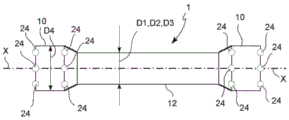
In said endoluminal prosthesis 1, a longitudinal direction X-X substantially parallel to or coinciding with the longitudinal development axis of the endoluminal prosthesis 1, a radial direction R-R orthogonal to the longitudinal direction X-X, and a circumferential or tangential direction orthogonal to both the longitudinal direction X-X and the radial direction R-R are defined. An outer radial direction RE is also defined, which is directed in a radial direction away from the longitudinal deployment axis of the endoluminal prosthesis 1 and an inner radial direction opposite to the outer radial direction RE.
The endoluminal prosthesis 1 is a multi-layer endoluminal prosthesis comprising two or more layers 5, 6, 7.
According to a preferred embodiment, the two or more layers are exactly three layers 5, 6, 7.
According to a preferred embodiment, the endoluminal prosthesis 1 comprises three armour (armor)9 forming three layers 5, 6, 7.
According to one embodiment, these layers, for example but not necessarily, the three layers that make the endoprosthesis or the device, are separated from each other, for example in the portion thereof facing the pathological area, for example in a resting or nominal state, which has a space or predetermined distance between them, i.e. between each layer, for example variable between 0.1mm and 3mm, to allow its continuous oscillation and reciprocal sliding, as occurs in the tunica media of normal subjects. The space is a space that is uninterrupted at least along the entire working portion 12 of the endoprosthesis. According to one embodiment, the distance between the layers is defined in such a way that endothelial cells never adhere between the layers, preventing them from forming a bridge between the layers, preventing their compression, thus avoiding flow obstructions in the side branch vessels branching from the aorta, always ensuring the patency of these side branch vessels.
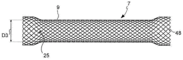
According to a preferred embodiment, the two or more layers comprise a first layer 5 having a predetermined nominal caliber D1 of the first layer, a second layer 6 having a predetermined nominal caliber D2 of the second layer smaller than the nominal caliber D1 of the first layer, and a third layer 7 having a predetermined nominal caliber D3 of the third layer smaller than both the nominal caliber D1 of the first layer and the nominal caliber D2 of the second layer. According to one embodiment, the two or more layers are coaxial.
At least one layer 5 or 6 or 7 of the two or more layers 5, 6, 7 comprises at least one thread- like element 8, 38, 48 forming a armour 9. According to one embodiment, each layer 5 or 6 or 7 of the two or more layers 5, 6, 7 comprises at least one thread-like element 8.
According to one embodiment, the first layer 5 comprises first thread elements 8, the second layer 6 comprises second thread elements 38, and the third layer comprises third thread elements 48.
According to a preferred embodiment, at least one layer 5 or 6 or 7 of the two or more layers 5, 6, 7 comprises a single thread- like element 8, 38, 48 forming the armour 9. In this way, a layer can be manufactured with a single thread- like element 8, 38, 48. According to one embodiment, each layer 5 or 6 or 7 of the two or more layers 5, 6, 7 comprises a single thread- like element 8, 38, 48.
According to a preferred embodiment, the armour 9 is interwoven armour forming a mesh.
According to one embodiment, at least one thread- like element 8, 38, 48 is deployed in the armour 9 in a substantially helical manner.
According to one embodiment, the armour 9 is an interwoven armour forming a fabric, according to one embodiment a fabric of the weft and warp type, or of the open mesh type, wherein the two opposite ends 28, 29 of at least one thread- like element 8, 38, 48 are alternately crossed at a crossing point 30. According to one embodiment, some of the intersections 30 have a first thread element end 28 arranged radially outwardly with respect to a second thread element end 29, and some of the intersections 30 have a second thread element end 29 arranged radially outwardly with respect to the first thread element end 28.
According to one embodiment, the first thread element end 28 and the second thread element end 29 form a crossing angle α with respect to the longitudinal axis of the endoluminal prosthesis 1. According to one embodiment, the crossing angle α is between 30 ° and 60 °. According to one embodiment, the crossing angle α is between 40 ° and 50 °, and according to one embodiment, the crossing angle α is substantially equal to 45 °. By providing the intersection angle α, the arrangement of endothelial cells of the wall of a natural vessel (e.g., a portion of a natural aorta) can be simulated. In fact, as is known, the endothelial cells of the native vessel wall are aligned with the mean blood flow direction during the systolic phase, and the blood flow during the systolic phase may proceed substantially helically or spirally.
According to one embodiment, the two opposite ends 28, 29 of the single thread- like element 8, 38, 48 are connected to each other by end connection means 25. According to one embodiment, the end connection means 25 is adapted to form a rigid connection between the two opposite ends 28, 29.
The endoluminal prosthesis 1 comprises at least one anchoring portion 10 suitable for anchoring to an anatomical portion 11 of the wall of the cavity 4 of the anatomical structure 3. The anchoring portion 10 is adapted to form a substrate that facilitates adhesion of newly formed vascular endothelial tissue, similar to a stent.
The endoluminal prosthesis 1 comprises at least one working portion 12 suitable to face a pathological portion 13 of the anatomical structure 3. For example, the pathological portion 13 is an aneurysm sac.
Thanks to the provision of at least one anchoring portion 10 and at least one working portion 12, the endoluminal prosthesis 1 can be anchored to a substantially healthy part of the anatomy 13. Thanks to the provision of at least one anchoring portion 10 and at least one working portion 12, the endoluminal prosthesis 1 extends the working portion 12 along the pathological section to reform the caliber equal to the healthy diameter of the vessel in which the endoprosthesis is implanted.
According to one embodiment, the anchor portion 10 is longitudinally separated from the working portion 12. In other words, moving in the longitudinal direction along the endoprosthesis, the anchoring portion 10 is encountered first, and then the working portion 12 is encountered.
Advantageously, according to one embodiment, at least in the working portion 12 of the endoluminal prosthesis 1, the two or more layers 5, 6, 7 are separated from each other. This prevents having to provide a connecting element between one layer 5 or 6 or 7 and an adjacent layer in the working portion 12.
According to one embodiment, working portion 12 has a diameter or caliber D1 in the absence of radial stress that is similar or equal to the healthy diameter D1 of the corresponding anatomical portion in which it is to be implanted. For example, the endoprosthesis has a working portion whose radial diameter or caliber D1 is equal to the internal average diameter D1 of a healthy portion of the aorta in which the endoprosthesis must be implanted when an aneurysm is formed in this portion of the aorta.
The provision of such an endoluminal prosthesis 1 allows the manufacture of two or more layers 5, 6, 7, which are substantially independent of each other in the working portion 12. According to one embodiment, in at least one anchoring portion 10, two or more layers 5, 6, 7 are adjacent to each other and constrained to each other on at least one other layer.
As a result of the provision of two or more layers 5, 6, 7 separated from each other in the working portion 12, a space may be provided between adjacent layers 16, which space is adapted to allow a fluid (e.g. blood) to flow between the two adjacent layers 5, 6, 7 at least in a substantially longitudinal direction X-X. According to one embodiment, the space between adjacent layers 16 is substantially annular cylindrical to surround the boundary defined by the two adjacent layers.
Since two or more layers 5, 6, 7 are provided in the working portion 12, which are separate from each other, relative movement between the two or more layers 5, 6, 7 is allowed even after implantation of the endoluminal prosthesis 1. In this way, adhesion and growth of vascular endothelial cells is prevented at least on the layer or layers 6, 7 having the smaller caliber D2, D3, and according to one embodiment on all the layers 5, 6, 7 of the working portion 12 of the endoluminal prosthesis 1. For example, two or more layers 5, 6, 7 separated from each other in the working portion 12 may be longitudinally and circumferentially as well as radially movable relative to each other. This gives the endoluminal prosthesis 1 improved flexibility, including torsional flexibility. This allows an extended service life compared to known solutions.
Due to the provision of two or more layers 5, 6, 7 separated from each other in the working portion 12, an endoluminal prosthesis 1 with improved flexibility is provided, which is suitable for implantation in curved anatomical structures 3, such as the aortic isthmus 22.
According to one embodiment, such an endoluminal prosthesis 1 is suitable for embodiments having an increased longitudinal extension compared to known solutions.
According to one embodiment, at least one wire-like element 8 is made of a superelastic material. According to one embodiment, at least one thread-like element 8 is made of a material suitable to retain the memory of a predetermined shape and to regain this predetermined shape when it is subjected to thermal variations and/or mechanical stresses. According to one embodiment, the at least one thread-like element 8 is at least partially made of nitinol. According to one embodiment, the at least one threadlike element 8 is at least partially made of nitinol adapted to regain a predetermined shape when heated and/or mechanically stressed. According to one embodiment, the at least one thread-like element 8 comprises a coating suitable for modulating the biological interaction between the endoluminal prosthesis 1 and the wall of the implant anatomy 3.
According to a preferred embodiment, the at least one thread- like element 8, 38, 48 of the armour 9 of each layer 5, 6, 7 defines a plurality of windows 15, the plurality of windows 15 being adapted to put the prosthetic lumen 2 in fluid communication with a pathological portion 13 of the anatomical structure 3 (for example an aneurysmal sac).
According to one embodiment, the armour 9 formed by at least one thread- like element 8, 38, 48 of one layer is circumferentially or angularly offset with respect to the armour of one or more adjacent layers by a predetermined amount which is less than the circumferential distance between two successive intersections 30, and according to one embodiment by less than one third of the circumferential distance between two successive intersections 30. In this way, the plurality of windows 15 of one layer are substantially offset from the plurality of windows 15 of one or more adjacent layers, but at the same time, the windows 15 of adjacent layers are substantially aligned, so that the endoluminal prosthesis 1 is suitable for placing the prosthesis lumen 2 in fluid communication with the pathological portion 13 of the anatomical structure 3. According to one embodiment, the alignment between the windows 15 of adjacent layers is chosen in such a way as to filter elements of larger dimensions, such as thrombi, to prevent their migration by convection or diffusion from the prosthesis lumen towards the pathological part 13 (for example the aneurysm sac).
According to one embodiment, the space between adjacent layers 16 is in fluid communication with the prosthesis lumen 2 through a plurality of windows 15 of the layers 6, 7, the plurality of windows 15 being radially inward with respect to the space between adjacent layers 16. In this way, a flow of fluid (for example blood) is allowed to flow from the prosthesis lumen 2 to the pathological portion 13 (for example aneurysmal sac) and vice versa from the pathological portion 13 (for example aneurysmal sac) to the prosthesis lumen 2.
Since two or more layers 5, 6, 7 are provided in the working portion 12, separated from each other, the behaviour of the mesomembranous structure of a native blood vessel can be mimicked or reproduced.
Thanks to the provision of such an endoluminal prosthesis 1, it is possible to create a flow diversion that strongly reduces the disturbances of the blood flow inside the aneurysm pocket, allowing the pressure on the walls of the aneurysm pocket to be reduced, thus preventing the rupture of the walls of the aneurysm pocket and thus facilitating the resorption of the aneurysm. The provision of a plurality of windows 15 allows the blood flow into the aneurysm sac to be substantially laminar, while allowing the patency of the aneurysm sac and, in the presence of the aneurysm sac, the distally branched side branch vessels 23 to be maintained. In this way, the biological tissue facing the aneurysm sac can be supplied, albeit in a weakened manner.
According to one embodiment, at least one anchoring portion 10 comprises at least one layer connecting means 24 between two or more layers 5, 6, 7. According to one embodiment, the layer connecting means 24 between two or more layers 5, 6, 7 form a rigid connection and are therefore not adapted to allow relative movement between adjacent layers in the anchoring portion 10. According to one embodiment, the layer connection means 24 and the end connection means 25 are identical connection elements 24, 25, for example metal elements, such as sleeves for pressure or crimp connections. According to one embodiment, at least one of the layer connection means 24 and the end connection means 25 is made of a radiopaque material, so that the endoluminal prosthesis 1 can be detected by a biological imaging acquisition device (for example a radiological device) after implantation in the anatomical structure 3.
According to one embodiment, at least one anchoring portion 10 of the endoluminal prosthesis comprises at least two (according to one embodiment at least three) connecting elements 24, 25, equally spaced in the circumferential direction and placed substantially at the same height along the longitudinal direction X-X.
According to a preferred embodiment, the endoluminal prosthesis comprises at least two anchoring portions 10 longitudinally opposite with respect to at least one working portion 12. According to one embodiment, at least two opposite anchoring portions 10 are located at opposite ends 26, 27 of the endoluminal prosthesis 1. The opposite ends 26, 27 include a proximal end 26 and a distal end 27. According to a preferred embodiment, at least one anchoring portion 10 has a smaller longitudinal extension with respect to the working portion 12.
According to a preferred embodiment, at least one anchoring portion 10 has a greater caliber with respect to at least one working portion 12. According to a preferred embodiment, all the layers 5, 6, 7 of at least one anchoring portion 10 have a greater caliber with respect to at least one working portion 12.
The provision of the anchoring portion 10 allows a radial thrust to act on the wall of the anatomical portion 11, which keeps the endoluminal prosthesis 1 in position in the anatomical structure 3 in which it is implanted. According to one embodiment, the dimensions and material of the at least one anchoring portion 10 are adapted to exert a radial preload on the wall of the anatomical portion 11.
According to a preferred embodiment, the endoluminal prosthesis 1 has a substantially dog-bone shape, comprising opposite ends 26, 27, which are larger than the portion of the endoluminal prosthesis 1 longitudinally between the two opposite ends 26, 27.
According to one embodiment, the working portion 12 has a substantially truncated conical shape. In this way, the endoluminal prosthesis 1 is adapted to mimic the shape of the wall of a blood vessel (e.g. an artery), the caliber of which decreases distally. According to one embodiment, distal end 27 has a smaller caliber than proximal end 26.
According to one embodiment, the anchoring portion 10 has a substantially truncated-cone shape with a taper increasing towards the end of the endoprosthesis 1.
According to one embodiment, at least one thread- like element 8, 38, 48 is a thread.
According to one embodiment, at least one thread- like element 8, 38, 48 is substantially in the form of a band or strip having a transverse dimension substantially greater than its thickness.
According to one embodiment, the endoluminal prosthesis 1 is a stent-no-graft. In other words, it is an intraluminal prosthesis without textile fibers.
According to one embodiment variant, at least one of the two or more layers 5, 6, 7 comprises a graft fabric to form at least a part of the endoluminal prosthesis 1. According to one embodiment, the graft fabric is associated with the armor layer 9 of the layer. According to one embodiment, the graft fabric is associated with the anchoring portion 10 by means of at least one connecting element 24, 25.
According to one embodiment, the endoluminal prosthesis 1 comprises a bifurcation of the prosthesis lumen 2, suitable for implantation in an anatomical structure 3 comprising a pathological section 13, the pathological section 13 being provided with a bifurcation, for example of the iliac arteries, distal to the descending section of the aorta.
According to a preferred embodiment, the intraluminal prosthesis is self-expanding. The endoluminal prosthesis 1 is adapted to be delivered and released to a predetermined implantation site within the anatomical structure 3 by a release means 31, e.g. a catheter, the endoluminal prosthesis 1 being mounted in a radially contracted configuration on the release means 31. For example, the release device 31 comprises a guide element 41 and a loading sleeve 46 suitable for receiving the endoluminal prosthesis 1 and the armour 9 of at least one layer of the endoluminal prosthesis 1.
A method of manufacturing a multilayer endoluminal prosthesis according to any of the preceding embodiments will be described.
A method of manufacturing a multilayer endoluminal prosthesis 1 comprises at least the following steps.
A. A table comprising at least one spindle 14 is arranged.
B. At least one first thread element 8 is repeatedly wound around at least one mandrel 14 to form a armour 9 of the first layer 5.
C. The armour 9 of the first layer 5 is separated from the at least one mandrel 14. This step may be performed, for example, by elastically deforming the armour 9.
D. At least one second linear element 38 is repeatedly wound around at least one mandrel 14 to form the armour 9 of the second layer 6. According to one embodiment, the mandrel (spindle)14 used to interlace the armour 9 of the second layer 6 has a smaller gauge than the mandrel used to form the armour 9 of the first layer 5, although it may be, for example, the same mandrel 14 with gauge adaptation capability, for example by removing the over-mandrel.
E. The armour 9 of the second layer 6 is separated from the at least one mandrel 14. This step may be performed by elastically deforming the armour 9.
F. The armour 9 of the first layer 5 is fitted over the armour of the second layer 6.
According to one possible mode of operation, before step C, a heat treatment may be provided to cause the armour 9 of the first layer 5 to acquire a memory of its shape on the mandrel.
According to one possible mode of operation, before step E, a heat treatment may be provided to ensure that the armour 9 of the second layer 6 acquires its memory of shape on the mandrel.
According to one possible mode of operation, the method provides for repeating steps B to F for the third layer 7.
According to one possible operating mode, step F comprises at least one but also all of the following sub-steps.
G. By means of the release means 31 or the unfolding means, the armour 9 of the first layer 5 is adhered in a support means 32 having a support wall adapted to at least partially, but for example completely, adhere the armour 9 of the first layer 5. According to one embodiment, the support means 32 is an openable support means comprising a reversible closing means 45. For example, the support means 32 is a sleeve delimiting a device cavity advantageously shaped to replicate the shape of the armour of the layers 5, 6, 7, in order to facilitate the removal of the armour of two or more layers 5, 6, 7 from the support means cavity. According to one embodiment, the support means 32 is substantially cup-shaped and comprises a bottom wall 36, the bottom wall 36 being provided with a centering hole 40, the centering hole 40 being adapted to receive a portion of the guiding element 41 of the release means 31 to provide certainty of the radial positioning of the release means 31 within the support means 32. According to one embodiment, the guide element 41 comprises a stop portion 37, the stop portion 37 having a larger caliber than the central hole 40 to provide certainty of the longitudinal positioning of the release device 31 within the support device 32. According to a further step, the armour 9 of the first layer 5 is released in the support means 32.
H. The armour 9 of the second layer 6 is conveyed by the releasing means 31 in the supporting means 32, in which supporting means 32 the armour 9 of the first layer 5 has been received.
According to a further step, the armour 9 of the second layer 6 is released in the support means 32 in which the armour of the first layer 5 is already present.
I. The relative position of the thread- like elements 8, 38 of the armour 9 of the first and second layers 5, 6 is adjusted, for example by adjustment means 33 (e.g. optical), before releasing the layers into the support means 32. For example, the adjustment means 33 comprise a dial element 34 provided on the support means 32, the dial element 34 cooperating with an indicator 35 provided on the release means 31. For example, step I allows the armour 9 of two adjacent layers 5, 6, 7 to be angularly or circumferentially offset by a predetermined angular amount.
J. At least one section of at least one threadlike element 8 of the armour 9 of the first layer 5 (for example in the connection between at least one working portion 12 and at least one anchoring portion 10) is connected (according to one embodiment but not necessarily crimped together) with at least one threadlike element 8 of the armour 9 of the second layer 6 to form at least one anchoring portion 10. According to one embodiment, but not necessarily, this step is performed by using a crimping tool 39.
According to one possible operating mode, step J is carried out by opening the support means 32 and removing at least two layers associated with each other. According to one embodiment, the removal of the at least two interrelated layers is performed after assembling and temporarily fixing the at least two layers on an expandable element 38 (e.g., a balloon for a stent) associated with the release device 31.
According to one embodiment, step B is carried out by using at least one return and winding device 42, which device 42 is movable with respect to the mandrel 14 and is associated with at least one thread- like element 8, 38, 48. For example, the return and winding device 42 is a shuttle adapted to move at least longitudinally and circumferentially with respect to the mandrel 14. According to one embodiment, the return and winding device 42 comprises at least two separate shuttles that are movable independently of each other and are movable at least longitudinally and circumferentially with respect to the mandrel 14. According to one embodiment, the spindle 14 is a movable element, for example adapted to rotate about its longitudinal axis. According to one embodiment, the return and winding device 42 is integrally associated with a support structure 46 movable with respect to the mandrel 14.
According to one embodiment, step B is performed by winding the two opposite ends 28, 29 of a single thread- like element 8, 38, 48 to form the interwoven armour 9.
According to one embodiment, step B is performed by winding the two opposite ends 28, 29 of the single thread- like element 8, 38, 48 in circumferentially opposite directions, so as to form an interwoven armour 9, the interwoven armour 9 forming a weft-warp type fabric.
According to one embodiment, the mandrel 14 comprises a mandrel rod 43, for example in the shape of a dog bone, from which mandrel rod 43 the return fingers 44 are cantilevered, suitable to act as return elements for the at least one thread- like element 8, 38, 48 at least during step B and/or step D.
By this method, it is possible to assemble two or more layers to each other in a predictable and precise manner, and it is possible to realize an endoluminal prosthesis 1 having two or more coaxial layers.
Numerous modifications and substitutions may be made by those skilled in the art to adapt a particular situation to the teachings of the present invention without departing from the scope thereof.
According to one embodiment, the endoluminal prosthesis 1 at least partially defines a prosthesis lumen 2. This endoprosthesis is suitable for being implanted in an anatomical structure 3, which anatomical structure 3 at least partially defines at least one cavity 4 and comprises at least one treatment portion 13.
According to one embodiment, the endoluminal prosthesis 1 comprises at least three layers 5, 6, 7, which are coaxially arranged and have, in the undeformed state, a main extension along a longitudinal direction X-X and define a radial direction R-R orthogonal to the longitudinal direction X-X and an annular or substantially circumferential direction C-C orthogonal to the longitudinal direction X-X and to the radial direction R-R.
According to one embodiment, each layer 5 or 6 or 7 substantially completely overlaps the adjacent layer 5, 6, 7 in the undeformed state.
According to one embodiment, each of the three layers 5, 6, 7, 5 or 6 or 7 comprises at least one thread-like element 8 forming an interwoven armour 9 limited to at least one layer 5 or 6 or 7.
According to one embodiment, 38 the endoluminal prosthesis 1 comprises at least one working portion 12 adapted to face at least the treatment portion 13 of the anatomical structure 3.
According to one embodiment, the endoluminal prosthesis 1 comprises at least one anchoring portion 10 suitable for anchoring to an anatomical portion 11 of the wall of the cavity 4 of the anatomical structure.
According to one embodiment, the at least three layers 5, 6, 7 are geometrically identical to each other.
According to one embodiment, the at least three layers 5, 6, 7 are separated from each other at least in the working portion 12 of the endoluminal prosthesis 1, avoiding the provision of connecting elements between one layer 5 or 6 or 7 and at least one adjacent layer.
According to one embodiment, at least one working portion 12 comprises only at least one thread-like element 8, this thread-like element 8 forming a armour 9 by its interlacing or staggering which remains only inside one and the same layer 5 or 6 or 7, avoiding the connection of adjacent layers.
According to one embodiment, when the endoprosthesis is in an undeformed state, the working portion 12 of each layer 5 or 6 or 7 is structurally and geometrically separated from the adjacent layer 5 or 6 or 7, in addition to its possible support of the adjacent layer 5 or 6 or 7 in the radial direction R-R, so as to be free to move with respect to the adjacent layer 5 or 6 or 7.
According to one embodiment, the at least one thread- like element 8, 38, 48 of the armour 9 of each layer 5, 6, 7 defines a plurality of windows 15 adapted to put the prosthetic lumen 2 in fluid communication with the treatment portion 13 of the anatomical structure 3.
According to one embodiment, when in the undeformed state, at least one working portion 12 of each layer 5, 6, 7 has a plurality of windows 15, which are substantially identical to each other and to each other in all the layers 5, 6, 7.
According to one embodiment, when in the undeformed state, the extension or diameter D1, D2, D3 of the at least one working portion 12 of each layer 5, 6, 7 in the radial direction R-R or transverse to the longitudinal direction X-X is smaller than the extension or diameter D4 of the at least one anchoring portion 10 transverse to the longitudinal direction X-X.
According to one embodiment, the at least three layers 5, 6, 7 are mutually offset along the circumferential direction C-C around the longitudinal direction X-X when in an undeformed state.
According to one embodiment, at least one of the anchoring portions 10 of each layer 5, 6, 7 is connected to an adjacent anchoring portion 10 of an adjacent layer 5, 6, 7.
Thanks to the above described embodiments, blood flow regularisation is induced in the region of the aneurysm, resulting in a reduction of the stress on the aneurysm wall immediately after implantation and in a remodelling of the aneurysm wall itself in the medium and long term.
According to one embodiment, at least one working portion 12 of each layer 5, 6, 7 has a plurality of windows 15. The plurality of windows 15 are of the same shape and size in each of the layers 5, 6, 7 when the endoprosthesis is in an undeformed state.
According to one embodiment, the transverse dimensions of the at least three layers 5, 6, 7 in the radial direction R-R are also the same, D1-D2-D3, when in the undeformed state, so as to substantially abut against each other when one layer is fitted into another layer and avoid the effect of being directed substantially radially R-R, if not supported, and so as to be substantially free to move relative to each other at least in the longitudinal direction X-X and the circumferential direction C-C.
According to one embodiment, at least one of the at least three layers 5, 6, 7 has a cross-section of the non-circular shape 47 transverse to its longitudinal direction X-X when in an undeformed state.
According to one embodiment, at least one of the at least three layers 5, 6, 7 has, when in the undeformed state, an oval or lens shape, or a trilobal shape 49, or a quadralobal shape, with a section transverse to its longitudinal direction X-X, so as to keep a portion of its circumferential C-C extension separated and detached from at least one adjacent layer 5, 6, 7.
According to one embodiment, at least one of the at least three layers 5, 6, 7 has, when in the undeformed state, a non-circular section transverse to its longitudinal direction X-X, the cross section of which changes its angular orientation or phasing along the longitudinal extension X-X of the layer, precisely defining the gap present between each layer along its entire longitudinal extension X-X or at least along the longitudinal extension X-X of its working portion 12.
According to one embodiment, at least one of the at least three layers 5, 6, 7 has, when in the undeformed state, a cross section transverse to its longitudinal direction X-X with a variable dimension along the longitudinal extension X-X of the layer 5, 6, 7.
According to one embodiment, when in the undeformed state, the at least three layers 5, 6, 7 are angularly aligned along the circumferential direction C-C, so as to align the plurality of windows 15 adapted to put the prosthesis lumen in fluid communication 2 with the treatment portion 13 of the anatomical structure 3, so that in the deformed state of the endoprosthesis implanted in the vessel to be treated, the windows are offset between each layer, ensuring the desired porosity of the endoprosthesis.
According to one embodiment, the thread-like element 8 has a circular cross-section transverse to its longitudinal extension 50.
According to one embodiment, the thread-like element 8 has an elliptical cross-section transverse to its longitudinal extension 51; or an elliptical cross-section 51 with the diagonal of the ellipse pointing substantially in the circumferential direction C-C of the endoprosthesis; or a square cross-section 52; or a rectangular cross-section 53; or a rectangular cross section 53 with the long side of the rectangle pointing substantially in the circumferential direction C-C of the endoprosthesis; or a polygonal cross-section 54, such as hexagonal.
According to one embodiment, the thread-like element 8 has a multi-layer body, wherein each layer is made of a different material.
According to one embodiment, the thread-
like element 8 has a multilayer body, wherein the innermost layer or core is made of a
metallic material 55, for example made of a superelastic material, for example made of
Made of a different material, and the
outermost layer 56 is made of a bioabsorbable or bioerodible material, for example.
According to one embodiment, at least a portion of the thread-
like element 8 comprises
According to one embodiment, at least a portion of the threadlike element 8 comprises a chromium-cobalt alloy.
According to one embodiment, at least a portion of the thread-like element 8 comprises MP 35N.
According to one embodiment, at least a portion of the thread-
like element 8 comprises
According to one embodiment, at least a portion of the thread-like element 8 comprises a polymer material.
According to one embodiment, at least a portion of the thread-like element 8 comprises a bioerodible (bioerodible) polymer material.
According to one embodiment, at least a portion of the thread-like element 8 comprises a bioerodible polymeric material loaded with a drug, such as one or more drugs dispersed in a polymeric matrix.
According to one embodiment, the armour 9 interwoven by the thread-like elements 8 has a weft and warp interweaving pattern formed by threads and by simply interweaving, each thread 8 passing along the thread-like element 8 above and then below the thread through which the thread-like element 8 passes.
According to one embodiment, the armour 9 interwoven by the thread-like elements 8 has a weft and warp interweaving pattern formed by a single thread and by simple interweaving, each thread 8 passing along the thread-like element 8 above and then below the thread through which the thread-like element 8 passes.
According to one embodiment, the armour 9 interwoven by the thread-like elements 8 has a weft and warp interweaving pattern formed by the threads and by the interweaving, each thread 8 passing twice over and then twice under the thread passing along the thread 8.
According to one embodiment, the armour 9 interwoven by the thread-like elements 8 has a weft and warp interweaving pattern obtained by interweaving a first thread 8 with a second thread 57, the second thread 57 having a larger cross-section than the first thread.
According to one embodiment, the armour 9 interwoven by the thread-like elements 8 has a weft and warp interweaving pattern obtained by interweaving a first thread 8 with a second thread 57, wherein at least a portion of the second thread 57 comprises a bioerodible material.
According to one embodiment, the armour 9 interwoven by the thread-like elements 8 has a weft and warp interweaving pattern obtained by the first threads 8 interweaving at a constant thread stretch interweaving angle when the endoprosthesis is in an undeformed state.
According to one embodiment, the armour 9 interwoven by the thread-like elements 8 has a weft and warp interweaving pattern obtained by at least one thread 8, the thread 8 being interwoven with a constant thread stretch interweaving angle of 45 ° with respect to the circumferential direction C-C, when the endoprosthesis is in an undeformed state.
According to one embodiment, the armour 9 interwoven by the thread-like elements 8 has a weft and warp interweaving pattern obtained by at least one thread 8, the thread 8 being interwoven with a constant thread stretch interweaving angle of less than 45 ° with respect to the circumferential direction C-C, when the endoprosthesis is in an undeformed state.
According to one embodiment, the armour 9 interwoven by the thread-like elements 8 has a weft and warp interweaving pattern obtained by at least one thread 8, the thread 8 being interwoven with a constant thread stretch interweaving angle greater than 45 ° with respect to the circumferential direction C-C, when the endoprosthesis is in an undeformed state.
According to one embodiment, the armour 9 interwoven by the thread-like elements 8 has, in the undeformed state of the endoprosthesis, an interwoven pattern of weft and warp yarns obtained by at least one interwoven thread 8, forming a plurality of windows 15 having a predetermined width of 3mm in a direction parallel to the longitudinal direction X-X.
According to one embodiment, the endoprostheses of at least three layers 5, 6, 7 each comprise a armour 9 interwoven by thread elements 8, having a weft and warp interweaving pattern obtained by at least one interwoven thread 8, the endoprostheses forming a plurality of windows 15, the plurality of windows 15 forming, when the three layers are overlapped and in an undeformed state, overlapping windows having a total endoprosthesis free width of 1mm in a direction parallel to the longitudinal direction X-X.
According to one embodiment, the endoprostheses of the layers 5, 6, 7 each comprise a armour 9 interwoven by thread elements 8, the thread elements 8 having an interwoven pattern of weft and warp yarns obtained by at least one interwoven thread 8, forming a plurality of windows 15, the plurality of windows 15, when the layers are stacked and in an undeformed state, forming superimposed windows having a total free width of the endoprosthesis in a direction parallel to the predetermined longitudinal direction X-X; wherein, in a single layer 5, 6, 7, the number of windows 15 of a single layer is given by the following relation:
ncl ═ pi φ/Nl × Dc and
Sl=360/Ncl×Nl
wherein
Ncl: number of windows 15 of a single layer 5, 6, 7
Phi: diameter of the working portion 12 of the endoprosthesis
Nl: number of layers 5, 6, 7 forming the endoprosthesis
Dc: diagonal of window generated by overlapping superposition of layers and angular offset
Sl: the angular offset between the layers in the endoprosthesis.
According to one embodiment, the armour 9 interwoven by the thread-like elements 8 has a weft and warp interweaving pattern obtained by at least one interwoven thread 8, in at least some interweaving the interweaving being obtained by pulling or tensioning the thread 8 during weaving.
According to one embodiment, at least one of the layers 5, 6, 7 comprises a first telescopic layer portion 59, which is received in a second telescopic layer portion 60, the two portions being mutually movable in the longitudinal direction X-X.
According to one embodiment, the wire used to make the layers is characterized by having a circular cross-section. Various types of cross-sections other than circular cross-sections may be configured to provide specific features to the layer or some of them, such as: greater radial or axial stiffness; greater coverage of the vessel surface or interface with the aneurysm; specific fluid dynamic effects.
According to one embodiment, the characteristic feature of the thread is its material of manufacture. A preferred solution provides
The use of wires. The following may be considered as alternative materials: other high elastic metal alloys (CoCr alloy, MP35N,
Etc.), a polymer, a bioerodible polymer, or a bioerodible polymer loaded with a drug.
The layers may be made of wires of different materials to obtain specific functional properties. In particular, the introduction of a bioerodible polymer wire to make one or more layers, or portions of such layers, allows for a component having a variable porosity that varies over time. From this point of view, a particularly interesting shape for manufacturing wires is to provide a metal core coated, for example, with a bioerodible polymer.
According to one embodiment, the use of a drug dispersed in a polymer matrix will allow for the implementation of diverse and customized therapeutic solutions.
According to one embodiment, the interlacing of the threads in the preferred embodiment is characterized by a simple weft-warp interlacing pattern obtained with a single thread, and by a 45 ° crossing with respect to the longitudinal axis of the endoprosthesis. In a broad sense, the interlacing of the threads and their characteristics are the basic elements used to define the porosity and consistency of the device. The identified possible variation factors are:
a weaving scheme and/or
Diameter and shape of the interwoven wires and/or
Material of the braided wire and/or
-crossing angle of the interlaced lines and/or
Tensioning and/or drawing of interwoven threads
A mixture of two or more of the above factors.
According to one embodiment, the interlacing pattern employed in the formation of the layers may impart specific mechanical characteristics to the endoprosthesis having the same diameter and the same wire material, in particular with regard to compliance and the possibility of micro-movement of the wires when exposed to blood flow. These two features can be obtained in an isotropic or anisotropic manner, always on an interlaced pattern.
According to one embodiment, the use of wires of different diameters and/or shapes may result in a layer with a particular compliance and a particular porosity. These embodiments differ in that a single wire is chosen with the entire layer formed.
According to one embodiment, a solution is adopted in which variably alternating metal wires are interwoven with wires of bioerodible polymer to obtain a lower initial porosity, which is intended to increase with dissolution of the polymer network.
According to one embodiment, another design for altering the isotropic and/or anisotropic porosity and compliance is represented by the interlacing angle of the lines. A very large or very small winding angle relative to the longitudinal axis of the endoprosthesis will provide a lower porosity (other factors being equal). A smaller winding angle will provide a lower radial resistance, and vice versa for larger winding angles.
According to one embodiment, the tension applied to the thread at the time of weaving allows to obtain a layer of thread with more tension, characterized by a lower compliance and possibility of thread movement.
According to one embodiment, by mixing the above listed interleaving variants, a great design flexibility is given. Two examples of particular interest are given by solutions with variable angular interlacing for radially stiffer ends and more conformal working portions, or by creating a central region with low porosity in the aneurysm portion (possibly using biodegradable threads).
According to one embodiment, a preferred design of the endoprosthesis provides for the use of 3 equal layers, which are equally offset from one another in the circumferential angular direction.
According to one embodiment, the basic parameter of the device is a measurement of the diagonal Dc of a single window or cell of the endoprosthesis or stent, which is the result of the superposition of a plurality of equal layers. This diagonal Dc is important because it measures the porosity of the device. Which essentially represents the preferred porosity of the endoprosthesis.
According to one embodiment, the same value of the diagonal Dc may be obtained by superimposing many layers composed of a single window or large cell (cell), or several layers composed of a single small cell. The basic relationship for adjusting these geometries is as follows:
number of cells of a single layer:
Ncl=πφ/(Nl×Dc)
angular offset between layers in the entire device:
Sl=360/(Ncl×Nl)
wherein:
ncl: the number of cells of a single layer;
phi: the diameter of the working portion of the entire stent;
nl: the number of layers forming the entire stent;
dc: diagonal lines of cells resulting from the superposition and offset of layers;
sl: the angular offset between the layers in the overall device.
According to one embodiment, Dc is 1 mm; nl is 3; phi is 20 mm; then Ncl is 20 and Sl is 6 °.
The same Dc value can be obtained with 4 layers, but with Ncl-16 and Sl-5.6 °.
Achieving the same final porosity value Dc with many loose mesh layers instead of denser mesh layers may give the stent greater compliance and the potential for single wire movement, but increases the risk of non-uniformity in the bending area.
Another variation of the available designs on the layers is represented by the possibility of creating areas with more or fewer layers along the axis.
According to one embodiment, the use of different layers allows considerable manufacturing flexibility depending on the consistency of the mesh, the diameter and shape of the wire, the material of the wire, the winding angle of the wire. These variations allow many subtle differences in performance in terms of mechanical behavior and compliance.
From this point of view, the possibility of introducing a bioerodible polymer layer to give the scaffold a porosity that varies over time appears to be of particular interest.
According to one embodiment, the individual layers can be connected to each other as in the basic design by means of crimped bushings or by means of crimped bands, welds, ties, dedicated anchoring systems.
According to one embodiment, the number of connection points may vary: more "tie" layers result in a stiffer, resilient, less compliant scaffold with less wire mobility, but more accurate and uniform in porosity. The effect of the connection may be distributed appropriately according to the function to be realized.
Attractive implementation options based on the interconnect pattern between layers may be as follows. If the layers and, in the preferred design, are connected to each other only at the ends and are not oversized relative to each other, the layers in the working area will have a degree of relative circumferential freedom. This degree of freedom will cause local changes in the resulting porosity, especially in case of bending or in case of any coiled implantation conditions. In particular, again in the basic design of providing three offset layers to obtain at least a minimum initial final porosity, the changes caused by bending and bowing will result in an inevitably higher local porosity relative to the undeformed state (wider grid). This observation is reversed, i.e. the connection between the layers is maintained only at the ends, but due to the fully phased layers there will be an initial undeformed state with a large mesh. In a bent or rolled condition, the resulting relative movement between the layers will inevitably produce a smaller resulting mesh, i.e. lower porosity. Such a device can be used for devices intended for curved implants, from aneurysms to extrados, since the porosity of the area facing the aneurysm itself will be lower than the original porosity, thus enabling the desired fluidized effect of the fluidized bed to be enhanced.
In a preferred design, the three layers are "lightly in contact" with each other, i.e., they are in contact with each other without significant radial force exchange. By exploiting the difference in diameter between the layers, it is possible to give the stent a specific function overall: layers in exchange contact with significant radial forces will produce a stiffer, less compliant stent and less likely to have minor movement of the wires under the influence of blood flow; the non-contact layer is the opposite. Some variants that can be designed are shown here.
The layers may be separated from each other only by differences in diameter or by spacers.
A solution of particular interest, without the use of separators, is to provide one or more layers of polygonal shape, with stable and controlled distance of the separated layers. For example, in the three-layer version, the middle one has a blurry triangular shape. By using this triangulated dimension, different distances can be obtained between the outer and inner layers. Other polygonal shapes may also be used for this purpose.
The generatrices of contact between the layers may be rectilinear, i.e. parallel to the axis of the stent, or follow a particular shape, for example a spiral, to provide a particular trajectory for the blood flow within the layers.
The axial shape of the layers may also be varied to achieve specific functions, for example with a progressive curvature to avoid the "dog bone" effect at the ends after implantation, or with intermediate curved layers to create special fluidic effects.
This preferred design provides a stent that, although constructed of multiple layers, is monolithic in its entirety. It is possible to envisage a solution with two telescopic supports for the implant in order to achieve an optimal coverage of long lesions.
With the above solution, intraluminal prostheses allow a variety of clinical applications:
a) treatment of aneurysms in aortic extensions;
b) treatment of aneurysms in peripheral blood vessels;
c) treatment of aortic dissection.
REFERENCE LIST
1 intraluminal prosthesis
2 prosthetic lumen
3 anatomical Structure
4 anatomical cavity
5 first layer
6 second layer
7 third layer
8 the thread-like element, or the first thread-like element
9 armor
10 anchoring part of an endoprosthesis
11 anatomical part of an anatomical structure
12 working part of an endoprosthesis
13 pathological part of the anatomy
14 mandrel
15 window
16 spaces between adjacent layers
17 aneurysm
18 arch of aorta
19 descending aorta
20 thoracic aorta
21 abdominal aorta
22 aortic isthmus
23 collateral blood vessels
24-layer connection means, or connection elements
25 end connection means, or connection elements
26 proximal endoprosthesis end
27 distal endoprosthesis end
28 first thread-like element end
29 second linear element end
30 at the intersection
31 Release device
32 support device
33 adjusting device
34 scale element of an adjusting device
35 indicator for an adjustment device
36 bottom wall of the support device
37 stop portion
38 second linear element
39 crimping tool
40 centering holes
41 guide element of an adjusting device
42 return and take-up device
43 mandrel bar
44 mandrel fingers
45 reversible closing device
46 supporting structure
47 circular cross section at the longitudinal extension of the single layer
48 third thread-like element
49 trilobal cross-section at the longitudinal extension of the single layer
Circular cross section of 50 lines
Elliptical cross-section of line 51
Square cross-section of line 52
Rectangular cross section of 53 lines
Hexagonal cross section of line 54
55 wire metal core
56 outer layer of lines of bioerodible material
Second line 57 larger than the first line
58 second line of bioerodible material
59 first telescoping layer section
60 second telescoping layer section
61 Stent delivery System
62 first release sheath
63 second Release sheath
Number of windows of Ncl single layer
Diameter of the working part of phi endoprosthesis
Number of layers Nl forming the endoprosthesis
Dc diagonal of window resulting from overlapping superposition of layers and angular offset
Angular offset between layers in Sl endoprosthesis
D1 first layer caliber or nominal diameter
D2 second layer caliber or nominal diameter
D3 third layer caliber or nominal diameter
Caliber or nominal diameter of D4 anchoring portion
In the X-X longitudinal direction
R-R radial direction
C-C circumferential direction
RE outer radial direction