EP3427560A1 - Anhängevorrichtung - Google Patents
Anhängevorrichtung Download PDFInfo
- Publication number
- EP3427560A1 EP3427560A1 EP18182757.7A EP18182757A EP3427560A1 EP 3427560 A1 EP3427560 A1 EP 3427560A1 EP 18182757 A EP18182757 A EP 18182757A EP 3427560 A1 EP3427560 A1 EP 3427560A1
- Authority
- EP
- European Patent Office
- Prior art keywords
- coupling member
- towing device
- actuator
- hitch
- work vehicle
- Prior art date
- Legal status (The legal status is an assumption and is not a legal conclusion. Google has not performed a legal analysis and makes no representation as to the accuracy of the status listed.)
- Granted
Links
Images






Classifications
-
- B—PERFORMING OPERATIONS; TRANSPORTING
- B60—VEHICLES IN GENERAL
- B60D—VEHICLE CONNECTIONS
- B60D1/00—Traction couplings; Hitches; Draw-gear; Towing devices
- B60D1/24—Traction couplings; Hitches; Draw-gear; Towing devices characterised by arrangements for particular functions
- B60D1/42—Traction couplings; Hitches; Draw-gear; Towing devices characterised by arrangements for particular functions for being adjustable
-
- A—HUMAN NECESSITIES
- A01—AGRICULTURE; FORESTRY; ANIMAL HUSBANDRY; HUNTING; TRAPPING; FISHING
- A01B—SOIL WORKING IN AGRICULTURE OR FORESTRY; PARTS, DETAILS, OR ACCESSORIES OF AGRICULTURAL MACHINES OR IMPLEMENTS, IN GENERAL
- A01B59/00—Devices specially adapted for connection between animals or tractors and agricultural machines or implements
- A01B59/002—Details, component parts
- A01B59/004—Length-adjustable links
-
- A—HUMAN NECESSITIES
- A01—AGRICULTURE; FORESTRY; ANIMAL HUSBANDRY; HUNTING; TRAPPING; FISHING
- A01B—SOIL WORKING IN AGRICULTURE OR FORESTRY; PARTS, DETAILS, OR ACCESSORIES OF AGRICULTURAL MACHINES OR IMPLEMENTS, IN GENERAL
- A01B69/00—Steering of agricultural machines or implements; Guiding agricultural machines or implements on a desired track
- A01B69/003—Steering or guiding of machines or implements pushed or pulled by or mounted on agricultural vehicles such as tractors, e.g. by lateral shifting of the towing connection
- A01B69/006—Steering or guiding of machines or implements pushed or pulled by or mounted on agricultural vehicles such as tractors, e.g. by lateral shifting of the towing connection derived from the steering of the tractor
-
- B—PERFORMING OPERATIONS; TRANSPORTING
- B60—VEHICLES IN GENERAL
- B60D—VEHICLE CONNECTIONS
- B60D1/00—Traction couplings; Hitches; Draw-gear; Towing devices
- B60D1/01—Traction couplings or hitches characterised by their type
- B60D1/06—Ball-and-socket hitches
-
- B—PERFORMING OPERATIONS; TRANSPORTING
- B60—VEHICLES IN GENERAL
- B60D—VEHICLE CONNECTIONS
- B60D1/00—Traction couplings; Hitches; Draw-gear; Towing devices
- B60D1/24—Traction couplings; Hitches; Draw-gear; Towing devices characterised by arrangements for particular functions
- B60D1/246—Traction couplings; Hitches; Draw-gear; Towing devices characterised by arrangements for particular functions for actuating the hitch by powered means
-
- A—HUMAN NECESSITIES
- A01—AGRICULTURE; FORESTRY; ANIMAL HUSBANDRY; HUNTING; TRAPPING; FISHING
- A01B—SOIL WORKING IN AGRICULTURE OR FORESTRY; PARTS, DETAILS, OR ACCESSORIES OF AGRICULTURAL MACHINES OR IMPLEMENTS, IN GENERAL
- A01B59/00—Devices specially adapted for connection between animals or tractors and agricultural machines or implements
- A01B59/002—Details, component parts
- A01B59/008—Link connectors with spherical surfaces
-
- A—HUMAN NECESSITIES
- A01—AGRICULTURE; FORESTRY; ANIMAL HUSBANDRY; HUNTING; TRAPPING; FISHING
- A01B—SOIL WORKING IN AGRICULTURE OR FORESTRY; PARTS, DETAILS, OR ACCESSORIES OF AGRICULTURAL MACHINES OR IMPLEMENTS, IN GENERAL
- A01B59/00—Devices specially adapted for connection between animals or tractors and agricultural machines or implements
- A01B59/04—Devices specially adapted for connection between animals or tractors and agricultural machines or implements for machines pulled or pushed by a tractor
- A01B59/042—Devices specially adapted for connection between animals or tractors and agricultural machines or implements for machines pulled or pushed by a tractor having pulling means arranged on the rear part of the tractor
-
- B—PERFORMING OPERATIONS; TRANSPORTING
- B60—VEHICLES IN GENERAL
- B60D—VEHICLE CONNECTIONS
- B60D1/00—Traction couplings; Hitches; Draw-gear; Towing devices
- B60D1/24—Traction couplings; Hitches; Draw-gear; Towing devices characterised by arrangements for particular functions
- B60D1/42—Traction couplings; Hitches; Draw-gear; Towing devices characterised by arrangements for particular functions for being adjustable
- B60D1/44—Traction couplings; Hitches; Draw-gear; Towing devices characterised by arrangements for particular functions for being adjustable horizontally
-
- B—PERFORMING OPERATIONS; TRANSPORTING
- B60—VEHICLES IN GENERAL
- B60D—VEHICLE CONNECTIONS
- B60D1/00—Traction couplings; Hitches; Draw-gear; Towing devices
- B60D2001/001—Traction couplings; Hitches; Draw-gear; Towing devices specially adapted for use on vehicles other than cars
- B60D2001/008—Traction couplings; Hitches; Draw-gear; Towing devices specially adapted for use on vehicles other than cars specially adapted for implements, e.g. towed tools
Definitions
- the invention relates to a hitch for an agricultural work vehicle, comprising a coupling member.
- a ball-and-socket coupling in particular in a down-coupling design, is preferably used due to the increasing support loads.
- a propshaft needed, for example, to operate the attachment passes above the ball-and-socket coupling.
- the turning circle is usually not limited by the maximum tractor steering angle, but by the steering angle between the tractor and implement, as it is necessary to avoid contact between the implement drawbar and the Hubtechniksunterlenkern or the tractor rear wheels.
- wheel weights can be mounted on the rear wheels of a tractor.
- the assembly and disassembly of wheel weights is relatively expensive.
- wheel weights increase the mass moment of inertia of the wheels. This has a negative effect on the acceleration and braking behavior of the tractor.
- no stepless axle load adjustment during driving is possible.
- a hitch which is attached to the rear of an agricultural work vehicle.
- the hitch comprises two supported at the rear of the vehicle and vertically aligned side cheeks and a coupling member supporting plate.
- the plate can be fixed in a transport position or a working position.
- the DE 10 2013 211 516 A1 also describes a hitch for an agricultural work vehicle, comprising two supported on the rear vehicle and vertically oriented side cheeks and a plate carrying a coupling member.
- the plate is retractable in each case in horizontal guide grooves facing each other at lower ends of the side cheeks in a working position and can be locked by means of at least one adjusting bolt.
- the rear ends of the side cheeks are designed so that a smaller lateral width is formed in the region of the lower ends of the side cheeks.
- the invention has for its object to provide a hitch for an agricultural work vehicle that allows a small turning circle of the team.
- the hitch should contribute to a load optimization of agricultural work vehicle.
- the attachment process of an attachment should be facilitated by the hitch invention.
- the combination should have better driving and braking properties by the hitch invention.
- a stable driving behavior is to be achieved.
- the coupling member of the hitch is slidably mounted. It is connected to an actuator for displacement. It proves to be particularly advantageous to perform the coupling member longitudinally displaceable by means of a continuously operating actuator.
- longitudinal displacement means a displacement in or against the direction of travel.
- the displacement of the coupling member is largely horizontal. Under substantially horizontal is understood below an angle to the horizontal of less than 45 °, in particular less than 30 °, preferably less than 15 °.
- the actuator comprises at least one working cylinder, wherein in particular hydraulic cylinders and / or pneumatic cylinders are suitable.
- a double-acting cylinder is used, which operates either hydraulically or pneumatically.
- a double-acting hydraulic cylinder proves to be particularly favorable, since usually a sufficient hydraulic power source is available in the tractor and also a relatively simple implementation is possible because in a hydraulic system with a compact space high cylinder forces can be realized.
- an electric motor with threaded spindle are used as an actuator.
- the hitch device to a guide element.
- This guide element receives supporting loads, in particular supporting loads, which act in the vertical direction.
- the actuator is protected from damage due to excessive support loads.
- the guide element preferably has a rail and / or a groove. The guide element ensures a longitudinal displacement, wherein the displacement takes place largely in the horizontal direction with only a relatively small angle of inclination of less than 45 °, in particular less than 30 °, preferably less than 15 ° to the horizontal.
- the coupling member is in communication with a holding element.
- the retaining element may be, for example, a supporting plate.
- the coupling member is firmly connected to the holding element.
- the coupling member may be welded to the plate or fastened by a screw connection.
- the holding element is arranged displaceably in the guide element.
- the guide element may be side cheeks which have a groove in which the holding element embodied as a plate is displaceably arranged.
- the device has sensors which can detect data and then pass them on to a corresponding unit, which then determines depending on the data an optimal position of the coupling member and correspondingly controls the actuator, so that this by a longitudinal displacement brings the coupling member in an optimal position for each situation.
- the unit may be an evaluation device and / or control device and control device.
- a PID controller or a programmable logic controller (PLC) can be used.
- PLC programmable logic controller
- the inventive device a turning circle reduction of a team of work vehicle and attachment is possible.
- an axle load shift can be realized.
- the coupling member is preferably a ball-and-socket coupling. It proves to be particularly advantageous if the coupling is realized in a down-hitch design.
- the working vehicle is additionally equipped with a front ballast.
- the front ballast is movable, preferably longitudinally displaceable, is arranged.
- the inventive combination of a sliding hitch with a movable front load optimum stability of the work vehicle can be achieved for each application. It proves to be particularly favorable if the hitch and / or the front ballast are adjustable in their position to the working vehicle while driving. As a result, the driving stability can be optimized.
- FIG. 1 shows a working vehicle 1, which is provided with a towing device 2, which is arranged by means of an actuator 3 in the horizontal direction in the opposite direction or longitudinally displaceable.
- FIG. 1 shows the hitch 2 both in a first, with respect to the figure right position, close to the work vehicle 1 and in a second, with respect to the figure left position with a corresponding distance to the working vehicle.
- the actuator 3 is controlled via an arrangement 4.
- the supply pressure is called pv.
- the longitudinal displacement is shown in the figures with the symbol I DB .
- I DB Two positions of the hitch are shown. In this case, the first position has a shorter longitudinal displacement and the second position has a greater longitudinal displacement I DB .
- FIG. 2 shows a schematic representation of an actuator 3 and an arrangement 4 for controlling or regulating the actuator 3.
- the actuator 3 is a hydraulic cylinder in which a piston is slidably disposed.
- p LS denotes the load sensing pressure.
- the piston separates two spaces 5, 6 in the cylinder. To the room 5, a first line 7 and the space 6, a second line eighth
- the invention offers the advantage of a stepless axle load displacement.
- This stepless displacement proves to be particularly favorable compared to the use of wheel weights, since wheel weights are available only in fixed weight graduations of, for example, 50 kg, 100 kg, 250 kg.
- F DB tensile force
- the device When displayed in FIG. 2 the device is provided with two pressure sensors 9 and 10.
- the pressure sensor 9 detects the pressure in the conduit 7 or the space 5. This pressure is designated by p2.
- the sensor 10 detects the pressure in the line 8 or the space 6. The pressure is designated by p 1 .
- the tensile load can be determined. This is important for the driving strategy of the work vehicle.
- a determination of the tensile force F DB allows an implementation of a braking strategy of the team. For optimum braking of the tractor-trailer combination, a non-powered tractor-trailer connection is optimal, in which the tensile force F DB in the optimal case is zero. By determining the tensile force, this goal can be realized by a suitable braking strategy.
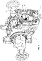
- FIG. 3 shows a support structure 11 of the working vehicle 1, which is designed in the embodiment as a rear axle housing, and the rear axle 12 of a tractor. Furthermore, a mounting block 13 is shown, in which a hitch 2 is integrated.
- FIG. 4 shows an enlarged view of the area in FIG. 3
- the coupling member 14 is designed as a ball head coupling.
- the coupling member 14 is arranged on a holding element 15, which is designed in the embodiment as a plate.
- the holding element 15 is arranged displaceably in a guide element 16.
- the guide element 16 is a shape of the attachment block 13, which has a groove for guiding the holding element 15.
- the groove of the guide element 16 is U-shaped and surrounds the plate-like holding element 15 on the laterally outwardly projecting end faces 17.
- the holding element 15 is arranged so as to be displaceable in the longitudinal direction, so that it is provided with an in FIG. 4 Actuator can be extended to the rear.
- FIG. 5 shows a perspective view of the attachment block 13 from below.
- the attachment block 13 comprises two side cheeks 18, which are vertically aligned and arranged parallel to one another.
- the attachment block 13 is connected via at least one attachment means 19 to a rear part of the work vehicle 1.
- the rear part is preferably a PTO housing or a differential housing of a tractor.
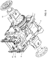
- FIG. 6 shows in a perspective view from below a support structure 11 of the agricultural work vehicle 1, which forms a rear axle housing of a tractor, and the laterally outwardly projecting tractor rear axle 12.
- the attachment block 13 is connected to the support structure 11.
- the attachment block 13 comprises the displaceably arranged towing device 2.
- FIG. 7 shows in a side view of the rear axle housing of a tractor with a mounting block 13 which includes the extendable hitch 2.
- the actuator 3 Via a fastening element 22, the actuator 3 is connected to the support structure 11.
- the actuator 3 is attached to the bottom of the rear axle housing.
- the actuator 3 has at the end of an extendable rod to a fastening element 23, with which the extendable hydraulic rod of the actuator 3 is connected to the holding element 15 of the hitch 2.
- the holding element 15 is as shown in FIG FIG. 7 as running longitudinally in the direction of travel extending rectangular plate. The longitudinal extent allows extension of the plate to the rear, so that the coupling member 14 can be brought into the desired position.
- the designed as an elongated plate holding member 15 is moved within a groove of the guide member 16.
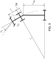
- FIGS. 8 and 9 show a turning circle reduction of a team of a work vehicle and an attachment.
- the maximum steering angle ⁇ E is limited by the lower links of a hoist.
- the geometrical proportions assumed below serve to illustrate the orders of magnitude and are based on commercially available tractors.
- ⁇ e arctan l U 1 l U 2 - l DB ⁇ 33 ° resulting in the following turning radius of the rear axle center of the tractor:
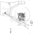
- FIG. 10 is shown how the device according to the invention the visibility when connecting or disconnecting the attachment to the work vehicle can be ensured.
- the executed as a ball coupling coupling member 14 is inserted horizontally in conventional hitches 2 according to the prior art at the lower end of a Buchmaulschiene 24. Therefore, it is not visible from the cab by the driver. If a pull jaw 25 is mounted, this considerably restricts the view of the ball head coupling. The field of view limitation increases with increasing height of the Buchmaulan eleven. If the pulling jaw 25 is fixed in the uppermost perforation of the Switzerlandmaulschiene 24, the coupling member 14 must be moved longitudinally to the height of the lower link, ⁇ ⁇ 0.6m, so that it is visible from the cabin. Preferably, this extension is done without full vertical load.
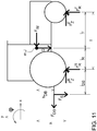
- FIG. 11 shows the operation of the device according to the invention for axle load displacement.
- About the invention can be linearly shifted in dependence on the vertical load F S on the variation of l DB the axle load.
- the wheel load increase at the rear axle leads to the corresponding relief of the front axle by the invention.
- a front ballast is attached in a particularly advantageous variant of the invention.
Landscapes
- Engineering & Computer Science (AREA)
- Life Sciences & Earth Sciences (AREA)
- Mechanical Engineering (AREA)
- Soil Sciences (AREA)
- Environmental Sciences (AREA)
- Transportation (AREA)
- Zoology (AREA)
- Agricultural Machines (AREA)
Abstract
Description
- Die Erfindung betrifft eine Anhängevorrichtung für ein landwirtschaftliches Arbeitsfahrzeug, umfassend ein Kupplungsglied.
- Es sind verschiedene Kupplungsvorrichtungen für landwirtschaftliche Arbeitsfahrzeuge bekannt mittels derer Anhänger, Anbaugeräte oder Arbeitsgeräte an das Zugfahrzeug, beispielsweise einen Traktor, ankoppelbar sind. In der Landwirtschaftstechnik werden immer häufiger schlagkräftigere Anbaugeräte eingesetzt, die einen entsprechend leistungsfähigen Traktor voraussetzen.
- Bei Anbaugeräten mit einem eigenen Fahrwerk wird aufgrund der steigenden Stützlasten vorzugsweise eine Kugelkopfkupplung insbesondere in einer Unten-Anhängungsausführung eingesetzt. Bei einer Unten-Anhängungsausführung verläuft eine Gelenkwelle, die beispielsweise für den Betrieb des Anbaugeräts benötigt wird, oberhalb der Kugelkopfkupplung.
- Große Gespanne haben den Nachteil, dass diese einen relativ großen Wendekreis aufweisen. Der Wendekreis wird meist nicht durch den maximalen Traktorlenkwinkel begrenzt, sondern durch den Einschlagwinkel zwischen Traktor und Anbaugerät, da es gilt, eine Berührung zwischen der Anbaugerätedeichsel und den Hubwerksunterlenkern bzw. den Traktorhinterrädern zu vermeiden.
- Zur Gewichts- und Achslastoptimierung können an den Hinterradfelgen eines Traktors Radgewichte montiert werden. Die Montage und Demontage von Radgewichten ist relativ aufwendig. Zudem erhöhen Radgewichte das Massenträgheitsmoment der Räder. Dies wirkt sich negativ auf das Beschleunigungs- und Bremsverhalten des Traktors aus. Weiterhin ist keine stufenlose Achslastanpassung während des Fahrbetriebs möglich.
- Bei herkömmlichen Anhängevorrichtungen nach dem Stand der Technik kann das Kupplungselement von der Kabine häufig nicht eingesehen werden. Dies erschwert den Anhängeprozess.
- In der
DE 10 2013 211 510 A1 wird eine Anhängevorrichtung beschrieben, die heckseitig an einem landwirtschaftlichen Arbeitsfahrzeug angebracht ist. Die Anhängevorrichtung umfasst zwei am Fahrzeugheck abgestützte und vertikal ausgerichtete Seitenwangen sowie eine ein Kupplungsglied tragende Platte. Die Platte kann in einer Transportposition oder einer Arbeitsposition befestigt werden. - Die
DE 10 2013 211 516 A1 beschreibt ebenfalls eine Anhängevorrichtung für ein landwirtschaftliches Arbeitsfahrzeug, umfassend zwei am Heckfahrzeug abgestützte und vertikal ausgerichtete Seitenwangen und eine, ein Kupplungsglied tragende Platte. Die Platte ist in jeweils in einander zugewandte horizontale Führungsnuten an unteren Enden der Seitenwangen in einer Arbeitsposition einziehbar und mittels zumindest eines Stellbolzens arretierbar. Die hinteren Enden der Seitenwangen sind so ausgeführt, dass eine geringere laterale Breite im Bereich der unteren Enden der Seitenwangen gebildet wird. - Der Erfindung liegt die Aufgabe zugrunde, eine Anhängevorrichtung für ein landwirtschaftliches Arbeitsfahrzeug anzugeben, das einen kleinen Wendekreis des Gespanns ermöglicht. Zudem soll die Anhängevorrichtung zu einer Lastoptimierung des landwirtschaftlichen Arbeitsfahrzeuges beitragen. Der Anhängeprozess eines Anbaugerätes soll durch die erfindungsgemäße Anhängevorrichtung erleichtert werden. Das Gespann soll durch die erfindungsgemäße Anhängevorrichtung bessere Fahr- und Bremseigenschaften aufweisen. Zudem soll ein stabiles Fahrverhalten erreicht werden.
- Diese Aufgabe wird erfindungsgemäß durch eine Anhängevorrichtung mit den Merkmalen des Anspruchs 1 gelöst, sowie durch ein Verfahren mit den Merkmalen des Anspruchs 10. Bevorzugte Varianten sind den Unteransprüchen, der Beschreibung und den Zeichnungen zu entnehmen.
- Erfindungsgemäß ist das Kupplungsglied der Anhängevorrichtung verschiebbar angeordnet. Zur Verschiebung steht es mit einem Aktor in Verbindung. Dabei erweist es sich als besonders günstig, das Kupplungsglied mittels eines stufenlos arbeitenden Aktors längsverschiebbar auszuführen. Im Folgenden wird unter längsverschiebbar eine Verschiebung in bzw. entgegen der Fahrtrichtung verstanden. Vorzugsweise erfolgt die Verschiebung des Kupplungsgliedes weitgehend horizontal. Unter weitgehend horizontal wird im Folgenden ein Winkel zur Horizontalen von weniger als 45°, insbesondere weniger als 30°, vorzugsweise weniger als 15° verstanden.
- Bei einer Variante der Erfindung umfasst der Aktor mindestens einen Arbeitszylinder, wobei sich insbesondere Hydraulikzylinder und/oder Pneumatikzylinder eignen. Bei einer besonders vorteilhaften Ausführung der Erfindung kommt ein doppelt wirkender Zylinder zum Einsatz, der entweder hydraulisch oder pneumatisch arbeitet. Ein doppelt wirkender hydraulischer Zylinder erweist sich als besonders günstig, da meistens eine ausreichende hydraulische Leistungsquelle beim Traktor zur Verfügung steht und zudem eine verhältnismäßig einfache Realisierung möglich ist, da bei einer Hydraulik mit einem kompakten Bauraum hohe Zylinderkräfte realisierbar sind.
- Ergänzend oder alternativ kann als Aktor beispielsweise auch ein Elektromotor mit Gewindespindel zum Einsatz kommen.
- Als besonders günstig erweist es sich, wenn die Aufnahme der Stützlast des Kupplungsgliedes über eine Längsführung realisiert wird und nicht ausschließlich vom Aktor selbst erfolgt. Bei einer besonders vorteilhaften Variante der Erfindung weist die Anhängevorrichtung dazu ein Führungselement auf. Dieses Führungselement nimmt Stützlasten auf, insbesondere Stützlasten, die in vertikaler Richtung wirken. Dadurch wird unter anderem der Aktor vor einer Beschädigung durch zu hohe Stützlasten bewahrt. Das Führungselement weist dazu vorzugsweise eine Schiene und/oder eine Nut auf. Das Führungselement gewährleistet eine Längsverschiebung, wobei die Verschiebung weitgehend in horizontaler Richtung unter nur einem verhältnismäßig geringen Neigungswinkel von weniger als 45°, insbesondere weniger als 30°, vorzugsweise weniger als 15° zur Horizontalen erfolgt.
- Bei einer Variante der Erfindung steht das Kupplungsglied mit einem Halteelement in Verbindung. Bei dem Halteelement kann es sich beispielsweise um eine tragende Platte handeln. Dabei ist das Kupplungsglied fest mit dem Halteelement verbunden. Beispielsweise kann das Kupplungsglied auf der Platte angeschweißt oder durch eine Schraubverbindung befestigt sein.
- Bei einer besonders vorteilhaften Variante der Erfindung ist das Halteelement in dem Führungselement verschieblich angeordnet. Beispielsweise kann es sich bei dem Führungselement um Seitenwangen handeln, die eine Nut aufweisen, in welcher das als Platte ausgeführte Halteelement verschieblich angeordnet ist. Dadurch kann je nach Bedarf die Position des Kupplungsgliedes variiert werden.
- Als besonders günstig erweist es sich dabei, wenn das Kupplungsglied stufenlos verstellbar ist. Durch die stufenlose Verschiebbarkeit des Kupplungsgliedes kann eine optimale Position des Kupplungsgliedes für den jeweiligen Anwendungsfall eingestellt werden.
- Bei einer besonders vorteilhaften Variante der Erfindung, weist die Vorrichtung Sensoren auf, welche Daten erfassen können und diese dann an eine entsprechende Einheit weiterleiten, die dann in Abhängigkeit der Daten eine optimale Position des Kupplungsgliedes bestimmt und entsprechend den Aktor ansteuert, sodass dieser durch eine Längsverschiebung das Kupplungsglied in eine für die jeweilige Situation optimale Position bringt. Bei der Einheit kann es sich um eine Auswerteeinrichtung und/oder Steuereinrichtung und Regeleinrichtung handeln. Beispielsweise kann dabei ein PID-Regler oder eine speicherprogrammierbare Steuerung (SPS) zum Einsatz kommen. Es erfolgt dabei eine Anpassung der Position des Kupplungsgliedes in Abhängigkeit der erfassten Daten. Durch dieses erfindungsgemäße Verfahren wird ein optimales Fahrverhalten des Arbeitsfahrzeuges gewährleistet.
- Durch die erfindungsgemäße Vorrichtung ist eine Wendekreisverringerung eines Gespanns aus Arbeitsfahrzeug und Anbaugerät möglich. Zudem kann eine Achslastverschiebung realisiert werden. Beim Ankoppeln des Anhängesystems an das Arbeitsfahrzeug ist es zudem möglich, das Kupplungsglied so zu verschieben, dass eine Sichtbarkeit von der Kabine ermöglicht wird und dadurch der Anhängevorgang erleichtert wird.
- Bei dem Kupplungsglied handelt es sich vorzugsweise um eine Kugelkopfkupplung. Dabei erweist es sich als besonders vorteilhaft, wenn die Kupplung in einer Unten-Anhängungsausführung realisiert ist.
- Bei einer besonders vorteilhaften Variante der Erfindung ist das Arbeitsfahrzeug zusätzlich mit einem Frontballast ausgestattet. Dabei erweist es sich als günstig, wenn der Frontballast bewegbar, vorzugsweise längs verschiebbar, angeordnet ist. Durch die erfindungsgemäße Kombination einer schiebbaren Anhängevorrichtung mit einer bewegbaren Frontlast kann eine optimale Stabilität des Arbeitsfahrzeugs für jeden Anwendungsfall erzielt werden. Als besonders günstig erweist es sich, wenn auch während des Fahrbetriebs die Anhängevorrichtung und/oder der Frontballast in ihrer Position zum Arbeitsfahrzeug verstellbar sind. Dadurch kann die Fahrstabilität optimiert werden.
- Weitere Merkmale und Vorteile der Erfindung ergeben sich aus der Beschreibung von Ausführungsbeispielen anhand von Zeichnungen und aus den Zeichnungen selbst.
- Dabei zeigt:
- Figur 1
- eine schematische Darstellung eines landwirtschaftlichen Arbeitsfahrzeugs mit einer Anhängevorrichtung sowie einem hydraulischen Aktor,
- Figur 2
- ein schematisches Schema eines hydraulischen Aktors,
- Figur 3
- eine perspektivische Darstellung einer Tragstruktur eines landwirtschaftlichen Arbeitsfahrzeuges mit Anhängevorrichtung,
- Figur 4
- eine vergrößerte Darstellung des in
Figur 3 dargestellten Bereichs, - Figur 5
- eine perspektivische Darstellung einer Anhängevorrichtung von unten,
- Figur 6
- eine perspektivische Darstellung Anhängevorrichtung,
- Figur 7
- eine Seitenansicht einer Anhängevorrichtung,
- Figur 8
- eine schematische Darstellung eines Arbeitsfahrzeugs zur Berechnung des Wendekreises,
- Figur 9
- eine schematische Darstellung eines Gespanns zur Berechnung des Wendekreises,
- Figur 10
- eine schematische Darstellung zur Verdeutlichung des Sichtbereiches beim Ankoppeln,
- Figur 11
- eine schematische Darstellung zur Berechnung einer Achslastverschiebung.
-
Figur 1 zeigt ein Arbeitsfahrzeug 1, das mit einer Anhängevorrichtung 2 versehen ist, die mittels eines Aktors 3 in horizontaler Richtung in bzw. entgegen Fahrtrichtung längsverschiebbar angeordnet ist.Figur 1 zeigt die Anhängevorrichtung 2 sowohl in einer ersten, mit Blick auf die Figur rechten Position, nahe am Arbeitsfahrzeug 1 und in einer zweiten, mit Blick auf die Figur linken Position mit entsprechendem Abstand zum Arbeitsfahrzeug 1. - Der Aktor 3 wird über eine Anordnung 4 angesteuert. Bei der Anordnung 4 zur Ansteuerung des Aktors 3 wird dabei mit pv der Versorgungsdruck bezeichnet. Die Längsverschiebung wird in den Figuren mit dem Symbol IDB dargestellt. In
Figur 1 sind zwei Positionen der Anhängevorrichtung dargestellt. Dabei weist die erste Position eine kürzere Längsverschiebung und die zweite Position eine größere Längsverschiebung IDB auf. -
Figur 2 zeigt eine schematische Darstellung eines Aktors 3 und einer Anordnung 4 zur Steuerung bzw. Regelung des Aktors 3. Bei dem Aktor 3 handelt es sich um einen Hydraulikzylinder, in dem ein Kolben verschiebbar angeordnet ist. Dabei wird mit pLS der Load Sensing Druck bezeichnet. Der Kolben trennt zwei Räume 5, 6 in dem Zylinder. Zum Raum 5 führt eine erste Leitung 7 und zum Raum 6 eine zweite Leitung 8. - Gegenüber dem Einsatz von herkömmlichen Radgewichten bietet die Erfindung den Vorteil einer stufenlosen Achslastverschiebung. Diese stufenlose Verschiebung erweist sich gegenüber dem Einsatz von Radgewichten als besonders günstig, da Radgewichte nur in festen Gewichtsabstufungen von zum Beispiel 50 kg, 100 kg, 250 kg erhältlich sind. Bei der Radlastverteilung kann zudem eine Zugkraft FDB zur Verschiebung von Achslast von der Vorder- auf die Hinterachse führen. Die erfindungsgemäße Vorrichtung bzw. das erfindungsgemäße Verfahren ermöglicht es, diesen Effekt in bestimmten Grenzen zu kompensieren.
- Um dies zu realisieren, muss der Effekt der Achslastverschiebung über die Zugkraft FDB quantitativ erfasst werden.
- Bei der Darstellung in
Figur 2 ist die Vorrichtung mit zwei Drucksensoren 9 und 10 versehen. Der Drucksensor 9 erfasst den Druck in der Leitung 7 bzw. dem Raum 5. Dieser Druck wird mit p2 bezeichnet. Der Sensor 10 erfasst den Druck in der Leitung 8 bzw. dem Raum 6. Der Druck wird mit p1 bezeichnet. - Bei einer Realisierung der Erfindung mittels hydraulischen Zylindern kann die Zugkraft FDB mit Hilfe von Drucksensoren 9, 10 ermittelt werden. Durch Ermittlung des Drucks p2 im Stangenraum 5 des Hydraulikzylinders und des Drucks p1 im stangenlosen Raum 6 des Zylinders kann über die entsprechenden Flächen A2 bzw. A1 die Zugkraft FDB nach der folgenden Formel berechnet werden:

- Durch die Bestimmung der Zugkraft kann beispielsweise die Zuglast bestimmt werden. Dies ist für die Fahrstrategie des Arbeitsfahrzeugs von Bedeutung.
- Weiterhin ermöglicht eine Ermittlung der Zugkraft FDB eine Realisierung einer Bremsstrategie des Gespanns. Für eine optimale Bremsung des Traktor-Anhängergespanns ist eine kraftfreie Traktor-Anhängerverbindung optimal, bei der die Zugkraft FDB im optimalen Fall gleich null wird. Durch die Bestimmung der Zugkraft kann dieses Ziel durch eine geeignete Bremsstrategie realisiert werden.
-
Figur 3 zeigt eine Tragstruktur 11 des Arbeitsfahrzeugs 1, das im Ausführungsbeispiel als Hinterachsgehäuse ausgeführt ist, sowie die Hinterachse 12 eines Traktors. Weiterhin ist ein Anbaublock 13 dargestellt, in den eine Anhängevorrichtung 2 integriert ist. -
Figur 4 zeigt eine vergrößerte Darstellung des Bereichs inFigur 3 . Bei der Darstellung gemäßFigur 4 ist das Kupplungsglied 14 als Kugelkopfkupplung ausgeführt. Das Kupplungsglied 14 ist auf einem Halteelement 15 angeordnet, das im Ausführungsbeispiel als Platte ausgeführt ist. Das Halteelement 15 ist verschieblich in einem Führungselement 16 angeordnet. Im Ausführungsbeispiel handelt es sich bei dem Führungselement 16 um eine Ausformung des Anbaublocks 13, der eine Nut zur Führung des Halteelements 15 aufweist. - Die Nut des Führungselements 16 ist U-förmig ausgebildet und umgreift das plattenartig ausgebildete Halteelement 15 an den seitlich nach außen ragenden Stirnseiten 17. Erfindungsgemäß ist das Halteelement 15 in Längsrichtung verschiebbar angeordnet, so dass es mit einem in
Figur 4 Aktor nach hinten ausgefahren werden kann. -
Figur 5 zeigt eine perspektivische Darstellung des Anbaublocks 13 von unten. Der Anbaublock 13 umfasst zwei Seitenwangen 18, die vertikal ausgerichtet sind und parallel zueinander angeordnet sind. Der Anbaublock 13 ist über mindestens ein Befestigungsmittel 19 mit einem Heckteil des Arbeitsfahrzeugs 1 verbunden. Bei dem Heckteil handelt es sich vorzugsweise um ein Zapfwellengehäuse oder ein Differentialgehäuse eines Traktors. - In den
Figuren 3 und6 ist eine Zapfwelle 20 sichtbar. Bei der Darstellung gemäßFigur 5 wird der Aktor, der das Halteelement 15 mitsamt dem Kupplungsglied 14 innerhalb einer Führungsnut axial nach hinten verfährt gezeigt. -
Figur 6 zeigt in einer perspektivischen Darstellung von unten eine Tragstruktur 11 des landwirtschaftlichen Arbeitsfahrzeugs 1, die ein Hinterachsgehäuse eines Traktors bildet, sowie die seitlich nach außen ragende Traktorhinterachse 12. Der Anbaublock 13 ist mit der Tragstruktur 11 verbunden. Der Anbaublock 13 umfasst die verschieblich angeordnete Anhängevorrichtung 2. -
Figur 7 zeigt in einer Seitenansicht das Hinterachsgehäuse eines Traktors mit einem Anbaublock 13, der die ausfahrbare Anhängevorrichtung 2 umfasst. Über ein Befestigungselement 22 ist der Aktor 3 mit der Tragstruktur 11 verbunden. Der Aktor 3 ist unten am Hinterachsgehäuse befestigt. Der Aktor 3 weist am Ende einer ausfahrbaren Stange ein Befestigungselement 23 auf, mit dem die ausfahrbare Hydraulikstange des Aktors 3 mit dem Halteelement 15 der Anhängevorrichtung 2 verbunden ist. Das Halteelement 15 ist gemäß der Darstellung inFigur 7 als sich längs in Fahrrichtung erstreckende rechteckige Platte ausgeführt. Die Längserstreckung ermöglicht ein Ausfahren der Platte nach hinten, so dass das Kupplungsglied 14 in die gewünschte Position gebracht werden kann. Das als langgestreckte Platte ausgeführte Halteelement 15 wird innerhalb einer Nut des Führungselements 16 verschoben. - Die
Figuren 8 und9 zeigen eine Wendekreisverringerung eines Gespanns aus einem Arbeitsfahrzeug und einem Anbaugerät. Der maximale Einschlagwinkel αE wird über die Unterlenker eines Hubwerks begrenzt. Die im Folgenden angenommenen geometrischen Proportionen dienen der Veranschaulichung der Größenordnungen und orientieren sich an marktüblichen Traktoren. Mit einer marktüblichen Konfiguration (lDB = 0.7m) resultiert folgender maximal möglicher Einschlagwinkel:


- Bei einer Vergrößerung von lDB um Δ= 0.3m auf lDB = 1 m kann bereits eine signifikante Reduzierung des Wenderadius r erreicht werden:

- In
Figur 10 ist dargestellt wie durch die erfindungsgemäße Vorrichtung die Sichtbarkeit beim An- bzw. Abkoppeln des Anbaugerätes an das Arbeitsfahrzeug gewährleistet werden kann. Das als Kugelkopfkupplung ausgeführte Kupplungsglied 14 wird bei herkömmlichen Anhängevorrichtungen 2 nach dem Stand der Technik am unteren Ende einer Zugmaulschiene 24 horizontal eingeschoben. Daher ist sie aus der Kabine vom Fahrer nicht einsehbar. Ist ein Zugmaul 25 montiert, schränkt dieses die Sicht auf die Kugelkopfkupplung maßgeblich ein. Die Sichtfeldeinschränkung steigt dabei mit zunehmender Höhe der Zugmaulanordnung an. Ist das Zugmaul 25 in der obersten Lochung der Zugmaulschiene 24 fixiert, muss das Kupplungsglied 14 bis auf die Höhe der Unterlenker, Δ ≈ 0.6m, längs verschoben werden, damit sie von der Kabine einsehbar ist. Vorzugsweise erfolgt dieses Ausfahren ohne volle Stützlast. - Ist kein Zugmaul 25 moniert, ist das Sichtfeld über die Zugmaulschiene 24 behindert. In diesem Fall reicht eine Längsverschiebung von Δ ≈ 0.3m um den Sichtkontakt von der Kabine herstellen zu können.
-
Figur 11 zeigt die Wirkungsweise der erfindungsgemäßen Vorrichtung zur Achslastverschiebung. Um den Einfluss und die Wirkungsweise einer stufenlos längs verschiebbaren Kugelkopfkupplung darstellen zu können, werden die maßgebenden Zusammenhänge zunächst an einem starren Einkörpermodell eines Traktors in der Ebene hergeleitet


- Die Vertikal- und Nickdynamik sind gegenüber der Längsdynamik vernachlässigbar

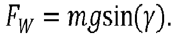
- Des Weiteren ergibt sich der Einfluss der Gewichtskraft in Abhängigkeit des Steigungswinkels γ wie folgt:

- Die Achslasten ergeben sich zu

- Die unterschiedlichen Einflüsse auf die Achslasten und deren Verschiebung untereinander sind somit bekannt.
- Über die Erfindung kann in Abhängigkeit der Stützlast F S über die Variation von lDB die Achslast linear verschoben werden.
- Typischerweise werden Radgewichte bis zu einem Gesamtgewicht von mRG = 600 kg an der Hinterachse angebracht. Bei einer Stützlastwirkung von mS = 4000 kg ergibt sich eine notwendige Längsverschiebung von

Claims (10)
- Anhängevorrichtung (2) für ein landwirtschaftliches Arbeitsfahrzeug (1) umfassend ein Kupplungsglied (14), dadurch gekennzeichnet, dass das Kupplungsglied (14) verschiebbar angeordnet ist und mit einem Aktor (3) zur Verschiebung in Verbindung steht.
- Anhängevorrichtung nach Anspruch 1, dadurch gekennzeichnet, dass das Kupplungsglied (14) in und entgegen der Fahrtrichtung vorzugsweise weitgehend horizontal verschiebbar angeordnet ist.
- Anhängevorrichtung nach Anspruch 1 oder 2, dadurch gekennzeichnet, dass der Aktor (3) einen Arbeitszylinder, vorzugsweise einen Pneumatikzylinder und/oder einen Hydraulikzylinder zur Verschiebung umfasst.
- Anhängevorrichtung nach einem der Ansprüche 1 bis 3, dadurch gekennzeichnet, dass es sich bei dem Kupplungsglied (14) um eine Kugelkopfkupplung handelt.
- Anhängevorrichtung nach einem der Ansprüche 1 bis 4, dadurch gekennzeichnet, dass das Kupplungsglied (14) mit einem Halteelement (15) in Verbindung steht.
- Anhängevorrichtung nach einem der Ansprüche 1 bis 5, dadurch gekennzeichnet, dass die Anhängevorrichtung 2 ein Führungselement (16) für die Verschiebung aufweist.
- Anhängevorrichtung nach Anspruch 5 und 6, dadurch gekennzeichnet, dass das Halteelement (15) in dem Führungselement (16) verschieblich angeordnet ist.
- Anhängevorrichtung nach einem der Ansprüche 1 bis 7, dadurch gekennzeichnet, dass das Kupplungsglied (14) stufenlos verschiebbar ist.
- Anhängevorrichtung nach einem der Ansprüche 1 bis 8, dadurch gekennzeichnet, dass die Vorrichtung mindestens einen Sensor 9, 10 und mindestens eine Einheit umfasst, zur Anpassung einer Position des Kupplungsgliedes (14).
- Verfahren zur Anpassung einer Position eines Kupplungsgliedes (14) einer Anhängevorrichtung (2) eines Arbeitsfahrzeugs (1), insbesondere einer Anhängevorrichtung (2) nach einem der Ansprüche 1 bis 9, mit folgenden Schritten:Erfassen von Daten,Anpassung der Position des Kupplungsgliedes (14) in Abhängigkeit der Daten.
Applications Claiming Priority (1)
| Application Number | Priority Date | Filing Date | Title |
|---|---|---|---|
| DE102017212047.9A DE102017212047A1 (de) | 2017-07-13 | 2017-07-13 | Anhängevorrichtung |
Publications (2)
| Publication Number | Publication Date |
|---|---|
| EP3427560A1 true EP3427560A1 (de) | 2019-01-16 |
| EP3427560B1 EP3427560B1 (de) | 2024-01-03 |
Family
ID=62916478
Family Applications (1)
| Application Number | Title | Priority Date | Filing Date |
|---|---|---|---|
| EP18182757.7A Active EP3427560B1 (de) | 2017-07-13 | 2018-07-10 | Anhängevorrichtung |
Country Status (3)
| Country | Link |
|---|---|
| US (1) | US10940727B2 (de) |
| EP (1) | EP3427560B1 (de) |
| DE (1) | DE102017212047A1 (de) |
Families Citing this family (4)
| Publication number | Priority date | Publication date | Assignee | Title |
|---|---|---|---|---|
| WO2018126324A1 (en) * | 2017-01-05 | 2018-07-12 | Jimmy Vigneault | Scraping device for clearing a roadway surface |
| US12082516B2 (en) * | 2020-12-28 | 2024-09-10 | Cnh Industrial America Llc | Automatic implement detection and management system |
| EP4458124A4 (de) * | 2021-12-28 | 2025-12-17 | Kubota Kk | Landwirtschaftliches arbeitsassistenzsystem, landwirtschaftliche maschine und landwirtschaftliche arbeitsassistenzvorrichtung |
| US11795642B1 (en) * | 2022-09-08 | 2023-10-24 | Ricky A. Weihl | Plow assembly |
Citations (5)
| Publication number | Priority date | Publication date | Assignee | Title |
|---|---|---|---|---|
| US20040021292A1 (en) * | 2002-08-01 | 2004-02-05 | Rodney Abair | Adjustable hitch and method of use |
| US20140343802A1 (en) * | 2011-07-22 | 2014-11-20 | Agco International Gmbh | Tractor control system |
| EP2893794A1 (de) * | 2013-12-20 | 2015-07-15 | AGCO International GmbH | Befestigung für landwirtschaftliches Arbeitsgerät |
| DE102014113448A1 (de) * | 2014-09-17 | 2016-03-17 | Jürgen Wagner | Zugfahrzeug und Anhängevorrichtung für ein Anbaugerät |
| US20170079191A1 (en) * | 2015-09-21 | 2017-03-23 | Meridian Manufacturing Inc. | Laterally moveable hitch assembly for a tractor |
Family Cites Families (13)
| Publication number | Priority date | Publication date | Assignee | Title |
|---|---|---|---|---|
| US3487448A (en) * | 1968-03-11 | 1969-12-30 | Deere & Co | Power operated swinging drawbar |
| US5236214A (en) * | 1992-04-06 | 1993-08-17 | Taylor-Made Equipment Co., Inc. | Underlift towing apparatus |
| EP0695655B1 (de) * | 1994-08-03 | 1998-04-01 | Deere & Company | Zugvorrichtung und Verriegelungsvorrichtung |
| US5997024A (en) * | 1998-04-07 | 1999-12-07 | Deere & Company | Hitch mechanism |
| US6871868B2 (en) * | 2002-07-30 | 2005-03-29 | Richard Pogue | Power hitch |
| DE10304978A1 (de) * | 2003-02-07 | 2004-08-19 | Deere & Company, Moline | Anhängevorrichtung für ein landwirtschaftliches oder industrielles Arbeitsfahrzeug |
| US20070138760A1 (en) * | 2005-11-23 | 2007-06-21 | Richard Granzow | Retractable Boat Trailer |
| US20100213687A1 (en) * | 2009-02-24 | 2010-08-26 | Patrick Kermit Mcdaniel | Trailer hitch assembly |
| DE102013211510A1 (de) | 2013-06-19 | 2014-12-24 | Deere & Company | Anhängevorrichtung |
| DE102013211516A1 (de) | 2013-06-19 | 2014-12-24 | Deere & Company | Anhängevorrichtung |
| GB201322746D0 (en) * | 2013-12-20 | 2014-02-05 | Agco Int Gmbh | Agricultural implement connection control |
| WO2016070245A1 (en) * | 2014-11-07 | 2016-05-12 | Tiainen Richard | Movable tow bar |
| US10821790B2 (en) * | 2018-04-20 | 2020-11-03 | Ford Global Technologies, Llc | Laterally articulating receiver system |
-
2017
- 2017-07-13 DE DE102017212047.9A patent/DE102017212047A1/de not_active Withdrawn
-
2018
- 2018-07-10 EP EP18182757.7A patent/EP3427560B1/de active Active
- 2018-07-13 US US16/034,595 patent/US10940727B2/en active Active
Patent Citations (5)
| Publication number | Priority date | Publication date | Assignee | Title |
|---|---|---|---|---|
| US20040021292A1 (en) * | 2002-08-01 | 2004-02-05 | Rodney Abair | Adjustable hitch and method of use |
| US20140343802A1 (en) * | 2011-07-22 | 2014-11-20 | Agco International Gmbh | Tractor control system |
| EP2893794A1 (de) * | 2013-12-20 | 2015-07-15 | AGCO International GmbH | Befestigung für landwirtschaftliches Arbeitsgerät |
| DE102014113448A1 (de) * | 2014-09-17 | 2016-03-17 | Jürgen Wagner | Zugfahrzeug und Anhängevorrichtung für ein Anbaugerät |
| US20170079191A1 (en) * | 2015-09-21 | 2017-03-23 | Meridian Manufacturing Inc. | Laterally moveable hitch assembly for a tractor |
Also Published As
| Publication number | Publication date |
|---|---|
| DE102017212047A1 (de) | 2019-01-17 |
| EP3427560B1 (de) | 2024-01-03 |
| US10940727B2 (en) | 2021-03-09 |
| US20190016184A1 (en) | 2019-01-17 |
Similar Documents
| Publication | Publication Date | Title |
|---|---|---|
| EP3427560B1 (de) | Anhängevorrichtung | |
| DE102011003791A1 (de) | System zum automatischen Einstellen eines Spaltraumes zwischen einem Motorwagen und einem daran angekuppelten Anhänger | |
| DE19951840A1 (de) | Anbauschnittstelle zur Kopplung von Arbeitsgeräten an ein Arbeitsfahrzeug | |
| DE102016106459A1 (de) | Arbeitsfahrzeug mit Knick-Gelenk-Lenkung und lastabhängiger Lenkwinkelbegrenzung | |
| EP2883435B1 (de) | Landwirtschaftliches Fahrzeuggespann | |
| WO2020025201A1 (de) | Gespann mit einer sattelzugmaschine und einem auflieger, sattelzugmaschine, auflieger und verfahren zur achslastverteilung bei einem gespann | |
| DE102011012089B4 (de) | Rangiersystem für einen mehrachsigen Anhänger und ein dazugehöriges Verfahren | |
| DE102007045912A1 (de) | Landwirtschaftliches Fahrzeug | |
| DE102014112534A1 (de) | Dynamisch regelbare Achslastverteilung für eine landwirtschaftliche Arbeitsmaschine | |
| DE102014008720B4 (de) | Schwerlastfahrzeug mit Staplerfunktion | |
| DE102012015554B4 (de) | Muldenkipper mit einer Kippermulde | |
| EP2239188B9 (de) | Schwanenhals für ein Fahrzeug, insbesondere für ein Schwerlastfahrzeug | |
| DE19752958A1 (de) | Bodenschonendes, der seitwärtigen Arbeitsweise zugängliches landwirtschaftliches Fahrzeug | |
| DE102019206770A1 (de) | Hydrostatisches Getriebe, mobile Arbeitsmaschine mit dem Getriebe und Verfahren zur Steuerung des Getriebes | |
| DE102006004930A1 (de) | Mit einem Zugfahrzeug über einen Schwanenhals kuppelbares Schwerstlastfahrzeug | |
| DE102006046329B4 (de) | Arbeitsfahrzeug mit einer Kupplungsvorrichtung zum Anhängen eines Arbeitsgerätes | |
| DE202018000854U1 (de) | Funktionslaufwerk zum Anbau an Off Road Fahrzeuge | |
| DE102023112738A1 (de) | Anhängevorrichtung zum rangieren eines anhängers und fahrzeug mit einer anhängevorrichtung | |
| DE202009002339U1 (de) | Abschleppvorrichtung | |
| DE10346299A1 (de) | Lenkeinrichtung für eine Tandemachse | |
| DE2039668A1 (de) | Fahrzeug,insbesondere landwirtschaftlich nutzbares Motorfahrzeug | |
| EP1136426B1 (de) | Gabelstapler mit hebbarer Fahrerkabine | |
| DE102009016725B4 (de) | Schwanenhals für ein Fahrzeug, insbesondere für ein Schwerlastfahrzeug | |
| EP3311640A1 (de) | Anhängevorrichtung für ein landwirtschaftliches zugfahrzeug und ein verfahren zu deren betrieb | |
| DE102015115696A1 (de) | Anhängevorrichtung für eine landwirtschaftliche Maschinenanordnung |
Legal Events
| Date | Code | Title | Description |
|---|---|---|---|
| PUAI | Public reference made under article 153(3) epc to a published international application that has entered the european phase |
Free format text: ORIGINAL CODE: 0009012 |
|
| STAA | Information on the status of an ep patent application or granted ep patent |
Free format text: STATUS: THE APPLICATION HAS BEEN PUBLISHED |
|
| AK | Designated contracting states |
Kind code of ref document: A1 Designated state(s): AL AT BE BG CH CY CZ DE DK EE ES FI FR GB GR HR HU IE IS IT LI LT LU LV MC MK MT NL NO PL PT RO RS SE SI SK SM TR |
|
| AX | Request for extension of the european patent |
Extension state: BA ME |
|
| STAA | Information on the status of an ep patent application or granted ep patent |
Free format text: STATUS: REQUEST FOR EXAMINATION WAS MADE |
|
| 17P | Request for examination filed |
Effective date: 20190716 |
|
| RBV | Designated contracting states (corrected) |
Designated state(s): AL AT BE BG CH CY CZ DE DK EE ES FI FR GB GR HR HU IE IS IT LI LT LU LV MC MK MT NL NO PL PT RO RS SE SI SK SM TR |
|
| STAA | Information on the status of an ep patent application or granted ep patent |
Free format text: STATUS: EXAMINATION IS IN PROGRESS |
|
| 17Q | First examination report despatched |
Effective date: 20211118 |
|
| REG | Reference to a national code |
Ref country code: DE Free format text: PREVIOUS MAIN CLASS: A01B0059000000 Ref country code: DE Ref legal event code: R079 Ref document number: 502018013892 Country of ref document: DE Free format text: PREVIOUS MAIN CLASS: A01B0059000000 Ipc: A01B0059042000 |
|
| GRAP | Despatch of communication of intention to grant a patent |
Free format text: ORIGINAL CODE: EPIDOSNIGR1 |
|
| STAA | Information on the status of an ep patent application or granted ep patent |
Free format text: STATUS: GRANT OF PATENT IS INTENDED |
|
| RIC1 | Information provided on ipc code assigned before grant |
Ipc: A01B 69/08 20060101ALI20230725BHEP Ipc: A01B 59/00 20060101ALI20230725BHEP Ipc: B60D 1/44 20060101ALI20230725BHEP Ipc: A01B 59/042 20060101AFI20230725BHEP |
|
| INTG | Intention to grant announced |
Effective date: 20230809 |
|
| GRAS | Grant fee paid |
Free format text: ORIGINAL CODE: EPIDOSNIGR3 |
|
| GRAA | (expected) grant |
Free format text: ORIGINAL CODE: 0009210 |
|
| STAA | Information on the status of an ep patent application or granted ep patent |
Free format text: STATUS: THE PATENT HAS BEEN GRANTED |
|
| AK | Designated contracting states |
Kind code of ref document: B1 Designated state(s): AL AT BE BG CH CY CZ DE DK EE ES FI FR GB GR HR HU IE IS IT LI LT LU LV MC MK MT NL NO PL PT RO RS SE SI SK SM TR |
|
| REG | Reference to a national code |
Ref country code: GB Ref legal event code: FG4D Free format text: NOT ENGLISH |
|
| REG | Reference to a national code |
Ref country code: DE Ref legal event code: R096 Ref document number: 502018013892 Country of ref document: DE |
|
| REG | Reference to a national code |
Ref country code: CH Ref legal event code: EP |
|
| REG | Reference to a national code |
Ref country code: IE Ref legal event code: FG4D Free format text: LANGUAGE OF EP DOCUMENT: GERMAN |
|
| REG | Reference to a national code |
Ref country code: LT Ref legal event code: MG9D |
|
| PG25 | Lapsed in a contracting state [announced via postgrant information from national office to epo] |
Ref country code: ES Free format text: LAPSE BECAUSE OF FAILURE TO SUBMIT A TRANSLATION OF THE DESCRIPTION OR TO PAY THE FEE WITHIN THE PRESCRIBED TIME-LIMIT Effective date: 20240103 |
|
| PG25 | Lapsed in a contracting state [announced via postgrant information from national office to epo] |
Ref country code: ES Free format text: LAPSE BECAUSE OF FAILURE TO SUBMIT A TRANSLATION OF THE DESCRIPTION OR TO PAY THE FEE WITHIN THE PRESCRIBED TIME-LIMIT Effective date: 20240103 |
|
| REG | Reference to a national code |
Ref country code: NL Ref legal event code: MP Effective date: 20240103 |
|
| PG25 | Lapsed in a contracting state [announced via postgrant information from national office to epo] |
Ref country code: NL Free format text: LAPSE BECAUSE OF FAILURE TO SUBMIT A TRANSLATION OF THE DESCRIPTION OR TO PAY THE FEE WITHIN THE PRESCRIBED TIME-LIMIT Effective date: 20240103 |
|
| PG25 | Lapsed in a contracting state [announced via postgrant information from national office to epo] |
Ref country code: NL Free format text: LAPSE BECAUSE OF FAILURE TO SUBMIT A TRANSLATION OF THE DESCRIPTION OR TO PAY THE FEE WITHIN THE PRESCRIBED TIME-LIMIT Effective date: 20240103 |
|
| PG25 | Lapsed in a contracting state [announced via postgrant information from national office to epo] |
Ref country code: IS Free format text: LAPSE BECAUSE OF FAILURE TO SUBMIT A TRANSLATION OF THE DESCRIPTION OR TO PAY THE FEE WITHIN THE PRESCRIBED TIME-LIMIT Effective date: 20240503 |
|
| PG25 | Lapsed in a contracting state [announced via postgrant information from national office to epo] |
Ref country code: LT Free format text: LAPSE BECAUSE OF FAILURE TO SUBMIT A TRANSLATION OF THE DESCRIPTION OR TO PAY THE FEE WITHIN THE PRESCRIBED TIME-LIMIT Effective date: 20240103 |
|
| PG25 | Lapsed in a contracting state [announced via postgrant information from national office to epo] |
Ref country code: GR Free format text: LAPSE BECAUSE OF FAILURE TO SUBMIT A TRANSLATION OF THE DESCRIPTION OR TO PAY THE FEE WITHIN THE PRESCRIBED TIME-LIMIT Effective date: 20240404 |
|
| PG25 | Lapsed in a contracting state [announced via postgrant information from national office to epo] |
Ref country code: HR Free format text: LAPSE BECAUSE OF FAILURE TO SUBMIT A TRANSLATION OF THE DESCRIPTION OR TO PAY THE FEE WITHIN THE PRESCRIBED TIME-LIMIT Effective date: 20240103 Ref country code: RS Free format text: LAPSE BECAUSE OF FAILURE TO SUBMIT A TRANSLATION OF THE DESCRIPTION OR TO PAY THE FEE WITHIN THE PRESCRIBED TIME-LIMIT Effective date: 20240403 |
|
| PG25 | Lapsed in a contracting state [announced via postgrant information from national office to epo] |
Ref country code: CZ Free format text: LAPSE BECAUSE OF FAILURE TO SUBMIT A TRANSLATION OF THE DESCRIPTION OR TO PAY THE FEE WITHIN THE PRESCRIBED TIME-LIMIT Effective date: 20240103 |
|
| PG25 | Lapsed in a contracting state [announced via postgrant information from national office to epo] |
Ref country code: RS Free format text: LAPSE BECAUSE OF FAILURE TO SUBMIT A TRANSLATION OF THE DESCRIPTION OR TO PAY THE FEE WITHIN THE PRESCRIBED TIME-LIMIT Effective date: 20240403 Ref country code: NO Free format text: LAPSE BECAUSE OF FAILURE TO SUBMIT A TRANSLATION OF THE DESCRIPTION OR TO PAY THE FEE WITHIN THE PRESCRIBED TIME-LIMIT Effective date: 20240403 Ref country code: LT Free format text: LAPSE BECAUSE OF FAILURE TO SUBMIT A TRANSLATION OF THE DESCRIPTION OR TO PAY THE FEE WITHIN THE PRESCRIBED TIME-LIMIT Effective date: 20240103 Ref country code: IS Free format text: LAPSE BECAUSE OF FAILURE TO SUBMIT A TRANSLATION OF THE DESCRIPTION OR TO PAY THE FEE WITHIN THE PRESCRIBED TIME-LIMIT Effective date: 20240503 Ref country code: HR Free format text: LAPSE BECAUSE OF FAILURE TO SUBMIT A TRANSLATION OF THE DESCRIPTION OR TO PAY THE FEE WITHIN THE PRESCRIBED TIME-LIMIT Effective date: 20240103 Ref country code: GR Free format text: LAPSE BECAUSE OF FAILURE TO SUBMIT A TRANSLATION OF THE DESCRIPTION OR TO PAY THE FEE WITHIN THE PRESCRIBED TIME-LIMIT Effective date: 20240404 Ref country code: CZ Free format text: LAPSE BECAUSE OF FAILURE TO SUBMIT A TRANSLATION OF THE DESCRIPTION OR TO PAY THE FEE WITHIN THE PRESCRIBED TIME-LIMIT Effective date: 20240103 Ref country code: BG Free format text: LAPSE BECAUSE OF FAILURE TO SUBMIT A TRANSLATION OF THE DESCRIPTION OR TO PAY THE FEE WITHIN THE PRESCRIBED TIME-LIMIT Effective date: 20240103 |
|
| PG25 | Lapsed in a contracting state [announced via postgrant information from national office to epo] |
Ref country code: PL Free format text: LAPSE BECAUSE OF FAILURE TO SUBMIT A TRANSLATION OF THE DESCRIPTION OR TO PAY THE FEE WITHIN THE PRESCRIBED TIME-LIMIT Effective date: 20240103 Ref country code: PT Free format text: LAPSE BECAUSE OF FAILURE TO SUBMIT A TRANSLATION OF THE DESCRIPTION OR TO PAY THE FEE WITHIN THE PRESCRIBED TIME-LIMIT Effective date: 20240503 |
|
| PG25 | Lapsed in a contracting state [announced via postgrant information from national office to epo] |
Ref country code: SE Free format text: LAPSE BECAUSE OF FAILURE TO SUBMIT A TRANSLATION OF THE DESCRIPTION OR TO PAY THE FEE WITHIN THE PRESCRIBED TIME-LIMIT Effective date: 20240103 Ref country code: PT Free format text: LAPSE BECAUSE OF FAILURE TO SUBMIT A TRANSLATION OF THE DESCRIPTION OR TO PAY THE FEE WITHIN THE PRESCRIBED TIME-LIMIT Effective date: 20240503 Ref country code: PL Free format text: LAPSE BECAUSE OF FAILURE TO SUBMIT A TRANSLATION OF THE DESCRIPTION OR TO PAY THE FEE WITHIN THE PRESCRIBED TIME-LIMIT Effective date: 20240103 Ref country code: LV Free format text: LAPSE BECAUSE OF FAILURE TO SUBMIT A TRANSLATION OF THE DESCRIPTION OR TO PAY THE FEE WITHIN THE PRESCRIBED TIME-LIMIT Effective date: 20240103 |
|
| REG | Reference to a national code |
Ref country code: DE Ref legal event code: R097 Ref document number: 502018013892 Country of ref document: DE |
|
| PG25 | Lapsed in a contracting state [announced via postgrant information from national office to epo] |
Ref country code: DK Free format text: LAPSE BECAUSE OF FAILURE TO SUBMIT A TRANSLATION OF THE DESCRIPTION OR TO PAY THE FEE WITHIN THE PRESCRIBED TIME-LIMIT Effective date: 20240103 |
|
| PG25 | Lapsed in a contracting state [announced via postgrant information from national office to epo] |
Ref country code: SM Free format text: LAPSE BECAUSE OF FAILURE TO SUBMIT A TRANSLATION OF THE DESCRIPTION OR TO PAY THE FEE WITHIN THE PRESCRIBED TIME-LIMIT Effective date: 20240103 |
|
| PG25 | Lapsed in a contracting state [announced via postgrant information from national office to epo] |
Ref country code: EE Free format text: LAPSE BECAUSE OF FAILURE TO SUBMIT A TRANSLATION OF THE DESCRIPTION OR TO PAY THE FEE WITHIN THE PRESCRIBED TIME-LIMIT Effective date: 20240103 |
|
| PG25 | Lapsed in a contracting state [announced via postgrant information from national office to epo] |
Ref country code: SK Free format text: LAPSE BECAUSE OF FAILURE TO SUBMIT A TRANSLATION OF THE DESCRIPTION OR TO PAY THE FEE WITHIN THE PRESCRIBED TIME-LIMIT Effective date: 20240103 |
|
| PG25 | Lapsed in a contracting state [announced via postgrant information from national office to epo] |
Ref country code: SM Free format text: LAPSE BECAUSE OF FAILURE TO SUBMIT A TRANSLATION OF THE DESCRIPTION OR TO PAY THE FEE WITHIN THE PRESCRIBED TIME-LIMIT Effective date: 20240103 Ref country code: SK Free format text: LAPSE BECAUSE OF FAILURE TO SUBMIT A TRANSLATION OF THE DESCRIPTION OR TO PAY THE FEE WITHIN THE PRESCRIBED TIME-LIMIT Effective date: 20240103 Ref country code: RO Free format text: LAPSE BECAUSE OF FAILURE TO SUBMIT A TRANSLATION OF THE DESCRIPTION OR TO PAY THE FEE WITHIN THE PRESCRIBED TIME-LIMIT Effective date: 20240103 Ref country code: EE Free format text: LAPSE BECAUSE OF FAILURE TO SUBMIT A TRANSLATION OF THE DESCRIPTION OR TO PAY THE FEE WITHIN THE PRESCRIBED TIME-LIMIT Effective date: 20240103 Ref country code: DK Free format text: LAPSE BECAUSE OF FAILURE TO SUBMIT A TRANSLATION OF THE DESCRIPTION OR TO PAY THE FEE WITHIN THE PRESCRIBED TIME-LIMIT Effective date: 20240103 |
|
| PLBE | No opposition filed within time limit |
Free format text: ORIGINAL CODE: 0009261 |
|
| STAA | Information on the status of an ep patent application or granted ep patent |
Free format text: STATUS: NO OPPOSITION FILED WITHIN TIME LIMIT |
|
| 26N | No opposition filed |
Effective date: 20241007 |
|
| PG25 | Lapsed in a contracting state [announced via postgrant information from national office to epo] |
Ref country code: MC Free format text: LAPSE BECAUSE OF FAILURE TO SUBMIT A TRANSLATION OF THE DESCRIPTION OR TO PAY THE FEE WITHIN THE PRESCRIBED TIME-LIMIT Effective date: 20240103 |
|
| REG | Reference to a national code |
Ref country code: CH Ref legal event code: PL |
|
| PG25 | Lapsed in a contracting state [announced via postgrant information from national office to epo] |
Ref country code: LU Free format text: LAPSE BECAUSE OF NON-PAYMENT OF DUE FEES Effective date: 20240710 |
|
| PG25 | Lapsed in a contracting state [announced via postgrant information from national office to epo] |
Ref country code: LU Free format text: LAPSE BECAUSE OF NON-PAYMENT OF DUE FEES Effective date: 20240710 |
|
| PG25 | Lapsed in a contracting state [announced via postgrant information from national office to epo] |
Ref country code: BE Free format text: LAPSE BECAUSE OF NON-PAYMENT OF DUE FEES Effective date: 20240731 Ref country code: SI Free format text: LAPSE BECAUSE OF FAILURE TO SUBMIT A TRANSLATION OF THE DESCRIPTION OR TO PAY THE FEE WITHIN THE PRESCRIBED TIME-LIMIT Effective date: 20240103 Ref country code: CH Free format text: LAPSE BECAUSE OF NON-PAYMENT OF DUE FEES Effective date: 20240731 |
|
| REG | Reference to a national code |
Ref country code: BE Ref legal event code: MM Effective date: 20240731 |
|
| PG25 | Lapsed in a contracting state [announced via postgrant information from national office to epo] |
Ref country code: IE Free format text: LAPSE BECAUSE OF NON-PAYMENT OF DUE FEES Effective date: 20240710 |
|
| REG | Reference to a national code |
Ref country code: AT Ref legal event code: MM01 Ref document number: 1645790 Country of ref document: AT Kind code of ref document: T Effective date: 20240710 |
|
| PG25 | Lapsed in a contracting state [announced via postgrant information from national office to epo] |
Ref country code: FI Free format text: LAPSE BECAUSE OF FAILURE TO SUBMIT A TRANSLATION OF THE DESCRIPTION OR TO PAY THE FEE WITHIN THE PRESCRIBED TIME-LIMIT Effective date: 20240103 |
|
| PGFP | Annual fee paid to national office [announced via postgrant information from national office to epo] |
Ref country code: DE Payment date: 20250620 Year of fee payment: 8 |
|
| PGFP | Annual fee paid to national office [announced via postgrant information from national office to epo] |
Ref country code: IT Payment date: 20250721 Year of fee payment: 8 |
|
| PGFP | Annual fee paid to national office [announced via postgrant information from national office to epo] |
Ref country code: GB Payment date: 20250728 Year of fee payment: 8 |
|
| PG25 | Lapsed in a contracting state [announced via postgrant information from national office to epo] |
Ref country code: AT Free format text: LAPSE BECAUSE OF NON-PAYMENT OF DUE FEES Effective date: 20240710 |
|
| PGFP | Annual fee paid to national office [announced via postgrant information from national office to epo] |
Ref country code: FR Payment date: 20250725 Year of fee payment: 8 |
|
| PG25 | Lapsed in a contracting state [announced via postgrant information from national office to epo] |
Ref country code: CY Free format text: LAPSE BECAUSE OF FAILURE TO SUBMIT A TRANSLATION OF THE DESCRIPTION OR TO PAY THE FEE WITHIN THE PRESCRIBED TIME-LIMIT; INVALID AB INITIO Effective date: 20180710 |
|
| PG25 | Lapsed in a contracting state [announced via postgrant information from national office to epo] |
Ref country code: HU Free format text: LAPSE BECAUSE OF FAILURE TO SUBMIT A TRANSLATION OF THE DESCRIPTION OR TO PAY THE FEE WITHIN THE PRESCRIBED TIME-LIMIT; INVALID AB INITIO Effective date: 20180710 |