EP3427559A1 - Mounted rotatable plough - Google Patents
Mounted rotatable plough Download PDFInfo
- Publication number
- EP3427559A1 EP3427559A1 EP18182873.2A EP18182873A EP3427559A1 EP 3427559 A1 EP3427559 A1 EP 3427559A1 EP 18182873 A EP18182873 A EP 18182873A EP 3427559 A1 EP3427559 A1 EP 3427559A1
- Authority
- EP
- European Patent Office
- Prior art keywords
- turning
- plow frame
- plow
- einschwenkaktor
- check valve
- Prior art date
- Legal status (The legal status is an assumption and is not a legal conclusion. Google has not performed a legal analysis and makes no representation as to the accuracy of the status listed.)
- Granted
Links
- 238000001514 detection method Methods 0.000 claims abstract description 9
- 230000008878 coupling Effects 0.000 claims description 22
- 238000010168 coupling process Methods 0.000 claims description 22
- 238000005859 coupling reaction Methods 0.000 claims description 22
- 230000033001 locomotion Effects 0.000 claims description 22
- 230000002441 reversible effect Effects 0.000 claims description 10
- 238000000034 method Methods 0.000 claims description 8
- 230000008569 process Effects 0.000 claims description 8
- 230000007246 mechanism Effects 0.000 claims description 5
- 230000004044 response Effects 0.000 claims description 2
- 230000005540 biological transmission Effects 0.000 claims 1
- 230000000903 blocking effect Effects 0.000 description 4
- 239000000725 suspension Substances 0.000 description 3
- 230000001154 acute effect Effects 0.000 description 1
- 230000008859 change Effects 0.000 description 1
- 230000006835 compression Effects 0.000 description 1
- 238000007906 compression Methods 0.000 description 1
- 230000001419 dependent effect Effects 0.000 description 1
- 230000009977 dual effect Effects 0.000 description 1
- 230000002349 favourable effect Effects 0.000 description 1
- 230000010006 flight Effects 0.000 description 1
- 230000001617 migratory effect Effects 0.000 description 1
- 230000035939 shock Effects 0.000 description 1
- 238000010408 sweeping Methods 0.000 description 1
- 238000011144 upstream manufacturing Methods 0.000 description 1
- 238000003079 width control Methods 0.000 description 1
Images

Classifications
-
- A—HUMAN NECESSITIES
- A01—AGRICULTURE; FORESTRY; ANIMAL HUSBANDRY; HUNTING; TRAPPING; FISHING
- A01B—SOIL WORKING IN AGRICULTURE OR FORESTRY; PARTS, DETAILS, OR ACCESSORIES OF AGRICULTURAL MACHINES OR IMPLEMENTS, IN GENERAL
- A01B3/00—Ploughs with fixed plough-shares
- A01B3/36—Ploughs mounted on tractors
- A01B3/40—Alternating ploughs
- A01B3/42—Turn-wrest ploughs
- A01B3/421—Turn-wrest ploughs with a headstock frame made in one piece
-
- A—HUMAN NECESSITIES
- A01—AGRICULTURE; FORESTRY; ANIMAL HUSBANDRY; HUNTING; TRAPPING; FISHING
- A01B—SOIL WORKING IN AGRICULTURE OR FORESTRY; PARTS, DETAILS, OR ACCESSORIES OF AGRICULTURAL MACHINES OR IMPLEMENTS, IN GENERAL
- A01B15/00—Elements, tools, or details of ploughs
- A01B15/14—Frames
- A01B15/145—Frames the plough blades being connected to the plough beam for unisono adjustment of the furrow width
Definitions
- the present invention relates to a mounted rotary plow with a trestle for attachment to a tractor, a plow frame, which carries two rows of ploughshare and is rotatable about a horizontal turning axis, the ploughshare rows are adjustable by a Thomasbreitenaktor in their cutting width and the plow frame on a turn block, the order said lying turning axis is pivotally mounted on the trestle, pivotally mounted about a Einschwenkachse transverse to the turning axis and actuated by a pressure medium Einschwenkaktor for the turning operation in a turning position with reduced Querausladung, the Einschwenkaktor of a swivel angle control for different cutting widths in different stroke positions to achieve the desired turning position is controllable.
- the elongated plow frame In multi-turn or turning flights with a larger working width, the elongated plow frame usually extends more or less obliquely to the horizontal turning axis, which usually extends lying in the direction of travel. If the plow frame turned in the headlands around said turning axis to bring the previously unused row of plowshares in working position for the next tram, it comes through the inclined plow frame to a sweeping, a lot of space needed turning movement.
- Einschwenkzylinder or other pressure medium actuators can be used, which pivot the plow frame relative to the turning beam foreign energy.
- Einschwenkzylinder or other pressure medium actuators can be used, which pivot the plow frame relative to the turning beam foreign energy.
- Einschwenkzylinder or other pressure medium actuators have already been proposed to couple the Einschwenkzylinder to the pressure medium actuation of the turning cylinder, so that when Druckschbeetzleyung the turning cylinder and the Einschwenkzylinder is actuated.
- the plowshares can be adjusted in their cutting width, which may include, for example, an adjustment of the inclination of the plow frame and / or plowshares to the direction of travel.
- the present invention has the object to provide an improved mounted reversible plow of the type mentioned, which avoids the disadvantages of the prior art and further develops the latter in an advantageous manner.
- a pivoting of the plow frame which is easy to execute even with different cutting width settings, is to be made possible for the turning process.
- the pivoted-in turning position no longer be predetermined by a stop against which the Einschwenkaktor or connected to the plow frame component is driven, but the Einschwenkaktor hydraulically or pressure medium operated to hold in the stroke position corresponding to the desired turning position of the plow frame ,
- the shock loads as they occur when approaching a stop can be avoided and on the other hand in a simple control manner different stroke positions of the Einschwenkaktors be approached to compensate for different cutting width settings and regardless of the respective Setting the Thomasbreitenaktors to adjust the desired turning position for the plow frame.
- the swivel angle control comprises a detection device for detecting the pivot position of the plow frame relative to the turning block with respect to the Einschwenkachse and a check valve for shutting off the Einschwenkaktor adjusting pressure medium circuit for starting various turning and / or transport positions Einschwenkaktors depending on the detected pivot position of the plow frame.
- said detecting device may comprise a mechanical coupling between the turning block and the plow frame, which is connected to the blocking valve and pivoting movements of the plow frame relative to the turning block with respect to the Einschwenkachse in a valve actuator movement converts.
- a mechanical coupling can spend the check valve in its blocking position as soon as the plow frame is pivoted far enough into the center of the turning movement or close enough to the turning axis.
- the said check valve with respect to the Einschwenkachse rotatably mounted on the plow frame or a rigidly connected support member, so that the check valve participates the Einschwenkambaen the plow frame relative to the turning block.
- the aforementioned mechanical coupling can connect the check valve thus attached with the turning block, so that the mechanical coupling, which may be hinged to an actuating element of the check valve, converts pivoting movements of the plow frame relative to the turning valve actuation or valve actuating movement.
- a hinged coupling rod which can transmit tensile and compressive forces provided can be.
- a coupling rod may on the one hand articulated articulated on an adjusting lever of the check valve and on the other hand be hinged to the turning block when the check valve is pflugrahmenfest mounted, or hinged to the plow frame when the check valve is attached to the turn block.
- the mechanical coupling may also include a cable mechanism which is provided between the turning block and the plow frame and converts pivoting movements of the plow frame relative to the turning block with respect to the Einschwenkachse in a valve actuating movement of the check valve.
- the check valve mounted on the plow frame to join plow frame movements with respect to the Einschwenkachse the said cable mechanism can be hinged on the one hand on the check valve and its actuator and on the other hand hinged on the turn block, where appropriate.
- Deflection rollers or means for deflecting the Ventilstellseils provided may be to implement the said pivoting movements of the plow frame in adjusting movements of the cable mechanism, in particular such that the cable of the cable mechanism spends the check valve in the blocking position when the plow frame has reached the sufficiently pivoted turning and / or transport position.
- the detection means but also have a non-contact scanning sensor for detecting the pivot position of the plow frame relative to the turning block with respect to Einschwenkachse, wherein the pivoting angle control, a preferably electrically actuated shut-off valve which can be actuated in response to a sensor signal of said sensor.
- a non-contact scanning sensor for detecting the pivot position of the plow frame relative to the turning block with respect to Einschwenkachse
- the pivoting angle control a preferably electrically actuated shut-off valve which can be actuated in response to a sensor signal of said sensor.
- an angle sensor may measure the pivotal position of the plow frame relative to the turn block and actuate the check valve once a sufficiently small swing angle is achieved that indicates a plow frame sufficiently close to the turning center.
- the hydraulic or pressure medium-based rotation angle control function of the scanned Pflugrahmenschwenk ein is particularly suitable for complex adjustable rotary plows, where different adjustment options are given and the plow frame is articulated via a complex articulation on the turning block, there on the said pressure medium based rotation angle control with detection of Pflugrahmenschwenk ein the desired turning position of the plow frame can be approached independently of varying default settings of the various plow parameters, without it being necessary to adjust these various plow parameters for starting the turning position and to return again after turning.
- the plow frame can be articulated via a multi-articulated linkage on the turning block, which linkage in addition to the Einschwenkaktor at least one further, spaced apart Anlenkla may comprise articulated on the one hand hinged on the turning block and the other hand hinged to the plow frame or an intermediate frame.
- said articulation support together with the Einschwenkaktor form a hinge portion in the manner of a four-bar linkage, so that an adjustment of the Einschwenkaktors causes an adjustment of said four-bar linkage.
- At the said four-jointed portion of the plow frame can in turn be pivoted and pivoted about other Verstellaktoren, for example via a pre-furrow actuator and / or a cutting width actuator and / or a Switzerlandddlingaktor.
- the Einschwenkaktor can be operated independently of different positions of the said other Verstellaktoren to swing the plow frame in the turning position, without having to adjust the other Stellaktoren as said Thomasbreitenaktor, the Vorfurchenaktor or the Switzerlandyakaktor.
- Said Einschwenkaktor can advantageously be connected to the pressure medium supply of the turning reactor, by means of which the plow can be turned, in particular such that the Einschwenkaktor is acted upon with pressure medium when pressure is applied to the turning cylinder.
- Such a to the turning cylinder - or actuator tailed Druckstoffschbeetzyerung Einschwenkaktors may be formed, for example.
- the attached revolving plow 1 shown in the figures has in a conventional manner a trestle 2, for example, can be attached to a tractor, not shown, via a Dreiticiananlenkung with upper and lower links.
- the trestle 2 carries a plow frame 3, are attached to the two rows of plowshares 4, said plow frame 3 together with the ploughshare rows about a lying, pointing in the direction of travel turn axis 5 relative to the trestle 2 rotated and thus can be turned to alternately with to be able to plow a row of ploughshare or the other group of ploughshare.
- a turnbuckle 6 is rotatably mounted about the said turning axis 5 on the attachment block 2, wherein the turning block 6 can be turned by means of a turning actuator 7, for example in the form of a hydraulic cylinder, the turning block 6 essentially being 180 ° can be twisted.
- the plow frame 3 At the turning block 6 of the plow frame 3 is suspended and hinged adjustable, as will be explained, wherein the total elongated, in particular carrier-shaped plow frame 3 is inclined in each case, in particular at an acute angle to the turning axis 5 is employed, see. FIG. 1 and FIG. 2 .
- the plow frame 3 can be moved about a pivoting axis 8 into a less inclined turning position so that the plow frame 3 extends closer to the turning axis 5.
- said Einschwenkachse 8 may be a spatially relative to the turning block 6 fixed axis or a migratory axis, which may change its position relative to the turning block 6 in the manner of a Momentanwindpols.
- said pivoting-in axis 8 extends transversely to the turning axis 5, wherein said pivoting-in axis 8 can be oriented upright or approximately vertically in the working positions shown in the figures.
- the plow frame 3 can be suspended on the turn block 6 via a multi-articulated linkage 9, wherein the linkage 9 may comprise an articulation beam 10, on the one hand articulated about a pivot axis parallel to Einschwenkachse 8 on the turning block 6 and on the other hand articulated around a Axis parallel to Einschwenkachse 8 may be hinged to the plow frame 3 and an associated intermediate frame.
- the linkage 9 may comprise an articulation beam 10, on the one hand articulated about a pivot axis parallel to Einschwenkachse 8 on the turning block 6 and on the other hand articulated around a Axis parallel to Einschwenkachse 8 may be hinged to the plow frame 3 and an associated intermediate frame.
- a hydraulic cylinder form a four-bar linkage, via which the plow frame 3 or the associated intermediate frame relative to the turn block 6 is pivotable when said Einschwenkaktor 11 is adjusted.
- the plow frame 3 can be adjusted independently of the Einschwenkaktor 11 via other articulations and Stellaktoren. For example, via a pre-furrow actuator 12 and a Switzerlandyakddlingaktor 13, the pivotal position of the plow frame 3 relative to said intermediate frame 14 and / or the aforementioned four-joint in itself be further adjusted.
- a Thomasbreitenaktor 15 can continue to adjust the pivot position of the ploughshare 4 relative to the plow frame 3.
- said Einschwenkaktor 11 is controlled by a hydraulic rotation angle control 16, advantageously no stop must be approached, but the Einschwenkzylinder 11 can be hydraulically held in the respective desired stroke position to the associated turning position of the plow frame 3 hold.
- a check valve 18 may be provided, wherein the check valve 18, the inflow side and / or the outflow side Einschwenkaktors 11 and the associated pressure medium supply 17 can shut off.
- the said check valve 18 is in this case activated and operated in dependence on the inclination of the plow frame 3 relative to the turn block 6 with respect to the Einschwenkachse 8.
- a detection device 19 detects the inclination of the plow frame 3 relative to the turn block 6, wherein said detection device 19 can provide a mechanical scanning of the inclination.
- a mechanical coupling 20 may be provided between the turning block 6 and the plow frame 3 and connected to said blocking valve 18 in order to convert pivoting movements of the plow frame 3 relative to the turning block relative to the pivoting axis 8 into a valve actuating movement.
- said mechanical coupling 20 may have a tension and compression-resistant coupling rod 21, which hinged on the one hand at the pivot point of the Einschwenkaktors 11 on the turning block 6 and on the other hand hinged to an actuating lever 21 of the check valve 18, wherein said check valve 18 at the plow frame 3 may be attached.
- the actuating lever 21 of the attached to the plow frame 3 check valve 18 is adjusted when the plow frame 3 is pivoted relative to the turning block 6, since said coupling rod 21 is moved relative to the plow frame 3 and thus the actuating lever 22 is adjusted.
- the mechanical coupling 20 is advantageously configured such that the check valve 18 is released or opened, as long as the plow frame 3 is aligned in the illustrated operating position and similarly inclined angular positions, and the check valve is only brought into its shut-off position when the plow frame 3 pivoted far enough, that is almost parallel or only slightly opposite to the turning axis 5 is tilted.
- This Einschwenkvorgang is achieved by extending the Einschwenkaktors 11.
Abstract
Die vorliegende Erfindung betrifft einen Anbaudrehpflug mit einem Anbaubock zum Anbau an einen Schlepper, einem Pflugrahmen, der zwei Pflugscharreihen trägt und um eine liegende Wendeachse drehbar ist, wobei die Pflugscharreihen durch einen Schnittbreitenaktor in ihrer Schnittbreite verstellbar sind und der Pflugrahmen an einem Wendebock, der um die genannte liegende Wendeachse schwenkbar am Anbaubock gelagert ist, um eine Einschwenkachse quer zur Wendeachse einschwenkbar gelagert und durch einen Druckmittel betätigten Einschwenkaktor für den Wendevorgang in eine Wendestellung mit verringerter Querausladung einschwenkbar ist, wobei der Einschwenkaktor von einer Schwenkwinkelsteuerung für verschiedene Schnittbreiten in verschiedene Hubstellungen zum Erreichen der gewünschten Wendestellung steuerbar ist. Erfindungsgemäß umfasst die Schwenkwinkelsteuerung eine Erfassungseinrichtung zum Erfassen der Schwenkstellung des Pflugrahmens relativ zum Wendebock bezüglich der Einschwenkachse und ein Sperrventil zum Absperren des den Einschwenkaktor verstellenden Druckmittelkreises zum Anfahren verschiedener Wende- und/oder Transportstellungen des Einschwenkaktors in Abhängigkeit der erfassten Schwenkstellung des Pflugrahmens.

Description
Die vorliegende Erfindung betrifft einen Anbaudrehpflug mit einem Anbaubock zum Anbau an einen Schlepper, einem Pflugrahmen, der zwei Pflugscharreihen trägt und um eine liegende Wendeachse drehbar ist, wobei die Pflugscharreihen durch einen Schnittbreitenaktor in ihrer Schnittbreite verstellbar sind und der Pflugrahmen an einem Wendebock, der um die genannte liegende Wendeachse schwenkbar am Anbaubock gelagert ist, um eine Einschwenkachse quer zur Wendeachse einschwenkbar gelagert und durch einen Druckmittel betätigten Einschwenkaktor für den Wendevorgang in eine Wendestellung mit verringerter Querausladung einschwenkbar ist, wobei der Einschwenkaktor von einer Schwenkwinkelsteuerung für verschiedene Schnittbreiten in verschiedene Hubstellungen zum Erreichen der gewünschten Wendestellung steuerbar ist.The present invention relates to a mounted rotary plow with a trestle for attachment to a tractor, a plow frame, which carries two rows of ploughshare and is rotatable about a horizontal turning axis, the ploughshare rows are adjustable by a Schnittbreitenaktor in their cutting width and the plow frame on a turn block, the order said lying turning axis is pivotally mounted on the trestle, pivotally mounted about a Einschwenkachse transverse to the turning axis and actuated by a pressure medium Einschwenkaktor for the turning operation in a turning position with reduced Querausladung, the Einschwenkaktor of a swivel angle control for different cutting widths in different stroke positions to achieve the desired turning position is controllable.
Bei mehrscharigen Dreh- bzw. Wendepflügen mit größerer Arbeitsbreite erstreckt sich der längliche Pflugrahmen üblicherweise mehr oder minder schräg zur liegenden Wendeachse, die sich üblicherweise liegend in Fahrtrichtung erstreckt. Wird der Pflugrahmen im Vorgewende um die genannte Wendeachse gedreht, um für die nächste Fahrgasse die zuvor nicht benutzte Pflugscharreihe in Arbeitsstellung zu bringen, kommt es durch den schrägstehenden Pflugrahmen zu einer ausgreifenden, viel Platz benötigenden Wendebewegung. Je schräger sich der Pflugrahmen zur Wendeachse erstreckt, desto größer wird der Abstand der am hinteren Ende des Pflugrahmens befestigten Pflugschare von der Wendeachse, sodass sich einerseits ein großer Hebelarm und damit ein großes Wendemoment ergibt, das zu starken Beanspruchungen der Anlenk- und Lagerstruktur des Pflugs führt und hohe Stellkräfte des Wendeaktors benötigt. Zum anderen kommt es zu stark ausgreifenden Bewegungen, was einerseits zu einem Einstechen in den Boden oder andererseits zum Anschlagen an seitlichen Begrenzungen führen kann.In multi-turn or turning flights with a larger working width, the elongated plow frame usually extends more or less obliquely to the horizontal turning axis, which usually extends lying in the direction of travel. If the plow frame turned in the headlands around said turning axis to bring the previously unused row of plowshares in working position for the next tram, it comes through the inclined plow frame to a sweeping, a lot of space needed turning movement. The more obliquely the plow frame extends to the turning axis, the greater the distance between the plowshares attached to the rear end of the plow frame of the turning axis, so that on the one hand, a large lever arm and thus a large turning moment results, the excessive stress on the articulation and bearing structure of the plow leads and high forces of the agitator needed. On the other hand, it comes to strong outstretched movements, which on the one hand can lead to a piercing in the ground or on the other hand to strike on lateral boundaries.
Es wurde deshalb bereits vorgeschlagen, den Pflugrahmen für den Wendevorgang oder auch zum Zwecke des Transports um eine Einschwenkachse quer zur Wendeachse einzuschwenken, um den Pflugrahmen näher an die Wendeachse zu bringen bzw. die Ausladung quer zur Wendeachse zu verringern, was im Wesentlichen dadurch erreicht wird, dass der Schrägstellungswinkel des länglichen Pflugrahmens gegenüber der Wendeachse verkleinert wird. Je nach Aufhängung bzw. Anlenkung des Pflugrahmens bspw. über eine Mehrgelenksstruktur kann dies auch eine Querbewegung des Pflugrahmens beinhalten, die den Pflugrahmen und die daran angebauten Pflugscharreihen näher in das Zentrum der Wendebewegung bringt.It has therefore already been proposed to pivot the plow frame for the turning process or for the purpose of transport about a Einschwenkachse transversely to the turning axis to bring the plow frame closer to the turning axis or to reduce the radius transversely to the turning axis, which is essentially achieved by in that the skew angle of the oblong plow frame is reduced relative to the turning axis. Depending on the suspension or articulation of the plow frame, for example, via a multi-joint structure, this may also include a transverse movement of the plow frame, which brings the plow frame and attached thereto Pflugscharreihen closer to the center of the turning movement.
Für das Einschwenken des Pflugrahmens vor dem bzw. für den Wendevorgang können Einschwenkzylinder oder andere Druckmittelaktoren Verwendung finden, die den Pflugrahmen gegenüber dem Wendebock Fremdenergie betätigt einschwenken. Dabei wurde bspw. bereits vorgeschlagen, den Einschwenkzylinder an die Druckmittelbetätigung des Wendezylinders anzukoppeln, sodass bei Druckmittelbeaufschlagung des Wendezylinders auch der Einschwenkzylinder betätigt wird.For the pivoting of the plow frame before or for the turning operation Einschwenkzylinder or other pressure medium actuators can be used, which pivot the plow frame relative to the turning beam foreign energy. In this case, for example, has already been proposed to couple the Einschwenkzylinder to the pressure medium actuation of the turning cylinder, so that when Druckmittelbeaufschlagung the turning cylinder and the Einschwenkzylinder is actuated.
Ein Problem hierbei ergibt sich, wenn der Drehpflug eine Schnittbreitenverstellung besitzt, wie dies bei moderneren Drehpflügen regelmäßig der Fall ist. Durch den Schnittbreitenaktor können die Pflugschare in ihrer Schnittbreite verstellt werden, was bspw. eine Verstellung der Schrägstellung des Pflugrahmens und/oder der Pflugschare zur Fahrtrichtung beinhaltet kann. Je nachdem, in welcher Schnitt- bzw. Arbeitsbreite der Pflug gefahren wird, muss der vorgenannte Einschwenkzylinder unterschiedliche Stellwege zurücklegen, um den Pflugrahmen in die gewünschte Wendestellung zu verbringen, da der Einschwenkaktor den Pflugrahmen hierzu unterschiedlich weit verschwenken muss.A problem here arises when the rotary plow has a cutting width adjustment, as is the case regularly with modern rotary plows. Through the Schnittbreitenaktor the plowshares can be adjusted in their cutting width, which may include, for example, an adjustment of the inclination of the plow frame and / or plowshares to the direction of travel. Depending on the cutting or working width of the plow is driven, the aforementioned Einschwenkzylinder cover different travel paths to spend the plow frame in the desired turning position, since the Einschwenkaktor the plow frame this has to pivot different degrees.
Um die gewünschte Wendestellung anfahren zu können, ist es bislang üblich, den Einschwenkzylinder gegen Anschläge fahren zu lassen, die eine jeweilige Endstellung des Einschwenkaktors mechanisch vorgeben. Die Anschläge können dabei verstellt werden, um je nach Schnittbreite die benötigte Hubendstellung des Einschwenkaktors passend einstellen zu können. Bei hydraulischer Schnittbreitenverstellung, die eine häufigere Verstellung zulässt, ist dies jedoch mühsam, da jedes Mal die Anschläge neu eingestellt werden müssten, wenn die Schnittbreite verstellt wird.To be able to approach the desired turning position, it has hitherto been customary to let the pivoting cylinder travel against stops which mechanically predetermine a respective end position of the pivoting actuator. The stops can be adjusted in order to adjust the required stroke end position of the Einschwenkaktors suitable depending on the cutting width. With hydraulic cutting width adjustment, which allows a more frequent adjustment, but this is tedious, since each time the stops would have to be readjusted when the cutting width is adjusted.
In der Schrift
Weiterhin wurde bereits vorgeschlagen, die Einschwenkbewegung nicht mittels eines separaten Einschwenkaktors zu bewerkstelligen, sondern über eine gesteuerte Bewegung des Schnittbreitenaktors. Hierbei werden jedoch sämtliche Schnittbreitengelenke bewegt. Zudem muss nach dem Wendevorgang die Schnittbreitenverstellung wieder zurück in ihre Arbeitsstellung gefahren werden, wozu sich die Schnittbreiten-Steuervorrichtung die zuvor verlassene Stellung gemerkt haben muss und eine relativ komplexe, hydraulische Ansteuerung des Schnittbreitenaktors erforderlich ist.Furthermore, it has been proposed not to accomplish the Einschwenkbewegung by means of a separate Einschwenkaktors, but via a controlled movement of the Schnittbreitenaktors. In this case, however, all cutting width joints are moved. In addition, after the turning process, the cutting width adjustment must be moved back to its working position, for which the cutting width control device have noticed the previously abandoned position and a relatively complex, hydraulic control of the Schnittbreitenaktors is required.
Hiervon ausgehend liegt der vorliegenden Erfindung die Aufgabe zugrunde, einen verbesserten Anbaudrehpflug der genannten Art zu schaffen, der Nachteile des Standes der Technik vermeidet und letzteren in vorteilhafter Weise weiterbildet. Insbesondere soll ein auch bei verschiedenen Schnittbreiteneinstellungen einfach auszuführendes Einschwenken des Pflugrahmens für den Wendevorgang ermöglicht werden.Proceeding from this, the present invention has the object to provide an improved mounted reversible plow of the type mentioned, which avoids the disadvantages of the prior art and further develops the latter in an advantageous manner. In particular, a pivoting of the plow frame, which is easy to execute even with different cutting width settings, is to be made possible for the turning process.
Diese Aufgabe wird durch einen Anbaudrehpflug gemäß Anspruch 1 gelöst. Bevorzugte Ausgestaltungen der Erfindung sind Gegenstand der abhängigen Ansprüche.This object is achieved by a mounted turntable according to claim 1. Preferred embodiments of the invention are the subject of the dependent claims.
Es wird also vorgeschlagen, die eingeschwenkte Wendestellung nicht mehr durch einen Anschlag vorzugeben, gegen den der Einschwenkaktor oder ein mit dem Pflugrahmen verbundenes Bauteil gefahren wird, sondern den Einschwenkaktor hydraulisch bzw. Druckmittel betätigt in der Hubstellung zu halten, die der gewünschten Wendestellung des Pflugrahmens entspricht. Durch eine hydraulische bzw. Druckmittel betätigte Verriegelung des Einschwenkaktors können einerseits die stoßhaften Belastungen, wie sie beim Anfahren eines Anschlags auftreten, vermieden werden und andererseits in steuerungstechnisch einfacher Weise verschiedene Hubstellungen des Einschwenkaktors angefahren werden, um verschiedene Schnittbreiteneinstellungen zu kompensieren bzw. unabhängig von der jeweiligen Stellung des Schnittbreitenaktors die gewünschte Wendestellung für den Pflugrahmen einstellen zu können. Erfindungsgemäß umfasst die Schwenkwinkelsteuerung eine Erfassungseinrichtung zum Erfassen der Schwenkstellung des Pflugrahmens relativ zum Wendebock bezüglich der Einschwenkachse und ein Sperrventil zum Absperren des den Einschwenkaktor verstellenden Druckmittelkreises zum Anfahren verschiedener Wende- und/oder Transportstellungen des Einschwenkaktors in Abhängigkeit der erfassten Schwenkstellung des Pflugrahmens. Durch eine solche Erfassung der Pflugrahmenschwenkstellung und der Ansteuerung des Einschwenkzylinders in Abhängigkeit hiervon kann unabhängig von weiteren jeweils gefahrenen Pflugeinstellungen wie Schnittbreite, Vorfurchenbreite oder Zugpunkt der Pflugrahmen für den Wendevorgang und/oder für den Transport in eine jeweils gewünschte Wendestellung eingeschwenkt und der Einschwenkaktor in die hierzu erforderliche Hubstellung gefahren werden.It is therefore proposed that the pivoted-in turning position no longer be predetermined by a stop against which the Einschwenkaktor or connected to the plow frame component is driven, but the Einschwenkaktor hydraulically or pressure medium operated to hold in the stroke position corresponding to the desired turning position of the plow frame , By a hydraulic or pressure medium actuated locking the Einschwenkaktors on the one hand, the shock loads, as they occur when approaching a stop can be avoided and on the other hand in a simple control manner different stroke positions of the Einschwenkaktors be approached to compensate for different cutting width settings and regardless of the respective Setting the Schnittbreitenaktors to adjust the desired turning position for the plow frame. According to the invention, the swivel angle control comprises a detection device for detecting the pivot position of the plow frame relative to the turning block with respect to the Einschwenkachse and a check valve for shutting off the Einschwenkaktor adjusting pressure medium circuit for starting various turning and / or transport positions Einschwenkaktors depending on the detected pivot position of the plow frame. By such a detection of the Pflugrahmenschwenkstellung and the control of the Einschwenkzylinders in dependence thereof may be independent of further respectively driven plow settings such as cutting width, furrow width or traction point of the plow frame for the turning process and / or for transport in a respective desired turning position pivoted and the Einschwenkaktor be driven into the required lifting position.
Um eine einfache, robuste Abtastung der Pflugrahmenschwenkstellung und gleichzeitig Betätigung des Sperrventils zu erreichen, kann in vorteilhafter Weiterbildung der Erfindung die genannte Erfassungseinrichtung eine mechanische Koppelung zwischen dem Wendebock und dem Pflugrahmen umfassen, die an das Sperrventil angebunden ist und Schwenkbewegungen des Pflugrahmens relativ zu dem Wendebock bezüglich der Einschwenkachse in eine Ventilstellbewegung umsetzt. Insbesondere kann eine solche mechanische Koppelung das Sperrventil in seine Sperrstellung verbringen, sobald der Pflugrahmen weit genug in das Zentrum der Wendebewegung bzw. nahe genug an die Wendeachse eingeschwenkt ist.In order to achieve a simple, robust scanning of the plow frame pivoting position and at the same time actuation of the stop valve, in an advantageous development of the invention said detecting device may comprise a mechanical coupling between the turning block and the plow frame, which is connected to the blocking valve and pivoting movements of the plow frame relative to the turning block with respect to the Einschwenkachse in a valve actuator movement converts. In particular, such a mechanical coupling can spend the check valve in its blocking position as soon as the plow frame is pivoted far enough into the center of the turning movement or close enough to the turning axis.
In vorteilhafter Weiterbildung kann das genannte Sperrventil bezüglich der Einschwenkachse drehfest an dem Pflugrahmen oder einem damit starr verbundenen Trägerteil befestigt sein, sodass das Sperrventil die Einschwenkbewegungen des Pflugrahmens relativ zum Wendebock mitmacht. Die vorgenannte mechanische Koppelung kann das solchermaßen angebrachte Sperrventil mit dem Wendebock verbinden, sodass die mechanische Koppelung, die an einem Betätigungselement des Sperrventils angelenkt sein kann, Schwenkbewegungen des Pflugrahmens relativ zum Wendeventilbetätigung bzw. Ventilstellbewegung umsetzt.In an advantageous embodiment, the said check valve with respect to the Einschwenkachse rotatably mounted on the plow frame or a rigidly connected support member, so that the check valve participates the Einschwenkbewegungen the plow frame relative to the turning block. The aforementioned mechanical coupling can connect the check valve thus attached with the turning block, so that the mechanical coupling, which may be hinged to an actuating element of the check valve, converts pivoting movements of the plow frame relative to the turning valve actuation or valve actuating movement.
In kinematischer Umkehrung wäre es ebenfalls möglich, das Sperrventil am Wendebock anzuordnen und über die Koppelung, die in diesem Falle am Pflugrahmen oder einem damit verbundenen Trägerteil angelenkt sein kann, an die Pflugrahmenbewegungen anzubinden.In kinematic reversal, it would also be possible to arrange the check valve on the turning block and connect to the plow frame movements via the coupling, which may be articulated in this case on the plow frame or an associated support member.
Die genannte mechanische Koppelung kann hierbei grundsätzlich unterschiedlich ausgebildet sein, wobei in vorteilhafter Weiterbildung der Erfindung eine gelenkig angelenkte Koppelstange, die Zug- und Druckkräfte übertragen kann, vorgesehen sein kann. Eine solche Koppelstange kann einerseits gelenkig an einem Verstellhebel des Sperrventils angelenkt und andererseits an dem Wendebock angelenkt sein, wenn das Sperrventil pflugrahmenfest montiert ist, oder am Pflugrahmen angelenkt sein, wenn das Sperrventil am Wendebock befestigt ist.The said mechanical coupling can in principle be designed differently, wherein in an advantageous embodiment of the invention, a hinged coupling rod, which can transmit tensile and compressive forces provided can be. Such a coupling rod may on the one hand articulated articulated on an adjusting lever of the check valve and on the other hand be hinged to the turning block when the check valve is pflugrahmenfest mounted, or hinged to the plow frame when the check valve is attached to the turn block.
Insbesondere kann es günstig sein, den genannten Verstellhebel an dem Anlenkpunkt des Einschwenkaktors anzulenken, mit dem der Einlenkaktor gelenkig am Wendebock oder einem damit verbundenen Einschwenkträger angelenkt ist, sodass der genannte Anlenkpunkt des Einschwenkaktors eine Doppelfunktion übernimmt, nämlich einerseits den Einschwenkaktor anlenkt und andererseits die genannte Koppelstange anlenkt. Hierdurch kann eine platzsparende Ausbildung erzielt werden, während gleichzeitig die Stellbewegungen des Einschwenkaktors unmittelbar in eine Koppelstellbewegung umgesetzt werden.In particular, it may be favorable to articulate said adjusting lever at the articulation point of the Einschwenkaktors, with the Einlenkaktor articulated on the turn block or an associated Einschwenkträger, so that the pivot point of the Einschwenkaktors takes on a dual function, namely on the one hand the Einschwenkaktor and on the other hand the aforementioned Coupling rod articulates. In this way, a space-saving training can be achieved, while at the same time the positioning movements of the Einschwenkaktors are converted directly into a coupling actuating movement.
Alternativ oder zusätzlich zu einer solchen Zug- und Druckkräfte übertragenden Koppelstange kann die mechanische Koppelung auch einen Seilzugmechanismus umfassen, der zwischen dem Wendebock und dem Pflugrahmen vorgesehen ist und Schwenkbewegungen des Pflugrahmens relativ zum Wendebock bezüglich der Einschwenkachse in eine Ventilstellbewegung des Sperrventils umsetzt. Ist in der vorgenannten Weise das Sperrventil am Pflugrahmen montiert, um Pflugrahmenbewegungen bezüglich der Einschwenkachse mitzumachen, kann der genannte Seilzugmechanismus einerseits an dem Sperrventil bzw. dessen Stellglied angelenkt und andererseits am Wendebock angelenkt sein, wobei ggfs. Umlenkrollen oder -mittel zum Umlenken des Ventilstellseils vorgesehen sein können, um die genannten Schwenkbewegungen des Pflugrahmens in Stellbewegungen des Seilzugmechanismus umzusetzen, insbesondere derart, dass das Seil des Seilzugmechanismus das Sperrventil in die sperrende Stellung verbringt, wenn der Pflugrahmen die ausreichend eingeschwenkte Wende- und/oder Transportstellung erreicht hat.Alternatively or in addition to such a tensile and compressive forces transmitted coupling rod, the mechanical coupling may also include a cable mechanism which is provided between the turning block and the plow frame and converts pivoting movements of the plow frame relative to the turning block with respect to the Einschwenkachse in a valve actuating movement of the check valve. Is in the aforementioned manner, the check valve mounted on the plow frame to join plow frame movements with respect to the Einschwenkachse, the said cable mechanism can be hinged on the one hand on the check valve and its actuator and on the other hand hinged on the turn block, where appropriate. Deflection rollers or means for deflecting the Ventilstellseils provided may be to implement the said pivoting movements of the plow frame in adjusting movements of the cable mechanism, in particular such that the cable of the cable mechanism spends the check valve in the blocking position when the plow frame has reached the sufficiently pivoted turning and / or transport position.
Alternativ oder zusätzlich zu einer solchen mechanischen Abtastung der Pflugrahmenschwenkstellung und Betätigung des Sperrventils kann die Erfassungseinrichtung aber auch einen berührungslos abtastenden Sensor zum Erfassen der Schwenkstellung des Pflugrahmens relativ zum Wendebock bezüglich der Einschwenkachse aufweisen, wobei die Schwenkwinkelsteuerung ein vorzugsweise elektrisch betätigbares Sperrventil, das in Abhängigkeit eines Sensorsignals des genannten Sensors betätigbar ist, aufweisen kann. Beispielsweise kann ein Winkelsensor die Schwenkstellung des Pflugrahmens relativ zum Wendebock messen bzw. erfassen und das Sperrventil betätigt werden, sobald ein ausreichend kleiner Schwenkwinkel erreicht wird, der eine ausreichend nahe im Wendezentrum liegenden Pflugrahmen angibt.Alternatively, or in addition to such mechanical scanning of the plow frame pivot position and actuation of the check valve, the detection means but also have a non-contact scanning sensor for detecting the pivot position of the plow frame relative to the turning block with respect to Einschwenkachse, wherein the pivoting angle control, a preferably electrically actuated shut-off valve which can be actuated in response to a sensor signal of said sensor. For example, an angle sensor may measure the pivotal position of the plow frame relative to the turn block and actuate the check valve once a sufficiently small swing angle is achieved that indicates a plow frame sufficiently close to the turning center.
Die hydraulische bzw. Druckmittel basierte Drehwinkelsteuerung in Abhängigkeit der abgetasteten Pflugrahmenschwenkstellung ist insbesondere für komplexer verstellbare Drehpflüge bestens geeignet, bei denen verschiedene Einstellmöglichkeiten gegeben sind und der Pflugrahmen über ein komplexeres Anlenkgetriebe am Wendebock angelenkt ist, da über die genannte Druckmittel basierte Drehwinkelsteuerung mit Erfassung der Pflugrahmenschwenkstellung die gewünschte Wendestellung des Pflugrahmens unabhängig von variierenden Voreinstellungen der diversen Pflugparameter angefahren werden kann, ohne dass es notwendig wäre, diese diversen Pflugparameter für das Anfahren der Wendestellung zu verstellen und nach dem Wenden wieder zurückzufahren.The hydraulic or pressure medium-based rotation angle control function of the scanned Pflugrahmenschwenkstellung is particularly suitable for complex adjustable rotary plows, where different adjustment options are given and the plow frame is articulated via a complex articulation on the turning block, there on the said pressure medium based rotation angle control with detection of Pflugrahmenschwenkstellung the desired turning position of the plow frame can be approached independently of varying default settings of the various plow parameters, without it being necessary to adjust these various plow parameters for starting the turning position and to return again after turning.
Insbesondere kann der Pflugrahmen über ein mehrgelenkiges Anlenkgetriebe am Wendebock angelenkt sein, welches Anlenkgetriebe zusätzlich zu dem Einschwenkaktor zumindest einen weiteren, davon beabstandeten Anlenkträger umfassen kann, der einerseits gelenkig am Wendebock und andererseits gelenkig am Pflugrahmen oder einem Zwischenrahmen angelenkt sein kann. Beispielsweise kann der genannte Anlenkträger zusammen mit dem Einschwenkaktor einen Gelenkabschnitt nach Art eines Viergelenks bilden, sodass eine Verstellung des Einschwenkaktors eine Verstellung des genannten Viergelenksabschnitts bewirkt. An dem genannten Viergelenksabschnitt kann der Pflugrahmen wiederum schwenkbar angelenkt sein und über weitere Verstellaktoren verschwenkt werden, beispielsweise über einen Vorfurchenaktor und/oder einen Schnittbreitenaktor und/oder einen Zugpunktaktor.In particular, the plow frame can be articulated via a multi-articulated linkage on the turning block, which linkage in addition to the Einschwenkaktor at least one further, spaced apart Anlenkträger may comprise articulated on the one hand hinged on the turning block and the other hand hinged to the plow frame or an intermediate frame. For example, said articulation support together with the Einschwenkaktor form a hinge portion in the manner of a four-bar linkage, so that an adjustment of the Einschwenkaktors causes an adjustment of said four-bar linkage. At the said four-jointed portion of the plow frame can in turn be pivoted and pivoted about other Verstellaktoren, for example via a pre-furrow actuator and / or a cutting width actuator and / or a Zugpunktaktor.
Vorteilhafterweise kann der Einschwenkaktor unabhängig von verschiedenen Stellungen der genannten weiteren Verstellaktoren betätigt werden, um den Pflugrahmen in die Wendestellung einschwenken zu können, ohne hierfür die weiteren Stellaktoren wie den genannten Schnittbreitenaktor, den Vorfurchenaktor oder den Zugpunktaktor verstellen zu müssen.Advantageously, the Einschwenkaktor can be operated independently of different positions of the said other Verstellaktoren to swing the plow frame in the turning position, without having to adjust the other Stellaktoren as said Schnittbreitenaktor, the Vorfurchenaktor or the Zugpunktaktor.
Der genannte Einschwenkaktor kann vorteilhafterweise an die Druckmittelversorgung des Wendeaktors, mittels dessen der Pflug gewendet werden kann, angebunden sein, insbesondere derart dass der Einschwenkaktor mit Druckmittel beaufschlagt wird, wenn Druck auf den Wendezylinder gegeben wird. Eine solche an den Wendezylinder - bzw. aktor angebundene Druckmittelbeaufschlagung des Einschwenkaktors kann bspw. dergestalt ausgebildet sein, dass das an sich für den Wendezylinder bestimmte Druckmittel erst in den Wendezylinder gegeben wird, wenn am Einschwenkzylinder ein vorbestimmtes Druckniveau erreicht wird, genauer gesagt an dem Sperrventil, das dem Einschwenkzylinder vorgeschaltet ist, da natürlich kein Druckmittel mehr in den Einschwenkzylinder gelangen soll, sobald das Sperrventil abgesperrt ist, nachdem der Pflugrahmen seine gewünschte Wendestellung erreicht hat.Said Einschwenkaktor can advantageously be connected to the pressure medium supply of the turning reactor, by means of which the plow can be turned, in particular such that the Einschwenkaktor is acted upon with pressure medium when pressure is applied to the turning cylinder. Such a to the turning cylinder - or actuator tailed Druckmittelbeaufschlagung Einschwenkaktors may be formed, for example. Dergestalt that the per se for the turning cylinder certain pressure medium is given only in the turning cylinder, when the Einschwenkzylinder a predetermined pressure level is reached, more precisely at the check valve , which is upstream of the Einschwenkzylinder, of course, no more pressure medium should reach the Einschwenkzylinder as soon as the check valve is shut off after the plow frame has reached its desired turning position.
Die Erfindung wird nachfolgend anhand eines bevorzugten Ausführungsbeispiels und zugehörigen Zeichnungen näher erläutert. In den Zeichnungen zeigen:
- Fig. 1:
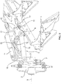
- Eine schematische Draufsicht auf einen Anbaudrehpflug in einer ersten Arbeitsstellung, in der der Schwenkbock auf eine linke Pflugseite geschwenkt ist, und
- Fig. 2:
- Eine schematische Draufsicht auf den Drehpflug ähnlich
Fig. 1 in einer zweiten, gewendeten Arbeitsstellung, in der der Wendebock auf die rechte Pflugseite geschwenkt ist.
- Fig. 1:
- A schematic plan view of a mounted reversible plow in a first working position, in which the pivot bracket is pivoted to a left plow side, and
- Fig. 2:
- A schematic plan view similar to the rotary plow
Fig. 1 in a second, reversed working position, in which the turning block is pivoted to the right plow side.
Der in den Figuren gezeigte Anbaudrehpflug 1 besitzt in an sich bekannter Weise einen Anbaubock 2, der bspw. über eine Dreipunktanlenkung mit Ober- und Unterlenkern an einem nicht gezeigten Schlepper anbaubar sein kann.The attached revolving plow 1 shown in the figures has in a conventional manner a trestle 2, for example, can be attached to a tractor, not shown, via a Dreipunktanlenkung with upper and lower links.
Der Anbaubock 2 trägt einen Pflugrahmen 3, an dem zwei Reihen von Pflugscharen 4 befestigt sind, wobei der genannte Pflugrahmen 3 zusammen mit den Pflugscharreihen um eine liegende, in Fahrtrichtung weisende Wendeachse 5 gegenüber dem Anbaubock 2 verdreht und damit gewendet werden kann, um wechselweise mit der einen Pflugscharreihe oder der anderen Pflugscharreihe pflügen zu können.The trestle 2 carries a plow frame 3, are attached to the two rows of
Um den Pflug wenden zu können, ist an dem Anbaubock 2 ein Wendebock 6 um die genannte Wendeachse 5 drehbar befestigt, wobei der Wendebock 6 mittels eines Wendeaktors 7 bspw. in Form eines Hydraulikzylinders gewendet werden kann, wobei der Wendebock 6 im Wesentlichen um 180° verdreht werden kann.In order to be able to turn the plow, a
An dem Wendebock 6 ist der Pflugrahmen 3 aufgehängt und verstellbar angelenkt, wie noch erläutert wird, wobei der insgesamt längliche, insbesondere trägerförmige Pflugrahmen 3 in seinen Arbeitsstellungen jeweils schräg, insbesondere spitzwinklig zur Wendeachse 5 geneigt angestellt ist, vgl.
Wie die Figuren zeigen, kann der Pflugrahmen 3 über ein mehrgelenkiges Anlenkgetriebe 9 an dem Wendebock 6 aufgehängt sein, wobei das Anlenkgetriebe 9 einen Anlenkträger 10 umfassen kann, der einerseits gelenkig um eine Schwenkachse parallel zur Einschwenkachse 8 an dem Wendebock 6 und andererseits gelenkig um eine Achse parallel zur Einschwenkachse 8 an dem Pflugrahmen 3 bzw. einem damit verbundenen Zwischenrahmen angelenkt sein kann. Zusammen mit dem genannten Anlenkträger 10 kann ein hiervon beabstandeter Einschwenkaktor 11 bspw. in Form eines Hydraulikzylinders ein Viergelenk bilden, über das der Pflugrahmen 3 bzw. der damit verbundene Zwischenrahmen gegenüber dem Wendebock 6 verschwenkbar ist, wenn der genannte Einschwenkaktor 11 verstellt wird.As the figures show, the plow frame 3 can be suspended on the
Wie die Figuren weiterhin zeigen, kann der Pflugrahmen 3 unabhängig von dem Einschwenkaktor 11 über weitere Gelenkigkeiten und Stellaktoren verstellt werden. Beispielsweise kann über einen Vorfurchenaktor 12 und einen Zugpunktaktor 13 die Schwenkstellung des Pflugrahmens 3 gegenüber dem genannten Zwischenrahmen 14 und/oder das zuvor genannte Viergelenk in sich weiter verstellt werden. Ein Schnittbreitenaktor 15 kann weiterhin die Schwenkstellung der Pflugschare 4 gegenüber dem Pflugrahmen 3 verstellen.As the figures further show, the plow frame 3 can be adjusted independently of the
Je nachdem, wie die weiteren Aktoren 12, 13 und 15 eingestellt sind, kann es notwendig werden, den Einschwenkaktor 11 weniger weiter oder weiter zu verstellen, um den Pflugrahmen 3 in die gewünschte Wendestellung zu verbringen. Um die jeweils gewünschte Wendestellung anzufahren, wird der genannte Einschwenkaktor 11 über eine hydraulische Drehwinkelsteuerung 16 angesteuert, wobei vorteilhafterweise kein Anschlag angefahren werden muss, sondern der Einschwenkzylinder 11 in der jeweils gewünschten Hubstellung hydraulisch gehalten werden kann, um die damit einhergehende Wendestellung des Pflugrahmens 3 zu halten.Depending on how the
Insbesondere kann in der hydraulischen Druckversorgung 17, über die der Einschwenkaktor 11 mit Hydraulikdruck versorgt werden kann, ein Sperrventil 18 vorgesehen sein, wobei das Sperrventil 18 die Zuflussseite und/oder die Abflussseite des Einschwenkaktors 11 bzw. der zugehörigen Druckmittelversorgung 17 absperren kann.In particular, in the hydraulic pressure supply 17, via which the
Das genannte Sperrventil 18 wird hierbei in Abhängigkeit der Schrägstellung des Pflugrahmens 3 gegenüber dem Wendebock 6 bezüglich der Einschwenkachse 8 angesteuert und betätigt.The said
Eine Erfassungseinrichtung 19 erfasst hierbei die Schrägstellung des Pflugrahmens 3 gegenüber dem Wendebock 6, wobei die genannte Erfassungseinrichtung 19 eine mechanische Abtastung der Schrägstellung vorsehen kann. Insbesondere kann eine mechanische Koppelung 20 zwischen dem Wendebock 6 und dem Pflugrahmen 3 vorgesehen und an das genannte Sperrventil 18 angebunden sein, um Schwenkbewegungen des Pflugrahmens 3 gegenüber dem Wendebock gegenüber der Einschwenkachse 8 in eine Ventilstellbewegung umzusetzen.In this case, a
Wie
Wie sich aus den
Die mechanische Koppel 20 ist dabei vorteilhafterweise derart konfiguriert, dass das Sperrventil 18 freigegeben bzw. geöffnet ist, solange der Pflugrahmen 3 in der gezeigten Arbeitsstellung und ähnlich schrägstehenden Winkelstellungen ausgerichtet ist, und das Sperrventil erst dann in seine absperrende Stellung gebracht wird, wenn der Pflugrahmen 3 weit genug eingeschwenkt, das heißt nahezu parallel oder nur noch geringfügig gegenüber der Wendeachse 5 schräggestellt ist. Dieser Einschwenkvorgang wird durch Ausfahren des Einschwenkaktors 11 erzielt.The
Claims (13)
Applications Claiming Priority (1)
| Application Number | Priority Date | Filing Date | Title |
|---|---|---|---|
| DE202017104155.7U DE202017104155U1 (en) | 2017-07-12 | 2017-07-12 | Mounted |
Publications (2)
| Publication Number | Publication Date |
|---|---|
| EP3427559A1 true EP3427559A1 (en) | 2019-01-16 |
| EP3427559B1 EP3427559B1 (en) | 2020-03-25 |
Family
ID=62916526
Family Applications (1)
| Application Number | Title | Priority Date | Filing Date |
|---|---|---|---|
| EP18182873.2A Active EP3427559B1 (en) | 2017-07-12 | 2018-07-11 | Mounted rotatable plough |
Country Status (2)
| Country | Link |
|---|---|
| EP (1) | EP3427559B1 (en) |
| DE (1) | DE202017104155U1 (en) |
Cited By (5)
| Publication number | Priority date | Publication date | Assignee | Title |
|---|---|---|---|---|
| DE102018115863A1 (en) * | 2018-06-29 | 2020-01-02 | Lemken Gmbh & Co. Kg | Mounted reversible plow with freewheel |
| WO2020250176A1 (en) * | 2019-06-11 | 2020-12-17 | Maschio Gaspardo S.P.A. | Mounted reversible plough |
| EP3884743A1 (en) | 2020-03-27 | 2021-09-29 | Amazonen-Werke H. Dreyer GmbH & Co. KG | Mounted reversible plough |
| IT202000009571A1 (en) | 2020-04-30 | 2021-10-30 | Maschio Gaspardo Spa | MOUNTED REVERSIBLE PLOW |
| RU2810550C2 (en) * | 2019-06-11 | 2023-12-27 | Маскио Гаспардо С.П.А. | Mounted reversible plough |
Families Citing this family (2)
| Publication number | Priority date | Publication date | Assignee | Title |
|---|---|---|---|---|
| DE102021109040A1 (en) | 2021-04-12 | 2022-10-13 | Lemken Gmbh & Co. Kg | reversible plough |
| DE102021126501A1 (en) | 2021-10-13 | 2023-04-13 | Pöttinger Landtechnik Gmbh | mounted reversible plough |
Citations (7)
| Publication number | Priority date | Publication date | Assignee | Title |
|---|---|---|---|---|
| DE7726689U1 (en) * | 1977-08-29 | 1977-12-22 | Rabewerk Heinrich Clausing, 4515 Bad Essen | ATTACHED ROTATING PLOW |
| DE8032587U1 (en) * | 1980-12-06 | 1981-05-07 | Pflugfabrik Lemken Kg, 4234 Alpen | ATTACHED PLOW WITH SWIVELING DEVICE |
| EP0045030A1 (en) * | 1980-07-24 | 1982-02-03 | Johann Gassner K.G. | Mounted reversible plough |
| DE3709696A1 (en) * | 1987-03-25 | 1988-10-06 | Joh Gassner Kg | Multi-share mounted plough |
| DE3824787A1 (en) * | 1988-07-21 | 1990-02-15 | Benno Gassner | Multi-share turn-over plough |
| DE3908985A1 (en) * | 1989-03-18 | 1990-09-27 | Integral Hydraulik Co | Hydraulic circuit for a mounted half-turn plough |
| WO2014067508A1 (en) * | 2012-10-30 | 2014-05-08 | Lemken Gmbh & Co. Kg | Mounted half-turn plough with restricted pivoting |
-
2017
- 2017-07-12 DE DE202017104155.7U patent/DE202017104155U1/en not_active Expired - Lifetime
-
2018
- 2018-07-11 EP EP18182873.2A patent/EP3427559B1/en active Active
Patent Citations (7)
| Publication number | Priority date | Publication date | Assignee | Title |
|---|---|---|---|---|
| DE7726689U1 (en) * | 1977-08-29 | 1977-12-22 | Rabewerk Heinrich Clausing, 4515 Bad Essen | ATTACHED ROTATING PLOW |
| EP0045030A1 (en) * | 1980-07-24 | 1982-02-03 | Johann Gassner K.G. | Mounted reversible plough |
| DE8032587U1 (en) * | 1980-12-06 | 1981-05-07 | Pflugfabrik Lemken Kg, 4234 Alpen | ATTACHED PLOW WITH SWIVELING DEVICE |
| DE3709696A1 (en) * | 1987-03-25 | 1988-10-06 | Joh Gassner Kg | Multi-share mounted plough |
| DE3824787A1 (en) * | 1988-07-21 | 1990-02-15 | Benno Gassner | Multi-share turn-over plough |
| DE3908985A1 (en) * | 1989-03-18 | 1990-09-27 | Integral Hydraulik Co | Hydraulic circuit for a mounted half-turn plough |
| WO2014067508A1 (en) * | 2012-10-30 | 2014-05-08 | Lemken Gmbh & Co. Kg | Mounted half-turn plough with restricted pivoting |
Cited By (10)
| Publication number | Priority date | Publication date | Assignee | Title |
|---|---|---|---|---|
| DE102018115863A1 (en) * | 2018-06-29 | 2020-01-02 | Lemken Gmbh & Co. Kg | Mounted reversible plow with freewheel |
| WO2020250176A1 (en) * | 2019-06-11 | 2020-12-17 | Maschio Gaspardo S.P.A. | Mounted reversible plough |
| CN113923972A (en) * | 2019-06-11 | 2022-01-11 | 马斯奇奥盖斯帕多股份有限公司 | Mounting type convertible farming equipment |
| CN113923972B (en) * | 2019-06-11 | 2023-08-25 | 马斯奇奥盖斯帕多股份有限公司 | Mounting type convertible tillage equipment |
| RU2810550C2 (en) * | 2019-06-11 | 2023-12-27 | Маскио Гаспардо С.П.А. | Mounted reversible plough |
| EP3884743A1 (en) | 2020-03-27 | 2021-09-29 | Amazonen-Werke H. Dreyer GmbH & Co. KG | Mounted reversible plough |
| DE102020108472A1 (en) | 2020-03-27 | 2021-09-30 | Amazonen-Werke H. Dreyer SE & Co. KG | Mounted reversible plow |
| EP3884743B1 (en) * | 2020-03-27 | 2023-08-30 | Amazonen-Werke H. Dreyer GmbH & Co. KG | Mounted reversible plough |
| IT202000009571A1 (en) | 2020-04-30 | 2021-10-30 | Maschio Gaspardo Spa | MOUNTED REVERSIBLE PLOW |
| WO2021220235A1 (en) * | 2020-04-30 | 2021-11-04 | Maschio Gaspardo S.P.A. | Mounted reversible plough |
Also Published As
| Publication number | Publication date |
|---|---|
| EP3427559B1 (en) | 2020-03-25 |
| DE202017104155U1 (en) | 2018-10-15 |
Similar Documents
| Publication | Publication Date | Title |
|---|---|---|
| EP3427559B1 (en) | Mounted rotatable plough | |
| DE102006039513B4 (en) | Reversible plow | |
| EP3166379B1 (en) | Turn plough with pivoting support wheel for mounting on the plough frame | |
| EP0628236B1 (en) | Height-adjustable device | |
| EP2914081B1 (en) | Mounted half-turn plough with restricted pivoting | |
| EP2033503B1 (en) | Semi-mounted plough | |
| EP1529431B1 (en) | Sowing machine | |
| EP1625781B1 (en) | Mounted reversible plough | |
| EP2710869A1 (en) | Implement attachment device of a work vehicle | |
| DE3028094C3 (en) | Mounted reversible plow | |
| DE19608140C1 (en) | Plough with front-furrow-width and other adjustments | |
| DE102010027264A1 (en) | Soil cultivating machine e.g. harrow sowing machine, for use with tractor, has pivoting device including angle control device that controls movement of impact element from working position to transport position in specific direction | |
| DE4306145A1 (en) | Appliance combination for the ploughing of useful agricultural areas and for ground reworking and/or ground cultivation | |
| EP1597953B1 (en) | Agricultural machine | |
| DE3232743A1 (en) | DEVICE FOR IMPROVING THE GROUND LIFE OF A TRACTOR CARRYING GROUND TILLING TOOLS | |
| DE3926381C1 (en) | Agricultural machine drive system - incorporates clutch with operating element connected to swivelling outer frame parts | |
| DE3201736C2 (en) | Reversible plow | |
| EP2974580B1 (en) | Reversible plough | |
| DE2210409C3 (en) | Semi-mounted plow | |
| DE2618892C3 (en) | Towed reversible plow for tractors driving next to the furrow | |
| AT400376B (en) | STONE AND OVERLOAD PROTECTION FOR PLOWS | |
| DE1782664C3 (en) | Plow, especially trailed or semi-mounted plow | |
| DE3414081A1 (en) | Method for operating a turnover plough provided with a jib for attaching accessories and turnover plough for carrying out the method | |
| DE1757400A1 (en) | Control device for hydraulic power lifts on towing vehicles, in particular farm tractors | |
| DE7534120U (en) | SEMI-DETACHED ROTARY PLOW WITH STEERING DEVICE |
Legal Events
| Date | Code | Title | Description |
|---|---|---|---|
| PUAI | Public reference made under article 153(3) epc to a published international application that has entered the european phase |
Free format text: ORIGINAL CODE: 0009012 |
|
| STAA | Information on the status of an ep patent application or granted ep patent |
Free format text: STATUS: THE APPLICATION HAS BEEN PUBLISHED |
|
| AK | Designated contracting states |
Kind code of ref document: A1 Designated state(s): AL AT BE BG CH CY CZ DE DK EE ES FI FR GB GR HR HU IE IS IT LI LT LU LV MC MK MT NL NO PL PT RO RS SE SI SK SM TR |
|
| AX | Request for extension of the european patent |
Extension state: BA ME |
|
| STAA | Information on the status of an ep patent application or granted ep patent |
Free format text: STATUS: REQUEST FOR EXAMINATION WAS MADE |
|
| 17P | Request for examination filed |
Effective date: 20190702 |
|
| RBV | Designated contracting states (corrected) |
Designated state(s): AL AT BE BG CH CY CZ DE DK EE ES FI FR GB GR HR HU IE IS IT LI LT LU LV MC MK MT NL NO PL PT RO RS SE SI SK SM TR |
|
| GRAP | Despatch of communication of intention to grant a patent |
Free format text: ORIGINAL CODE: EPIDOSNIGR1 |
|
| STAA | Information on the status of an ep patent application or granted ep patent |
Free format text: STATUS: GRANT OF PATENT IS INTENDED |
|
| INTG | Intention to grant announced |
Effective date: 20191028 |
|
| GRAS | Grant fee paid |
Free format text: ORIGINAL CODE: EPIDOSNIGR3 |
|
| GRAA | (expected) grant |
Free format text: ORIGINAL CODE: 0009210 |
|
| STAA | Information on the status of an ep patent application or granted ep patent |
Free format text: STATUS: THE PATENT HAS BEEN GRANTED |
|
| AK | Designated contracting states |
Kind code of ref document: B1 Designated state(s): AL AT BE BG CH CY CZ DE DK EE ES FI FR GB GR HR HU IE IS IT LI LT LU LV MC MK MT NL NO PL PT RO RS SE SI SK SM TR |
|
| REG | Reference to a national code |
Ref country code: GB Ref legal event code: FG4D Free format text: NOT ENGLISH |
|
| REG | Reference to a national code |
Ref country code: AT Ref legal event code: REF Ref document number: 1247430 Country of ref document: AT Kind code of ref document: T Effective date: 20200415 Ref country code: IE Ref legal event code: FG4D Free format text: LANGUAGE OF EP DOCUMENT: GERMAN |
|
| REG | Reference to a national code |
Ref country code: DE Ref legal event code: R096 Ref document number: 502018001022 Country of ref document: DE |
|
| PG25 | Lapsed in a contracting state [announced via postgrant information from national office to epo] |
Ref country code: FI Free format text: LAPSE BECAUSE OF FAILURE TO SUBMIT A TRANSLATION OF THE DESCRIPTION OR TO PAY THE FEE WITHIN THE PRESCRIBED TIME-LIMIT Effective date: 20200325 Ref country code: RS Free format text: LAPSE BECAUSE OF FAILURE TO SUBMIT A TRANSLATION OF THE DESCRIPTION OR TO PAY THE FEE WITHIN THE PRESCRIBED TIME-LIMIT Effective date: 20200325 |
|
| REG | Reference to a national code |
Ref country code: NO Ref legal event code: T2 Effective date: 20200325 |
|
| PG25 | Lapsed in a contracting state [announced via postgrant information from national office to epo] |
Ref country code: BG Free format text: LAPSE BECAUSE OF FAILURE TO SUBMIT A TRANSLATION OF THE DESCRIPTION OR TO PAY THE FEE WITHIN THE PRESCRIBED TIME-LIMIT Effective date: 20200625 Ref country code: HR Free format text: LAPSE BECAUSE OF FAILURE TO SUBMIT A TRANSLATION OF THE DESCRIPTION OR TO PAY THE FEE WITHIN THE PRESCRIBED TIME-LIMIT Effective date: 20200325 Ref country code: GR Free format text: LAPSE BECAUSE OF FAILURE TO SUBMIT A TRANSLATION OF THE DESCRIPTION OR TO PAY THE FEE WITHIN THE PRESCRIBED TIME-LIMIT Effective date: 20200626 Ref country code: SE Free format text: LAPSE BECAUSE OF FAILURE TO SUBMIT A TRANSLATION OF THE DESCRIPTION OR TO PAY THE FEE WITHIN THE PRESCRIBED TIME-LIMIT Effective date: 20200325 Ref country code: LV Free format text: LAPSE BECAUSE OF FAILURE TO SUBMIT A TRANSLATION OF THE DESCRIPTION OR TO PAY THE FEE WITHIN THE PRESCRIBED TIME-LIMIT Effective date: 20200325 |
|
| REG | Reference to a national code |
Ref country code: NL Ref legal event code: MP Effective date: 20200325 |
|
| REG | Reference to a national code |
Ref country code: LT Ref legal event code: MG4D |
|
| PG25 | Lapsed in a contracting state [announced via postgrant information from national office to epo] |
Ref country code: NL Free format text: LAPSE BECAUSE OF FAILURE TO SUBMIT A TRANSLATION OF THE DESCRIPTION OR TO PAY THE FEE WITHIN THE PRESCRIBED TIME-LIMIT Effective date: 20200325 |
|
| PG25 | Lapsed in a contracting state [announced via postgrant information from national office to epo] |
Ref country code: CZ Free format text: LAPSE BECAUSE OF FAILURE TO SUBMIT A TRANSLATION OF THE DESCRIPTION OR TO PAY THE FEE WITHIN THE PRESCRIBED TIME-LIMIT Effective date: 20200325 Ref country code: PT Free format text: LAPSE BECAUSE OF FAILURE TO SUBMIT A TRANSLATION OF THE DESCRIPTION OR TO PAY THE FEE WITHIN THE PRESCRIBED TIME-LIMIT Effective date: 20200818 Ref country code: LT Free format text: LAPSE BECAUSE OF FAILURE TO SUBMIT A TRANSLATION OF THE DESCRIPTION OR TO PAY THE FEE WITHIN THE PRESCRIBED TIME-LIMIT Effective date: 20200325 Ref country code: SK Free format text: LAPSE BECAUSE OF FAILURE TO SUBMIT A TRANSLATION OF THE DESCRIPTION OR TO PAY THE FEE WITHIN THE PRESCRIBED TIME-LIMIT Effective date: 20200325 Ref country code: RO Free format text: LAPSE BECAUSE OF FAILURE TO SUBMIT A TRANSLATION OF THE DESCRIPTION OR TO PAY THE FEE WITHIN THE PRESCRIBED TIME-LIMIT Effective date: 20200325 Ref country code: IS Free format text: LAPSE BECAUSE OF FAILURE TO SUBMIT A TRANSLATION OF THE DESCRIPTION OR TO PAY THE FEE WITHIN THE PRESCRIBED TIME-LIMIT Effective date: 20200725 Ref country code: EE Free format text: LAPSE BECAUSE OF FAILURE TO SUBMIT A TRANSLATION OF THE DESCRIPTION OR TO PAY THE FEE WITHIN THE PRESCRIBED TIME-LIMIT Effective date: 20200325 Ref country code: SM Free format text: LAPSE BECAUSE OF FAILURE TO SUBMIT A TRANSLATION OF THE DESCRIPTION OR TO PAY THE FEE WITHIN THE PRESCRIBED TIME-LIMIT Effective date: 20200325 |
|
| REG | Reference to a national code |
Ref country code: DE Ref legal event code: R097 Ref document number: 502018001022 Country of ref document: DE |
|
| PG25 | Lapsed in a contracting state [announced via postgrant information from national office to epo] |
Ref country code: ES Free format text: LAPSE BECAUSE OF FAILURE TO SUBMIT A TRANSLATION OF THE DESCRIPTION OR TO PAY THE FEE WITHIN THE PRESCRIBED TIME-LIMIT Effective date: 20200325 Ref country code: DK Free format text: LAPSE BECAUSE OF FAILURE TO SUBMIT A TRANSLATION OF THE DESCRIPTION OR TO PAY THE FEE WITHIN THE PRESCRIBED TIME-LIMIT Effective date: 20200325 |
|
| PLBE | No opposition filed within time limit |
Free format text: ORIGINAL CODE: 0009261 |
|
| STAA | Information on the status of an ep patent application or granted ep patent |
Free format text: STATUS: NO OPPOSITION FILED WITHIN TIME LIMIT |
|
| PG25 | Lapsed in a contracting state [announced via postgrant information from national office to epo] |
Ref country code: MC Free format text: LAPSE BECAUSE OF FAILURE TO SUBMIT A TRANSLATION OF THE DESCRIPTION OR TO PAY THE FEE WITHIN THE PRESCRIBED TIME-LIMIT Effective date: 20200325 Ref country code: PL Free format text: LAPSE BECAUSE OF FAILURE TO SUBMIT A TRANSLATION OF THE DESCRIPTION OR TO PAY THE FEE WITHIN THE PRESCRIBED TIME-LIMIT Effective date: 20200325 |
|
| 26N | No opposition filed |
Effective date: 20210112 |
|
| REG | Reference to a national code |
Ref country code: BE Ref legal event code: MM Effective date: 20200731 |
|
| PG25 | Lapsed in a contracting state [announced via postgrant information from national office to epo] |
Ref country code: LU Free format text: LAPSE BECAUSE OF NON-PAYMENT OF DUE FEES Effective date: 20200711 |
|
| PG25 | Lapsed in a contracting state [announced via postgrant information from national office to epo] |
Ref country code: SI Free format text: LAPSE BECAUSE OF FAILURE TO SUBMIT A TRANSLATION OF THE DESCRIPTION OR TO PAY THE FEE WITHIN THE PRESCRIBED TIME-LIMIT Effective date: 20200325 Ref country code: BE Free format text: LAPSE BECAUSE OF NON-PAYMENT OF DUE FEES Effective date: 20200731 |
|
| PG25 | Lapsed in a contracting state [announced via postgrant information from national office to epo] |
Ref country code: IE Free format text: LAPSE BECAUSE OF NON-PAYMENT OF DUE FEES Effective date: 20200711 |
|
| REG | Reference to a national code |
Ref country code: CH Ref legal event code: PL |
|
| PG25 | Lapsed in a contracting state [announced via postgrant information from national office to epo] |
Ref country code: LI Free format text: LAPSE BECAUSE OF NON-PAYMENT OF DUE FEES Effective date: 20210731 Ref country code: CH Free format text: LAPSE BECAUSE OF NON-PAYMENT OF DUE FEES Effective date: 20210731 |
|
| PG25 | Lapsed in a contracting state [announced via postgrant information from national office to epo] |
Ref country code: TR Free format text: LAPSE BECAUSE OF FAILURE TO SUBMIT A TRANSLATION OF THE DESCRIPTION OR TO PAY THE FEE WITHIN THE PRESCRIBED TIME-LIMIT Effective date: 20200325 Ref country code: MT Free format text: LAPSE BECAUSE OF FAILURE TO SUBMIT A TRANSLATION OF THE DESCRIPTION OR TO PAY THE FEE WITHIN THE PRESCRIBED TIME-LIMIT Effective date: 20200325 Ref country code: CY Free format text: LAPSE BECAUSE OF FAILURE TO SUBMIT A TRANSLATION OF THE DESCRIPTION OR TO PAY THE FEE WITHIN THE PRESCRIBED TIME-LIMIT Effective date: 20200325 |
|
| PG25 | Lapsed in a contracting state [announced via postgrant information from national office to epo] |
Ref country code: MK Free format text: LAPSE BECAUSE OF FAILURE TO SUBMIT A TRANSLATION OF THE DESCRIPTION OR TO PAY THE FEE WITHIN THE PRESCRIBED TIME-LIMIT Effective date: 20200325 Ref country code: AL Free format text: LAPSE BECAUSE OF FAILURE TO SUBMIT A TRANSLATION OF THE DESCRIPTION OR TO PAY THE FEE WITHIN THE PRESCRIBED TIME-LIMIT Effective date: 20200325 |
|
| GBPC | Gb: european patent ceased through non-payment of renewal fee |
Effective date: 20220711 |
|
| PG25 | Lapsed in a contracting state [announced via postgrant information from national office to epo] |
Ref country code: GB Free format text: LAPSE BECAUSE OF NON-PAYMENT OF DUE FEES Effective date: 20220711 |
|
| P01 | Opt-out of the competence of the unified patent court (upc) registered |
Effective date: 20230613 |
|
| PGFP | Annual fee paid to national office [announced via postgrant information from national office to epo] |
Ref country code: IT Payment date: 20230609 Year of fee payment: 6 |
|
| PGFP | Annual fee paid to national office [announced via postgrant information from national office to epo] |
Ref country code: NO Payment date: 20230726 Year of fee payment: 6 |
|
| PGFP | Annual fee paid to national office [announced via postgrant information from national office to epo] |
Ref country code: FR Payment date: 20230726 Year of fee payment: 6 Ref country code: DE Payment date: 20230613 Year of fee payment: 6 |