EP3427291B1 - Chamber for degassing substrates - Google Patents
Chamber for degassing substrates Download PDFInfo
- Publication number
- EP3427291B1 EP3427291B1 EP16709913.4A EP16709913A EP3427291B1 EP 3427291 B1 EP3427291 B1 EP 3427291B1 EP 16709913 A EP16709913 A EP 16709913A EP 3427291 B1 EP3427291 B1 EP 3427291B1
- Authority
- EP
- European Patent Office
- Prior art keywords
- slit
- workpiece
- pockets
- chamber
- block
- Prior art date
- Legal status (The legal status is an assumption and is not a legal conclusion. Google has not performed a legal analysis and makes no representation as to the accuracy of the status listed.)
- Active
Links
- 239000000758 substrate Substances 0.000 title claims description 26
- 238000007872 degassing Methods 0.000 title description 25
- 238000000034 method Methods 0.000 claims description 62
- 238000009489 vacuum treatment Methods 0.000 claims description 32
- 238000011068 loading method Methods 0.000 claims description 26
- 229910052751 metal Inorganic materials 0.000 claims description 13
- 239000002184 metal Substances 0.000 claims description 13
- 238000011010 flushing procedure Methods 0.000 claims description 6
- 238000004519 manufacturing process Methods 0.000 claims description 5
- 235000012431 wafers Nutrition 0.000 claims description 5
- 229910052734 helium Inorganic materials 0.000 claims description 4
- 229910052786 argon Inorganic materials 0.000 claims description 3
- 238000004891 communication Methods 0.000 claims description 3
- 238000005338 heat storage Methods 0.000 claims description 3
- 238000005086 pumping Methods 0.000 claims description 3
- 239000007789 gas Substances 0.000 description 92
- 238000001816 cooling Methods 0.000 description 24
- 238000010438 heat treatment Methods 0.000 description 20
- 238000012546 transfer Methods 0.000 description 20
- 238000012545 processing Methods 0.000 description 14
- IJGRMHOSHXDMSA-UHFFFAOYSA-N Atomic nitrogen Chemical compound N#N IJGRMHOSHXDMSA-UHFFFAOYSA-N 0.000 description 12
- 239000000463 material Substances 0.000 description 10
- 238000010943 off-gassing Methods 0.000 description 9
- 229910052757 nitrogen Inorganic materials 0.000 description 6
- 238000010926 purge Methods 0.000 description 5
- 239000000047 product Substances 0.000 description 4
- 125000006850 spacer group Chemical group 0.000 description 4
- 229910052782 aluminium Inorganic materials 0.000 description 3
- XAGFODPZIPBFFR-UHFFFAOYSA-N aluminium Chemical compound [Al] XAGFODPZIPBFFR-UHFFFAOYSA-N 0.000 description 3
- 238000011109 contamination Methods 0.000 description 3
- 230000001902 propagating effect Effects 0.000 description 3
- 238000007669 thermal treatment Methods 0.000 description 3
- XKRFYHLGVUSROY-UHFFFAOYSA-N Argon Chemical compound [Ar] XKRFYHLGVUSROY-UHFFFAOYSA-N 0.000 description 2
- 238000010276 construction Methods 0.000 description 2
- 230000008094 contradictory effect Effects 0.000 description 2
- 238000012864 cross contamination Methods 0.000 description 2
- 238000013461 design Methods 0.000 description 2
- 238000006073 displacement reaction Methods 0.000 description 2
- 239000001307 helium Substances 0.000 description 2
- SWQJXJOGLNCZEY-UHFFFAOYSA-N helium atom Chemical compound [He] SWQJXJOGLNCZEY-UHFFFAOYSA-N 0.000 description 2
- 238000012432 intermediate storage Methods 0.000 description 2
- 238000012423 maintenance Methods 0.000 description 2
- 230000003647 oxidation Effects 0.000 description 2
- 238000007254 oxidation reaction Methods 0.000 description 2
- 238000005240 physical vapour deposition Methods 0.000 description 2
- 238000007665 sagging Methods 0.000 description 2
- XLYOFNOQVPJJNP-UHFFFAOYSA-N water Substances O XLYOFNOQVPJJNP-UHFFFAOYSA-N 0.000 description 2
- TVEXGJYMHHTVKP-UHFFFAOYSA-N 6-oxabicyclo[3.2.1]oct-3-en-7-one Chemical compound C1C2C(=O)OC1C=CC2 TVEXGJYMHHTVKP-UHFFFAOYSA-N 0.000 description 1
- 229910000838 Al alloy Inorganic materials 0.000 description 1
- 239000004593 Epoxy Substances 0.000 description 1
- XUIMIQQOPSSXEZ-UHFFFAOYSA-N Silicon Chemical compound [Si] XUIMIQQOPSSXEZ-UHFFFAOYSA-N 0.000 description 1
- 229910045601 alloy Inorganic materials 0.000 description 1
- 239000000956 alloy Substances 0.000 description 1
- 239000004411 aluminium Substances 0.000 description 1
- 238000013459 approach Methods 0.000 description 1
- 239000006227 byproduct Substances 0.000 description 1
- 238000004140 cleaning Methods 0.000 description 1
- 238000009833 condensation Methods 0.000 description 1
- 230000005494 condensation Effects 0.000 description 1
- 239000004020 conductor Substances 0.000 description 1
- 230000008878 coupling Effects 0.000 description 1
- 238000010168 coupling process Methods 0.000 description 1
- 238000005859 coupling reaction Methods 0.000 description 1
- 230000001419 dependent effect Effects 0.000 description 1
- 238000000151 deposition Methods 0.000 description 1
- 230000008021 deposition Effects 0.000 description 1
- 230000002542 deteriorative effect Effects 0.000 description 1
- 238000010586 diagram Methods 0.000 description 1
- 238000009792 diffusion process Methods 0.000 description 1
- 239000000428 dust Substances 0.000 description 1
- 230000000694 effects Effects 0.000 description 1
- 238000005516 engineering process Methods 0.000 description 1
- 230000002708 enhancing effect Effects 0.000 description 1
- 238000005530 etching Methods 0.000 description 1
- 239000012530 fluid Substances 0.000 description 1
- 238000011065 in-situ storage Methods 0.000 description 1
- 238000009413 insulation Methods 0.000 description 1
- 238000002955 isolation Methods 0.000 description 1
- 239000007788 liquid Substances 0.000 description 1
- 239000011159 matrix material Substances 0.000 description 1
- 235000012054 meals Nutrition 0.000 description 1
- 238000002844 melting Methods 0.000 description 1
- 230000008018 melting Effects 0.000 description 1
- 238000012544 monitoring process Methods 0.000 description 1
- 239000002245 particle Substances 0.000 description 1
- 239000004033 plastic Substances 0.000 description 1
- 229920003023 plastic Polymers 0.000 description 1
- 229920000642 polymer Polymers 0.000 description 1
- 230000000630 rising effect Effects 0.000 description 1
- 239000004065 semiconductor Substances 0.000 description 1
- 238000000926 separation method Methods 0.000 description 1
- 229910052710 silicon Inorganic materials 0.000 description 1
- 239000010703 silicon Substances 0.000 description 1
- 229910000679 solder Inorganic materials 0.000 description 1
- 238000004544 sputter deposition Methods 0.000 description 1
- 239000000126 substance Substances 0.000 description 1
- 238000011144 upstream manufacturing Methods 0.000 description 1
Images


Classifications
-
- H—ELECTRICITY
- H01—ELECTRIC ELEMENTS
- H01L—SEMICONDUCTOR DEVICES NOT COVERED BY CLASS H10
- H01L21/00—Processes or apparatus adapted for the manufacture or treatment of semiconductor or solid state devices or of parts thereof
- H01L21/67—Apparatus specially adapted for handling semiconductor or electric solid state devices during manufacture or treatment thereof; Apparatus specially adapted for handling wafers during manufacture or treatment of semiconductor or electric solid state devices or components ; Apparatus not specifically provided for elsewhere
- H01L21/67005—Apparatus not specifically provided for elsewhere
- H01L21/67011—Apparatus for manufacture or treatment
- H01L21/67098—Apparatus for thermal treatment
- H01L21/67109—Apparatus for thermal treatment mainly by convection
-
- F—MECHANICAL ENGINEERING; LIGHTING; HEATING; WEAPONS; BLASTING
- F27—FURNACES; KILNS; OVENS; RETORTS
- F27D—DETAILS OR ACCESSORIES OF FURNACES, KILNS, OVENS, OR RETORTS, IN SO FAR AS THEY ARE OF KINDS OCCURRING IN MORE THAN ONE KIND OF FURNACE
- F27D5/00—Supports, screens, or the like for the charge within the furnace
- F27D5/0037—Supports specially adapted for semi-conductors
-
- F—MECHANICAL ENGINEERING; LIGHTING; HEATING; WEAPONS; BLASTING
- F27—FURNACES; KILNS; OVENS; RETORTS
- F27D—DETAILS OR ACCESSORIES OF FURNACES, KILNS, OVENS, OR RETORTS, IN SO FAR AS THEY ARE OF KINDS OCCURRING IN MORE THAN ONE KIND OF FURNACE
- F27D9/00—Cooling of furnaces or of charges therein
-
- H—ELECTRICITY
- H01—ELECTRIC ELEMENTS
- H01L—SEMICONDUCTOR DEVICES NOT COVERED BY CLASS H10
- H01L21/00—Processes or apparatus adapted for the manufacture or treatment of semiconductor or solid state devices or of parts thereof
- H01L21/67—Apparatus specially adapted for handling semiconductor or electric solid state devices during manufacture or treatment thereof; Apparatus specially adapted for handling wafers during manufacture or treatment of semiconductor or electric solid state devices or components ; Apparatus not specifically provided for elsewhere
- H01L21/67005—Apparatus not specifically provided for elsewhere
- H01L21/67011—Apparatus for manufacture or treatment
- H01L21/67155—Apparatus for manufacturing or treating in a plurality of work-stations
- H01L21/67161—Apparatus for manufacturing or treating in a plurality of work-stations characterized by the layout of the process chambers
- H01L21/67178—Apparatus for manufacturing or treating in a plurality of work-stations characterized by the layout of the process chambers vertical arrangement
-
- H—ELECTRICITY
- H01—ELECTRIC ELEMENTS
- H01L—SEMICONDUCTOR DEVICES NOT COVERED BY CLASS H10
- H01L21/00—Processes or apparatus adapted for the manufacture or treatment of semiconductor or solid state devices or of parts thereof
- H01L21/67—Apparatus specially adapted for handling semiconductor or electric solid state devices during manufacture or treatment thereof; Apparatus specially adapted for handling wafers during manufacture or treatment of semiconductor or electric solid state devices or components ; Apparatus not specifically provided for elsewhere
- H01L21/673—Apparatus specially adapted for handling semiconductor or electric solid state devices during manufacture or treatment thereof; Apparatus specially adapted for handling wafers during manufacture or treatment of semiconductor or electric solid state devices or components ; Apparatus not specifically provided for elsewhere using specially adapted carriers or holders; Fixing the workpieces on such carriers or holders
- H01L21/67303—Vertical boat type carrier whereby the substrates are horizontally supported, e.g. comprising rod-shaped elements
- H01L21/67309—Vertical boat type carrier whereby the substrates are horizontally supported, e.g. comprising rod-shaped elements characterized by the substrate support
-
- C—CHEMISTRY; METALLURGY
- C23—COATING METALLIC MATERIAL; COATING MATERIAL WITH METALLIC MATERIAL; CHEMICAL SURFACE TREATMENT; DIFFUSION TREATMENT OF METALLIC MATERIAL; COATING BY VACUUM EVAPORATION, BY SPUTTERING, BY ION IMPLANTATION OR BY CHEMICAL VAPOUR DEPOSITION, IN GENERAL; INHIBITING CORROSION OF METALLIC MATERIAL OR INCRUSTATION IN GENERAL
- C23C—COATING METALLIC MATERIAL; COATING MATERIAL WITH METALLIC MATERIAL; SURFACE TREATMENT OF METALLIC MATERIAL BY DIFFUSION INTO THE SURFACE, BY CHEMICAL CONVERSION OR SUBSTITUTION; COATING BY VACUUM EVAPORATION, BY SPUTTERING, BY ION IMPLANTATION OR BY CHEMICAL VAPOUR DEPOSITION, IN GENERAL
- C23C14/00—Coating by vacuum evaporation, by sputtering or by ion implantation of the coating forming material
- C23C14/58—After-treatment
- C23C14/5806—Thermal treatment
-
- F—MECHANICAL ENGINEERING; LIGHTING; HEATING; WEAPONS; BLASTING
- F27—FURNACES; KILNS; OVENS; RETORTS
- F27D—DETAILS OR ACCESSORIES OF FURNACES, KILNS, OVENS, OR RETORTS, IN SO FAR AS THEY ARE OF KINDS OCCURRING IN MORE THAN ONE KIND OF FURNACE
- F27D9/00—Cooling of furnaces or of charges therein
- F27D2009/007—Cooling of charges therein
Definitions
- Degassing means the removal of gases, especially (i) gases from evaporated liquids like water or (ii) vapors that result from sublimating materials adhering to surfaces or (iii), in vacuum technology, substances that are outgassing from (bulk) material as soon as the surrounding pressure falls below its vapor pressure.
- gases especially gases from evaporated liquids like water or (ii) vapors that result from sublimating materials adhering to surfaces or (iii), in vacuum technology, substances that are outgassing from (bulk) material as soon as the surrounding pressure falls below its vapor pressure.
- gases especially (i) gases from evaporated liquids like water or (ii) vapors that result from sublimating materials adhering to surfaces or (iii), in vacuum technology, substances that are outgassing from (bulk) material as soon as the surrounding pressure falls below its vapor pressure.
- vacuum sputter coating processes degassing is an important process step, since residual gases may result in deteriorated adhesion of deposited layers or
- sub atmospheric degassing takes place in an environment where the surrounding pressure can be lowered below atmospheric pressure.
- the workpieces are sheet-shaped, are shaped like a drum-skin in a frame, so-called Taiko's, are band or plateshaped. They all have a pair of two-dimensionally extended, parallel surfaces and a thickness D perpendicular to the addressed extended surfaces, for which there is valid: 0.01 mm ⁇ D ⁇ 5 mm .
- the workpieces may have structured or unstructured extended surfaces and may be one- or multi-layered.
- cooling down process step may be needed before further processing.
- a cooling down process step may be needed before further processing.
- the same considerations prevail as were addressed above with respect to a heating process step, thereby specifically for degassing.
- cooling down of workpieces e.g. of substrates
- a batch cooler as well acts as an intermediate storage for the workpieces.
- Some of the addressed workpieces e.g. substrates, like laminated substrates, polymer matrix substrates with embedded dies (fan-out), substrates on tape, epoxy-based substrates require extended degassing time prior to subsequent vacuum processing, like PVD.
- a degasser for highly outgassing substrates in a batch is enabling longer outgassing times without the need to sacrifice throughput in the following process sequences, which may be single substrate processes, like in a cluster tool.
- a more generalized objective is to propose a batch heat treatment chamber that is efficient and inexpensive in view of manufacturing, maintenance and operation.
- the solution according to the invention is a heater and/or cooler chamber for a batch of more than one of the addressed workpieces, having each a pair of parallel, two dimensionally extended surfaces and a thickness D of 0.01 mm ⁇ D ⁇ 5mm .
- Such chamber comprises a heat storage block, that may also be called chunk, made of a single metal part or of more than one thermally narrowly coupled metal parts.
- a heat storage block that may also be called chunk, made of a single metal part or of more than one thermally narrowly coupled metal parts.
- Such narrowly coupled metal parts behave in common thermally only negligibly different from a same one piece metal block or chunk.
- the metal may be e.g. aluminum or an alloy thereof.
- the block comprises more than one parallel slit-pockets stacked one upon the other, each dimensioned to accommodate one of the workpieces.
- Each slit-pocket extends along a slit-pocket plane E p , a geometric plane, which is a plane that cuts such slit-pocket in two parts, considered in cross section.
- the slit planes of the slit- pockets are mutually parallel.
- a slit-plane E p is shown in Fig. 1 for a slit-pocket SP in a block B.
- the geometric plane E p is shown in dash-dotted lines and being intransparent.
- Each slit-pocket has a workpiece support for a workpiece. Especially because in some embodiments gas is flown along the workpiece in the slit-pockets, such workpiece supports are realized with surfaces providing a sufficiently high sliding friction with the workpiece surface. Such workpiece supports may be realized e.g. by short studs with respective surface characteristics or e.g. by pieces of O-ring countersunk in the bottom of the slit-pockets. Each slit-pocket has at least one workpiece handling opening.
- Each slit-pocket is tailored to surround a workpiece on its workpiece support in a non-contact, closely spaced manner. This is achieved under consideration of a possible un-plane shape of the workpieces, their thickness D and possible catenary of thin workpieces in that the height h of each of the slit-pockets perpendicular to the slit-pocket planes E p is 2 . 5mm ⁇ h ⁇ 50 mm .
- This height h prevails along at least 30% of the two-dimensional extent area, in Fig. 1 marked A, of the slit-pockets, parallel to the slit-pocket plane EP. Thereby a good heat exchange from the block to the workpiece or from the workpiece to the block is achieved.
- the addressed h-range is valid for at least 50% of the addressed area.
- This height h may be valid along an area which is up to 100% of the two-dimensional extent area of the slit-pockets parallel to slit-pocket planes. Nevertheless, cutouts for access of a handling robot arm below the workpieces may be provided as will be discussed later, e.g. in such cutouts the height of the slit-pockets may possibly not fall in the addressed range, or may even not be defined if such cutouts are through-cutouts.
- each slit-pocket is operatively connected to a door arrangement which controllably frees and covers the workpiece handling opening.
- the term "covering" as used in the present description and claims addresses that the respective door arrangement may close the workpiece handling opening in a gas-tight manner or may then still establish a gas leakage from the slit-pocket volume to the surrounding of the block or may just cover the workpiece handling opening with respect to the surrounding of the chamber, e.g. spaced from the workpiece handling opening.
- At least one heater and/or cooler interface to the block is provided, e.g. a thermally highly conductive surface- area whereat heater and/or cooler-means or -fluids may be brought in tight thermal contact with the block.
- the slit-pockets wherein the workpieces are heat treated are provided within the block, e.g. machined into the block.
- the block may be built by multiple metal parts thermally narrowly coupled. Such parts may be tailored drawer-like and stacked one upon the other. These parts are thermally narrowly coupled e.g. by tightening as a staple by means of tightening screws or screw-bolts through the entire staple.
- the block is a heat storage block, i.e. acts as a heat reservoir ensuring that, once thermal equilibrium has been reached in the block, the temperature in the slit-pockets is kept substantially constant. Freeing and covering of the workpiece handling openings as well as introducing workpieces of different temperatures into the slit-pockets has negligible effect on the thermal state of the block.
- the chamber comprises a heater and/or cooler arrangement which is provided in or along at least one distinct outer area of the block, such outer area of the block forms then the heater and/or cooler interface of the block.
- a heater and/or cooler arrangement is provided in or at distinct outer areas of the block which areas face each other.
- the block of the chamber becomes in fact interposed between a pair of heater and/or cooler arrangements which, in one embodiment, are extended along the respective surfaces of the block.
- the chamber comprises a gas feed line arrangement, which dispatches in at least some of the slit-pockets or in all of the slit-pockets.
- a gas may be flown over and along the workpieces in the respective slit-pockets.
- the chamber is a heater chamber, such gas may be pre-heated so as to shorten heating-up time for the workpieces.
- the heater chamber is a degassing chamber, the addressed gas flow, as a flushing gas flow, removes gas components, resulting from workpiece outgassing, out of the slit-pocket.
- the established gas flow may be precooled to improve workpiece cooling in the slit-pockets.
- the addressed pre-heating or pre-cooling of a gas flown through the gas feed line arrangement may be realized by separate specific gas heating and/or cooling arrangements or by the same heater and/or cooler arrangement provided for respectively heating or cooling of the entire block of the chamber.
- a flushing gas stream may be established through the slit-pockets.
- the slit-pockets may further be pressurized by a gas so as to improve heat transfer from the slit-pocket to the workpiece or vice versa.
- the latter is especially exploited when the heat treatment in the block is initiated in a vacuum atmosphere, i.e. workpieces are loaded into the slit-pockets in vacuum atmosphere. Nevertheless, in one embodiment such loading is performed at ambient pressure.
- the slit-pockets, or at least some of the slit-pockets are substantially gas-tight when the door arrangement covers the workpiece handling opening.
- each of the pockets or at least some of the pockets are then still provided with a gas outlet.
- Such a gas outlet is e.g. established whenever a gas is to be flown through the slit-pockets, e.g. as a flushing gas for degassing and is to be flown along the workpiece and out of the slit-pockets during thermal treatment.
- the door arrangement it is also possible to construct the door arrangement to be able to provide covering selectively i.e. in a gas-tight manner or leaky, e.g. by a respective construction and control of the door arrangement.
- At least some or all slit-pockets are mutually aligned and stacked in a direction perpendicular to the slit-pocket planes. In one embodiment at least some or all the at least one workpiece handling openings of the slit-pockets are as well mutually aligned considered in the addressed direction. Thereby handling of the workpieces to and from the respective slit-pockets by means of handling apparatus is significantly simplified.
- At least some of or all neighboring slit-pockets are thermally substantially decoupled:
- the thermal state of a slit-pocket is substantially uninfluenced by a neighboring slit-pocket which is unloaded from a heat-treated workpiece or loaded with a yet heat-untreated workpiece.
- the slit-pockets are mutually aligned in one direction perpendicular to the slit-pocket planes and neighboring slit-pockets are separated, perpendicular to the slit-pocket planes, by sections of the block which have a thickness d, considered in the direction perpendicular to the slit-pocket planes of 0.5 mm ⁇ d ⁇ 1 0mm .
- This thickness dimensioning prevails for at least 30% or, in one embodiment, for at least 50% of the extended surface area of the slit-pockets considered parallel to the slit-pocket planes.
- the thickness d of block material sections between neighboring slit-pockets defines significantly for the thermal decoupling between neighboring slit-pockets and for the heat flow along the sections towards or from the extended surfaces of the two adjacent workpieces.
- the smaller that this thickness is selected the worse is the thermal decoupling and heat flow between neighboring slit-pockets.
- the addressed thickness of block material As it is intended to minimize mutual thermal influence between neighboring slit-pockets, one would tailor the addressed thickness of block material as large as possible. Nevertheless and as rising the thickness increases thermal inertia of the addressed section of block material, which leads to increased timespans to reach thermal equilibrium, the addressed range of d is selected to provide an appropriate heat flow, acceptable thermal inertia and thermal decoupling between neighboring slit-pockets as well as an adequate number of slit-pockets in a block of predetermined extent.
- the slit-pockets comprise in their bottom surfaces one or more than one handler cutouts which are accessible from the at least workpiece handler opening of the slit-pockets.
- handler cutouts allow introducing and removing of at least one handling arm of a workpiece handler robot so as to deposit a yet untreated workpiece on the workpiece support or to remove a treated workpiece from the workpiece support and from the slit-pocket.
- Such cutouts may even be trough-cutouts if too much not restricting heat flow and deteriorating mutual thermal decoupling of neighboring slit-pockets.
- At least some of the slit-pockets, or all of the slit-pockets, comprise one single workpiece opening.
- the door arrangement is laid out to controllably cover and free at least one of the workpiece handling openings at the same time.
- the door arrangement is laid out to controllably cover and free at least one of the workpiece handling openings at the same time.
- more than one of the workpiece handling openings may be simultaneously freed or covered.
- the door arrangement is controllable or controlled to maintain all workpiece handling openings covered during a timespan. This is necessary if e.g. all the slit-pockets are loaded with respective workpieces and heat treatment is not yet terminated for any of these workpieces.
- the door arrangement may be realized in different manner.
- distinct door-flaps or sliders may be directly mounted to the block adjacent to each of the workpiece handling openings. All of the door-flaps or sliders may be individually opened and closed by one or more than one drives. By controlling the closing-status of the flaps one may establish whether closing is performed in a gas-tight manner or so that a gas flow out of the respective slit-pocket may be established.
- At least some or all of the at least one workpiece handling openings are mutually aligned in one direction along the block.
- the door arrangement is realized by a door plate with at least one door-workpiece-handling opening, DWHO.
- the door plate is controllably slidable along and relative to the block in the addressed direction.
- the at least one DWHO is thereby brought in and out of alignment with at least one of the aligned workpiece handling openings of the slit-pockets.
- more than one DWHO may simultaneously be freed and covered if, considered in the addressed direction, the spacing between DWHOs accords with the spacing between workpiece-handling openings of the slit-pockets. Even if latter is not the case, providing more than one DWHO shortens the sliding hubs of the door-plate relative to the block to bring a respective DWHO in alignment with a workpiece-handling opening of a slit-pocket.
- the door-plate is operationally connected to a plate-drive for the relative sliding.
- the block is operationally connected to a block-drive.
- the addressed door-plate may be realized in the latter case by a wall of a casing surrounding the block.
- Such plate as e.g. the addressed wall may be distant from the surface of the block with the workpiece handling openings, leaving an interspace there between.
- the DWHO in such plate or wall is equipped with a controllably driven flap or slider.
- the block also called chunk
- the block comprises two side faces, e.g. mutually parallel faces, as well as a front face between and linking the side faces.
- the heater and/or cooler arrangements are located at or in both of the addressed side faces whereas the at least one workpiece handling openings of the slit-pockets are provided in the front face.
- the chamber comprises a gas feed line arrangement which dispatches in at least some of the slit-pockets or in all of the slit-pockets.
- the gas feed line arrangement is operationally thermally connected to a gas heater and/or gas cooler arrangement which is located along a back-face of the block, opposite the addressed front-face.
- the slit-pockets extend transvers to the addressed side-faces as e.g. perpendicularly thereto.
- heat current flows along sections of the block between neighboring slit-pockets and thus parallel to the extended surfaces of workpieces on the respective workpiece supports.
- the addressed sections provide for a good heat transport between the heater/cooler arrangements and the workpieces.
- the block is located within a thermally isolating housing and is e.g. spaced from the isolating housing.
- the isolating housing bars heat flow between the block and the surrounding of the chamber.
- the door arrangement comprises one or more than one controllable DWHO in a wall of the isolating housing and opposite to the workpiece handling openings.
- the block is operatively coupled to a controllable block drive which is constructed to bring one or more than one of the workpiece handling openings into alignment with one or more than one DWHOs.
- a controllable block drive which is constructed to bring one or more than one of the workpiece handling openings into alignment with one or more than one DWHOs.
- the workpiece handling openings are ongoingly in flow communication with an interspace between the block and the isolating housing. Thereby and especially if a flushing gas flow is established along the slit-pockets, the gas flow enters in unhindered manner the addressed interspace.
- the addressed housing comprises a pump port to remove the gas from the interspace.
- the addressed gas flow prevents ongoingly cross-contamination of the slit-pockets through their open workpiece-handling openings and may additionally lower contamination of the interspace once a DWHO in the wall of the isolating housing is opened as by a controllably driven flap or slider. A part of such gas leaves the interspace through the open DWHO.
- the chamber according to the invention comprises a gas feed line arrangement dispatching in at least some of the slit-pockets opposite to one of the at least one workpiece handling openings.
- a controlled gas flow may be established all along the extended surfaces of the workpiece on the respective workpiece support.
- the resulting pressure within the addressed slit-pocket may also be controlled by tailoring and respectively controlling the door arrangement, in analogy to providing a controlled pressure stage or valve between the inside of the slit-pocket and the surrounding.
- the chamber according to the invention which again comprises gas feed line arrangement which dispatches in at least some or in all of the slit-pockets, there is provided a gas heater and/or gas cooler arrangement for the gas in the gas feedline arrangement.
- a gas heater and/or gas cooler arrangement for the gas in the gas feedline arrangement.
- the present invention is further directed to an apparatus which comprises a chamber according to the present invention and possibly according to one or more than one of the embodiments thereof described above.
- the chamber comprises a gas feed line arrangement dispatching in at least some or in all of the slit-pockets.
- the gas feed line is operationally connected to a pressurized gas source arrangement for at least one of dried air, of N2, of Ar, of He.
- the present invention is further directed to a workpiece treatment system which comprises a chamber or apparatus according to the present invention and possibly according to one or more than one of the embodiments thereof and as was addressed, with the following limitations:
- the workpiece treatment system further comprises:
- the slit-pockets, the workpiece holders of the magazine arrangement and preferably also a workpiece holder arrangement in the load-lock arrangement are all tailored to hold the workpieces with their extended surfaces along parallel planes.
- the handling robot is tailored and controlled to handle workpieces to and from the magazine arrangement, to and from the load-lock arrangement, to and from the chamber. This handling may be realized along one common plane.
- the overall system is most flexibly adaptable to different needs and the number of magazines as well as the overall structure of the vacuum treatment arrangement may flexibly be adapted.
- the addressed robot may further be exploited to handle workpieces to and from additional stations of the system, e.g. and for specific workpieces, an alignment station, wherein the position of the workpiece is properly set.
- Such alignment station may be part of the magazine arrangement to properly align the workpieces before that they are conveyed from the magazine arrangement to the chamber.
- system comprises a workpiece aligner station as was addressed above, which is also served by the robot.
- the chamber according to the invention is tailored as a cooling chamber, than, by the addressed system and as an example, the workpieces may be conveyed by the handling robot from the magazine arrangement, possibly with an aligner, to the vacuum treatment arrangement, form the vacuum treatment arrangement to the cooling chamber and from the cooling chamber back to the magazine arrangement.
- the thermally treated workpiece is removed through the workpiece handling opening of the slit-pocket (e) .
- the timespan during which the workpiece is thermally treated might be determined in situ e.g. by monitoring the temperature course of the workpieces e.g. by an arrangement of temperature sensors, in one variant of the method according to the invention, the timespan during which the addressed thermal treatment is to be performed in the slit-pockets is predetermined.
- a cycle of the addressed steps (a) to (e) is performed multiple times in different slit-pockets with a time lag between directly subsequent ones of the addressed cycles which time lag is shorter than a timespan for the thermal treatment.
- a workpiece is conveyed between the chamber according to the invention and a magazine arrangement as well as between the addressed chamber and a vacuum treatment arrangement for vacuum treating the workpiece as well as between the vacuum treatment arrangement and the addressed magazine arrangement.
- the workpieces are conveyed from the chamber tailored as a degasser chamber to the vacuum treatment arrangement, are treated in the vacuum treatment arrangement - possibly including a cooling step - and then conveyed from the vacuum treatment arrangement to the magazine arrangement.
- the addressed conveyings may be performed directly or via an intermediate station, e.g. an alignment station may be provided ahead loading fresh workpieces to the chamber, i.e. upstream or downstream the magazine arrangement or as a part of the magazine arrangement.
- untreated workpieces are first conveyed from the magazine arrangement directly or via a further station, as e.g. an aligner station, to the vacuum treatment arrangement.
- Vacuum treated workpieces are then conveyed to the chamber according to the invention tailored as a cooler chamber and from there conveyed to the magazine arrangement.
- cooling may also be necessary after the degassing step, e.g. in the vacuum treatment arrangement or between the chamber and the vacuum treatment arrangement.
- the addressed vacuum treatment arrangement communicates to ambient via a respective I/O-load-lock arrangement which may be realized by a distinct input (I) loadlock and a distinct output (O) loadlock or by a combined input and output loadlock.
- the addressed conveyings are performed by means of single workpiece conveyings.
- the chamber comprises a number n of slit-pockets but only a smaller number m thereof is used. This allows to flexibly adapt the overall handling of the chamber to specific needs thereby optimizing on one hand conveying path lengths to and or from the addressed chamber and additionally leaving the thermal state of the chamber as unaffected as possible by respectively loading and unloading of the slit- pockets.
- the steps (a) to (e) are directly subsequently performed in non-directly neighboring slit-pockets of the chamber.
- step (a) is first performed in every second slit-pocket considered in a first direction along the chamber, then the addressed direction is inversed and the addressed step (a) is subsequently performed in every remaining slit-pocket in such inverse direction.
- every second slit-pocket is unloaded in one propagation direction, then, at the end of the stack, the propagation direction is again inversed and the remaining slit-pockets are unloaded.
- one and the same slit pocket may be unloaded and reloaded before propagating to the next slit pocket.
- the gas establishing the addressed flow along the workpiece is preheated or precooled before the addressed flow of gas along the workpieces is established.
- the addressed flow of gas is exploited as a flushing gas flow so as to remove evaporated products from the slit-pockets.
- the chamber is provided within a thermally isolating housing.
- the slit-pockets are separated from ambient atmosphere surrounding the housing via at least one controllably closable and openable DWHO of the door arrangement and in the wall of the housing.
- the block of the chamber is controllably drivingly moved in the housing by a controlled drive so as to align a workpiece handling opening of the slit-pockets and the at least one DWHO in the wall of the housing.
- the workpiece handling openings of the slit-pocket may freely communicate with the interspace between the block and the isolating housing.
- a gas flow established through the slit-pockets prevents mutual contamination of the slit-pockets by degassed products.
- the DWHO in the wall of the isolating housing in fact establishes or bars flow communication between the interspace and the surrounding of the housing.
- the one or more than one DWHOs in the wall of the isolating housing are in a good embodiment equipped with respective flaps or sliders, driven in a controlled manner.
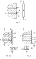
- Fig. 2 shows, most schematically and simplified, in a cross sectional representation, a part of a block 3 of a chamber 1 according to the invention.
- as shown in dashed lines at 5 of multiple metal parts, mutually biased so as to establish narrowest thermal coupling, e.g. by screws or screw bolts not shown in Fig. 2 .
- slit-pockets 7 are provided within single piece block 3 of a metal, as of aluminum or of an aluminum alloy, or of a block 3 construed .
- the slit-pockets are mutually parallel and extend along slit-pocket planes Ep.
- the slit-pocket planes Ep are parallel to the x/y plane of the coordinate system x/y/z.
- each slit-pocket 7 has workpiece-handling openings 11. Whereas, in the embodiment of Fig. 2 , each slit-pocket 7 has one single workpiece-handling opening 11, such workpiece-handling opening might additionally be provided at the end of the respective slit-pockets 7, opposite the workpiece-handling opening 11 shown.
- Fig. 3 to 5 most schematically and in a representation in analogy to that of Fig. 2 show examples of realizing the door arrangement 13 as of Fig. 2 .
- the door arrangement 13 comprises a slider (not shown) or a flap 15, pivotably or slidably (not shown) mounted to block 3.
- Each of the flaps 15 or sliders is driven by a drive unit 17, controlled as shown at control input C 17 .
- gas feed lines 19 discharge in at least some, normally in all slit-pockets 7.
- the gas feed lines 19 are operationally connected to a pressurized gas source as schematically shown at 21 of Fig. 2 .
- the flaps 15 or sliders in this embodiment, close the workpiece-handling openings 11 either in a gas-tight manner or in a leaky manner establishing a gas outlet for the gas flow F.
- a flap 15 or slider seals the workpiece-handling openings 11 in a gas-tight manner or only in a leaky manner may be set by the control of drive unit 17.
- the door arrangement 13 as of Fig. 2 is realized by a plate 23 and, as exemplified in Fig. 4a , one DWHO 25.
- the plate 23 is operationally connected to a plate drive 27, controlled at C 27 .
- the plate 23 is drivingly and controllably slid along a surface of block 3 so as to bring the DWHO 25 selectively in alignment with a workpiece-handling opening 11. Between plate 23 and block 3 a gap 28 is defined.
- Fig. 4b addresses a further embodiment.
- plate 23 with DWHO 25 is kept stationary whereas block 3 with the slit-pockets 7 is operationally connected to a block drive 29, controlled as schematically shown at C 29 .
- the block drive 29 the block 3 is slid along plate 23 to selectively bring the DWHO 25 in alignment with one of the workpiece-handling openings 11.
- the small interspace or gap 28 between the surface of block 3 and plate 23 provides for a gas flow passage from the slit-pockets 7 to the surrounding of the chamber 1.
- FIG. 5 again in a simplified and schematic representation in analogy to the representations of Figs. 3 and 4 , in fact departs from the embodiment according to Fig. 4b .It schematically shows an embodiment as practiced today.
- the plate 23 of Fig. 4b is realized by a wall 31 of an isolating housing 33 which is spaced from the surface of block 3 whereat the workpiece-handling openings 11 are provided.
- Block 3 is driven by block drive 29, controlled via C 29 , along wall 31 with the DWHO 35.
- a flap 37 or a slider is movably mounted to the wall 31 so as to close or free the DWHO 35.
- DWHO 35 and flap 37 or slider either covers the workpiece-handling openings 11 or frees such workpiece-handling openings 11 towards the surrounding atmosphere AT of the chamber 1.
- the flap 37 or slider is controllably driven by a drive 39 which is controlled as schematically shown via control input C 39 .
- the plate or wall may comprise more than one of the DWHO either to free more than one of the workpiece-handling openings 11 simultaneously or to optimize the hub which must be run by the respective plate or by the block to subsequently free workpiece-handling openings 11.
- a pumping port 41 to be operationally connected to a pump 43.
- This range of height h prevails for at least 30% or even for at least 50% of the overall surface areas of a slit-pocket 7 along the x/y plane which is parallel to slit-pocket plane Ep according to Fig. 1 .
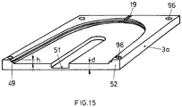
- the workpieces 50 as were addressed in the introductory part of the present description, are supported on workpiece supports 49 which, in the embodiment of Fig. 6 , are realized by pieces of O-ring material mounted along the bottom surface of the slit-pocket 7.
- the workpiece supports 49 may be constructed in a lot of different variants but it should be made sure that the surface of the workpiece supports which contact the workpieces 50 provide therewith enough friction to ensure stable support of the workpieces 50.
- the workpieces 50 have a thickness D within the range of: 0.01 mm ⁇ D ⁇ 5 mm .
- cutouts 51 may be worked in the bottom surface of the slit-pocket 7 in the bottom surface of the slit-pocket 7 so as to deposit or remove such workpiece 50.
- the sections 52 of the block 3 which separate, in z-direction, directly neighboring slit-pockets 7, are in fact significant with respect to heat flow HF there along, mutual thermal decoupling of neighboring slit-pockets 7, as well as duration for establishing a stable temperature throughout the block 3.
- these sections 52 should have a thickness d for which there is valid: 0.5 mm ⁇ d ⁇ 10 mm .
- This thickness range d shall prevail along at least 30% or even 50% of the extended surface area of the respective slit-pockets 7 along the slit-pocket plane Ep which is in Fig. 6 parallel to the x/y plane.
- the double arrow F represent the possibly established gas flow.
- Fig. 6b shows in a representation in analogy to that of Fig. 6a an embodiment in which the section 52 comprises cutouts 51, 51a including through-cutouts as shown at 51a. If the surface area covered by such through-cutouts 51a and their width is small enough they might not substantially negatively influence heat flow, mutual decoupling of directly neighboring slit-pockets 7 and dynamic thermal behavior of the entire block 3.
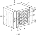
- FIG. 7 One embodiment of a batch degasser chamber 71 according to the present invention is shown in Figure 7 .
- the block of thermally well conductive metal 72 features a plurality of slit-pockets 74.
- the sections of the block located between two neighboring slit-pockets 2 are labelled 75.
- the slit-pockets 74 may be machined in a one piece block of the metal or the block 72 is, as was addressed in fig 2 at ref.nr.5, assembled from several parts thereby ensuring a thermal behavior of the resulting block 72 which is only negligibly different from a single piece meal block 72.
- the sections 75 accord with the sections 52 of Fig. 6 .
- the heating arrangements 78 are replaced by cooling arrangements with respective cooling elements, the surfaces 73 become cooler interfaces and the direction of heat flow HF is inversed.
- cutouts 78 should occupy less than 30% or less than 50% of the overall horizontal extent of slit-pocket 74.
- cutouts 78 may be only so deep that their areas contribute to that extent of slit-pocket 74 which fulfills the above mentioned range for the height h.
- the height h is accordingly adapted.
- the relation of prevailing workpiece shape and thickness and of the height h of the slit-pockets 74 is selected on one hand so as to optimize heat transfer between the top and bottom walls of the slit-pockets 74 and the workpiece, and, on the other hand, to allow a gas flow F along the extended surfaces of the workpieces 50, if such gas flow is desired.
- the prevailing shape of a workpiece 50 may be due to the workpiece having a certain sagging in the slit-pocket due to its proper weight.
- the chamber according to the invention shall be flexibly exploitable for differently tailored workpieces especially with respect to their thickness D and sagging characteristics.
- slit-pockets 7, 74 of block 3, 72 shall be mutually thermally decoupled as well as possible so that loading and removing a workpiece 50 to or from one of the slit-pockets 7, 74 does only negligibly influent the directly neighboring slit-pockets in which a workpiece 50 is heat-treated.
- the thermal intercoupling between neighboring slip-pockets 7, 74 is primarily defined by the thickness of sections 52 ( Fig. 6 ) or 75 ( Fig. 7 ) which mutually separates neighboring slit-pockets 7, 74.
- the thickness d is selected, as was already addressed, to be within the following range: 0.5 mm ⁇ d ⁇ 10 mm
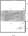
- Fig. 8 shows, simplified and schematically, an embodiment of the batch degasser chamber 1 according to the invention.
- the workpieces 50 to be heated are positioned on the workpiece supports 49, as on pins, inside the slit-pockets 74.
- Each of the slit-pockets 74 is preferably gas-supplied via a purge gas line 19 as of Fig. 2 , which may be equipped with a filter 80 to avoid particles.
- the purge gas line 19 may comprise a shallow gas cavity 81 with a length pg intended to preheat the purge- or flush-gas in the heated degasser block 72 before it enters the slit-pockets 74.
- the gas inlet is arranged preferably in the upper portion of the slit- pockets opposite the workpiece handling openings 11 since it is the goal to achieve a gas flow along the workpieces 50, especially along the top surfaces thereof, where outgassing is especially required.
- the batch degasser block 72 is positioned in a housing 86.
- This housing 86 may include an appropriate isolation 88 to avoid heat loss of the block 72.
- This concept of a fixed position of the block 72 inside the housing 86 is proposed for a workpiece loading robots with a transfer arm having a large hub or stroke of the vertical drive (z-drive).
- the maximum number of slit-pockets 74 of the degasser block 72 is then limited by the range of the vertical z-drive-stroke.
- Fig. 9a and 9b show a top view (a) and a horizontal cross section (b) through a slit-pocket 74 with a workpiece 50 placed on pins 49.
- the slit-pocket 74 is open to one side by the workpiece-handling opening 11 in order to allow loading and unloading the workpiece 50.
- On the opposite side the inner contour of the pocket is rounded to match the outer shape of a circular workpiece 50, here a wafer, and thus to enable a good heat transfer inside the block 72.
- the position of the pins 49 allows a safe operation of the workpiece 50 with the transfer arm 53.
- the inner contour of the slit-pocket 74 is just machined wide enough to take up the transfer arm 53 and the workpiece during transfer.
- a preheating gas cavity 81 can be a single straight line 83a or a network of distributed lines 83a, b, c.
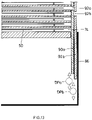
- a door plate 90 has a flat, plateshaped design of a size essentially twice the size of the front face of the block 72. It exhibits one DWHO 92 of approximately the same shape as the workpiece-handling opening 11, preferably arranged in the middle of the door plate 90 as shown in Figure 10 .
- the door plate 90 is vertically movable by the drive 27 in directions shown by arrow DP. Between the door plate 90 and the workpiece-handling opening 11 there is the gap 28. In Fig. 10 the door plate 90 is positioned with all slit-pockets 74 closed.
- FIG. 12 An alternative embodiment is shown in Figure 12 where the spacer sections 75 have such a thickness d that the DWHO 92 in the movable door plate 90 is covered by the front of the spacer sections 75 between two neighboring slit-pockets 74.
- This has advantages when operating the door plate 90 because there are many "fully closed between pockets" positions (one less than the number of slit-pockets 74).
- the drive(s) for the vertical displacement of the door plates or of the block may be arranged above or below the block and will thus not block any space where the loading and unloading operation takes place.
- the proposed chamber is preferably run at atmospheric pressure. However the basic ideas may also be applied for low pressure degassing. An effective conductive heat transfer is possible if the gas pressure is > 1kPa.
- a process sequence for a batch degasser according to the invention with n pockets may look like the following:
- a vacuum treatment arrangement 102 with a load-lock arrangement 104 separating vacuum atmosphere within the vacuum treatment arrangement from ambient atmosphere AA.
- the load-lock arrangement 104 comprises workpiece supports whereupon workpieces are supported parallel to workpieces on the respective supports in chamber 100. Workpieces in the magazine arrangement 106 as well are supported parallel to such workpieces in the load-lock arrangement 104 and chamber 100. In spite of the fact that these planes of workpiece support may be different planes, their mutual distance, vertical to such planes, is minimized up to all these planes forming a single plane.
- the chamber 100 according to Fig. 16 is realized as a degasser chamber 100 dg .
- the handling robot 108 of Fig. 16 is realized as handling robot 108' in ambient atmosphere AA and is constructed to convey single workpieces 50 to and from degasser chamber 100 dg .
- the vacuum treatment arrangement 102 of Fig. 16 is realized as a multi-station, single workpiece-treatment arrangement with a I/O load-lock 104' for workpiece input and output and a number of stations for single workpiece vacuum treatment.
- These stations may, for example, include a cooling station 111 for cooling workpieces 50 arriving from the degasser chamber 100 dg , which have to be further cooled down prior to subsequent vacuum processing.
- the processing direction for the workpieces 50 is indicated in Fig. 17 by the arrow Pr.
- the subsequent stations may further be etching stations, layer deposition stations as for PVD, reactive or nonreactive, for CVD plasma enhanced or non-plasma enhanced etc. as perfectly known to the skilled artisan.
- the magazine arrangement 106 comprises three discrete magazines and an aligner 114.
- the robot 108' conveys vacuum treated workpieces from load-lock 104' to an output-magazine and un-degassed workpieces from an input-magazine of the arrangement 106 to the degasser chamber 100 dg .
- the aligner 114 by which the addressed workpieces 50 are geometrically aligned. Because in this specific embodiment untreated workpieces are input in a magazine 106 a , then geometrically oriented in aligner 114 as addressed by the arrow (a) and are conveyed to the degasser chamber 100dg from the aligner 114 as shown by the arrow (b), it might be said that in fact the aligner 114 is part of the overall magazine arrangement 106. All the handling between all these stations and the chamber as provided in the system as shown, is performed solely by the robot 108'.
Description
- The present invention resulted from requirements in the technique of workpiece degassing. Nevertheless, these requirements also prevail in more general heat treating techniques, as of heating and cooling techniques of certain types of workpieces. Thus, focusing in the present description somewhat on degassing is not to be interpreted as limiting the scope of the present invention which is defined by the appended claims.
- Degassing means the removal of gases, especially (i) gases from evaporated liquids like water or (ii) vapors that result from sublimating materials adhering to surfaces or (iii), in vacuum technology, substances that are outgassing from (bulk) material as soon as the surrounding pressure falls below its vapor pressure. In certain vacuum treatment processes, especially vacuum sputter coating processes degassing is an important process step, since residual gases may result in deteriorated adhesion of deposited layers or unwanted by-products in the deposits.
- One differentiates between atmospheric and sub-atmospheric degassing. As the term suggests, sub atmospheric degassing takes place in an environment where the surrounding pressure can be lowered below atmospheric pressure.
- It is known that degassing can be accelerated by heating the substrates thus enhancing the outgassing rate. This method may however have its limits for certain types of materials (e.g. plastics) or where the result of previous process steps could be (negatively) affected, such as melting solder bumps, warping of substrates or increased unwanted diffusion processes. Pump capacities may be improved to more quickly remove unwanted vapors and gases. However, the physics of the outgassing process itself remains the main limiting factor. In an inline processing system with a sequence of defined process steps the degassing of a single substrate or more generically, heating of the workpieces become often the determining factor for the throughput. Heating, as e.g. for degassing, is sometimes organized in batches. In other words, a plurality of substrates is being exposed jointly to a heated environment that assists the degassing. Such a batch heater, as e.g. a batch degasser thus also acts as an intermediate storage for substrates.
- As an example from the state of the art, it is presented the following document
US 2015069043 A which discloses an anneal module for semiconductor wafers. - Consequently, there is a need for an apparatus for heating, thereby especially for degassing workpieces, as of substrates, for workpieces, as for (highly) outgassing workpieces in a batch to enable longer heat-treatment times without the need to sacrifice throughput in subsequent processes.
- The workpieces, especially addressed in the present description and claims, are sheet-shaped, are shaped like a drum-skin in a frame, so-called Taiko's, are band or plateshaped. They all have a pair of two-dimensionally extended, parallel surfaces and a thickness D perpendicular to the addressed extended surfaces, for which there is valid:

- The workpieces may have structured or unstructured extended surfaces and may be one- or multi-layered.
- In inline processing such workpieces, as e.g. substrates or wafers, there is often also a need for a cooling process step. E.g. after such workpieces have been heated up in previous processing steps, e.g. for degassing, a cooling down process step may be needed before further processing. The same considerations prevail as were addressed above with respect to a heating process step, thereby specifically for degassing. In an inline processing system with a sequence of defined process steps, cooling down of workpieces, e.g. of substrates, may as well become the determining factor for the throughput. Cooling too is sometimes organized in batches. Also for cooling a plurality of workpieces, as e.g. of substrates, they are exposed jointly to cooling down environment before being further treated or handled. Such a batch cooler as well acts as an intermediate storage for the workpieces.
- Therefore, there is also a need for an apparatus for cooling workpieces of the addressed types in a batch so as to enable longer cooling times without the need to scarify throughput of the entire process.
- Some of the addressed workpieces e.g. substrates, like laminated substrates, polymer matrix substrates with embedded dies (fan-out), substrates on tape, epoxy-based substrates require extended degassing time prior to subsequent vacuum processing, like PVD. A degasser for highly outgassing substrates in a batch is enabling longer outgassing times without the need to sacrifice throughput in the following process sequences, which may be single substrate processes, like in a cluster tool.
- Batch degassers are described e.g. in
US 6,497,734 B1 ,US 7,431,585 B2 andUS 20110114623 A1 . All these variants address a plurality of individual heater plates for each substrate. The disadvantages of stacked individual heater plates are the high costs and the required space. - It is thus, first specifically with an eye on degassing, a specific objective of the present invention to propose a batch degassing chamber that is efficient and inexpensive in terms of manufacturing, maintenance and operation.
- A more generalized objective is to propose a batch heat treatment chamber that is efficient and inexpensive in view of manufacturing, maintenance and operation.
- The solution according to the invention is a heater and/or cooler chamber for a batch of more than one of the addressed workpieces, having each a pair of parallel, two dimensionally extended surfaces and a thickness D of

- Such chamber comprises a heat storage block, that may also be called chunk, made of a single metal part or of more than one thermally narrowly coupled metal parts. Such narrowly coupled metal parts behave in common thermally only negligibly different from a same one piece metal block or chunk. The metal may be e.g. aluminum or an alloy thereof.
- The block comprises more than one parallel slit-pockets stacked one upon the other, each dimensioned to accommodate one of the workpieces. Each slit-pocket extends along a slit-pocket plane Ep, a geometric plane, which is a plane that cuts such slit-pocket in two parts, considered in cross section. The slit planes of the slit- pockets are mutually parallel. For clearness sake a slit-plane Ep is shown in
Fig. 1 for a slit-pocket SP in a block B. The geometric plane Ep is shown in dash-dotted lines and being intransparent. - Each slit-pocket has a workpiece support for a workpiece. Especially because in some embodiments gas is flown along the workpiece in the slit-pockets, such workpiece supports are realized with surfaces providing a sufficiently high sliding friction with the workpiece surface. Such workpiece supports may be realized e.g. by short studs with respective surface characteristics or e.g. by pieces of O-ring countersunk in the bottom of the slit-pockets. Each slit-pocket has at least one workpiece handling opening.
- Each slit-pocket is tailored to surround a workpiece on its workpiece support in a non-contact, closely spaced manner. This is achieved under consideration of a possible un-plane shape of the workpieces, their thickness D and possible catenary of thin workpieces in that the height h of each of the slit-pockets perpendicular to the slit-pocket planes Ep is

- This height h, shown schematically in
Fig. 1 , prevails along at least 30% of the two-dimensional extent area, inFig. 1 marked A, of the slit-pockets, parallel to the slit-pocket plane EP. Thereby a good heat exchange from the block to the workpiece or from the workpiece to the block is achieved. In one embodiment the addressed h-range is valid for at least 50% of the addressed area. - This height h may be valid along an area which is up to 100% of the two-dimensional extent area of the slit-pockets parallel to slit-pocket planes. Nevertheless, cutouts for access of a handling robot arm below the workpieces may be provided as will be discussed later, e.g. in such cutouts the height of the slit-pockets may possibly not fall in the addressed range, or may even not be defined if such cutouts are through-cutouts.
- The at least one workpiece handling opening of each slit-pocket is operatively connected to a door arrangement which controllably frees and covers the workpiece handling opening. The term "covering" as used in the present description and claims addresses that the respective door arrangement may close the workpiece handling opening in a gas-tight manner or may then still establish a gas leakage from the slit-pocket volume to the surrounding of the block or may just cover the workpiece handling opening with respect to the surrounding of the chamber, e.g. spaced from the workpiece handling opening.
- At least one heater and/or cooler interface to the block is provided, e.g. a thermally highly conductive surface- area whereat heater and/or cooler-means or -fluids may be brought in tight thermal contact with the block.
- The slit-pockets wherein the workpieces are heat treated are provided within the block, e.g. machined into the block.
- Alternatively, the block may be built by multiple metal parts thermally narrowly coupled. Such parts may be tailored drawer-like and stacked one upon the other. These parts are thermally narrowly coupled e.g. by tightening as a staple by means of tightening screws or screw-bolts through the entire staple.
- The block is a heat storage block, i.e. acts as a heat reservoir ensuring that, once thermal equilibrium has been reached in the block, the temperature in the slit-pockets is kept substantially constant. Freeing and covering of the workpiece handling openings as well as introducing workpieces of different temperatures into the slit-pockets has negligible effect on the thermal state of the block.
- In an embodiment of the chamber according to the invention the chamber comprises a heater and/or cooler arrangement which is provided in or along at least one distinct outer area of the block, such outer area of the block forms then the heater and/or cooler interface of the block.
- In an embodiment of the chamber according to the invention, a heater and/or cooler arrangement is provided in or at distinct outer areas of the block which areas face each other. Thus, the block of the chamber becomes in fact interposed between a pair of heater and/or cooler arrangements which, in one embodiment, are extended along the respective surfaces of the block.
- In an embodiment of the chamber according to the invention the chamber comprises a gas feed line arrangement, which dispatches in at least some of the slit-pockets or in all of the slit-pockets.
- Through such a gas feed line arrangement a gas may be flown over and along the workpieces in the respective slit-pockets. If the chamber is a heater chamber, such gas may be pre-heated so as to shorten heating-up time for the workpieces. If such heater chamber is a degassing chamber, the addressed gas flow, as a flushing gas flow, removes gas components, resulting from workpiece outgassing, out of the slit-pocket.
- If the chamber according to the invention is a cooler chamber, in analogy, the established gas flow may be precooled to improve workpiece cooling in the slit-pockets.
- The addressed pre-heating or pre-cooling of a gas flown through the gas feed line arrangement may be realized by separate specific gas heating and/or cooling arrangements or by the same heater and/or cooler arrangement provided for respectively heating or cooling of the entire block of the chamber.
- Thus, through such a gas feed line arrangement a flushing gas stream may be established through the slit-pockets. The slit-pockets may further be pressurized by a gas so as to improve heat transfer from the slit-pocket to the workpiece or vice versa. The latter is especially exploited when the heat treatment in the block is initiated in a vacuum atmosphere, i.e. workpieces are loaded into the slit-pockets in vacuum atmosphere. Nevertheless, in one embodiment such loading is performed at ambient pressure.
- In an embodiment of the chamber according to the invention the slit-pockets, or at least some of the slit-pockets, are substantially gas-tight when the door arrangement covers the workpiece handling opening. In one embodiment each of the pockets or at least some of the pockets are then still provided with a gas outlet.
- This is e.g. realized by a desired remaining leakage of the covering door arrangement. Such a gas outlet is e.g. established whenever a gas is to be flown through the slit-pockets, e.g. as a flushing gas for degassing and is to be flown along the workpiece and out of the slit-pockets during thermal treatment.
- It is also possible to construct the door arrangement to be able to provide covering selectively i.e. in a gas-tight manner or leaky, e.g. by a respective construction and control of the door arrangement.
- In one embodiment of the chamber according to the invention at least some or all slit-pockets are mutually aligned and stacked in a direction perpendicular to the slit-pocket planes. In one embodiment at least some or all the at least one workpiece handling openings of the slit-pockets are as well mutually aligned considered in the addressed direction. Thereby handling of the workpieces to and from the respective slit-pockets by means of handling apparatus is significantly simplified.
- Moreover, the fact that at least some or even all the at least one handling openings are aligned i.e. stapled in the addressed direction, significantly simplifies realization of the respective controllable door arrangements.
- In one embodiment of the chamber according to the invention at least some of or all neighboring slit-pockets are thermally substantially decoupled: The thermal state of a slit-pocket is substantially uninfluenced by a neighboring slit-pocket which is unloaded from a heat-treated workpiece or loaded with a yet heat-untreated workpiece.
- In one embodiment of the chamber according to the invention, the slit-pockets are mutually aligned in one direction perpendicular to the slit-pocket planes and neighboring slit-pockets are separated, perpendicular to the slit-pocket planes, by sections of the block which have a thickness d, considered in the direction perpendicular to the slit-pocket planes of

- This thickness dimensioning prevails for at least 30% or, in one embodiment, for at least 50% of the extended surface area of the slit-pockets considered parallel to the slit-pocket planes.
- The thickness d of block material sections between neighboring slit-pockets defines significantly for the thermal decoupling between neighboring slit-pockets and for the heat flow along the sections towards or from the extended surfaces of the two adjacent workpieces. The smaller that this thickness is selected, the worse is the thermal decoupling and heat flow between neighboring slit-pockets. The larger that this thickness is selected, the better is the mutual thermal decoupling of neighboring slit-pockets but the overall chamber becomes larger for a given number of slit-pockets.
- As it is intended to minimize mutual thermal influence between neighboring slit-pockets, one would tailor the addressed thickness of block material as large as possible. Nevertheless and as rising the thickness increases thermal inertia of the addressed section of block material, which leads to increased timespans to reach thermal equilibrium, the addressed range of d is selected to provide an appropriate heat flow, acceptable thermal inertia and thermal decoupling between neighboring slit-pockets as well as an adequate number of slit-pockets in a block of predetermined extent.
- In one embodiment of the chamber according to the invention the slit-pockets comprise in their bottom surfaces one or more than one handler cutouts which are accessible from the at least workpiece handler opening of the slit-pockets. Such handler cutouts allow introducing and removing of at least one handling arm of a workpiece handler robot so as to deposit a yet untreated workpiece on the workpiece support or to remove a treated workpiece from the workpiece support and from the slit-pocket. Such cutouts may even be trough-cutouts if too much not restricting heat flow and deteriorating mutual thermal decoupling of neighboring slit-pockets.
- In an embodiment of the chamber according to the invention, at least some of the slit-pockets, or all of the slit-pockets, comprise one single workpiece opening.
- Especially in the case where such openings are aligned along the block in one direction, workpiece handling is additionally simplified.
- In one embodiment of the chamber according to the invention the door arrangement is laid out to controllably cover and free at least one of the workpiece handling openings at the same time. Alternatively and even if only two slit-pockets are provided, more than one of the workpiece handling openings may be simultaneously freed or covered.
- According to one embodiment the door arrangement is controllable or controlled to maintain all workpiece handling openings covered during a timespan. This is necessary if e.g. all the slit-pockets are loaded with respective workpieces and heat treatment is not yet terminated for any of these workpieces.
- The door arrangement may be realized in different manner. E.g. distinct door-flaps or sliders may be directly mounted to the block adjacent to each of the workpiece handling openings. All of the door-flaps or sliders may be individually opened and closed by one or more than one drives. By controlling the closing-status of the flaps one may establish whether closing is performed in a gas-tight manner or so that a gas flow out of the respective slit-pocket may be established.
- In an embodiment of the chamber according to the invention at least some or all of the at least one workpiece handling openings are mutually aligned in one direction along the block. The door arrangement is realized by a door plate with at least one door-workpiece-handling opening, DWHO. The door plate is controllably slidable along and relative to the block in the addressed direction. The at least one DWHO is thereby brought in and out of alignment with at least one of the aligned workpiece handling openings of the slit-pockets.
- If more than one DWHO are provided, more than one of the aligned workpiece-handling openings of the respective slit-pockets may simultaneously be freed and covered if, considered in the addressed direction, the spacing between DWHOs accords with the spacing between workpiece-handling openings of the slit-pockets. Even if latter is not the case, providing more than one DWHO shortens the sliding hubs of the door-plate relative to the block to bring a respective DWHO in alignment with a workpiece-handling opening of a slit-pocket.
- In one embodiment the door-plate is operationally connected to a plate-drive for the relative sliding. Alternatively or additionally the block is operationally connected to a block-drive. The addressed door-plate may be realized in the latter case by a wall of a casing surrounding the block. Such plate as e.g. the addressed wall may be distant from the surface of the block with the workpiece handling openings, leaving an interspace there between. In an embodiment as practiced today the DWHO in such plate or wall is equipped with a controllably driven flap or slider.
- In the embodiments discussed until now, the block, also called chunk, may have a large variety of outer shapes.
- In one embodiment of the chamber according to the invention, the block comprises two side faces, e.g. mutually parallel faces, as well as a front face between and linking the side faces. The heater and/or cooler arrangements are located at or in both of the addressed side faces whereas the at least one workpiece handling openings of the slit-pockets are provided in the front face. Thereby separation of block areas, on one hand with the heater and/or cooler arrangement, on the other hand with the handling openings, is realized. The heat flow in the block is established perpendicularly to the direction of loading and unloading workpieces to and from the slit-pockets. This considerably simplifies the overall construction of the chamber.
- In one embodiment of the chamber according to the invention the chamber comprises a gas feed line arrangement which dispatches in at least some of the slit-pockets or in all of the slit-pockets. The gas feed line arrangement is operationally thermally connected to a gas heater and/or gas cooler arrangement which is located along a back-face of the block, opposite the addressed front-face. The slit-pockets extend transvers to the addressed side-faces as e.g. perpendicularly thereto.
- As the heater and/or cooler arrangements are provided at, i.e. along or in both of the addressed side faces and the slit-pockets extent transversely thereto e.g. perpendicularly thereto, heat current flows along sections of the block between neighboring slit-pockets and thus parallel to the extended surfaces of workpieces on the respective workpiece supports. The addressed sections provide for a good heat transport between the heater/cooler arrangements and the workpieces.
- In one embodiment of the chamber according to the invention, the block is located within a thermally isolating housing and is e.g. spaced from the isolating housing. The isolating housing bars heat flow between the block and the surrounding of the chamber.
- In one embodiment of the chamber with a thermally isolating housing, the door arrangement comprises one or more than one controllable DWHO in a wall of the isolating housing and opposite to the workpiece handling openings. The block is operatively coupled to a controllable block drive which is constructed to bring one or more than one of the workpiece handling openings into alignment with one or more than one DWHOs. Thus, if for instance two DWHOs are provided in the wall of the isolating housing, either two of the workpiece handling openings may be brought in alignment with the two DWHOs, or just one of the workpiece handling openings may selectively be brought in alignment with one DWHO thereby with an optimized minimal hub of the block. The DWHO in a wall of the isolating housing, distant from the block, are equipped with controllably driven flaps or sliders.
- In one further embodiment the workpiece handling openings are ongoingly in flow communication with an interspace between the block and the isolating housing. Thereby and especially if a flushing gas flow is established along the slit-pockets, the gas flow enters in unhindered manner the addressed interspace.
- In one further embodiment the addressed housing comprises a pump port to remove the gas from the interspace.
- If by means of a gas feedline arrangement dispatching in at least some of the slit-pockets or in all of the slit-pockets a gas flow is established through the slit-pockets, such gas flow also prevents contamination of a slit-pocket once the workpiece handling opening is freed to the surrounding by means of the door arrangement.
- In the embodiment just addressed above in which the door arrangement comprises one or more than one DWHOs in the wall of the spaced apart isolating housing, the addressed gas flow prevents ongoingly cross-contamination of the slit-pockets through their open workpiece-handling openings and may additionally lower contamination of the interspace once a DWHO in the wall of the isolating housing is opened as by a controllably driven flap or slider. A part of such gas leaves the interspace through the open DWHO.
- In one embodiment the chamber according to the invention comprises a gas feed line arrangement dispatching in at least some of the slit-pockets opposite to one of the at least one workpiece handling openings.
- By respectively establishing and controlling the door arrangement a controlled gas flow may be established all along the extended surfaces of the workpiece on the respective workpiece support. The resulting pressure within the addressed slit-pocket may also be controlled by tailoring and respectively controlling the door arrangement, in analogy to providing a controlled pressure stage or valve between the inside of the slit-pocket and the surrounding.
- In one embodiment of the chamber according to the invention which again comprises gas feed line arrangement which dispatches in at least some or in all of the slit-pockets, there is provided a gas heater and/or gas cooler arrangement for the gas in the gas feedline arrangement. Thereby, heating up or cooling down workpieces within the slit-pockets may be improved.
- Any number or all embodiments of the chamber according to the invention and as were addressed above may be combined if not mutually contradictory.
- The present invention is further directed to an apparatus which comprises a chamber according to the present invention and possibly according to one or more than one of the embodiments thereof described above. In such apparatus or system the chamber comprises a gas feed line arrangement dispatching in at least some or in all of the slit-pockets. The gas feed line is operationally connected to a pressurized gas source arrangement for at least one of dried air, of N2, of Ar, of He.
- The present invention is further directed to a workpiece treatment system which comprises a chamber or apparatus according to the present invention and possibly according to one or more than one of the embodiments thereof and as was addressed, with the following limitations:
- a) each slit-pockets in the block have a single workpiece handling opening;
- b) the slit-pockets are stacked in an aligned manner in the block and in direction perpendicular to the slit-pocket planes, thus, in most cases, in vertical direction as the slit-pockets in most cases extend along horizontal slit-pocket planes;
- c) the workpiece handling openings of the slit-pockets are aligned along the block and in the addressed direction;
- d) the door arrangement frees the inside of the slit-pockets to ambient atmosphere.
- The workpiece treatment system further comprises:
- a vacuum treatment arrangement for the workpieces which comprises a load-lock arrangement between ambient atmosphere and a vacuum atmosphere in the vacuum treatment arrangement;
- a magazine arrangement - comprising at least one magazine - in ambient atmosphere with a multitude of workpiece holders.
- The slit-pockets, the workpiece holders of the magazine arrangement and preferably also a workpiece holder arrangement in the load-lock arrangement are all tailored to hold the workpieces with their extended surfaces along parallel planes.
- The system further comprises a handling robot in ambient atmosphere which is, in one embodiment, drivingly rotatable about a vertical axis and has at least one radially extendable and retractable handling arm for at least one workpiece.
- The handling robot is tailored and controlled to handle workpieces to and from the magazine arrangement, to and from the load-lock arrangement, to and from the chamber. This handling may be realized along one common plane.
- Thereby a small footprint, compact system is realized and by means of the handling robot in ambient atmosphere, a fast and flexibly controllable inter-handling of workpieces between the addressed units is feasible. The overall system is most flexibly adaptable to different needs and the number of magazines as well as the overall structure of the vacuum treatment arrangement may flexibly be adapted. The addressed robot may further be exploited to handle workpieces to and from additional stations of the system, e.g. and for specific workpieces, an alignment station, wherein the position of the workpiece is properly set. Such alignment station may be part of the magazine arrangement to properly align the workpieces before that they are conveyed from the magazine arrangement to the chamber.
- In one embodiment of the system the handling robot is constructed to handle one single workpiece at the time to and from the magazine arrangement, to and from the loadlock arrangement and to and from the chamber.
- In a further embodiment of the system the magazine arrangement comprises more than one, e.g. two distinct magazines, e.g. one input magazine, possibly with an aligner, for workpieces yet not treated by the system, and an output magazine for workpieces having been treated by the system.
- In a further embodiment the system comprises a workpiece aligner station as was addressed above, which is also served by the robot.
- In a further embodiment the chamber is a heater chamber, thereby especially a degasser chamber, and the vacuum treatment arrangement comprises a cooler station for the workpieces. Such a cooler station might be provided alternatively between the degasser chamber and the loadlock arrangement, thus in ambient atmosphere.
- In spite of the fact that the chamber of the system may be a cooler chamber, in one embodiment of the system according to the invention, the addressed chamber is a degasser chamber. In this case workpiece handling occurs from the magazine arrangement, possibly comprising an aligner station, to the degasser chamber, from the degasser chamber to the vacuum treatment arrangement and from the vacuum treatment arrangement back to the magazine arrangement.
- If the chamber according to the invention is tailored as a cooling chamber, than, by the addressed system and as an example, the workpieces may be conveyed by the handling robot from the magazine arrangement, possibly with an aligner, to the vacuum treatment arrangement, form the vacuum treatment arrangement to the cooling chamber and from the cooling chamber back to the magazine arrangement.
- The present invention is further directed to a method of manufacturing thermally treated workpieces. The method makes use of a chamber or of an apparatus or of a system according to the invention, possibly according to one or more than one of the respective embodiments.
- The method comprises first establishing a pre-determined temperature of the block. Then:
- (a) A workpiece, as was addressed above, is loaded in at least one of the slit-pockets, and on the respective workpiece support, after having freed a respective workpiece handling opening of the respective slit-pocket by the door arrangement.
- Then (b) the respective workpiece handling opening of the slit-pocket, loaded with the workpiece, is covered by the door arrangement and the workpiece is thermally treated in the slit-pocket (c).
- Thereafter and after having freed the addressed workpiece handling opening (d) of the slit-pocket by the door arrangement, the thermally treated workpiece is removed through the workpiece handling opening of the slit-pocket (e) .
- In spite of the fact that in some applications of the method the timespan during which the workpiece is thermally treated might be determined in situ e.g. by monitoring the temperature course of the workpieces e.g. by an arrangement of temperature sensors, in one variant of the method according to the invention, the timespan during which the addressed thermal treatment is to be performed in the slit-pockets is predetermined.
- In one variant of the method according to the invention a cycle of the addressed steps (a) to (e) is performed multiple times in different slit-pockets with a time lag between directly subsequent ones of the addressed cycles which time lag is shorter than a timespan for the thermal treatment.
- This means for example that a first cycle with the steps (a) to (e) is initiated and performed in a first slit-pocket and before terminating the addresses first cycle thereby especially the thermal treating step (c) a second cycle with steps (a) to (e) is initiated at a second of the slit-pockets.
- In a further variant of the method according to the invention loading workpieces into the slit-pocket is performed departing from ambient atmosphere and removing a thermally treated workpiece from the slit-pockets is performed into ambient atmosphere.
- In one variant of the method according to the invention a workpiece is conveyed between the chamber according to the invention and a magazine arrangement as well as between the addressed chamber and a vacuum treatment arrangement for vacuum treating the workpiece as well as between the vacuum treatment arrangement and the addressed magazine arrangement. Thus, if a vacuum treatment for the workpiece necessitates degassed workpieces, the workpieces are conveyed from the chamber tailored as a degasser chamber to the vacuum treatment arrangement, are treated in the vacuum treatment arrangement - possibly including a cooling step - and then conveyed from the vacuum treatment arrangement to the magazine arrangement. Thereby the addressed conveyings may be performed directly or via an intermediate station, e.g. an alignment station may be provided ahead loading fresh workpieces to the chamber, i.e. upstream or downstream the magazine arrangement or as a part of the magazine arrangement.
- If, for instance, after vacuum treatment of the workpieces the workpieces have to be cooled down, then and as a further example, untreated workpieces are first conveyed from the magazine arrangement directly or via a further station, as e.g. an aligner station, to the vacuum treatment arrangement. Vacuum treated workpieces are then conveyed to the chamber according to the invention tailored as a cooler chamber and from there conveyed to the magazine arrangement. As was addressed above, cooling may also be necessary after the degassing step, e.g. in the vacuum treatment arrangement or between the chamber and the vacuum treatment arrangement.
- Further and if according to one embodiment of the invention loading the chamber with workpieces is performed from ambient atmosphere and unloading workpieces from the chamber as well occurs into ambient atmosphere, the addressed vacuum treatment arrangement communicates to ambient via a respective I/O-load-lock arrangement which may be realized by a distinct input (I) loadlock and a distinct output (O) loadlock or by a combined input and output loadlock.
- In a further variant of the just addressed variant of the method according to the invention, the addressed conveyings are performed by means of single workpiece conveyings.
- According to a variant of the method according to the invention, the chamber comprises a number n of slit-pockets but only a smaller number m thereof is used. This allows to flexibly adapt the overall handling of the chamber to specific needs thereby optimizing on one hand conveying path lengths to and or from the addressed chamber and additionally leaving the thermal state of the chamber as unaffected as possible by respectively loading and unloading of the slit- pockets.
- Thereby, in one variant of the just addressed variant, directly subsequent loading of workpieces in the slit-pockets is performed at time intervals dT and each workpiece rests in the chamber during a predetermined time span Δ. The quotient of Δ/dT is rounded to an integer (Δ/dT)I and there is valid m = (Δ/dT)I . Due to this appropriate selection of the number m of used slit-pockets, whenever the last slit-pocket is loaded, the heat treatment of the workpiece in the first loaded slit-pocket is terminated and thus the respective workpiece may be removed from the first loaded slit-pocket. After dT the treatment of the workpiece loaded in second instance is terminated etc. Thus one slit-pocket after the other may cyclically be unloaded and reloaded.
- In one embodiment of the method according to the invention the steps (a) to (e) are directly subsequently performed in non-directly neighboring slit-pockets of the chamber. Thereby one achieves that the thermal disturbances upon a neighboring slit-pocket, which is in treatment status, is minimized.
- In a further variant of the method according to the invention in which the slit-pockets are stacked one on the other, step (a) is first performed in every second slit-pocket considered in a first direction along the chamber, then the addressed direction is inversed and the addressed step (a) is subsequently performed in every remaining slit-pocket in such inverse direction.
- Thus, as an example, first every second slit-pocket is loaded in one propagating direction along the stack of slit-pockets, then propagation direction is inversed and the remaining slit-pockets are loaded.
- In analogy, every second slit-pocket is unloaded in one propagation direction, then, at the end of the stack, the propagation direction is again inversed and the remaining slit-pockets are unloaded.
- Thereby one and the same slit pocket may be unloaded and reloaded before propagating to the next slit pocket.
- Although it is possible, according to the method of the present invention, to load and remove a workpiece through different workpiece handling openings of one slit-pocket, in one variant of the method according to the invention loading a workpiece to and removing a workpiece from the slit-pocket is performed through the same workpiece handling opening of the slit-pocket.
- It is absolutely possible according to the method of the invention to load and/or remove simultaneously more than one workpiece to respectively more than one of the slit-pockets. In one variant of the method according to the invention, only one single workpiece is loaded to and/or removed from a slit-pocket at a time, i.e. simultaneously.
- In one variant of the method according to the invention at least during the step of thermally treating there is established a flow of a gas along the workpiece and out of the respective slit-pocket.
- In a variant of the method according to the invention, the gas establishing the addressed flow along the workpiece is preheated or precooled before the addressed flow of gas along the workpieces is established.
- If the chamber according to the invention and in the addressed method is exploited as a degasser chamber, the addressed flow of gas is exploited as a flushing gas flow so as to remove evaporated products from the slit-pockets.
- In a further variant of the method according the invention the chamber is provided within a thermally isolating housing. By such thermally isolating housing heat exchange between the block of the chamber and a surrounding of the chamber is minimized.
- In a further variant of the method wherein the block of the chamber is provided within a thermally isolating housing at least during thermally treating a workpiece in the slit-pockets a flow of gas is established along the workpieces and out of the slit-pockets into an interspace between the isolating housing and the block and the addressed gas is removed from the interspace preferably by pumping.
- In a further embodiment of the method according to the invention the slit-pockets are separated from ambient atmosphere surrounding the housing via at least one controllably closable and openable DWHO of the door arrangement and in the wall of the housing. The block of the chamber is controllably drivingly moved in the housing by a controlled drive so as to align a workpiece handling opening of the slit-pockets and the at least one DWHO in the wall of the housing.
- Thereby the workpiece handling openings of the slit-pocket may freely communicate with the interspace between the block and the isolating housing. A gas flow established through the slit-pockets prevents mutual contamination of the slit-pockets by degassed products. The DWHO in the wall of the isolating housing in fact establishes or bars flow communication between the interspace and the surrounding of the housing. The one or more than one DWHOs in the wall of the isolating housing are in a good embodiment equipped with respective flaps or sliders, driven in a controlled manner.
- Depending on the respective application it might be desirable to establish in the interspace and with respect to the surrounding atmosphere an overpressure so that even when the DWHO is open, no gas flow is established from the surrounding towards the interspace. Alternatively it might be desired to establish in the interspace a slight underpressure with respect to the pressure in the surrounding of the housing so as to prevent a gas flow from the interspace to the surrounding when the addressed DWHO is open. Latter may be advisable if, for instance, degassed products conveyed by the gas flows into the interspace are harmful and should not be freed in the surrounding atmosphere which is, in a today practiced variant, ambient atmosphere.
- In a further variant of the method according to the invention at least loading of the workpiece is performed in vacuum at a first pressure and the respective slit-pocket loaded with the workpiece is pressurized, during treating the workpiece, to a second pressure which is higher than the first pressure. Thereby heat transfer to or from the workpiece in vacuum is improved.
- Any number of all variants of the method according to the invention as addressed above may be combined if not mutually contradictory.
- The invention and different aspects thereof shall now further be exemplified with the help of figures.
- The Figures show:
-
Fig. 1 schematically and in a perspective view a block of a chamber according to the present invention, shown most generically, with a slit-pocket, to explain the definition of the term "slit-pocket plane"; -
Fig. 2 still in a schematic, simplified representation a cross-section through a block of the chamber according to the invention along the slit-pockets. -
Fig. 3 in a representation in analogy to that ofFig. 2 , a first embodiment of realizing a door arrangement as used in the chamber according to the present invention. -
Fig. 4a in a representation in analogy to that ofFig. 3 a further embodiment of realizing the door arrangement. -
Fig. 4b still in a representation in analogy to the representations of theFigs. 3 or 4a a further embodiment of realizing the door arrangement. -
Fig. 5 still in a representation in analogy to that of theFigs. 3 and 4a, 4b a further, today practiced embodiment of the door arrangement and as provided in the chamber according to the invention. -
Fig. 6a a simplified cross-sectional view along the dash-dotted lines A-A inFig. 2 and through a part of a slit-pocket. -
Fig. 6b in a representation in analogy to that ofFig. 6a a further embodiment of possibly structuring the bottom section of a slit-pocket in the chamber according the present invention. -
Fig. 7 in perspective view still schematically and simplified an embodiment of the chamber according to the invention. - In
Fig. 8 shows schematically and simplified a cross-section through an embodiment of a chamber according to the invention with an isolating housing surrounding the block of the chamber. -
Fig. 9a shows a top-view on a slit-pocket of an embodiment of the chamber according to the invention with a transfer arm of the handling robot. -
Fig. 9b shows a cross-section through the slit-pocket as ofFig. 9a . -
Fig. 10 shows schematically and simplified a cross-section through an embodiment of the chamber according to the invention, the door arrangement comprising a door plate with a door-workpiece-handling opening - DWHO - in closed or covering position. -
Fig. 11 shows in a representation in analogy to that ofFig. 10 the cross-section through an embodiment of the chamber according to the invention and according to the embodiment ofFig. 10 whereby the door plate frees the lowest slit-pocket (left-hand representation) and the uppermost slit-pocket (right-.hand representation). -
Fig. 12 shows in a representation in analogy to those ofFigs. 10 and11 a cross-section through an embodiment of the chamber according to the invention, the door plate of the door arrangement covering all workpiece-handling openings of the slit-pockets in a position where the DWHO is in an intermediate position between two neighboring slit-pockets. -
Fig. 13 shows in a representation in analogy to those of theFigs. 10 to 12 a part of an embodiment of a chamber according to the invention wherein the door arrangement is implemented by two independently driven door plates. -
Fig. 14 shows in a representation in analogy to those of theFigs. 10 to 13 a cross-section through an embodiment of the chamber according to the invention wherein the door arrangement is operated by a driven block and wherein the block is shown in two different positions. -
Fig. 15 shows in a perspective view an embodiment of the bottom section of a slit-pocket of a chamber according to the invention. -
Fig. 16 shows a block-diagram representation of a system according to the invention making use of a chamber according to the invention. -
Fig. 17 shows in a schematic and simplified representation one embodiment of the system according toFig. 16 . -
Fig. 18 shows a representation of occupation-times of the slit-pockets by workpieces at a slit-pocket staple. - The invention will now be further exemplified, somehow focused on degassing, with the help of figures.
-
Fig. 2 shows, most schematically and simplified, in a cross sectional representation, a part of ablock 3 of achamber 1 according to the invention. Withinsingle piece block 3 of a metal, as of aluminum or of an aluminum alloy, or of ablock 3 construed ,as shown in dashed lines at 5, of multiple metal parts, mutually biased so as to establish narrowest thermal coupling, e.g. by screws or screw bolts not shown inFig. 2 , slit-pockets 7 are provided. The slit-pockets are mutually parallel and extend along slit-pocket planes Ep. In the representation according toFig. 2 the slit-pocket planes Ep are parallel to the x/y plane of the coordinate system x/y/z. The slit-pockets 7 are stacked one upon the other whereby they are not necessarily aligned in y direction. The slit-pockets 7 comprise, as schematically shown, workpiece supports 9 for the workpieces as addressed above, which are not shown inFig. 2 . - The slit-
pockets 7 have workpiece-handlingopenings 11. Whereas, in the embodiment ofFig. 2 , each slit-pocket 7 has one single workpiece-handlingopening 11, such workpiece-handling opening might additionally be provided at the end of the respective slit-pockets 7, opposite the workpiece-handlingopening 11 shown. - The
chamber 1 further comprises adoor arrangement 13, schematically shown inFig. 2 , for freeing or covering selectively workpiece-handlingopenings 11 of the slit-pockets 7. As schematically shown inFig. 2 by control input C13 to thedoor arrangement 13, thedoor arrangement 13 is controllable with respect to the freeing/covering status of workpiece-handlingopenings 11. -
Fig. 3 to 5 most schematically and in a representation in analogy to that ofFig. 2 show examples of realizing thedoor arrangement 13 as ofFig. 2 . - According to
Fig. 3 thedoor arrangement 13 comprises a slider (not shown) or aflap 15, pivotably or slidably (not shown) mounted to block 3. Each of theflaps 15 or sliders is driven by adrive unit 17, controlled as shown at control input C17. - As shown in
Fig. 2 in dashed lines and especially if thechamber 1 is a degasser chamber,gas feed lines 19 discharge in at least some, normally in all slit-pockets 7. Thegas feed lines 19 are operationally connected to a pressurized gas source as schematically shown at 21 ofFig. 2 . - Back to the embodiment of
Fig. 3 and with an eye on establishing a gas flow F along and through the slit-pockets 7 by thegas feed lines 19, especially in an embodiment wherein thechamber 1 is a degasser chamber, theflaps 15 or sliders, in this embodiment, close the workpiece-handlingopenings 11 either in a gas-tight manner or in a leaky manner establishing a gas outlet for the gas flow F. Whether aflap 15 or slider seals the workpiece-handlingopenings 11 in a gas-tight manner or only in a leaky manner may be set by the control ofdrive unit 17. - According to
Fig. 4a , thedoor arrangement 13 as ofFig. 2 is realized by aplate 23 and, as exemplified inFig. 4a , oneDWHO 25. In the example according toFig. 4a , theplate 23 is operationally connected to aplate drive 27, controlled at C27. The plate 23 is drivingly and controllably slid along a surface ofblock 3 so as to bring the DWHO 25 selectively in alignment with a workpiece-handlingopening 11. Betweenplate 23 and block 3 agap 28 is defined. - With an eye on an established the gas flow F, there is ongoingly provided a gas outlet between
plate 23 and the surface ofblock 3 through thegap 28. - Departing from the representation of
Fig. 4a, Fig. 4b addresses a further embodiment. In this embodiment and as shown also inFig. 4a by the symbol S,plate 23 withDWHO 25 is kept stationary whereasblock 3 with the slit-pockets 7 is operationally connected to ablock drive 29, controlled as schematically shown at C29. By means of theblock drive 29 theblock 3 is slid alongplate 23 to selectively bring the DWHO 25 in alignment with one of the workpiece-handlingopenings 11. Here too, the small interspace orgap 28 between the surface ofblock 3 andplate 23 provides for a gas flow passage from the slit-pockets 7 to the surrounding of thechamber 1. - The embodiment according to
Fig. 5 , again in a simplified and schematic representation in analogy to the representations ofFigs. 3 and 4 , in fact departs from the embodiment according toFig. 4b .It schematically shows an embodiment as practiced today. Theplate 23 ofFig. 4b is realized by awall 31 of an isolatinghousing 33 which is spaced from the surface ofblock 3 whereat the workpiece-handlingopenings 11 are provided.Block 3 is driven byblock drive 29, controlled via C29, alongwall 31 with theDWHO 35. Aflap 37 or a slider is movably mounted to thewall 31 so as to close or free theDWHO 35. Thus the door arrangement ofwall 31,DWHO 35 andflap 37 or slider either covers the workpiece-handlingopenings 11 or frees such workpiece-handlingopenings 11 towards the surrounding atmosphere AT of thechamber 1. This wheneverblock 3 is driven in a position in which a respective workpiece-handlingopening 11 is aligned with theDWHO 35 and theflap 37 or slider is opened. Theflap 37 or slider is controllably driven by adrive 39 which is controlled as schematically shown via control input C39. - In all embodiments according to
Figs. 4 and5 the plate or wall may comprise more than one of the DWHO either to free more than one of the workpiece-handlingopenings 11 simultaneously or to optimize the hub which must be run by the respective plate or by the block to subsequently free workpiece-handlingopenings 11. - With an eye on
Fig. 5 and combined with the embodiment in which a gas flow F according toFig. 2 , e.g. as a degassing flush, is established, the following prevails:
The gas flow F freely exits from the slit-pockets 7 into the interspace I between thewall 31 and the surface ofblock 3. This prevents cross-contamination of the slit-pockets 7. If such gas flow provides in interspace I a high enough pressure with respect to the pressure in the surrounding AT, it might even be possible to omit aflap 37 or slider. - In one embodiment, as practiced today, there is provided, in the wall of
housing 33, a pumpingport 41 to be operationally connected to apump 43. - In the interspace I a pressure may be established which is slightly higher than the pressure in the surrounding AT, which is in practice mostly ambient pressure, so as to establish a gas flow from the interspace I to the surrounding AT whenever the
flap 37 or slider frees theDWHO 35. Nevertheless and if the degassed products are harmful and should not be dispatched into the surrounding AT, then the pressure in the interspace I may be selected and controlled to be slightly lower than the pressure in the surrounding AT so as to establish a gas flow from the surrounding AT into the interspace I whenever theflap 37 or slider is open. The gas which is flown through the slit-pockets 7 frompressurized gas source 21 ofFig. 2 may be dried air if the respective workpiece to be treaded is uncritical which respect to oxidation, otherwise at least one of N2, Ar, He. -
Fig. 6 shows schematically and simplified a part of a cross-section according to line A-A ofFig. 2 through a part ofblock 3. The coordinate system as introduced inFig. 2 is also shown inFig. 6 . Each of the slit-pockets has a height h for which there is valid:
- This range of height h prevails for at least 30% or even for at least 50% of the overall surface areas of a slit-
pocket 7 along the x/y plane which is parallel to slit-pocket plane Ep according toFig. 1 . In the slit-pockets 7 theworkpieces 50 as were addressed in the introductory part of the present description, are supported on workpiece supports 49 which, in the embodiment ofFig. 6 , are realized by pieces of O-ring material mounted along the bottom surface of the slit-pocket 7. Thereby the workpiece supports 49 may be constructed in a lot of different variants but it should be made sure that the surface of the workpiece supports which contact theworkpieces 50 provide therewith enough friction to ensure stable support of theworkpieces 50. Theworkpieces 50 have a thickness D within the range of:
- In the bottom surface of the slit-
pocket 7 one or more than onecutouts 51 may be worked.Such cutouts 51 may be necessary to allow anarm 53 of a handler, as shown in dashed lines, to enter the slit-pockets 7 beneath the support surfaces of the workpiece supports 49 so as to deposit or removesuch workpiece 50. - The
sections 52 of theblock 3 which separate, in z-direction, directly neighboring slit-pockets 7, are in fact significant with respect to heat flow HF there along, mutual thermal decoupling of neighboring slit-pockets 7, as well as duration for establishing a stable temperature throughout theblock 3. - It has been recognized that these
sections 52 should have a thickness d for which there is valid:
- This thickness range d shall prevail along at least 30% or even 50% of the extended surface area of the respective slit-
pockets 7 along the slit-pocket plane Ep which is inFig. 6 parallel to the x/y plane. - If the cutouts fulfill the addressed range for thickness d, they do contribute to the addressed at least 30% of the extent of the slit-pocket surface area to be considered.
- The double-arrow I/O schematically represent the movement of the
robot arm 53 into and out of slit-pockets 7. - The double arrow F represent the possibly established gas flow.
-
Fig. 6b shows in a representation in analogy to that ofFig. 6a an embodiment in which thesection 52 comprisescutouts cutouts 51a and their width is small enough they might not substantially negatively influence heat flow, mutual decoupling of directly neighboring slit-pockets 7 and dynamic thermal behavior of theentire block 3. - One embodiment of a
batch degasser chamber 71 according to the present invention is shown inFigure 7 . The block of thermally wellconductive metal 72 features a plurality of slit-pockets 74. The sections of the block located between two neighboring slit-pockets 2 are labelled 75. The slit-pockets 74 may be machined in a one piece block of the metal or theblock 72 is, as was addressed infig 2 at ref.nr.5, assembled from several parts thereby ensuring a thermal behavior of the resultingblock 72 which is only negligibly different from a singlepiece meal block 72. Thesections 75 accord with thesections 52 ofFig. 6 . - The
block 72 is heated byheater elements 76 ofheating arrangements 78 on thesidewalls 73 of theblock 72. By using the side-walls 73 ofblock 72 and leaving empty top and bottom faces thereof, a homogeneous temperature profile along all the slit-pockets 74 is achieved. - The
heating arrangements 78 with therespective heater elements 76 are biased, as by a multitude of screws (not shown) to the side faces or surfaces 73 ofblock 72. The arrows HF schematically indicate the heat flow from theheating arrangements 78 throughblock 72. The lateral or side surfaces 73 ofblock 72 form, in this embodiment, a heater interface to block 72. - If the addressed chamber with
block 72 is tailored as a cooler chamber then theheating arrangements 78 are replaced by cooling arrangements with respective cooling elements, thesurfaces 73 become cooler interfaces and the direction of heat flow HF is inversed. - As was already discussed in context with
Fig. 6 also in this embodiment of the chamber withblock 72, the bottom surfaces of the slit-pockets 74 comprise acentral handler cutout 78 for introducing and removing a handling arm, 53 inFig. 6 , beneath the workpiece to be loaded or removed from the respective slit-pockets 74. - Again, if the height h of the slit-
pocket 74 with respect to the bottom of thecutouts 78 exceeds the range described in context withFig. 6a ,such cutouts 78 should occupy less than 30% or less than 50% of the overall horizontal extent of slit-pocket 74. Clearly,such cutouts 78 may be only so deep that their areas contribute to that extent of slit-pocket 74 which fulfills the above mentioned range for the height h. - Dependent from the prevailing shape and thickness D of the
workpiece 50, the height h is accordingly adapted. - The relation of prevailing workpiece shape and thickness and of the height h of the slit-
pockets 74 is selected on one hand so as to optimize heat transfer between the top and bottom walls of the slit-pockets 74 and the workpiece, and, on the other hand, to allow a gas flow F along the extended surfaces of theworkpieces 50, if such gas flow is desired. One should consider that the prevailing shape of a workpiece 50 (not shown inFig. 7 ) may be due to the workpiece having a certain sagging in the slit-pocket due to its proper weight. - The chamber according to the invention shall be flexibly exploitable for differently tailored workpieces especially with respect to their thickness D and sagging characteristics.
- As was addressed, slit-
pockets block workpiece 50 to or from one of the slit-pockets workpiece 50 is heat-treated. The thermal intercoupling between neighboring slip-pockets Fig. 6 ) or 75 (Fig. 7 ) which mutually separates neighboring slit-pockets - In view of the trend off for dimensioning of the
section pockets pockets block 
-
Fig. 8 shows, simplified and schematically, an embodiment of thebatch degasser chamber 1 according to the invention. Theworkpieces 50 to be heated are positioned on the workpiece supports 49, as on pins, inside the slit-pockets 74. Each of the slit-pockets 74 is preferably gas-supplied via apurge gas line 19 as ofFig. 2 , which may be equipped with afilter 80 to avoid particles. Thepurge gas line 19 may comprise ashallow gas cavity 81 with a length pg intended to preheat the purge- or flush-gas in theheated degasser block 72 before it enters the slit-pockets 74. The gas inlet is arranged preferably in the upper portion of the slit- pockets opposite theworkpiece handling openings 11 since it is the goal to achieve a gas flow along theworkpieces 50, especially along the top surfaces thereof, where outgassing is especially required. - The
batch degasser block 72 is positioned in ahousing 86. Thishousing 86 may include anappropriate isolation 88 to avoid heat loss of theblock 72. This concept of a fixed position of theblock 72 inside thehousing 86 is proposed for a workpiece loading robots with a transfer arm having a large hub or stroke of the vertical drive (z-drive). The maximum number of slit-pockets 74 of thedegasser block 72 is then limited by the range of the vertical z-drive-stroke. -
Fig. 9a and 9b show a top view (a) and a horizontal cross section (b) through a slit-pocket 74 with aworkpiece 50 placed onpins 49. The slit-pocket 74 is open to one side by the workpiece-handlingopening 11 in order to allow loading and unloading theworkpiece 50. On the opposite side the inner contour of the pocket is rounded to match the outer shape of acircular workpiece 50, here a wafer, and thus to enable a good heat transfer inside theblock 72. The position of thepins 49 allows a safe operation of theworkpiece 50 with thetransfer arm 53. The inner contour of the slit-pocket 74 is just machined wide enough to take up thetransfer arm 53 and the workpiece during transfer. Consequently the slit- pocket - 74 - volume is minimized and the spacer section - 75 - profile is maximized so that the best possible heat transfer is supported. Thepurge gas line 19 is arranged opposite to the workpiece-handlingopening 11. A preheatinggas cavity 81 can be a singlestraight line 83a or a network of distributedlines 83a, b, c. - The embodiment of
Fig. 10 , shown in a representation analogue to that ofFig. 8 , accords principally with the embodiment ofFig. 4a . Adoor plate 90 has a flat, plateshaped design of a size essentially twice the size of the front face of theblock 72. It exhibits oneDWHO 92 of approximately the same shape as the workpiece-handlingopening 11, preferably arranged in the middle of thedoor plate 90 as shown inFigure 10 . Thedoor plate 90 is vertically movable by thedrive 27 in directions shown by arrow DP. Between thedoor plate 90 and the workpiece-handlingopening 11 there is thegap 28. InFig. 10 thedoor plate 90 is positioned with all slit-pockets 74 closed. -
Figure 11 shows thedoor plate 90 being positioned to load or unload a workpiece in the lowest slit-pocket 74l (left) and in the uppermost slit-pocket 74u (right). Thedoor plate 90 allows to keep all slit-pockets 74 closed during a load/unload operation with the exception of the slit-pocket 74 to be accessed. The position can be determined either by means of a sensor or markings or electronically with the aid of a stepper motor as the driven 27. - An alternative embodiment is shown in
Figure 12 where thespacer sections 75 have such a thickness d that theDWHO 92 in themovable door plate 90 is covered by the front of thespacer sections 75 between two neighboring slit-pockets 74. This has advantages when operating thedoor plate 90 because there are many "fully closed between pockets" positions (one less than the number of slit-pockets 74). There is however the disadvantage that at a given maximum height of the degasser stackless workpieces 50 can be processed than in the version described above. -
Figure 13 shows another alternative embodiment with twodoor plates DWHO 92a, 92b are offset just so much to have a "closed" configuration. A throughopening DWHO can be quickly realized by aligning bothopenings 92a, 92b. This solution will allow for better thermal insulation while still allowing a compact arrangement of slit-pockets 74. - For all those embodiments the load operation will comprise:
- Determining an empty slit-pocket inside the degasser block. This can be realized either by a sensor giving a respective (occupied/free) signal or by an electronic controller supervising the status of the slit-pockets. Such a controller could also transmit an "all pockets full" signal to the Load/Unload handling system.
- Giving access to a free slit-pocket by aligning a DWHO with the respective workpiece-handling opening in the block.
- Placing a workpiece on a handler capable of performing a z-motion (i.e. vertically in embodiments according to Fig's 10 to 12) and aligning the handler with the DWHO.
- Introducing the workpiece through the DWHO into the slit-
pocket 74. - Placing the workpiece on the workpiece supports.
- Retracting the handler from the slit-pocket.
- Covering the workpiece handling opening of the slit-pocket by the respective door plate. Especially if a
transfer arm 53 with a vertical z-drive is not available, an alternative solution - as today practiced - is to vertically move
whole block 72 inside thehousing 86 by ablock drive 29 as shown inFig. 14 ). This embodiment principally accords with the embodiment ofFig. 4b orFig. 5 . In this case there is at least one DWHO located at a defined position in thehousing 86 which can be also provided with aflap 37 or slider (not shown inFig. 14 ) according toFig. 5 , controlled, e.g. by the z-movement of theblock 72.Fig. 14 shows the lowered "allclosed" position ofblock 72 as well as the upper position to load or unload the lowest slit-pocket 74 of theblock 72 in the same sketch. Thepurge gas line 19 has to support the vertical movement of theblock 72 by aflexible line 73 prior to theoptional gas filter 80. The double-arrow DB shows the movement ofblock 72 in thehousing 86. - The drive(s) for the vertical displacement of the door plates or of the block may be arranged above or below the block and will thus not block any space where the loading and unloading operation takes place.
- A further requirement for a batch degasser is that it needs to be cleaned efficiently from time to time. Outgassing material may condense and accumulate at certain cool spots and result in contaminated surfaces, flaking or dust. For a
multiple part block 3, as was addressed above and e.g. in context withFig. 2 at 5 , the design of such parts according toFig. 15 has the advantage of a simplified manufacturing of the slit-pockets 7 and also their easy cleaning. In anAl plate 3a, a cavity is machined from the top, including a cut-out 51 for the transfer arm, anedge 49 as a workpiece support, and thegas inlet 19. Theplate 3a has through-holes 96 on all the 4 corners to stack and bias a pile of any number ofplates 3a in an easy way. It has to be mentioned that for regular applications with rigid substrates, the cut-out 51 for the transfer arm can be minimized since the transfer arm in atmospheric environment can hold a substrate with a vacuum gripper. In this case, for releasing the substrate no or only a small movement away (downwards in case ofFig. 15 ) is necessary to allow the retraction of the handler / gripper. - An important feature of the invention is that the
block block housing pockets 7, 74 a temporarily heat drain will occur. Example: To heat up a silicon wafer with 300mm diameter and 0.77mm thickness from room temperature to 150°C requires energy of 11 kJoule. If this energy can be received from a slab of aluminium as the suggested spacer-section 52 with e.g. 320mm diameter and e.g. 5 mm thickness, the temperature of thissection 52 would be reduced by 17°C. However the heat exchange between the workpiece and the spacer-section 52 is relatively slow compared to the heat conductivity within theblock block - The proposed chamber is preferably run at atmospheric pressure. However the basic ideas may also be applied for low pressure degassing. An effective conductive heat transfer is possible if the gas pressure is > 1kPa.
- Nitrogen is the preferred purge or flush gas since it avoids possible oxidation of pre-processed devices on the substrate. The heat conductivity of nitrogen is fairly good (see table below) and it has a low price. Argon or Helium may also be used. Helium has superior heat conductivity, however in this case it may be necessary to keep the leak rate low for cost reasons. On the other hand nitrogen has a better momentum transfer to the molecules to be removed, like water vapor due to similar masses.
- N2 0.026 W / m K
- Ar 0.0167 W / m K
- He 0.149 W / m K
- A process sequence for a batch degasser according to the invention with n pockets may look like the following:
- 1) Heat the block to a temperature set point, typically 150°C
- 2) Position DWHO to the lowest slit-pocket, No. 1
- 3) Load a workpiece into slit-pocket No. 1
- 4) Position DWHO in a covering position
- 5) Adjust a flow of nitrogen to about 50 to 1000sscm, preferably 100sscm, in the slit-pocket No. 1 Repeat steps 2 to 5 for slit-pocket No. 2 up to slit-pocket No. n
- Unloading will happen as follows, here described for slit-pocket No. 1:
- 1) Switch off the nitrogen flow in slit-pocket No. 1
- 2) Position the DWHO to slit-pocket No. 1
- 3) Unload the workpiece from slit-pocket No. 1 to a vacuum load lock of a vacuum treatment tool. This should happen in the shortest possible time to avoid cool down of the substrate or condensation, unless such cool-down is desired for a subsequent workpiece processing.
- 4) Load a new workpiece in slit-pocket No. 1
- For a continuous processing of workpieces the load / unload sequence is repeated accordingly. The sequences above basically describe a FIFO (first in first out) behavior. However, this may not be necessary when sufficient workpieces in the block have reached a thermal equilibrium, then a random access could be realized also.
- The batch chamber according to the invention may incorporate at least one of the following features:
- A compact block made of a material with good heat conductivity with 6 to 50 cut out slit-pockets. The block may be made from a single piece or assembled from individual parts to form one compact block as described above.
- This block is heated from the side walls and may be located in an insulated housing.
- The slit-pockets having a minimal volume for safe workpiece handling in the slit- pockets, and to enable a good heat transfer from the side walls of the block to the inner of the slit- pockets.
- The spacer sections between the slit-pockets have an optimized height and are designed for providing an optimized heat transfer to the loaded workpieces.
- A sliding door plate between the block and a housing only opens the slit-pocket where a workpiece is required to be loaded or unloaded.
- Providing for a sliding door plate at least one position where all slit-pockets are closed.
- Alternatively the whole block is moving in a housing and a DWHO in the housing serves as shut-off for the slit-pockets.
- A method to use such a batch chamber has at least one of the following features:
- In a continuous mode, so that each workpiece stays in a pocket for the same time (FIFO).
- Using nitrogen or another gas to transfer heat and flush degassing material.
- Allowing a minimal time for transfer of the workpiece to a vacuum load lock of a vacuum tool so as to avoid unnecessary cool down. Consequently the substrate may stay in the pocket until an empty load lock is available.
- In
Fig. 16 there is shown schematically a workpiece treatment system which makes use of the heat treatment chamber according to the invention. Thischamber 100 is thereby constructed to have the following features: - a) Each slit-pocket has a single workpiece-handling opening
- b) The slit-pockets are stacked in aligned manner in the block in the direction perpendicular to the slit-pocket, e.g. in vertical direction as the slit-pockets are oriented normally horizontally.
- c) Also the workpiece-handling opening of the slit-pockets are aligned in the addressed direction along the block without lateral displacement.
- d) The door arrangement frees the inside of the slit-pockets to ambient atmosphere of the surrounding denoted in
Fig. 17 by AA. - Beside of the
chamber 100 according to the invention and with the addressed limitation, there is provided avacuum treatment arrangement 102 with a load-lock arrangement 104 separating vacuum atmosphere within the vacuum treatment arrangement from ambient atmosphere AA. There is further provided amagazine arrangement 106 with at least one magazine and possibly with an aligner (not shown). The load-lock arrangement 104 comprises workpiece supports whereupon workpieces are supported parallel to workpieces on the respective supports inchamber 100. Workpieces in themagazine arrangement 106 as well are supported parallel to such workpieces in the load-lock arrangement 104 andchamber 100. In spite of the fact that these planes of workpiece support may be different planes, their mutual distance, vertical to such planes, is minimized up to all these planes forming a single plane. - There is further provided a
handling robot 108 which performs workpiece handling to and from themagazine arrangement 106, possibly via a further station, e.g.an aligner station, to and from thechamber 100, to and from thevacuum treatment arrangement 102 as shown with double-arrows and dashed lines. Such a system specifically tailored for degassing, i.e. making use of the addressedchamber 100 as a degasser chamber, is shown in a schematic and simplified manner inFig. 17 . - The
chamber 100 according toFig. 16 is realized as adegasser chamber 100dg. The handlingrobot 108 ofFig. 16 is realized as handling robot 108' in ambient atmosphere AA and is constructed to conveysingle workpieces 50 to and fromdegasser chamber 100dg. - The
vacuum treatment arrangement 102 ofFig. 16 is realized as a multi-station, single workpiece-treatment arrangement with a I/O load-lock 104' for workpiece input and output and a number of stations for single workpiece vacuum treatment. These stations may, for example, include acooling station 111 for coolingworkpieces 50 arriving from thedegasser chamber 100dg, which have to be further cooled down prior to subsequent vacuum processing. The processing direction for theworkpieces 50 is indicated inFig. 17 by the arrow Pr. Beside of the input /output load-lock 104', the subsequent stations may further be etching stations, layer deposition stations as for PVD, reactive or nonreactive, for CVD plasma enhanced or non-plasma enhanced etc. as perfectly known to the skilled artisan. - The handling robot 108'which is pivotable about a
vertical axis 110 and has at least one extendable andretractable handling arm 112 performs loading and unloading of the load-lock 104' bysingle substrates 50. - In the example as shown in
Fig. 17 , themagazine arrangement 106 comprises three discrete magazines and an aligner 114. The robot 108' conveys vacuum treated workpieces from load-lock 104' to an output-magazine and un-degassed workpieces from an input-magazine of thearrangement 106 to thedegasser chamber 100dg. - In the specific example of
Fig. 17 and for specific workpieces to be treated, there is additionally provided the aligner 114 by which the addressedworkpieces 50 are geometrically aligned. Because in this specific embodiment untreated workpieces are input in amagazine 106a, then geometrically oriented in aligner 114 as addressed by the arrow (a) and are conveyed to the degasser chamber 100dg from the aligner 114 as shown by the arrow (b), it might be said that in fact the aligner 114 is part of theoverall magazine arrangement 106. All the handling between all these stations and the chamber as provided in the system as shown, is performed solely by the robot 108'. - The approach according to such a system namely to convey workpieces to and form a chamber according to the invention, with the addressed limitations, and to and from at least two or more further stations thereby performing such conveying in ambient atmosphere, may clearly also be applied for cooling workpieces in the
chamber 100 and for a large variety of other station configurations. -
Fig. 18 depicts along a horizontal axis addressed with t the occupation time of 44 stacked slit-pockets by workpieces. The vertical axis addresses the number of the slit-pockets piled one above the other. - As may be seen in processing of the chamber, with a member n of slit-pocket, here n = 44, only a minor number m, here m = 10, of slit-pockets is exploited. This results from the fact that the workpieces, which are treated in this example necessitate a predetermined heat treating time Δ, and the workpieces are loaded in respective slit-pockets of the chamber subsequently with a time lag dT.
- The number m of used slit-pockets in the chamber may be determined by forming the quotient of Δ/dT rounded to an integer. Thus, after the m of slit-pockets have been loaded with a time lag of dT, the timespan Δ for treatment of the workpiece which was first loaded, is lapsed and such workpiece may be unloaded from the respective slit-pocket. As apparent from the processing according to
Fig. 17 , the timespan dT which staggers subsequent loading operations to the chamber is in fact to be determined primarily by the throughput rate of thevacuum treatment arrangement 102. - As may further be seen in
Fig. 18 , representing in fact operation especially of the system according toFig. 17 , loading operation of workpieces to thechamber 100 is not subsequently performed in directly neighboring slit-pockets. As shown inFig. 18 as an example, loading is performed in every second slit-pocket. Thus, and as seen from the occupation timespans according to the blackened columns infig.18 during which a workpieces stay in the respective slit-pockets, loading according to the processing ofFig. 18 has occurred in the sequence of slit-pocket numbers:
3, 5, 7, 9, 10, 8, 6, 4, 2, 1. - Unloading is, according to
fig 18 performed in the following sequence:
3, 5, 7, 9, 10, 8, 6, 4, 2, 1. - Consequently every slit-pocket may be unloaded from and immediately reloaded with a workpiece before propagating to unloading and loading the next slit-pocket in the sequence. Loading and unloading not directly neighboring slit-pockets has the advantage that, the directly neighboring slit-pockets are significantly less affected by thermal disturbances as caused by the loading / unloading action.
- Although the processing as shown in
Fig. 18 is specifically exploited with the system as shown inFig. 17 , it may also be exploited in appropriate, different overall systems with the chamber of staggered slit-pockets according to the invention.
Claims (50)
- A heater and /or cooler chamber (1, 71) configured for treating a batch of more than one workpiece (50), which are sheet-shaped, drum- skin like shaped in a frame, band or plate shaped having each a pair of two-dimensionally extended surfaces and a thickness D of
 - a heat storage block or chunk (3, 72) made of one single metal piece or of more than one thermally narrowly coupled metal parts, thermally behaving in common only negligibly different from such equal single piece metal block or chunk;- said block (3, 72) comprising more than one parallel and stacked slit-pockets (7, 74) stacked one upon the other, each dimensioned to accommodate a single of said workpieces (50) therein and extending along a slit-pocket plane (Ep);- in each of said slit-pockets (7, 74) a workpiece support (49) for a workpiece (50);- each slit-pocket (7, 74) having at least one workpiece handling opening (11);- each slit-pocket (7, 74) being tailored to surround one of said workpiece (50), applied on its workpiece support (49), in a noncontact manner, the height h of each of said slit-pockets (7, 74), perpendicular to said slit-pocket planes (Ep) and along not less than 30% of the extent surface area of said slit-pockets (7, 74), considered parallel to said slit-pocket planes (Ep) being:
 - the at least one workpiece (50) handling openings of said slit-pockets ] (7, 74) being operatively connected to a door arrangement (13) controllably freeing and covering the respective workpiece handling openings (11) with respect to an atmosphere outside said block (3, 72);- at least one heater and/or cooler interface (73) to said block (3, 72);- a heater and/or cooler arrangement provided in or along at least one distinct outer area of said block (3, 72), said interface being then the outer area of said block (3, 72).
 - The chamber of claims 1 comprising a gas feed line arrangement dispatching in at least some of said slit-pockets or in all of said slit- pockets.
- The chamber of one of claims 1 or 2 at least some or all of said slit-pockets being substantially gas-tight when the respective workpiece handling opening is covered by said door arrangement or at least some or all of said pockets comprising then a gas outlet.
- The chamber of one of claims 1 to 3 at least some or all of said slit-pockets being aligned and stacked in said block in a direction perpendicular to said slit-pocket planes.
- The chamber of claim 4 at least some or all of said at least one workpiece handling openings of said slit-pockets being aligned in said direction along said block.
- The chamber according to one of claims 1 to 5 wherein at least some or all of neighboring slit-pockets are thermally substantially decoupled.
- The chamber according to claim 6 wherein said slit-pockets are aligned in one direction perpendicular to said slit-pocket planes and neighboring slit-pockets are separated perpendicularly to said slit-pocket planes by sections of said block having a thickness d considered in direction perpendicular to said slit-pocket planes of

- The chamber according to one of claims 1 to 7 said slit pockets comprising each in a bottom surface thereof, one or more than one handler-cutouts, possibly realized, at least in part, by through cutouts, accessible through said at least one handler-opening, for introducing and removing at least one handling arm of a workpiece handler robot below a workpiece on the workpiece support.
- The chamber according to one of claims 1 to 8 at least some or all of said slit-pockets comprising one single workpiece-handling opening.
- The chamber according to one of claims 1 to 9 said door arrangement being controllable to cover and free at least one of said workpiece handling openings at the same time, or of more than one of said openings simultaneously.
- The chamber according to one of claims 1 to 10 said door arrangement being controllable to maintain all workpiece handling openings in covered status simultaneously during a time span.
- The chamber according to one of claims 1 to 11 wherein at least some or all of the at least one workpiece handling openings are mutually aligned in one direction and said door arrangement comprises a door- plate with at least one door-workpiece-handling opening, said door -plate being controllably slidable along and relative to said block in said direction so as to selectively bring said at least one door-workpiece-handling opening in and out of alignment with at least one of said workpiece-handling openings of said slit-pockets.
- The chamber of claim 12 wherein said door- plate is operationally connected to a plate-drive for said relative sliding.
- The chamber of one of claims 12 or 13 wherein said block is operationally connected to a block-drive for said relative sliding and preferably said door-plate is realized by a wall of a housing around said block.
- The chamber of one of claims 1 to 14 wherein said block comprises two side faces and a front face and said heater and /or cooler arrangement is located at or in both side faces, said at least one workpiece handling openings of said slit-pockets are arranged in said front face.
- The chamber of claim 15 comprising a gas feed line arrangement dispatching in at least some of said slit-pockets or in all of said slit-pockets said gas feed line arrangement being operationally thermally connected to a gas heater and/or cooler arrangement along a back face of said block opposite said front face.
- The chamber of claim 15 or 16 wherein said slit-pockets extend transverse to said side faces, preferably perpendicularly thereto.
- The chamber of one of claims 1 to 17 wherein said block is mounted within a thermally isolating housing, which is preferably spaced from the block.
- The chamber of claim 18 wherein said door arrangement comprises one or more than one controllable door-workpiece-handling opening in a wall of said isolating housing opposite said workpiece handling openings and said block is operatively coupled to a controllable block drive constructed to bring one more than one of said workpiece handling openings into alignment with one or respectively more than one of said controllable openings, said controllable openings being preferably equipped with a controllably driven flap or slider.
- The chamber of claim 19 wherein said workpiece handling openings are ongoingly in flow communication with an interspace between said block and said isolating housing.
- The chamber of claim 20 said housing comprising a pump port abutting in said interspace.
- The chamber of one of claims 1 to 21 comprising a gas feed line arrangement dispatching in at least some or in all of said slit-pockets said gas feed line dispatching in said slit-pockets opposite to respective ones of said at least one workpiece handling openings.
- The chamber of one of claims 1 to 22 comprising a gas feed line arrangement dispatching in at least some or in all of said slit-pockets and a gas-heater and/or -cooler arrangement for gas in said gas feed line arrangement.
- A apparatus comprising a chamber according to one of claims 1 to 23, and comprising a gas feed line arrangement dispatching in at least some or in all of said slit-pockets said gas feed line being operationally connected to a pressurized gas source arrangement for at least one of dried air, N2, Ar, He.
- A workpiece treatment system comprising
➢ a chamber according one of claims 1 to 23 with following limitations:a) each slit-pocket has a single of the workpiece handling openings;b) the slit-pockets are stacked in an aligned manner in the block and in a direction perpendicular to the slit-pocket planes;c) the workpiece handling openings of the slit-pockets are aligned in said direction along said block;d) the door arrangement frees the inside of the slit-pockets to ambient atmosphere;and further comprising:➢ a vacuum treatment arrangement for the workpieces comprising a load-lock arrangement between ambient atmosphere and vacuum atmosphere in said vacuum treatment arrangement;➢ a magazine arrangement, comprising at least one magazine and in ambient atmosphere and with a multitude of workpiece holders;
wherein said slit-pockets, said workpiece holders of said magazine arrangement and preferably also a workpiece holder arrangement in said load-lock arrangement are tailored to hold the workpieces with their extended surfaces along parallel planes;➢ a handling robot in ambient atmosphere, preferably drivingly rotatable about a vertical axis and having at least one radially extendable and retractable handling arm for at least one workpiece;
wherein said handling robot is tailored to handle workpieces to and from said magazine arrangement, to and from said load-lock arrangement, to and from said chamber. - The system of claim 25 wherein said handling robot is constructed to handle one single workpiece at a time to and from said magazine arrangement, to and from said load-lock arrangement, to and from said chamber.
- The system of one of claims 25 or 26 wherein said magazine arrangement comprises more than one magazine.
- The system of one of claims 25 to 27 further comprising a workpiece aligner station also served by said handling robot.
- The system of one of claims 25 to 28, said chamber being a heater-, especially a degasser chamber, and said vacuum treatment arrangement comprising a cooler station for said workpieces.
- A method of manufacturing thermally treated workpieces (50), making use of a chamber (1, 71) according to one of claims 1 to 23 or of an apparatus according to claim 24 or of a system according to one of claims 25 to 29 and comprising the steps of: Establishing a predetermined temperature of the block (3, 72) of said chamber (1, 71)a) Loading a workpiece (50) in at least one of the slit-pockets (7, 74), and on the respective workpiece support (49), after having freed a respective workpiece handling opening (11) of the respective slit-pocket (7, 74) by the door arrangement (13);b) Covering the respective workpiece handling opening (11) of the slit-pocket (7, 74), loaded with said workpiece (50) with respect to an atmosphere outside said block (3, 72) by the door arrangement (13);c) Thermally treating said workpiece (50) in said slit-pocket (7, 74);d) Freeing said respective workpiece handling opening (11) of the slit-pocket (7, 74) by the door arrangement (13) ande) Removing said thermally treated workpiece (50) through said freed workpiece handling opening (11) from said slit-pocket (7, 74).
- The method of claim 30 comprising predetermining a timespan during which said thermally treating is performed in said slit-pocket.
- The method of claim 30 or 31 wherein a cycle of said steps a) to e) is performed multiple times in different slit-pockets with a time lag between directly subsequent ones of said cycles, which time lag is shorter than a time span for said thermally treating.
- The method of one of claims 30 to 32 wherein said loading is performed from ambient atmosphere and said removing is performed into ambient atmosphere.
- The method of one of claims 30 to 33 wherein a workpiece is conveyed between said chamber and a magazine arrangement, between said chamber and a vacuum treatment arrangement for said workpiece, between said vacuum treatment arrangement and said magazine arrangement.
- The method of claim 34 wherein said workpiece is conveyed to and from an aligner station for said workpiece.
- The method of claim 34 comprising performing said conveyings by means of a single workpiece conveyings.
- The method of one of claims 30 to 36 wherein said chamber comprises a number n of said slit-pockets and only a number m smaller than n is used.
- The method of claim 37 wherein directly subsequent loadings of workpieces into said slit-pockets is performed at a time interval dT and wherein each workpiece rests in said chamber during a predetermined time span Δ, and wherein the quotient of Δ/dT is rounded integer (Δ/dT)I and there is valid m = (Δ/dT)I.
- The method of one of claims 30 to 38 comprising directly subsequently performing said steps a) to e) in non-directly neighboring slit-pockets of said chamber.
- The method of claim 39 wherein said slit-pockets are stacked one above the other and performing said step a) first in every second slit-pocket in a first direction along said chamber, inversing said direction and performing said step a) subsequently in every remaining slit-pocket in inversed direction.
- The method of claim 39 or 40 wherein said slit-pockets are stacked one above the other and performing said step e) first in every second slit-pocket in a first direction along said chamber, inversing said direction and performing said step e) subsequently in every remaining slit-pocket in inversed direction.
- The method of claim 40 or 41 comprising unloading and immediately reloading the slit-pockets.
- The method of one of claims 30 to 42 comprising performing said loading and said removing through the same workpiece-handling openings of said pocket.
- The method of one of claims 30 to 43 comprising loading and / or removing one single workpiece at a time to and/or from said slit-pockets.
- The method of one of claim 30 to 44 comprising establishing, at least during said thermally treating, a flow of a gas along said workpiece and out of the slit-pocket.
- The method of claim 45 comprising preheating or precooling gas for establishing said flow of gas along said workpiece.
- The method of claim 45 or 46 said chamber being a degasser chamber and said flow of gas a flushing gas flow.
- The method of one of claims 40 to 47 comprising providing said block within a thermally isolating housing.
- The method of one of claims 40 to 48 comprising providing said block within a thermally isolating housing, establishing, at least during said thermally treating, a flow of a gas along said workpiece and out of the slit-pocket into an interspace between said isolating housing and said block and removing said gas from said interspace preferably by pumping.
- The method of one of claims 48 or 49 comprising separating said interspace from ambient atmosphere surrounding said housing by at least one controllably closable and openable door of the door arrangement and in the wall of said housing and controllably moving said block by a drive in said housing to align a workpiece handling opening of said slit-pockets and said at least one door.
Applications Claiming Priority (1)
| Application Number | Priority Date | Filing Date | Title |
|---|---|---|---|
| PCT/EP2016/054909 WO2017152958A1 (en) | 2016-03-08 | 2016-03-08 | Chamber for degassing substrates |
Publications (2)
| Publication Number | Publication Date |
|---|---|
| EP3427291A1 EP3427291A1 (en) | 2019-01-16 |
| EP3427291B1 true EP3427291B1 (en) | 2022-04-13 |
Family
ID=55527913
Family Applications (1)
| Application Number | Title | Priority Date | Filing Date |
|---|---|---|---|
| EP16709913.4A Active EP3427291B1 (en) | 2016-03-08 | 2016-03-08 | Chamber for degassing substrates |
Country Status (6)
| Country | Link |
|---|---|
| US (2) | US11776825B2 (en) |
| EP (1) | EP3427291B1 (en) |
| JP (1) | JP6800237B2 (en) |
| KR (1) | KR102345172B1 (en) |
| CN (1) | CN108780766B (en) |
| WO (1) | WO2017152958A1 (en) |
Families Citing this family (8)
| Publication number | Priority date | Publication date | Assignee | Title |
|---|---|---|---|---|
| US10998209B2 (en) | 2019-05-31 | 2021-05-04 | Applied Materials, Inc. | Substrate processing platforms including multiple processing chambers |
| US11901198B2 (en) * | 2019-07-12 | 2024-02-13 | Axcelis Technologies, Inc. | Toxic outgas control post process |
| US11749542B2 (en) | 2020-07-27 | 2023-09-05 | Applied Materials, Inc. | Apparatus, system, and method for non-contact temperature monitoring of substrate supports |
| US11817331B2 (en) | 2020-07-27 | 2023-11-14 | Applied Materials, Inc. | Substrate holder replacement with protective disk during pasting process |
| US11747660B2 (en) * | 2020-07-28 | 2023-09-05 | HKC Corporation Limited | Degassing machine and degassing system |
| US11600507B2 (en) | 2020-09-09 | 2023-03-07 | Applied Materials, Inc. | Pedestal assembly for a substrate processing chamber |
| US11610799B2 (en) | 2020-09-18 | 2023-03-21 | Applied Materials, Inc. | Electrostatic chuck having a heating and chucking capabilities |
| US11674227B2 (en) | 2021-02-03 | 2023-06-13 | Applied Materials, Inc. | Symmetric pump down mini-volume with laminar flow cavity gas injection for high and low pressure |
Citations (1)
| Publication number | Priority date | Publication date | Assignee | Title |
|---|---|---|---|---|
| US20150069043A1 (en) * | 2013-09-12 | 2015-03-12 | Applied Materials, Inc. | Anneal module for semiconductor wafers |
Family Cites Families (29)
| Publication number | Priority date | Publication date | Assignee | Title |
|---|---|---|---|---|
| US3656454A (en) | 1970-11-23 | 1972-04-18 | Air Reduction | Vacuum coating apparatus |
| US5607009A (en) | 1993-01-28 | 1997-03-04 | Applied Materials, Inc. | Method of heating and cooling large area substrates and apparatus therefor |
| US5793050A (en) | 1996-02-16 | 1998-08-11 | Eaton Corporation | Ion implantation system for implanting workpieces |
| FR2747112B1 (en) | 1996-04-03 | 1998-05-07 | Commissariat Energie Atomique | DEVICE FOR TRANSPORTING FLAT OBJECTS AND METHOD FOR TRANSFERRING THESE OBJECTS BETWEEN SAID DEVICE AND A PROCESSING MACHINE |
| US6602348B1 (en) * | 1996-09-17 | 2003-08-05 | Applied Materials, Inc. | Substrate cooldown chamber |
| US6460369B2 (en) | 1999-11-03 | 2002-10-08 | Applied Materials, Inc. | Consecutive deposition system |
| SG185822A1 (en) | 2000-02-01 | 2012-12-28 | Tokyo Electron Ltd | Substrate processing apparatus and substrate processing method |
| US6698718B2 (en) * | 2001-08-29 | 2004-03-02 | Wafermasters, Inc. | Rotary valve |
| JP4821074B2 (en) | 2001-08-31 | 2011-11-24 | 東京エレクトロン株式会社 | Processing system |
| US6497734B1 (en) * | 2002-01-02 | 2002-12-24 | Novellus Systems, Inc. | Apparatus and method for enhanced degassing of semiconductor wafers for increased throughput |
| US7431585B2 (en) | 2002-01-24 | 2008-10-07 | Applied Materials, Inc. | Apparatus and method for heating substrates |
| JP4319434B2 (en) * | 2003-03-11 | 2009-08-26 | 東京エレクトロン株式会社 | Gate valve and vacuum vessel |
| US7282097B2 (en) * | 2004-06-14 | 2007-10-16 | Applied Materials, Inc. | Slit valve door seal |
| KR20060033234A (en) | 2004-10-14 | 2006-04-19 | 삼성전자주식회사 | Rapid thermal processing apparatus |
| KR20070089197A (en) | 2004-11-22 | 2007-08-30 | 어플라이드 머티어리얼스, 인코포레이티드 | Substrate processing apparatus using a batch processing chamber |
| US20060127067A1 (en) | 2004-12-13 | 2006-06-15 | General Electric Company | Fast heating and cooling wafer handling assembly and method of manufacturing thereof |
| US7665951B2 (en) * | 2006-06-02 | 2010-02-23 | Applied Materials, Inc. | Multiple slot load lock chamber and method of operation |
| KR101522324B1 (en) * | 2007-05-18 | 2015-05-21 | 브룩스 오토메이션 인코퍼레이티드 | Load lock fast pump vent |
| CN101620988A (en) * | 2008-06-30 | 2010-01-06 | 佳能安内华股份有限公司 | Stacked load lock chamber and substrate processing apparatus including the same |
| US8420981B2 (en) | 2009-11-13 | 2013-04-16 | Tel Nexx, Inc. | Apparatus for thermal processing with micro-environment |
| US20120220116A1 (en) | 2011-02-25 | 2012-08-30 | Applied Materials, Inc. | Dry Chemical Cleaning For Semiconductor Processing |
| US20120285621A1 (en) * | 2011-05-10 | 2012-11-15 | Applied Materials, Inc. | Semiconductor chamber apparatus for dielectric processing |
| KR101898677B1 (en) * | 2012-04-30 | 2018-09-13 | 삼성전자주식회사 | Multi stack cure system and method of operating the same |
| KR101224520B1 (en) * | 2012-06-27 | 2013-01-22 | (주)이노시티 | Apparatus for process chamber |
| US20140273525A1 (en) | 2013-03-13 | 2014-09-18 | Intermolecular, Inc. | Atomic Layer Deposition of Reduced-Leakage Post-Transition Metal Oxide Films |
| WO2014143846A1 (en) * | 2013-03-15 | 2014-09-18 | Applied Materials, Inc | Multi-position batch load lock apparatus and systems and methods including same |
| US9349620B2 (en) | 2014-07-09 | 2016-05-24 | Asm Ip Holdings B.V. | Apparatus and method for pre-baking substrate upstream of process chamber |
| KR102137512B1 (en) * | 2014-12-11 | 2020-07-27 | 에바텍 아크티엔게젤샤프트 | Chamber for degassing substrates |
| US10403552B1 (en) * | 2018-04-02 | 2019-09-03 | Varian Semiconductor Equipment Associates, Inc. | Replacement gate formation with angled etch and deposition |
-
2016
- 2016-03-08 CN CN201680083323.9A patent/CN108780766B/en active Active
- 2016-03-08 US US16/083,123 patent/US11776825B2/en active Active
- 2016-03-08 KR KR1020187029133A patent/KR102345172B1/en active IP Right Grant
- 2016-03-08 EP EP16709913.4A patent/EP3427291B1/en active Active
- 2016-03-08 JP JP2018547428A patent/JP6800237B2/en active Active
- 2016-03-08 WO PCT/EP2016/054909 patent/WO2017152958A1/en active Application Filing
-
2023
- 2023-08-23 US US18/454,374 patent/US20230395402A1/en active Pending
Patent Citations (1)
| Publication number | Priority date | Publication date | Assignee | Title |
|---|---|---|---|---|
| US20150069043A1 (en) * | 2013-09-12 | 2015-03-12 | Applied Materials, Inc. | Anneal module for semiconductor wafers |
Also Published As
| Publication number | Publication date |
|---|---|
| US20190096715A1 (en) | 2019-03-28 |
| CN108780766B (en) | 2022-03-04 |
| US20230395402A1 (en) | 2023-12-07 |
| EP3427291A1 (en) | 2019-01-16 |
| US11776825B2 (en) | 2023-10-03 |
| KR20180123522A (en) | 2018-11-16 |
| JP2019515484A (en) | 2019-06-06 |
| CN108780766A (en) | 2018-11-09 |
| KR102345172B1 (en) | 2021-12-31 |
| JP6800237B2 (en) | 2020-12-16 |
| WO2017152958A1 (en) | 2017-09-14 |
Similar Documents
| Publication | Publication Date | Title |
|---|---|---|
| US20230395402A1 (en) | Chamber for degassing substrates | |
| US5607009A (en) | Method of heating and cooling large area substrates and apparatus therefor | |
| US6949143B1 (en) | Dual substrate loadlock process equipment | |
| US4405435A (en) | Apparatus for performing continuous treatment in vacuum | |
| EP1098353A2 (en) | Substrate processing system | |
| JP2001135704A (en) | Substrate treatment apparatus and transfer control method for substrate transfer tray | |
| JP5024179B2 (en) | Operation method of vacuum equipment | |
| US10580671B2 (en) | Chamber for degassing substrates | |
| US20170352562A1 (en) | Dodecadon transfer chamber and processing system having the same | |
| TWI703637B (en) | Thermal treatment chamber, apparatus comprising such a chamber, workpiece treatment system and method of manufacturing thermally treated workpieces | |
| WO2010013333A1 (en) | Vacuum device and vacuum treatment method | |
| WO2018171908A1 (en) | Apparatus for loading a substrate in a vacuum processing system, system for processing a substrate, and method for loading a substrate | |
| JPH09148256A (en) | Method for manufacturing semiconductor and device |
Legal Events
| Date | Code | Title | Description |
|---|---|---|---|
| STAA | Information on the status of an ep patent application or granted ep patent |
Free format text: STATUS: THE INTERNATIONAL PUBLICATION HAS BEEN MADE |
|
| PUAI | Public reference made under article 153(3) epc to a published international application that has entered the european phase |
Free format text: ORIGINAL CODE: 0009012 |
|
| STAA | Information on the status of an ep patent application or granted ep patent |
Free format text: STATUS: REQUEST FOR EXAMINATION WAS MADE |
|
| 17P | Request for examination filed |
Effective date: 20180817 |
|
| AK | Designated contracting states |
Kind code of ref document: A1 Designated state(s): AL AT BE BG CH CY CZ DE DK EE ES FI FR GB GR HR HU IE IS IT LI LT LU LV MC MK MT NL NO PL PT RO RS SE SI SK SM TR |
|
| AX | Request for extension of the european patent |
Extension state: BA ME |
|
| STAA | Information on the status of an ep patent application or granted ep patent |
Free format text: STATUS: REQUEST FOR EXAMINATION WAS MADE |
|
| DAV | Request for validation of the european patent (deleted) | ||
| DAX | Request for extension of the european patent (deleted) | ||
| REG | Reference to a national code |
Ref country code: DE Ref legal event code: R079 Ref document number: 602016071021 Country of ref document: DE Free format text: PREVIOUS MAIN CLASS: H01L0021670000 Ipc: F27D0005000000 |
|
| RIC1 | Information provided on ipc code assigned before grant |
Ipc: F27D 5/00 20060101AFI20210310BHEP Ipc: F27D 9/00 20060101ALI20210310BHEP Ipc: H01L 21/67 20060101ALI20210310BHEP Ipc: H01L 21/673 20060101ALI20210310BHEP |
|
| GRAP | Despatch of communication of intention to grant a patent |
Free format text: ORIGINAL CODE: EPIDOSNIGR1 |
|
| STAA | Information on the status of an ep patent application or granted ep patent |
Free format text: STATUS: GRANT OF PATENT IS INTENDED |
|
| INTG | Intention to grant announced |
Effective date: 20210503 |
|
| GRAJ | Information related to disapproval of communication of intention to grant by the applicant or resumption of examination proceedings by the epo deleted |
Free format text: ORIGINAL CODE: EPIDOSDIGR1 |
|
| STAA | Information on the status of an ep patent application or granted ep patent |
Free format text: STATUS: REQUEST FOR EXAMINATION WAS MADE |
|
| INTC | Intention to grant announced (deleted) | ||
| GRAP | Despatch of communication of intention to grant a patent |
Free format text: ORIGINAL CODE: EPIDOSNIGR1 |
|
| STAA | Information on the status of an ep patent application or granted ep patent |
Free format text: STATUS: GRANT OF PATENT IS INTENDED |
|
| INTG | Intention to grant announced |
Effective date: 20211029 |
|
| GRAS | Grant fee paid |
Free format text: ORIGINAL CODE: EPIDOSNIGR3 |
|
| GRAA | (expected) grant |
Free format text: ORIGINAL CODE: 0009210 |
|
| STAA | Information on the status of an ep patent application or granted ep patent |
Free format text: STATUS: THE PATENT HAS BEEN GRANTED |
|
| AK | Designated contracting states |
Kind code of ref document: B1 Designated state(s): AL AT BE BG CH CY CZ DE DK EE ES FI FR GB GR HR HU IE IS IT LI LT LU LV MC MK MT NL NO PL PT RO RS SE SI SK SM TR |
|
| REG | Reference to a national code |
Ref country code: GB Ref legal event code: FG4D |
|
| REG | Reference to a national code |
Ref country code: CH Ref legal event code: EP |
|
| REG | Reference to a national code |
Ref country code: DE Ref legal event code: R096 Ref document number: 602016071021 Country of ref document: DE |
|
| REG | Reference to a national code |
Ref country code: IE Ref legal event code: FG4D |
|
| REG | Reference to a national code |
Ref country code: AT Ref legal event code: REF Ref document number: 1483710 Country of ref document: AT Kind code of ref document: T Effective date: 20220515 |
|
| REG | Reference to a national code |
Ref country code: LT Ref legal event code: MG9D |
|
| REG | Reference to a national code |
Ref country code: NL Ref legal event code: MP Effective date: 20220413 |
|
| REG | Reference to a national code |
Ref country code: AT Ref legal event code: MK05 Ref document number: 1483710 Country of ref document: AT Kind code of ref document: T Effective date: 20220413 |
|
| PG25 | Lapsed in a contracting state [announced via postgrant information from national office to epo] |
Ref country code: NL Free format text: LAPSE BECAUSE OF FAILURE TO SUBMIT A TRANSLATION OF THE DESCRIPTION OR TO PAY THE FEE WITHIN THE PRESCRIBED TIME-LIMIT Effective date: 20220413 |
|
| PG25 | Lapsed in a contracting state [announced via postgrant information from national office to epo] |
Ref country code: SE Free format text: LAPSE BECAUSE OF FAILURE TO SUBMIT A TRANSLATION OF THE DESCRIPTION OR TO PAY THE FEE WITHIN THE PRESCRIBED TIME-LIMIT Effective date: 20220413 Ref country code: PT Free format text: LAPSE BECAUSE OF FAILURE TO SUBMIT A TRANSLATION OF THE DESCRIPTION OR TO PAY THE FEE WITHIN THE PRESCRIBED TIME-LIMIT Effective date: 20220816 Ref country code: NO Free format text: LAPSE BECAUSE OF FAILURE TO SUBMIT A TRANSLATION OF THE DESCRIPTION OR TO PAY THE FEE WITHIN THE PRESCRIBED TIME-LIMIT Effective date: 20220713 Ref country code: LT Free format text: LAPSE BECAUSE OF FAILURE TO SUBMIT A TRANSLATION OF THE DESCRIPTION OR TO PAY THE FEE WITHIN THE PRESCRIBED TIME-LIMIT Effective date: 20220413 Ref country code: HR Free format text: LAPSE BECAUSE OF FAILURE TO SUBMIT A TRANSLATION OF THE DESCRIPTION OR TO PAY THE FEE WITHIN THE PRESCRIBED TIME-LIMIT Effective date: 20220413 Ref country code: GR Free format text: LAPSE BECAUSE OF FAILURE TO SUBMIT A TRANSLATION OF THE DESCRIPTION OR TO PAY THE FEE WITHIN THE PRESCRIBED TIME-LIMIT Effective date: 20220714 Ref country code: FI Free format text: LAPSE BECAUSE OF FAILURE TO SUBMIT A TRANSLATION OF THE DESCRIPTION OR TO PAY THE FEE WITHIN THE PRESCRIBED TIME-LIMIT Effective date: 20220413 Ref country code: ES Free format text: LAPSE BECAUSE OF FAILURE TO SUBMIT A TRANSLATION OF THE DESCRIPTION OR TO PAY THE FEE WITHIN THE PRESCRIBED TIME-LIMIT Effective date: 20220413 Ref country code: BG Free format text: LAPSE BECAUSE OF FAILURE TO SUBMIT A TRANSLATION OF THE DESCRIPTION OR TO PAY THE FEE WITHIN THE PRESCRIBED TIME-LIMIT Effective date: 20220713 Ref country code: AT Free format text: LAPSE BECAUSE OF FAILURE TO SUBMIT A TRANSLATION OF THE DESCRIPTION OR TO PAY THE FEE WITHIN THE PRESCRIBED TIME-LIMIT Effective date: 20220413 |
|
| PG25 | Lapsed in a contracting state [announced via postgrant information from national office to epo] |
Ref country code: RS Free format text: LAPSE BECAUSE OF FAILURE TO SUBMIT A TRANSLATION OF THE DESCRIPTION OR TO PAY THE FEE WITHIN THE PRESCRIBED TIME-LIMIT Effective date: 20220413 Ref country code: PL Free format text: LAPSE BECAUSE OF FAILURE TO SUBMIT A TRANSLATION OF THE DESCRIPTION OR TO PAY THE FEE WITHIN THE PRESCRIBED TIME-LIMIT Effective date: 20220413 Ref country code: LV Free format text: LAPSE BECAUSE OF FAILURE TO SUBMIT A TRANSLATION OF THE DESCRIPTION OR TO PAY THE FEE WITHIN THE PRESCRIBED TIME-LIMIT Effective date: 20220413 Ref country code: IS Free format text: LAPSE BECAUSE OF FAILURE TO SUBMIT A TRANSLATION OF THE DESCRIPTION OR TO PAY THE FEE WITHIN THE PRESCRIBED TIME-LIMIT Effective date: 20220813 |
|
| REG | Reference to a national code |
Ref country code: DE Ref legal event code: R097 Ref document number: 602016071021 Country of ref document: DE |
|
| PG25 | Lapsed in a contracting state [announced via postgrant information from national office to epo] |
Ref country code: SM Free format text: LAPSE BECAUSE OF FAILURE TO SUBMIT A TRANSLATION OF THE DESCRIPTION OR TO PAY THE FEE WITHIN THE PRESCRIBED TIME-LIMIT Effective date: 20220413 Ref country code: SK Free format text: LAPSE BECAUSE OF FAILURE TO SUBMIT A TRANSLATION OF THE DESCRIPTION OR TO PAY THE FEE WITHIN THE PRESCRIBED TIME-LIMIT Effective date: 20220413 Ref country code: RO Free format text: LAPSE BECAUSE OF FAILURE TO SUBMIT A TRANSLATION OF THE DESCRIPTION OR TO PAY THE FEE WITHIN THE PRESCRIBED TIME-LIMIT Effective date: 20220413 Ref country code: EE Free format text: LAPSE BECAUSE OF FAILURE TO SUBMIT A TRANSLATION OF THE DESCRIPTION OR TO PAY THE FEE WITHIN THE PRESCRIBED TIME-LIMIT Effective date: 20220413 Ref country code: DK Free format text: LAPSE BECAUSE OF FAILURE TO SUBMIT A TRANSLATION OF THE DESCRIPTION OR TO PAY THE FEE WITHIN THE PRESCRIBED TIME-LIMIT Effective date: 20220413 Ref country code: CZ Free format text: LAPSE BECAUSE OF FAILURE TO SUBMIT A TRANSLATION OF THE DESCRIPTION OR TO PAY THE FEE WITHIN THE PRESCRIBED TIME-LIMIT Effective date: 20220413 |
|
| PLBE | No opposition filed within time limit |
Free format text: ORIGINAL CODE: 0009261 |
|
| STAA | Information on the status of an ep patent application or granted ep patent |
Free format text: STATUS: NO OPPOSITION FILED WITHIN TIME LIMIT |
|
| REG | Reference to a national code |
Ref country code: DE Ref legal event code: R082 Ref document number: 602016071021 Country of ref document: DE Representative=s name: SKM-IP SCHMID KRAUSS KUTTENKEULER MALESCHA SCH, DE |
|
| 26N | No opposition filed |
Effective date: 20230116 |
|
| PG25 | Lapsed in a contracting state [announced via postgrant information from national office to epo] |
Ref country code: AL Free format text: LAPSE BECAUSE OF FAILURE TO SUBMIT A TRANSLATION OF THE DESCRIPTION OR TO PAY THE FEE WITHIN THE PRESCRIBED TIME-LIMIT Effective date: 20220413 |
|
| PG25 | Lapsed in a contracting state [announced via postgrant information from national office to epo] |
Ref country code: SI Free format text: LAPSE BECAUSE OF FAILURE TO SUBMIT A TRANSLATION OF THE DESCRIPTION OR TO PAY THE FEE WITHIN THE PRESCRIBED TIME-LIMIT Effective date: 20220413 |
|
| PGFP | Annual fee paid to national office [announced via postgrant information from national office to epo] |
Ref country code: DE Payment date: 20230131 Year of fee payment: 8 |
|
| P01 | Opt-out of the competence of the unified patent court (upc) registered |
Effective date: 20230526 |
|
| PG25 | Lapsed in a contracting state [announced via postgrant information from national office to epo] |
Ref country code: MC Free format text: LAPSE BECAUSE OF FAILURE TO SUBMIT A TRANSLATION OF THE DESCRIPTION OR TO PAY THE FEE WITHIN THE PRESCRIBED TIME-LIMIT Effective date: 20220413 |
|
| REG | Reference to a national code |
Ref country code: CH Ref legal event code: PL |
|
| GBPC | Gb: european patent ceased through non-payment of renewal fee |
Effective date: 20230308 |
|
| REG | Reference to a national code |
Ref country code: BE Ref legal event code: MM Effective date: 20230331 |
|
| PG25 | Lapsed in a contracting state [announced via postgrant information from national office to epo] |
Ref country code: LU Free format text: LAPSE BECAUSE OF NON-PAYMENT OF DUE FEES Effective date: 20230308 |
|
| REG | Reference to a national code |
Ref country code: IE Ref legal event code: MM4A |
|
| PG25 | Lapsed in a contracting state [announced via postgrant information from national office to epo] |
Ref country code: GB Free format text: LAPSE BECAUSE OF NON-PAYMENT OF DUE FEES Effective date: 20230308 |
|
| PG25 | Lapsed in a contracting state [announced via postgrant information from national office to epo] |
Ref country code: LI Free format text: LAPSE BECAUSE OF NON-PAYMENT OF DUE FEES Effective date: 20230331 Ref country code: IT Free format text: LAPSE BECAUSE OF FAILURE TO SUBMIT A TRANSLATION OF THE DESCRIPTION OR TO PAY THE FEE WITHIN THE PRESCRIBED TIME-LIMIT Effective date: 20220413 Ref country code: IE Free format text: LAPSE BECAUSE OF NON-PAYMENT OF DUE FEES Effective date: 20230308 Ref country code: GB Free format text: LAPSE BECAUSE OF NON-PAYMENT OF DUE FEES Effective date: 20230308 Ref country code: FR Free format text: LAPSE BECAUSE OF NON-PAYMENT OF DUE FEES Effective date: 20230331 Ref country code: CH Free format text: LAPSE BECAUSE OF NON-PAYMENT OF DUE FEES Effective date: 20230331 |
|
| PG25 | Lapsed in a contracting state [announced via postgrant information from national office to epo] |
Ref country code: BE Free format text: LAPSE BECAUSE OF NON-PAYMENT OF DUE FEES Effective date: 20230331 |