EP3426898B1 - Inductive coupling to rocker arm assemblies - Google Patents
Inductive coupling to rocker arm assemblies Download PDFInfo
- Publication number
- EP3426898B1 EP3426898B1 EP17763996.0A EP17763996A EP3426898B1 EP 3426898 B1 EP3426898 B1 EP 3426898B1 EP 17763996 A EP17763996 A EP 17763996A EP 3426898 B1 EP3426898 B1 EP 3426898B1
- Authority
- EP
- European Patent Office
- Prior art keywords
- coil
- rocker arm
- cam
- latch pin
- teachings
- Prior art date
- Legal status (The legal status is an assumption and is not a legal conclusion. Google has not performed a legal analysis and makes no representation as to the accuracy of the status listed.)
- Not-in-force
Links
Images









Classifications
-
- F—MECHANICAL ENGINEERING; LIGHTING; HEATING; WEAPONS; BLASTING
- F01—MACHINES OR ENGINES IN GENERAL; ENGINE PLANTS IN GENERAL; STEAM ENGINES
- F01L—CYCLICALLY OPERATING VALVES FOR MACHINES OR ENGINES
- F01L13/00—Modifications of valve-gear to facilitate reversing, braking, starting, changing compression ratio, or other specific operations
- F01L13/0015—Modifications of valve-gear to facilitate reversing, braking, starting, changing compression ratio, or other specific operations for optimising engine performances by modifying valve lift according to various working parameters, e.g. rotational speed, load, torque
- F01L13/0021—Modifications of valve-gear to facilitate reversing, braking, starting, changing compression ratio, or other specific operations for optimising engine performances by modifying valve lift according to various working parameters, e.g. rotational speed, load, torque by modification of rocker arm ratio
-
- F—MECHANICAL ENGINEERING; LIGHTING; HEATING; WEAPONS; BLASTING
- F01—MACHINES OR ENGINES IN GENERAL; ENGINE PLANTS IN GENERAL; STEAM ENGINES
- F01L—CYCLICALLY OPERATING VALVES FOR MACHINES OR ENGINES
- F01L1/00—Valve-gear or valve arrangements, e.g. lift-valve gear
- F01L1/12—Transmitting gear between valve drive and valve
- F01L1/18—Rocking arms or levers
- F01L1/185—Overhead end-pivot rocking arms
-
- F—MECHANICAL ENGINEERING; LIGHTING; HEATING; WEAPONS; BLASTING
- F01—MACHINES OR ENGINES IN GENERAL; ENGINE PLANTS IN GENERAL; STEAM ENGINES
- F01L—CYCLICALLY OPERATING VALVES FOR MACHINES OR ENGINES
- F01L1/00—Valve-gear or valve arrangements, e.g. lift-valve gear
- F01L1/20—Adjusting or compensating clearance
- F01L1/22—Adjusting or compensating clearance automatically, e.g. mechanically
- F01L1/24—Adjusting or compensating clearance automatically, e.g. mechanically by fluid means, e.g. hydraulically
-
- F—MECHANICAL ENGINEERING; LIGHTING; HEATING; WEAPONS; BLASTING
- F01—MACHINES OR ENGINES IN GENERAL; ENGINE PLANTS IN GENERAL; STEAM ENGINES
- F01L—CYCLICALLY OPERATING VALVES FOR MACHINES OR ENGINES
- F01L1/00—Valve-gear or valve arrangements, e.g. lift-valve gear
- F01L1/20—Adjusting or compensating clearance
- F01L1/22—Adjusting or compensating clearance automatically, e.g. mechanically
- F01L1/24—Adjusting or compensating clearance automatically, e.g. mechanically by fluid means, e.g. hydraulically
- F01L1/2405—Adjusting or compensating clearance automatically, e.g. mechanically by fluid means, e.g. hydraulically by means of a hydraulic adjusting device located between the cylinder head and rocker arm
-
- F—MECHANICAL ENGINEERING; LIGHTING; HEATING; WEAPONS; BLASTING
- F01—MACHINES OR ENGINES IN GENERAL; ENGINE PLANTS IN GENERAL; STEAM ENGINES
- F01L—CYCLICALLY OPERATING VALVES FOR MACHINES OR ENGINES
- F01L13/00—Modifications of valve-gear to facilitate reversing, braking, starting, changing compression ratio, or other specific operations
- F01L13/0005—Deactivating valves
-
- F—MECHANICAL ENGINEERING; LIGHTING; HEATING; WEAPONS; BLASTING
- F01—MACHINES OR ENGINES IN GENERAL; ENGINE PLANTS IN GENERAL; STEAM ENGINES
- F01L—CYCLICALLY OPERATING VALVES FOR MACHINES OR ENGINES
- F01L3/00—Lift-valve, i.e. cut-off apparatus with closure members having at least a component of their opening and closing motion perpendicular to the closing faces; Parts or accessories thereof
- F01L3/24—Safety means or accessories, not provided for in preceding sub- groups of this group
-
- H—ELECTRICITY
- H01—ELECTRIC ELEMENTS
- H01F—MAGNETS; INDUCTANCES; TRANSFORMERS; SELECTION OF MATERIALS FOR THEIR MAGNETIC PROPERTIES
- H01F38/00—Adaptations of transformers or inductances for specific applications or functions
- H01F38/14—Inductive couplings
-
- H—ELECTRICITY
- H01—ELECTRIC ELEMENTS
- H01F—MAGNETS; INDUCTANCES; TRANSFORMERS; SELECTION OF MATERIALS FOR THEIR MAGNETIC PROPERTIES
- H01F7/00—Magnets
- H01F7/06—Electromagnets; Actuators including electromagnets
- H01F7/064—Circuit arrangements for actuating electromagnets
-
- F—MECHANICAL ENGINEERING; LIGHTING; HEATING; WEAPONS; BLASTING
- F01—MACHINES OR ENGINES IN GENERAL; ENGINE PLANTS IN GENERAL; STEAM ENGINES
- F01L—CYCLICALLY OPERATING VALVES FOR MACHINES OR ENGINES
- F01L1/00—Valve-gear or valve arrangements, e.g. lift-valve gear
- F01L1/12—Transmitting gear between valve drive and valve
- F01L1/18—Rocking arms or levers
- F01L2001/186—Split rocking arms, e.g. rocker arms having two articulated parts and means for varying the relative position of these parts or for selectively connecting the parts to move in unison
-
- F—MECHANICAL ENGINEERING; LIGHTING; HEATING; WEAPONS; BLASTING
- F01—MACHINES OR ENGINES IN GENERAL; ENGINE PLANTS IN GENERAL; STEAM ENGINES
- F01L—CYCLICALLY OPERATING VALVES FOR MACHINES OR ENGINES
- F01L1/00—Valve-gear or valve arrangements, e.g. lift-valve gear
- F01L1/46—Component parts, details, or accessories, not provided for in preceding subgroups
- F01L2001/467—Lost motion springs
-
- F—MECHANICAL ENGINEERING; LIGHTING; HEATING; WEAPONS; BLASTING
- F01—MACHINES OR ENGINES IN GENERAL; ENGINE PLANTS IN GENERAL; STEAM ENGINES
- F01L—CYCLICALLY OPERATING VALVES FOR MACHINES OR ENGINES
- F01L13/00—Modifications of valve-gear to facilitate reversing, braking, starting, changing compression ratio, or other specific operations
- F01L13/0005—Deactivating valves
- F01L2013/001—Deactivating cylinders
-
- F—MECHANICAL ENGINEERING; LIGHTING; HEATING; WEAPONS; BLASTING
- F01—MACHINES OR ENGINES IN GENERAL; ENGINE PLANTS IN GENERAL; STEAM ENGINES
- F01L—CYCLICALLY OPERATING VALVES FOR MACHINES OR ENGINES
- F01L13/00—Modifications of valve-gear to facilitate reversing, braking, starting, changing compression ratio, or other specific operations
- F01L2013/10—Auxiliary actuators for variable valve timing
-
- F—MECHANICAL ENGINEERING; LIGHTING; HEATING; WEAPONS; BLASTING
- F01—MACHINES OR ENGINES IN GENERAL; ENGINE PLANTS IN GENERAL; STEAM ENGINES
- F01L—CYCLICALLY OPERATING VALVES FOR MACHINES OR ENGINES
- F01L13/00—Modifications of valve-gear to facilitate reversing, braking, starting, changing compression ratio, or other specific operations
- F01L2013/10—Auxiliary actuators for variable valve timing
- F01L2013/101—Electromagnets
-
- F—MECHANICAL ENGINEERING; LIGHTING; HEATING; WEAPONS; BLASTING
- F01—MACHINES OR ENGINES IN GENERAL; ENGINE PLANTS IN GENERAL; STEAM ENGINES
- F01L—CYCLICALLY OPERATING VALVES FOR MACHINES OR ENGINES
- F01L13/00—Modifications of valve-gear to facilitate reversing, braking, starting, changing compression ratio, or other specific operations
- F01L2013/11—Sensors for variable valve timing
-
- F—MECHANICAL ENGINEERING; LIGHTING; HEATING; WEAPONS; BLASTING
- F01—MACHINES OR ENGINES IN GENERAL; ENGINE PLANTS IN GENERAL; STEAM ENGINES
- F01L—CYCLICALLY OPERATING VALVES FOR MACHINES OR ENGINES
- F01L2201/00—Electronic control systems; Apparatus or methods therefor
-
- F—MECHANICAL ENGINEERING; LIGHTING; HEATING; WEAPONS; BLASTING
- F01—MACHINES OR ENGINES IN GENERAL; ENGINE PLANTS IN GENERAL; STEAM ENGINES
- F01L—CYCLICALLY OPERATING VALVES FOR MACHINES OR ENGINES
- F01L2305/00—Valve arrangements comprising rollers
-
- F—MECHANICAL ENGINEERING; LIGHTING; HEATING; WEAPONS; BLASTING
- F01—MACHINES OR ENGINES IN GENERAL; ENGINE PLANTS IN GENERAL; STEAM ENGINES
- F01L—CYCLICALLY OPERATING VALVES FOR MACHINES OR ENGINES
- F01L2800/00—Methods of operation using a variable valve timing mechanism
- F01L2800/11—Fault detection, diagnosis
-
- F—MECHANICAL ENGINEERING; LIGHTING; HEATING; WEAPONS; BLASTING
- F01—MACHINES OR ENGINES IN GENERAL; ENGINE PLANTS IN GENERAL; STEAM ENGINES
- F01L—CYCLICALLY OPERATING VALVES FOR MACHINES OR ENGINES
- F01L2820/00—Details on specific features characterising valve gear arrangements
- F01L2820/01—Absolute values
-
- F—MECHANICAL ENGINEERING; LIGHTING; HEATING; WEAPONS; BLASTING
- F01—MACHINES OR ENGINES IN GENERAL; ENGINE PLANTS IN GENERAL; STEAM ENGINES
- F01L—CYCLICALLY OPERATING VALVES FOR MACHINES OR ENGINES
- F01L2820/00—Details on specific features characterising valve gear arrangements
- F01L2820/03—Auxiliary actuators
- F01L2820/031—Electromagnets
-
- H—ELECTRICITY
- H02—GENERATION; CONVERSION OR DISTRIBUTION OF ELECTRIC POWER
- H02J—ELECTRIC POWER NETWORKS; CIRCUIT ARRANGEMENTS OR SYSTEMS FOR SUPPLYING OR DISTRIBUTING ELECTRIC POWER; SYSTEMS FOR STORING ELECTRIC ENERGY
- H02J50/00—Circuit arrangements or systems for wireless supply or distribution of electric power
- H02J50/10—Circuit arrangements or systems for wireless supply or distribution of electric power using inductive coupling
Definitions
- valvetrains particularly valvetrains providing variable valve lift (WL) or cylinder deactivation (CDA).
- WL variable valve lift
- CDA cylinder deactivation
- Hydraulically actuated latches are used on some rocker arm assemblies to implement variable valve lift (WL) or cylinder deactivation (CDA).
- WL variable valve lift
- CDA cylinder deactivation
- SRFF switching roller finger followers
- pressurized oil from an oil pump may be used for latch actuation.
- OCV oil control valve
- ECU engine control unit
- a separate feed from the same source provides oil for hydraulic lash adjustment.
- each rocker arm assembly has two hydraulic feeds, which entails a degree of complexity and equipment cost. The oil demands of these hydraulic feeds may approach the limits of existing supply systems.
- DE 103 10 220 A1 relates to a valvetrain for an internal combustion engine according to the preamble of claim 1.
- Other examples of valvetrains for an internal combustion engines comprising a switchable rocker arm with an electromagnetically operated latch are known from KR 20130133545 and WO 2016/028812 A1 .
- US 2004/0244474 A1 relates to a system for transmitting tire condition variables from a transmission device mounted on a motor vehicle to a control unit arranged in the area of the vehicle body, which is detachably fastened to a motor vehicle wheel.
- the invention relates to a valvetrain for an internal combustion engine as defined in claim 1.
- a first electrical circuit includes the electrical device and a first conductor that is mounted to the rocker arm and a second electrical circuit includes a second conductor mounted off the rocker arm.
- the second conductor may be mounted in a position that is stationary relative to the cylinder head.
- the first and second conductors are inductively coupled to an extent that enables effective power transfer or communication between the first and second circuits.
- the first and second conductors are mutually-inductively coupled.
- the mutually-inductively coupled conductors are coils, a first coil forming part of the first circuit and a second coil forming part of the second circuit. Having the conductors wound into coils may increase mutual inductance.
- the coils are wound about laminated cores. Laminated cores are desirable for AC power transfer. AC power transfer may provide higher power transfer efficiencies as compared to DC power transfer for coils of similar size and proximity.
- the second circuit is configured to drive the second coil with AC power in the range from 50kHz to 1MHz. AC power transfer through inductive coupling may be most efficient in that range.
- a high coupling factor between the inductively coupled coils may be necessary for some of the applications contemplated herein to be practicable.
- the coils are mounted whereby the spacing between coils is less than 2 cm. In some of these teachings, the coils are similar in diameter. In some of these teachings, the coils are mounted whereby the spacing between them is less than five times the diameter of the windings in one of the coils. In some of these teachings, the coils have central axes that are substantially aligned. These dimensions may provide a high coupling factor between the first and second coils.
- the coupling factor is at least 0.1. In some of these teachings, the coupling factor is at least 0.3.
- a coupling factor of 0.3 is generally achievable according to the teachings herein. To the extent that the two coils undergo relative motion with rocker arm assembly operation, it is sufficient if the dimensions and coupling factors referred to in this paragraph are satisfied within only a portion of that range of relative motion.
- one or more pole pieces are configured to facilitate inductive power transfer between the first and second coils. The pole pieces may guide magnetic fields generated by the second coil toward the first coil and thereby create additional flexibility in positioning and sizing the first and second coils.
- the second coil is mounted to a hydraulic lash adjuster. In some of these teachings, the second coil is mounted to a cam carrier. In some of these teachings, the second coil is mounted to a cylinder head. Any of these may be a suitable location for mounting the coil of a second circuit in such a way that it can be wired without any of the wires being forced to undergo excessive motion.
- a sensor is mounted to the rocker arm.
- the sensor may be operable to communicate with the control unit of the engine through the first and second circuits.
- the sensor is operative to generate power.
- the sensor is an accelerometer.
- the first circuit includes a generator mounted to the rocker arm assembly in addition to the sensor.
- the first circuit includes an oscillator for generating an AC current from a DC power source.
- the rocker arm assembly includes an electromagnetic latch assembly having a latch pin and a solenoid powered through the first electrical circuit.
- the first electrical circuit includes a rectifier positioned to convert AC power inductively transferred to the first coil into DC power for energizing the solenoid.
- a solenoid energized with DC power may be made more compact than one energized with AC power.
- the latch pin may have first and second positions. One of these may be an extended or engaging position while the other is a retracted or non-engaging position. With the latch pin in the first position, the rocker arm assembly may be operative to actuate the poppet valve in response to rotation of the cam shaft to produce a first valve lift profile. With the latch pin in the second position, the rocker arm assembly may be operative to actuate the valve in response to rotation of the cam shaft to produce a second valve lift profile, which is distinct from the first valve lift profile, or the poppet valve may be deactivated.
- the rocker arm assembly is configured to keep the rocker arm to which the electrical device is mounted substantially stationary relative to the cylinder head while the solenoid is energized.
- This configuration facilitates inductive power transfer over extended periods because the mutually inductively coupled coils may remain substantially stationary relative to one another as long as the solenoid remains energized.
- the first coil of the first circuit is mounted proximate an axis of pivoting or rotation of the rocker arm.
- the first coil is mounted to a spring post of the rocker arm. In this configuration, rocker arm motion may have relatively little effect on the spacing between the mutually inductively coupled coils allowing power transfer to occur regardless of where the rocker arm is in its range of motion.
- an electromagnetic latch assembly is bi-stable in the sense of being structured to stably maintain the latch pin's position independently from the solenoid both when the latch pin is in the first position and when the latch pin is in the second position.
- power does not need to be provided to the electromagnetic latch assembly accept to switch the latch pin position.
- the inductive coupling need only be effective at a single point within the range of motion of the rocker arm to which the first coil is mounted.
- the rocker arm assembly is operative to move the first coil through a range of motion relative to the second coil as the cam follower is lifted by the cam.
- the portion of the range of motion over which the mutual inductive coupling is effective for power transfer includes the position at which the rocker arm resides when the cam is on base circle.
- the coils are mounted such that their closest approach occurs when the cam is on base circle.
- the bi-stable latch is operative to toggle between the first and the second positions in response to repeated application of a force in one direction.
- the electromagnetic latch assembly may then be actuated in either direction by briefly powering the solenoid, even if the solenoid is configured to apply force in only one direction.
- the electromagnetic latch assembly includes a latch cam configured to rotate in response to a translation of the latch pin.
- a set of one or more springs or magnets may maintain the latch pin in either the extended or the retracted position according to the angular position of the latch cam.
- a bi-stable electromagnetic latch assembly includes a permanent magnet that contributes to the positional stability of the latch pin both when the latch pin is in the first position and when the latch pin is in the second position.
- the electromagnetic latch assembly is structured to operate through a magnetic flux path-shifting mechanism.
- the electromagnetic latch assembly may provide two distinct magnetic circuits, one or the other of which is operative to be the primary path for magnet flux from the permanent magnet depending on the whether the latch pin is in the first position or the second position, absent magnetic fields from the solenoid or any external source that might alter the path taken by the magnetic flux.
- actuating the latch pin may involve using the solenoid to redirect the permanent magnet's flux from the one circuit to the other.
- An electromagnetic latch assembly structured to be operable through a flux path-shifting mechanism may be smaller than one that is not so structured.
- the permanent magnet is fixedly mounted to the rocker arm. Fixing the permanent magnet to the rocker arm means not fixing the permanent magnet to the latch pin. Taking the weight of the permanent magnet off the latch pin may increase actuation speed and allow the use of a smaller solenoid.
- the electromagnetic latch assembly includes at least one permanent magnet and the internal combustion engine has circuitry operable to energize the solenoid with a current in either a first direction or a second direction, which is the reverse of the first direction.
- the solenoid powered with current in the first direction may be operative to actuate the latch pin from the first position to the second position.
- the solenoid powered with current in the second direction may be operative to actuate the latch pin from the second position to the first position.
- the two solenoids may be provided as two coils having windings in opposite directions. One or the other coil may be energized depending on the desired direction of the current. Employing two solenoid coils may simplify the control circuitry. Employing only one solenoid coil may provide the most compact design.
- Some aspects of the present teachings relate to structures for powering a solenoid on a rocker arm with direct current (DC) in either a first direction or a second direction from alternating current (AC) induced in one more conductors mounted to the rocker arm.
- DC direct current
- AC alternating current
- two coils for receiving AC power are mounted to the rocker arm. Each of the two coils may be inductively coupled with another coil that is mounted off the rocker arm.
- the two coils are located on opposite sides of the rocker arm.
- Circuitry on the rocker arm may be structured whereby inducing an alternating current in one of the inductively coupled coils mounted to the rocker arm results in direct current through the solenoid in a first direction and inducing an alternating current in the other inductively coupled coil mounted to the rocker arm results in direct current through the solenoid in a reverse of the first direction.
- the circuitry may connect the inductively coupled coils mounted to the rocker arm to one of two solenoid coils that have opposite windings in opposite directions.
- the circuitry may include rectifiers, one in association with each of the inductively coupled coils.
- the rocker arm assembly includes a switch.
- the switch is configured to control the direction in which DC current is driven through the solenoid when AC current is induced in an inductively coupled coil.
- the switch may be implemented with circuitry. But in some of these teachings, the switch is a mechanical one that is tied to the movement of the latch pin. A mechanical switch may be more reliable than one that relies on capacitors and the like, which may not perform consistently over the range of temperatures that occur during operation of the internal combustion engine.
- the switch selects between one of two rectifying circuits. In some of these teachings, the switch selects the polarity with which a DC voltage source is coupled to the solenoid. In some alternative teachings, the switch selects between which of two solenoid coils is powered. The coils may have opposite windings whereby one coil actuates the latch pin in one direction while the other actuates the latch pin in the opposite direction.
- Some aspects of the present teachings relate to an internal combustion engine that includes a plurality of poppet valves having seats within the cylinder head, a plurality of eccentrically shaped cams mounted on one or more cam shafts, and a plurality of rocker arm assemblies comprising cam followers each configured to engage one of the cams as it rotates and each operative to transmit force from that cam to actuate one of the valves.
- a plurality of these rocker arm assemblies may have a rocker arm that is mobile relative to the cylinder head and to which a conductor mounted. Each of these conductors may be mutually-inductively coupled with another conductor mounted off the rocker arms.
- the mutually-inductively coupled conductors mounted on and off the rocker arms are coils.
- the internal combustion engine further includes a framework to which a plurality of the second coils are mounted. The framework may facilitate installation and positioning of the multiple coils.
- Some aspects of the present teachings relate to a method of operating one of the foregoing internal combustion engines.
- the method includes making one more measurements of voltage, current, resistance, or impedance in the second circuit and using the measurements to make a diagnostic determination regarding the rocker arm assembly.
- the diagnostic determination may relate to the proximity of the first and second coils.
- the diagnostic determination relates to whether a rocker arm assembly latch is engaged.
- the second circuit is pulsed in relation to making one or more of the measurements.
- the valve actuation module includes a frame to which is attached a group of parts including mutually inductively coupled first and second coils.
- a rocker arm assembly including a rocker arm and a hydraulic lash adjuster is attached to the frame.
- a plurality of rocker arm assemblies are attached to the frame.
- a wiring harness including wiring of the second circuit is attached to the frame.
- the method includes installing the valve actuation module in a cylinder head. This allows a plurality of parts to be installed simultaneously.
- a temporary connection holds a rocker arm and a hydraulic lash adjuster together while they are attached to the frame.
- the temporary connection can be a breakaway connector.
- the temporary connection can be removed after installation of the valve actuation module.
- FIGs. 1-4 illustrate an internal combustion engine 117A in accordance with some of the present teachings.
- internal combustion engine 117A includes cylinder head 103 and valvetrain 115A.
- Valvetrain 115A includes poppet valve 106, which has a seat 102 within cylinder head 103, cam shaft 125, on which is mounted eccentrically shaped cam 127, and rocker arm assembly 147A.
- Rocker arm assembly 147A may include inner arm 111A, to which cam follower 119 is mounted, outer arm 111B, and hydraulic lash adjuster 165. Both rocker arms 111 are mobile relative to cylinder head 103.
- Cam follower 119 may be a roller follower and is configured to engage cam 127 as cam shaft 125 rotates.
- Rocker arm assembly 147A is operative to transmit force from cam 127 to actuate valve 106.
- An electrical device 139 which is solenoid 139A, and a coil 149, which is a conductor, are mounted to outer arm 111B. Solenoid 139A, coil 149, and additional electrical components 145, may be connected through wires 143 to form a first electrical circuit 231 for which Figs. 5 and 6 provide example diagrams.
- Another coil 155 is mounted off outer arm 111B. The mounting of coil 155 in engine 117A is not shown.
- Coil 155 may be mounted to cylinder head 103 or another component, such as a cam carrier, that is stationary relative to the cylinder head 103.
- Coil 155 may alternatively be mounted to hydraulic lash adjuster 165 or another component that may remain substantially stationary relative to cylinder head 103 while outer arm 111B moves. Coil 155 is mounted in such a position that it is mutually inductively coupled with coil 149 at least when cam 127 is on base circle as it is in Figs. 1 and 2 .
- Coil 149 may be wound about laminated core 151 and coil 155 may be wound about laminated coil 153.
- Laminated cores 151 and 153 may be operative to reduce eddy currents and increase power transfer efficiency between coils 155 and 149 when one or the other is driven with an AC current in the range from 50kHz to 1MHz.
- Coil 155 may be part of a second circuit 235 that is operative to provide such a driving current.
- Fig. 5 provides a diagram for an example second circuit 235A that may be so operative.
- Solenoid 139A may be part of an electromagnetic latch assembly 150A mounted to outer arm 111B.
- Electromagnetic latch assembly 150A may further include a spring 141 and a latch pin 133.
- Latch pin 133 may be formed of a low coercivity ferromagnetic material such as soft iron. Alternatively, a low coercivity ferromagnetic part such as annular ring 135 may be mounted to latch pin 133.
- Latch pin 33 is translatable between extended and retracted positions. Spring 141 may bias latch pin 133 toward the extended position, which is shown in Fig. 2 .
- Solenoid 139A may be operative when energized to exert a magnetic force on low coercivity ferromagnetic ring 135 and draw latch pin 133 to the retracted position, which is shown in Fig. 1 .
- a shell 137 of low coercivity ferromagnetic material may be formed around solenoid 139A to increase the force of its action on latch pin 133.
- the extended position for latch pin 133 may be described as an engaging position and provides an engaging configuration for rocker arm assembly 147A. If cam 127 is rotated while latch pin 133 is in the engaging position, latch pin 133 may engage lip 131 of inner arm 111A. The force of cam 127 on cam follower 119 may then cause both inner arm 111A and outer arm 111B to pivot together on hydraulic lash adjuster 165, bearing down on valve 106 and compressing valve spring 105 as shown in Fig. 3 . Valve 106 may thus be lifted off its seat 102 with a valve lift profile determined by the shape of cam 127.
- the valve lift profile is the shape of a plot showing the height by which valve 106 is lifted off its seat 102 as a function of angular position of cam shaft 125.
- cam shaft 125 may do work on rocker arm assembly 147 as cam 127 rises off base circle. Much of the resulting energy may be taken up by valve spring 105 and returned to cam shaft 125 as cam 127 descend back toward base circle.
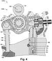
- Fig. 4 shows the result if cam 127 is rotated while latch pin 133 is in the non-engaging position.
- the downward force on cam follower 119 may be distributed between valve 106 and torsion springs 159.
- Torsions springs 159 may be tuned relative to valve spring 105 such that torsion springs 159 yield in the non-engaging configuration while valve spring 105 does not.
- Inner arm 111A may descend as torsion springs 159 wind and outer arm 111B may remain in place.
- valve 106 may remain on its seat 102 even as cam 127 rotates.
- cam shaft 125 still does work on rocker arm assembly 106 as cam 127 rises of base circle. But in this case, most of the energy is taken up by torsions springs 159, which act as lost motion springs.
- Electromagnetic latch assembly 150A is powered through inductive power transfer from coil 155 to coil 149.
- Fig. 5 and 6 provide diagrams of example circuits 231 and 235 that may be used for that purpose.
- coil 155 is part of a circuit 235A that also includes an oscillator 237 and a DC power source 239.
- oscillator 237 may be coupled to power source 239.
- Power source 239 may be, for example, a battery or an alternator. This coupling may be regulated through control circuitry (not shown).
- the control circuitry may include an engine control unit (ECU).
- Fig. 7 is a flow chart of a method 400 that may be used to operate the engine 117A using the circuitry of Fig. 5 or 6 .
- Method 400 begins with act 401, determining whether the engaging position is desired for latch pin 133. That determination may be made by an ECU and may relate to operating parameters for engine 117A such as speed and torque. A further determination may then be made in act 403A or 403B as to whether circuit 235A is currently closed. If the answer is yes and the engaging position is desired, method 400 proceeds with act 407 to open circuit 235A, disengaging coil 155 from its power source 239. If the answer is no and the engaging position is not desired, method 400 proceeds with act 407 to close circuit 235A and energize coil 155. In other cases, no action need be taken.
- coil 149 may be connected with solenoid 139 through a full wave rectifier 233 as illustrated by circuit 231A.
- coil 149 may be connected with solenoid 139 through a half wave rectifier 243 as illustrated by circuit 231B.
- the half wave rectifier 243 reduces power as compared to the full wave rectifier 233, half wave rectifier 243 allows coil 149 to be connected to solenoid 139 using only a single wire 143.
- a ground connection 245 may be made through a structural element such as the body of outer arm 111B.
- a capacitor 241 may be provided to steady the power supply to solenoid 139.
- solenoid 139 may have sufficient capacitance that capacitor 241 is unnecessary.
- the coupling factor between coils 155 and 149 may be 0.3 or greater.
- the relative sizes and positioning of coils 149 and 155 may facilitate achievement of this coupling factor.
- the spacing 152 between coils 155 and 149 may be made 2 cm or less. This spacing 152 may be less than five times the diameter 154 of the windings in coil 155 and less than five times the diameter 148 of the windings in coil 149. In some of these teachings, spacing 152 is less than either diameter 148 or 154. In the present context, if the larger of diameters 148 and 154 is 50% or less above the smaller, diameters 148 and 154 are considered similar.
- outer arm 111B to which coil 149 is mounted may remain stationary relative to coil 155.
- Outer arm 111B may be raised up or down slightly due to the action of HLA 165, but outer arm 111B still remains substantially stationary.
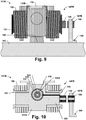
- FIGs. 8-10 illustrate an internal combustion engine 117B in which coils 149 and 155 are mounted to undergo relatively little motion even as outer arm 111B to which coil 149 is mounted pivots on HLA 165.
- coil 149 is mounted proximate the axis on which outer arm 111B pivots, which may run through spring posts 185.
- coil 149 may be mounted directly to a spring post 185.
- Torsion springs 159 may be mounted on hubs 183 that fit over spring posts 185.
- Coil 149 may pivot relative to coil 155 due to motion of outer arm 111B. The effect of that pivoting on inductive coupling between coils 149 and 155 may be negligible.
- coil 155 is supported by a mounting frame 187B, which may be held by a blot 189 to cylinder head 103. This configuration securely holds coil 155, but may require an extra bore within cylinder head 103. Mounting to a cam carrier (not shown) avoids the extra bore and is one way in which the mounting of coil 155 may be provided together with the rest of valvetrain 115B.
- Fig. 11 illustrates an internal combustion engine 117C having a rocker arm assembly 147C that include an outer arm 111B to which coil 149 is mounted and a mounting frame 187C that holds coil 155.
- Mounting frame 187C is carried by a portion of rocker arm assembly 147C that may undergo relatively little motion relative to cylinder head 103.
- mounting frame 187C may attach coil 155 to HLA 165. Securing mounting frame 187C to a part of rocker arm assembly 147C such as HLA 165 may facilitate controlling the spacing between coils 149 and 155.
- rocker arm assembly 147C Another advantage of securing coil 155 to rocker arm assembly 147C is that it facilitates installation of a rocker arm assembly 147C along with a system for powering electromagnetic latch assemblies 150A. Additional utility may be gained by securing HLA 165 to rocker arms 111 prior to installation.
- Fig. 12 shows rocker arm assembly 147C with a temporary connector 197 that may be used for this purpose.
- Connector 197 may be joined to mounting frame 187C or independently mounted to HLA 165.
- Connector 197 may be a breakaway connector that is adapted to be easily torn off after installation of rocker arm assembly 147C in cylinder head 103.
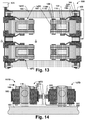
- Mounting frame 187C may extend to encompass a plurality of rocker arm assemblies 147C as shown in Fig. 13 .
- the overall structure may be referred to as a valve actuation module 199.
- Forming valve actuation module 199 may facilitate the installation of a plurality of rocker arm assemblies 147C in cylinder head 103 with a single operation.
- a wiring harness 193 may also be attached to mounting frame 187C, using connectors 195 as shown in Fig. 11 for example.
- Wiring harness 193 may carry wires supplying power to a plurality of coils 155.
- Wiring harness 193 may provide a single plug 174 through which the plurality of coils 155 may be connected to an electrical system of internal combustion engine 117C.
- FIG. 14 provides an example of an engine 117D in which a coil 155 is positioned to power two coils 149, each mounted to an outer arm 111B in one of two adjacent rocker arm assemblies 147D.
- Coil 155 may be held in position by a mounting frame 187D.
- Mounting frame 187D may be attached to HLA's 165 of two adjacent rocker arm assemblies 147D.
- hydraulic lash adjuster (HLA) 165 may include an inner sleeve 161 and an outer sleeve 163. Hydraulic lash adjuster 165 may be replaced by another type of lash adjuster or by a static fulcrum. Lash adjustment may be implemented using a hydraulic chamber 175 that is configured to vary in volume as hydraulic lash adjuster 165 extends or contracts through relative motion of inner sleeve 161 and outer sleeve 163.
- a supply port 170 may allow a reservoir chamber 172 to be filled from an oil gallery 168 in cylinder head 103.
- the fluid may be engine oil, which may be supplied at a pressure of about 2 atm.
- the example internal combustion engines 117 illustrated herein all have end pivot overhead cam (OHC) type valvetrains 115. But some of the present teaching are applicable to internal combustion engines having other types of valvetrains including, for example, other types of OHC valvetrains and overhead valve (OHV) valvetrains that may include rocker arm assemblies that are latched.
- the rocker arm assemblies 106 illustrated herein are all cylinder deactivating rocker arms. But some of the present teaching are applicable to switching rocker arms and other types of rocker arm assemblies.
- a mounting frame 187 may attach to the outer sleeve 163 of an HLA 165. If a mounting frame 187 is attached to only a single HLA 165, there may be some special provision to prevent mounting frame 187 from rotating.
- One option is to provide outer sleeve 163 with an anti-rotation guide. Inner sleeve 161 may still be allowed to rotate within outer sleeve 163 to reduce uneven wear at the interface with outer arm 111B.
- Another option is to extend the mounting frame 187 to contact two or more HLAs 165, as does mounting frame 187D of Fig. 14 .
- Fig. 15 illustrates an internal combustion engine 117E having a valvetrain 115F that includes a rocker arm assembly 147E.
- Rocker arm assembly 147E includes an outer arm 111B within which there is installed an electromagnetic latch assembly 150E.
- Electromagnetic latch assembly 150E includes two annular permanent magnets 201A and 201B positioned within solenoid 139 with confronting polarities and with a low coercivity ferromagnetic ring 203 between them. Permanent magnets may be rigidly mounted with respect to solenoid 139 and outer arm 111B.
- Electromagnetic latch assembly 150E is bi-stable in that it provides both extended and retracted positions in which latch pin 133 is stable independently from solenoid 139. As a consequence, either the latched or unlatched configuration can be reliably maintained without solenoid 139 being powered.
- Positional stability refers to the tendency of latch pin 133 to remain in and return to a particular position. Stability is provided by restorative forces that act against small perturbations of latch pin 133 from a stable position. In accordance with some of the present teachings, stabilizing forces are provided by permanent magnets 201.
- one or more springs may be positioned to provide positional stability. Springs may also be used to bias latch pin 133 out of a stable position, which may be useful for increasing actuation speed.
- FIGs. 16-18 illustrate the operation of electromagnetic latch assembly 150E.
- Fig. 16 shows electromagnetic latch assembly 150E with latch pin 133 in the extended position.
- Fig. 18 shows electromagnetic latch assembly 150E with latch pin 133 in the retracted position.
- solenoid 139 is de-energized.
- Fig. 17 illustrated latch pin 133 in a transitional state with solenoid 139 energized and driving latch pin 133.
- Electromagnetic latch assembly 150E may include various low coercivity ferromagnetic elements that are operative as pole pieces and positioned to form magnetic circuits for flux from permanent magnets 201. These include pieces 137 forming a shell around solenoid 139 and annular rings 211. Annular rings 211 may be shaped to mate with stepped edges of low coercivity ferromagnetic ring 135 mounted to latch pin 133. During actuation, magnetic flux may cross an air gap between one of these stepped edge and a mating ring 211, in which case the stepped edge may be operative to increase the magnetic forces through which latch pin 133 is actuated.
- permanent magnet 201A stabilizes latch pin 133 in both the extended and the retracted positions.
- magnetic circuit 216A is operative to be the primary path for magnet flux from permanent magnet 201A when latch pin 133 is in the extended position, absent magnetic fields from solenoid 139 or any external source that might alter the path taken by flux from permanent magnet 201A. Perturbation of latch pin 133 from the extended position would introduce an air gap into magnetic circuit 216A, increasing its magnetic reluctance. Therefore, the magnetic field produced by permanent magnet 201A resists such perturbations.
- magnetic circuit 214B is operative to be the primary path for magnet flux from permanent magnet 201A when latch pin 133 is in the retracted position, absent magnetic fields from solenoid 139 or any external source that might alter the path taken by flux from permanent magnet 216A. Perturbation of latch pin 133 from the retracted position would introduce an air gap into magnetic circuit 214B, increasing its magnetic reluctance. Therefore, the magnetic field produced by permanent magnet 201A resists those perturbations as well.
- Figs. 16 and 18 show that permanent magnet 201B also stabilizes the position of latch pin 133 in both the extended and retracted positions. In the extended position, magnetic flux from permanent magnet 201B primarily follows circuit 214A. In the retracted position, magnetic flux from permanent magnet 201B primarily follows circuit 216B.
- Electromagnetic latch assembly 150E is structured to operate through a magnetic flux path-shifting mechanism.
- Fig. 17 illustrates this mechanism for the case in which solenoid 139 is operated to induce latch pin 133 to actuate from the extended position to the retracted position.
- a voltage of suitable polarity may be applied to solenoid 139 to induce magnetic flux following the circuit 218.
- the magnetic flux from solenoid 139 may reverse the magnetic polarity in low coercivity ferromagnetic elements forming the magnetic circuits 214A and 216A through which permanent magnets 201 stabilized latch pin 133 in the extended position. This greatly increases the reluctance of magnetic circuit 214A and 216A.
- Magnetic flux from permanent magnets 201 may thus be driven to shift from magnetic circuits 214A and 216A toward magnetic circuits 216B and 214B.
- the net magnetic forces on latch pin 133 may drive it to the retracted position shown in Fig. 18 .
- the total air gap in the magnetic circuit 218 taken by flux from solenoid 139 may not vary significantly as latch pin 133 actuates. This feature relates to operability through a flux path-shifting mechanism.
- Magnetic circuits 216A and 216B are short magnetic circuits between the poles of permanent magnets 201A and 201B respectively. Magnetic circuits 216 pass through low coercivity ferromagnetic portion 135 of latch pin 133 but not around the coils of solenoid 139. These short magnetic circuits may reduce magnetic flux leakage and allow permanent magnets 201 to provide a high holding force for latch pin 133. Magnetic circuits 214, on the other hand, pass around the coils of solenoid 139. Routing these magnetic circuits around the outside of solenoid 139 may keep them from interfering with the shorter magnetic circuits.
- a permanent magnet is a high coercivity ferromagnetic material with residual magnetism.
- a high coercivity means that the polarity of permanent magnet 201 remains unchanged through hundreds of operations through which electromagnetic latch assembly 150E is operated to switch latch pin 133 between the extended and retracted positions.
- Examples of high coercivity ferromagnetic materials include compositions of AINiCo and NdFeB.
- permanent magnets 201 may initially hold latch pin 133 in a first position, at some point during latch pin 133's progress toward the second position, permanent magnets 201 begin to attract latch pin 133 toward the second position. Accordingly, at some point during latch pin 133's progress, solenoid 139 may be disconnected from its power source and latch pin 133 will still complete its travel to the second position. This feature may lend itself to coupling a switch that alter the polarity of voltage applied to solenoid 139 to the movement of latch pin 133.
- Electromagnetic latch assembly 150A forms an air gap 140 shown in Fig. 2 .
- Moving latch pin 133 toward the retracted position tends to reduce air gap 140, which reduces the magnetic reluctance in a path taken by flux from solenoid 139.
- electromagnetic latch assembly 150A energizing solenoid 139 causes latch pin 133 to move toward the retracted position regardless of the direction of the current through solenoid 139 or the polarity of the resulting magnetic field.
- latch pin 133 may be moved in either one direction or another depending on the polarity of the magnetic field generated by solenoid 139.
- a switch may be configured to vary the polarity of the magnetic field generated by solenoid 139.
- the switch is used to select between two rectifiers in a circuit connecting coil 149 to solenoid 139.
- Figs. 19 and 20 provide an example in which a single-pole, double-throw switch 247A is configured in a circuit 231B to select between two half wave rectifier 243 positioned between coil 149 and solenoid 139.
- the switch 247 is configured to select the polarity with which a DC voltage is applied to coil 139.
- a double-pole, double-throw switch 247B is configured in a circuit 231C to select between the polarity with which the output poles of full wave rectifier 233 are connected to the poles of solenoid 139.
- switch 247 may select which of two coil of solenoid 139 is powered. One of the coils may be wound in a first direction and the other may be wound in the opposite direction. One or the other set of coils may be energized depending on the position in which it is desired to place latch pin 133.
- Switch 247 may be implemented with circuitry. But in some of these teachings, switch 247 is mechanical. A mechanical switch may be actuated by movement of the latch pin 133. With reference to Fig. 16 , electromagnetic latch assembly 150E includes switch 247C, which is an example of such a switch. Switch 247C includes connectors 205, which may be spring loaded connectors. A conductive strip 207 with an insulated backing may be to mounted latch pin 133. Conductive strip 207 may be mounted to latch pin 133 through low coercivity ferromagnetic ring 135. Conductive strip 207 is of such a length that it will connect just two of the three wires 207 at any one time, depending on the position of latch pin 133. The identity of the pair of wires 207 that are connected determines the position of switch 247C.
- Fig. 21 provides a flow chart for a method 410 for operating engine 117E or the like using the switch 247C or any other switch that automatically toggles each time electromagnetic latch assembly 150E is actuated.
- Method 410 begin with act 401, determining whether the engaging position is desired for latch pin 133.
- Method 410 continues with an act 409 of determining whether latch pin 133 is currently in the engaging position. This may be implemented with software that tracks the position of latch pin 133. In some of these teachings, however, a mechanism is provided to determine the current position of latch pin 133. Any suitable mechanism may be used to determine the current position of latch pin 133.
- measurements of voltage, current, resistance, or impedance in circuit 235A or other circuit that includes coil 155 are made and the measurements used to determine the position of latch pin 133.
- the impedance of coil 155 may vary with the position of coil 149.
- the position of coil 149 may vary in relation to the phase of cam shaft 125 in a way that depends on the position of latch pin 133.
- Coil 155 may be pulsed one or more times over the cam cycle with a current too short in magnitude or duration to actuate latch pin 133 in order to gather the desired data.
- method 410 continues with act 405, energizing coil 155 to power circuit 231 and solenoid 139 causing latch pin 133 to actuate.
- switch 247C may open.
- method 410 may disengage power transmission at approximately this point in time.
- Act 411 may operate by estimating the time required for actuation of latch pin 133.
- Electronic module 209 may include circuitry to delay engagement of switch 247C with reverse polarity in order to increase the time window before continued powering of coil 155 results in the polarity of voltage applied to solenoid 139 being reversed.
- circuit 235 is so monitored and power disengaged accordingly.
- solenoid 139 Even with optimal timing, power to solenoid 139 may be interrupted before latch pin 133 completes its translation from one position to the other. Nevertheless, translation in the desired direction may be expected to complete.
- solenoid 133 has reached the half way point, the polarity in shell 137 and other components of magnetic circuits 214 and 216 has been reversed and translation may complete under the action of magnets 201.
- FIG. 25 illustrates an internal combustion engine 117F providing an example.
- Internal combustion engine 117F include a rocker arm assembly 147F with two coils 149A and 149B mounted to outer arm 111B.
- Each of the coils 149 is inductively coupled with a coil 155 mounted off rocker arms 111.
- one of the coils 149 powers a solenoid 139 in a circuit 231 while the other of the coils 149 controls a switch 247 that is configured to determine the polarity of the magnetic field generated by solenoid 139.
- one of the coils 149 is configured to extend latch pin 133 and the other to retract latch pin 133.
- Fig. 26 provides a diagram for circuits 235A and 231F that may be used for this purpose.
- full wave rectifier 233A may be configured to supply DC voltage to solenoid 139 with a first polarity when coil 149A is driven with an AC current.
- Full wave rectifier 233B may be configured to supply DC voltage to solenoid 139 with a reverse of the first polarity when coil 149B is driven with an AC current.
- Transistors 249 may be configured to prevent shorting around solenoid 139 when one or the other of the coils 149 is driven.
- Inductively coupled coils 149 and 155 as described herein may also be used for communication between an electrical device 139 mounted to a rocker arm 111 and a controller mounted off the rocker arm.
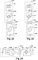
- Fig. 24 provides an example in which a sensor 139B communicates with an engine control unit (ECU) 255.
- ECU engine control unit
- sensor 139B produces an AC current output that is used to drive coil 149.
- sensor 139B produces a DC output that is used to drive an oscillator 237, which in turn drives coil 149.
- a switch that controls the driving of coil 149 from a power source 251 is controlled from the output of sensor 139B.
- Coil 149 may drive coil 155.
- the output of coil 155 may be processed and conveyed to ECU 255.
- sensor 139B is configured in a circuit that varies the impedance of coil 149 according to the sensor 139B's output.
- the impedance of coil 149 may be queried by ECU 255.
- ECU 255 may pulse coil 155 and sample the response in circuit 235D.
- Sensor 139B may be powered in any suitable manner.
- sensor 139B itself may be operative to generate power.
- sensor 139B may be an accelerometer that generates power when a rocker arm 111 to which sensor 139B is mounted accelerates.
- power source 251 is mounted to rocker arm assembly 147, is separate from sensor 139B, and is configured to generate power from motion of rocker arm assembly 147.
- a generator 251 is a piezoelectric generator.
- a generator 251 is an electromagnetic generator.
- a generator 251 is configured to generate power from vibrations of rocker arm assembly 147.
- a generator 251 is configured within a force transmission pathway of rocker arm assembly 147 or is otherwise configured to be driven by a cam 127.
- power source 251 may be an energy storage device such as a battery or capacitor.
- an energy source 251 is charged from energy inductively transferred from a coil 155 off rocker arm 111 to a coil 149 mounted on the rocker arm 111.
- An additional pair of inductively coupled coils 149 and 155 may be provide to power a circuit 231D including sensor 139B.
- magnetic components of an electromagnetic latch assembly 150 are mounted within a chamber 156 formed in outer arm 111B.
- the magnetic component housed in chamber 126 may include solenoid 139, permanent magnets 201, or both.
- chamber 126 is sealed against intrusion from metal particles that may be in oil dispersed throughout the surrounding rocker arm assembly 106.
- chamber 156 is a hydraulic chamber. Chamber 156 may have been adapted to house parts of electromagnetic latch assembly 150.
- rocker arm assembly 106 is made using rocker arms 111 put into production for use with a hydraulically actuated latch.
- an electric latch assembly 150 has been installed in place of a hydraulic latch. While chamber 156 is a hydraulic chamber, it need not be functionally connected to a hydraulic system.
- a hydraulic passage 158 may connect to chamber 156. Hydraulic passage 158 may be blocked to help seal chamber 156. In some of these teaching, hydraulic passage 158 couples with a hydraulic passage 160 formed in hydraulic lash adjuster 165.
- hydraulic lash adjuster 165 may have been originally designed for use with a hydraulically latching rocker arm assembly. Accordingly, a second supply port 166 may be formed in hydraulic lash adjuster 165 and communicate with a second reservoir chamber 167 in hydraulic lash adjuster 165. Cylinder head 103 may not include any provision for supplying oil to second supply port 161. Second reservoir chamber 167 may be isolated from any substantial flow of hydraulic fluid in cylinder head 103. Reservoir chamber 167 and hydraulic passages communicating therewith may be essentially non-functional in engine 117.
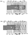
- Electromagnetic latch assembly 150G of Figs. 27-31 provides an example in which both the extended and retracted positions are stabilized by springs. Electromagnetic latch assembly 150G is operative to toggle between the retracted and the extended positions in response to repeated application of a force in one direction using solenoid 139, which may be powered as described elsewhere herein. Electromagnetic latch assembly 150G may include a cam 315 configured to rotate in response to a translation of latch pin 133G. In the illustrated design, latch pin 133G is operative as a cam follower. Latch pin 133G may include teeth 321 that interface with teeth 319 of cam 315. Teeth 319 and 321 may be arranged radially about perimeters of latch pin 133G and cam 315 respectively. One or more fins 303 may extend from solenoid 139 or another member fixedly positioned with respect to latch pin housing 325 and fit between teeth 319, constraining the rotation of latch pin 133,
- Fig. 27 provides a partial cutaway top view showing electromagnetic latch assembly 150G in its retracted position.
- Fig. 28 provides a similar view showing electromagnetic latch assembly 150G in its extended position.
- Plunger 305 which is an extension of cam 315, may extend into a chamber 309 formed centrally within latch pin 133G and may be retained there by a spring 307. In both the retracted an extended positions, latch pin 133G and cam 315 may be held in abutment by spring 307. In the retracted position, motion of cam 315 to the left may be prevented by interference between cam teeth 319 and fin 303. Latch pin 133G may be susceptible to displacement slightly to the left relative to cam 315. This motion may be restricted and countered by spring 307.
- Displacing latch pin 133G to the right may also displace cam 315, which collective motion may be resisted and countered by spring 317.
- Latch pin 133G may thus be stabilized in the retracted position by springs 317 and 307.
- a portion of cam 315 abutting spring 317 may be formed as a separate part from the main body of cam 315 to facilitate rotation of cam 315.
- Figs. 29-31 show electromagnetic latch assembly 150G at intermediate stages in a process of actuating to transition latch pin 133G from the retracted to the extend position. Essentially the same process may be employed to actuate latch pin 133G back to the retracted position. The process begins by energizing solenoid 139 to produce actuating force 326 on latch pin 133G by. Latch pin 133G may be formed with low coercivity ferromagnetic material, whereby drawing latch pin 133G into solenoid 139 reduces the reluctance in a path taken by flux from solenoid 139. This action is the same regardless of the direction of current through solenoid 139.
- actuating force 326 may drive latch pin 133G and cam 315 deeper into latch pin housing 325.
- Angled faces 310 of latch pin teeth 321 may act against angled faces 312 of cam teeth 319 to place a rotational force 314 on cam 315.
- Rotation of cam 315 may be resisted by fin 303 until cam teeth 319 clear fin 303.
- Fig. 29 shows electromagnetic latch assembly 150G at the point where cam teeth 319 are just clearing fin 303 and rotation of cam 315 may begin. From this point, cam 315 may rotate under the influence of force 326 until the tips 306 of cam teeth 319 encounter angled faces 322 of latch pin teeth 321 as shown in Fig. 30 .
- spring 317 may drive cam 315 to the left as shown in Fig. 31 .
- a rotational force 314 may result on cam 315 from the interaction between an angled face 312 of a cam tooth 321 and fin 303. This may cause further rotation of cam 315.
- tips 306 of cam teeth 319 may press against angled faces 322 of latch pin teeth 321.
- a resultant force may compress spring 307 creating clearance for cam teeth 319 to rotate past latch pin teeth 321.
- Rotation of cam 315 may continue until slots 311 between adjacent cam teeth 319 align with fin 303 allowing cam 315 and latch pin 133G to extend under the influence of spring 317 until the extended position of Fig. 28 is reached.
Landscapes
- Engineering & Computer Science (AREA)
- Mechanical Engineering (AREA)
- General Engineering & Computer Science (AREA)
- Power Engineering (AREA)
- Physics & Mathematics (AREA)
- Electromagnetism (AREA)
- Valve Device For Special Equipments (AREA)
- Valve-Gear Or Valve Arrangements (AREA)
Description
- The present teachings relate to valvetrains, particularly valvetrains providing variable valve lift (WL) or cylinder deactivation (CDA).
- Hydraulically actuated latches are used on some rocker arm assemblies to implement variable valve lift (WL) or cylinder deactivation (CDA). For example, some switching roller finger followers (SRFF) use hydraulically actuated latches. In these systems, pressurized oil from an oil pump may be used for latch actuation. The flow of pressurized oil may be regulated by an oil control valve (OCV) under the supervision of an engine control unit (ECU). A separate feed from the same source provides oil for hydraulic lash adjustment. In these systems each rocker arm assembly has two hydraulic feeds, which entails a degree of complexity and equipment cost. The oil demands of these hydraulic feeds may approach the limits of existing supply systems.
- The complexity and demands for oil in some valvetrain systems can be reduced by replacing hydraulically latched rocker arm assemblies with electrically latched rocker arm assemblies. Electrically latched rocker arm assemblies require power. Regardless of whether electric latches are used, there has been a long felt need to provide sensors on switching and cylinder deactivating rocker arm assemblies to provide diagnostic information.
-
DE 103 10 220 A1KR 20130133545 WO 2016/028812 A1 .US 2004/0244474 A1 relates to a system for transmitting tire condition variables from a transmission device mounted on a motor vehicle to a control unit arranged in the area of the vehicle body, which is detachably fastened to a motor vehicle wheel. - The invention relates to a valvetrain for an internal combustion engine as defined in claim 1.
- According to some aspects of the present teachings, a first electrical circuit includes the electrical device and a first conductor that is mounted to the rocker arm and a second electrical circuit includes a second conductor mounted off the rocker arm. The second conductor may be mounted in a position that is stationary relative to the cylinder head. The first and second conductors are inductively coupled to an extent that enables effective power transfer or communication between the first and second circuits. In these teachings, the first and second conductors are mutually-inductively coupled. The mutually-inductively coupled conductors are coils, a first coil forming part of the first circuit and a second coil forming part of the second circuit. Having the conductors wound into coils may increase mutual inductance.
- In some of these teachings the coils are wound about laminated cores. Laminated cores are desirable for AC power transfer. AC power transfer may provide higher power transfer efficiencies as compared to DC power transfer for coils of similar size and proximity. In some of these teachings, the second circuit is configured to drive the second coil with AC power in the range from 50kHz to 1MHz. AC power transfer through inductive coupling may be most efficient in that range.
- A high coupling factor between the inductively coupled coils may be necessary for some of the applications contemplated herein to be practicable. In some of these teachings, the coils are mounted whereby the spacing between coils is less than 2 cm. In some of these teachings, the coils are similar in diameter. In some of these teachings, the coils are mounted whereby the spacing between them is less than five times the diameter of the windings in one of the coils. In some of these teachings, the coils have central axes that are substantially aligned. These dimensions may provide a high coupling factor between the first and second coils. In some of these teachings, the coupling factor is at least 0.1. In some of these teachings, the coupling factor is at least 0.3. A coupling factor of 0.3 is generally achievable according to the teachings herein. To the extent that the two coils undergo relative motion with rocker arm assembly operation, it is sufficient if the dimensions and coupling factors referred to in this paragraph are satisfied within only a portion of that range of relative motion. In some of these teachings, one or more pole pieces are configured to facilitate inductive power transfer between the first and second coils. The pole pieces may guide magnetic fields generated by the second coil toward the first coil and thereby create additional flexibility in positioning and sizing the first and second coils.
- In some of these teachings, the second coil is mounted to a hydraulic lash adjuster. In some of these teachings, the second coil is mounted to a cam carrier. In some of these teachings, the second coil is mounted to a cylinder head. Any of these may be a suitable location for mounting the coil of a second circuit in such a way that it can be wired without any of the wires being forced to undergo excessive motion.
- In some of these teachings, a sensor is mounted to the rocker arm. The sensor may be operable to communicate with the control unit of the engine through the first and second circuits. In some of these teachings, the sensor is operative to generate power. In some of these teachings, the sensor is an accelerometer. In some of these teachings, the first circuit includes a generator mounted to the rocker arm assembly in addition to the sensor. In some of these teachings, the first circuit includes an oscillator for generating an AC current from a DC power source.
- In some of these teachings, the rocker arm assembly includes an electromagnetic latch assembly having a latch pin and a solenoid powered through the first electrical circuit. In some of these teachings, the first electrical circuit includes a rectifier positioned to convert AC power inductively transferred to the first coil into DC power for energizing the solenoid. A solenoid energized with DC power may be made more compact than one energized with AC power. The latch pin may have first and second positions. One of these may be an extended or engaging position while the other is a retracted or non-engaging position. With the latch pin in the first position, the rocker arm assembly may be operative to actuate the poppet valve in response to rotation of the cam shaft to produce a first valve lift profile. With the latch pin in the second position, the rocker arm assembly may be operative to actuate the valve in response to rotation of the cam shaft to produce a second valve lift profile, which is distinct from the first valve lift profile, or the poppet valve may be deactivated.
- In some of these teaching, the rocker arm assembly is configured to keep the rocker arm to which the electrical device is mounted substantially stationary relative to the cylinder head while the solenoid is energized. This configuration facilitates inductive power transfer over extended periods because the mutually inductively coupled coils may remain substantially stationary relative to one another as long as the solenoid remains energized. In some of these teachings, the first coil of the first circuit is mounted proximate an axis of pivoting or rotation of the rocker arm. In some of these teachings, the first coil is mounted to a spring post of the rocker arm. In this configuration, rocker arm motion may have relatively little effect on the spacing between the mutually inductively coupled coils allowing power transfer to occur regardless of where the rocker arm is in its range of motion.
- In some of these teachings, an electromagnetic latch assembly is bi-stable in the sense of being structured to stably maintain the latch pin's position independently from the solenoid both when the latch pin is in the first position and when the latch pin is in the second position. With this structure, power does not need to be provided to the electromagnetic latch assembly accept to switch the latch pin position. With that structure, the inductive coupling need only be effective at a single point within the range of motion of the rocker arm to which the first coil is mounted. In some of these teachings, the rocker arm assembly is operative to move the first coil through a range of motion relative to the second coil as the cam follower is lifted by the cam. In some of these teachings, the portion of the range of motion over which the mutual inductive coupling is effective for power transfer includes the position at which the rocker arm resides when the cam is on base circle. In some of these teachings, the coils are mounted such that their closest approach occurs when the cam is on base circle.
- In some aspects of the present teachings, the bi-stable latch is operative to toggle between the first and the second positions in response to repeated application of a force in one direction. The electromagnetic latch assembly may then be actuated in either direction by briefly powering the solenoid, even if the solenoid is configured to apply force in only one direction. In some of these teachings, the electromagnetic latch assembly includes a latch cam configured to rotate in response to a translation of the latch pin. In some of these teachings, a set of one or more springs or magnets may maintain the latch pin in either the extended or the retracted position according to the angular position of the latch cam.
- According to some aspects of the present teachings, a bi-stable electromagnetic latch assembly includes a permanent magnet that contributes to the positional stability of the latch pin both when the latch pin is in the first position and when the latch pin is in the second position. According to some further aspects of these teachings, the electromagnetic latch assembly is structured to operate through a magnetic flux path-shifting mechanism. The electromagnetic latch assembly may provide two distinct magnetic circuits, one or the other of which is operative to be the primary path for magnet flux from the permanent magnet depending on the whether the latch pin is in the first position or the second position, absent magnetic fields from the solenoid or any external source that might alter the path taken by the magnetic flux. In some of these teachings, actuating the latch pin may involve using the solenoid to redirect the permanent magnet's flux from the one circuit to the other. An electromagnetic latch assembly structured to be operable through a flux path-shifting mechanism may be smaller than one that is not so structured. In some of these teachings, the permanent magnet is fixedly mounted to the rocker arm. Fixing the permanent magnet to the rocker arm means not fixing the permanent magnet to the latch pin. Taking the weight of the permanent magnet off the latch pin may increase actuation speed and allow the use of a smaller solenoid.
- In some of the present teaching, the electromagnetic latch assembly includes at least one permanent magnet and the internal combustion engine has circuitry operable to energize the solenoid with a current in either a first direction or a second direction, which is the reverse of the first direction. The solenoid powered with current in the first direction may be operative to actuate the latch pin from the first position to the second position. The solenoid powered with current in the second direction may be operative to actuate the latch pin from the second position to the first position. In some of these teachings the two solenoids may be provided as two coils having windings in opposite directions. One or the other coil may be energized depending on the desired direction of the current. Employing two solenoid coils may simplify the control circuitry. Employing only one solenoid coil may provide the most compact design.
- Some aspects of the present teachings relate to structures for powering a solenoid on a rocker arm with direct current (DC) in either a first direction or a second direction from alternating current (AC) induced in one more conductors mounted to the rocker arm. In some of these teachings, two coils for receiving AC power are mounted to the rocker arm. Each of the two coils may be inductively coupled with another coil that is mounted off the rocker arm. In some of these teachings, the two coils are located on opposite sides of the rocker arm. Circuitry on the rocker arm may be structured whereby inducing an alternating current in one of the inductively coupled coils mounted to the rocker arm results in direct current through the solenoid in a first direction and inducing an alternating current in the other inductively coupled coil mounted to the rocker arm results in direct current through the solenoid in a reverse of the first direction. Alternatively, the circuitry may connect the inductively coupled coils mounted to the rocker arm to one of two solenoid coils that have opposite windings in opposite directions. The circuitry may include rectifiers, one in association with each of the inductively coupled coils.
- In some of these teachings, the rocker arm assembly includes a switch. In some of these teachings, the switch is configured to control the direction in which DC current is driven through the solenoid when AC current is induced in an inductively coupled coil. The switch may be implemented with circuitry. But in some of these teachings, the switch is a mechanical one that is tied to the movement of the latch pin. A mechanical switch may be more reliable than one that relies on capacitors and the like, which may not perform consistently over the range of temperatures that occur during operation of the internal combustion engine. In some of these teachings, the switch selects between one of two rectifying circuits. In some of these teachings, the switch selects the polarity with which a DC voltage source is coupled to the solenoid. In some alternative teachings, the switch selects between which of two solenoid coils is powered. The coils may have opposite windings whereby one coil actuates the latch pin in one direction while the other actuates the latch pin in the opposite direction.
- Some aspects of the present teachings relate to an internal combustion engine that includes a plurality of poppet valves having seats within the cylinder head, a plurality of eccentrically shaped cams mounted on one or more cam shafts, and a plurality of rocker arm assemblies comprising cam followers each configured to engage one of the cams as it rotates and each operative to transmit force from that cam to actuate one of the valves. A plurality of these rocker arm assemblies may have a rocker arm that is mobile relative to the cylinder head and to which a conductor mounted. Each of these conductors may be mutually-inductively coupled with another conductor mounted off the rocker arms. In some of these teachings, the mutually-inductively coupled conductors mounted on and off the rocker arms are coils. In some of these teachings, there is a distinct coil mounted off the rocker arms for each inductively coupled coil mounted to one of the rocker arms. In some of these teachings, there is one distinct coil mounted off the rocker arms for every two coils mounted to one of the rocker arms. In some of these teachings, the distances between the mutually-inductively coupled coils are substantially less than the distances between rocker arm assemblies. A coil mounted off the rocker arms may be located between and mutually inductively coupled with each of two coils mounted on rocker arms of adjacent rocker arm assemblies. According to some aspects of the present teachings, the internal combustion engine further includes a framework to which a plurality of the second coils are mounted. The framework may facilitate installation and positioning of the multiple coils.
- Some aspects of the present teachings relate to a method of operating one of the foregoing internal combustion engines. The method includes making one more measurements of voltage, current, resistance, or impedance in the second circuit and using the measurements to make a diagnostic determination regarding the rocker arm assembly. The diagnostic determination may relate to the proximity of the first and second coils. In some of these teachings, the diagnostic determination relates to whether a rocker arm assembly latch is engaged. In some of these teachings, the second circuit is pulsed in relation to making one or more of the measurements.
- Some aspects of the present teachings relate to a valve actuation module or a method of manufacturing an internal combustion engine as previously described using the valve actuation module. The valve actuation module includes a frame to which is attached a group of parts including mutually inductively coupled first and second coils. In some of these teachings, a rocker arm assembly including a rocker arm and a hydraulic lash adjuster is attached to the frame. In some of these teachings, a plurality of rocker arm assemblies are attached to the frame. In some of these teachings, a wiring harness including wiring of the second circuit is attached to the frame. The method includes installing the valve actuation module in a cylinder head. This allows a plurality of parts to be installed simultaneously. In some of these teachings, a temporary connection holds a rocker arm and a hydraulic lash adjuster together while they are attached to the frame. The temporary connection can be a breakaway connector. The temporary connection can be removed after installation of the valve actuation module.
- The primary purpose of this summary has been to present certain of the inventors' concepts in a simplified form to facilitate understanding of the more detailed description that follows. This summary is not a comprehensive description of every one of the inventors' concepts or every combination of the inventors' concepts that can be considered "invention". Other concepts of the inventors will be conveyed to one of ordinary skill in the art by the following detailed description together with the drawings. The specifics disclosed herein may be generalized, narrowed, and combined in various ways with the ultimate statement of what the inventors claim as their invention being reserved for the claims that follow.
- Spatially relative terms, such as "beneath," "below," "lower," "above," "upper" and the like are used in the following detailed description to describe spatial relationships as illustrated in these drawings. Those relationships are independent from the orientation of any illustrated device in actual use.
-
Fig. 1 is a cross-sectional side view of a portion of an internal combustion according to some aspects of the present teachings including a rocker arm assembly in a non-engaging configuration and a cam on base circle. -
Fig. 2 provides the view ofFig. 1 , but with the rocker arm assembly in an engaging configuration. -
Fig. 3 provides the view ofFig. 2 , but with the cam risen off base circle. -
Fig. 4 provides the view ofFig. 1 , but with the cam risen off base circle. -
Fig. 5 is a diagram of first and second electrical circuits according to some aspects of the present teachings. -
Fig. 6 is a diagram of first and second electrical circuits according to some other aspects of the present teachings. -
Fig. 7 is a flow chart for a method according to some aspects of the present teachings. -
Fig. 8 provides a side view of a portion of an internal combustion engine according to some other aspects of the present teachings. -
Fig. 9 is a rear view of the internal combustion engine ofFig. 8 . -
Fig. 10 is cross-sectional view of the rocker arm assembly of the internal combustion engine ofFig. 8 taken along line 10-10 ofFig. 8 . -
Fig. 11 provides a rear view of a portion of an internal combustion engine according to some other aspects of the present teachings and corresponds to the view along line 11-11 ofFig. 13 . -
Fig. 12 provides a side view of a rocker arm assembly for the internal combustion engine ofFig. 11 and corresponds to the view along line 12-12 ofFig. 13 . -
Fig. 13 illustrates a valve actuation module according to some aspects of the present teachings. -
Fig. 14 provides a rear view of a portion of an internal combustion engine according to some other aspects of the present teachings. -
Fig. 15 is a cross-sectional side view of a portion of an internal combustion according to some aspects of the present teachings. -
Fig. 16 is a cross-sectional side view of an electromagnetic latch assembly used in the internal combustion engine ofFig. 15 with the latch pin in an extended position. -
Fig. 17 is a cross-sectional side view of an electromagnetic latch assembly used in the internal combustion engine ofFig. 15 with the solenoid energized and the latch pin in a transitional state. -
Fig. 18 is a cross-sectional side view of an electromagnetic latch assembly used in the internal combustion engine ofFig. 15 with the latch pin in a retracted position. -
Fig. 19 is a diagram of first and second electrical circuits according to some other aspects of the present teachings. -
Fig. 20 illustrates the same electrical circuits asFig. 19 , but with the switch position changed. -
Fig. 21 is a flow chart for a method according to some other aspects of the present teachings. -
Fig. 22 is a diagram of first and second electrical circuits according to some other aspects of the present teachings. -
Fig. 23 illustrates the same electrical circuits asFig. 22 , but with the switch position changed. -
Fig. 24 is a diagram of first and second electrical circuits according to some other aspects of the present teachings. -
Fig. 25 provides a rear view of a portion of an internal combustion engine according to some other aspects of the present teachings. -
Fig. 26 is a diagram of electrical circuits according to some other aspects of the present teachings. -
Fig. 27 illustrates a latch according to some aspects of the present teachings with the latch pin in a retracted position. -
Fig. 28 illustrates the latch ofFig. 27 with the latch pin in an extended position. -
Fig. 29 illustrates the latch ofFig. 27 in a first transitional state. -
Fig. 30 illustrates the latch ofFig. 27 in a second transitional state. -
Fig. 31 illustrates the latch ofFig. 27 in a third transitional state. - In the drawings, some reference characters consist of a number followed by a letter. In this description and the claims that follow, a reference character consisting of that same number without a letter is equivalent to a listing of all reference characters used in the drawings and consisting of that same number followed by a letter. For example, "
permanent magnet 201" is the same as "permanent magnet Permanent magnet 201 is there for a generic reference that includes the specific instancespermanent magnet 201A andpermanent magnet 201B. Where options are provided for one instance subject to a generic reference, those options are to be given consideration in connection with all instances subject to that generic reference. -
Figs. 1-4 illustrate aninternal combustion engine 117A in accordance with some of the present teachings. Referring toFig. 1 ,internal combustion engine 117A includescylinder head 103 andvalvetrain 115A.Valvetrain 115A includespoppet valve 106, which has aseat 102 withincylinder head 103,cam shaft 125, on which is mounted eccentricallyshaped cam 127, androcker arm assembly 147A.Rocker arm assembly 147A may includeinner arm 111A, to whichcam follower 119 is mounted,outer arm 111B, and hydraulic lashadjuster 165. Both rocker arms 111 are mobile relative tocylinder head 103.Cam follower 119 may be a roller follower and is configured to engagecam 127 ascam shaft 125 rotates.Rocker arm assembly 147A is operative to transmit force fromcam 127 to actuatevalve 106. - An
electrical device 139, which is solenoid 139A, and acoil 149, which is a conductor, are mounted toouter arm 111B.Solenoid 139A,coil 149, and additionalelectrical components 145, may be connected throughwires 143 to form a first electrical circuit 231 for whichFigs. 5 and 6 provide example diagrams. Anothercoil 155 is mounted offouter arm 111B. The mounting ofcoil 155 inengine 117A is not shown.Coil 155 may be mounted tocylinder head 103 or another component, such as a cam carrier, that is stationary relative to thecylinder head 103.Coil 155 may alternatively be mounted to hydraulic lashadjuster 165 or another component that may remain substantially stationary relative tocylinder head 103 whileouter arm 111B moves.Coil 155 is mounted in such a position that it is mutually inductively coupled withcoil 149 at least whencam 127 is on base circle as it is inFigs. 1 and2 . -
Coil 149 may be wound aboutlaminated core 151 andcoil 155 may be wound aboutlaminated coil 153.Laminated cores coils Coil 155 may be part of a second circuit 235 that is operative to provide such a driving current.Fig. 5 provides a diagram for an examplesecond circuit 235A that may be so operative. -
Solenoid 139A may be part of anelectromagnetic latch assembly 150A mounted toouter arm 111B.Electromagnetic latch assembly 150A may further include aspring 141 and alatch pin 133.Latch pin 133 may be formed of a low coercivity ferromagnetic material such as soft iron. Alternatively, a low coercivity ferromagnetic part such asannular ring 135 may be mounted to latchpin 133. Latch pin 33 is translatable between extended and retracted positions.Spring 141 may biaslatch pin 133 toward the extended position, which is shown inFig. 2 .Solenoid 139A may be operative when energized to exert a magnetic force on low coercivityferromagnetic ring 135 and drawlatch pin 133 to the retracted position, which is shown inFig. 1 . Ashell 137 of low coercivity ferromagnetic material may be formed aroundsolenoid 139A to increase the force of its action onlatch pin 133. - The extended position for
latch pin 133 may be described as an engaging position and provides an engaging configuration forrocker arm assembly 147A. Ifcam 127 is rotated whilelatch pin 133 is in the engaging position,latch pin 133 may engagelip 131 ofinner arm 111A. The force ofcam 127 oncam follower 119 may then cause bothinner arm 111A andouter arm 111B to pivot together onhydraulic lash adjuster 165, bearing down onvalve 106 and compressingvalve spring 105 as shown inFig. 3 .Valve 106 may thus be lifted off itsseat 102 with a valve lift profile determined by the shape ofcam 127. The valve lift profile is the shape of a plot showing the height by whichvalve 106 is lifted off itsseat 102 as a function of angular position ofcam shaft 125. In the engaging configuration,cam shaft 125 may do work on rocker arm assembly 147 ascam 127 rises off base circle. Much of the resulting energy may be taken up byvalve spring 105 and returned tocam shaft 125 ascam 127 descend back toward base circle. -
Fig. 4 shows the result ifcam 127 is rotated whilelatch pin 133 is in the non-engaging position. The downward force oncam follower 119 may be distributed betweenvalve 106 and torsion springs 159. Torsions springs 159 may be tuned relative tovalve spring 105 such that torsion springs 159 yield in the non-engaging configuration whilevalve spring 105 does not.Inner arm 111A may descend as torsion springs 159 wind andouter arm 111B may remain in place. As a result,valve 106 may remain on itsseat 102 even ascam 127 rotates. In the non-engaging configuration,cam shaft 125 still does work onrocker arm assembly 106 ascam 127 rises of base circle. But in this case, most of the energy is taken up by torsions springs 159, which act as lost motion springs. -
Electromagnetic latch assembly 150A is powered through inductive power transfer fromcoil 155 tocoil 149.Fig. 5 and 6 provide diagrams of example circuits 231 and 235 that may be used for that purpose. In both examples provided by these two figures,coil 155 is part of acircuit 235A that also includes anoscillator 237 and aDC power source 239. When the engaging position is desired forlatch pin 133,oscillator 237 may be coupled topower source 239.Power source 239 may be, for example, a battery or an alternator. This coupling may be regulated through control circuitry (not shown). The control circuitry may include an engine control unit (ECU). -
Fig. 7 is a flow chart of amethod 400 that may be used to operate theengine 117A using the circuitry ofFig. 5 or 6 .Method 400 begins withact 401, determining whether the engaging position is desired forlatch pin 133. That determination may be made by an ECU and may relate to operating parameters forengine 117A such as speed and torque. A further determination may then be made inact circuit 235A is currently closed. If the answer is yes and the engaging position is desired,method 400 proceeds withact 407 to opencircuit 235A, disengagingcoil 155 from itspower source 239. If the answer is no and the engaging position is not desired,method 400 proceeds withact 407 to closecircuit 235A and energizecoil 155. In other cases, no action need be taken. - As show in
Fig. 5 ,coil 149 may be connected withsolenoid 139 through afull wave rectifier 233 as illustrated bycircuit 231A. Alternatively, as shown inFig. 6 ,coil 149 may be connected withsolenoid 139 through ahalf wave rectifier 243 as illustrated bycircuit 231B. Although thehalf wave rectifier 243 reduces power as compared to thefull wave rectifier 233,half wave rectifier 243 allowscoil 149 to be connected to solenoid 139 using only asingle wire 143. Aground connection 245 may be made through a structural element such as the body ofouter arm 111B. Acapacitor 241 may be provided to steady the power supply tosolenoid 139. On the other hand,solenoid 139 may have sufficient capacitance that capacitor 241 is unnecessary. - When
cam 127 is on base circle, the coupling factor betweencoils coils Fig. 1 , the spacing 152 betweencoils spacing 152 may be less than five times thediameter 154 of the windings incoil 155 and less than five times thediameter 148 of the windings incoil 149. In some of these teachings, spacing 152 is less than eitherdiameter diameters diameters - When
cam 127 is on base circle, the axes ofcoils cam 127 and may be the point at which coils 155 and 149, or the central axes thereof, are at their closest approach. Inengine 117A, ascam 127 rises to maximum lift whilelatch pin 133 is in the engaging position, the axes ofcoils Fig. 3 . In this configuration, coils 155 and 149 may or may not still remain inductively coupled to an extent that permits effective power transfer or communication between them. This may not matter because poweringsolenoid 139A may keeplatch pin 133 in the non-engaging position. Whenrocker arm assembly 147A is in the non-engaging position,outer arm 111B to whichcoil 149 is mounted may remain stationary relative tocoil 155.Outer arm 111B, may be raised up or down slightly due to the action ofHLA 165, butouter arm 111B still remains substantially stationary. - The present teachings are applicable to other types of rocker arm assemblies in which energizing
solenoid 139A does not limit the motion of the rocker arm 111 to whichcoil 149 is mounted.Figs. 8-10 illustrate aninternal combustion engine 117B in which coils 149 and 155 are mounted to undergo relatively little motion even asouter arm 111B to whichcoil 149 is mounted pivots onHLA 165. In thisexample coil 149 is mounted proximate the axis on whichouter arm 111B pivots, which may run through spring posts 185. In fact,coil 149 may be mounted directly to aspring post 185. Torsion springs 159 may be mounted onhubs 183 that fit over spring posts 185.Coil 149 may pivot relative tocoil 155 due to motion ofouter arm 111B. The effect of that pivoting on inductive coupling betweencoils - In
engine 117B,coil 155 is supported by a mountingframe 187B, which may be held by ablot 189 tocylinder head 103. This configuration securely holdscoil 155, but may require an extra bore withincylinder head 103. Mounting to a cam carrier (not shown) avoids the extra bore and is one way in which the mounting ofcoil 155 may be provided together with the rest ofvalvetrain 115B. -
Fig. 11 illustrates aninternal combustion engine 117C having arocker arm assembly 147C that include anouter arm 111B to whichcoil 149 is mounted and a mountingframe 187C that holdscoil 155. Mountingframe 187C is carried by a portion ofrocker arm assembly 147C that may undergo relatively little motion relative tocylinder head 103. In particular, mountingframe 187C may attachcoil 155 toHLA 165. Securing mountingframe 187C to a part ofrocker arm assembly 147C such asHLA 165 may facilitate controlling the spacing betweencoils - Another advantage of securing
coil 155 torocker arm assembly 147C is that it facilitates installation of arocker arm assembly 147C along with a system for poweringelectromagnetic latch assemblies 150A. Additional utility may be gained by securingHLA 165 to rocker arms 111 prior to installation.Fig. 12 showsrocker arm assembly 147C with atemporary connector 197 that may be used for this purpose.Connector 197 may be joined to mountingframe 187C or independently mounted toHLA 165.Connector 197 may be a breakaway connector that is adapted to be easily torn off after installation ofrocker arm assembly 147C incylinder head 103. - Mounting
frame 187C may extend to encompass a plurality ofrocker arm assemblies 147C as shown inFig. 13 . The overall structure may be referred to as avalve actuation module 199. Formingvalve actuation module 199 may facilitate the installation of a plurality ofrocker arm assemblies 147C incylinder head 103 with a single operation. Awiring harness 193 may also be attached to mountingframe 187C, usingconnectors 195 as shown inFig. 11 for example.Wiring harness 193 may carry wires supplying power to a plurality ofcoils 155.Wiring harness 193 may provide asingle plug 174 through which the plurality ofcoils 155 may be connected to an electrical system ofinternal combustion engine 117C. - In the examples provided thus far, one
coil 155 that is not attached to any rocker arm is provided for eachcoil 149 attached to a rocker arm.Fig. 14 provides an example of anengine 117D in which acoil 155 is positioned to power twocoils 149, each mounted to anouter arm 111B in one of two adjacentrocker arm assemblies 147D.Coil 155 may be held in position by a mountingframe 187D. Mountingframe 187D may be attached to HLA's 165 of two adjacentrocker arm assemblies 147D. - With reference to
Fig. 1 , hydraulic lash adjuster (HLA) 165 may include aninner sleeve 161 and anouter sleeve 163. Hydraulic lashadjuster 165 may be replaced by another type of lash adjuster or by a static fulcrum. Lash adjustment may be implemented using ahydraulic chamber 175 that is configured to vary in volume ashydraulic lash adjuster 165 extends or contracts through relative motion ofinner sleeve 161 andouter sleeve 163. Asupply port 170 may allow areservoir chamber 172 to be filled from anoil gallery 168 incylinder head 103. The fluid may be engine oil, which may be supplied at a pressure of about 2 atm. Whencam 127 is on base circle, this pressure may be sufficient to opencheck valve 173, which admits oil intohydraulic chamber 175. The oil may fillhydraulic chamber 175, extendinghydraulic lash adjuster 165 until there is no lash betweencam 127,rocker arm assembly 147A, andvalve 106. Ascam 127 rises off base circle, hydraulic lashadjuster 165 may be compressed, pressure inhydraulic chamber 175 may rise, andcheck valve 173 may consequently close. - The example internal combustion engines 117 illustrated herein all have end pivot overhead cam (OHC) type valvetrains 115. But some of the present teaching are applicable to internal combustion engines having other types of valvetrains including, for example, other types of OHC valvetrains and overhead valve (OHV) valvetrains that may include rocker arm assemblies that are latched. The
rocker arm assemblies 106 illustrated herein are all cylinder deactivating rocker arms. But some of the present teaching are applicable to switching rocker arms and other types of rocker arm assemblies. - A mounting frame 187 may attach to the
outer sleeve 163 of anHLA 165. If a mounting frame 187 is attached to only asingle HLA 165, there may be some special provision to prevent mounting frame 187 from rotating. One option is to provideouter sleeve 163 with an anti-rotation guide.Inner sleeve 161 may still be allowed to rotate withinouter sleeve 163 to reduce uneven wear at the interface withouter arm 111B. Another option is to extend the mounting frame 187 to contact two or more HLAs 165, as does mountingframe 187D ofFig. 14 . -
Fig. 15 illustrates aninternal combustion engine 117E having a valvetrain 115F that includes arocker arm assembly 147E.Rocker arm assembly 147E includes anouter arm 111B within which there is installed anelectromagnetic latch assembly 150E.Electromagnetic latch assembly 150E includes two annularpermanent magnets solenoid 139 with confronting polarities and with a low coercivityferromagnetic ring 203 between them. Permanent magnets may be rigidly mounted with respect tosolenoid 139 andouter arm 111B. -
Electromagnetic latch assembly 150E is bi-stable in that it provides both extended and retracted positions in whichlatch pin 133 is stable independently fromsolenoid 139. As a consequence, either the latched or unlatched configuration can be reliably maintained withoutsolenoid 139 being powered. Positional stability refers to the tendency oflatch pin 133 to remain in and return to a particular position. Stability is provided by restorative forces that act against small perturbations oflatch pin 133 from a stable position. In accordance with some of the present teachings, stabilizing forces are provided bypermanent magnets 201. Alternatively or in addition, one or more springs may be positioned to provide positional stability. Springs may also be used to biaslatch pin 133 out of a stable position, which may be useful for increasing actuation speed. -
Figs. 16-18 illustrate the operation ofelectromagnetic latch assembly 150E.Fig. 16 showselectromagnetic latch assembly 150E withlatch pin 133 in the extended position.Fig. 18 showselectromagnetic latch assembly 150E withlatch pin 133 in the retracted position. InFigs. 16 and 18 ,solenoid 139 is de-energized.Fig. 17 illustratedlatch pin 133 in a transitional state withsolenoid 139 energized and drivinglatch pin 133. -
Electromagnetic latch assembly 150E may include various low coercivity ferromagnetic elements that are operative as pole pieces and positioned to form magnetic circuits for flux frompermanent magnets 201. These includepieces 137 forming a shell aroundsolenoid 139 andannular rings 211. Annular rings 211 may be shaped to mate with stepped edges of low coercivityferromagnetic ring 135 mounted to latchpin 133. During actuation, magnetic flux may cross an air gap between one of these stepped edge and amating ring 211, in which case the stepped edge may be operative to increase the magnetic forces through whichlatch pin 133 is actuated. - As shown in
Figs. 16 and 18 ,permanent magnet 201A stabilizeslatch pin 133 in both the extended and the retracted positions. As shown inFig. 6 ,magnetic circuit 216A is operative to be the primary path for magnet flux frompermanent magnet 201A whenlatch pin 133 is in the extended position, absent magnetic fields fromsolenoid 139 or any external source that might alter the path taken by flux frompermanent magnet 201A. Perturbation oflatch pin 133 from the extended position would introduce an air gap intomagnetic circuit 216A, increasing its magnetic reluctance. Therefore, the magnetic field produced bypermanent magnet 201A resists such perturbations. - As shown in
Fig. 18 ,magnetic circuit 214B is operative to be the primary path for magnet flux frompermanent magnet 201A whenlatch pin 133 is in the retracted position, absent magnetic fields fromsolenoid 139 or any external source that might alter the path taken by flux frompermanent magnet 216A. Perturbation oflatch pin 133 from the retracted position would introduce an air gap intomagnetic circuit 214B, increasing its magnetic reluctance. Therefore, the magnetic field produced bypermanent magnet 201A resists those perturbations as well. -
Figs. 16 and 18 show thatpermanent magnet 201B also stabilizes the position oflatch pin 133 in both the extended and retracted positions. In the extended position, magnetic flux frompermanent magnet 201B primarily followscircuit 214A. In the retracted position, magnetic flux frompermanent magnet 201B primarily followscircuit 216B. -
Electromagnetic latch assembly 150E is structured to operate through a magnetic flux path-shifting mechanism.Fig. 17 illustrates this mechanism for the case in which solenoid 139 is operated to inducelatch pin 133 to actuate from the extended position to the retracted position. A voltage of suitable polarity may be applied tosolenoid 139 to induce magnetic flux following thecircuit 218. The magnetic flux fromsolenoid 139 may reverse the magnetic polarity in low coercivity ferromagnetic elements forming themagnetic circuits permanent magnets 201 stabilizedlatch pin 133 in the extended position. This greatly increases the reluctance ofmagnetic circuit permanent magnets 201 may thus be driven to shift frommagnetic circuits magnetic circuits latch pin 133 may drive it to the retracted position shown inFig. 18 . The total air gap in themagnetic circuit 218 taken by flux fromsolenoid 139 may not vary significantly aslatch pin 133 actuates. This feature relates to operability through a flux path-shifting mechanism. -
Magnetic circuits permanent magnets ferromagnetic portion 135 oflatch pin 133 but not around the coils ofsolenoid 139. These short magnetic circuits may reduce magnetic flux leakage and allowpermanent magnets 201 to provide a high holding force forlatch pin 133. Magnetic circuits 214, on the other hand, pass around the coils ofsolenoid 139. Routing these magnetic circuits around the outside ofsolenoid 139 may keep them from interfering with the shorter magnetic circuits. These longer, alternate magnetic circuits can allowpermanent magnets 201 to contribute to stabilizinglatch pin 133 in both extended and retracted positions and can assure there is a low reluctance magnetic circuit to help maintain the polarization ofpermanent magnets 201 regardless of whetherlatch pin 133 is in the extended or the retracted position. - As used herein, a permanent magnet is a high coercivity ferromagnetic material with residual magnetism. A high coercivity means that the polarity of
permanent magnet 201 remains unchanged through hundreds of operations through whichelectromagnetic latch assembly 150E is operated to switchlatch pin 133 between the extended and retracted positions. Examples of high coercivity ferromagnetic materials include compositions of AINiCo and NdFeB. - While
permanent magnets 201 may initially holdlatch pin 133 in a first position, at some point duringlatch pin 133's progress toward the second position,permanent magnets 201 begin to attractlatch pin 133 toward the second position. Accordingly, at some point duringlatch pin 133's progress,solenoid 139 may be disconnected from its power source andlatch pin 133 will still complete its travel to the second position. This feature may lend itself to coupling a switch that alter the polarity of voltage applied tosolenoid 139 to the movement oflatch pin 133. -
Electromagnetic latch assembly 150A forms anair gap 140 shown inFig. 2 . Movinglatch pin 133 toward the retracted position tends to reduceair gap 140, which reduces the magnetic reluctance in a path taken by flux fromsolenoid 139. As a consequence, inelectromagnetic latch assembly 150A energizing solenoid 139 causes latchpin 133 to move toward the retracted position regardless of the direction of the current throughsolenoid 139 or the polarity of the resulting magnetic field. But inelectromagnetic latch assembly 150E,latch pin 133 may be moved in either one direction or another depending on the polarity of the magnetic field generated bysolenoid 139. - A switch may be configured to vary the polarity of the magnetic field generated by
solenoid 139. In some of these teachings, the switch is used to select between two rectifiers in acircuit connecting coil 149 tosolenoid 139.Figs. 19 and 20 provide an example in which a single-pole, double-throw switch 247A is configured in acircuit 231B to select between twohalf wave rectifier 243 positioned betweencoil 149 andsolenoid 139. In some others of these teachings, the switch 247 is configured to select the polarity with which a DC voltage is applied tocoil 139.Figs. 22 and 23 provide an example in which a double-pole, double-throw switch 247B is configured in acircuit 231C to select between the polarity with which the output poles offull wave rectifier 233 are connected to the poles ofsolenoid 139. Alternatively, switch 247 may select which of two coil ofsolenoid 139 is powered. One of the coils may be wound in a first direction and the other may be wound in the opposite direction. One or the other set of coils may be energized depending on the position in which it is desired to placelatch pin 133. - Switch 247 may be implemented with circuitry. But in some of these teachings, switch 247 is mechanical. A mechanical switch may be actuated by movement of the
latch pin 133. With reference toFig. 16 ,electromagnetic latch assembly 150E includesswitch 247C, which is an example of such a switch.Switch 247C includes connectors 205, which may be spring loaded connectors. Aconductive strip 207 with an insulated backing may be to mountedlatch pin 133.Conductive strip 207 may be mounted to latchpin 133 through low coercivityferromagnetic ring 135.Conductive strip 207 is of such a length that it will connect just two of the threewires 207 at any one time, depending on the position oflatch pin 133. The identity of the pair ofwires 207 that are connected determines the position ofswitch 247C. -
Fig. 21 provides a flow chart for amethod 410 foroperating engine 117E or the like using theswitch 247C or any other switch that automatically toggles each timeelectromagnetic latch assembly 150E is actuated.Method 410 begin withact 401, determining whether the engaging position is desired forlatch pin 133.Method 410 continues with an act 409 of determining whetherlatch pin 133 is currently in the engaging position. This may be implemented with software that tracks the position oflatch pin 133. In some of these teachings, however, a mechanism is provided to determine the current position oflatch pin 133. Any suitable mechanism may be used to determine the current position oflatch pin 133. - According to a further teaching of the present disclosure, measurements of voltage, current, resistance, or impedance in
circuit 235A or other circuit that includescoil 155 are made and the measurements used to determine the position oflatch pin 133. The impedance ofcoil 155 may vary with the position ofcoil 149. The position ofcoil 149 may vary in relation to the phase ofcam shaft 125 in a way that depends on the position oflatch pin 133.Coil 155 may be pulsed one or more times over the cam cycle with a current too short in magnitude or duration to actuatelatch pin 133 in order to gather the desired data. - If the desired position for
latch pin 133 is not the same as its current position,method 410 continues withact 405, energizingcoil 155 to power circuit 231 andsolenoid 139 causinglatch pin 133 to actuate. As can be seen fromFig. 17 , at some point over the course of actuation,switch 247C may open. Withact 411,method 410 may disengage power transmission at approximately this point in time. Act 411 may operate by estimating the time required for actuation oflatch pin 133.Electronic module 209 may include circuitry to delay engagement ofswitch 247C with reverse polarity in order to increase the time window before continued powering ofcoil 155 results in the polarity of voltage applied tosolenoid 139 being reversed. Regardless, there may be a period over which no pair ofwires 202 is connected. During this period, the impedance ofcoil 149 and thereforecoil 155 may be altered. That variation may be detected by monitoring a voltage or current in circuit 235. In some of these teaching, circuit 235 is so monitored and power disengaged accordingly. - Even with optimal timing, power to solenoid 139 may be interrupted before
latch pin 133 completes its translation from one position to the other. Nevertheless, translation in the desired direction may be expected to complete. By thetime solenoid 133 has reached the half way point, the polarity inshell 137 and other components of magnetic circuits 214 and 216 has been reversed and translation may complete under the action ofmagnets 201. - Another way of selectively providing voltage with one of two polarities to
solenoid 139 is to use two power sources.Fig. 25 illustrates aninternal combustion engine 117F providing an example.Internal combustion engine 117F include arocker arm assembly 147F with twocoils outer arm 111B. Each of thecoils 149 is inductively coupled with acoil 155 mounted off rocker arms 111. In some of these teachings, one of thecoils 149 powers asolenoid 139 in a circuit 231 while the other of thecoils 149 controls a switch 247 that is configured to determine the polarity of the magnetic field generated bysolenoid 139. - In some other of these teachings, one of the
coils 149 is configured to extendlatch pin 133 and the other to retractlatch pin 133.Fig. 26 provides a diagram forcircuits circuit 231F,full wave rectifier 233A may be configured to supply DC voltage to solenoid 139 with a first polarity whencoil 149A is driven with an AC current.Full wave rectifier 233B may be configured to supply DC voltage to solenoid 139 with a reverse of the first polarity whencoil 149B is driven with an AC current. Transistors 249 may be configured to prevent shorting aroundsolenoid 139 when one or the other of thecoils 149 is driven. - Inductively coupled coils 149 and 155 as described herein may also be used for communication between an
electrical device 139 mounted to a rocker arm 111 and a controller mounted off the rocker arm.Fig. 24 provides an example in which asensor 139B communicates with an engine control unit (ECU) 255. In some of these teachings,sensor 139B produces an AC current output that is used to drivecoil 149. In some of these teachings,sensor 139B produces a DC output that is used to drive anoscillator 237, which in turn drivescoil 149. In some of these teachings, a switch that controls the driving ofcoil 149 from apower source 251 is controlled from the output ofsensor 139B.Coil 149 may drivecoil 155. The output ofcoil 155 may be processed and conveyed toECU 255. In some alternative teachings,sensor 139B is configured in a circuit that varies the impedance ofcoil 149 according to thesensor 139B's output. The impedance ofcoil 149 may be queried byECU 255. For example,ECU 255 maypulse coil 155 and sample the response incircuit 235D. -
Sensor 139B may be powered in any suitable manner. In some of these teachings,sensor 139B itself may be operative to generate power. For example,sensor 139B may be an accelerometer that generates power when a rocker arm 111 to whichsensor 139B is mounted accelerates. In some of these teachings,power source 251 is mounted to rocker arm assembly 147, is separate fromsensor 139B, and is configured to generate power from motion of rocker arm assembly 147. In some of these teachings, agenerator 251 is a piezoelectric generator. In some of these teachings, agenerator 251 is an electromagnetic generator. In some of these teachings, agenerator 251 is configured to generate power from vibrations of rocker arm assembly 147. In some of these teachings, agenerator 251 is configured within a force transmission pathway of rocker arm assembly 147 or is otherwise configured to be driven by acam 127. Alternatively,power source 251 may be an energy storage device such as a battery or capacitor. In some of these teachings, anenergy source 251 is charged from energy inductively transferred from acoil 155 off rocker arm 111 to acoil 149 mounted on the rocker arm 111. An additional pair of inductively coupledcoils circuit 231D including sensor 139B. - In accordance with some aspects of the present teachings, magnetic components of an electromagnetic latch assembly 150 are mounted within a
chamber 156 formed inouter arm 111B. The magnetic component housed in chamber 126 may includesolenoid 139,permanent magnets 201, or both. In accordance with some of these teachings, chamber 126 is sealed against intrusion from metal particles that may be in oil dispersed throughout the surroundingrocker arm assembly 106. - In accordance with some aspects of the present teachings,
chamber 156 is a hydraulic chamber.Chamber 156 may have been adapted to house parts of electromagnetic latch assembly 150. In accordance with some of these teachings,rocker arm assembly 106 is made using rocker arms 111 put into production for use with a hydraulically actuated latch. In accordance with some of these teachings, an electric latch assembly 150 has been installed in place of a hydraulic latch. Whilechamber 156 is a hydraulic chamber, it need not be functionally connected to a hydraulic system. Ahydraulic passage 158 may connect tochamber 156.Hydraulic passage 158 may be blocked to help sealchamber 156. In some of these teaching,hydraulic passage 158 couples with ahydraulic passage 160 formed inhydraulic lash adjuster 165. - In accordance with some aspects of the present teachings, hydraulic lash
adjuster 165 may have been originally designed for use with a hydraulically latching rocker arm assembly. Accordingly, asecond supply port 166 may be formed inhydraulic lash adjuster 165 and communicate with asecond reservoir chamber 167 inhydraulic lash adjuster 165.Cylinder head 103 may not include any provision for supplying oil tosecond supply port 161.Second reservoir chamber 167 may be isolated from any substantial flow of hydraulic fluid incylinder head 103.Reservoir chamber 167 and hydraulic passages communicating therewith may be essentially non-functional in engine 117. -
Electromagnetic latch assembly 150G ofFigs. 27-31 provides an example in which both the extended and retracted positions are stabilized by springs.Electromagnetic latch assembly 150G is operative to toggle between the retracted and the extended positions in response to repeated application of a force in onedirection using solenoid 139, which may be powered as described elsewhere herein.Electromagnetic latch assembly 150G may include acam 315 configured to rotate in response to a translation oflatch pin 133G. In the illustrated design,latch pin 133G is operative as a cam follower.Latch pin 133G may includeteeth 321 that interface withteeth 319 ofcam 315.Teeth latch pin 133G andcam 315 respectively. One ormore fins 303 may extend fromsolenoid 139 or another member fixedly positioned with respect to latchpin housing 325 and fit betweenteeth 319, constraining the rotation oflatch pin 133, -
Fig. 27 provides a partial cutaway top view showingelectromagnetic latch assembly 150G in its retracted position.Fig. 28 provides a similar view showingelectromagnetic latch assembly 150G in its extended position.Plunger 305, which is an extension ofcam 315, may extend into achamber 309 formed centrally withinlatch pin 133G and may be retained there by aspring 307. In both the retracted an extended positions,latch pin 133G andcam 315 may be held in abutment byspring 307. In the retracted position, motion ofcam 315 to the left may be prevented by interference betweencam teeth 319 andfin 303.Latch pin 133G may be susceptible to displacement slightly to the left relative tocam 315. This motion may be restricted and countered byspring 307. Displacinglatch pin 133G to the right may also displacecam 315, which collective motion may be resisted and countered byspring 317.Latch pin 133G may thus be stabilized in the retracted position bysprings cam 315 abuttingspring 317 may be formed as a separate part from the main body ofcam 315 to facilitate rotation ofcam 315. - In the extended position, shown by
Fig. 28 ,fin 303 has slipped through anopening 311 betweencam teeth 319. Displacement oflatch pin 133G to the left from this position may be prevented byorientation pin 323. Displacement oflatch pin 133G to the right may also displacescam 315, which collective motion may be resisted and countered byspring 317.Latch pin 133G may thus be stabilized in the extended position byspring 317. -
Figs. 29-31 showelectromagnetic latch assembly 150G at intermediate stages in a process of actuating to transitionlatch pin 133G from the retracted to the extend position. Essentially the same process may be employed to actuatelatch pin 133G back to the retracted position. The process begins by energizingsolenoid 139 to produce actuatingforce 326 onlatch pin 133G by.Latch pin 133G may be formed with low coercivity ferromagnetic material, whereby drawinglatch pin 133G intosolenoid 139 reduces the reluctance in a path taken by flux fromsolenoid 139. This action is the same regardless of the direction of current throughsolenoid 139. - As shown in
Fig. 29 , actuatingforce 326 may drivelatch pin 133G andcam 315 deeper intolatch pin housing 325. Angled faces 310 oflatch pin teeth 321 may act against angled faces 312 ofcam teeth 319 to place arotational force 314 oncam 315. Rotation ofcam 315 may be resisted byfin 303 untilcam teeth 319clear fin 303.Fig. 29 showselectromagnetic latch assembly 150G at the point wherecam teeth 319 are just clearingfin 303 and rotation ofcam 315 may begin. From this point,cam 315 may rotate under the influence offorce 326 until thetips 306 ofcam teeth 319 encounter angled faces 322 oflatch pin teeth 321 as shown inFig. 30 . - After actuating
force 326 is removed by cutting power tosolenoid 139,spring 317 may drivecam 315 to the left as shown inFig. 31 . Arotational force 314 may result oncam 315 from the interaction between anangled face 312 of acam tooth 321 andfin 303. This may cause further rotation ofcam 315. Ascam 315 rotates,tips 306 ofcam teeth 319 may press against angled faces 322 oflatch pin teeth 321. A resultant force may compressspring 307 creating clearance forcam teeth 319 to rotate pastlatch pin teeth 321. Rotation ofcam 315 may continue untilslots 311 betweenadjacent cam teeth 319 align withfin 303 allowingcam 315 andlatch pin 133G to extend under the influence ofspring 317 until the extended position ofFig. 28 is reached.
Claims (13)
- A valvetrain for an internal combustion engine (117) of a type that has a combustion chamber, a moveable valve (106) having a seat (102) formed in the combustion chamber, and a cam shaft, comprising:a rocker arm assembly (147) comprising a rocker arm (111) and a cam follower (119) configured to engage a cam (127) mounted on a cam shaft (125) as the cam shaft rotates; anda first coil (149) that is mounted to the rocker arm;characterized by a second coil (155) mounted to a component (103, 165) distinct from the rocker arm;wherein the first and second coils form a system of magnetically coupled inductors at least while the cam is on base circle, whereby an alternating current in the second coil induces a voltage in the first coil.
- A valvetrain according to claim 1, wherein the rocker arm assembly (147) is operative to move the first coil (149) through a range of motion relative to the second coil (155) in relation to rotation of the cam (127).
- A valvetrain according to claim 1, wherein:the rocker arm assembly (147) is operative to move the first coil (149) through a range of motion relative to the second coil (155) as the cam follower is lifted by the cam (127); andthe first coil is mounted such that it is approximately at its closest approach to the second coil when the cam follower (119) is least lifted by the cam.
- A valvetrain according to claim 1, wherein:rotation of the cam (127) is operative to cause the rocker arm (111) to pivot about an axis; andthe first coil (149) is mounted approximately on the axis about which the rocker arm pivots.
- A valvetrain according to any one of the preceding claims, further comprising:a pivot that provides a fulcrum for the rocker arm;wherein the second coil (155) is mounted to the pivot.
- A valvetrain according to any one of the preceding claims, wherein:the moveable valve is a poppet valve (106);the rocker arm assembly (147) comprises an electromagnetic latch assembly (150) comprising a latch pin (133) and an electromagnet (139) powered by an electrical circuit (231) comprising the first coil (149);the latch pin in the first positions provides a configuration in which the rocker arm assembly is operative to actuate the poppet valve (106) in response to rotation of the cam shaft (125) to produce a first valve lift profile; andthe latch pin in the second position provides a configuration in which the rocker arm assembly (147) is operative to actuate the poppet valve (106) in response to rotation of the cam shaft (125) to produce a second valve lift profile, which is distinct from the first valve lift profile, or the poppet valve is deactivated.
- A valvetrain according to claim 6, wherein the rocker arm assembly (147) is configured to keep the rocker arm (111) substantially stationary relative to the combustion chamber when the electromagnet (139) is energized.
- A valvetrain according to claim 6, wherein the electromagnetic latch assembly (150) is structured to stably maintain the latch pin's position independently from the electromagnet both when the latch pin (133) is in the first position and when the latch pin is in the second position.
- A valvetrain according to claim 8, wherein:the first electrical circuit (131) comprises a switch (247) having first and second positions;with the switch in the first position, the first electrical circuit is configured to direct DC current through the electromagnet (139) in a first direction in response to the first coil (149) being driven by AC current in the second coil (155); andwith the switch in the second position, the first electrical circuit is configured to direct DC current through the electromagnet (139) in a second direction, which is the reverse of the first direction, in response to the first coil being driven by AC current in the second coil.
- A valvetrain according to claim 9, wherein the switch (247) is coupled to the latch pin (133) such that the switch position depends on the latch pin position.
- A valvetrain according to claim 6, wherein the first coil (149) is wound about a laminated core (151) and is connected to the electromagnet (139) through a rectifier (243).
- A valvetrain according to any one of the preceding claims, further comprising:a control unit (255); anda sensor (139B) mounted to the rocker arm assembly (147);wherein the sensor is operable to communicate with the control unit through induction between the first (149) and second (155) coils.
- A valvetrain according to any one of the preceding claims, further comprising:a second rocker arm assembly (147) comprising a second rocker arm (111) and a second cam follower (119) configured to engage a second cam (127) mounted on a cam shaft (125) as the cam shaft rotates; anda third coil (149) that is mounted to the second rocker arm;wherein the second and third coils form a system of magnetically coupled inductors at least while the second cam is on base circle, whereby an alternating current in the second coil (155) induces a voltage in the third coil.
Applications Claiming Priority (2)
| Application Number | Priority Date | Filing Date | Title |
|---|---|---|---|
| US201662306992P | 2016-03-11 | 2016-03-11 | |
| PCT/US2017/021357 WO2017156125A2 (en) | 2016-03-11 | 2017-03-08 | Inductive coupling to rocker arm assemblies |
Publications (4)
| Publication Number | Publication Date |
|---|---|
| EP3426898A2 EP3426898A2 (en) | 2019-01-16 |
| EP3426898A4 EP3426898A4 (en) | 2019-10-09 |
| EP3426898B1 true EP3426898B1 (en) | 2021-01-27 |
| EP3426898B8 EP3426898B8 (en) | 2021-04-21 |
Family
ID=59789726
Family Applications (1)
| Application Number | Title | Priority Date | Filing Date |
|---|---|---|---|
| EP17763996.0A Not-in-force EP3426898B8 (en) | 2016-03-11 | 2017-03-08 | Inductive coupling to rocker arm assemblies |
Country Status (5)
| Country | Link |
|---|---|
| US (1) | US10480362B2 (en) |
| EP (1) | EP3426898B8 (en) |
| JP (1) | JP2019510161A (en) |
| CN (1) | CN109072727B (en) |
| WO (1) | WO2017156125A2 (en) |
Families Citing this family (8)
| Publication number | Priority date | Publication date | Assignee | Title |
|---|---|---|---|---|
| US11125125B2 (en) * | 2017-05-08 | 2021-09-21 | Eaton Intelligent Power Limited | Leaf spring sliding contact for electrically actuated rocker arm assembly |
| US11713698B2 (en) | 2018-04-26 | 2023-08-01 | Eaton Intelligent Power Limited | Switch providing on-board diagnostic feedback for electromagnetically actuated latching rocker arm assembly |
| US11680535B2 (en) * | 2018-10-31 | 2023-06-20 | Eaton Intelligent Power Limited | On board diagnostic method for electromagnetic latch assembly |
| EP3899216A1 (en) * | 2018-12-21 | 2021-10-27 | Eaton Intelligent Power Limited | Oil cooling for electromagnetic latch housed in rocker arm |
| CN113474540B (en) * | 2019-01-24 | 2023-09-01 | 伊顿智能动力有限公司 | Rocker arm assembly with lash management for cylinder deactivation and engine braking configurations |
| WO2020233835A1 (en) * | 2019-05-17 | 2020-11-26 | Eaton Intelligent Power Limited | Valvetrain power transfer module with shortened leaf-spring contact |
| WO2021047796A1 (en) * | 2019-09-10 | 2021-03-18 | Eaton Intelligent Power Limited | Valvetrain with rocker shaft housing magnetic latch |
| US11476040B2 (en) * | 2019-10-28 | 2022-10-18 | Eaton Intelligent Power Limited | Ultra-narrow high current power inductor for circuit board applications |
Family Cites Families (22)
| Publication number | Priority date | Publication date | Assignee | Title |
|---|---|---|---|---|
| US3040217A (en) | 1959-08-10 | 1962-06-19 | Clary Corp | Electromagnetic actuator |
| US4203397A (en) | 1978-06-14 | 1980-05-20 | Eaton Corporation | Engine valve control mechanism |
| US5544626A (en) | 1995-03-09 | 1996-08-13 | Ford Motor Company | Finger follower rocker arm with engine valve deactivator |
| DE19801964A1 (en) * | 1998-01-21 | 1999-07-22 | Audi Ag | Mechanism to interrupt the force flow between a cam at the camshaft and a valve |
| IT1311434B1 (en) * | 1999-12-17 | 2002-03-12 | Magneti Marelli Powertain Spa | METHOD FOR THE CONTROL OF ELECTROMAGNETIC ACTUATORS FOR THE ACTIVATION OF INTAKE AND EXHAUST VALVES IN A-MOTORS |
| US6318318B1 (en) | 2001-05-15 | 2001-11-20 | Ford Global Technologies, Inc. | Rocker arm assembly |
| MXPA04002955A (en) * | 2001-10-04 | 2004-07-05 | Continental Teves Ag & Co Ohg | System for transmitting tyre condition variables. |
| DE10310220A1 (en) * | 2003-03-08 | 2004-09-16 | Daimlerchrysler Ag | Equipment coupling or de-coupling operating levers of engine valve, includes blocking component inserted between first and second operating levers |
| DE102005006056A1 (en) | 2005-02-10 | 2006-08-24 | Daimlerchrysler Ag | Device for coupling or decoupling two actuators of a valve train of an internal combustion engine and method thereof |
| US7417331B2 (en) * | 2006-05-08 | 2008-08-26 | Towertech Research Group, Inc. | Combustion engine driven electric generator apparatus |
| KR100820701B1 (en) * | 2006-12-14 | 2008-04-11 | 현대자동차주식회사 | Variable valve lift device |
| US7823549B2 (en) * | 2007-08-01 | 2010-11-02 | Gm Global Technology Operations, Inc. | Switchable valvetrain system and method of operation |
| EP2050933A1 (en) * | 2007-10-17 | 2009-04-22 | Delphi Technologies, Inc. | Valve operating system comprising a two-step roller finger follower |
| US9291075B2 (en) * | 2008-07-22 | 2016-03-22 | Eaton Corporation | System to diagnose variable valve actuation malfunctions by monitoring fluid pressure in a control gallery |
| WO2013159121A1 (en) * | 2012-04-20 | 2013-10-24 | Eaton Corporation | Variable valve lift systems, methods, and devices |
| US9228454B2 (en) | 2010-03-19 | 2016-01-05 | Eaton Coporation | Systems, methods and devices for rocker arm position sensing |
| DE102010019071A1 (en) * | 2009-06-01 | 2011-01-13 | Schaeffler Technologies Gmbh & Co. Kg | Switchable drag lever |
| JP5984460B2 (en) * | 2012-03-30 | 2016-09-06 | 本田技研工業株式会社 | Variable valve mechanism for internal combustion engine |
| KR101360048B1 (en) * | 2012-05-29 | 2014-02-10 | 현대자동차주식회사 | Engine that is equipped with variable valve device |
| FR2995935B1 (en) * | 2012-09-25 | 2015-07-31 | Valeo Sys Controle Moteur Sas | TRANSMISSION ASSEMBLY FOR MOVING AT LEAST ONE CAM |
| US9650923B2 (en) * | 2013-09-18 | 2017-05-16 | Tula Technology, Inc. | System and method for safe valve activation in a dynamic skip firing engine |
| US20170236630A1 (en) * | 2014-08-18 | 2017-08-17 | Eaton Corporation | Magnetically Latching Flux-Shifting Electromechanical Actuator |
-
2017
- 2017-03-08 US US16/083,913 patent/US10480362B2/en active Active
- 2017-03-08 EP EP17763996.0A patent/EP3426898B8/en not_active Not-in-force
- 2017-03-08 WO PCT/US2017/021357 patent/WO2017156125A2/en not_active Ceased
- 2017-03-08 CN CN201780027062.3A patent/CN109072727B/en not_active Expired - Fee Related
- 2017-03-08 JP JP2018548135A patent/JP2019510161A/en active Pending
Non-Patent Citations (1)
| Title |
|---|
| None * |
Also Published As
| Publication number | Publication date |
|---|---|
| EP3426898A4 (en) | 2019-10-09 |
| WO2017156125A2 (en) | 2017-09-14 |
| US10480362B2 (en) | 2019-11-19 |
| EP3426898B8 (en) | 2021-04-21 |
| CN109072727B (en) | 2021-06-15 |
| US20190257227A1 (en) | 2019-08-22 |
| EP3426898A2 (en) | 2019-01-16 |
| CN109072727A (en) | 2018-12-21 |
| WO2017156125A3 (en) | 2018-08-30 |
| JP2019510161A (en) | 2019-04-11 |
Similar Documents
| Publication | Publication Date | Title |
|---|---|---|
| US10480362B2 (en) | Inductive coupling to rocker arm assemblies | |
| EP3183437B1 (en) | Method of installing a valvetrain in an internal combustion engine | |
| US12116909B2 (en) | Auxiliary framework for electrically latched rocker arms | |
| US11008900B2 (en) | Sliding contact for electrically actuated rocker arm | |
| US10180089B2 (en) | Valvetrain with rocker arm housing magnetically actuated latch | |
| US8272622B2 (en) | Electromagnetic actuator | |
| JP2018516334A (en) | Electric latch rocker arm assembly with built-in OBD function | |
| EP4028649B1 (en) | Valvetrain with rocker shaft housing magnetic latch | |
| CN108138650A (en) | Piston-mode motor, especially internal combustion engine | |
| US9305728B2 (en) | Electromagnetic actuating apparatus, in particular for camshaft adjustment of an internal combustion engine | |
| EP3526452A1 (en) | Auxiliary framework for electrically latched rocker arms | |
| WO2017091799A1 (en) | Rocker arm assembly having an electrical connection made between abutting surfaces that undergo relative motion | |
| CN109595382B (en) | Multi-actuator electromagnetic valve for controlling displacement of sliding cam | |
| US20070044741A1 (en) | Electromechanical valve actuator | |
| KR101362262B1 (en) | Hybrid magnet engine valve actuator | |
| US20050248902A1 (en) | Electromagnetic valve actuation with series connected electromagnet coils | |
| US11680497B2 (en) | Oil cooling for electromagnetic latch housed in rocker arm | |
| EP1318279B1 (en) | A permanent magnet enhanced electromagnetic valve actuator | |
| CN107075985A (en) | The actuating system of the valve of explosive motor |
Legal Events
| Date | Code | Title | Description |
|---|---|---|---|
| STAA | Information on the status of an ep patent application or granted ep patent |
Free format text: STATUS: THE INTERNATIONAL PUBLICATION HAS BEEN MADE |
|
| PUAI | Public reference made under article 153(3) epc to a published international application that has entered the european phase |
Free format text: ORIGINAL CODE: 0009012 |
|
| STAA | Information on the status of an ep patent application or granted ep patent |
Free format text: STATUS: REQUEST FOR EXAMINATION WAS MADE |
|
| 17P | Request for examination filed |
Effective date: 20181010 |
|
| AK | Designated contracting states |
Kind code of ref document: A2 Designated state(s): AL AT BE BG CH CY CZ DE DK EE ES FI FR GB GR HR HU IE IS IT LI LT LU LV MC MK MT NL NO PL PT RO RS SE SI SK SM TR |
|
| AX | Request for extension of the european patent |
Extension state: BA ME |
|
| DAV | Request for validation of the european patent (deleted) | ||
| DAX | Request for extension of the european patent (deleted) | ||
| A4 | Supplementary search report drawn up and despatched |
Effective date: 20190906 |
|
| RIC1 | Information provided on ipc code assigned before grant |
Ipc: F01L 3/24 20060101ALI20190902BHEP Ipc: F01L 9/04 20060101AFI20190902BHEP Ipc: F01L 1/18 20060101ALI20190902BHEP |
|
| GRAP | Despatch of communication of intention to grant a patent |
Free format text: ORIGINAL CODE: EPIDOSNIGR1 |
|
| STAA | Information on the status of an ep patent application or granted ep patent |
Free format text: STATUS: GRANT OF PATENT IS INTENDED |
|
| GRAS | Grant fee paid |
Free format text: ORIGINAL CODE: EPIDOSNIGR3 |
|
| INTG | Intention to grant announced |
Effective date: 20201125 |
|
| GRAA | (expected) grant |
Free format text: ORIGINAL CODE: 0009210 |
|
| STAA | Information on the status of an ep patent application or granted ep patent |
Free format text: STATUS: THE PATENT HAS BEEN GRANTED |
|
| AK | Designated contracting states |
Kind code of ref document: B1 Designated state(s): AL AT BE BG CH CY CZ DE DK EE ES FI FR GB GR HR HU IE IS IT LI LT LU LV MC MK MT NL NO PL PT RO RS SE SI SK SM TR |
|
| REG | Reference to a national code |
Ref country code: GB Ref legal event code: FG4D |
|
| REG | Reference to a national code |
Ref country code: CH Ref legal event code: EP |
|
| REG | Reference to a national code |
Ref country code: AT Ref legal event code: REF Ref document number: 1358536 Country of ref document: AT Kind code of ref document: T Effective date: 20210215 |
|
| REG | Reference to a national code |
Ref country code: IE Ref legal event code: FG4D |
|
| REG | Reference to a national code |
Ref country code: DE Ref legal event code: R096 Ref document number: 602017032127 Country of ref document: DE |
|
| GRAT | Correction requested after decision to grant or after decision to maintain patent in amended form |
Free format text: ORIGINAL CODE: EPIDOSNCDEC |
|
| REG | Reference to a national code |
Ref country code: CH Ref legal event code: PK Free format text: BERICHTIGUNG B8 |
|
| REG | Reference to a national code |
Ref country code: NL Ref legal event code: MP Effective date: 20210127 |
|
| REG | Reference to a national code |
Ref country code: LT Ref legal event code: MG9D |
|
| REG | Reference to a national code |
Ref country code: AT Ref legal event code: MK05 Ref document number: 1358536 Country of ref document: AT Kind code of ref document: T Effective date: 20210127 |
|
| PG25 | Lapsed in a contracting state [announced via postgrant information from national office to epo] |
Ref country code: NO Free format text: LAPSE BECAUSE OF FAILURE TO SUBMIT A TRANSLATION OF THE DESCRIPTION OR TO PAY THE FEE WITHIN THE PRESCRIBED TIME-LIMIT Effective date: 20210427 Ref country code: PT Free format text: LAPSE BECAUSE OF FAILURE TO SUBMIT A TRANSLATION OF THE DESCRIPTION OR TO PAY THE FEE WITHIN THE PRESCRIBED TIME-LIMIT Effective date: 20210527 Ref country code: HR Free format text: LAPSE BECAUSE OF FAILURE TO SUBMIT A TRANSLATION OF THE DESCRIPTION OR TO PAY THE FEE WITHIN THE PRESCRIBED TIME-LIMIT Effective date: 20210127 Ref country code: GR Free format text: LAPSE BECAUSE OF FAILURE TO SUBMIT A TRANSLATION OF THE DESCRIPTION OR TO PAY THE FEE WITHIN THE PRESCRIBED TIME-LIMIT Effective date: 20210428 Ref country code: FI Free format text: LAPSE BECAUSE OF FAILURE TO SUBMIT A TRANSLATION OF THE DESCRIPTION OR TO PAY THE FEE WITHIN THE PRESCRIBED TIME-LIMIT Effective date: 20210127 Ref country code: BG Free format text: LAPSE BECAUSE OF FAILURE TO SUBMIT A TRANSLATION OF THE DESCRIPTION OR TO PAY THE FEE WITHIN THE PRESCRIBED TIME-LIMIT Effective date: 20210427 Ref country code: LT Free format text: LAPSE BECAUSE OF FAILURE TO SUBMIT A TRANSLATION OF THE DESCRIPTION OR TO PAY THE FEE WITHIN THE PRESCRIBED TIME-LIMIT Effective date: 20210127 |
|
| PG25 | Lapsed in a contracting state [announced via postgrant information from national office to epo] |
Ref country code: AT Free format text: LAPSE BECAUSE OF FAILURE TO SUBMIT A TRANSLATION OF THE DESCRIPTION OR TO PAY THE FEE WITHIN THE PRESCRIBED TIME-LIMIT Effective date: 20210127 Ref country code: RS Free format text: LAPSE BECAUSE OF FAILURE TO SUBMIT A TRANSLATION OF THE DESCRIPTION OR TO PAY THE FEE WITHIN THE PRESCRIBED TIME-LIMIT Effective date: 20210127 Ref country code: LV Free format text: LAPSE BECAUSE OF FAILURE TO SUBMIT A TRANSLATION OF THE DESCRIPTION OR TO PAY THE FEE WITHIN THE PRESCRIBED TIME-LIMIT Effective date: 20210127 Ref country code: PL Free format text: LAPSE BECAUSE OF FAILURE TO SUBMIT A TRANSLATION OF THE DESCRIPTION OR TO PAY THE FEE WITHIN THE PRESCRIBED TIME-LIMIT Effective date: 20210127 Ref country code: SE Free format text: LAPSE BECAUSE OF FAILURE TO SUBMIT A TRANSLATION OF THE DESCRIPTION OR TO PAY THE FEE WITHIN THE PRESCRIBED TIME-LIMIT Effective date: 20210127 |
|
| PG25 | Lapsed in a contracting state [announced via postgrant information from national office to epo] |
Ref country code: IS Free format text: LAPSE BECAUSE OF FAILURE TO SUBMIT A TRANSLATION OF THE DESCRIPTION OR TO PAY THE FEE WITHIN THE PRESCRIBED TIME-LIMIT Effective date: 20210527 |
|
| REG | Reference to a national code |
Ref country code: DE Ref legal event code: R097 Ref document number: 602017032127 Country of ref document: DE |
|
| PG25 | Lapsed in a contracting state [announced via postgrant information from national office to epo] |
Ref country code: CZ Free format text: LAPSE BECAUSE OF FAILURE TO SUBMIT A TRANSLATION OF THE DESCRIPTION OR TO PAY THE FEE WITHIN THE PRESCRIBED TIME-LIMIT Effective date: 20210127 Ref country code: EE Free format text: LAPSE BECAUSE OF FAILURE TO SUBMIT A TRANSLATION OF THE DESCRIPTION OR TO PAY THE FEE WITHIN THE PRESCRIBED TIME-LIMIT Effective date: 20210127 Ref country code: MC Free format text: LAPSE BECAUSE OF FAILURE TO SUBMIT A TRANSLATION OF THE DESCRIPTION OR TO PAY THE FEE WITHIN THE PRESCRIBED TIME-LIMIT Effective date: 20210127 Ref country code: SM Free format text: LAPSE BECAUSE OF FAILURE TO SUBMIT A TRANSLATION OF THE DESCRIPTION OR TO PAY THE FEE WITHIN THE PRESCRIBED TIME-LIMIT Effective date: 20210127 |
|
| REG | Reference to a national code |
Ref country code: CH Ref legal event code: PL |
|
| PG25 | Lapsed in a contracting state [announced via postgrant information from national office to epo] |
Ref country code: DK Free format text: LAPSE BECAUSE OF FAILURE TO SUBMIT A TRANSLATION OF THE DESCRIPTION OR TO PAY THE FEE WITHIN THE PRESCRIBED TIME-LIMIT Effective date: 20210127 Ref country code: SK Free format text: LAPSE BECAUSE OF FAILURE TO SUBMIT A TRANSLATION OF THE DESCRIPTION OR TO PAY THE FEE WITHIN THE PRESCRIBED TIME-LIMIT Effective date: 20210127 Ref country code: RO Free format text: LAPSE BECAUSE OF FAILURE TO SUBMIT A TRANSLATION OF THE DESCRIPTION OR TO PAY THE FEE WITHIN THE PRESCRIBED TIME-LIMIT Effective date: 20210127 |
|
| PLBE | No opposition filed within time limit |
Free format text: ORIGINAL CODE: 0009261 |
|
| STAA | Information on the status of an ep patent application or granted ep patent |
Free format text: STATUS: NO OPPOSITION FILED WITHIN TIME LIMIT |
|
| REG | Reference to a national code |
Ref country code: BE Ref legal event code: MM Effective date: 20210331 |
|
| GBPC | Gb: european patent ceased through non-payment of renewal fee |
Effective date: 20210427 |
|
| 26N | No opposition filed |
Effective date: 20211028 |
|
| PG25 | Lapsed in a contracting state [announced via postgrant information from national office to epo] |
Ref country code: IE Free format text: LAPSE BECAUSE OF NON-PAYMENT OF DUE FEES Effective date: 20210308 Ref country code: FR Free format text: LAPSE BECAUSE OF NON-PAYMENT OF DUE FEES Effective date: 20210327 Ref country code: GB Free format text: LAPSE BECAUSE OF NON-PAYMENT OF DUE FEES Effective date: 20210427 Ref country code: LU Free format text: LAPSE BECAUSE OF NON-PAYMENT OF DUE FEES Effective date: 20210308 Ref country code: LI Free format text: LAPSE BECAUSE OF NON-PAYMENT OF DUE FEES Effective date: 20210331 Ref country code: CH Free format text: LAPSE BECAUSE OF NON-PAYMENT OF DUE FEES Effective date: 20210331 Ref country code: AL Free format text: LAPSE BECAUSE OF FAILURE TO SUBMIT A TRANSLATION OF THE DESCRIPTION OR TO PAY THE FEE WITHIN THE PRESCRIBED TIME-LIMIT Effective date: 20210127 Ref country code: ES Free format text: LAPSE BECAUSE OF FAILURE TO SUBMIT A TRANSLATION OF THE DESCRIPTION OR TO PAY THE FEE WITHIN THE PRESCRIBED TIME-LIMIT Effective date: 20210127 |
|
| PG25 | Lapsed in a contracting state [announced via postgrant information from national office to epo] |
Ref country code: SI Free format text: LAPSE BECAUSE OF FAILURE TO SUBMIT A TRANSLATION OF THE DESCRIPTION OR TO PAY THE FEE WITHIN THE PRESCRIBED TIME-LIMIT Effective date: 20210127 |
|
| PG25 | Lapsed in a contracting state [announced via postgrant information from national office to epo] |
Ref country code: IT Free format text: LAPSE BECAUSE OF FAILURE TO SUBMIT A TRANSLATION OF THE DESCRIPTION OR TO PAY THE FEE WITHIN THE PRESCRIBED TIME-LIMIT Effective date: 20210127 |
|
| PGFP | Annual fee paid to national office [announced via postgrant information from national office to epo] |
Ref country code: DE Payment date: 20220217 Year of fee payment: 6 |
|
| PG25 | Lapsed in a contracting state [announced via postgrant information from national office to epo] |
Ref country code: IS Free format text: LAPSE BECAUSE OF FAILURE TO SUBMIT A TRANSLATION OF THE DESCRIPTION OR TO PAY THE FEE WITHIN THE PRESCRIBED TIME-LIMIT Effective date: 20210527 |
|
| PG25 | Lapsed in a contracting state [announced via postgrant information from national office to epo] |
Ref country code: BE Free format text: LAPSE BECAUSE OF NON-PAYMENT OF DUE FEES Effective date: 20210331 |
|
| PG25 | Lapsed in a contracting state [announced via postgrant information from national office to epo] |
Ref country code: NL Free format text: LAPSE BECAUSE OF NON-PAYMENT OF DUE FEES Effective date: 20210127 Ref country code: CY Free format text: LAPSE BECAUSE OF FAILURE TO SUBMIT A TRANSLATION OF THE DESCRIPTION OR TO PAY THE FEE WITHIN THE PRESCRIBED TIME-LIMIT Effective date: 20210127 |
|
| PG25 | Lapsed in a contracting state [announced via postgrant information from national office to epo] |
Ref country code: HU Free format text: LAPSE BECAUSE OF FAILURE TO SUBMIT A TRANSLATION OF THE DESCRIPTION OR TO PAY THE FEE WITHIN THE PRESCRIBED TIME-LIMIT; INVALID AB INITIO Effective date: 20170308 |
|
| REG | Reference to a national code |
Ref country code: DE Ref legal event code: R119 Ref document number: 602017032127 Country of ref document: DE |
|
| PG25 | Lapsed in a contracting state [announced via postgrant information from national office to epo] |
Ref country code: DE Free format text: LAPSE BECAUSE OF NON-PAYMENT OF DUE FEES Effective date: 20231003 |
|
| PG25 | Lapsed in a contracting state [announced via postgrant information from national office to epo] |
Ref country code: MK Free format text: LAPSE BECAUSE OF FAILURE TO SUBMIT A TRANSLATION OF THE DESCRIPTION OR TO PAY THE FEE WITHIN THE PRESCRIBED TIME-LIMIT Effective date: 20210127 |
|
| PG25 | Lapsed in a contracting state [announced via postgrant information from national office to epo] |
Ref country code: MT Free format text: LAPSE BECAUSE OF FAILURE TO SUBMIT A TRANSLATION OF THE DESCRIPTION OR TO PAY THE FEE WITHIN THE PRESCRIBED TIME-LIMIT Effective date: 20210127 |
|
| PG25 | Lapsed in a contracting state [announced via postgrant information from national office to epo] |
Ref country code: TR Free format text: LAPSE BECAUSE OF FAILURE TO SUBMIT A TRANSLATION OF THE DESCRIPTION OR TO PAY THE FEE WITHIN THE PRESCRIBED TIME-LIMIT Effective date: 20210127 |