EP3426554B1 - Vorrichtung zur wirbelwalzendämpfung - Google Patents
Vorrichtung zur wirbelwalzendämpfung Download PDFInfo
- Publication number
- EP3426554B1 EP3426554B1 EP17708540.4A EP17708540A EP3426554B1 EP 3426554 B1 EP3426554 B1 EP 3426554B1 EP 17708540 A EP17708540 A EP 17708540A EP 3426554 B1 EP3426554 B1 EP 3426554B1
- Authority
- EP
- European Patent Office
- Prior art keywords
- aircraft
- aerodynamic
- appendages
- incidence
- fuselage
- Prior art date
- Legal status (The legal status is an assumption and is not a legal conclusion. Google has not performed a legal analysis and makes no representation as to the accuracy of the status listed.)
- Active
Links
Images


Classifications
-
- B—PERFORMING OPERATIONS; TRANSPORTING
- B64—AIRCRAFT; AVIATION; COSMONAUTICS
- B64C—AEROPLANES; HELICOPTERS
- B64C9/00—Adjustable control surfaces or members, e.g. rudders
- B64C9/34—Adjustable control surfaces or members, e.g. rudders collapsing or retracting against or within other surfaces or other members
- B64C9/36—Adjustable control surfaces or members, e.g. rudders collapsing or retracting against or within other surfaces or other members the members being fuselages or nacelles
-
- Y—GENERAL TAGGING OF NEW TECHNOLOGICAL DEVELOPMENTS; GENERAL TAGGING OF CROSS-SECTIONAL TECHNOLOGIES SPANNING OVER SEVERAL SECTIONS OF THE IPC; TECHNICAL SUBJECTS COVERED BY FORMER USPC CROSS-REFERENCE ART COLLECTIONS [XRACs] AND DIGESTS
- Y02—TECHNOLOGIES OR APPLICATIONS FOR MITIGATION OR ADAPTATION AGAINST CLIMATE CHANGE
- Y02T—CLIMATE CHANGE MITIGATION TECHNOLOGIES RELATED TO TRANSPORTATION
- Y02T50/00—Aeronautics or air transport
- Y02T50/40—Weight reduction
Definitions
- the invention relates to the field of air transport, and more particularly proposes a device for attenuating the swirling wake produced at the rear of transport aircraft having a rear shape with rapid reduction in section.
- the shape of the rear body of military transport or other transport aircraft is conditioned by their operational role of dropping personnel or equipment from variable flight altitudes.
- these planes are equipped with side doors, called “paratroopers” doors according to the consecrated anglicism, for the drop of parachutists according to a moderate timing.
- They also have a rear body with a strong reduction in asymmetrical section, towards the top of the rear fuselage, known as "upsweep" according to the consecrated Angldespite, and which allows the integration of a rear door and a ramp .
- the latter can be opened in flight to ensure the high-speed dropping of paratroopers or the dropping of equipment, of potentially high tonnage.
- the upsweep is responsible for a notable increase in aerodynamic drag. It also generates an intense three-dimensional and vortex flow in the wake close to the plane which causes the back of the plane to flow back towards the plane of symmetry of the plane and upwards, with an ascendancy. strong.
- air dropping It is known to use, on airplanes dedicated to air drop missions (known as “air dropping”), devices which make it possible to guide the air flows.
- a first approach consists in placing side deflectors upstream of the side doors. These appendages resembling small doors deployed when the dropping of the paratroopers is operated by the side doors are intended to limit the strong wind gradient suffered by the paratroopers at the time of their extraction from the cabin of the aircraft.
- An object of the present invention is to provide a device, suitable for transport and air drop vehicles, having a rear shape with rapid reduction in section, which makes it possible to significantly reduce the intensity of the vortex structures developing in the wake close to these vehicles, and to significantly modify their trajectory by deviating them for example from the longitudinal plane of symmetry of the vehicle.
- the device of the present invention makes it possible to optimize the rate of the dropping operations and their precision and thus limit the loss of equipment during the aerolargging operations, and guarantee better security for the troops or persons on the ground. It also guarantees the safety of the personnel dropped.
- Another object of the present invention is to provide a device suitable for aerolargging missions of the paratroopers drop type by the side doors and of the load and / or personnel drop type by the rear cargo door.
- the invention is based on the combined principle of a revitalization of the boundary layer and of a vortex interaction between the vortex structures produced by the air flows around the aircraft, and structures or vortex layers deliberately generated by aerodynamic vortex-generating appendages, which are deployable during aerolargage operations in order to limit the impact on the aerodynamic drag and which are oriented in a predetermined or modular manner with respect to the air flow .
- the present invention will find an advantageous application in missions of type dropping and / or in flight recovery of drone squadrons, or even high-altitude dropping of space launchers, by offering better control of the initial dropping conditions and flow conditions near the aircraft.
- the invention will also find an advantageous application in the field of the release of chemicals dedicated to the fight against forest fires or to the fight against pollution by hydrocarbons (or other polluting products) at sea.
- a device for attenuating the vortex wake created in the rear area of an aircraft, the aircraft having at least one wing and one rear body having a strong reduction in asymmetrical cross-section upwards.
- rear fuselage according to claim 1. The device is positioned downstream of the wing of the aircraft, on each side of the fuselage of the aircraft symmetrically with respect to the longitudinal plane of symmetry of the aircraft.
- It comprises at least two aerodynamic appendages generating vortexes capable of being deployed between a folded position where the aerodynamic appendages are folded substantially in the direction of the fuselage, and a deployed position, the deployed position being calculated to generate vortex structures having an intensity and a trajectory which modifies the local pressure field in order to interact with the vortex wake to attenuate it and move the upsweep vortices away from the longitudinal plane of the aircraft.
- the device comprises hydraulic or electrical or electrohydraulic or electromechanical means making it possible to deploy the aerodynamic appendages at a given angle, which can go as far as maximum deployment which then positions the appendage substantially vertically on the local surface of the fuselage .
- each aerodynamic appendage in the deployed position is oriented at a predetermined angle of incidence ' ⁇ ', defined with respect to the local flow lines of the flow arriving on the aerodynamic appendage.
- the angle of incidence ' ⁇ ' is between -20 ° and + 30 °.
- the device comprises hydraulic or electrical or electro-hydraulic or electromechanical means making it possible to vary the angle of incidence ' ⁇ ' of the aerodynamic appendages in the deployed position.
- the aerodynamic appendages are of substantially delta wing shape, having two substantially perpendicular edges (b, h) one of which the base 'b' is placed adjacent to the surface of the aircraft and whose the other the height 'h' is substantially perpendicular to the surface of the aircraft when the appendix is in the fully deployed position.
- the ratio 'b / h' between the base and the height of the two edges of the aerodynamic appendage is of the order of two. It can however be fixed in a wider range, typically of the order of 1 to 3, according to the layout constraints specific to the aircraft considered.
- the height 'h' of an aerodynamic appendage is within a range from about 50% to 120% of a predefined thickness ' ⁇ ' of the boundary layer, without this constituting a limitation.
- the aerodynamic appendages are made of a material similar to that of the fuselage of the aircraft.
- the device comprises software means making it possible to manage the deployment of said at least two aerodynamic appendages and the orientation of each of said at least two appendages.
- the invention also covers an aircraft having a rear body having a large reduction in asymmetrical section towards the top of the rear fuselage which comprises at least one device for attenuating the vortex wake created in the rear zone of the aircraft as claimed.
- the aircraft comprises at least one side door and at least one device positioned in the vicinity and upstream of the side door.
- the device comprises a first aerodynamic appendage positioned at approximately 1/3 of the height of the fuselage of the aircraft and a second aerodynamic appendage positioned at approximately 2/3 of the height of the fuselage of the aircraft.
- the appendages are positioned symmetrically on each side of the aircraft, at a distance upstream from the side doors and in the longitudinal direction of the aircraft of approximately 1 to 5 times the height 'h' of the aerodynamic appendage.
- an aircraft having a rear body having a strong reduction in asymmetrical cross-section towards the top of the rear fuselage comprises at least one door and / or a rear ramp for release by door and / or rear ramp
- the device for attenuation of the vortex wake created in the area rear of the aircraft as claimed is positioned along the upsweep area, on each side along the rear door and / or ramp, on the fixed part of the fuselage, in an azimuthal position slightly upstream of the dividing line of the flow.
- the claimed device is composed of a plurality of aerodynamic appendages positioned in a ramp in a longitudinal direction of the fuselage.
- the aerodynamic appendages are regularly spaced.
- the step of adjusting the angle of incidence consists in blocking the appendages according to the incidence for which the measured pressure is maximized.
- the invention also covers a computer program product, said computer program comprising code instructions making it possible to carry out the steps of the claimed method, when said program is executed on a computer.
- the invention also covers an information storage means, removable or not, partially or completely readable by a computer or a microprocessor comprising code instructions of a computer program for the execution of each of the steps of the claimed method. .
- the principle of the invention consists in controlling the generation of vortex layers by the installation of series of aerodynamic appendages called vortex generators (VGs) at selected locations on the fuselage of the aircraft, in areas of the fuselage downstream of the wing, symmetrically with respect to the plane of longitudinal symmetry of the aircraft.
- VGs vortex generators
- the positioning of the aerodynamic appendages is defined so as to ensure both optimal efficiency for reducing the intensity of the upsweep vortices, and the modification of their trajectory in the wake close to the aircraft, for example by removing them of the plane of longitudinal symmetry of the aircraft, while guaranteeing the deployment of these appendages outside the potential areas of interaction with the personnel or equipment dropped.
- the positioning of the appendages is located in the upstream zone of birth of the upsweep vortices.
- the flow flow is first revitalized , thus delaying its detachment at the upsweep zone, then delaying its consecutive winding in upsweep vortices.
- the vortex structures or layers voluntarily produced by the series of aerodynamic appendages interact with the vortices of natural upsweep.
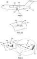
- the figure 1 schematically illustrates a transport aircraft (100) on which a device according to the invention can be implanted.
- a transport aircraft 100
- Such a type of aircraft has a rear body (106) having a large reduction in asymmetrical cross-section of the fuselage (110) upwards.
- This zone with a large reduction in asymmetrical cross-section of the fuselage upwards is called the upsweep zone.
- aerodynamic appendages can be arranged in areas of the fuselage downstream of the wing (108), at the side doors (102) and / or the rear door (104) symmetrically with respect to the longitudinal plane of symmetry of the plane.
- the figure 1 illustrates a side view of the aircraft, but it may have another symmetrical side door where aerodynamic appendages can also be installed.
- the rear appendages are positioned symmetrically on either side of the fuselage.
- the aerodynamic appendages are made of a material similar to that constituting the fuselage of the aircraft or in any material compatible with the rules of the art of aircraft design, capable of withstanding the mechanical stresses. induced by air flows, guaranteeing the rigidity of the device.
- the aerodynamic appendages can be deployed on demand.
- the appendages In a first retracted position, the appendages are folded substantially in the direction of the fuselage. They can be brought into a second deployed position, where they are deployed substantially vertically with respect to the surface of the fuselage.
- the appendages In an initial flight phase, the appendages are preferably in the folded position, then deployed during the duration of the aerolargage operations.
- the appendages can be retracted again after the end of the drop, thus making it possible to control the fuel consumption or the noise emitted during the entire duration of the flight.
- the figure 2a illustrates an aerodynamic appendage (200) in retracted mode positioned on the fuselage (106) of an airplane.
- the appendages are embedded in the surface of the fuselage, not obstructing the existing flow, as illustrated by the local air flow lines (210) on the figure 2a .
- the aerodynamic appendages (200) are in the shape of a delta wing, having two substantially perpendicular edges (b, h) one of which, the base 'b' is placed adjacent to the surface of the aircraft and the other of which, the height 'h' is substantially perpendicular to the surface of the aircraft when the appendix is in position fully deployed. This edge of height 'h' may have a smaller angle than that perpendicular to the surface of the aircraft when the appendix is not fully deployed.
- the figure 3 shows an aerodynamic appendage 'VG' (200) in the deployed position on the fuselage (106) of an airplane, according to one embodiment.
- the deployment of an aerodynamic appendage obstructs the local flow lines of the air flow (210) and it is created behind an aerodynamic appendage deployed vortex or vortex structures (212) whose intensity and trajectory are controlled by the shape, the positioning on the fuselage, the degree of deployment and the timing in incidence of the aerodynamic appendages.
- the aerodynamic appendage (200) preferably has a ratio 'b / h' of the order of '2' between its base 'b' (202) and its height 'h' (204).
- the thickness of the aerodynamic appendages VGs is not critical for the efficiency of the device of the invention, and it can be fixed according to dimensioning rules associated with the mechanical strength of these appendages subjected to the wind, under conditions of flight related to their deployment.
- the height 'h' of an aerodynamic appendage is preferably determined relative to the thickness ' ⁇ ' of the local boundary layer in the implantation zone, and fixed at a few tens of percent of this thickness.
- the boundary layer is defined as the interface zone between a body and a surrounding fluid during a relative movement between the two, and as being the zone where the speed d flow is slowed down by the wall. It begins in contact with the surface where the flow speed is practically zero and extends to a distance where the flow speed is substantially equal to that of the free flow, distance giving the thickness ' ⁇ ' of the boundary layer.
- the height 'h' of an aerodynamic appendage VG can be comprised in a range going from approximately 50% to 120% of the thickness ' ⁇ ' of the boundary layer.
- the deployment of an appendage is done by common means making it possible to ensure the robustness of the mechanism, by using for example hydraulic or electro-hydraulic jacks, of type similar to those used for example for the deployment of side deflectors on board airplanes such as an Airbus A400M or a Boeing C17, but having a dimensioning and a power adapted to the wing surface of each of the appendages, which is much lower than that of side deflectors.
- the aerodynamic appendages VGs are located in areas of the fuselage downstream of the wing where the hydraulic and / or electrical easements necessary for the deployment of the appendages are easily accessible, all of which also allows weight savings.
- the deployed appendages can be raised up to an opening of approximately 90 ° relative to the local surface of the fuselage.
- the appendages are adjustable.
- the incidence ' ⁇ ' relative to the local flow lines of the air flow can be adjustable for each appendix.
- the angle of incidence can be adjusted via a hydraulic, electric, electro-hydraulic or even electromechanical rotation device (not shown) around the axis of the jack used for the deployment of the appendix, and controlled on demand by the personnel on-board, from a command interface, or automatically by a PLC operating in closed loop as shown later with reference to the figure 6 .
- each of the appendices can be refined as a function of the local flow lines of the flow, as a function of the type of aircraft considered in the mission configuration. It should be noted that the local flux lines are determined beforehand during the development of the aircraft, by means of numerical simulations, wind tunnel tests or tests. in flight.
- the Figures 4a and 4b show two embodiments of the device of the invention particularly suitable for the paratrooper release by side door.
- the device is composed of a pair of aerodynamic appendages (402, 404) positioned on the fuselage (106), upstream from the side door (102), for each side door of the aircraft.
- the coupling created between the two aerodynamic appendages, by their geometry and their positioning, produces controlled vortex layers which will interact with the upsweep vortices to attenuate its intensity and modify its trajectory.
- the two vortex-generating appendages are positioned at approximately 1/3 of the fuselage height for the first appendage (402) and at approximately 2/3 of the fuselage height for the second appendage (404). each side of the fuselage symmetrically.
- the vertical positioning can be slightly adapted according to the layout constraints depending on the type of aircraft, without penalizing the efficiency of the device.
- the vertical spacing between the two aerodynamic appendages of a pair is calculated to be of the order of twice the height 'h' of the appendix VG.
- variants with a reasonable tolerance are applicable to this value.
- the aerodynamic appendages are in a preferred embodiment, located at a distance 'd PT ' from the side door, distance defined as being of the order of 1 to 5 times the height 'h' of the appendages.
- the figure 5 illustrates an embodiment of the device of the invention particularly suitable for dropping by door and / or rear ramp (104).
- the device is composed of a plurality of aerodynamic appendages (502-1 to 502-n) positioned in a ramp in a longitudinal direction of the fuselage (106) and regularly spaced from each other.
- the distance 'd VG ' between two aerodynamic appendages VGs is chosen as equal to approximately twice the height 'h' of the appendix.
- variants with a reasonable tolerance are applicable to this value.
- the plurality of VGs aerodynamic appendages is located throughout the upsweep zone, symmetrically on either side of the fuselage, along the door and / or the rear ramp, on the fixed part of the fuselage, according to an azimuthal position on the fuselage, slightly upstream from the line dividing the flow.
- the dividing line and the local flow lines in the area of the aerodynamic appendage ramps were previously determined during the development of the aircraft, by means of numerical simulations, wind tunnel tests or tests in flight.
- each appendage being deployable on demand, the setting in incidence ' ⁇ ' of each appendage can be adapted relative to the local flow lines.
- the adaptive adjustment in incidence of each of the appendages can be managed by software means in the form of an algorithm taking into account pressure measurements in real time, on points distributed in the rear tip zone of the fuselage. (112), and distributed symmetrically on either side of the plane of symmetry of the aircraft.
- the method (600) for adjusting the incidence is described in figure 6 .
- the method begins (602) by activating the deployment of a VG aerodynamic appendage and its setting in incidence according to an initial reference value (602).
- the initial incidence value is a predefined value before the dropping operations and depends on the aerolargging mission and the type of aircraft.
- the method makes it possible (604) to recover pressure values measured in real time in the rear tip zone of the fuselage (112).
- the pressure measurements can be carried out by known components of the pressure sensor type. It should be noted that the method is described to allow the setting in incidence of a single aerodynamic appendage but that it is applicable for all or part of the appendices implemented. In addition, the timing can have the same value for all the appendages or be fixed to different values.
- the method seeks to maximize the pressure measured in the rear tip zone of the fuselage (112), at the end of the upsweep by varying the timing in incidence of the different appendages (606).
- the method enters into a convergence process (608) which makes it possible to vary the incidence of the appendix VG until reaching the maximized value of pressure.
- a convergence process 608 which makes it possible to vary the incidence of the appendix VG until reaching the maximized value of pressure.
- the convergence step (608) towards the optimal calibration of each of the appendages consists in varying the incidence around the reference calibration value, within a predefined range of variation during a calibration. initial obtained by simulations, in a wind tunnel or during certification tests.
- the pressure measurement step (606) consists of measuring the pressure on the upper surface of each of the appendages VGs and the convergence step (608) consists of varying the incidence to minimize the pressure extrados of the appendix, and block the appendix in the orientation according to the incidence giving the minimized pressure value.
- the ability to robustly adapt the incidence timing of the various aerodynamic appendages guarantees the device of the invention maximum efficiency despite possible variations in the release conditions, such as the speed of the aircraft, the asymmetry of the wind by compared to the airplane, the more or less wide opening of the ramp and the rear door, for example or of the mission conditions, which impose drop rates given as a function of the aircraft, of the flight altitude , the type of material dropped (tonnage, rate of release, etc.), but also fortuitous conditions related to the weather, in the theater of operation not necessarily secure (release not necessarily possible in the axis of the prevailing wind), etc. .
Landscapes
- Engineering & Computer Science (AREA)
- Aviation & Aerospace Engineering (AREA)
- Aerodynamic Tests, Hydrodynamic Tests, Wind Tunnels, And Water Tanks (AREA)
- Tires In General (AREA)
Claims (21)
- Vorrichtung zur Dämpfung der im hinteren Bereich eines Luftfahrzeugs erzeugten Wirbelschleppe (100), wobei das Luftfahrzeug mindestens eine Tragfläche (108) und einem Hinterteil mit einer stark asymmetrischen Abnahme des Querschnitts in Richtung des oberen hinteren Rumpfes, die als "upsweep" bezeichnet ist, wobei die Vorrichtung dazu geeignet ist, in Bezug auf die Längsebene des Luftfahrzeugs (100) stromabwärts von der Tragfläche (108) des Luftfahrzeugs symmetrisch positioniert zu werden, wobei die Vorrichtung mindestens zwei Wirbel erzeugende aerodynamische Anhängsel (200) umfasst, die zum Ausfahren zwischen einer eingefahrenen Stellung, in der die aerodynamischen Anhängsel im Wesentlichen in Richtung des Rumpfes eingezogen sind, und einer ausgefahrenen Stellung geeignet sind, wobei die Vorrichtung dadurch gekennzeichnet ist, dass sie Mittel zur Ausführung folgender Funktionen umfasst:Ausfahren und Ausrichten der mindestens zwei aerodynamischen Anhängsel in einem Einfallswinkel α mit einem vorgegebenen Ausgangswert;Messen des Drucks in einem Bereich des Luftfahrzeugs, das für das Vorhandensein von Wirbel erzeugenden Strukturen repräsentativ ist, undVerstellen des Einfallwinkels der mindestens zwei aerodynamischen Anhängsel in Abhängigkeit des gemessenen Drucks, wobei die ausgefahrene verstellte Stellung die Erzeugung von Wirbelstrukturen mit einer Intensität und Flugbahn ermöglicht, die das lokale Druckfeld modifizieren, um mit der Wirbelschleppe in Wechselwirkung zu treten, um sie zu dämpfen und um die Wirbelschleppen von der Längsebene des Luftfahrzeugs zu entfernen.
- Vorrichtung nach Anspruch 1, wobei jedes aerodynamische Anhängsel in ausgefahrener Stellung in einem Einfallswinkel α orientiert ist, dessen Ausgangswert in Bezug auf die lokalen Strömungslinien (210) der Strömung, die auf das aerodynamische Anhängsel einwirken, definiert wird.
- Vorrichtung nach Anspruch 2, wobei der Einfallswinkel α zwischen -20 ° und +30 ° liegt.
- Vorrichtung nach Anspruch 2 oder 3, umfassend hydraulische oder elektrische oder elektrohydraulische oder elektromechanische Mittel, die es ermöglichen, den Einfallswinkel α der aerodynamischen Anhängsel in ausgefahrener Stellung zu variieren.
- Vorrichtung nach einem der Ansprüche 1 bis 4, umfassend hydraulische oder elektrische oder elektrohydraulische oder elektromechanische Mittel, die es ermöglichen, die aerodynamischen Anhängsel von einer Stellung in eine andere zu versetzen.
- Vorrichtung nach einem der Ansprüche 1 bis 5, wobei die aerodynamischen Anhängsel im Wesentlichen deltaflügelförmig sind und zwei im Wesentlichen rechtwinklig zueinander (b, h) angeordnete Kanten (202, 204), von denen eine, die die Basis b darstellt, an die Oberfläche des Luftfahrzeugs angrenzend angeordnet ist, und die andere, die die Höhe h darstellt, in einem rechten Winkel zur Oberfläche des Luftfahrzeugs steht, wenn sich das Anhängsel in voll ausgefahrener Stellung befindet.
- Vorrichtung nach Anspruch 6, wobei das Verhältnis b/h zwischen Basis und Höhe der beiden Kanten (202, 204) des aerodynamischen Anhängsels in der Größenordnung von zwei liegt.
- Vorrichtung nach Anspruch 6 oder 7, wobei die Höhe 'h' eines aerodynamischen Anhängsels in einem Bereich von etwa 50 - 120 % einer vorgegebenen Dicke δ der Grenzschicht liegt.
- Vorrichtung nach einem der Ansprüche 1 bis 8, wobei die aerodynamischen Anhnängsel aus einem Material bestehen, die analog dem des Rumpfes des Luftfahrzeugs ist.
- Vorrichtung nach einem der Ansprüche 1 bis 9, ferner umfassend Mittel zur Steuerung des Ausfahrens der mindestens zwei aerodynamischen Anhängsel und der Orientierung jedes der mindestens zwei Anhängsel.
- Luftfahrzeug (100) mit einer Tragfläche (108) mit einem Hinterteil (106), das eine asymmetrische Abnahme des Querschnitts des hinteren Rumpfes (110) aufweist, wobei das Luftfahrzeug mindestens eine Vorrichtung nach einem der Ansprüche 1 bis 10 aufweist, die in Bezug auf die Längsebene des Luftfahrzeugs symmetrisch stromabwärts von der Tragfläche des Luftfahrzeugs angeordnet ist.
- Luftfahrzeug nach Anspruch 11, umfassend mindestens eine Seitentür (102) und mindestens eine Vorrichtung (402, 404), die stromaufwärts von der Seitentür und in deren Nähe positioniert ist.
- Luftfahrzeug nach Anspruch 11 oder 12, wobei die mindestens eine Vorrichtung ein erstes aerodynamisches Anhängsel, das in etwa 1/3 der Höhe des Rumpfes angeordnet ist, und ein zweites aerodynamisches Anhängsel, das in etwa 2/3 der Höhe des Rumpfes angeordnet ist, umfasst.
- Luftfahrzeug (100) mit einer Tragfläche (108), die ein Hinterteil (106) aufweist, dessen Querschnitt in Richtung des oberen hinteren Rumpfes (110) asymmetrisch abnimmt, und mindestens eine Hintertür und/oder - rampe (104), um Gegenstände durch die Hintertür und/oder -rampe abwerfen zu können, wobei das Lutfahrzeug mindestens eine Vorrichtung nach einem der Ansprüche 1 bis 10 umfasst, wobei die mindestens eine Vorrichtung am hinteren Rumpf entlang des Hinterteils, beiderseits des Luftfahrzeugs entlang der Hintertür und/oder -rampe, auf dem ortsfesten Teil des Rumpfes, in einer Azimutstellung, die leicht stromaufwärts von der Strömungstrennlinie liegt, angeordnet ist.
- Luftfahrzeug nach Anspruch 14, wobei die mindestens eine Vorrichtung aus einer Mehrzahl aerodynamischer Anhängsel (502-i) besteht, die im Wesentlichen in Längsrichtung des Rumpfes ausgerichtet sind.
- Luftfahrzeug nach Anspruch 15, wobei die aerodynamischen Anhängsel regelmäßig voneinander beabstandet sind.
- Verfahren zur Dämpfung der Wirbelschleppe, die von einem Luftfahrzeug mit Tragfläche und einem Hinterteil mit einer in Richtung des oberen hinteren Rumpfes asymmetrisch abnehmenden Querschnitt erzeugt wird, wobei das Luftfahrzeug eine Vorrichtung zur Wirbelschleppendämpfung nach einem der Ansprüche 1 bis 10 umfasst, wobei das Verfahren die Schritte umfasst:Ausfahren und Ausrichten (602) der mindestens zwei aerodynamischen Anhängsel der Vorrichtung in einem Einfallswinkel mit einem vorgegebenen Ausgangswert;Messen (604) des Drucks im Bereich des Luftfahrzeugs, das für das Vorhandensein von Wirbel erzeugenden Strukturen repräsentativ ist, undVerstellen (610) des Einfallwinkels der aerodynamischen Anhängsel in Abhängigkeit des gemessenen Drucks.
- Verfahren nach Anspruch 17, wobei das Verstellen des Einfallswinkels darin besteht, die aerodynamischen Anhängsel gemäß dem Einfall, in dem der gemessene Druck maximiert ist, zu blockieren.
- Verfahren nach Anspruch 17, wobei das Messen des Drucks darin besteht, den Druck auf der Oberseite der Anhängsel zu messen, und das Verstellen des Einfallswinkels die Schritte (606, 608) umfasst:Variieren des Einfallswinkels der aerodynamischen Anhängsel;Messen des Drucks auf der Oberseite der aerodynamischen Anhängsel für eine bestimmte Stellung der aerodynamischen Anhängsel undBlockieren der aerodynamischen Anhängsel gemäß dem Einfall, in dem der gemessene Druck minimiert ist.
- Computerprogrammprodukt, wobei das Computerprogramm Code-Befehle umfasst, die bei Ausführung des Programms auf einem Computer die Ausführung der Schritte des Verfahrens nach einem der Ansprüche 17 bis 19 ermöglichen.
- Informationsspeichermedium, das entfernbar oder nicht-entfernbar ist, das vollständig oder zum Teil von einem Computer oder Mikroprozessor abgelesen werden kann und Computerprogrammbefehle zur Ausführung jedes der Schritte des Verfahrens nach einem der Ansprüche 17 bis 19 umfasst.
Applications Claiming Priority (2)
| Application Number | Priority Date | Filing Date | Title |
|---|---|---|---|
| FR1652008A FR3048674B1 (fr) | 2016-03-10 | 2016-03-10 | Dispositif d'attenuation de sillage tourbillonnaire |
| PCT/EP2017/055299 WO2017153393A1 (fr) | 2016-03-10 | 2017-03-07 | Dispositif d'attenuation de sillage tourbillonnaire |
Publications (2)
| Publication Number | Publication Date |
|---|---|
| EP3426554A1 EP3426554A1 (de) | 2019-01-16 |
| EP3426554B1 true EP3426554B1 (de) | 2020-04-22 |
Family
ID=56611312
Family Applications (1)
| Application Number | Title | Priority Date | Filing Date |
|---|---|---|---|
| EP17708540.4A Active EP3426554B1 (de) | 2016-03-10 | 2017-03-07 | Vorrichtung zur wirbelwalzendämpfung |
Country Status (5)
| Country | Link |
|---|---|
| US (1) | US20200298957A1 (de) |
| EP (1) | EP3426554B1 (de) |
| ES (1) | ES2803356T3 (de) |
| FR (1) | FR3048674B1 (de) |
| WO (1) | WO2017153393A1 (de) |
Family Cites Families (7)
| Publication number | Priority date | Publication date | Assignee | Title |
|---|---|---|---|---|
| US4165849A (en) * | 1977-12-14 | 1979-08-28 | Anthony Fox | Combination air brake and engine shield for aircraft |
| US4739957A (en) * | 1986-05-08 | 1988-04-26 | Advanced Aerodynamic Concepts, Inc. | Strake fence flap |
| US5437419A (en) * | 1992-11-06 | 1995-08-01 | The United States Of America As Represented By The United States National Aeronautics And Space Administration | Rotorcraft blade-vortex interaction controller |
| JPH08230793A (ja) * | 1995-02-23 | 1996-09-10 | Mitsubishi Heavy Ind Ltd | 航空機 |
| US7070146B2 (en) * | 2003-08-29 | 2006-07-04 | Supersonic Aerospace International, Llc | Aircraft thickness/camber control device for low sonic boom |
| WO2011002309A1 (en) * | 2009-06-30 | 2011-01-06 | Blue Sky Ventures | Flying, gliding and/or airdrop craft |
| NL2008049C2 (nl) * | 2011-12-28 | 2013-07-01 | Jan Louis Kroes | Verkeersvliegtuig of vliegsimulator, verstelbaar romproer, computerprogrammaproduct en werkwijze. |
-
2016
- 2016-03-10 FR FR1652008A patent/FR3048674B1/fr not_active Expired - Fee Related
-
2017
- 2017-03-07 EP EP17708540.4A patent/EP3426554B1/de active Active
- 2017-03-07 US US16/083,269 patent/US20200298957A1/en not_active Abandoned
- 2017-03-07 ES ES17708540T patent/ES2803356T3/es active Active
- 2017-03-07 WO PCT/EP2017/055299 patent/WO2017153393A1/fr not_active Ceased
Non-Patent Citations (1)
| Title |
|---|
| None * |
Also Published As
| Publication number | Publication date |
|---|---|
| EP3426554A1 (de) | 2019-01-16 |
| ES2803356T3 (es) | 2021-01-26 |
| WO2017153393A1 (fr) | 2017-09-14 |
| FR3048674A1 (fr) | 2017-09-15 |
| US20200298957A1 (en) | 2020-09-24 |
| FR3048674B1 (fr) | 2020-01-03 |
Similar Documents
| Publication | Publication Date | Title |
|---|---|---|
| EP2234885B1 (de) | Optimierte konfiguration von triebwerken für flugzeuge | |
| EP1456081A1 (de) | Zylindrische flügelspitze mit schraubenförmigem schlitz | |
| EP1223491B1 (de) | System zur automatischen Steuerung von Hochauftriebsklappen eines Flugzeugs während des Starts | |
| EP1768899B1 (de) | Verfahren und vorrichtung zur verbesserung der manövrierfähigkeit eines flugzeugs während der anflugphase vor der landung gefolgt von dem abfangen | |
| EP1568605A1 (de) | Verfahren und Vorrichtung zum Optimiern des Spoilerausschlags eines Flugzeuges während des Fluges | |
| US5037044A (en) | Aerodynamic or hydrodynamic surfaces | |
| FR3037316A1 (fr) | Dispositif volant sans pilote aero-largable | |
| WO2021123540A1 (fr) | Aéronef à propulsion électrique comportant une aile centrale et deux ailes latérales mobiles en rotation | |
| CA3138605A1 (fr) | Groupe de poussee pour dispositif de propulsion et dispositif de propulsion associe | |
| US3984070A (en) | Wingtip vortex dissipator for aircraft | |
| US20110049305A1 (en) | Improved slat configuration for fixed-wing aircraft | |
| Bromfield et al. | Loss of control in flight accident case study: icing-related tailplane stall | |
| EP3426554B1 (de) | Vorrichtung zur wirbelwalzendämpfung | |
| WO2009130413A1 (fr) | Procede pour la determination de la vitesse de sortie d'effet de sol d'un aeronef | |
| WO2020201644A2 (fr) | Appareil pour la navigation aérienne et ses dispositifs | |
| EP2981461B1 (de) | Vorrichtung zur steuerung der geschwindigkeit eines raumfahrzeugs während des übergangs von einer raumfahrtphase zu einer flugphase sowie entsprechendes übergangsverfahren | |
| FR2942455A1 (fr) | Dispositif de securite pour un aeronef convertible bihelice a rotation d'assiette | |
| WO2009133268A1 (fr) | Procédé pour la réduction exceptionnelle de la course d'envol d'un aéronef | |
| Piancastelli et al. | Optimized parachute recovery systems for remote piloted aerial systems | |
| FR3009541A1 (fr) | Ensemble d'avions classiques personnalises et d'avions sans ailes equipes d'ailerons recuperateurs d'air et d'un bouclier de protection du fuselage | |
| Thomas et al. | Global Flyer Jet Drag Chute System | |
| FR3113399A1 (fr) | Dispositif aérodynamique pour aéronef et aéronef muni d’un tel dispositif | |
| Brown et al. | Survey of jet transport incident/accidents with pitch-rate induced abrupt wing stalling near the ground | |
| FR2681833A1 (fr) | Systeme hypersustentateur facilitant les decollages et les atterrissages des mobiles aeriens. | |
| Hamid et al. | Flow field disturbance due to inflight NASA DC-8 inboard thrust reverser deployment |
Legal Events
| Date | Code | Title | Description |
|---|---|---|---|
| STAA | Information on the status of an ep patent application or granted ep patent |
Free format text: STATUS: UNKNOWN |
|
| STAA | Information on the status of an ep patent application or granted ep patent |
Free format text: STATUS: THE INTERNATIONAL PUBLICATION HAS BEEN MADE |
|
| PUAI | Public reference made under article 153(3) epc to a published international application that has entered the european phase |
Free format text: ORIGINAL CODE: 0009012 |
|
| STAA | Information on the status of an ep patent application or granted ep patent |
Free format text: STATUS: REQUEST FOR EXAMINATION WAS MADE |
|
| 17P | Request for examination filed |
Effective date: 20180904 |
|
| AK | Designated contracting states |
Kind code of ref document: A1 Designated state(s): AL AT BE BG CH CY CZ DE DK EE ES FI FR GB GR HR HU IE IS IT LI LT LU LV MC MK MT NL NO PL PT RO RS SE SI SK SM TR |
|
| AX | Request for extension of the european patent |
Extension state: BA ME |
|
| DAV | Request for validation of the european patent (deleted) | ||
| DAX | Request for extension of the european patent (deleted) | ||
| GRAP | Despatch of communication of intention to grant a patent |
Free format text: ORIGINAL CODE: EPIDOSNIGR1 |
|
| STAA | Information on the status of an ep patent application or granted ep patent |
Free format text: STATUS: GRANT OF PATENT IS INTENDED |
|
| INTG | Intention to grant announced |
Effective date: 20191113 |
|
| GRAS | Grant fee paid |
Free format text: ORIGINAL CODE: EPIDOSNIGR3 |
|
| GRAA | (expected) grant |
Free format text: ORIGINAL CODE: 0009210 |
|
| STAA | Information on the status of an ep patent application or granted ep patent |
Free format text: STATUS: THE PATENT HAS BEEN GRANTED |
|
| AK | Designated contracting states |
Kind code of ref document: B1 Designated state(s): AL AT BE BG CH CY CZ DE DK EE ES FI FR GB GR HR HU IE IS IT LI LT LU LV MC MK MT NL NO PL PT RO RS SE SI SK SM TR |
|
| REG | Reference to a national code |
Ref country code: CH Ref legal event code: EP |
|
| REG | Reference to a national code |
Ref country code: DE Ref legal event code: R096 Ref document number: 602017015187 Country of ref document: DE |
|
| REG | Reference to a national code |
Ref country code: IE Ref legal event code: FG4D Free format text: LANGUAGE OF EP DOCUMENT: FRENCH |
|
| REG | Reference to a national code |
Ref country code: AT Ref legal event code: REF Ref document number: 1259739 Country of ref document: AT Kind code of ref document: T Effective date: 20200515 |
|
| REG | Reference to a national code |
Ref country code: LT Ref legal event code: MG4D |
|
| REG | Reference to a national code |
Ref country code: NL Ref legal event code: MP Effective date: 20200422 |
|
| PG25 | Lapsed in a contracting state [announced via postgrant information from national office to epo] |
Ref country code: NL Free format text: LAPSE BECAUSE OF FAILURE TO SUBMIT A TRANSLATION OF THE DESCRIPTION OR TO PAY THE FEE WITHIN THE PRESCRIBED TIME-LIMIT Effective date: 20200422 Ref country code: SE Free format text: LAPSE BECAUSE OF FAILURE TO SUBMIT A TRANSLATION OF THE DESCRIPTION OR TO PAY THE FEE WITHIN THE PRESCRIBED TIME-LIMIT Effective date: 20200422 Ref country code: PT Free format text: LAPSE BECAUSE OF FAILURE TO SUBMIT A TRANSLATION OF THE DESCRIPTION OR TO PAY THE FEE WITHIN THE PRESCRIBED TIME-LIMIT Effective date: 20200824 Ref country code: LT Free format text: LAPSE BECAUSE OF FAILURE TO SUBMIT A TRANSLATION OF THE DESCRIPTION OR TO PAY THE FEE WITHIN THE PRESCRIBED TIME-LIMIT Effective date: 20200422 Ref country code: IS Free format text: LAPSE BECAUSE OF FAILURE TO SUBMIT A TRANSLATION OF THE DESCRIPTION OR TO PAY THE FEE WITHIN THE PRESCRIBED TIME-LIMIT Effective date: 20200822 Ref country code: FI Free format text: LAPSE BECAUSE OF FAILURE TO SUBMIT A TRANSLATION OF THE DESCRIPTION OR TO PAY THE FEE WITHIN THE PRESCRIBED TIME-LIMIT Effective date: 20200422 Ref country code: GR Free format text: LAPSE BECAUSE OF FAILURE TO SUBMIT A TRANSLATION OF THE DESCRIPTION OR TO PAY THE FEE WITHIN THE PRESCRIBED TIME-LIMIT Effective date: 20200723 Ref country code: NO Free format text: LAPSE BECAUSE OF FAILURE TO SUBMIT A TRANSLATION OF THE DESCRIPTION OR TO PAY THE FEE WITHIN THE PRESCRIBED TIME-LIMIT Effective date: 20200722 |
|
| REG | Reference to a national code |
Ref country code: AT Ref legal event code: MK05 Ref document number: 1259739 Country of ref document: AT Kind code of ref document: T Effective date: 20200422 |
|
| PG25 | Lapsed in a contracting state [announced via postgrant information from national office to epo] |
Ref country code: LV Free format text: LAPSE BECAUSE OF FAILURE TO SUBMIT A TRANSLATION OF THE DESCRIPTION OR TO PAY THE FEE WITHIN THE PRESCRIBED TIME-LIMIT Effective date: 20200422 Ref country code: RS Free format text: LAPSE BECAUSE OF FAILURE TO SUBMIT A TRANSLATION OF THE DESCRIPTION OR TO PAY THE FEE WITHIN THE PRESCRIBED TIME-LIMIT Effective date: 20200422 Ref country code: BG Free format text: LAPSE BECAUSE OF FAILURE TO SUBMIT A TRANSLATION OF THE DESCRIPTION OR TO PAY THE FEE WITHIN THE PRESCRIBED TIME-LIMIT Effective date: 20200722 Ref country code: HR Free format text: LAPSE BECAUSE OF FAILURE TO SUBMIT A TRANSLATION OF THE DESCRIPTION OR TO PAY THE FEE WITHIN THE PRESCRIBED TIME-LIMIT Effective date: 20200422 |
|
| PG25 | Lapsed in a contracting state [announced via postgrant information from national office to epo] |
Ref country code: AL Free format text: LAPSE BECAUSE OF FAILURE TO SUBMIT A TRANSLATION OF THE DESCRIPTION OR TO PAY THE FEE WITHIN THE PRESCRIBED TIME-LIMIT Effective date: 20200422 |
|
| REG | Reference to a national code |
Ref country code: DE Ref legal event code: R097 Ref document number: 602017015187 Country of ref document: DE |
|
| REG | Reference to a national code |
Ref country code: ES Ref legal event code: FG2A Ref document number: 2803356 Country of ref document: ES Kind code of ref document: T3 Effective date: 20210126 |
|
| PG25 | Lapsed in a contracting state [announced via postgrant information from national office to epo] |
Ref country code: CZ Free format text: LAPSE BECAUSE OF FAILURE TO SUBMIT A TRANSLATION OF THE DESCRIPTION OR TO PAY THE FEE WITHIN THE PRESCRIBED TIME-LIMIT Effective date: 20200422 Ref country code: IT Free format text: LAPSE BECAUSE OF FAILURE TO SUBMIT A TRANSLATION OF THE DESCRIPTION OR TO PAY THE FEE WITHIN THE PRESCRIBED TIME-LIMIT Effective date: 20200422 Ref country code: SM Free format text: LAPSE BECAUSE OF FAILURE TO SUBMIT A TRANSLATION OF THE DESCRIPTION OR TO PAY THE FEE WITHIN THE PRESCRIBED TIME-LIMIT Effective date: 20200422 Ref country code: EE Free format text: LAPSE BECAUSE OF FAILURE TO SUBMIT A TRANSLATION OF THE DESCRIPTION OR TO PAY THE FEE WITHIN THE PRESCRIBED TIME-LIMIT Effective date: 20200422 Ref country code: RO Free format text: LAPSE BECAUSE OF FAILURE TO SUBMIT A TRANSLATION OF THE DESCRIPTION OR TO PAY THE FEE WITHIN THE PRESCRIBED TIME-LIMIT Effective date: 20200422 Ref country code: DK Free format text: LAPSE BECAUSE OF FAILURE TO SUBMIT A TRANSLATION OF THE DESCRIPTION OR TO PAY THE FEE WITHIN THE PRESCRIBED TIME-LIMIT Effective date: 20200422 Ref country code: AT Free format text: LAPSE BECAUSE OF FAILURE TO SUBMIT A TRANSLATION OF THE DESCRIPTION OR TO PAY THE FEE WITHIN THE PRESCRIBED TIME-LIMIT Effective date: 20200422 |
|
| PG25 | Lapsed in a contracting state [announced via postgrant information from national office to epo] |
Ref country code: SK Free format text: LAPSE BECAUSE OF FAILURE TO SUBMIT A TRANSLATION OF THE DESCRIPTION OR TO PAY THE FEE WITHIN THE PRESCRIBED TIME-LIMIT Effective date: 20200422 Ref country code: PL Free format text: LAPSE BECAUSE OF FAILURE TO SUBMIT A TRANSLATION OF THE DESCRIPTION OR TO PAY THE FEE WITHIN THE PRESCRIBED TIME-LIMIT Effective date: 20200422 |
|
| PLBE | No opposition filed within time limit |
Free format text: ORIGINAL CODE: 0009261 |
|
| STAA | Information on the status of an ep patent application or granted ep patent |
Free format text: STATUS: NO OPPOSITION FILED WITHIN TIME LIMIT |
|
| 26N | No opposition filed |
Effective date: 20210125 |
|
| PG25 | Lapsed in a contracting state [announced via postgrant information from national office to epo] |
Ref country code: SI Free format text: LAPSE BECAUSE OF FAILURE TO SUBMIT A TRANSLATION OF THE DESCRIPTION OR TO PAY THE FEE WITHIN THE PRESCRIBED TIME-LIMIT Effective date: 20200422 |
|
| PG25 | Lapsed in a contracting state [announced via postgrant information from national office to epo] |
Ref country code: MC Free format text: LAPSE BECAUSE OF FAILURE TO SUBMIT A TRANSLATION OF THE DESCRIPTION OR TO PAY THE FEE WITHIN THE PRESCRIBED TIME-LIMIT Effective date: 20200422 |
|
| REG | Reference to a national code |
Ref country code: CH Ref legal event code: PL |
|
| REG | Reference to a national code |
Ref country code: BE Ref legal event code: MM Effective date: 20210331 |
|
| PG25 | Lapsed in a contracting state [announced via postgrant information from national office to epo] |
Ref country code: IE Free format text: LAPSE BECAUSE OF NON-PAYMENT OF DUE FEES Effective date: 20210307 Ref country code: CH Free format text: LAPSE BECAUSE OF NON-PAYMENT OF DUE FEES Effective date: 20210331 Ref country code: LI Free format text: LAPSE BECAUSE OF NON-PAYMENT OF DUE FEES Effective date: 20210331 Ref country code: LU Free format text: LAPSE BECAUSE OF NON-PAYMENT OF DUE FEES Effective date: 20210307 |
|
| PG25 | Lapsed in a contracting state [announced via postgrant information from national office to epo] |
Ref country code: BE Free format text: LAPSE BECAUSE OF NON-PAYMENT OF DUE FEES Effective date: 20210331 |
|
| PG25 | Lapsed in a contracting state [announced via postgrant information from national office to epo] |
Ref country code: CY Free format text: LAPSE BECAUSE OF FAILURE TO SUBMIT A TRANSLATION OF THE DESCRIPTION OR TO PAY THE FEE WITHIN THE PRESCRIBED TIME-LIMIT Effective date: 20200422 |
|
| PG25 | Lapsed in a contracting state [announced via postgrant information from national office to epo] |
Ref country code: HU Free format text: LAPSE BECAUSE OF FAILURE TO SUBMIT A TRANSLATION OF THE DESCRIPTION OR TO PAY THE FEE WITHIN THE PRESCRIBED TIME-LIMIT; INVALID AB INITIO Effective date: 20170307 |
|
| PG25 | Lapsed in a contracting state [announced via postgrant information from national office to epo] |
Ref country code: MK Free format text: LAPSE BECAUSE OF FAILURE TO SUBMIT A TRANSLATION OF THE DESCRIPTION OR TO PAY THE FEE WITHIN THE PRESCRIBED TIME-LIMIT Effective date: 20200422 |
|
| PG25 | Lapsed in a contracting state [announced via postgrant information from national office to epo] |
Ref country code: TR Free format text: LAPSE BECAUSE OF FAILURE TO SUBMIT A TRANSLATION OF THE DESCRIPTION OR TO PAY THE FEE WITHIN THE PRESCRIBED TIME-LIMIT Effective date: 20200422 |
|
| PG25 | Lapsed in a contracting state [announced via postgrant information from national office to epo] |
Ref country code: MT Free format text: LAPSE BECAUSE OF FAILURE TO SUBMIT A TRANSLATION OF THE DESCRIPTION OR TO PAY THE FEE WITHIN THE PRESCRIBED TIME-LIMIT Effective date: 20200422 |
|
| PGFP | Annual fee paid to national office [announced via postgrant information from national office to epo] |
Ref country code: ES Payment date: 20250414 Year of fee payment: 9 |
|
| PGFP | Annual fee paid to national office [announced via postgrant information from national office to epo] |
Ref country code: GB Payment date: 20260216 Year of fee payment: 10 |
|
| PGFP | Annual fee paid to national office [announced via postgrant information from national office to epo] |
Ref country code: DE Payment date: 20260211 Year of fee payment: 10 |
|
| PGFP | Annual fee paid to national office [announced via postgrant information from national office to epo] |
Ref country code: FR Payment date: 20260209 Year of fee payment: 10 |