EP3425927A1 - Verfahren zum herstellen eines gehäuseteils einer hörvorrichtung, gehäuseteil für eine hörvorrichtung und hörvorrichtung - Google Patents
Verfahren zum herstellen eines gehäuseteils einer hörvorrichtung, gehäuseteil für eine hörvorrichtung und hörvorrichtung Download PDFInfo
- Publication number
- EP3425927A1 EP3425927A1 EP18177395.3A EP18177395A EP3425927A1 EP 3425927 A1 EP3425927 A1 EP 3425927A1 EP 18177395 A EP18177395 A EP 18177395A EP 3425927 A1 EP3425927 A1 EP 3425927A1
- Authority
- EP
- European Patent Office
- Prior art keywords
- housing part
- hearing device
- housing
- wall
- matrix material
- Prior art date
- Legal status (The legal status is an assumption and is not a legal conclusion. Google has not performed a legal analysis and makes no representation as to the accuracy of the status listed.)
- Granted
Links
Images
Classifications
-
- H—ELECTRICITY
- H04—ELECTRIC COMMUNICATION TECHNIQUE
- H04R—LOUDSPEAKERS, MICROPHONES, GRAMOPHONE PICK-UPS OR LIKE ACOUSTIC ELECTROMECHANICAL TRANSDUCERS; ELECTRIC HEARING AIDS; PUBLIC ADDRESS SYSTEMS
- H04R25/00—Electric hearing aids
- H04R25/65—Housing parts, e.g. shells, tips or moulds, or their manufacture
- H04R25/652—Ear tips; Ear moulds
-
- H—ELECTRICITY
- H04—ELECTRIC COMMUNICATION TECHNIQUE
- H04R—LOUDSPEAKERS, MICROPHONES, GRAMOPHONE PICK-UPS OR LIKE ACOUSTIC ELECTROMECHANICAL TRANSDUCERS; ELECTRIC HEARING AIDS; PUBLIC ADDRESS SYSTEMS
- H04R25/00—Electric hearing aids
-
- H—ELECTRICITY
- H04—ELECTRIC COMMUNICATION TECHNIQUE
- H04R—LOUDSPEAKERS, MICROPHONES, GRAMOPHONE PICK-UPS OR LIKE ACOUSTIC ELECTROMECHANICAL TRANSDUCERS; ELECTRIC HEARING AIDS; PUBLIC ADDRESS SYSTEMS
- H04R25/00—Electric hearing aids
- H04R25/65—Housing parts, e.g. shells, tips or moulds, or their manufacture
- H04R25/658—Manufacture of housing parts
-
- H—ELECTRICITY
- H04—ELECTRIC COMMUNICATION TECHNIQUE
- H04R—LOUDSPEAKERS, MICROPHONES, GRAMOPHONE PICK-UPS OR LIKE ACOUSTIC ELECTROMECHANICAL TRANSDUCERS; ELECTRIC HEARING AIDS; PUBLIC ADDRESS SYSTEMS
- H04R2225/00—Details of deaf aids covered by H04R25/00, not provided for in any of its subgroups
- H04R2225/025—In the ear hearing aids [ITE] hearing aids
Definitions
- the invention relates to a method for producing a housing part of a hearing device. Furthermore, the invention relates to such a housing part and further also a hearing device with such a housing part.
- a hearing device usually serves to output acoustic signals to the ear of a wearer of this hearing device.
- a hearing device usually comprises an output transducer, which is usually designed as a loudspeaker (also referred to as “receiver” or “receiver”).
- This output transducer is usually surrounded by a housing part of the hearing device, for example a housing shell or the like, in order to protect the output transducer from environmental influences and / or to allow proper alignment of the output transducer, for example in the ear canal of the wearer of the hearing device.
- Such a hearing device may, for example, be a headset, headphones, so-called wearables, tinnitus maskers or the like.
- hearing devices also serve to supply persons with reduced hearing with (often carrier-specific) amplified and / or filtered acoustic signals in order to at least partially compensate for the present hearing loss.
- a hearing device is also referred to as a hearing aid device or short hearing device.
- the hearing device usually also includes an input transducer, usually in the form of a microphone for detecting ambient noise and a downstream signal processor (also: “controller”) for processing (filtering and / or amplifying) signals generated from the environmental sounds and outputting these processed signals to the output transducer.
- the output transducer can also, depending on the type of hearing loss, be designed as a bone conduction earpiece or cochlear implant for the mechanical or electrical stimulation of the hearing of the wearer.
- hearing aids also different types are also used.
- BTE behind-the-ear hearing aids
- the at least one microphone, the signal processor and an energy source are arranged in a housing (part) to be supported behind the pinna.
- the output transducer can also be arranged in this housing (part) and is connected in this case by means of a sound tube with the ear canal of the wearer.
- the loudspeaker may also be arranged in a separate housing part (often referred to as "earpiece”) and be connected via a signal line to the components arranged in the actual hearing device housing.
- in-the-ear hearing aids are also used which have a housing which is to be supported completely or partially in the auditory canal and contains the electronic components.
- the outer contour of the hearing device is thereby individually adapted to the auditory canal or executed via flexible "plug-like" ear pieces (also known as “Domes”) adaptable to a variety of different auditory canal shapes.
- an impression of the individual auditory canal is usually taken and reproduced for example by means of generative methods (3D printing, stereolithography and the like).
- the thereby formed, also referred to as "Earshell” housing parts are made of a comparatively rigid material. In the event that a high amplification effect of the speaker is required, this must also be stored on flexible damping materials (in particular to reduce a structure-borne sound feedback to the microphone), so usually increases the required space.
- the invention has for its object to provide an improved housing part for a hearing.
- This object is achieved by a method for producing a housing part of a hearing device according to the features of claim 1. Also, this object is achieved by a method for producing a hearing device according to the features of claim 11. Furthermore, this object is achieved by a In addition, the object is achieved by a hearing device with the features of claim 13. Further advantageous and partly inventive embodiments and developments of the invention are set forth in more detail in the dependent claims and the description below.
- the method according to the invention serves to produce a housing part of a hearing device, preferably in the auditory canal of a person (hereinafter referred to as "carrier” for short).
- This housing part serves to receive at least one electronic component of the hearing device in a housing interior.
- a fiber framework for a wall of the housing part which at least partially surrounds the interior of the housing is (preferably initially) made of fibers (alternatively also referred to as "filaments").
- a mechanical property of the wall (preferably to be finished in a later method step) along a reference direction of the housing part is predetermined in a varying manner.
- the wall of the housing part in the intended final production state over its extension along the reference direction has a varying mechanical property.
- the fiber framework in particular for the formation of the wall
- a matrix material at least over part of its longitudinal extension (preferably along the reference direction).
- reference direction is understood here and below as meaning, in particular, a direction along which, in particular, a (top) surface of the housing part which is predetermined by the wall or the fiber structure extends.
- a longitudinal extent of the housing part extends in this reference direction.
- it does not concern the thickness direction of the wall or of the fiber skeleton.
- Particularly preferred - especially in the housing part to be worn in the auditory canal - is in the reference direction to a direction of insertion of the housing part in the ear canal.
- insertion direction is to be understood in particular as the direction along which the housing part, specifically the finished hearing device, is inserted as intended into the auditory canal of the wearer.
- the inventive method advantageously provides a way to reduce the number of required for a hearing device items and save space and installation costs. This is achieved, in particular, by integrating the functions of different structures of conventional hearing devices, in particular of usually individual, separate components, which have different mechanical properties for their respective purposes, into a common component, namely the housing part described above.
- the housing part according to the invention for the hearing device is produced by means of the method described here and below.
- the housing part according to the invention has the resulting from the respective process steps physical characteristics.
- the hearing device according to the invention comprises the housing part described above and thus produced by the method according to the invention.
- the housing part as well as this comprehensive hearing device thus also have the advantages of the method according to the invention.
- a flexibility of the wall is specified as varying in particular as a mechanical property.
- the fiber structure is constructed such that in the intended (end) production state of the housing part, the wall has a specifically varying rigidity (ie different stiffness values).
- This can, for example on a single housing part, regions are created which have increased stiffness (ie increased stiffness value) for holding components (eg further housing parts and / or electronic components), and other regions which due to particularly low rigidity (ie a low stiffness value) For example, allow a particularly pleasant adaptation to the ear canal of the wearer (so can cling to the ear canal).
- the wall therefore has, in the intended final production state, a flexibility varying along the reference direction, in particular the insertion direction.
- a compressibility of the wall is specified as a mechanical property (in addition or as an alternative to flexibility).
- the flexibility of the wall is increasingly predetermined, in particular in the direction of insertion.
- This means that the wall in the finished state has a higher flexibility (or lower rigidity) in the region of its leading end in the insertion direction than at its trailing end in the direction of insertion.
- the course of the flexibility (or even stiffness) can be formed continuously and / or at least one more or less pronounced jump in stiffness (that is to say a step-like change).
- the region with the lowest rigidity or the highest flexibility (hereinafter also referred to as "flexible region”) is preferably designed such that an elastic deformation by hand without special effort is possible.
- the region with the highest rigidity is preferably designed such that such (manual) elastic deformation is not possible or compared to the flexible region only under significantly increased force application and / or only to a negligible degree.
- the fiber structure is constructed varying in its geometric structure and / or its density in order to specify the mechanical properties of the wall.
- the geometric structure are both on the one hand precipitates in external dimensions structural features, such as As the wall thickness, ribs, beads and the like, as well as "internal structural features", understood as in particular an orientation of the fibers within the fiber skeleton.
- the fibers are oriented to accommodate a majority of the forces acting on the wall in use, or alternatively, these forces act across the fibers so that a reinforcing effect is relatively small.
- the density of the fiber skeleton in particular the number of fibers running in a volume element of the fiber skeleton is predetermined differently.
- a particularly crosslinkable elastomer is used as the matrix material.
- the matrix material is thus a material with comparatively high elasticity and flexibility, which is reinforced by the fiber skeleton to locally different stiffness values.
- this elastomer is a silicone (concretely a polyorganosiloxane), rubber, rubber or the like.
- the elastomer used preferably has a sufficiently low viscosity in the uncrosslinked state in order to allow the infiltration of the fiber skeleton, if possible, without the inclusion of air bubbles. To infiltrate the fiber scaffold come process, such.
- the matrix material in particular the elastomer after infiltration, is also cured (i.e., crosslinked).
- thermoplastic elastomer it is also conceivable within the scope of the invention for a thermoplastic elastomer to be used.
- the fiber structure is infiltrated such that the resulting wall closed, ie not open-pored or channel-like, is.
- the wall is thus preferably sealed against the passage of contaminants or moisture.
- the material used for the fibers of the fiber structure is a thermoplastic, in particular a polyamide or a polyether block amide.
- a thermoplastic in particular a polyamide or a polyether block amide.
- other thermoplastics such as polyester, are used.
- the fiber skeleton is constructed by electrospinning.
- a number of fibers are withdrawn under the action of an electric field from a polymer solution and deposited on a counterelectrode, in particular in the form of a type of fleece.
- the fibers formed are deposited in a mold core (also referred to as a "target"), which predetermines the later geometry of the fiber structure.
- the fibers are deposited comparable to a 3D printing process without such a mold core and "stacked" to the fiber structure.
- the variation of the properties of the fiber skeleton is carried out by targeted change of movement and / or movement speed of the mandrel and / or the spinning head (from which the fibers are deducted), the size of the mandrel, a change of the electric field or the like.
- a variation of the framework properties and thus the mechanical properties of the later wall of the housing part - advantageously also individually, d. H. carrier specific - to be set.
- electrospinning it is also possible in a particularly simple manner to set continuous transitions between regions of different flexibility (that is, different stiffness values).
- the fiber structure of a woven and / or non-woven (fiber) semi-finished - ie, in particular from a fabric, scrim, fleece or the like - constructed.
- this additional forming process of these semi-finished products such. B. thermoforming, used.
- the variation of the mechanical properties preferably takes place via the use of different semi-finished products, which vary with one another, for example, in terms of their density, their material thickness and / or their fiber orientation.
- the stiffness course of the wall in comparison to electrospinning usually distinct (ie, in particular recognizable step-like) transitions between regions of different stiffness values.
- an end of the fibrous framework which forms an annular edge around the interior of the housing and which is opposite to the reference direction (that is, trailing in particular in the direction of insertion) is kept free of the matrix material.
- the fibers of the fiber skeleton are free and are not embedded in the matrix material.
- the housing interior is preferably closed at the end or edge of the housing part which is kept free of matrix material with a cover plate - also referred to as "faceplate” in the case of an ITO.
- This cover plate is suitably fastened by means of an adhesive to the wall so that the adhesive penetrates into the fiber framework kept free of the matrix material and thus in addition to an adhesive (cohesive) connection also a claw with the fiber skeleton (and thus additionally also a positive connection) formed with the housing part.
- the invention thus also relates to a method for producing the hearing device with the housing part described above.
- the cover plate is preferably connected in the manner described above with the housing part.
- the invention described above allows - as already described - the formation of a housing part, in particular a hearing aid housing, which has at least partially varying mechanical properties.
- the projecting into the ear canal end of the housing part is particularly flexible, so this on the one hand to nestle against the ear canal and on the other hand - especially for comparatively high required sound levels of the speaker for this also a damped mounting structure (or: storage) offers.
- the housing part produced by the method described above in the thickness direction is the only, the hearing aid components over the ear canal delimiting shell.
- the hearing aid components over the ear canal delimiting shell.
- at least partially a kind of inner housing in the housing part described above Holder of hearing device components is inserted.
- Such an inner housing is, in particular, a "frame part" made of a comparatively rigid plastic, for example a polyamide, an ABS (acrylonitrile-butadiene-styrene copolymer) or comparable plastics.
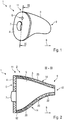
- Fig. 1 is shown as a hearing aid a hearing aid 1, specifically an in-the-ear hearing aid.
- the hearing aid 1 comprises a housing 2, which is formed essentially of a first housing part 3 and a second housing part 4. How out Fig. 2 can be seen forms the first housing part 3 also referred to as "Earshell” and a housing interior 5 circumferentially bounding component.
- the second housing part 4 is also referred to as "faceplate” and forms a Cover plate with which the housing interior 5 is closed on one side against the housing part 3.
- the second housing part 4 has, inter alia, a microphone opening 6 for detecting ambient noise by means of a microphone arranged in the housing interior 5 and a battery compartment door 7 for the reversible mounting and positioning of a hearing aid battery (not shown in detail).
- the hearing device 1 has a tapered outer contour along a reference direction, specifically an insertion direction 8, along which the hearing device 1 is intended to be inserted into an auditory canal of a wearer.
- the first housing part 3 has a (schematically illustrated) sound outlet 10 is discharged through the air in the intended state of wear in the ear canal of the wearer of a arranged in the housing interior speaker 5 airborne sound in the direction of the eardrum.
- the second housing part 4 and the faceplate is placed on the local edge 12 of the first housing part 3 and connected thereto by an adhesive connection.
- the first housing part 3 has in the insertion direction 8, d. H. from the rear end 11 or the edge 12 there, in the direction of the tip end 9, an increasing flexibility, ie decreasing rigidity values.
- the first housing part 3 is designed in the region of the tip end 9 so soft and flexible that it can conform to the contour of the ear canal in this area and at the same time can serve as a damping element for positioned in this area within the housing interior 5 speaker.
- the housing part 3 is designed as a fiber composite component.
- a fiber structure (for the later wall 14) is first constructed from fibers 20.
- a thermoplastic material specifically a polyamide, used.
- the fibers are thereby transported by electrospinning as in Fig. 2 schematically indicated - in the direction of insertion 8 decreasing density, ie concretely deposited with respect to the finished housing part 3 weight and / or volume-related fiber content to the fiber structure on each other.
- the fiber structure and thus the fiber interstices between the fibers 20 are infiltrated with a matrix material, ie filled with wetting of the fibers 20.
- the wall 14 is dense, ie not traversed by air pockets or open spaces (or: "spongy") formed.
- a crosslinkable silicone which is cured after the infiltration of the fiber skeleton, ie crosslinked, is used as the matrix material 22.
- the matrix material 22 thus has a sufficiently low viscosity for the infiltration of the fiber skeleton and a sufficiently low flexibility in the crosslinked state.
- the fiber structure is kept free in the region of the edge 12 in the infiltration of the fiber skeleton with the matrix material 22, so that in this area the fibers 20 are exposed and not embedded in the matrix material 22.
- the second housing part 4 is then glued to the edge 12 by means of an adhesive. The adhesive penetrates into the fiber skeleton which is exposed, thereby forming a connection between the second housing part 4 and the first housing part 3 that is both materially and positively locking.
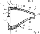
- Fig. 3 is a further embodiment shown in more detail.
- the variation of the rigidity or flexibility of the first housing part 3 or its wall 14 along the insertion direction 8 takes place here via a combination of the geometric structure of the fiber skeleton and by the above-described variation of the fiber content of the fibers 20 along the insertion direction 8.
- the Housing part 3 a seen in the insertion direction 8 gradually decreasing wall thickness.
- the fiber content of the fibers 20 takes analogous to that of Fig. 2 described embodiment also in the direction of the tip end 9 from.
- the fibers 20 are not arranged by means of electrospinning, but are formed as part of at least two semi-finished fiber products of different types.
- the first housing part 3 at least two with respect to the flexibility stepwise separated from each other areas.
- the different semifinished fiber products are draped onto a mandrel (for example, wound or otherwise placed) and / or reshaped by means of a mandrel 5 imaging the mandrel interior, for example by thermoforming (also referred to as deep drawing).
Landscapes
- Engineering & Computer Science (AREA)
- Manufacturing & Machinery (AREA)
- Health & Medical Sciences (AREA)
- General Health & Medical Sciences (AREA)
- Neurosurgery (AREA)
- Otolaryngology (AREA)
- Physics & Mathematics (AREA)
- Acoustics & Sound (AREA)
- Signal Processing (AREA)
- Prostheses (AREA)
- Nonwoven Fabrics (AREA)
Abstract
Description
- Die Erfindung betrifft ein Verfahren zum Herstellen eines Gehäuseteils einer Hörvorrichtung. Des Weiteren betrifft die Erfindung ein solches Gehäuseteil sowie ferner auch eine Hörvorrichtung mit einem solchen Gehäuseteil.
- Eine Hörvorrichtung dient üblicherweise zur Ausgabe von akustischen Signalen an das Ohr eines Trägers dieser Hörvorrichtung. Dazu umfasst eine solche Hörvorrichtung üblicherweise einen Ausgabewandler, der meist als Lautsprecher (auch als "Receiver" oder "Hörer" bezeichnet) ausgebildet ist. Dieser Ausgabewandler ist üblicherweise von einem Gehäuseteil der Hörvorrichtung, beispielsweise einer Gehäuseschale oder dergleichen, umgeben, um den Ausgabewandler vor Umwelteinflüssen zu schützen und/oder eine bestimmungsgemäße Ausrichtung des Ausgabewandlers beispielsweise im Gehörgang des Trägers der Hörvorrichtung zu ermöglichen. Bei einer solchen Hörvorrichtung kann es sich beispielsweise um ein Headset, Kopfhörer, sogenannte (in ear) wearables, Tinnitusmaskers oder dergleichen handeln.
- Häufig dienen Hörvorrichtungen aber auch zur Versorgung von Personen mit vermindertem Hörvermögen mit (häufig trägerspezifisch) verstärkten und/oder gefilterten akustischen Signalen, um die vorliegende Hörminderung wenigstens teilweise auszugleichen. In diesem Fall wird eine solche Hörvorrichtung auch als Hörhilfegerät oder kurz Hörgerät bezeichnet. Insbesondere im Fall eines Hörgeräts umfasst die Hörvorrichtung üblicherweise auch einen Eingangswandler, meist in Form eines Mikrofons zur Erfassung von Umgebungsgeräuschen sowie einen nachgeschalteten Signalprozessor (auch: "Controller") zur Verarbeitung (Filterung und/oder Verstärkung) von aus den Umgebungsgeräuschen erzeugten Signalen und zur Ausgabe dieser verarbeiteten Signale an den Ausgabewandler. Bei Hörgeräten kann der Ausgabewandler außerdem auch -je nach Art der Hörminderung - als Knochenleitungshörer oder Cochlea-Implantat zur mechanischen bzw. elektrischen Stimulation des Gehörs des Trägers ausgebildet sein.
- Bei Hörgeräten kommen ferner auch unterschiedliche Bauformen zum Einsatz. Bei sogenannten Hinter-dem-Ohr-Hörgeräten (kurz als "HdO" bezeichnet) sind das wenigstens eine Mikrofon, der Signalprozessor sowie eine Energiequelle in einem hinter der Ohrmuschel zu tragenden Gehäuse(-teil) angeordnet. Der Ausgabewandler kann dabei ebenfalls in diesem Gehäuse(-teil) angeordnet sein und wird in diesem Fall mittels eines Schallschlauchs mit dem Gehörgang des Trägers verbunden. Alternativ kann der Lautsprecher auch in einem eigenen Gehäuseteil (oft als "Ohrstück" bezeichnet) angeordnet sein und über eine Signalleitung mit den im eigentlichen Hörgerätegehäuse angeordneten Komponenten verbunden sein. Des Weiteren kommen auch sogenannte In-dem-Ohr-Hörgeräte (kurz: "IdO") zum Einsatz, die ein ganz oder teilweise im Gehörgang zu tragendes, die elektronischen Komponenten enthaltendes Gehäuse aufweisen. Je nach Ausführung eines solchen IdO wird die Außenkontur des Hörgeräts dabei individuell an den Gehörgang angepasst oder über flexible "stöpselartige" Ohrstücke (auch als "Domes" bezeichnet) an eine Vielzahl von unterschiedlichen Gehörgangformen anpassbar ausgeführt. Zur individuellen Anpassung wird meist ein Abdruck des individuellen Gehörgangs genommen und dieser beispielsweise mittels generativer Verfahren (3D-Druck, Stereolithografie und dergleichen) nachgebaut. Die dabei ausgeformten, auch als "Earshell" bezeichneten Gehäuseteile sind dabei aus einem vergleichsweise steifen Material gefertigt. Für den Fall, dass eine hohe Verstärkungswirkung des Lautsprechers erforderlich ist, muss dieser zusätzlich über flexible Dämpfungsmaterialien gelagert werden (insbesondere um eine körperschallbedingte Rückkopplung auf das Mikrofon zu verringern), sodass sich meist der erforderliche Bauraum vergrößert.
- Der Erfindung liegt die Aufgabe zugrunde, ein verbessertes Gehäuseteil für eine Hörvorrichtung zu ermöglichen.
- Diese Aufgabe wird erfindungsgemäß gelöst durch ein Verfahren zum Herstellen eines Gehäuseteils einer Hörvorrichtung gemäß den Merkmalen nach Anspruch 1. Ebenfalls wird diese Aufgabe erfindungsgemäß gelöst durch ein Verfahren zum Herstellen einer Hörvorrichtung gemäß den Merkmalen nach Anspruch 11. Des Weiteren wird diese Aufgabe erfindungsgemäß gelöst durch ein Gehäuseteil für eine Hörvorrichtung mit den Merkmalen des Anspruchs 12. Außerdem wird die Aufgabe erfindungsgemäß gelöst durch eine Hörvorrichtung mit den Merkmalen des Anspruchs 13. Weitere vorteilhafte und teils für sich erfinderische Ausführungsformen und Weiterbildungen der Erfindung werden in den Unteransprüchen und der nachfolgenden Beschreibung näher dargelegt.
- Das erfindungsgemäße Verfahren dient zum Herstellen eines - vorzugsweise im Gehörgang einer Person (im Folgenden kurz als "Träger" bezeichnet) zu tragenden - Gehäuseteils einer Hörvorrichtung. Dieses Gehäuseteil dient dabei zur Aufnahme wenigstens einer elektronischen Komponente der Hörvorrichtung in einem Gehäuseinnenraum. Verfahrensgemäß wird dabei (vorzugsweise zunächst) aus Fasern (alternativ auch als "Filamente" bezeichnet) ein Fasergerüst für eine den Gehäuseinnenraum zumindest teilweise umgrenzende Wandung des Gehäuseteils aufgebaut. Mittels der Fasern wird dabei eine mechanische Eigenschaft der (vorzugsweise in einem späteren Verfahrensschritt fertigzustellenden) Wandung entlang einer Referenzrichtung des Gehäuseteils variierend vorgegeben. Das heißt, dass die Wandung des Gehäuseteils im bestimmungsgemäßen Endfertigungszustand über ihre Erstreckung entlang der Referenzrichtung eine variierende mechanische Eigenschaft aufweist. Anschließend wird das Fasergerüst (insbesondere zur Ausbildung der Wandung) zumindest über einen Teil seiner (vorzugsweise entlang der Referenzrichtung verlaufenden) Längserstreckung mit einem Matrixmaterial infiltriert.
- Unter dem Begriff "Referenzrichtung" wird hier und im Folgenden insbesondere eine Richtung verstanden, entlang derer sich insbesondere eine von der Wandung bzw. dem Fasergerüst vorgegebene (Ober-)Fläche des Gehäuseteils erstreckt. Vorzugsweise verläuft eine Längserstreckung des Gehäuseteils dabei in dieser Referenzrichtung. Es handelt sich dabei also insbesondere nicht um die Dickenrichtung der Wandung bzw. des Fasergerüsts. Besonders bevorzugt - insbesondere bei dem im Gehörgang zu tragenden Gehäuseteil - handelt es sich bei der Referenzrichtung um eine Einschubrichtung des Gehäuseteils in den Gehörgang. In diesem Fall ist "Einschubrichtung" insbesondere als die Richtung zu verstehen, entlang derer das Gehäuseteil, konkret die fertiggestellte Hörvorrichtung, bestimmungsgemäß in den Gehörgang des Trägers eingeführt wird.
- Das erfindungsgemäße Verfahren schafft vorteilhafterweise eine Möglichkeit, die Anzahl der für eine Hörvorrichtung erforderlichen Einzelteile zu reduzieren sowie Bauraum und Montageaufwand einzusparen. Dies wird insbesondere erreicht, in-dem die Funktionen unterschiedlicher Strukturen gewöhnlicher Hörvorrichtungen, insbesondere üblicherweise einzelner, separater Bauteile, die für ihre jeweilige Zweckerfüllung voneinander abweichende mechanische Eigenschaften aufweisen, in ein gemeinsames Bauteil, nämlich das vorstehend beschriebene Gehäuseteil, integriert werden.
- Das erfindungsgemäße Gehäuseteil für die Hörvorrichtung ist mittels des hier und im Folgenden beschriebenen Verfahrens hergestellt. Somit weist das erfindungsgemäße Gehäuseteil die sich aus den jeweiligen Verfahrensschritten ergebenden körperlichen Merkmale auf.
- Die erfindungsgemäße Hörvorrichtung umfasst das vorstehend beschriebene und somit nach dem erfindungsgemäßen Verfahren hergestellte Gehäuseteil.
- Dem Gehäuseteil sowie der dieses umfassenden Hörvorrichtung kommen somit auch die Vorteile des erfindungsgemäßen Verfahrens zu.
- In einer besonders bevorzugten Ausführung wird als mechanische Eigenschaft insbesondere eine Flexibilität der Wandung variierend vorgegeben. Anders ausgedrückt wird das Fasergerüst derart aufgebaut, dass im bestimmungsgemäßen (End-)Fertigungszustand des Gehäuseteils die Wandung eine gezielt variierende Steifigkeit (d. h. unterschiedliche Steifigkeitswerte) aufweist. Dadurch können beispielsweise an einem einzigen Gehäuseteil Bereiche geschaffen werden, die eine erhöhte Steifigkeit (d. h. einen erhöhten Steifigkeitswert) zur Halterung von Komponenten (bspw. weiteren Gehäuseteilen und/oder elektronischen Bauteilen) aufweisen, und andere Bereiche, die aufgrund besonders niedriger Steifigkeit (d. h. eines niedrigen Steifigkeitswerts) beispielsweise eine besonders angenehme Anpassung an den Gehörgang des Trägers ermöglichen (sich also an den Gehörgang anschmiegen können). Die Wandung weist mithin im bestimmungsgemäßen Endfertigungszustand eine entlang der Referenzrichtung, insbesondere der Einschubrichtung variierende Flexibilität auf.
- In einer im Rahmen der Erfindung weiterhin denkbaren Ausführung wird als mechanische Eigenschaft (zusätzlich oder alternativ zur Flexibilität) auch eine Kompressibilität der Wandung variierend vorgegeben.
- In einer zweckmäßigen Weiterbildung wird die Flexibilität der Wandung insbesondere in Einschubrichtung zunehmend vorgegeben. Das heißt, dass die Wandung im fertiggestellten Zustand im Bereich ihres in Einschubrichtung vorauseilenden Endes eine höhere Flexibilität (oder niedrigere Steifigkeit) aufweist als an ihrem in Einschubrichtung nacheilenden Ende. Der Verlauf der Flexibilität (oder auch Steifigkeit) kann dabei kontinuierlich und/oder wenigstens einem mehr oder weniger stark ausgeprägten Steifigkeitssprung (d. h. einer stufenartigen Änderung) ausgebildet sein. Der Bereich mit der niedrigsten Steifigkeit bzw. der höchsten Flexibilität (im Folgenden auch als "flexibler Bereich" bezeichnet) ist dabei vorzugsweise derart ausgebildet, dass eine elastische Deformation von Hand ohne besondere Kraftaufwendung möglich ist. Der Bereich mit der höchsten Steifigkeit ist vorzugsweise derart ausgebildet, dass eine derartige (manuelle) elastische Deformation nicht oder im Vergleich zu dem flexiblen Bereich nur unter signifikant erhöhtem Krafteinsatz und/oder lediglich zu einem vernachlässigbaren Grad möglich sind.
- In einer weiteren zweckmäßigen Ausführung wird zur Vorgabe der mechanischen Eigenschaften der Wandung das Fasergerüst in seiner geometrischen Struktur und/oder in seiner Dichte variierend aufgebaut. Unter der geometrischen Struktur werden dabei sowohl einerseits sich in Außenabmessungen niederschlagende strukturelle Merkmale, wie z. B. die Wandstärke, Rippen, Sicken und dergleichen, sowie auch "innere strukturelle Merkmale", wie insbesondere eine Ausrichtung der Fasern innerhalb des Fasergerüsts verstanden. In letzterem Fall werden die Fasern bspw. derart ausgerichtet, dass sie einen Großteil der auf die Wandung im Gebrauch einwirkenden Kräfte aufnehmen können, oder alternativ, dass diese Kräfte quer zu den Fasern wirken, so dass eine Verstärkungswirkung vergleichsweise gering ausfällt. Zur Variation der Dichte des Fasergerüsts wird insbesondere die Anzahl der in einem Volumenelement des Fasergerüsts verlaufenden Fasern unterschiedlich vorgegeben.
- In einer bevorzugten Ausführung wird als Matrixmaterial ein insbesondere vernetzbares Elastomer herangezogen. Bei dem Matrixmaterial handelt es sich somit um ein Material mit an sich vergleichsweise hoher Elastizität und Flexibilität, das mittels des Fasergerüsts zu lokal unterschiedlichen Steifigkeitswerten verstärkt wird. Vorzugsweise handelt es sich bei diesem Elastomer um ein Silikon (konkret um ein Polyorganosiloxan), Gummi, Kautschuk oder dergleichen. Das verwendete Elastomer weist dabei vorzugsweise eine im unvernetzten Zustand hinreichend niedrige Viskosität auf, um die Infiltration des Fasergerüsts möglichst ohne Einschluss von Luftblasen zu ermöglichen. Zum Infiltrieren des Fasergerüsts kommen dabei Verfahren, wie z. B. Tauchen oder durch einen Druckunterschied unterstützte Verfahren vergleichbar zu Harzinjektionsverfahren, bei denen das Matrixmaterial mittels Unterdruck eingesaugt oder mittels Überdruck eingespritzt wird, zum Einsatz. Vorzugsweise wird das Matrixmaterial, insbesondere das Elastomer nach der Infiltration auch ausgehärtet (d. h. vernetzt).
- Grundsätzlich ist es im Rahmen der Erfindung auch denkbar, dass ein thermoplastisches Elastomer eingesetzt wird.
- Vorzugsweise wird das Fasergerüst derart infiltriert, dass die sich ergebende Wandung geschlossen, d. h. nicht offenporig oder kanalartig durchsetzt, ist. Die Wandung ist somit vorzugsweise gegen den Durchtritt von Verunreinigungen oder Feuchtigkeit dicht.
- In einer weiteren bevorzugten Ausführung wird als Material für die Fasern des Fasergerüsts ein thermoplastischer Kunststoff, insbesondere ein Polyamid oder ein Polyether-Blockamid herangezogen. Alternativ kommen auch andere thermoplastische Kunststoffe, wie beispielsweise Polyester, zum Einsatz.
- In einer besonders zweckmäßigen Ausführung wird das Fasergerüst mittels Elektrospinning aufgebaut. Dabei wird unter Wirkung eines elektrischen Felds aus einer Polymerlösung eine Anzahl von Fasern abgezogen und an einer Gegenelektrode, insbesondere in Form einer Art Vlies, abgelegt. In einer Variante werden dabei die gebildeten Fasern einen Formkern (auch als "Target" bezeichnet) abgelegt, der die spätere Geometrie des Fasergerüsts vorgibt. In einer alternativen Variante werden die Fasern vergleichbar zu einem 3D-Druck-Verfahren ohne einen solchen Formkern abgelegt und zu dem Fasergerüst "aufgeschichtet". Die Variation der Eigenschaften des Fasergerüsts (d. h. insbesondere der geometrischen Struktur und/oder der Dichte) erfolgt dabei durch gezielte Veränderung der Bewegung und/oder Bewegungsgeschwindigkeit des Formkerns und/oder des Spinnkopfs (von dem die Fasern abgezogen werden), der Größe des Formkerns, einer Veränderung des elektrischen Felds oder dergleichen. Somit kann auf besonders einfache Art und Weise eine Variation der Gerüsteigenschaften und somit der mechanischen Eigenschaften der späteren Wandung des Gehäuseteils - vorteilhafterweise auch individuell, d. h. trägerspezifisch - eingestellt werden. Durch Elektrospinning lassen sich außerdem auf besonders einfache Weise kontinuierliche Übergänge zwischen Bereichen unterschiedlicher Flexibilität (d. h. unterschiedlicher Steifigkeitswerte) einstellen.
- In einer alternativen Ausführung wird das Fasergerüst aus einem gewebten und/oder ungewebten (Faser-)Halbzeug - d. h. insbesondere aus einem Gewebe, Gelege, Vlies oder dergleichen - aufgebaut. Beispielsweise kommen hierbei zusätzlich Umformverfahren dieser Halbzeuge, wie z. B. Tiefziehen, zum Einsatz. Die Variation der mechanischen Eigenschaften erfolgt hierbei vorzugsweise über den Einsatz verschiedener Halbzeuge, die untereinander beispielsweise in ihrer Dichte, Ihrer Materialstärke und/oder ihrer Faserausrichtung variieren. In diesem Fall weist der Steifigkeitsverlauf der Wandung im Vergleich zum Elektrospinning meist deutlich ausgeprägte (d. h. insbesondere erkennbar stufenartige) Übergänge zwischen Bereichen unterschiedlicher Steifigkeitswerte auf.
- In einer weiteren zweckmäßigen Ausführung wird insbesondere bei der Infiltration des Fasergerüsts mit dem Matrixmaterial ein entgegen der Referenzrichtung liegendes (d. h. das insbesondere in Einschubrichtung nacheilende), einen ringförmigen Rand um den Gehäuseinnenraum bildendes Ende des Fasergerüsts von dem Matrixmaterial frei gehalten. An diesem Ende liegen somit die Fasern des Fasergerüsts frei und sind nicht in das Matrixmaterial eingebettet.
- In einer weiterführenden Verfahrensvariante zur Ausbildung des "Gesamtgehäuses" wird vorzugsweise der Gehäuseinnenraum an dem von Matrixmaterial freigehaltenen Ende oder Rand des Gehäuseteils mit einer Abdeckplatte - im Fall eines IdO auch als "Faceplate" bezeichnet - verschlossen. Diese Abdeckplatte wird dabei zweckmäßigerweise mittels eines Klebstoffs an der Wandung derart befestigt, dass der Klebstoff in das von dem Matrixmaterial frei gehaltene Fasergerüst eindringt und somit neben einer adhäsiven (stoffschlüssigen) Verbindung auch eine Verkrallung mit dem Fasergerüst (und somit zusätzlich auch eine formschlüssige Verbindung) mit dem Gehäuseteil ausbildet. Dadurch wird eine besonders stabile Befestigung der Abdeckplatte ermöglicht. Die Erfindung betrifft somit auch ein Verfahren zur Herstellung der Hörvorrichtung mit dem vorstehend beschriebenen Gehäuseteil. Im Rahmen der Hörvorrichtung ist also die Abdeckplatte vorzugsweise in vorstehend beschriebener Weise mit dem Gehäuseteil verbunden.
- Die vorstehend beschriebene Erfindung ermöglicht - wie bereits beschrieben - die Ausbildung eines Gehäuseteils, insbesondere eines Hörgerätegehäuses, das zumindest bereichsweise variierende mechanische Eigenschaften aufweist. Vorzugsweise ist dabei das in den Gehörgang ragende Ende des Gehäuseteils besonders flexibel ausgebildet, sodass sich dieses einerseits an den Gehörgang anschmiegen und andererseits - insbesondere bei vergleichsweise hohen erforderlichen Schallpegeln des Lautsprechers für diesen auch eine gedämpfte Befestigungsstruktur (oder: Lagerung) bietet.
- In besonders bevorzugter Ausführung stellt das nach vorstehend beschriebenem Verfahren hergestellte Gehäuseteil in Dickenrichtung gesehen die alleinige, die Hörgerätekomponenten gegenüber dem Gehörgang abgrenzende Ummantelung dar. Alternativ ist es im Rahmen der Erfindung aber auch denkbar, dass zumindest abschnittsweise eine Art Innengehäuse in das vorstehend beschriebene Gehäuseteil zur Halterung von Hörgerätekomponenten eingeschoben wird. Bei einem solchen Innengehäuse handelt es sich insbesondere um ein aus einem vergleichsweise steifen Kunststoff, beispielsweise einem Polyamid, einem ABS (Acrylnitril-Butadien-Styrol-Copolymer) oder vergleichbaren Kunststoffen gefertigtes "Rahmenteil".
- Die Konjunktion "und/oder" ist hier und im Folgenden derart zu verstehen, dass die mittels dieser Konjunktion verknüpften Merkmale sowohl gemeinsam (in Kombination) als auch als Alternativen zueinander ausgebildet sein können.
- Nachfolgend werden Ausführungsbeispiele der Erfindung anhand einer Zeichnung näher erläutert. Darin zeigen:
- Fig. 1
- in einer perspektivischen Ansicht schematisch eine Hörvorrichtung, und
- Fig. 2 und 3
- in einer schematischen Teilschnittansicht II-II gemäß
Fig. 1 jeweils ein alternatives Ausführungsbeispiel der Hörvorrichtung. - Einander entsprechende Teile sind in allen Ausführungsbeispielen stets mit gleichen Bezugszeichen versehen.
- In
Fig. 1 ist als Hörvorrichtung ein Hörgerät 1, konkret ein In-dem-Ohr-Hörgerät dargestellt. Zur Einhausung von nicht näher dargestellten elektronischen Hörgerätekomponenten umfasst das Hörgerät 1 ein Gehäuse 2, das im Wesentlichen aus einem ersten Gehäuseteil 3 und einem zweiten Gehäuseteil 4 gebildet ist. Wie ausFig. 2 zu erkennen ist bildet das erste Gehäuseteil 3 ein auch als "Earshell" bezeichnetes und einen Gehäuseinnenraum 5 umfänglich umgrenzendes Bauteil. Das zweite Gehäuseteil 4 wird auch als "Faceplate" bezeichnet und bildet eine Abdeckplatte, mit der der Gehäuseinnenraum 5 einseitig gegen das Gehäuseteil 3 abgeschlossen wird. Das zweite Gehäuseteil 4 weist dabei unter anderem eine Mikrofonöffnung 6 zur Erfassung von Umgebungsgeräuschen mittels eines in dem Gehäuseinnenraum 5 angeordneten Mikrofons sowie eine Batteriefachtür 7 zur reversiblen Halterung und Positionierung einer Hörgerätebatterie auf (nicht näher dargestellt). Das Hörgerät 1 weist eine sich entlang einer Referenzrichtung, konkret einer Einschubrichtung 8, entlang derer das Hörgerät 1 bestimmungsgemäß in einen Gehörgang eines Trägers eingeschoben wird, verjüngende Außenkontur auf. An einem in Einschubrichtung 8 vorauseilenden Spitzenende 9 weist das erste Gehäuseteil 3 eine (schematisch dargestellte) Schallaustrittsöffnung 10 auf, durch die hindurch im bestimmungsgemäßen Tragezustand im Gehörgang des Trägers von einem in dem Gehäuseinnenraum 5 angeordneten Lautsprecher erzeugter Luftschall in Richtung auf das Trommelfell abgegeben wird. An dem dem Spitzenende 9 entgegen der Einschubrichtung 8 entgegengesetzten hinteren Ende 11 ist das zweite Gehäuseteil 4 bzw. die Faceplate auf den dortigen Rand 12 des ersten Gehäuseteils 3 aufgesetzt und mit diesem durch eine Klebeverbindung verbunden. - Das erste Gehäuseteil 3 weist in Einschubrichtung 8, d. h. von dem hinteren Ende 11 oder dem dortigen Rand 12, in Richtung auf das Spitzenende 9 eine zunehmende Flexibilität, also abnehmende Steifigkeitswerte auf. Das erste Gehäuseteil 3 ist dabei im Bereich des Spitzenendes 9 derart weich und flexibel gestaltet, dass es sich in diesem Bereich an die Kontur des Gehörgangs anschmiegen kann und gleichzeitig auch als Dämpfungselement für den in diesem Bereich innerhalb des Gehäuseinnenraums 5 positionierten Lautsprecher dienen kann.
- Zur Realisierung dieser Variation der mechanischen Eigenschaften des ersten Gehäuseteils 3, d. h. der in Einschubrichtung 8 zunehmenden Flexibilität des Gehäuseteils 3, konkret dessen Wandung 14, ist das Gehäuseteil 3 als Faserverbundbauteil ausgeführt. Zur Herstellung des Gehäuseteils 3 wird dabei zunächst aus Fasern 20 ein Fasergerüst (für die spätere Wandung 14) aufgebaut. Als Material für diese Fasern 20 wird dabei ein thermoplastischer Kunststoff, konkret ein Polyamid, herangezogen. Die Fasern werden dabei mittels Elektrospinning mit - wie in
Fig. 2 schematisch angedeutet - in Einschubrichtung 8 abnehmender Dichte, d. h. konkret mit einem in Bezug auf das fertiggestellte Gehäuseteil 3 abnehmenden gewichts- und/oder volumenbezogenen Fasergehalt, zu dem Fasergerüst aufeinander abgelegt. Anschließend werden das Fasergerüst und somit die zwischen den Fasern 20 liegenden Faserzwischenräume mit einem Matrixmaterial infiltiert, d. h. unter Benetzung der Fasern 20 aufgefüllt. Dabei wird die Wandung 14 dicht, d. h. nicht durch Lufteinschlüsse oder Freiräume durchsetzt (oder: "schwammartig") ausgebildet. Als Matrixmaterial 22 wird dabei ein vernetzbares Silikon, das nach der Infiltration des Fasergerüsts ausgehärtet, d. h. vernetzt wird, herangezogen. Das Matrixmaterial 22 weist somit eine für die Infiltration des Fasergerüsts hinreichend geringe Viskosität sowie im vernetzten Zustand eine hinreichend geringe Flexibilität auf. - In einem nicht näher dargestellten, anhand von
Fig. 2 erläuterten weiteren Ausführungsbeispiel wird bei der Infiltration des Fasergerüsts mit dem Matrixmaterial 22 das Fasergerüst im Bereich des Rands 12 frei gehalten, sodass in diesem Bereich die Fasern 20 frei liegen und nicht in das Matrixmaterial 22 eingebettet sind. Das zweite Gehäuseteil 4 wird dann mittels eines Klebers auf den Rand 12 aufgeklebt. Der Kleber dringt dabei in das offen liegende Fasergerüst ein und bildet dabei eine sowohl stoff- als auch formschlüssige Verbindung zwischen dem zweiten Gehäuseteil 4 und dem ersten Gehäuseteil 3 aus. - In
Fig. 3 ist ein weiteres Ausführungsbeispiels näher dargestellt. Die Variation der Steifigkeit bzw. Flexibilität des ersten Gehäuseteils 3 bzw. dessen Wandung 14 entlang der Einschubrichtung 8 erfolgt hierbei über eine Kombination der geometrischen Struktur des Fasergerüsts als auch durch die vorstehend beschriebene Variation des Fasergehalts der Fasern 20 entlang der Einschubrichtung 8. Konkret weist das Gehäuseteil 3 eine in Einschubrichtung 8 gesehen stufenweise abnehmende Wandstärke auf. Der Fasergehalt der Fasern 20 nimmt dabei analog zu dem anhand vonFig. 2 beschriebenen Ausführungsbeispiel ebenfalls in Richtung auf das Spitzenende 9 ab. - In einem weiteren, nicht näher dargestellten Ausführungsbeispiel werden die Fasern 20 nicht mittels Elektrospinning angeordnet, sondern sind als Teil von mindestens zwei Faserhalbzeugen unterschiedlicher Art ausgebildet. In diesem Fall weist das erste Gehäuseteil 3 zumindest zwei im Hinblick auf die Flexibilität stufenartig voneinander getrennte Bereiche auf. Beispielsweise werden die unterschiedlichen Faserhalbzeuge auf einen Formkern drapiert (beispielsweise gewickelt oder anderweitig aufgelegt) und/oder mittels eines den Gehäuseinnenraum 5 abbildenden Formkerns beispielsweise durch Thermoformen (auch als Tiefziehen bezeichnet) umgeformt.
- Der Gegenstand der Erfindung ist nicht auf die vorstehend beschriebenen Ausführungsbeispiele beschränkt. Vielmehr können weitere Ausführungsformen der Erfindung von dem Fachmann aus der vorstehenden Beschreibung abgeleitet werden. Insbesondere können die anhand der verschiedenen Ausführungsbeispiele beschriebenen Einzelmerkmale der Erfindung und deren Ausgestaltungsvarianten auch in anderer Weise miteinander kombiniert werden.
-
- 1
- Hörgerät
- 2
- Gehäuse
- 3
- erstes Gehäuseteil
- 4
- zweites Gehäuseteil
- 5
- Gehäuseinnenraum
- 6
- Mikrofonöffnung
- 7
- Batteriefachtür
- 8
- Einschubrichtung
- 9
- Spitzenende
- 10
- Schallaustrittsöffnung
- 11
- hinteres Ende
- 12
- Rand
- 14
- Wandung
- 20
- Faser
- 22
- Matrixmaterial
Claims (15)
- Verfahren zum Herstellen eines Gehäuseteils (3) einer Hörvorrichtung (1), wobei das Gehäuseteil (3) zur Aufnahme wenigstens einer elektronischen Komponente der Hörvorrichtung (1) in einem Gehäuseinnenraum (5) dient, wobei verfahrensgemäß- aus Fasern (20) ein Fasergerüst für eine den Gehäuseinnenraum (5) zumindest teilweise umgrenzende Wandung (14) des Gehäuseteils (3) aufgebaut wird,- mittels der Fasern (20) eine mechanische Eigenschaft der Wandung (14) entlang einer Referenzrichtung (8) des Gehäuseteils (3) variierend vorgegeben wird, und- das Fasergerüst zumindest über einen Teil seiner Längserstreckung mit einem Matrixmaterial (22) infiltriert wird.
- Verfahren nach Anspruch 1,
wobei als mechanische Eigenschaft eine Flexibilität der Wandung (14) variierend vorgegeben wird. - Verfahren nach Anspruch 2,
wobei die Flexibilität der Wandung (14) in Einschubrichtung (8) zunehmend vorgegeben wird. - Verfahren nach einem der Ansprüche 1 bis 3,
wobei zur Vorgabe der mechanischen Eigenschaft der Wandung (14) das Fasergerüst in seiner geometrischen Struktur und/oder seiner Dichte variierend aufgebaut wird. - Verfahren nach einem der Ansprüche 1 bis 4,
wobei als Matrixmaterial (22) ein insbesondere vernetzbares Elastomer herangezogen wird. - Verfahren nach einem der Ansprüche 1 bis 5,
wobei als Material für die Fasern (20) ein thermoplastischer Kunststoff, insbesondere ein Polyamid oder ein Polyether-Blockamid herangezogen wird. - Verfahren nach einem der Ansprüche 1 bis 6,
wobei das Fasergerüst mittels Elektrospinning aufgebaut wird. - Verfahren nach einem der Ansprüche 1 bis 6,
wobei das Fasergerüst aus einem gewebten und/oder ungewebten Halbzeug aufgebaut wird. - Verfahren nach einem der Ansprüche 1 bis 8,
wobei ein entgegen der Referenzrichtung (8) liegendes, einen ringförmigen Rand (12) um den Gehäuseinnenraum (5) bildendes Ende (11) des Fasergerüsts von Matrixmaterial (22) freigehalten wird. - Verfahren nach Anspruch 9,
wobei der Gehäuseinnenraum (5) des Gehäuseteils (3) an dem von Matrixmaterial (22) freigehaltenen Ende (11) des Gehäuseteils (3) mit einer Abdeckplatte (4) verschlossen wird, und wobei die Abdeckplatte (4) mittels eines Klebstoffs an der Wandung (14) des Gehäuseteils (3) derart befestigt wird, dass der Klebstoff in das von dem Matrixmaterial (22) frei gehaltene Fasergerüst eindringt. - Verfahren zum Herstellen einer Hörvorrichtung (1),
wobei ein Gehäuseteil (3) der Hörvorrichtung (1) gemäß Anspruch 9 hergestellt wird, wobei der Gehäuseinnenraum (5) des Gehäuseteils (3) an dem von Matrixmaterial (22) freigehaltenen Ende (11) des Gehäuseteils (3) mit einer Abdeckplatte (4) verschlossen wird, und wobei die Abdeckplatte (4) mittels eines Klebstoffs an der Wandung (14) des Gehäuseteils (3) derart befestigt wird, dass der Klebstoff in das von dem Matrixmaterial (22) frei gehaltene Fasergerüst eindringt. - Gehäuseteil (3) für eine Hörvorrichtung (1), hergestellt nach einem der Ansprüche 1 bis 10.
- Hörvorrichtung (1) mit einem Gehäuseteil (3) nach Anspruch 12.
- Hörvorrichtung (1) nach Anspruch 13,
wobei das Gehäuseteil (3) im Gehörgang einer Person zu tragen ist und in Dickenrichtung gesehen die alleinige, Hörgerätekomponenten gegenüber dem Gehörgang abgrenzende Ummantelung darstellt. - Hörvorrichtung (1) nach Anspruch 13,
wobei abschnittsweise eine Art Innengehäuse in das vorstehend beschriebene Gehäuseteil (3) zur Halterung von Hörgerätekomponenten eingeschoben ist.
Applications Claiming Priority (1)
| Application Number | Priority Date | Filing Date | Title |
|---|---|---|---|
| DE102017211668.4A DE102017211668A1 (de) | 2017-07-07 | 2017-07-07 | Verfahren zum Herstellen eines Gehäuseteils einer Hörvorrichtung, Gehäuseteil für eine Hörvorrichtung und Hörvorrichtung |
Publications (2)
| Publication Number | Publication Date |
|---|---|
| EP3425927A1 true EP3425927A1 (de) | 2019-01-09 |
| EP3425927B1 EP3425927B1 (de) | 2020-08-12 |
Family
ID=62620798
Family Applications (1)
| Application Number | Title | Priority Date | Filing Date |
|---|---|---|---|
| EP18177395.3A Active EP3425927B1 (de) | 2017-07-07 | 2018-06-12 | Verfahren zum herstellen eines gehäuseteils einer hörvorrichtung, gehäuseteil für eine hörvorrichtung und hörvorrichtung |
Country Status (5)
| Country | Link |
|---|---|
| US (1) | US10645503B2 (de) |
| EP (1) | EP3425927B1 (de) |
| CN (1) | CN109218949B (de) |
| DE (1) | DE102017211668A1 (de) |
| DK (1) | DK3425927T3 (de) |
Cited By (1)
| Publication number | Priority date | Publication date | Assignee | Title |
|---|---|---|---|---|
| EP3863302A1 (de) | 2020-02-04 | 2021-08-11 | Sonova AG | Schale für ein im-ohr-hörgerät und verfahren zur herstellung davon |
Families Citing this family (1)
| Publication number | Priority date | Publication date | Assignee | Title |
|---|---|---|---|---|
| US12348919B2 (en) * | 2023-04-13 | 2025-07-01 | Harman International Industries, Incorporated | Insert for headphone measurements on a head shaped fixture |
Citations (3)
| Publication number | Priority date | Publication date | Assignee | Title |
|---|---|---|---|---|
| EP1385355A1 (de) * | 2002-07-24 | 2004-01-28 | Phonak Ag | Im-Ohr-Hörgeräten |
| US20080317269A1 (en) * | 2003-12-05 | 2008-12-25 | Claus Tipsmark | Communication Device with Structural Part |
| DE102011006563B3 (de) * | 2011-03-31 | 2012-05-10 | Siemens Medical Instruments Pte. Ltd. | Hörgerät mit verringerter akustischer Windempfindlichkeit |
Family Cites Families (9)
| Publication number | Priority date | Publication date | Assignee | Title |
|---|---|---|---|---|
| US7043038B2 (en) * | 2002-07-24 | 2006-05-09 | Phonak Ag | In-the-ear hearing device |
| DK1913793T3 (da) * | 2005-08-01 | 2011-02-07 | Gn Resound As | Et høreapparat med et åbent ørestykke, der har et kort lufthul |
| JP4966304B2 (ja) * | 2005-08-01 | 2012-07-04 | ジーエヌ リザウンド エー/エス | 短い通気孔を有する開放耳当てを備えた聴取装置 |
| US8019107B2 (en) * | 2008-02-20 | 2011-09-13 | Think-A-Move Ltd. | Earset assembly having acoustic waveguide |
| US20140121447A1 (en) * | 2012-07-16 | 2014-05-01 | Sophono, Inc | Cover for Magnetic Implant in a Bone Conduction Hearing Aid System, and Corresponding Devices, Components and Methods |
| DE102013001920B3 (de) * | 2013-02-05 | 2014-08-07 | Phonak Ag | Lautsprecher-Ohrstück für ein Hörgerät |
| EP2964363B1 (de) * | 2013-03-09 | 2018-10-10 | Donaldson Company, Inc. | Vliesstofffiltermedien mit mikrofibrillierten cellulosefasern |
| EP3114858B1 (de) * | 2014-03-06 | 2019-06-26 | Sonova AG | Thermogeformte akustische dichtung |
| US10441200B2 (en) * | 2015-02-04 | 2019-10-15 | Natus Medical Incorporated | Audiologic test apparatus and method |
-
2017
- 2017-07-07 DE DE102017211668.4A patent/DE102017211668A1/de not_active Ceased
-
2018
- 2018-06-12 EP EP18177395.3A patent/EP3425927B1/de active Active
- 2018-06-12 DK DK18177395.3T patent/DK3425927T3/da active
- 2018-07-06 CN CN201810735225.XA patent/CN109218949B/zh active Active
- 2018-07-09 US US16/029,787 patent/US10645503B2/en active Active
Patent Citations (3)
| Publication number | Priority date | Publication date | Assignee | Title |
|---|---|---|---|---|
| EP1385355A1 (de) * | 2002-07-24 | 2004-01-28 | Phonak Ag | Im-Ohr-Hörgeräten |
| US20080317269A1 (en) * | 2003-12-05 | 2008-12-25 | Claus Tipsmark | Communication Device with Structural Part |
| DE102011006563B3 (de) * | 2011-03-31 | 2012-05-10 | Siemens Medical Instruments Pte. Ltd. | Hörgerät mit verringerter akustischer Windempfindlichkeit |
Cited By (1)
| Publication number | Priority date | Publication date | Assignee | Title |
|---|---|---|---|---|
| EP3863302A1 (de) | 2020-02-04 | 2021-08-11 | Sonova AG | Schale für ein im-ohr-hörgerät und verfahren zur herstellung davon |
Also Published As
| Publication number | Publication date |
|---|---|
| DK3425927T3 (da) | 2020-11-16 |
| DE102017211668A1 (de) | 2019-01-10 |
| CN109218949B (zh) | 2021-09-07 |
| US20190014427A1 (en) | 2019-01-10 |
| CN109218949A (zh) | 2019-01-15 |
| US10645503B2 (en) | 2020-05-05 |
| EP3425927B1 (de) | 2020-08-12 |
Similar Documents
| Publication | Publication Date | Title |
|---|---|---|
| DE8816266U1 (de) | Ohreinsatz für Hörgeräte, insbesondere Otoplastik für In-dem-Ohr-Hörgeräte und Ohrpaßstück für Hinter-dem-Ohr-Hörgeräte | |
| DE19925944C2 (de) | Lautsprecher mit einem frontseitig aufgesetzten Dichtelement und Verfahren zur Herstellung eines solchen Lautsprechers | |
| DE102006024411A1 (de) | Verfahren zum Erzeugen eines Schallsignals oder zum Übertragen von Energie in einem Gehörgang und entsprechende Hörvorrichtung | |
| DE102011006720A1 (de) | Gehörgangseinsatz mit einem Filterelement | |
| EP4192035B1 (de) | Mems-schallwandler mit einer dämpfungsschicht aus klebstoff | |
| DE102008036258A1 (de) | Ohrpassstück für ein Hörgerät | |
| EP2007172B1 (de) | Schallausgangsröhrchen mit 2-Komponenten-Aufbau | |
| EP3425927B1 (de) | Verfahren zum herstellen eines gehäuseteils einer hörvorrichtung, gehäuseteil für eine hörvorrichtung und hörvorrichtung | |
| DE102010041695A1 (de) | Im-Ohr-Hörinstrument und Ohrstück sowie Herstellungsverfahren | |
| EP0821543A2 (de) | Membran als Mantelfläche eines Hörgerätes, das durch Giessen eines Körpers individualisiert wird | |
| EP3614699A1 (de) | Hörinstrument mit einer kopplungseinheit zur schwingungsgedämpften lagerung eines hörers | |
| EP2087769B1 (de) | Lagerung von elektronischen bauteilen | |
| EP1906703A1 (de) | Otoplastik mit Verbindungseinrichtung | |
| CH699444B1 (de) | Hörgerät. | |
| EP3614698B1 (de) | Dämpfungseinrichtung für einen hörer eines hörinstruments sowie hörinstrument mit einer solchen dämpfungseinrichtung | |
| DE102009032981A1 (de) | Hörhilfeapparat mit Hörerschlauch | |
| WO2008068349A1 (de) | Elektroakustischer wandler | |
| EP1562400A2 (de) | Austauschbare Hörerschutzmembran für Hörgerate | |
| DE102010021473A1 (de) | Hörvorrichtung und Verfahren zur Herstellung einer Hörvorrichtung | |
| DE102007059723A1 (de) | Hörvorrichtung mit Batterieklappenmodul | |
| EP3614697B1 (de) | Elastisches dämpfungselement für einen hörer eines hörinstruments sowie hörinstrument mit einem solchen dämpfungselement | |
| DE10248755B4 (de) | Dämpfungsvorrichtung für Hörgerätegehäuse | |
| DE19928812C2 (de) | Lautsprecher zum Einbau in Kraftfahrzeugen | |
| DE102010009783B4 (de) | Hörgerät | |
| EP3606099B1 (de) | Halteschirm |
Legal Events
| Date | Code | Title | Description |
|---|---|---|---|
| PUAI | Public reference made under article 153(3) epc to a published international application that has entered the european phase |
Free format text: ORIGINAL CODE: 0009012 |
|
| STAA | Information on the status of an ep patent application or granted ep patent |
Free format text: STATUS: THE APPLICATION HAS BEEN PUBLISHED |
|
| AK | Designated contracting states |
Kind code of ref document: A1 Designated state(s): AL AT BE BG CH CY CZ DE DK EE ES FI FR GB GR HR HU IE IS IT LI LT LU LV MC MK MT NL NO PL PT RO RS SE SI SK SM TR |
|
| AX | Request for extension of the european patent |
Extension state: BA ME |
|
| STAA | Information on the status of an ep patent application or granted ep patent |
Free format text: STATUS: REQUEST FOR EXAMINATION WAS MADE |
|
| 17P | Request for examination filed |
Effective date: 20190703 |
|
| RBV | Designated contracting states (corrected) |
Designated state(s): AL AT BE BG CH CY CZ DE DK EE ES FI FR GB GR HR HU IE IS IT LI LT LU LV MC MK MT NL NO PL PT RO RS SE SI SK SM TR |
|
| GRAP | Despatch of communication of intention to grant a patent |
Free format text: ORIGINAL CODE: EPIDOSNIGR1 |
|
| STAA | Information on the status of an ep patent application or granted ep patent |
Free format text: STATUS: GRANT OF PATENT IS INTENDED |
|
| INTG | Intention to grant announced |
Effective date: 20200309 |
|
| GRAS | Grant fee paid |
Free format text: ORIGINAL CODE: EPIDOSNIGR3 |
|
| GRAA | (expected) grant |
Free format text: ORIGINAL CODE: 0009210 |
|
| STAA | Information on the status of an ep patent application or granted ep patent |
Free format text: STATUS: THE PATENT HAS BEEN GRANTED |
|
| AK | Designated contracting states |
Kind code of ref document: B1 Designated state(s): AL AT BE BG CH CY CZ DE DK EE ES FI FR GB GR HR HU IE IS IT LI LT LU LV MC MK MT NL NO PL PT RO RS SE SI SK SM TR |
|
| REG | Reference to a national code |
Ref country code: CH Ref legal event code: EP |
|
| REG | Reference to a national code |
Ref country code: IE Ref legal event code: FG4D Free format text: LANGUAGE OF EP DOCUMENT: GERMAN |
|
| REG | Reference to a national code |
Ref country code: DE Ref legal event code: R096 Ref document number: 502018002152 Country of ref document: DE |
|
| REG | Reference to a national code |
Ref country code: AT Ref legal event code: REF Ref document number: 1302756 Country of ref document: AT Kind code of ref document: T Effective date: 20200915 |
|
| REG | Reference to a national code |
Ref country code: CH Ref legal event code: NV Representative=s name: E. BLUM AND CO. AG PATENT- UND MARKENANWAELTE , CH |
|
| REG | Reference to a national code |
Ref country code: DK Ref legal event code: T3 Effective date: 20201112 |
|
| REG | Reference to a national code |
Ref country code: LT Ref legal event code: MG4D |
|
| REG | Reference to a national code |
Ref country code: NL Ref legal event code: MP Effective date: 20200812 |
|
| PG25 | Lapsed in a contracting state [announced via postgrant information from national office to epo] |
Ref country code: HR Free format text: LAPSE BECAUSE OF FAILURE TO SUBMIT A TRANSLATION OF THE DESCRIPTION OR TO PAY THE FEE WITHIN THE PRESCRIBED TIME-LIMIT Effective date: 20200812 Ref country code: BG Free format text: LAPSE BECAUSE OF FAILURE TO SUBMIT A TRANSLATION OF THE DESCRIPTION OR TO PAY THE FEE WITHIN THE PRESCRIBED TIME-LIMIT Effective date: 20201112 Ref country code: LT Free format text: LAPSE BECAUSE OF FAILURE TO SUBMIT A TRANSLATION OF THE DESCRIPTION OR TO PAY THE FEE WITHIN THE PRESCRIBED TIME-LIMIT Effective date: 20200812 Ref country code: SE Free format text: LAPSE BECAUSE OF FAILURE TO SUBMIT A TRANSLATION OF THE DESCRIPTION OR TO PAY THE FEE WITHIN THE PRESCRIBED TIME-LIMIT Effective date: 20200812 Ref country code: NO Free format text: LAPSE BECAUSE OF FAILURE TO SUBMIT A TRANSLATION OF THE DESCRIPTION OR TO PAY THE FEE WITHIN THE PRESCRIBED TIME-LIMIT Effective date: 20201112 Ref country code: FI Free format text: LAPSE BECAUSE OF FAILURE TO SUBMIT A TRANSLATION OF THE DESCRIPTION OR TO PAY THE FEE WITHIN THE PRESCRIBED TIME-LIMIT Effective date: 20200812 Ref country code: GR Free format text: LAPSE BECAUSE OF FAILURE TO SUBMIT A TRANSLATION OF THE DESCRIPTION OR TO PAY THE FEE WITHIN THE PRESCRIBED TIME-LIMIT Effective date: 20201113 |
|
| PG25 | Lapsed in a contracting state [announced via postgrant information from national office to epo] |
Ref country code: RS Free format text: LAPSE BECAUSE OF FAILURE TO SUBMIT A TRANSLATION OF THE DESCRIPTION OR TO PAY THE FEE WITHIN THE PRESCRIBED TIME-LIMIT Effective date: 20200812 Ref country code: LV Free format text: LAPSE BECAUSE OF FAILURE TO SUBMIT A TRANSLATION OF THE DESCRIPTION OR TO PAY THE FEE WITHIN THE PRESCRIBED TIME-LIMIT Effective date: 20200812 Ref country code: NL Free format text: LAPSE BECAUSE OF FAILURE TO SUBMIT A TRANSLATION OF THE DESCRIPTION OR TO PAY THE FEE WITHIN THE PRESCRIBED TIME-LIMIT Effective date: 20200812 Ref country code: PL Free format text: LAPSE BECAUSE OF FAILURE TO SUBMIT A TRANSLATION OF THE DESCRIPTION OR TO PAY THE FEE WITHIN THE PRESCRIBED TIME-LIMIT Effective date: 20200812 Ref country code: IS Free format text: LAPSE BECAUSE OF FAILURE TO SUBMIT A TRANSLATION OF THE DESCRIPTION OR TO PAY THE FEE WITHIN THE PRESCRIBED TIME-LIMIT Effective date: 20201212 |
|
| PG25 | Lapsed in a contracting state [announced via postgrant information from national office to epo] |
Ref country code: SM Free format text: LAPSE BECAUSE OF FAILURE TO SUBMIT A TRANSLATION OF THE DESCRIPTION OR TO PAY THE FEE WITHIN THE PRESCRIBED TIME-LIMIT Effective date: 20200812 Ref country code: EE Free format text: LAPSE BECAUSE OF FAILURE TO SUBMIT A TRANSLATION OF THE DESCRIPTION OR TO PAY THE FEE WITHIN THE PRESCRIBED TIME-LIMIT Effective date: 20200812 Ref country code: RO Free format text: LAPSE BECAUSE OF FAILURE TO SUBMIT A TRANSLATION OF THE DESCRIPTION OR TO PAY THE FEE WITHIN THE PRESCRIBED TIME-LIMIT Effective date: 20200812 Ref country code: CZ Free format text: LAPSE BECAUSE OF FAILURE TO SUBMIT A TRANSLATION OF THE DESCRIPTION OR TO PAY THE FEE WITHIN THE PRESCRIBED TIME-LIMIT Effective date: 20200812 |
|
| REG | Reference to a national code |
Ref country code: DE Ref legal event code: R097 Ref document number: 502018002152 Country of ref document: DE |
|
| PG25 | Lapsed in a contracting state [announced via postgrant information from national office to epo] |
Ref country code: AL Free format text: LAPSE BECAUSE OF FAILURE TO SUBMIT A TRANSLATION OF THE DESCRIPTION OR TO PAY THE FEE WITHIN THE PRESCRIBED TIME-LIMIT Effective date: 20200812 Ref country code: ES Free format text: LAPSE BECAUSE OF FAILURE TO SUBMIT A TRANSLATION OF THE DESCRIPTION OR TO PAY THE FEE WITHIN THE PRESCRIBED TIME-LIMIT Effective date: 20200812 |
|
| PLBE | No opposition filed within time limit |
Free format text: ORIGINAL CODE: 0009261 |
|
| STAA | Information on the status of an ep patent application or granted ep patent |
Free format text: STATUS: NO OPPOSITION FILED WITHIN TIME LIMIT |
|
| PG25 | Lapsed in a contracting state [announced via postgrant information from national office to epo] |
Ref country code: SK Free format text: LAPSE BECAUSE OF FAILURE TO SUBMIT A TRANSLATION OF THE DESCRIPTION OR TO PAY THE FEE WITHIN THE PRESCRIBED TIME-LIMIT Effective date: 20200812 |
|
| 26N | No opposition filed |
Effective date: 20210514 |
|
| PG25 | Lapsed in a contracting state [announced via postgrant information from national office to epo] |
Ref country code: IT Free format text: LAPSE BECAUSE OF FAILURE TO SUBMIT A TRANSLATION OF THE DESCRIPTION OR TO PAY THE FEE WITHIN THE PRESCRIBED TIME-LIMIT Effective date: 20200812 |
|
| PG25 | Lapsed in a contracting state [announced via postgrant information from national office to epo] |
Ref country code: SI Free format text: LAPSE BECAUSE OF FAILURE TO SUBMIT A TRANSLATION OF THE DESCRIPTION OR TO PAY THE FEE WITHIN THE PRESCRIBED TIME-LIMIT Effective date: 20200812 |
|
| PG25 | Lapsed in a contracting state [announced via postgrant information from national office to epo] |
Ref country code: MC Free format text: LAPSE BECAUSE OF FAILURE TO SUBMIT A TRANSLATION OF THE DESCRIPTION OR TO PAY THE FEE WITHIN THE PRESCRIBED TIME-LIMIT Effective date: 20200812 |
|
| REG | Reference to a national code |
Ref country code: BE Ref legal event code: MM Effective date: 20210630 |
|
| PG25 | Lapsed in a contracting state [announced via postgrant information from national office to epo] |
Ref country code: LU Free format text: LAPSE BECAUSE OF NON-PAYMENT OF DUE FEES Effective date: 20210612 |
|
| PG25 | Lapsed in a contracting state [announced via postgrant information from national office to epo] |
Ref country code: IE Free format text: LAPSE BECAUSE OF NON-PAYMENT OF DUE FEES Effective date: 20210612 |
|
| PG25 | Lapsed in a contracting state [announced via postgrant information from national office to epo] |
Ref country code: BE Free format text: LAPSE BECAUSE OF NON-PAYMENT OF DUE FEES Effective date: 20210630 |
|
| PG25 | Lapsed in a contracting state [announced via postgrant information from national office to epo] |
Ref country code: PT Free format text: LAPSE BECAUSE OF FAILURE TO SUBMIT A TRANSLATION OF THE DESCRIPTION OR TO PAY THE FEE WITHIN THE PRESCRIBED TIME-LIMIT Effective date: 20201214 |
|
| PG25 | Lapsed in a contracting state [announced via postgrant information from national office to epo] |
Ref country code: CY Free format text: LAPSE BECAUSE OF FAILURE TO SUBMIT A TRANSLATION OF THE DESCRIPTION OR TO PAY THE FEE WITHIN THE PRESCRIBED TIME-LIMIT Effective date: 20200812 |
|
| PG25 | Lapsed in a contracting state [announced via postgrant information from national office to epo] |
Ref country code: HU Free format text: LAPSE BECAUSE OF FAILURE TO SUBMIT A TRANSLATION OF THE DESCRIPTION OR TO PAY THE FEE WITHIN THE PRESCRIBED TIME-LIMIT; INVALID AB INITIO Effective date: 20180612 |
|
| PG25 | Lapsed in a contracting state [announced via postgrant information from national office to epo] |
Ref country code: MK Free format text: LAPSE BECAUSE OF FAILURE TO SUBMIT A TRANSLATION OF THE DESCRIPTION OR TO PAY THE FEE WITHIN THE PRESCRIBED TIME-LIMIT Effective date: 20200812 |
|
| PG25 | Lapsed in a contracting state [announced via postgrant information from national office to epo] |
Ref country code: TR Free format text: LAPSE BECAUSE OF FAILURE TO SUBMIT A TRANSLATION OF THE DESCRIPTION OR TO PAY THE FEE WITHIN THE PRESCRIBED TIME-LIMIT Effective date: 20200812 |
|
| REG | Reference to a national code |
Ref country code: AT Ref legal event code: MM01 Ref document number: 1302756 Country of ref document: AT Kind code of ref document: T Effective date: 20230612 |
|
| PG25 | Lapsed in a contracting state [announced via postgrant information from national office to epo] |
Ref country code: MT Free format text: LAPSE BECAUSE OF FAILURE TO SUBMIT A TRANSLATION OF THE DESCRIPTION OR TO PAY THE FEE WITHIN THE PRESCRIBED TIME-LIMIT Effective date: 20200812 |
|
| PG25 | Lapsed in a contracting state [announced via postgrant information from national office to epo] |
Ref country code: AT Free format text: LAPSE BECAUSE OF NON-PAYMENT OF DUE FEES Effective date: 20230612 |
|
| PG25 | Lapsed in a contracting state [announced via postgrant information from national office to epo] |
Ref country code: AT Free format text: LAPSE BECAUSE OF NON-PAYMENT OF DUE FEES Effective date: 20230612 |
|
| PGFP | Annual fee paid to national office [announced via postgrant information from national office to epo] |
Ref country code: DE Payment date: 20250520 Year of fee payment: 8 |
|
| PGFP | Annual fee paid to national office [announced via postgrant information from national office to epo] |
Ref country code: GB Payment date: 20250520 Year of fee payment: 8 Ref country code: DK Payment date: 20250520 Year of fee payment: 8 |
|
| PGFP | Annual fee paid to national office [announced via postgrant information from national office to epo] |
Ref country code: FR Payment date: 20250520 Year of fee payment: 8 |
|
| PGFP | Annual fee paid to national office [announced via postgrant information from national office to epo] |
Ref country code: CH Payment date: 20250701 Year of fee payment: 8 |
|
| PGFP | Annual fee paid to national office [announced via postgrant information from national office to epo] |
Ref country code: AT Payment date: 20260410 Year of fee payment: 5 |