EP3425315A1 - Systems and methods for solvent extraction - Google Patents
Systems and methods for solvent extraction Download PDFInfo
- Publication number
- EP3425315A1 EP3425315A1 EP18182020.0A EP18182020A EP3425315A1 EP 3425315 A1 EP3425315 A1 EP 3425315A1 EP 18182020 A EP18182020 A EP 18182020A EP 3425315 A1 EP3425315 A1 EP 3425315A1
- Authority
- EP
- European Patent Office
- Prior art keywords
- solvent
- oven
- evaporated solvent
- interior volume
- substrate
- Prior art date
- Legal status (The legal status is an assumption and is not a legal conclusion. Google has not performed a legal analysis and makes no representation as to the accuracy of the status listed.)
- Granted
Links
- 238000000034 method Methods 0.000 title claims abstract description 34
- 238000000638 solvent extraction Methods 0.000 title 1
- 239000002904 solvent Substances 0.000 claims abstract description 249
- 238000000576 coating method Methods 0.000 claims abstract description 139
- 239000011248 coating agent Substances 0.000 claims abstract description 132
- 239000000463 material Substances 0.000 claims abstract description 97
- 239000000758 substrate Substances 0.000 claims abstract description 92
- 238000010438 heat treatment Methods 0.000 claims abstract description 50
- 238000013022 venting Methods 0.000 claims abstract description 13
- 238000001704 evaporation Methods 0.000 claims description 15
- 230000008020 evaporation Effects 0.000 claims description 15
- 238000004891 communication Methods 0.000 claims description 14
- 239000012530 fluid Substances 0.000 claims description 14
- 230000004044 response Effects 0.000 claims description 11
- 230000009471 action Effects 0.000 description 6
- 239000007788 liquid Substances 0.000 description 6
- 239000003973 paint Substances 0.000 description 6
- 230000007423 decrease Effects 0.000 description 5
- 238000012546 transfer Methods 0.000 description 4
- 238000010586 diagram Methods 0.000 description 3
- 238000000605 extraction Methods 0.000 description 3
- XAGFODPZIPBFFR-UHFFFAOYSA-N aluminium Chemical compound [Al] XAGFODPZIPBFFR-UHFFFAOYSA-N 0.000 description 2
- 229910052782 aluminium Inorganic materials 0.000 description 2
- 235000013361 beverage Nutrition 0.000 description 2
- 239000007789 gas Substances 0.000 description 2
- 230000005855 radiation Effects 0.000 description 2
- 229910000831 Steel Inorganic materials 0.000 description 1
- 238000007792 addition Methods 0.000 description 1
- 230000033228 biological regulation Effects 0.000 description 1
- 230000008859 change Effects 0.000 description 1
- 150000001875 compounds Chemical class 0.000 description 1
- 238000001816 cooling Methods 0.000 description 1
- 230000001419 dependent effect Effects 0.000 description 1
- 238000006073 displacement reaction Methods 0.000 description 1
- 238000004880 explosion Methods 0.000 description 1
- 230000001788 irregular Effects 0.000 description 1
- 238000012986 modification Methods 0.000 description 1
- 230000004048 modification Effects 0.000 description 1
- 238000012544 monitoring process Methods 0.000 description 1
- 238000010422 painting Methods 0.000 description 1
- 230000008569 process Effects 0.000 description 1
- -1 solvents Chemical class 0.000 description 1
- 239000010959 steel Substances 0.000 description 1
- 230000007704 transition Effects 0.000 description 1
- 230000000007 visual effect Effects 0.000 description 1
Images


Classifications
-
- B—PERFORMING OPERATIONS; TRANSPORTING
- B05—SPRAYING OR ATOMISING IN GENERAL; APPLYING FLUENT MATERIALS TO SURFACES, IN GENERAL
- B05D—PROCESSES FOR APPLYING FLUENT MATERIALS TO SURFACES, IN GENERAL
- B05D3/00—Pretreatment of surfaces to which liquids or other fluent materials are to be applied; After-treatment of applied coatings, e.g. intermediate treating of an applied coating preparatory to subsequent applications of liquids or other fluent materials
- B05D3/04—Pretreatment of surfaces to which liquids or other fluent materials are to be applied; After-treatment of applied coatings, e.g. intermediate treating of an applied coating preparatory to subsequent applications of liquids or other fluent materials by exposure to gases
- B05D3/0406—Pretreatment of surfaces to which liquids or other fluent materials are to be applied; After-treatment of applied coatings, e.g. intermediate treating of an applied coating preparatory to subsequent applications of liquids or other fluent materials by exposure to gases the gas being air
- B05D3/0413—Heating with air
-
- F—MECHANICAL ENGINEERING; LIGHTING; HEATING; WEAPONS; BLASTING
- F26—DRYING
- F26B—DRYING SOLID MATERIALS OR OBJECTS BY REMOVING LIQUID THEREFROM
- F26B15/00—Machines or apparatus for drying objects with progressive movement; Machines or apparatus with progressive movement for drying batches of material in compact form
- F26B15/10—Machines or apparatus for drying objects with progressive movement; Machines or apparatus with progressive movement for drying batches of material in compact form with movement in a path composed of one or more straight lines, e.g. compound, the movement being in alternate horizontal and vertical directions
- F26B15/12—Machines or apparatus for drying objects with progressive movement; Machines or apparatus with progressive movement for drying batches of material in compact form with movement in a path composed of one or more straight lines, e.g. compound, the movement being in alternate horizontal and vertical directions the lines being all horizontal or slightly inclined
- F26B15/18—Machines or apparatus for drying objects with progressive movement; Machines or apparatus with progressive movement for drying batches of material in compact form with movement in a path composed of one or more straight lines, e.g. compound, the movement being in alternate horizontal and vertical directions the lines being all horizontal or slightly inclined the objects or batches of materials being carried by endless belts
-
- B—PERFORMING OPERATIONS; TRANSPORTING
- B05—SPRAYING OR ATOMISING IN GENERAL; APPLYING FLUENT MATERIALS TO SURFACES, IN GENERAL
- B05C—APPARATUS FOR APPLYING FLUENT MATERIALS TO SURFACES, IN GENERAL
- B05C11/00—Component parts, details or accessories not specifically provided for in groups B05C1/00 - B05C9/00
-
- B—PERFORMING OPERATIONS; TRANSPORTING
- B05—SPRAYING OR ATOMISING IN GENERAL; APPLYING FLUENT MATERIALS TO SURFACES, IN GENERAL
- B05B—SPRAYING APPARATUS; ATOMISING APPARATUS; NOZZLES
- B05B14/00—Arrangements for collecting, re-using or eliminating excess spraying material
- B05B14/40—Arrangements for collecting, re-using or eliminating excess spraying material for use in spray booths
- B05B14/49—Arrangements for collecting, re-using or eliminating excess spraying material for use in spray booths specially adapted for solvents
-
- B—PERFORMING OPERATIONS; TRANSPORTING
- B05—SPRAYING OR ATOMISING IN GENERAL; APPLYING FLUENT MATERIALS TO SURFACES, IN GENERAL
- B05B—SPRAYING APPARATUS; ATOMISING APPARATUS; NOZZLES
- B05B12/00—Arrangements for controlling delivery; Arrangements for controlling the spray area
- B05B12/004—Arrangements for controlling delivery; Arrangements for controlling the spray area comprising sensors for monitoring the delivery, e.g. by displaying the sensed value or generating an alarm
-
- B—PERFORMING OPERATIONS; TRANSPORTING
- B05—SPRAYING OR ATOMISING IN GENERAL; APPLYING FLUENT MATERIALS TO SURFACES, IN GENERAL
- B05B—SPRAYING APPARATUS; ATOMISING APPARATUS; NOZZLES
- B05B12/00—Arrangements for controlling delivery; Arrangements for controlling the spray area
- B05B12/08—Arrangements for controlling delivery; Arrangements for controlling the spray area responsive to condition of liquid or other fluent material to be discharged, of ambient medium or of target ; responsive to condition of spray devices or of supply means, e.g. pipes, pumps or their drive means
- B05B12/085—Arrangements for controlling delivery; Arrangements for controlling the spray area responsive to condition of liquid or other fluent material to be discharged, of ambient medium or of target ; responsive to condition of spray devices or of supply means, e.g. pipes, pumps or their drive means responsive to flow or pressure of liquid or other fluent material to be discharged
-
- B—PERFORMING OPERATIONS; TRANSPORTING
- B05—SPRAYING OR ATOMISING IN GENERAL; APPLYING FLUENT MATERIALS TO SURFACES, IN GENERAL
- B05B—SPRAYING APPARATUS; ATOMISING APPARATUS; NOZZLES
- B05B13/00—Machines or plants for applying liquids or other fluent materials to surfaces of objects or other work by spraying, not covered by groups B05B1/00 - B05B11/00
- B05B13/02—Means for supporting work; Arrangement or mounting of spray heads; Adaptation or arrangement of means for feeding work
- B05B13/0221—Means for supporting work; Arrangement or mounting of spray heads; Adaptation or arrangement of means for feeding work characterised by the means for moving or conveying the objects or other work, e.g. conveyor belts
- B05B13/025—Means for supporting work; Arrangement or mounting of spray heads; Adaptation or arrangement of means for feeding work characterised by the means for moving or conveying the objects or other work, e.g. conveyor belts the objects or work being present in bulk
-
- B—PERFORMING OPERATIONS; TRANSPORTING
- B05—SPRAYING OR ATOMISING IN GENERAL; APPLYING FLUENT MATERIALS TO SURFACES, IN GENERAL
- B05B—SPRAYING APPARATUS; ATOMISING APPARATUS; NOZZLES
- B05B9/00—Spraying apparatus for discharge of liquids or other fluent material, without essentially mixing with gas or vapour
- B05B9/002—Spraying apparatus for discharge of liquids or other fluent material, without essentially mixing with gas or vapour incorporating means for heating or cooling, e.g. the material to be sprayed
-
- B—PERFORMING OPERATIONS; TRANSPORTING
- B05—SPRAYING OR ATOMISING IN GENERAL; APPLYING FLUENT MATERIALS TO SURFACES, IN GENERAL
- B05D—PROCESSES FOR APPLYING FLUENT MATERIALS TO SURFACES, IN GENERAL
- B05D3/00—Pretreatment of surfaces to which liquids or other fluent materials are to be applied; After-treatment of applied coatings, e.g. intermediate treating of an applied coating preparatory to subsequent applications of liquids or other fluent materials
- B05D3/02—Pretreatment of surfaces to which liquids or other fluent materials are to be applied; After-treatment of applied coatings, e.g. intermediate treating of an applied coating preparatory to subsequent applications of liquids or other fluent materials by baking
- B05D3/0254—After-treatment
- B05D3/0272—After-treatment with ovens
-
- F—MECHANICAL ENGINEERING; LIGHTING; HEATING; WEAPONS; BLASTING
- F26—DRYING
- F26B—DRYING SOLID MATERIALS OR OBJECTS BY REMOVING LIQUID THEREFROM
- F26B21/00—Arrangements or duct systems, e.g. in combination with pallet boxes, for supplying and controlling air or gases for drying solid materials or objects
- F26B21/06—Controlling, e.g. regulating, parameters of gas supply
- F26B21/12—Velocity of flow; Quantity of flow, e.g. by varying fan speed, by modifying cross flow area
-
- F—MECHANICAL ENGINEERING; LIGHTING; HEATING; WEAPONS; BLASTING
- F26—DRYING
- F26B—DRYING SOLID MATERIALS OR OBJECTS BY REMOVING LIQUID THEREFROM
- F26B25/00—Details of general application not covered by group F26B21/00 or F26B23/00
- F26B25/009—Alarm systems; Safety sytems, e.g. preventing fire and explosions
-
- H—ELECTRICITY
- H01—ELECTRIC ELEMENTS
- H01L—SEMICONDUCTOR DEVICES NOT COVERED BY CLASS H10
- H01L21/00—Processes or apparatus adapted for the manufacture or treatment of semiconductor or solid state devices or of parts thereof
- H01L21/67—Apparatus specially adapted for handling semiconductor or electric solid state devices during manufacture or treatment thereof; Apparatus specially adapted for handling wafers during manufacture or treatment of semiconductor or electric solid state devices or components ; Apparatus not specifically provided for elsewhere
- H01L21/67005—Apparatus not specifically provided for elsewhere
- H01L21/67011—Apparatus for manufacture or treatment
- H01L21/67017—Apparatus for fluid treatment
- H01L21/67028—Apparatus for fluid treatment for cleaning followed by drying, rinsing, stripping, blasting or the like
- H01L21/67034—Apparatus for fluid treatment for cleaning followed by drying, rinsing, stripping, blasting or the like for drying
-
- H—ELECTRICITY
- H01—ELECTRIC ELEMENTS
- H01L—SEMICONDUCTOR DEVICES NOT COVERED BY CLASS H10
- H01L21/00—Processes or apparatus adapted for the manufacture or treatment of semiconductor or solid state devices or of parts thereof
- H01L21/67—Apparatus specially adapted for handling semiconductor or electric solid state devices during manufacture or treatment thereof; Apparatus specially adapted for handling wafers during manufacture or treatment of semiconductor or electric solid state devices or components ; Apparatus not specifically provided for elsewhere
- H01L21/67005—Apparatus not specifically provided for elsewhere
- H01L21/67011—Apparatus for manufacture or treatment
- H01L21/6715—Apparatus for applying a liquid, a resin, an ink or the like
-
- H—ELECTRICITY
- H01—ELECTRIC ELEMENTS
- H01L—SEMICONDUCTOR DEVICES NOT COVERED BY CLASS H10
- H01L21/00—Processes or apparatus adapted for the manufacture or treatment of semiconductor or solid state devices or of parts thereof
- H01L21/67—Apparatus specially adapted for handling semiconductor or electric solid state devices during manufacture or treatment thereof; Apparatus specially adapted for handling wafers during manufacture or treatment of semiconductor or electric solid state devices or components ; Apparatus not specifically provided for elsewhere
- H01L21/677—Apparatus specially adapted for handling semiconductor or electric solid state devices during manufacture or treatment thereof; Apparatus specially adapted for handling wafers during manufacture or treatment of semiconductor or electric solid state devices or components ; Apparatus not specifically provided for elsewhere for conveying, e.g. between different workstations
- H01L21/67739—Apparatus specially adapted for handling semiconductor or electric solid state devices during manufacture or treatment thereof; Apparatus specially adapted for handling wafers during manufacture or treatment of semiconductor or electric solid state devices or components ; Apparatus not specifically provided for elsewhere for conveying, e.g. between different workstations into and out of processing chamber
- H01L21/6776—Continuous loading and unloading into and out of a processing chamber, e.g. transporting belts within processing chambers
-
- H—ELECTRICITY
- H05—ELECTRIC TECHNIQUES NOT OTHERWISE PROVIDED FOR
- H05K—PRINTED CIRCUITS; CASINGS OR CONSTRUCTIONAL DETAILS OF ELECTRIC APPARATUS; MANUFACTURE OF ASSEMBLAGES OF ELECTRICAL COMPONENTS
- H05K2201/00—Indexing scheme relating to printed circuits covered by H05K1/00
- H05K2201/09—Shape and layout
- H05K2201/09818—Shape or layout details not covered by a single group of H05K2201/09009 - H05K2201/09809
- H05K2201/09872—Insulating conformal coating
-
- H—ELECTRICITY
- H05—ELECTRIC TECHNIQUES NOT OTHERWISE PROVIDED FOR
- H05K—PRINTED CIRCUITS; CASINGS OR CONSTRUCTIONAL DETAILS OF ELECTRIC APPARATUS; MANUFACTURE OF ASSEMBLAGES OF ELECTRICAL COMPONENTS
- H05K3/00—Apparatus or processes for manufacturing printed circuits
- H05K3/0091—Apparatus for coating printed circuits using liquid non-metallic coating compositions
-
- H—ELECTRICITY
- H05—ELECTRIC TECHNIQUES NOT OTHERWISE PROVIDED FOR
- H05K—PRINTED CIRCUITS; CASINGS OR CONSTRUCTIONAL DETAILS OF ELECTRIC APPARATUS; MANUFACTURE OF ASSEMBLAGES OF ELECTRICAL COMPONENTS
- H05K3/00—Apparatus or processes for manufacturing printed circuits
- H05K3/22—Secondary treatment of printed circuits
- H05K3/227—Drying of printed circuits
Definitions
- the present disclosure generally relates to dispensing and/or curing liquid coating materials and, more particularly, to systems and methods for monitoring and maintaining an acceptable solvent concentration when applying and/or curing liquid coating material.
- Conformal coating material is used to protect selected components of a circuit board from moisture, dirt, etc.
- Such coatings are very useful in varied processes, such as conformal coatings on non-uniform or irregular substrates like electronic circuit boards. It is desirable to obtain broad, uniform coatings using a non-contact applicator with sharp, square, cut-on and cut-off edges.
- the conformal coating material typically includes a solvent.
- the solvent evaporates into the closed environment of the coating system and/or curing oven.
- Exceedingly high levels of solvent pose an increased fire risk and, as such, the evaporated solvent needs to be removed from the system to allow for uninterrupted operation of the system.
- the system includes an oven having an interior volume defining one or more heating zones, where the interior volume receives at least one substrate coated with a coating material comprising a solvent.
- the system further includes a vent coupled to the oven and defining a passage between the interior volume and the environment external to the oven, one or more solvent sensors measuring an amount of evaporated solvent present in the interior volume, and an optional fan removing at least a portion of the solvent from the interior volume.
- the system includes a coating assembly having one or more applicators and a flow meter.
- the applicator is configured to apply a portion of a coating material comprising the solvent to a substrate.
- the flow meter is configured to determine an amount of coating material applied to the substrate.
- the system may also include an oven having an interior volume defining one or more heating zones. The interior volume receives the substrate coated with the coating material.
- the system also includes a vent coupled to the oven, where the vent defines a passage between the interior volume and the environment external to the oven.
- the system may include a fan in fluid communication with the passage and configured to remove at least a portion of the evaporated solvent from the interior volume.
- the system includes a coating assembly defining a chamber, wherein the chamber contains one or more applicators configured to apply a portion of a coating material comprising the solvent to a substrate, and a flow meter configured to determine an amount of coating material applied to the substrate.
- the system also includes a vent, controller, and fan.
- the vent is coupled to the coating assembly, and defines a passage between the chamber and the environment external to the coating assembly.
- the controller is configured to determine an amount of evaporated solvent present in the chamber.
- the fan is in fluid communication with the passage and configured to remove at least a portion of the evaporated solvent from the chamber.
- the system includes a coating assembly including an applicator configured to apply a portion of a coating material comprising the solvent to a substrate.
- the system also includes an oven, a vent, a fan, and a controller.
- the oven has an interior volume defining one or more heating zones, where the interior volume receives the substrate coated with the coating material.
- the vent is coupled to the oven and defines a passage between the interior volume and the environment external to the oven.
- the fan is in fluid communication with the passage and configured to remove at least a portion of the evaporated solvent from the interior volume.
- the controller is configured to determine a concentration of evaporated solvent present in the interior volume and to operate the fan in response to the determined concentration of evaporated solvent present in the interior volume.
- a system for venting a solvent in another embodiment, includes a chamber having an interior volume including at least one substrate coated with a coating material comprising a solvent.
- the system also includes a vent coupled to the chamber, where the vent defines a passage between the interior volume and the environment external to the chamber.
- the system also includes a solvent sensor at least partially located in the interior volume and configured to measure an amount of evaporated solvent present in the interior volume.
- the system includes a fan in fluid communication with the passage and configured to remove at least a portion of the evaporated solvent from the interior volume.
- a system for venting a solvent in another embodiment, includes a coating assembly comprising an applicator and a flow meter.
- the applicator is configured to apply a coating material having the solvent to a substrate.
- the flow meter is configured to determine an amount of coating material applied to the substrate.
- the system also includes a chamber having an interior volume receiving the substrate coated with the coating material and a vent coupled to the chamber. The vent defines a passage between the interior volume and the environment external to the chamber.
- the system also includes a fan in fluid communication with the passage and configured to remove at least a portion of the evaporated solvent from the interior volume, and a controller configured to determine a concentration of evaporated solvent present in the interior volume based on the amount of coating material applied to the substrate, the evaporation rate of the solvent, the surface area coated on the substrate, the solvent content of the coating material, and the atmospheric volume of the interior volume.
- a method of venting a solvent is also disclosed.
- the method initially introduces a substrate at least partially coated with a coating material comprising a solvent into a heating zone of an oven.
- the substrate is then heated in the oven to cause the solvent to evaporate.
- the concentration of the evaporated solvent in the heating zone is calculated.
- Another method of venting a solvent is also disclosed.
- the method initially receives a substrate at least partially coated with a coating material comprising a solvent into a chamber.
- the concentration of the evaporated solvent in the chamber is calculated, and, in response to the calculated concentration of the evaporated solvent in the chamber, at least a portion of the evaporated solvent is moved through a vent positioned on the chamber.
- a system for applying a conformal coating onto a substrate may include an applicator that deposits the conformal coating onto the substrate, and an oven that can heat treat the coated substrate. After the conformal coating is applied to the substrate, the substrate may be moved to the oven for treatment. Alternatively, the applicator and the oven may be housed together. In some embodiments, the coating may contain volatile compounds, such as solvents, that are maintained at a safe concentration within the applicator, oven, or both.
- a system 10 for curing a coating material may include an oven 100 and a coating assembly 120.
- the coating assembly 120 has a coating material source 124 and an applicator 122.
- the oven has an interior volume 110 and one or more heating zones 112.
- Each heating zone 112 receives the coated substrate 101 and heats the environment within the heating zone 112 to a predetermined temperature.
- the substrate may be moved on a conveyer belt.
- each heating zone 112 may be an enclosure that is separated from the rest of the oven by physical borders or dividers.
- each heating zone 112 may be a region of the oven 100 that is not physically divided from the rest of the oven.
- the heating zone 112 may be defined by the interior volume 110 of the oven, such that the heating zone 112 is in fluid communication with the interior volume 110.
- each heating zone 112 may be fixed, or it may be adjusted during the heating process.
- the transition between one heating zone and an adjacent heating zone may be gradual and may include a temperature gradient ranging from the temperature of the first heating zone to the temperature of the second heating zone.
- part of the interior volume 110 that defines a first heating zone 112 may also define a second heating zone 112, such that the heating zones 112 overlap.
- the system 10 also includes a vent 200.
- the vent 200 is connected to the oven 100 to allow movement of gases, such as evaporated solvent, inside the oven 100 to an environment external to the oven 100.
- the vent 200 includes an opening that defines a passage 202 between the interior volume 110 of the oven 100 and the environment external to the oven 100 and, specifically between the heating zone 112 and the environment external to the oven 100.
- a single vent may be accessible to the plurality of heating zones 112, such that evaporated solvent in any of the plurality of heating zones 112 may be moved to the environment external to the oven 100.
- the oven 100 may include a plurality of vents 200, wherein each vent defines a separate passage 202 between the interior volume 110 and the environment external to the oven 100.
- the vent 200 may have a regulator 206 that can be adjusted to vary the rate at which evaporated solvent can flow from the interior volume 110 of the oven 100 to the environment external to the oven 100.
- the regulator 206 may be positioned adjacent the interior volume 110 of the oven 100, inside the passage 202 defined by the vent 200, or on the vent 200 adjacent the exterior surface of the oven 100.
- the vent 200 may include multiple regulators 206 located in the same or in different locations within or adjacent to the vent 200.
- a regulator 206 may include a baffle, a gate, a valve, or another suitable device that can be adjusted to permit or block the passage of the evaporated solvent.
- the regulator 206 has an open configuration, a partially open configuration, and a closed configuration.
- the passage 202 In the open and partially open configurations, the passage 202 is substantially unobstructed, and the evaporated solvent can move through the passage in the vent.
- the closed configuration the passage 202 is substantially blocked such that the evaporated solvent is blocked within the interior volume 110 of the oven 100.
- the passage 202 In the partially open configuration, the passage 202 is obstructed more than in the open configuration but less than in the closed configuration, to allow for intermediate flow of the evaporated solvent.
- the regulator 206 may be a vent gate 206a configured to rotate to partially or completely open the regulator 206.
- the vent gate 206a may have one movable portion or it may have multiple movable portions, as shown in Fig. 3 .
- the regulator 206 may be a hinged lid 206b positioned on top of the vent 200. The hinged lid 206b swings away from the vent into the open configuration, and returns to cover the vent 200 in the closed configuration. When closed, the hinged lid 206b substantially seals the vent 200 such that the evaporated solvent is blocked within the interior volume 110 of the oven 100.
- the system 10 can include a fan 204 used to create a negative pressure in the interior volume 110 of the oven 100.
- the fan 204 may be positioned within the interior volume 110 of the oven 100, within the vent 200 as shown in Fig. 2 , or external to the oven 100 as shown in FIG. 4 .
- the system may include multiple fans.
- both a fan 204 and a regulator 206 may be included.
- the fan 204 may be disposed within or on a vent 200 extending from the coating assembly 120. In other embodiments, the fan 204 may be disposed in another portion of the system, such as a HVAC unit in fluid communication with the vent 200.
- the system 10 may be kept inside a closed environment, such as an enclosure 300, and the fan 204 may be disposed on a vent 200 that connects the inside of the closed environment with the outside environment.
- the fan 204 and/or regulator 206 may be actuated manually by a user, or they may be configured to automatically actuate in response to a program.
- the evaporated solvent needs to be removed from the system 10 as the quantity of the evaporated solvent reaches a threshold level.
- the system may include a sensor 210 that quantifies how much evaporated solvent is inside a closed volume, such as in the coating assembly 120 (sensor 210a) or in the interior volume 110 of the oven 100 (sensor 210b).
- the system 10 may have multiple sensors 210 disposed in different volumes of the system.
- the sensor 210 is a solvent sensor that is configured to detect the quantity of the evaporated solvent of a solvent.
- the sensor 210 can provide real-time levels of evaporated solvent to a controller 180, such as a computer or server, for the generation of alerts or signals to control extraction of the evaporated solvent.
- the controller 180 may be located on the applicator 122 or may be external to the system 10.
- the controller 180 may be physically detached from the system 10 while maintaining a functional connection to the sensor 210 (for example, through wireless means). For example, when a predetermined threshold concentration of evaporated solvent is detected, the suction may be increased by adjusting the speed of the fan 204, adjusting the regulator 206 to a partial or completely open position, or by adjusting the HVAC system. Alternatively, if the concentration of evaporated solvent is greater than the predetermined threshold, the system may be shut down.
- the system 10 may include a flow meter 212 within the coating assembly 120.
- the applicator 122 may be in fluid communication with a coating source 124 and is configured to move coating material (not shown) from the coating source 124 for application onto a substrate 101.
- the amount of coating material moved through the applicator 122 to the substrate 101 may be quantified with a flow meter 212.
- the flow meter 212 may be disposed on the applicator 122, for example on the tip 126 of the applicator 122, such that it can measure how much coating material passes from the applicator to the substrate.
- the flow meter 212 may be disposed at the coating material source 124 or between the source and the applicator, such that the flow meter 212 can quantify the amount of coating material that passes from the source to the applicator. In some embodiments, the flow meter 212 may measure the displacement of the coating material within the coating material source 124 or the applicator 122. Some systems may have a plurality of flow meters 212 positioned at multiple locations within the coating assembly 120.
- the flow meter 212 can measure one or more parameters of the flow of the coating material.
- flow meter 212 may measure the volume, the velocity, or the pressure, and/or the duration of the flow.
- the flow meter 212 may be connected to a controller 180 configured to receive data from the flow meter 212 and perform analysis on the data.
- the controller 180 may also be configured to analyze other parameters of the flow, such as the type of coating material, the characteristics of the applicator 122 and/or the oven 100.
- the controller 180 may receive the quantity of coating material applied to one or more substrates 101 flowing through the system 10 (e.g., from the flow meter 212), the concentration of the solvent material present in the coating material, the evaporation rate of the solvent, the surface area of the one or more substrates 101 that is configured to receive the coating material, and the volume of interest, such as the volume of the interior volume 110 of the oven 100.
- the controller 180 compares the calculated concentration of evaporated solvent to a predetermined threshold to control suction of the evaporated solvent.
- the controller 180 may also generate an alert to a user if the calculated concentration of evaporated solvent is above the predetermine threshold or is above another alert threshold.
- the calculated concentration of evaporated solvent can be displayed to the user in real-time.
- the controller 180 can automatically adjust parameters for application of the coating material or adjust the speed of the fan 204, the regulator 206, or the HVAC system.
- the controller 180 may decrease the rate of application of the coating material or decrease the rate at which the substrates 101 enter the coating assembly 120. If the controller 180 determines that the estimated concentration of evaporated solvent is lower than the predetermined threshold, the controller 180 may increase the rate of application of the coating material or increase the rate at which the substrates 101 enter the coating assembly 120.
- the system 10 may include an oven 100 or a coating assembly 120 as described herein. It will be understood that a system having an oven may interact with a system having a coating assembly, and this disclosure contemplates systems that have either an oven 100 or a coating assembly 120, as well as systems that have both an oven 100 and a coating assembly 120.
- the system 10 may include a dynamic feedback system.
- a method 400 for curing coating material on a substrate 101 is described according to one embodiment. Initially, in step 402, the substrate 101 coated with a conformal coating is heat cured in the heating zone 112. While the substrate 101 is within the oven 100, the solvent sensor 210 continuously measures the quantity of evaporated solvent inside the oven in step 404. The solvent sensor 210 may measure the solvent at predetermined time increments, once the oven reaches a preset temperature, or according to a program.
- the controller 180 receives the quantity of evaporated solvent from the solvent sensor 210 to determine the concentration of evaporated solvent based on the known volume of the heating zone 112 and/or interior volume 110. If the concentration of evaporated solvent reaches a predetermined shutdown threshold, the system 10 may be configured to shutdown operation in block 408a. If the concentration of evaporated solvent reaches an action threshold, which is lower than the shutdown threshold, the system 10 may actuate the fan 204 or HVAC system in step 408b or toggle the regulator 206 from the closed configuration to the open configuration or semi-open configuration in step 408c to control suction of the evaporated solvent. If the concentration of evaporated solvent is below the action threshold, the system 10 may maintain operating conditions without change.
- the shutdown threshold may be an evaporated solvent concentration of 25% of a Lower Flammable Limit.
- the action threshold is preferably below the shutdown threshold and may range, for example, between 5% and 20% of Lower Flammable Limit to enable the system 10 to decrease the evaporated solvent concentration before shutting down.
- the method 400 may also include a warning threshold triggering an audible or visual alarm, or an electronic notification to one or more users. The warning threshold may be less than the action threshold, between the action threshold and the shutdown threshold, or above the shutdown threshold.
- a method 500 is described using multiple thresholds to control the evaporated solvent concentration before shutdown.
- the concentration of evaporated solvent is determined as described above. If the solvent concentration equals or exceeds a first threshold in step 504, the system 10 may toggle the regulator 206 from a closed position to a semi-open or to an open position to open the passage 202 of vent 200. The open passage 202 permits the evaporated solvent to passively move out of the system, or allows air from the HVAC system to enter or exit the volume. If the concentration of solvent then reaches a second threshold that is higher than the first threshold in step 506, the system may actuate the fan 204 to actively move the evaporated solvent through the vent 200 by turning on the fan 204 or increasing the speed of the fan 204. If the evaporated solvent concentration continues to a third, shutdown threshold, the system may be configured to shut down.
- the system 10 may utilize a flow meter 212 or a timer that measures the time the coating material is applied to the substrate 101 to estimate the concentration of evaporated solvent.
- a method 600 for estimating the concentration of evaporated solvent using a flow meter or timer is described.
- coating material is applied to the substrate.
- the flow meter 212 measures the quantity of coating material applied to the substrate 101 or a timer measure the amount of time that the applicator tip 126 is applying the coating material.
- the flow meter 212 may be disposed at different positions between the coating material source 124 and the substrate 101. Without using the flow meter 212, the flow rate of the coating material may be known and multiplied by the time that the applicator tip 126 is applying the coating material.
- the system 10 and/or controller 180 also stores additional parameters to estimate the concentration of evaporated solvent in step 606, as described above.
- the system determines whether the estimated concentration of evaporated solvent is greater than or equal to a predetermined threshold, such as the alert threshold, the action threshold, or the shutdown threshold. If the estimated concentration is higher, the system 10 may decrease the evaporated solvent concentration or shut down in step 608.
- the system 10 may include a filter and/or a scrubber (not shown) such that the evaporated solvent that passes through the vent 200 is filtered or scrubbed before being released to the environment according local emission regulations.
- the substrate 101 may alternatively be cured via gas convection or via application of radiation, such as infrared, ultraviolet, or visible radiation.
- System 10 may also include a transport element 211 that transfers the substrate from the coating system to the oven.
- the transport element may include a conveyor, an inverter or flipper, or another suitable structural feature that is configured to move the substrate through the system.
- the transfer element 211 may be disposed between the coating system and the oven, or it may be disposed within the coating system or the oven. Multiple transfer elements 211 may be present in the system, for example adjacent each of the coating system and the oven, such that the multiple transfer elements 211 may be positioned adjacent one another to move the substrate from the coating system to the oven and/or out of the oven.
- the transport element may include a solvent sensor 210 that can be configured to sense and/or quantify the evaporated solvent and to send a signal to another element of the system.
- the transport system 211 may be disposed between the coating assembly 120 and the oven 100 and may include a solvent sensor 210c.
- the embodiments disclosed herein offer a number of advantages. Utilizing a solvent sensor to monitor the evaporated solvent concentration or a flow meter to estimate the evaporated solvent concentration enables for dynamic evaporated solvent removal. Such dynamic evaporated solvent removal decreases the fire and/or explosions risks associated with high levels of evaporated solvent, and minimizes the need for a system shutdown to improve system efficiency. In addition, by only removing evaporated solvent as necessary, energy costs associated removal of the evaporated solvent, including energy costs for cooling air fed into the system 10, are reduced.
- Fig. 9 shows an illustrative embodiment of a system 700 for applying liquid paint to drums 702.
- the system 700 has a housing 704, inside which liquid paint is applied to the drums 702.
- the housing 704 may include a vent 200 defining a passage 202 extending between the interior of the housing 704 and the exterior of the housing 704.
- the system 700 may further include one or more sensors 210 for quantifying one or more parameters within the system 700.
- the system 700 may include a flow meter 212 to quantify the amount of material applied to the drums 702.
- the operation of the vents 200, the sensors 210, and the flow meters 212 is described throughout this application and may be applied to system 700 as well.
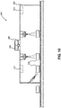
- a system 800 for applying a paint or coating to beverage containers (e.g. aluminum cans 802).
- the system 800 has a housing 804, inside which the coating and/or paint is applied to the cans 802.
- the housing 804 may include a vent 200 defining a passage 202 extending between the interior of the housing 804 and the exterior of the housing 804.
- the system 800 may further include one or more sensors 210 for quantifying one or more parameters within the system 800.
- the system 800 may include a flow meter 212 to quantify the amount of material applied to the cans 802. The operation of the vents 200, the sensors 210, and the flow meters 212 is described throughout this application and may be applied to system 800 as well.
Abstract
Description
- The present disclosure generally relates to dispensing and/or curing liquid coating materials and, more particularly, to systems and methods for monitoring and maintaining an acceptable solvent concentration when applying and/or curing liquid coating material.
- Many industrial applications require the use of discrete, well-defined and uniform coatings applied to predetermined areas. Conformal coating material is used to protect selected components of a circuit board from moisture, dirt, etc. Such coatings are very useful in varied processes, such as conformal coatings on non-uniform or irregular substrates like electronic circuit boards. It is desirable to obtain broad, uniform coatings using a non-contact applicator with sharp, square, cut-on and cut-off edges.
- The conformal coating material typically includes a solvent. During the application and curing of the conformal coating material, the solvent evaporates into the closed environment of the coating system and/or curing oven. Exceedingly high levels of solvent pose an increased fire risk and, as such, the evaporated solvent needs to be removed from the system to allow for uninterrupted operation of the system.
- Current systems require continuous extraction levels above a preset threshold to avoid reaching a dangerous solvent concentration. This level is often determined based on worst-case evaporation calculations. However, continuous extraction at the same level is energy inefficient. Therefore, there is a need for improved systems and methods for detecting the level of evaporated solvent in the system and for removing excess evaporated solvent in an efficient manner.
- Systems and methods for venting a solvent are disclosed. In one embodiment, the system includes an oven having an interior volume defining one or more heating zones, where the interior volume receives at least one substrate coated with a coating material comprising a solvent. The system further includes a vent coupled to the oven and defining a passage between the interior volume and the environment external to the oven, one or more solvent sensors measuring an amount of evaporated solvent present in the interior volume, and an optional fan removing at least a portion of the solvent from the interior volume.
- In another embodiment, the system includes a coating assembly having one or more applicators and a flow meter. The applicator is configured to apply a portion of a coating material comprising the solvent to a substrate. The flow meter is configured to determine an amount of coating material applied to the substrate. The system may also include an oven having an interior volume defining one or more heating zones. The interior volume receives the substrate coated with the coating material. The system also includes a vent coupled to the oven, where the vent defines a passage between the interior volume and the environment external to the oven. Finally, the system may include a fan in fluid communication with the passage and configured to remove at least a portion of the evaporated solvent from the interior volume.
- In yet another embodiment, the system includes a coating assembly defining a chamber, wherein the chamber contains one or more applicators configured to apply a portion of a coating material comprising the solvent to a substrate, and a flow meter configured to determine an amount of coating material applied to the substrate. The system also includes a vent, controller, and fan. The vent is coupled to the coating assembly, and defines a passage between the chamber and the environment external to the coating assembly. The controller is configured to determine an amount of evaporated solvent present in the chamber. Finally, the fan is in fluid communication with the passage and configured to remove at least a portion of the evaporated solvent from the chamber.
- In still another embodiment, the system includes a coating assembly including an applicator configured to apply a portion of a coating material comprising the solvent to a substrate. The system also includes an oven, a vent, a fan, and a controller. The oven has an interior volume defining one or more heating zones, where the interior volume receives the substrate coated with the coating material. The vent is coupled to the oven and defines a passage between the interior volume and the environment external to the oven. The fan is in fluid communication with the passage and configured to remove at least a portion of the evaporated solvent from the interior volume. Finally, the controller is configured to determine a concentration of evaporated solvent present in the interior volume and to operate the fan in response to the determined concentration of evaporated solvent present in the interior volume.
- In another embodiment, a system for venting a solvent is disclosed. The system includes a chamber having an interior volume including at least one substrate coated with a coating material comprising a solvent. The system also includes a vent coupled to the chamber, where the vent defines a passage between the interior volume and the environment external to the chamber. The system also includes a solvent sensor at least partially located in the interior volume and configured to measure an amount of evaporated solvent present in the interior volume. In addition, the system includes a fan in fluid communication with the passage and configured to remove at least a portion of the evaporated solvent from the interior volume.
- In another embodiment, a system for venting a solvent is disclosed. The system includes a coating assembly comprising an applicator and a flow meter. The applicator is configured to apply a coating material having the solvent to a substrate. The flow meter is configured to determine an amount of coating material applied to the substrate. The system also includes a chamber having an interior volume receiving the substrate coated with the coating material and a vent coupled to the chamber. The vent defines a passage between the interior volume and the environment external to the chamber. The system also includes a fan in fluid communication with the passage and configured to remove at least a portion of the evaporated solvent from the interior volume, and a controller configured to determine a concentration of evaporated solvent present in the interior volume based on the amount of coating material applied to the substrate, the evaporation rate of the solvent, the surface area coated on the substrate, the solvent content of the coating material, and the atmospheric volume of the interior volume.
- A method of venting a solvent is also disclosed. The method initially introduces a substrate at least partially coated with a coating material comprising a solvent into a heating zone of an oven. The substrate is then heated in the oven to cause the solvent to evaporate. Then, the concentration of the evaporated solvent in the heating zone is calculated.
- Another method of venting a solvent is also disclosed. The method initially receives a substrate at least partially coated with a coating material comprising a solvent into a chamber. Nest, the concentration of the evaporated solvent in the chamber is calculated, and, in response to the calculated concentration of the evaporated solvent in the chamber, at least a portion of the evaporated solvent is moved through a vent positioned on the chamber.
- The invention will now be further described by way of example with reference to the accompanying drawings, in which:
-
Fig. 1 illustrates a schematic view of a coating system in accordance with an embodiment; -
Fig. 2 illustrates a schematic view of a coating system in accordance with another embodiment; -
Fig. 3 illustrates a perspective view of an oven in accordance with another embodiment; -
Fig. 4 illustrates a coating system in accordance with another embodiment; -
Fig. 5 illustrates a coating assembly in accordance with an embodiment; -
Fig. 6 illustrates a flow diagram of an exemplary method in accordance with an embodiment; -
Fig. 7 illustrates a flow diagram with an exemplary method in accordance with another embodiment; -
Fig. 8 illustrates a flow diagram with an exemplary method in accordance with yet another embodiment; -
Fig. 9 illustrates a liquid paint application system in accordance with an embodiment; and -
Fig. 10 illustrates a beverage container coating system in accordance with an embodiment. - Aspects of the disclosure will now be described in detail with reference to the drawings, wherein like reference numbers refer to like elements throughout, unless specified otherwise.
- Systems and methods are disclosed for efficiently removing evaporated solvent from a coating system, such as a conformal coating system. A system for applying a conformal coating onto a substrate, such as a printed circuit board, may include an applicator that deposits the conformal coating onto the substrate, and an oven that can heat treat the coated substrate. After the conformal coating is applied to the substrate, the substrate may be moved to the oven for treatment. Alternatively, the applicator and the oven may be housed together. In some embodiments, the coating may contain volatile compounds, such as solvents, that are maintained at a safe concentration within the applicator, oven, or both.
- A
system 10 for curing a coating material may include anoven 100 and acoating assembly 120. Thecoating assembly 120 has acoating material source 124 and anapplicator 122. Referring toFigs.1-5 , the oven has aninterior volume 110 and one ormore heating zones 112. Eachheating zone 112 receives thecoated substrate 101 and heats the environment within theheating zone 112 to a predetermined temperature. The substrate may be moved on a conveyer belt. In one embodiment, eachheating zone 112 may be an enclosure that is separated from the rest of the oven by physical borders or dividers. In another embodiment, with specific reference to the illustrative embodiment inFig. 1 , eachheating zone 112 may be a region of theoven 100 that is not physically divided from the rest of the oven. In some embodiments, theheating zone 112 may be defined by theinterior volume 110 of the oven, such that theheating zone 112 is in fluid communication with theinterior volume 110. - The temperature in each
heating zone 112 may be fixed, or it may be adjusted during the heating process. The transition between one heating zone and an adjacent heating zone may be gradual and may include a temperature gradient ranging from the temperature of the first heating zone to the temperature of the second heating zone. In some embodiments, part of theinterior volume 110 that defines afirst heating zone 112 may also define asecond heating zone 112, such that theheating zones 112 overlap. - The
system 10 also includes avent 200. Thevent 200 is connected to theoven 100 to allow movement of gases, such as evaporated solvent, inside theoven 100 to an environment external to theoven 100. Thevent 200 includes an opening that defines apassage 202 between theinterior volume 110 of theoven 100 and the environment external to theoven 100 and, specifically between theheating zone 112 and the environment external to theoven 100. In some embodiments, a single vent may be accessible to the plurality ofheating zones 112, such that evaporated solvent in any of the plurality ofheating zones 112 may be moved to the environment external to theoven 100. Alternatively, theoven 100 may include a plurality ofvents 200, wherein each vent defines aseparate passage 202 between theinterior volume 110 and the environment external to theoven 100. - In some embodiments, the
vent 200 may have aregulator 206 that can be adjusted to vary the rate at which evaporated solvent can flow from theinterior volume 110 of theoven 100 to the environment external to theoven 100. Theregulator 206 may be positioned adjacent theinterior volume 110 of theoven 100, inside thepassage 202 defined by thevent 200, or on thevent 200 adjacent the exterior surface of theoven 100. In some embodiments, thevent 200 may includemultiple regulators 206 located in the same or in different locations within or adjacent to thevent 200. Aregulator 206 may include a baffle, a gate, a valve, or another suitable device that can be adjusted to permit or block the passage of the evaporated solvent. - In some embodiments, the
regulator 206 has an open configuration, a partially open configuration, and a closed configuration. In the open and partially open configurations, thepassage 202 is substantially unobstructed, and the evaporated solvent can move through the passage in the vent. In the closed configuration, thepassage 202 is substantially blocked such that the evaporated solvent is blocked within theinterior volume 110 of theoven 100. In the partially open configuration, thepassage 202 is obstructed more than in the open configuration but less than in the closed configuration, to allow for intermediate flow of the evaporated solvent. - Referring to
Fig. 3 , theregulator 206 may be avent gate 206a configured to rotate to partially or completely open theregulator 206. Thevent gate 206a may have one movable portion or it may have multiple movable portions, as shown inFig. 3 . In another embodiment shown inFig. 3 , theregulator 206 may be a hingedlid 206b positioned on top of thevent 200. The hingedlid 206b swings away from the vent into the open configuration, and returns to cover thevent 200 in the closed configuration. When closed, the hingedlid 206b substantially seals thevent 200 such that the evaporated solvent is blocked within theinterior volume 110 of theoven 100. - Referring to
Fig. 2 , for example, thesystem 10 can include afan 204 used to create a negative pressure in theinterior volume 110 of theoven 100. Thefan 204 may be positioned within theinterior volume 110 of theoven 100, within thevent 200 as shown inFig. 2 , or external to theoven 100 as shown inFIG. 4 . In some embodiments, the system may include multiple fans. In some embodiments, both afan 204 and aregulator 206 may be included. - In some embodiments, the
fan 204 may be disposed within or on avent 200 extending from thecoating assembly 120. In other embodiments, thefan 204 may be disposed in another portion of the system, such as a HVAC unit in fluid communication with thevent 200. For example, thesystem 10 may be kept inside a closed environment, such as anenclosure 300, and thefan 204 may be disposed on avent 200 that connects the inside of the closed environment with the outside environment. - The
fan 204 and/orregulator 206 may be actuated manually by a user, or they may be configured to automatically actuate in response to a program. For example, the evaporated solvent needs to be removed from thesystem 10 as the quantity of the evaporated solvent reaches a threshold level. As such, referring toFIG. 2 , the system may include asensor 210 that quantifies how much evaporated solvent is inside a closed volume, such as in the coating assembly 120 (sensor 210a) or in theinterior volume 110 of the oven 100 (sensor 210b). Thesystem 10 may havemultiple sensors 210 disposed in different volumes of the system. - In some embodiments, the
sensor 210 is a solvent sensor that is configured to detect the quantity of the evaporated solvent of a solvent. Thesensor 210 can provide real-time levels of evaporated solvent to acontroller 180, such as a computer or server, for the generation of alerts or signals to control extraction of the evaporated solvent. Thecontroller 180 may be located on theapplicator 122 or may be external to thesystem 10. Thecontroller 180 may be physically detached from thesystem 10 while maintaining a functional connection to the sensor 210 (for example, through wireless means). For example, when a predetermined threshold concentration of evaporated solvent is detected, the suction may be increased by adjusting the speed of thefan 204, adjusting theregulator 206 to a partial or completely open position, or by adjusting the HVAC system. Alternatively, if the concentration of evaporated solvent is greater than the predetermined threshold, the system may be shut down. - In some embodiments, the
system 10 may include aflow meter 212 within thecoating assembly 120. Referring toFig. 5 , theapplicator 122 may be in fluid communication with acoating source 124 and is configured to move coating material (not shown) from thecoating source 124 for application onto asubstrate 101. The amount of coating material moved through theapplicator 122 to thesubstrate 101 may be quantified with aflow meter 212. In some embodiments, theflow meter 212 may be disposed on theapplicator 122, for example on thetip 126 of theapplicator 122, such that it can measure how much coating material passes from the applicator to the substrate. In another embodiment, theflow meter 212 may be disposed at thecoating material source 124 or between the source and the applicator, such that theflow meter 212 can quantify the amount of coating material that passes from the source to the applicator. In some embodiments, theflow meter 212 may measure the displacement of the coating material within thecoating material source 124 or theapplicator 122. Some systems may have a plurality offlow meters 212 positioned at multiple locations within thecoating assembly 120. - The
flow meter 212 can measure one or more parameters of the flow of the coating material. In some embodiments,flow meter 212 may measure the volume, the velocity, or the pressure, and/or the duration of the flow. Theflow meter 212 may be connected to acontroller 180 configured to receive data from theflow meter 212 and perform analysis on the data. Thecontroller 180 may also be configured to analyze other parameters of the flow, such as the type of coating material, the characteristics of theapplicator 122 and/or theoven 100. - In some embodiments, instead of using a solvent sensor, it may be possible to estimate the concentration of evaporated solvent. For example, the
controller 180 may receive the quantity of coating material applied to one ormore substrates 101 flowing through the system 10 (e.g., from the flow meter 212), the concentration of the solvent material present in the coating material, the evaporation rate of the solvent, the surface area of the one ormore substrates 101 that is configured to receive the coating material, and the volume of interest, such as the volume of theinterior volume 110 of theoven 100. - The
controller 180 uses this information to estimate the concentration of evaporated solvent using the following formula:
- The
controller 180 then compares the calculated concentration of evaporated solvent to a predetermined threshold to control suction of the evaporated solvent. Thecontroller 180 may also generate an alert to a user if the calculated concentration of evaporated solvent is above the predetermine threshold or is above another alert threshold. In addition, the calculated concentration of evaporated solvent can be displayed to the user in real-time. To control suction of the evaporated solvent, thecontroller 180 can automatically adjust parameters for application of the coating material or adjust the speed of thefan 204, theregulator 206, or the HVAC system. - For example, if the
controller 180 determines that the estimated concentration of evaporated solvent is greater than the predetermined threshold, the controller may decrease the rate of application of the coating material or decrease the rate at which thesubstrates 101 enter thecoating assembly 120. If thecontroller 180 determines that the estimated concentration of evaporated solvent is lower than the predetermined threshold, thecontroller 180 may increase the rate of application of the coating material or increase the rate at which thesubstrates 101 enter thecoating assembly 120. - In some embodiments, the
system 10 may include anoven 100 or acoating assembly 120 as described herein. It will be understood that a system having an oven may interact with a system having a coating assembly, and this disclosure contemplates systems that have either anoven 100 or acoating assembly 120, as well as systems that have both anoven 100 and acoating assembly 120. - In operation, the
system 10 may include a dynamic feedback system. With reference toFig. 6 , amethod 400 for curing coating material on asubstrate 101 is described according to one embodiment. Initially, instep 402, thesubstrate 101 coated with a conformal coating is heat cured in theheating zone 112. While thesubstrate 101 is within theoven 100, thesolvent sensor 210 continuously measures the quantity of evaporated solvent inside the oven instep 404. Thesolvent sensor 210 may measure the solvent at predetermined time increments, once the oven reaches a preset temperature, or according to a program. - In
step 406, thecontroller 180 receives the quantity of evaporated solvent from thesolvent sensor 210 to determine the concentration of evaporated solvent based on the known volume of theheating zone 112 and/orinterior volume 110. If the concentration of evaporated solvent reaches a predetermined shutdown threshold, thesystem 10 may be configured to shutdown operation inblock 408a. If the concentration of evaporated solvent reaches an action threshold, which is lower than the shutdown threshold, thesystem 10 may actuate thefan 204 or HVAC system instep 408b or toggle theregulator 206 from the closed configuration to the open configuration or semi-open configuration instep 408c to control suction of the evaporated solvent. If the concentration of evaporated solvent is below the action threshold, thesystem 10 may maintain operating conditions without change. - In one embodiment, the shutdown threshold may be an evaporated solvent concentration of 25% of a Lower Flammable Limit. The action threshold is preferably below the shutdown threshold and may range, for example, between 5% and 20% of Lower Flammable Limit to enable the
system 10 to decrease the evaporated solvent concentration before shutting down. In some embodiments, themethod 400 may also include a warning threshold triggering an audible or visual alarm, or an electronic notification to one or more users. The warning threshold may be less than the action threshold, between the action threshold and the shutdown threshold, or above the shutdown threshold. - Referring to
Fig. 7 , amethod 500 is described using multiple thresholds to control the evaporated solvent concentration before shutdown. Instep 502, the concentration of evaporated solvent is determined as described above. If the solvent concentration equals or exceeds a first threshold instep 504, thesystem 10 may toggle theregulator 206 from a closed position to a semi-open or to an open position to open thepassage 202 ofvent 200. Theopen passage 202 permits the evaporated solvent to passively move out of the system, or allows air from the HVAC system to enter or exit the volume. If the concentration of solvent then reaches a second threshold that is higher than the first threshold instep 506, the system may actuate thefan 204 to actively move the evaporated solvent through thevent 200 by turning on thefan 204 or increasing the speed of thefan 204. If the evaporated solvent concentration continues to a third, shutdown threshold, the system may be configured to shut down. - The
system 10 may utilize aflow meter 212 or a timer that measures the time the coating material is applied to thesubstrate 101 to estimate the concentration of evaporated solvent. With reference toFig. 8 , amethod 600 for estimating the concentration of evaporated solvent using a flow meter or timer is described. Instep 602, coating material is applied to the substrate. Instep 604, theflow meter 212 measures the quantity of coating material applied to thesubstrate 101 or a timer measure the amount of time that theapplicator tip 126 is applying the coating material. As described above, theflow meter 212 may be disposed at different positions between thecoating material source 124 and thesubstrate 101. Without using theflow meter 212, the flow rate of the coating material may be known and multiplied by the time that theapplicator tip 126 is applying the coating material. - The
system 10 and/orcontroller 180 also stores additional parameters to estimate the concentration of evaporated solvent instep 606, as described above. Instep 608, the system determines whether the estimated concentration of evaporated solvent is greater than or equal to a predetermined threshold, such as the alert threshold, the action threshold, or the shutdown threshold. If the estimated concentration is higher, thesystem 10 may decrease the evaporated solvent concentration or shut down instep 608. - Various modifications or additions to the
system 10 are contemplated. For example, thesystem 10 may include a filter and/or a scrubber (not shown) such that the evaporated solvent that passes through thevent 200 is filtered or scrubbed before being released to the environment according local emission regulations. Thesubstrate 101 may alternatively be cured via gas convection or via application of radiation, such as infrared, ultraviolet, or visible radiation. -
System 10 may also include atransport element 211 that transfers the substrate from the coating system to the oven. The transport element may include a conveyor, an inverter or flipper, or another suitable structural feature that is configured to move the substrate through the system. Thetransfer element 211 may be disposed between the coating system and the oven, or it may be disposed within the coating system or the oven.Multiple transfer elements 211 may be present in the system, for example adjacent each of the coating system and the oven, such that themultiple transfer elements 211 may be positioned adjacent one another to move the substrate from the coating system to the oven and/or out of the oven. - In some embodiments, the transport element may include a
solvent sensor 210 that can be configured to sense and/or quantify the evaporated solvent and to send a signal to another element of the system. Referring toFig. 2 , thetransport system 211 may be disposed between thecoating assembly 120 and theoven 100 and may include asolvent sensor 210c. - The embodiments disclosed herein offer a number of advantages. Utilizing a solvent sensor to monitor the evaporated solvent concentration or a flow meter to estimate the evaporated solvent concentration enables for dynamic evaporated solvent removal. Such dynamic evaporated solvent removal decreases the fire and/or explosions risks associated with high levels of evaporated solvent, and minimizes the need for a system shutdown to improve system efficiency. In addition, by only removing evaporated solvent as necessary, energy costs associated removal of the evaporated solvent, including energy costs for cooling air fed into the
system 10, are reduced. - While the present disclosure depicts exemplary implementations related to application and curing of conformal coatings, it will be understood that the embodiments disclosed throughout this application may be utilized in a variety of other industrial applications. Similar advantages may be appreciated by incorporating one or more of the above embodiments in liquid painting systems for curing paint coatings or for applying coatings to cans or other containers.
- For example,
Fig. 9 shows an illustrative embodiment of asystem 700 for applying liquid paint todrums 702. Thesystem 700 has ahousing 704, inside which liquid paint is applied to thedrums 702. Thehousing 704 may include avent 200 defining apassage 202 extending between the interior of thehousing 704 and the exterior of thehousing 704. Thesystem 700 may further include one ormore sensors 210 for quantifying one or more parameters within thesystem 700. In some embodiments, thesystem 700 may include aflow meter 212 to quantify the amount of material applied to thedrums 702. The operation of thevents 200, thesensors 210, and theflow meters 212 is described throughout this application and may be applied tosystem 700 as well. - Referring to
Fig. 10 , asystem 800 is shown for applying a paint or coating to beverage containers (e.g. aluminum cans 802). Thesystem 800 has ahousing 804, inside which the coating and/or paint is applied to thecans 802. Thehousing 804 may include avent 200 defining apassage 202 extending between the interior of thehousing 804 and the exterior of thehousing 804. Thesystem 800 may further include one ormore sensors 210 for quantifying one or more parameters within thesystem 800. In some embodiments, thesystem 800 may include aflow meter 212 to quantify the amount of material applied to thecans 802. The operation of thevents 200, thesensors 210, and theflow meters 212 is described throughout this application and may be applied tosystem 800 as well. - While systems and methods have been described in connection with the various embodiments of the various figures, it will be appreciated by those skilled in the art that changes could be made to the embodiments. It is understood, therefore, that this disclosure is not limited to the particular embodiments disclosed.
- Embodiments of the invention can be described with reference to the following numbered clauses, with preferred features laid out in the dependent clauses:
- 1. A system for venting a solvent, the system comprising:
- an oven having an interior volume defining a heating zone, the interior volume receiving at least one substrate coated with a coating material comprising a solvent;
- a vent coupled to the oven, the vent defining a passage between the interior volume and the environment external to the oven;
- a solvent sensor at least partially located in the interior volume and configured to measure an amount of evaporated solvent present in the interior volume; and
- a fan in fluid communication with the passage and configured to remove at least a portion of the evaporated solvent from the interior volume.
- 2. The system of clause 1, wherein the fan is disposed within the vent such that when the fan is actuated, and the fan removes at least the portion of the evaporated solvent from the interior volume through the passage in the vent to the environment external to the oven.
- 3. The system of clause 2, wherein the fan is actuated in response to the measured amount of evaporated solvent present in the interior volume.
- 4. The system of clause 1, wherein the vent further comprises a regulator, the regulator being configured to toggle between an open configuration, a partially open configuration, and a closed configuration, wherein in the closed configuration, the regulator substantially blocks movement of the evaporated solvent from the interior volume through the passage and to the environment external the oven, and wherein in the open configuration and the partially open configuration, the regulator allows for movement of the evaporated solvent from the interior volume through the passage and to the environment external to the oven.
- 5. The system of clause 4, wherein the fan is disposed in the environment external to the oven and is configured to remove evaporated solvent from the interior volume through the regulator when the regulator is in the open configuration or partially open configuration.
- 6. The system of clause 4, wherein the regulator is toggled between the open configuration and the closed configuration in response to a command from the solvent sensor.
- 7. The system of clause 1, wherein the fan is disposed in the environment external to the oven and is configured to switch on and off, such that when the fan is on, the fan removes at least the portion of the evaporated solvent from the interior volume.
- 8. The system of any preceding clause, wherein the fan is actuated in response to the measured amount of evaporated solvent present in the interior volume.
- 9. The system of any preceding clause, wherein the speed of the fan is controlled based on the measured amount of evaporated solvent present in the interior volume.
- 10. The system of any preceding clause, wherein the heating zone includes a plurality of heating zones, the oven includes a plurality of vents, and each heating zone in the plurality of heating zones includes a corresponding one of the plurality of vents.
- 11. The system of any preceding clause, wherein the system is configured to shut down when the measured amount of evaporated solvent present in the interior volume is greater than or equal to a shutdown threshold.
- 12. The system of any preceding clause, wherein the system is configured to alert a user when the measured amount of evaporated solvent present in the interior volume is greater than or equal to a first threshold.
- 13. The system of any preceding clause, further comprising a flow meter configured to determine an amount of material applied to the substrate and a controller configured to determine an amount of evaporated solvent present in the oven,
wherein the controller is configured to determine a concentration of evaporated solvent present in the oven based on the amount of material applied to the substrate, the evaporation rate of the solvent, the surface area coated on the substrate, the solvent content of the applied material, and the volume of the oven. - 14. The system of any preceding clause, further comprising:
- a housing having an exterior and an interior configured to receive the substrate for coating;
- a vent defining a passage between the interior and the exterior of the housing; and
- a solvent sensor disposed in the housing and configured to measure an amount of evaporated solvent present in the housing.
- 15. The system of clause 14, further comprising a fan in fluid communication with the passage and configured to remove at least a portion of the evaporated solvent from the housing.
- 16. The system of clause 15, further comprising a flow meter configured to determine an amount of material applied to the substrate and a controller configured to determine an amount of evaporated solvent present in the housing,
wherein the controller is configured to determine a concentration of evaporated solvent present in the housing based on the amount of material applied to the substrate, the evaporation rate of the solvent, the surface area coated on the substrate, the solvent content of the applied material, and the volume of the housing. - 17. The system of any preceding clause, wherein the substrate is a steel drum.
- 18. The system of any one of clauses 1 to 16, wherein the substrate is an aluminum can.
- 19. A system for venting a solvent, the system comprising:
- a coating assembly comprising an applicator and a flow meter, the applicator being configured to apply a coating material to a substrate, a portion of the coating material comprising the solvent, and the flow meter configured to determine an amount of coating material applied to the substrate;
- an oven having an interior volume defining a heating zone, the interior volume receiving the substrate coated with the coating material;
- a vent coupled to the oven, the vent defining a passage between the interior volume and the environment external to the oven;
- a fan in fluid communication with the passage and configured to remove at least a portion of the evaporated solvent from the interior volume; and
- a controller configured to determine a concentration of evaporated solvent present in the interior volume based on the amount of coating material applied to the substrate, the evaporation rate of the solvent, the surface area coated on the substrate, the solvent content of the coating material, and the atmospheric volume of the interior volume.
- 20. The system of clause 19, wherein the controller is configured to determine the concentration of evaporated solvent present in the interior volume using the following formula:

- 21. The system of either clause 19 or
clause 20, wherein the controller is configured to operate the fan in response to the determined concentration of evaporated solvent present in the interior volume. - 22. The system of any one of clause 19 to 21, wherein the fan is disposed within the vent such that when the fan is actuated, and the fan removes at least the portion of the evaporated solvent from the interior volume through the passage in the vent to the environment external to the oven.
- 23. The system of any one of clause 19 to 22, wherein the vent further comprises a regulator, the regulator being configured to toggle between an open configuration, a partially open configuration, and a closed configuration, wherein in the closed configuration, the regulator substantially blocks movement of the evaporated solvent from the interior volume through the passage and to the environment external the oven, and wherein in the open configuration and the partially open configuration, the regulator allows for movement of the evaporated solvent from the interior volume through the passage and to the environment external to the oven.
- 24. The system of clause 23, wherein the fan is disposed in the environment external to the oven and is configured to remove evaporated solvent from the interior volume through the regulator when the regulator is in the open configuration or partially open configuration.
- 25. A system for venting a solvent, the system comprising:
- a coating assembly defining a chamber, the chamber containing an applicator configured to apply a coating material to a substrate, a portion of the coating material comprising the solvent, and a flow meter configured to determine an amount of coating material applied to the substrate;
- a vent coupled to the coating assembly, the vent defining a passage between the chamber and the environment external to the coating assembly;
- a controller configured to determine an amount of evaporated solvent present in the chamber; and
- a fan in fluid communication with the passage and configured to remove at least a portion of the evaporated solvent from the chamber.
- 26. The system of clause 25, wherein the controller is configured to determine a concentration of evaporated solvent present in the chamber based on the amount of coating material applied to the substrate, the evaporation rate of the solvent, the surface area coated on the substrate, the solvent content of the coating material, and the volume of the chamber.
- 27. The system of either clause 25 or clause 26, wherein the controller is configured to operate the fan in response to the determined concentration of evaporated solvent present in the chamber.
- 28. The system of any one of clauses 25 to 27, wherein the fan is disposed within the vent such that when the fan is actuated, and the fan removes at least the portion of the evaporated solvent from the interior volume through the passage in the vent to the environment external to the coating assembly.
- 29. The system of any one of clauses 25 to 27, wherein the vent further comprises a regulator, the regulator being configured to toggle between an open configuration, a partially open configuration, and a closed configuration, wherein in the closed configuration, the regulator substantially blocks movement of the evaporated solvent from the interior volume through the passage and to the environment external the coating assembly, and wherein in the open configuration and the partially open configuration, the regulator allows for movement of the evaporated solvent from the interior volume through the passage and to the environment external to the coating assembly.
- 30. The system of clause 29, wherein the fan is disposed in the environment external to the coating assembly and is configured to remove evaporated solvent from the interior volume through the regulator when the regulator is in the open configuration or partially open configuration.
- 31. A system for venting a solvent, the system comprising:
- a coating assembly comprising an applicator, the applicator being configured to apply a coating material to a substrate, a portion of the coating material comprising the solvent;
- an oven having an interior volume defining a heating zone, the interior volume receiving the substrate coated with the coating material;
- a vent coupled to the oven, the vent defining a passage between the interior volume and the environment external to the oven;
- a fan in fluid communication with the passage and configured to remove at least a portion of the evaporated solvent from the interior volume; and
- a controller configured to determine a concentration of evaporated solvent present in the interior volume and to operate the fan in response to the determined concentration of evaporated solvent present in the interior volume.
- 32. The system of clause 31, wherein the concentration of evaporated is configured to determine the concentration of evaporated solvent present in the interior volume based on an amount of coating material applied to the substrate, the evaporation rate of the solvent, the surface area coated on the substrate, the solvent content of the coating material, and the atmospheric volume of the interior volume to calculate the concentration of evaporated solvent in the interior volume.
- 33. The system of clause 32, wherein the controller is configured to determine the concentration of evaporated solvent present in the interior volume using the following formula:

- 34. The system of either clause 32 or clause 33, wherein the amount of coating material applied to the substrate is determined based on the time that a valve of the applicator is open to apply the coating material to the substrate and the flow rate of the applicator.
- 35. The system of any one of clauses 31 to 34, wherein the fan is disposed within the vent such that when the fan is actuated, and the fan removes at least the portion of the evaporated solvent from the interior volume through the passage in the vent to the environment external to the oven.
- 36. The system of any one of clauses 31 to 34, wherein the vent further comprises a regulator, the regulator being configured to toggle between an open configuration, a partially open configuration, and a closed configuration, wherein in the closed configuration, the regulator substantially blocks movement of the evaporated solvent from the interior volume through the passage and to the environment external the oven, and wherein in the open configuration and the partially open configuration, the regulator allows for movement of the evaporated solvent from the interior volume through the passage and to the environment external to the oven.
- 37. The system of clause 36, wherein the fan is disposed in the environment external to the oven and is configured to remove evaporated solvent from the interior volume through the regulator when the regulator is in the open configuration or partially open configuration.
- 38. A method of venting a solvent, the method comprising:
- receiving a substrate at least partially coated with a coating material comprising a solvent into a heating zone of an oven;
- heating the substrate in the oven to cause the solvent to evaporate;
- calculating the concentration of the evaporated solvent in the heating zone; and
- moving, in response to the calculated concentration of the evaporated solvent in the oven, at least a portion of the evaporated solvent through a vent positioned on the oven.
- 39. The method of clause 38, further comprising heating the substrate in the oven to cause the solvent to evaporate.
- 40. The method of either clause 38 or clause 39, wherein calculating the concentration of the evaporated solvent in the heating zone comprises using a solvent sensor configured to measure an amount of evaporated solvent present in the oven.
- 41. The method of any one of clauses 38 to 40, wherein calculating the concentration of evaporated solvent in the heating zone comprises using the volume of the coating material applied to the substrate, the solvent content in the coating material, the evaporation rate of the solvent, the surface area coated on the substrate, and the atmospheric volume of the oven to calculate the concentration of evaporated solvent in the oven.
- 42. The method of clause 41, further comprising shutting down the oven if the calculated concentration of evaporated solvent exceeds a shutdown threshold value.
- 43. The method of any one of clauses 38 to 42, wherein the vent includes a regulator configured to toggle between an open configuration or partially open configuration that permits movement of the evaporated solvent through the regulator, and a closed configuration that blocks movement of the evaporated solvent through the regulator, and moving at least the portion of the evaporated solvent through the vent comprises toggling the regulator to the open or partially open configuration.
- 44. The method of any one of clauses 38 to 43, wherein a fan is disposed in the environment external to the oven, and moving at least the portion of the evaporated solvent through the vent positioned on the oven comprises actuating the fan to cause at least the portion of the evaporated solvent to move through the vent.
- 45. The method of any one of clauses 38 to 42, wherein the vent includes a fan, and moving at least the portion of the evaporated solvent through the vent positioned on the oven comprises actuating the fan to cause at least the portion of the evaporated solvent to move through the vent.
Claims (15)
- A system for venting a solvent, the system comprising:an oven having an interior volume defining a heating zone, the interior volume receiving at least one substrate coated with a coating material comprising a solvent;a vent coupled to the oven, the vent defining a passage between the interior volume and the environment external to the oven;a solvent sensor at least partially located in the interior volume and configured to measure an amount of evaporated solvent present in the interior volume; anda fan in fluid communication with the passage and configured to remove at least a portion of the evaporated solvent from the interior volume.
- The system of claim 1, wherein the fan is disposed within the vent such that when the fan is actuated, and the fan removes at least the portion of the evaporated solvent from the interior volume through the passage in the vent to the environment external to the oven.
- The system of claim 1, wherein the fan is disposed in the environment external to the oven and is configured to switch on and off, such that when the fan is on, the fan removes at least the portion of the evaporated solvent from the interior volume.
- The system of any preceding claim, wherein the vent further comprises a regulator, the regulator being configured to toggle between an open configuration, a partially open configuration, and a closed configuration, wherein in the closed configuration, the regulator substantially blocks movement of the evaporated solvent from the interior volume through the passage and to the environment external the oven, and wherein in the open configuration and the partially open configuration, the regulator allows for movement of the evaporated solvent from the interior volume through the passage and to the environment external to the oven.
- The system of any preceding claim, wherein the speed of the fan is controlled based on the measured amount of evaporated solvent present in the interior volume.
- The system of any preceding claim, wherein the heating zone includes a plurality of heating zones, the oven includes a plurality of vents, and each heating zone in the plurality of heating zones includes a corresponding one of the plurality of vents.
- The system of any preceding claim, wherein the system is configured to shut down when the measured amount of evaporated solvent present in the interior volume is greater than or equal to a shutdown threshold.
- The system of any preceding claim, further comprising a flow meter configured to determine an amount of material applied to the substrate and a controller configured to determine an amount of evaporated solvent present in the oven,
wherein the controller is configured to determine a concentration of evaporated solvent present in the oven based on the amount of material applied to the substrate, the evaporation rate of the solvent, the surface area coated on the substrate, the solvent content of the applied material, and the volume of the oven. - The system of any preceding claim, further comprising:a housing having an exterior and an interior configured to receive the substrate for coating;a vent defining a passage between the interior and the exterior of the housing; anda solvent sensor disposed in the housing and configured to measure an amount of evaporated solvent present in the housing.
- The system of claim 9, further comprising a flow meter configured to determine an amount of material applied to the substrate and a controller configured to determine an amount of evaporated solvent present in the housing,
wherein the controller is configured to determine a concentration of evaporated solvent present in the housing based on the amount of material applied to the substrate, the evaporation rate of the solvent, the surface area coated on the substrate, the solvent content of the applied material, and the volume of the housing. - A method of venting a solvent, the method comprising:receiving a substrate at least partially coated with a coating material comprising a solvent into a heating zone of an oven;heating the substrate in the oven to cause the solvent to evaporate;calculating the concentration of the evaporated solvent in the heating zone; andmoving, in response to the calculated concentration of the evaporated solvent in the oven, at least a portion of the evaporated solvent through a vent positioned on the oven.
- The method of claim 11, wherein calculating the concentration of the evaporated solvent in the heating zone comprises using a solvent sensor configured to measure an amount of evaporated solvent present in the oven.
- The method of either claim 11 or claim 12, wherein calculating the concentration of evaporated solvent in the heating zone comprises using the volume of the coating material applied to the substrate, the solvent content in the coating material, the evaporation rate of the solvent, the surface area coated on the substrate, and the atmospheric volume of the oven to calculate the concentration of evaporated solvent in the oven.
- The method of any one of claims 11 to 13, wherein the vent includes a fan, and moving at least the portion of the evaporated solvent through the vent positioned on the oven comprises actuating the fan to cause at least the portion of the evaporated solvent to move through the vent.
- The method of any one of claims 11 to 14, wherein the vent includes a regulator configured to toggle between an open configuration or partially open configuration that permits movement of the evaporated solvent through the regulator, and a closed configuration that blocks movement of the evaporated solvent through the regulator, and moving at least the portion of the evaporated solvent through the vent comprises toggling the regulator to the open or partially open configuration.
Priority Applications (1)
| Application Number | Priority Date | Filing Date | Title |
|---|---|---|---|
| EP21157651.7A EP3842721A1 (en) | 2017-07-06 | 2018-07-05 | Systems and methods for solvent extraction |
Applications Claiming Priority (2)
| Application Number | Priority Date | Filing Date | Title |
|---|---|---|---|
| US201762529144P | 2017-07-06 | 2017-07-06 | |
| US16/017,386 US10821466B2 (en) | 2017-07-06 | 2018-06-25 | Systems and methods for solvent extraction |
Related Child Applications (2)
| Application Number | Title | Priority Date | Filing Date |
|---|---|---|---|
| EP21157651.7A Division EP3842721A1 (en) | 2017-07-06 | 2018-07-05 | Systems and methods for solvent extraction |
| EP21157651.7A Division-Into EP3842721A1 (en) | 2017-07-06 | 2018-07-05 | Systems and methods for solvent extraction |
Publications (3)
| Publication Number | Publication Date |
|---|---|
| EP3425315A1 true EP3425315A1 (en) | 2019-01-09 |
| EP3425315A8 EP3425315A8 (en) | 2020-07-15 |
| EP3425315B1 EP3425315B1 (en) | 2021-04-21 |
Family
ID=63014305
Family Applications (2)
| Application Number | Title | Priority Date | Filing Date |
|---|---|---|---|
| EP21157651.7A Pending EP3842721A1 (en) | 2017-07-06 | 2018-07-05 | Systems and methods for solvent extraction |
| EP18182020.0A Active EP3425315B1 (en) | 2017-07-06 | 2018-07-05 | Systems and methods for solvent extraction |
Family Applications Before (1)
| Application Number | Title | Priority Date | Filing Date |
|---|---|---|---|
| EP21157651.7A Pending EP3842721A1 (en) | 2017-07-06 | 2018-07-05 | Systems and methods for solvent extraction |
Country Status (6)
| Country | Link |
|---|---|
| US (2) | US10821466B2 (en) |
| EP (2) | EP3842721A1 (en) |
| JP (1) | JP2019022883A (en) |
| KR (1) | KR102653081B1 (en) |
| CN (1) | CN109201431B (en) |
| TW (1) | TWI806880B (en) |
Families Citing this family (3)
| Publication number | Priority date | Publication date | Assignee | Title |
|---|---|---|---|---|
| US10821466B2 (en) | 2017-07-06 | 2020-11-03 | Nordson Corporation | Systems and methods for solvent extraction |
| US20220008951A1 (en) * | 2018-11-21 | 2022-01-13 | Nordson Corporation | Adhesive dispenser with slotted nozzle assembly |
| CN114216310B (en) * | 2022-02-22 | 2022-04-29 | 四川英创力电子科技股份有限公司 | Manufacturing device and manufacturing method of fine circuit PCB |
Citations (7)
| Publication number | Priority date | Publication date | Assignee | Title |
|---|---|---|---|---|
| US4872270A (en) * | 1988-03-09 | 1989-10-10 | Eastman Kodak Company | Drying process |
| US5567237A (en) * | 1993-06-22 | 1996-10-22 | Ciba-Geigy Corporation | Continuous drier for board-shaped piece material and coating installation comprising such a continuous drier |
| US5855077A (en) * | 1995-12-04 | 1999-01-05 | Samsung Electronics Co., Ltd. | Apparatus for drying semiconductor wafers using isopropyl alcohol |
| US5956859A (en) * | 1997-05-22 | 1999-09-28 | Ryoden Semiconductor System Emgineering Corporation | Drying apparatus for processing surface of substrate |
| US20010005525A1 (en) * | 1993-09-24 | 2001-06-28 | Scheufler Fred G. | Method of drying substrates and use thereof |
| US20060137213A1 (en) * | 2004-12-24 | 2006-06-29 | Seiko Epson Corporation | Solvent removal apparatus and method |
| EP3208565A1 (en) * | 2016-02-18 | 2017-08-23 | New Instruments and Research for Analysis Srl | Automatic exhaust air recirculation system for a printing machine of the flexographic or rotary type, or for a laminating machine |
Family Cites Families (24)
| Publication number | Priority date | Publication date | Assignee | Title |
|---|---|---|---|---|
| US2203422A (en) * | 1937-07-24 | 1940-06-04 | Us Hoffman Machinery Corp | Apparatus for drying |
| US2470043A (en) * | 1942-04-15 | 1949-05-10 | Pantex Mfg Corp | Apparatus for drying having safety and sequence controls |
| US4216592A (en) * | 1978-09-15 | 1980-08-12 | George Koch Sons, Inc. | Drying oven |
| US4266504A (en) * | 1979-08-10 | 1981-05-12 | Deere & Company | Paint spraying assembly |
| JPS5941772A (en) * | 1982-08-31 | 1984-03-08 | 井上金属工業株式会社 | Method of continuously drying organic solvent applied material |
| JPH0661520B2 (en) * | 1989-01-27 | 1994-08-17 | 昭和アルミニウム缶株式会社 | Drying and baking equipment for paint |
| JPH03270757A (en) * | 1990-03-19 | 1991-12-02 | Nittetsu Drum Kk | Drum can's chime painting method and its apparatus |
| JP3081439B2 (en) * | 1994-03-24 | 2000-08-28 | トリニティ工業株式会社 | Dry painting booth |
| JP2638490B2 (en) * | 1994-07-29 | 1997-08-06 | 中外炉工業株式会社 | Operating method of drying and baking oven |
| US6953047B2 (en) * | 2002-01-14 | 2005-10-11 | Air Products And Chemicals, Inc. | Cabinet for chemical delivery with solvent purging |
| JP2004344728A (en) * | 2003-05-21 | 2004-12-09 | Hitachi Industries Co Ltd | Paste coating transfer device |
| JP2005209970A (en) * | 2004-01-26 | 2005-08-04 | Matsushita Electric Ind Co Ltd | Heater of element to be coated with resist and method of monitoring the same |
| KR100689797B1 (en) * | 2005-01-22 | 2007-03-08 | 권혁선 | A drying system use for water soluble paints of automatic painting line |
| KR200394547Y1 (en) * | 2005-06-24 | 2005-09-02 | 아텍 엔지니어링 주식회사 | Apparatus for drying |
| JP2007155297A (en) * | 2005-12-08 | 2007-06-21 | Hirayama Setsubi Kk | Drying method of coating sheet |
| EP2103339B8 (en) * | 2006-12-27 | 2021-01-20 | Mitsubishi Power, Ltd. | Exhaust gas treating method and apparatus |
| JP5163532B2 (en) * | 2009-02-20 | 2013-03-13 | コニカミノルタホールディングス株式会社 | Coating liquid coating method and coating system |
| CN102564949B (en) * | 2010-12-30 | 2014-03-12 | 神基科技股份有限公司 | Gas detecting system and gas detecting method |
| US20120238075A1 (en) * | 2011-03-09 | 2012-09-20 | Tokyo Ohka Kogyo Co., Ltd. | Coating apparatus and coating method |
| CN105308347B (en) | 2013-06-19 | 2017-02-22 | 新日铁住金株式会社 | Caliper brake device for railway vehicle |
| KR101621269B1 (en) * | 2014-01-06 | 2016-05-16 | (주)삼일기계 | Integrated control device of coating and laminating machine |
| JP6425574B2 (en) * | 2015-02-09 | 2018-11-21 | トリニティ工業株式会社 | Painting equipment |
| JP6280194B1 (en) * | 2016-12-12 | 2018-02-14 | 中外炉工業株式会社 | Paint drying apparatus and paint drying method |
| US10821466B2 (en) | 2017-07-06 | 2020-11-03 | Nordson Corporation | Systems and methods for solvent extraction |
-
2018
- 2018-06-25 US US16/017,386 patent/US10821466B2/en active Active
- 2018-07-05 KR KR1020180078410A patent/KR102653081B1/en active IP Right Grant
- 2018-07-05 EP EP21157651.7A patent/EP3842721A1/en active Pending
- 2018-07-05 EP EP18182020.0A patent/EP3425315B1/en active Active
- 2018-07-06 CN CN201810738263.0A patent/CN109201431B/en active Active
- 2018-07-06 TW TW107123401A patent/TWI806880B/en active
- 2018-07-06 JP JP2018128708A patent/JP2019022883A/en not_active Ceased
-
2020
- 2020-09-25 US US17/031,968 patent/US11577270B2/en active Active
Patent Citations (7)
| Publication number | Priority date | Publication date | Assignee | Title |
|---|---|---|---|---|
| US4872270A (en) * | 1988-03-09 | 1989-10-10 | Eastman Kodak Company | Drying process |
| US5567237A (en) * | 1993-06-22 | 1996-10-22 | Ciba-Geigy Corporation | Continuous drier for board-shaped piece material and coating installation comprising such a continuous drier |
| US20010005525A1 (en) * | 1993-09-24 | 2001-06-28 | Scheufler Fred G. | Method of drying substrates and use thereof |
| US5855077A (en) * | 1995-12-04 | 1999-01-05 | Samsung Electronics Co., Ltd. | Apparatus for drying semiconductor wafers using isopropyl alcohol |
| US5956859A (en) * | 1997-05-22 | 1999-09-28 | Ryoden Semiconductor System Emgineering Corporation | Drying apparatus for processing surface of substrate |
| US20060137213A1 (en) * | 2004-12-24 | 2006-06-29 | Seiko Epson Corporation | Solvent removal apparatus and method |
| EP3208565A1 (en) * | 2016-02-18 | 2017-08-23 | New Instruments and Research for Analysis Srl | Automatic exhaust air recirculation system for a printing machine of the flexographic or rotary type, or for a laminating machine |
Also Published As
| Publication number | Publication date |
|---|---|
| US11577270B2 (en) | 2023-02-14 |
| US10821466B2 (en) | 2020-11-03 |
| CN109201431B (en) | 2023-08-15 |
| EP3842721A1 (en) | 2021-06-30 |
| CN109201431A (en) | 2019-01-15 |
| KR102653081B1 (en) | 2024-04-01 |
| TWI806880B (en) | 2023-07-01 |
| US20190009298A1 (en) | 2019-01-10 |
| TW201906655A (en) | 2019-02-16 |
| US20210008587A1 (en) | 2021-01-14 |
| KR20190005779A (en) | 2019-01-16 |
| JP2019022883A (en) | 2019-02-14 |
| EP3425315B1 (en) | 2021-04-21 |
| EP3425315A8 (en) | 2020-07-15 |
Similar Documents
| Publication | Publication Date | Title |
|---|---|---|
| US11577270B2 (en) | Systems and methods for solvent extraction | |
| US20210153509A1 (en) | Forced moisture evacuation for rapid baking | |
| US8726535B2 (en) | Method, apparatus and system for controlling heated air drying | |
| US20070256479A1 (en) | Gravimetric moisture measurement instrument | |
| US5558010A (en) | Food storage chamber door open compensation | |
| JP2010511460A5 (en) | ||
| JP5884238B2 (en) | Humidity detection device and environmental test device equipped with the same | |
| CN110383032A (en) | Portable moisture analyzer for natural gas | |
| CA3062280A1 (en) | Automated drying and curing chamber | |
| US5595109A (en) | Food storage device with dehumidification means | |
| JP2015203612A (en) | Environment test device and temperature-humidity control method | |
| EP0000955B1 (en) | Method for browning foods in a microwave oven | |
| CN110954664B (en) | Environment monitoring and treating system and method | |
| JP2019022883A5 (en) | ||
| US6916445B2 (en) | System and method for decontaminating articles | |
| AU2013330388B2 (en) | Biological safety cabinet with a falling-film evaporator | |
| CN110933937A (en) | Combined device and method for smoothing the surface of plastic products | |
| WO2002090855A1 (en) | Absolute humidity sensor to control drying equipment | |
| US20220057138A1 (en) | Rf treatment systems and methods | |
| JP6325882B2 (en) | Decontamination method and apparatus | |
| US6094924A (en) | Method for controlling the gas extraction rate from a cryogenic apparatus and apparatus therefor | |
| GB2532741A (en) | Method and apparatus for monitoring fog density | |
| Stokes et al. | A free-standing cabinet for cyanoacrylate fuming | |
| KR20100003931A (en) | Apparatus for treating food garbage and method for controlling dryness of food garbage | |
| CN114544417A (en) | Volatilization rate measuring device and method |
Legal Events
| Date | Code | Title | Description |
|---|---|---|---|
| PUAI | Public reference made under article 153(3) epc to a published international application that has entered the european phase |
Free format text: ORIGINAL CODE: 0009012 |
|
| STAA | Information on the status of an ep patent application or granted ep patent |
Free format text: STATUS: THE APPLICATION HAS BEEN PUBLISHED |
|
| AK | Designated contracting states |
Kind code of ref document: A1 Designated state(s): AL AT BE BG CH CY CZ DE DK EE ES FI FR GB GR HR HU IE IS IT LI LT LU LV MC MK MT NL NO PL PT RO RS SE SI SK SM TR |
|
| AX | Request for extension of the european patent |
Extension state: BA ME |
|
| STAA | Information on the status of an ep patent application or granted ep patent |
Free format text: STATUS: REQUEST FOR EXAMINATION WAS MADE |
|
| 17P | Request for examination filed |
Effective date: 20190702 |
|
| RBV | Designated contracting states (corrected) |
Designated state(s): AL AT BE BG CH CY CZ DE DK EE ES FI FR GB GR HR HU IE IS IT LI LT LU LV MC MK MT NL NO PL PT RO RS SE SI SK SM TR |
|
| STAA | Information on the status of an ep patent application or granted ep patent |
Free format text: STATUS: EXAMINATION IS IN PROGRESS |
|
| 17Q | First examination report despatched |
Effective date: 20191113 |
|
| GRAP | Despatch of communication of intention to grant a patent |
Free format text: ORIGINAL CODE: EPIDOSNIGR1 |
|
| STAA | Information on the status of an ep patent application or granted ep patent |
Free format text: STATUS: GRANT OF PATENT IS INTENDED |
|
| RIN1 | Information on inventor provided before grant (corrected) |
Inventor name: ORLA-JENSEN, PER Inventor name: ETIENNE, STEPHANE |
|
| INTG | Intention to grant announced |
Effective date: 20200622 |
|
| GRAJ | Information related to disapproval of communication of intention to grant by the applicant or resumption of examination proceedings by the epo deleted |
Free format text: ORIGINAL CODE: EPIDOSDIGR1 |
|
| STAA | Information on the status of an ep patent application or granted ep patent |
Free format text: STATUS: EXAMINATION IS IN PROGRESS |
|
| GRAP | Despatch of communication of intention to grant a patent |
Free format text: ORIGINAL CODE: EPIDOSNIGR1 |
|
| STAA | Information on the status of an ep patent application or granted ep patent |
Free format text: STATUS: GRANT OF PATENT IS INTENDED |
|
| INTC | Intention to grant announced (deleted) | ||
| INTG | Intention to grant announced |
Effective date: 20201111 |
|
| GRAS | Grant fee paid |
Free format text: ORIGINAL CODE: EPIDOSNIGR3 |
|
| GRAA | (expected) grant |
Free format text: ORIGINAL CODE: 0009210 |
|
| STAA | Information on the status of an ep patent application or granted ep patent |
Free format text: STATUS: THE PATENT HAS BEEN GRANTED |
|
| AK | Designated contracting states |
Kind code of ref document: B1 Designated state(s): AL AT BE BG CH CY CZ DE DK EE ES FI FR GB GR HR HU IE IS IT LI LT LU LV MC MK MT NL NO PL PT RO RS SE SI SK SM TR |
|
| REG | Reference to a national code |
Ref country code: GB Ref legal event code: FG4D |
|
| REG | Reference to a national code |
Ref country code: CH Ref legal event code: EP |
|
| REG | Reference to a national code |
Ref country code: DE Ref legal event code: R096 Ref document number: 602018015739 Country of ref document: DE Ref country code: IE Ref legal event code: FG4D |
|
| REG | Reference to a national code |
Ref country code: AT Ref legal event code: REF Ref document number: 1385065 Country of ref document: AT Kind code of ref document: T Effective date: 20210515 |
|
| REG | Reference to a national code |
Ref country code: NL Ref legal event code: FP |
|
| REG | Reference to a national code |
Ref country code: LT Ref legal event code: MG9D |
|
| REG | Reference to a national code |
Ref country code: AT Ref legal event code: MK05 Ref document number: 1385065 Country of ref document: AT Kind code of ref document: T Effective date: 20210421 |
|
| PG25 | Lapsed in a contracting state [announced via postgrant information from national office to epo] |
Ref country code: FI Free format text: LAPSE BECAUSE OF FAILURE TO SUBMIT A TRANSLATION OF THE DESCRIPTION OR TO PAY THE FEE WITHIN THE PRESCRIBED TIME-LIMIT Effective date: 20210421 Ref country code: HR Free format text: LAPSE BECAUSE OF FAILURE TO SUBMIT A TRANSLATION OF THE DESCRIPTION OR TO PAY THE FEE WITHIN THE PRESCRIBED TIME-LIMIT Effective date: 20210421 Ref country code: LT Free format text: LAPSE BECAUSE OF FAILURE TO SUBMIT A TRANSLATION OF THE DESCRIPTION OR TO PAY THE FEE WITHIN THE PRESCRIBED TIME-LIMIT Effective date: 20210421 Ref country code: BG Free format text: LAPSE BECAUSE OF FAILURE TO SUBMIT A TRANSLATION OF THE DESCRIPTION OR TO PAY THE FEE WITHIN THE PRESCRIBED TIME-LIMIT Effective date: 20210721 Ref country code: AT Free format text: LAPSE BECAUSE OF FAILURE TO SUBMIT A TRANSLATION OF THE DESCRIPTION OR TO PAY THE FEE WITHIN THE PRESCRIBED TIME-LIMIT Effective date: 20210421 |
|
| PG25 | Lapsed in a contracting state [announced via postgrant information from national office to epo] |
Ref country code: SE Free format text: LAPSE BECAUSE OF FAILURE TO SUBMIT A TRANSLATION OF THE DESCRIPTION OR TO PAY THE FEE WITHIN THE PRESCRIBED TIME-LIMIT Effective date: 20210421 Ref country code: RS Free format text: LAPSE BECAUSE OF FAILURE TO SUBMIT A TRANSLATION OF THE DESCRIPTION OR TO PAY THE FEE WITHIN THE PRESCRIBED TIME-LIMIT Effective date: 20210421 Ref country code: PT Free format text: LAPSE BECAUSE OF FAILURE TO SUBMIT A TRANSLATION OF THE DESCRIPTION OR TO PAY THE FEE WITHIN THE PRESCRIBED TIME-LIMIT Effective date: 20210823 Ref country code: PL Free format text: LAPSE BECAUSE OF FAILURE TO SUBMIT A TRANSLATION OF THE DESCRIPTION OR TO PAY THE FEE WITHIN THE PRESCRIBED TIME-LIMIT Effective date: 20210421 Ref country code: NO Free format text: LAPSE BECAUSE OF FAILURE TO SUBMIT A TRANSLATION OF THE DESCRIPTION OR TO PAY THE FEE WITHIN THE PRESCRIBED TIME-LIMIT Effective date: 20210721 Ref country code: LV Free format text: LAPSE BECAUSE OF FAILURE TO SUBMIT A TRANSLATION OF THE DESCRIPTION OR TO PAY THE FEE WITHIN THE PRESCRIBED TIME-LIMIT Effective date: 20210421 Ref country code: IS Free format text: LAPSE BECAUSE OF FAILURE TO SUBMIT A TRANSLATION OF THE DESCRIPTION OR TO PAY THE FEE WITHIN THE PRESCRIBED TIME-LIMIT Effective date: 20210821 Ref country code: GR Free format text: LAPSE BECAUSE OF FAILURE TO SUBMIT A TRANSLATION OF THE DESCRIPTION OR TO PAY THE FEE WITHIN THE PRESCRIBED TIME-LIMIT Effective date: 20210722 |
|
| REG | Reference to a national code |
Ref country code: DE Ref legal event code: R097 Ref document number: 602018015739 Country of ref document: DE |
|
| PG25 | Lapsed in a contracting state [announced via postgrant information from national office to epo] |
Ref country code: RO Free format text: LAPSE BECAUSE OF FAILURE TO SUBMIT A TRANSLATION OF THE DESCRIPTION OR TO PAY THE FEE WITHIN THE PRESCRIBED TIME-LIMIT Effective date: 20210421 Ref country code: DK Free format text: LAPSE BECAUSE OF FAILURE TO SUBMIT A TRANSLATION OF THE DESCRIPTION OR TO PAY THE FEE WITHIN THE PRESCRIBED TIME-LIMIT Effective date: 20210421 Ref country code: CZ Free format text: LAPSE BECAUSE OF FAILURE TO SUBMIT A TRANSLATION OF THE DESCRIPTION OR TO PAY THE FEE WITHIN THE PRESCRIBED TIME-LIMIT Effective date: 20210421 Ref country code: SM Free format text: LAPSE BECAUSE OF FAILURE TO SUBMIT A TRANSLATION OF THE DESCRIPTION OR TO PAY THE FEE WITHIN THE PRESCRIBED TIME-LIMIT Effective date: 20210421 Ref country code: SK Free format text: LAPSE BECAUSE OF FAILURE TO SUBMIT A TRANSLATION OF THE DESCRIPTION OR TO PAY THE FEE WITHIN THE PRESCRIBED TIME-LIMIT Effective date: 20210421 Ref country code: EE Free format text: LAPSE BECAUSE OF FAILURE TO SUBMIT A TRANSLATION OF THE DESCRIPTION OR TO PAY THE FEE WITHIN THE PRESCRIBED TIME-LIMIT Effective date: 20210421 Ref country code: ES Free format text: LAPSE BECAUSE OF FAILURE TO SUBMIT A TRANSLATION OF THE DESCRIPTION OR TO PAY THE FEE WITHIN THE PRESCRIBED TIME-LIMIT Effective date: 20210421 |
|
| PLBE | No opposition filed within time limit |
Free format text: ORIGINAL CODE: 0009261 |
|
| STAA | Information on the status of an ep patent application or granted ep patent |
Free format text: STATUS: NO OPPOSITION FILED WITHIN TIME LIMIT |
|
| REG | Reference to a national code |
Ref country code: CH Ref legal event code: PL |
|
| 26N | No opposition filed |
Effective date: 20220124 |
|
| PG25 | Lapsed in a contracting state [announced via postgrant information from national office to epo] |
Ref country code: MC Free format text: LAPSE BECAUSE OF FAILURE TO SUBMIT A TRANSLATION OF THE DESCRIPTION OR TO PAY THE FEE WITHIN THE PRESCRIBED TIME-LIMIT Effective date: 20210421 |
|
| REG | Reference to a national code |
Ref country code: BE Ref legal event code: MM Effective date: 20210731 |
|
| PG25 | Lapsed in a contracting state [announced via postgrant information from national office to epo] |
Ref country code: LI Free format text: LAPSE BECAUSE OF NON-PAYMENT OF DUE FEES Effective date: 20210731 Ref country code: CH Free format text: LAPSE BECAUSE OF NON-PAYMENT OF DUE FEES Effective date: 20210731 |
|
| PG25 | Lapsed in a contracting state [announced via postgrant information from national office to epo] |
Ref country code: IS Free format text: LAPSE BECAUSE OF FAILURE TO SUBMIT A TRANSLATION OF THE DESCRIPTION OR TO PAY THE FEE WITHIN THE PRESCRIBED TIME-LIMIT Effective date: 20210821 Ref country code: AL Free format text: LAPSE BECAUSE OF FAILURE TO SUBMIT A TRANSLATION OF THE DESCRIPTION OR TO PAY THE FEE WITHIN THE PRESCRIBED TIME-LIMIT Effective date: 20210421 Ref country code: LU Free format text: LAPSE BECAUSE OF NON-PAYMENT OF DUE FEES Effective date: 20210705 Ref country code: FR Free format text: LAPSE BECAUSE OF NON-PAYMENT OF DUE FEES Effective date: 20210731 |
|
| PG25 | Lapsed in a contracting state [announced via postgrant information from national office to epo] |
Ref country code: IT Free format text: LAPSE BECAUSE OF FAILURE TO SUBMIT A TRANSLATION OF THE DESCRIPTION OR TO PAY THE FEE WITHIN THE PRESCRIBED TIME-LIMIT Effective date: 20210421 Ref country code: IE Free format text: LAPSE BECAUSE OF NON-PAYMENT OF DUE FEES Effective date: 20210705 Ref country code: BE Free format text: LAPSE BECAUSE OF NON-PAYMENT OF DUE FEES Effective date: 20210731 |
|
| GBPC | Gb: european patent ceased through non-payment of renewal fee |
Effective date: 20220705 |
|
| PG25 | Lapsed in a contracting state [announced via postgrant information from national office to epo] |
Ref country code: GB Free format text: LAPSE BECAUSE OF NON-PAYMENT OF DUE FEES Effective date: 20220705 |
|
| PG25 | Lapsed in a contracting state [announced via postgrant information from national office to epo] |
Ref country code: CY Free format text: LAPSE BECAUSE OF FAILURE TO SUBMIT A TRANSLATION OF THE DESCRIPTION OR TO PAY THE FEE WITHIN THE PRESCRIBED TIME-LIMIT Effective date: 20210421 |
|
| P01 | Opt-out of the competence of the unified patent court (upc) registered |
Effective date: 20230530 |
|
| PG25 | Lapsed in a contracting state [announced via postgrant information from national office to epo] |
Ref country code: HU Free format text: LAPSE BECAUSE OF FAILURE TO SUBMIT A TRANSLATION OF THE DESCRIPTION OR TO PAY THE FEE WITHIN THE PRESCRIBED TIME-LIMIT; INVALID AB INITIO Effective date: 20180705 |
|
| PGFP | Annual fee paid to national office [announced via postgrant information from national office to epo] |
Ref country code: NL Payment date: 20230719 Year of fee payment: 6 |
|
| PGFP | Annual fee paid to national office [announced via postgrant information from national office to epo] |
Ref country code: DE Payment date: 20230719 Year of fee payment: 6 |
|
| PG25 | Lapsed in a contracting state [announced via postgrant information from national office to epo] |
Ref country code: MK Free format text: LAPSE BECAUSE OF FAILURE TO SUBMIT A TRANSLATION OF THE DESCRIPTION OR TO PAY THE FEE WITHIN THE PRESCRIBED TIME-LIMIT Effective date: 20210421 |