EP3425286A1 - A cooking device and an operation method thereof - Google Patents
A cooking device and an operation method thereof Download PDFInfo
- Publication number
- EP3425286A1 EP3425286A1 EP18181205.8A EP18181205A EP3425286A1 EP 3425286 A1 EP3425286 A1 EP 3425286A1 EP 18181205 A EP18181205 A EP 18181205A EP 3425286 A1 EP3425286 A1 EP 3425286A1
- Authority
- EP
- European Patent Office
- Prior art keywords
- fan
- air
- side wall
- cooking compartment
- cooking
- Prior art date
- Legal status (The legal status is an assumption and is not a legal conclusion. Google has not performed a legal analysis and makes no representation as to the accuracy of the status listed.)
- Granted
Links
- 238000010411 cooking Methods 0.000 title claims abstract description 220
- 238000000034 method Methods 0.000 title claims description 47
- 235000013305 food Nutrition 0.000 claims abstract description 33
- 238000010438 heat treatment Methods 0.000 claims description 9
- 238000009529 body temperature measurement Methods 0.000 claims description 3
- 230000000977 initiatory effect Effects 0.000 claims description 3
- 230000003213 activating effect Effects 0.000 claims 1
- 238000009826 distribution Methods 0.000 description 6
- 238000004519 manufacturing process Methods 0.000 description 3
- 238000004904 shortening Methods 0.000 description 3
- 230000001154 acute effect Effects 0.000 description 1
- 239000000853 adhesive Substances 0.000 description 1
- 230000001070 adhesive effect Effects 0.000 description 1
- 230000003247 decreasing effect Effects 0.000 description 1
- 238000005265 energy consumption Methods 0.000 description 1
Images


Classifications
-
- F—MECHANICAL ENGINEERING; LIGHTING; HEATING; WEAPONS; BLASTING
- F24—HEATING; RANGES; VENTILATING
- F24C—DOMESTIC STOVES OR RANGES ; DETAILS OF DOMESTIC STOVES OR RANGES, OF GENERAL APPLICATION
- F24C15/00—Details
- F24C15/32—Arrangements of ducts for hot gases, e.g. in or around baking ovens
- F24C15/322—Arrangements of ducts for hot gases, e.g. in or around baking ovens with forced circulation
- F24C15/325—Arrangements of ducts for hot gases, e.g. in or around baking ovens with forced circulation electrically-heated
-
- F—MECHANICAL ENGINEERING; LIGHTING; HEATING; WEAPONS; BLASTING
- F24—HEATING; RANGES; VENTILATING
- F24C—DOMESTIC STOVES OR RANGES ; DETAILS OF DOMESTIC STOVES OR RANGES, OF GENERAL APPLICATION
- F24C7/00—Stoves or ranges heated by electric energy
- F24C7/08—Arrangement or mounting of control or safety devices
- F24C7/082—Arrangement or mounting of control or safety devices on ranges, e.g. control panels, illumination
- F24C7/085—Arrangement or mounting of control or safety devices on ranges, e.g. control panels, illumination on baking ovens
Definitions
- the present invention relates to cooking devices used for cooking foods, and operation methods of these devices.
- While foods may be consumed raw, they may be consumed after being cooked via a cooking device.
- these cooking devices may also be an oven which comprises a cooking compartment in which the vessel containing the food to be cooked is placed, and performs cooking process by keeping the compartment heat at high values.
- cooking devices within the known art provide air circulation by a fan, thereby providing equal heat distribution in the compartment as much as possible.
- the air circulation provided by the fans is not satisfactory in particular for cooking different foods in the same compartment.
- the prior art patent document no WO2013050546A1 discloses a cooking device developed to cook different foods simultaneously.
- the device disclosed in this document refers to a separator that separates the cooking compartment into two separate spaces, and the fans are arranged so as to provide circulation in these separate spaces. This arrangement both increases the production cost and complicates the production process.
- the cooking device developed by the present invention comprises at least a top wall; at least a bottom wall provided opposite to the top wall; at least a first side wall provided between the top wall and the bottom wall; at least a second side wall provided opposite to the first side wall; at least a rear wall; at least a cooking compartment formed by these walls, in which the cooking process is performed; at least a placement opening provided opposite to the rear wall and which enables to place food to the cooking compartment; and at least two holding members provided one above the other such that at least two vessels is able to be provided one above the other in the cooking compartment at the same time, and which enable to place the vessel containing the food to be cooked in the cooking compartment in a suspended way.
- the developed cooking device also comprises:
- the cooking device and the operation method developed by the present invention Thanks to the cooking device and the operation method developed by the present invention, an equal heat distribution within the cooking compartment is obtained and an efficient cooking process is able to be performed in this manner. Moreover, time may be saved by shortening pre-heating process. In addition, it may be provided to cook same or different foods in a plurality of vessels simultaneously in an efficient manner.
- Object of the present invention is to develop a cooking device and operation method in which the cooking process is performed in a compartment and the cooking efficiency is increased.
- Another object of the present invention is to develop a cooking device and operation method which provide to cook foods equally in a shorter time.
- Another object of the present invention is to develop a cooking device and operation method which provide to cook more than one food simultaneously.
- Yet another object of the present invention is to develop a cooking device and operation method which provide to cook different foods simultaneously.
- Second fan F1 Second fan (F2) Support element (H1) Motor (H2) Top wall (1) Bottom wall (2) First side wall (3) Second side wall (4) Rear wall (5) Opening (5a) Placement opening (6) Holding member (7) Second hole (8) Guidance element (9) Body (9a) First passage (9b) Second passage (9c) Air duct (10) Lateral wall (10a) Baffle element (11) Air passage space (11a) Heater (12) Flap (13) Third passage (14) Baffle (15) First hole (15a) Third hole (15b) Circulation distance (16)
- Various cooking devices for cooking a food are already in use. These cooking devices basically provide to cook the food by providing heat to the food to be cooked contained within the vessel. In particular, for cooking devices, such as an oven, in which the cooking process is performed in the cooking compartment comprised therein, hot air should reach to the food equally in order to perform the cooking process efficiently.
- a cooking device which provides equal heat distribution for the food to be cooked and in which more than one food is able to be cooked at the same time.
- the cooking device developed by the present invention comprises at least a top wall (1); at least a bottom wall (2) provided opposite to the top wall (1); at least a first side wall (3) provided between the top wall (1) and the bottom wall (2); at least a second side wall (4) provided opposite to the first side wall (3); at least a rear wall (5); at least a cooking compartment formed by these walls, in which the cooking process is performed; at least a placement opening (6) provided opposite to the rear wall (5) and which enables to place food to the cooking compartment; and at least two holding members (7) (preferably at least four at the opposite side walls) provided one above the other such that at least two vessels is able to be provided one above the other in the cooking compartment at the same time, which enable to place the vessel (e.g.
- a tray containing the food to be cooked in the cooking compartment in a suspended way and are preferably provided at the side of the first side wall (3) and/or the second side wall (4) facing the cooking compartment (4) (said holding member (7) may be an external component attached to the cooking compartment via a connection element (e.g. screw, nail, adhesives etc.) and/or it may be in a structure formed on the second side wall (4), which is integrated with the related side wall).
- a connection element e.g. screw, nail, adhesives etc.
- the cooking device developed by the present invention also comprises: at least an opening (5a) provided at the rear wall (5a); at least a baffle (15) which closes said opening (5a), and has at least two first holes (15a) for air passage which are provided side by side such that at least one of them is close to the first side wall (3) and at least the other is close to the second side wall (4), and which is preferably detachable to and from the rear wall (5); at least an air duct (10) provided such that it surrounds the first side wall (3), the rear wall (5) and the second side wall (4) at the outer sides of the first side wall (3), the rear wall (5) and the second side wall (4) that do not face the cooking compartment, and that an air circulation space is formed between the duct and first side wall (3), the rear wall (5) and the second side wall (4), an exemplary view of which is provided in figure 6 , and which comprises at least three lateral sides (10a) (these lateral walls (10a) may both be one-piece structure and be multi-piece structure connected to each other for
- foods to be cooked are placed to the trays and the trays are placed in the cooking compartment via the holding members (7).
- the control unit arranges operation and waiting states of the fans and the heaters according to selected cooking option. For example, both of the heaters (12) and accordingly both of the first fan (F1) and the second fan (F2) are operated since temperature at the cooking compartment is quite law for cooking process at the beginning of the cooking option. When operated in this way, both the first fan (F1) and the second fan (F2) draw air from the cooking compartment and the air drawn is heated by the heaters (12) around the fans.
- the air drawn by the first fan (F1) and heated is prevented to return to the cooking compartment through the first hole (15a) via the guidance element (9) in connection with the first fan (F1) to guide it to the air circulation space between the first side wall (3) and the air duct (10).
- the air drawn by the second fan (F2) and heated is prevented to return to the cooking compartment through the first hole (15a) via the guidance element (9) in connection with the second fan (F2) to guide it to the air circulation space between the second side wall (4) and the air duct (10). In this way, it is also prevented for the air drawn by both of the fans and heated to mix each other.
- heated air provided within the air circulation spaces that are between the side walls and the air duct (10) passes through the second holes (8) on the side walls and returns to the cooking compartment, and thus it reaches to the foods at the trays. Due to the fact that the second holes (8) are provided such that they transmit hot air both to the top and bottom of the trays, equal cooking of the foods in the trays is provided. Moreover, cooking efficacy is increased and also equal cooking of the multiple foods simultaneously is provided by sending the heated air to the foods through the side walls. By preventing the air drawn and guided by the fans to mix each other, homogenous temperature distribution within the cooking compartment is obtained. Also, thanks to said circulation distance (16), in case one of the fans operates and the other does not, the operating fan is also able to draw the air inside the cooking compartment through the non-operating fan.
- each of the guidance elements (9) comprised within the developed cooking device preferably comprises: at least a body (9a) within which the fan and the heater (12) are provided; at least a first passage (9b) provided at the side of the body (9a) facing the first hole (15a), which provides the air, drawn through the first hole (15a) from the cooking compartment with the rotation of the propeller comprised within the fan, to reach inside the body (9a) and accordingly to the heater (12); and at least a second passage (9c) which provides to guide the air, passing through the first passage (9b) and reaching to the body (9a), to the side edge from the body (9a).
- the first fan (F1) and the second fan (F2) are provided inside the body (9a) of the guidance element (9), and the heaters (12) are provided inside the body (9a) so as to surround the related fan.
- the guidance element (9), in which the first fan (F1) is provided is between the rear wall (5) and the air duct (10) such that the first passage (9b) comprised within this guidance element (9) corresponds to the first hole (15a) that is close to the first side wall (3).
- the guidance element (9), in which the second fan (F2) is provided is between the rear wall (5) and the air duct (10) such that the first passage (9b) comprised within this guidance element (9) corresponds to the first hole (15a) that is close to the second side wall (4).
- said first passage (9b) has a circular section, and its diameter is preferably smaller than the diameter of the propellers of the fans.
- the developed cooking device preferably comprises at least two baffle elements (11) provided between the rear wall (5) and the air duct (10), at least one for each guidance elements (9), which prevent the air, drawn by the fans from the cooking compartment and exited from the guidance element (9), to return to the cooking compartment (in other words, which provide the air to directly reach to the air circulation space that is between the side edges and the air duct (10)), and which are in the form of a plate rod that has at least an air passage space (11a) on it.
- the width of the air passage space (11a) comprised within said baffle element (11) is preferably the same with the width of the second passage (9c) comprised within the guidance element (9), and the baffle element (11) is provided such that the air passage space (11a) exactly corresponds to the second passage (9c).
- each movement arrangement comprised within the developed cooking device preferably comprises: at least a motor (H2) in connection with said energy source, which provides the rotation of the propellers with the energy received from the energy source, and at least a support element (H1) which provides to rigidly fix the motor (H2) to the cooking device, on which the motor (H2) is provided and which is preferably provided on the air duct (10).
- the cooking device comprises: at least two third passages (14) provided on the rear wall (5) such that at least one of them is provided between the first fan (F1) and the first side wall (3), and that at least another one of them is between the second fan (F2) and the second side wall (4) (preferably side of the baffle elements (11) that does not facing the fans); at least two third holes (15b), at least one for each third passages (14), provided at said baffle (15) so as to correspond to the third passages (14); and at least two flaps (13), at least one for each third passages (14), which have an opened position to allow air passage through said third passage (14) and a closed position to prevent air passage through the third passage (14), which control, by means of these opened/closed positions, the passage of air between the air circulation space that is between the rear wall (5) and the air duct (10) and the air circulation space that is between the side walls and the air duct (10), which are preferably connected to the rear wall (5) via
- said flaps (13) While in opened position, said flaps (13) are provided such that they have a predetermined angle (preferably an acute angle or right angle with the third passage (14)) with said third passage (14) (or with the rear wall (5)).
- Cooking compartment air drawn from the first holes (15a) by means of the flaps (13) is also able to be sent to the cooking compartment through the third holes (15b) on the baffle (15) in accordance with the needs, as well as the side walls. In this manner, circulation directions of the air inside the cooking device are increased and accordingly, it is able to be provided to cook simultaneously same or different foods contained in a plurality of vessels in an efficient manner.
- width of said second holes (8) may be different from each other.
- width of the second holes (8) may increase from the opening (5a) towards the rear wall (5) in an embodiment while they may decrease in another embodiment.
- width of the second holes (8) may decrease towards the middle portion such that width of the second holes (8) that is close to the opening (5a) and to the rear wall (5) is above the width of the second holes (8) at the middle portion.
- Operation method of the cooking device developed by the present invention comprises the steps of: selecting, by the user, one of the plurality of cooking options which are pre-saved in the control unit; detecting required temperature value within the cooking department according to the selected option; then operating at least one of the heaters (12) and fans; and by this way, initiating both the heating process and the cooking process with the circulation of air that is in the cooking compartment.
- the heaters (12) when the heaters (12) are active, one or two of the fans may be operated together. Manners of application of the developed operation method is shown in table - 1, wherein "+" indicates operating states of the related component (active), and "-" indicates non-operating states of the related component.
- the air heated by the heaters (12) passes to the cooking compartment through the second holes (8) provided on the second side wall (4), and thus the air circulation is provided by this way.
- energy consumption is decreased by shortening the pre-heating process of the cooking device, time-saving is provided and an efficient and effective cooking device is obtained.
- the air drawn by the first fan (F1) is transmitted to the air circulation space that is between the first side wall (3) and the air duct (10) by being heated via the heater (12) around the first fan (F1); and the air drawn by the second fan (F2) is transmitted to the air circulation space that is between the second side wall (4) and the air duct (10) by being heated via the heater (12) around the second fan (F2) and is transmitted to the cooking department through the second holes (8) provided on the side walls.
- the fan in connection with this heater (12) is also active, and if the heater (12) is not active, it is passivized by ceasing the rotation of the propeller comprised within the fan with which it is in connection.
- the first fan (F1) and the heater (12) provided around the first fan (F1), and the second fan (F2) and the heater (12) around the second fan (F2) are operated simultaneously in themselves.
- only one heater (12) may also be operated while the propeller comprised within both of the fans is rotated.
- the fans may be operated for predetermined times respectively and/or together, and by this way an equal heat distribution may be obtained within the cooking compartment.
- the heaters (12) and the fans may be controlled independently from each other according to the selected cooking option. In an exemplary embodiment, operation times of the fans and the heaters (12) may be equal.
- operation times of the first fan (F1) and the heater (12) in connection with the first fan (F1) are equal, and operation times of the second fan (F2) and the heater (12) in connection with the second fan (F2) are equal, and the operation time of the first fan (F1) and the heater (12) in connection with the first fan (F1) is longer than the operation time of the second fan (F2) and the heater (12) in connection with the second fan (F2).
- operation times of the first fan (F1) and the heater (12) in connection with the first fan (F1) are equal, and operation times of the second fan (F2) and the heater (12) in connection with the second fan (F2) are equal, and the operation time of the first fan (F1) and the heater (12) in connection with the first fan (F1) is shorter than the operation time of the second fan (F2) and the heater (12) in connection with the second fan (F2).
- operation times of the first fan (F1) and the second fan (F2) are equal, and the operation times of the heaters (12) are equal, and the operation time of the first fan (F1) and the second fan (F2) is longer than the operation time of the heaters (12).
- operation times of the first fan (F1) and the second fan (F2) are equal, and are longer than the operation time of the heater (12) in connection with the first fan (F1) and the operation time of the heater (12) in connection with the second fan (F2).
- operation time of the heater (12) in connection with the first fan (F1) is also longer than the operation time of the heater (12) in connection with the second fan (F2).
- operation time of the heater (12) in connection with the first fan (F1) may also be shorter than the operation time of the heater (12) in connection with the second fan (F2).
- Operation method developed according to the present invention also preferably comprises the steps of: stopping the heaters (12) when the required temperature value within the cooking compartment is obtained according to the selected option; continuing the temperature measurement of the cooking compartment with a predetermined period via a thermometer; and when the temperature of the cooking compartment is below said predetermined temperature value for a predetermined time, re-operating at least one of the heaters (12).
- the table summarising the operation practices of the fans in the case where the heaters are not operating is given at table - 2.
- Table - 2 First fan (F1) + + - - Second fan (F2) + - + - Heater in connection with the first fan (F1) - - - - Heater in connection with the second fan (F2) - - - - -
- operation times of the first fan (F1) and the second fan (F2) may be equal to each other and the waiting time, or be shorter than the waiting time.
- operation time of the first fan (F1) may be longer than the operation time of the second fan (F2), and operation time of the second fan (F2) may be longer than the waiting time.
- operation time of the second fan (F2) may be longer than the operation time of the first fan (F1), and operation time of the first fan (F1) may be longer than the waiting time.
- the operation method comprises the steps of: selecting, by the user, one of the plurality of cooking options which are pre-saved in the control unit; detecting required temperature value within the cooking department according to the selected option; arranging the opened/closed positions of the flap (13) by operating at least one of the heaters (12) and the fans; and by this way, initiating both the heating process and the cooking process with the circulation of air that is in the cooking compartment.
- the flaps (13) are in opened position, and while the first fan (F1) (preferably together with the heater (12) with which it is in connection) is operating, the second fan (F2) (and preferably the heater (12) with which the second fan (F2) is in connection) is passive.
- the air inside the cooking compartment is drawn by the first fan (F1) through the first holes (15a) and the third hole (15b) that is close to the second fan (F2), and returned to the cooking compartment through the third hole (15b) that is close to the first fan (F1).
- this opened position of the flaps (14) there is no air passage at the air circulation space that is between the side walls and the air duct (10).
- the flaps (13) are in the opened position and the second fan (F2) (preferably together with the heater (12) with which it is in connection) is in operation, and the first fan (F1) (preferably together with the heater (12) with which the first fan (F1) is in connection) is passive.
- air inside the cooking compartment is drawn by the second fan (F2) through the first holes (15a) and the third hole (15b) that is close to the first fan (F1), and returned to the cooking compartment through the third hole (15b) that is close to the second fan (F2).
- this opened position of the flaps (14) there is no air passage at the air circulation space that is between the side walls and the air duct (10).
- both of the fans (and preferably the heaters (12) with which the fans are in connection) may be in operation.
- the air inside the cooking compartment is drawn by both of the fans through the first holes (15a) without being mixed each other, and returned to the cooking compartment via the third holes (15b).
- the flap (13) that is close to the first fan (F1) may be in the opened position, and the flap (13) that is close to the second fan (F2) may be in the closed position.
- the first fan (F1) preferably together with the heater (12) with which it is in connection
- the second fan (F2) (preferably together with the heater (12) with which the second fan (F2) is in connection) is passive.
- the air inside the cooking compartment passes to the air circulation space through the first holes (15a), and the second holes (8) that are close to the second side wall (4) via the first fan (F1), and returns to the cooking compartment via the third hole (15b) that is close to the first fan (F1).
- the flap that is close to the first fan (F1) may be in the opened position, and the flap (13) that is close to the second fan (F2) may be in the closed position.
- the second fan (F2) (preferably together with the heater (12) with which it is in connection) is in operation, and the first fan (F1) (preferably together with the heater (12) with which the first fan (F1) is in connection) is passive.
- the flap (13) that is close to the second fan (F2) may be in the opened position, and the flap (13) that is close to the first fan (F1) may be in the closed position.
- the first fan (F1) preferably together with the heater (12) with which it is in connection
- the second fan (F2) and preferably together with the heater (12) with which the second fan (F2) is in connection
- air inside the cooking compartment reaches to the first fan (F1) through the first holes (15a) and the third hole (15b) that is close to the second fan (F2) via the first fan (F1), and returns to the cooking compartment via the second holes (8) located on the first side wall (3) after being transmitted to the air circulation space that is between the first side wall (3) and the air duct (10).
- the flap (13) that is close to the second fan (F2) may be in the opened position, and the flap (13) that is close to the first fan (F1) may be in the closed position.
- the second fan (F2) (preferably together with the heater (12) with which it is in connection) is in operation, and the first fan (F1) (and preferably the heater (12) with which the first fan (F1) is in connection) is passive.
- the air within the cooking compartment passes through the first holes (15a), and the second holes (8) that are on the first side wall (3) via the second fan (F2), and returns to the cooking compartment through the second fan (F2) via the third hole (15b) that is close to the second fan (F2).
- both of the fans may be in operation.
- the air inside the cooking compartment is drawn through the first holes (15) via both of the fans without being mixed each other, and returns to the cooking compartment via the third hole (15b) that is close to the second fan (F2) and the second holes (8) provided on the first side wall (3).
- the heaters (12), fans and the flaps (13) is able to be controlled independently according to the selected cooking option. In an exemplary embodiment, operation times of the fans and the heaters (12) may be equal.
- the times when the flaps (13) are in the closed position may be equal or different.
- operation times of the heaters (12) and the fans may be longer than the time when the flap (13) that is close to the first fan (F1) is in the closed position, and the time when the flap (13) that is close to the first fan (F1) is in the closed position may be longer than the time when the flap (13) that is close to the second fan (F2) is in the closed position.
- operation times of the heaters (12) and the fans may be longer than the time when the flap (13) that is close to the second fan (F2) is in the closed position, and the time when the flap (13) that is close to the second fan (F2) is in the closed position may be longer than the time when the flap (13) that is close to the first fan (F1) is in the closed position.
- times when the flaps (13) are in the closed position may be equal and they may be longer or shorter than the operation times of the heaters (12) and the fans.
- the time when the flap (13) that is close to the first fan (F1) is in the closed position may be longer than the time when the flap (13) that is close to the second fan (F2) is in the closed position, and the time when the flap (13) that is close to the second fan (F2) is in the closed position may be longer than the operation times of the heaters (12) and the fans.
- the time when the flap (13) that is close to the second fan (F2) is in the closed position may be longer than the time when the flap (13) that is close to the first fan (F1) is in the closed position, and the time when the flap (13) that is close to the first fan (F1) is in the closed position may be longer than the operation times of the heaters (12) and the fans.
- Operation method developed according to the present invention also preferably comprises the steps of: stopping the heaters (12) when the required temperature value within the cooking compartment is obtained according to the selected option; continuing the temperature measurement of the cooking compartment with a predetermined period via the thermometer; and when the temperature of the cooking compartment is below said predetermined temperature value for a predetermined time, re-operating at least one of the heaters (12).
- the heaters (12) are not in operation, alternatively, preferably, the first fan (F1) and the second fan (F2) may be operated for equal or different times.
- the flaps (13) may also be in the closed position for equal or different times. Operation times of the fans and the time when the flaps (13) are in the closed position are different.
- the Q heating time is the time when the fans and the heaters (12) operate together, and as explained above, within this period the first fan (F1), the second fan (F2) and the heaters (12) may be operated with said algorithms for the Q time.
- the first fan (F1) When the heaters (12) are passive (when not operating), the first fan (F1) may be operated for a X 11 time, the second fan (F2) may be operated for a Y 11 time, the flap (13) that is close to the first fan (F1) may be operated for a T 11 time, the flap (13) that is close to the second fan (F2) may be operated for a T 22 time.
- operation correlation between the flaps (13) and the fans when the heaters (12) are closed is summarised in table - 3.
- the cooking device and the operation method developed by the present invention an equal heat distribution within the cooking compartment is obtained and an efficient cooking process is able to be performed in this manner. Moreover, time may be saved by shortening the pre-heating process. In addition, it may be provided to cook same or different foods in a plurality of vessels simultaneously in an efficient manner.
Abstract
Description
- The present invention relates to cooking devices used for cooking foods, and operation methods of these devices.
- While foods may be consumed raw, they may be consumed after being cooked via a cooking device. As well as being cooker with gas burner on which a vessel as a saucepan is placed and which provides heat/flame for cooking process, these cooking devices may also be an oven which comprises a cooking compartment in which the vessel containing the food to be cooked is placed, and performs cooking process by keeping the compartment heat at high values.
- In this oven type cooking devices, hot air inside the compartment should be distributed homogenously, and accordingly, the food to be cooked needs to receive equal heat as far as possible in order to perform cooking process in an efficient way. To this end, cooking devices within the known art provide air circulation by a fan, thereby providing equal heat distribution in the compartment as much as possible. However, the air circulation provided by the fans is not satisfactory in particular for cooking different foods in the same compartment. Within this context, the prior art patent document no
WO2013050546A1 discloses a cooking device developed to cook different foods simultaneously. However, the device disclosed in this document refers to a separator that separates the cooking compartment into two separate spaces, and the fans are arranged so as to provide circulation in these separate spaces. This arrangement both increases the production cost and complicates the production process. - The cooking device developed by the present invention comprises at least a top wall; at least a bottom wall provided opposite to the top wall; at least a first side wall provided between the top wall and the bottom wall; at least a second side wall provided opposite to the first side wall; at least a rear wall; at least a cooking compartment formed by these walls, in which the cooking process is performed; at least a placement opening provided opposite to the rear wall and which enables to place food to the cooking compartment; and at least two holding members provided one above the other such that at least two vessels is able to be provided one above the other in the cooking compartment at the same time, and which enable to place the vessel containing the food to be cooked in the cooking compartment in a suspended way. The developed cooking device also comprises:
- at least an opening provided at the rear wall;
- at least a baffle which closes said opening, and has at least two first holes (15a) for air passage which are provided side by side such that at least one of them is close to the first side wall and at least the other is close to the second side wall;
- at least an air duct provided such that it surrounds the first side wall, the rear wall and the second side wall at the outer sides of the first side wall, the rear wall and the second side wall that do not face the cooking compartment, and that an air circulation space is formed between the duct and the first side wall, the rear wall and the second side wall, and which comprises at least three lateral sides (10a) which surround said outer sides of the first side wall, the rear wall and the second side wall;
- at least a first fan which is provided between the rear wall and the air duct so as to correspond to the first hole (15a) that is close to the first side wall, and which draws the air inside the cooking compartment via said first hole (15a) when propeller comprised therein is activated to rotate around an axis;
- at least a second fan which is provided between the rear wall and the air duct so as to correspond to the first hole (15a) that is close to the second side wall, and which draws the air inside the cooking compartment via said first hole (15a) when the propeller comprised therein is activated to rotate around an axis;
- at least two movement arrangements, one for each fan, enabling said rotational movement of the first fan and the second fan when energised by an energy source;
- at least two guidance elements, at least one for guiding the air drawn by the first fan from the cooking compartment to the air circulation space provided between the first side wall and the air duct, at least another for guiding the air drawn by the second fan from the cooking compartment to the air circulation space provided between the second side wall and the air duct, and each of which is provided so as to have a circulation distance between them and the baffle;
- at least two annular heaters which provide to heat the air drawn by the fans from the cooking compartment, and are provided so as to surround each fan;
- at least a thermometer measuring temperature of the cooking compartment;
- at least a control unit in connection with said thermometer, which arranges operation of the fans and the heaters according to a cooking option determined by the user and measured temperature values; and
- plurality of second holes provided on both the first side wall and the second side wall, which provide the air, drawn by the fans and transmitted to the air circulation space that is between the side walls and the air duct after heated via the heaters, to return to the cooking compartment.
- Thanks to the cooking device and the operation method developed by the present invention, an equal heat distribution within the cooking compartment is obtained and an efficient cooking process is able to be performed in this manner. Moreover, time may be saved by shortening pre-heating process. In addition, it may be provided to cook same or different foods in a plurality of vessels simultaneously in an efficient manner.
- Object of the present invention is to develop a cooking device and operation method in which the cooking process is performed in a compartment and the cooking efficiency is increased.
- Another object of the present invention is to develop a cooking device and operation method which provide to cook foods equally in a shorter time.
- Another object of the present invention is to develop a cooking device and operation method which provide to cook more than one food simultaneously.
- Yet another object of the present invention is to develop a cooking device and operation method which provide to cook different foods simultaneously.
- Embodiments of the cooking device developed by the present invention are illustrated in the attached drawings, in which:
-
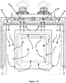
Figure 1 ; is a frontal view of the semi-mounted state of the developed cooking device. -
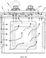
Figure 2 ; is a frontal view of another semi-mounted state of the developed cooking device. -
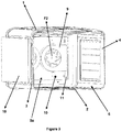
Figure 3 ; is a perspective view of the semi-mounted state of the developed cooking device. -
Figure 4 ; is a frontal view of another semi-mounted state of the developed cooking device. -
Figure 5 ; is a perspective view of a guidance element comprised within the developed cooking device. -
Figure 6 ; is a perspective view of an air duct comprised within the developed cooking device. -
Figure 7 ; is a perspective view of a baffle element comprised within the developed cooking device. -
Figure 8 ; is a side sectional view of semi-mounted state of the developed cooking device. -
Figure 9 ; is a frontal view of the semi-mounted state of the developed cooking device in another embodiment. -
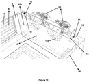
Figure 10 ; is a detailed perspective view of the developed cooking device. -
Figure 11 - 22 ; top sectional view of the air flows inside the device in the exemplary embodiments of the developed cooking device. - All the parts illustrated in figures are individually assigned a reference numeral and the corresponding terms of these numbers are listed below:
First fan (F1) Second fan (F2) Support element (H1) Motor (H2) Top wall (1) Bottom wall (2) First side wall (3) Second side wall (4) Rear wall (5) Opening (5a) Placement opening (6) Holding member (7) Second hole (8) Guidance element (9) Body (9a) First passage (9b) Second passage (9c) Air duct (10) Lateral wall (10a) Baffle element (11) Air passage space (11a) Heater (12) Flap (13) Third passage (14) Baffle (15) First hole (15a) Third hole (15b) Circulation distance (16) - Various cooking devices for cooking a food are already in use. These cooking devices basically provide to cook the food by providing heat to the food to be cooked contained within the vessel. In particular, for cooking devices, such as an oven, in which the cooking process is performed in the cooking compartment comprised therein, hot air should reach to the food equally in order to perform the cooking process efficiently. Within this context, with the present invention, there is developed a cooking device which provides equal heat distribution for the food to be cooked and in which more than one food is able to be cooked at the same time.
- The cooking device developed by the present invention, exemplary views of which are illustrated in
Figures 1-4 , comprises at least a top wall (1); at least a bottom wall (2) provided opposite to the top wall (1); at least a first side wall (3) provided between the top wall (1) and the bottom wall (2); at least a second side wall (4) provided opposite to the first side wall (3); at least a rear wall (5); at least a cooking compartment formed by these walls, in which the cooking process is performed; at least a placement opening (6) provided opposite to the rear wall (5) and which enables to place food to the cooking compartment; and at least two holding members (7) (preferably at least four at the opposite side walls) provided one above the other such that at least two vessels is able to be provided one above the other in the cooking compartment at the same time, which enable to place the vessel (e.g. a tray) containing the food to be cooked in the cooking compartment in a suspended way and are preferably provided at the side of the first side wall (3) and/or the second side wall (4) facing the cooking compartment (4) (said holding member (7) may be an external component attached to the cooking compartment via a connection element (e.g. screw, nail, adhesives etc.) and/or it may be in a structure formed on the second side wall (4), which is integrated with the related side wall). The cooking device developed by the present invention also comprises: at least an opening (5a) provided at the rear wall (5a); at least a baffle (15) which closes said opening (5a), and has at least two first holes (15a) for air passage which are provided side by side such that at least one of them is close to the first side wall (3) and at least the other is close to the second side wall (4), and which is preferably detachable to and from the rear wall (5); at least an air duct (10) provided such that it surrounds the first side wall (3), the rear wall (5) and the second side wall (4) at the outer sides of the first side wall (3), the rear wall (5) and the second side wall (4) that do not face the cooking compartment, and that an air circulation space is formed between the duct and first side wall (3), the rear wall (5) and the second side wall (4), an exemplary view of which is provided infigure 6 , and which comprises at least three lateral sides (10a) (these lateral walls (10a) may both be one-piece structure and be multi-piece structure connected to each other for manufacturing ease) which surround said outer sides of the first side wall (3), the rear wall (5) and the second side wall (4); at least a first fan (F1) (preferably an axial fan) which is provided between the rear wall (5) and the air duct (10) so as to correspond to the first hole (15a) that is close to the first side wall (3), and which draws the air inside the cooking compartment via said first hole (15a) when the propeller comprised therein is activated to rotate around an axis; at least a second fan (F2) (preferably an axial fan) which is provided between the rear wall (5) and the air duct (10) so as to correspond to the first hole (15a) that is close to the second side wall (4), and which draws the air inside the cooking compartment via said first hole (15a) when the propeller comprised therein is activated to rotate around an axis; at least two movement arrangements, one for each fan, enabling said rotational movement of the first fan (F1) and the second fan (F2) when energised by an energy source; at least two guidance elements (9), at least one for guiding the air drawn by the first fan (F1) from the cooking compartment to the air circulation space that is between the first side wall (3) and the air duct (10), at least another for guiding the air drawn by the second fan (F2) from the cooking compartment to the air circulation space that is between the second side wall (4) and the air duct (10), and each of which is provided so as to have a circulation distance (16) (preferably more than 10mm) between them and the baffle (15); at least two annular heaters (12) which provide to heat the air drawn by the fans from the cooking compartment, and are provided so as to surround each fan; at least a thermometer preferably provided on the rear wall (5) and measuring temperature of the cooking compartment; at least a control unit in connection with the thermometer, which arranges operation of the fans and the heaters according to a cooking option determined by the user and measured temperature values; and plurality of second holes (8) provided on both the first side wall (3) and the second side wall (4), which provide the air, drawn by the fans and transmitted to the air circulation space that is between the side walls and the air duct (10) after heated via the heaters (12), to return to the cooking compartment, and which is placed, preferably, such that, when the vessels containing food to be cooked are attached to the holding members (7), air release is occurred towards the middle of the of the two holding members (7) so as to correspond to the middle of the distance formed between the bottom surface of one of the vessels and the top surface of the other vessel, and towards the top of the top holding member (7) and bottom of the bottom holding member (7). - In an exemplary embodiment of the invention, foods to be cooked are placed to the trays and the trays are placed in the cooking compartment via the holding members (7). The control unit arranges operation and waiting states of the fans and the heaters according to selected cooking option. For example, both of the heaters (12) and accordingly both of the first fan (F1) and the second fan (F2) are operated since temperature at the cooking compartment is quite law for cooking process at the beginning of the cooking option. When operated in this way, both the first fan (F1) and the second fan (F2) draw air from the cooking compartment and the air drawn is heated by the heaters (12) around the fans. The air drawn by the first fan (F1) and heated is prevented to return to the cooking compartment through the first hole (15a) via the guidance element (9) in connection with the first fan (F1) to guide it to the air circulation space between the first side wall (3) and the air duct (10). Similarly, the air drawn by the second fan (F2) and heated is prevented to return to the cooking compartment through the first hole (15a) via the guidance element (9) in connection with the second fan (F2) to guide it to the air circulation space between the second side wall (4) and the air duct (10). In this way, it is also prevented for the air drawn by both of the fans and heated to mix each other. Also, heated air provided within the air circulation spaces that are between the side walls and the air duct (10) passes through the second holes (8) on the side walls and returns to the cooking compartment, and thus it reaches to the foods at the trays. Due to the fact that the second holes (8) are provided such that they transmit hot air both to the top and bottom of the trays, equal cooking of the foods in the trays is provided. Moreover, cooking efficacy is increased and also equal cooking of the multiple foods simultaneously is provided by sending the heated air to the foods through the side walls. By preventing the air drawn and guided by the fans to mix each other, homogenous temperature distribution within the cooking compartment is obtained. Also, thanks to said circulation distance (16), in case one of the fans operates and the other does not, the operating fan is also able to draw the air inside the cooking compartment through the non-operating fan.
- In an alternative embodiment illustrated in
figure 5 , each of the guidance elements (9) comprised within the developed cooking device preferably comprises: at least a body (9a) within which the fan and the heater (12) are provided; at least a first passage (9b) provided at the side of the body (9a) facing the first hole (15a), which provides the air, drawn through the first hole (15a) from the cooking compartment with the rotation of the propeller comprised within the fan, to reach inside the body (9a) and accordingly to the heater (12); and at least a second passage (9c) which provides to guide the air, passing through the first passage (9b) and reaching to the body (9a), to the side edge from the body (9a). In this embodiment, the first fan (F1) and the second fan (F2) are provided inside the body (9a) of the guidance element (9), and the heaters (12) are provided inside the body (9a) so as to surround the related fan. In addition, the guidance element (9), in which the first fan (F1) is provided, is between the rear wall (5) and the air duct (10) such that the first passage (9b) comprised within this guidance element (9) corresponds to the first hole (15a) that is close to the first side wall (3). Moreover, the guidance element (9), in which the second fan (F2) is provided, is between the rear wall (5) and the air duct (10) such that the first passage (9b) comprised within this guidance element (9) corresponds to the first hole (15a) that is close to the second side wall (4). By this kind of placement, air drawn from the cooking compartment is able to be guided directly to the related side wall without returning to the cooking compartment, and thus it is prevented to negatively affect the airflow inside the compartment (e.g. back draft to the cooking compartment and short-circuit flows) and cooking efficacy may be increased more. Additionally, because of the fact that the fans and the heaters (12) are totally embodied by the guidance element (9), it is prevented for positive air pressures, formed by the fans while operating, to mix each other. In this embodiment, preferably, said first passage (9b) has a circular section, and its diameter is preferably smaller than the diameter of the propellers of the fans. By this way, it may be provided for air to reach to the air circulation spaces with higher pressure by drawing it with higher flow rate, and accordingly to reach to the cooking food in more efficient manner by exiting through the second holes (8) with higher speed. - In another exemplary embodiment of the invention provided in
figure 7 andfigure 8 , the developed cooking device preferably comprises at least two baffle elements (11) provided between the rear wall (5) and the air duct (10), at least one for each guidance elements (9), which prevent the air, drawn by the fans from the cooking compartment and exited from the guidance element (9), to return to the cooking compartment (in other words, which provide the air to directly reach to the air circulation space that is between the side edges and the air duct (10)), and which are in the form of a plate rod that has at least an air passage space (11a) on it. The width of the air passage space (11a) comprised within said baffle element (11) is preferably the same with the width of the second passage (9c) comprised within the guidance element (9), and the baffle element (11) is provided such that the air passage space (11a) exactly corresponds to the second passage (9c). By this way, unwanted air flows are prevented to a large extent. Particularly, return of the air, drawn by the fans from the cooking compartment and exited from the guidance element (9), to the cooking compartment is able to be efficiently prevented. - In another embodiment of the invention illustrated in
figure 8 , each movement arrangement comprised within the developed cooking device preferably comprises: at least a motor (H2) in connection with said energy source, which provides the rotation of the propellers with the energy received from the energy source, and at least a support element (H1) which provides to rigidly fix the motor (H2) to the cooking device, on which the motor (H2) is provided and which is preferably provided on the air duct (10). - In another preferred embodiment of the invention illustrated in
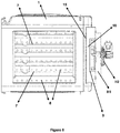
figure 9 andfigure 10 , the cooking device comprises: at least two third passages (14) provided on the rear wall (5) such that at least one of them is provided between the first fan (F1) and the first side wall (3), and that at least another one of them is between the second fan (F2) and the second side wall (4) (preferably side of the baffle elements (11) that does not facing the fans); at least two third holes (15b), at least one for each third passages (14), provided at said baffle (15) so as to correspond to the third passages (14); and at least two flaps (13), at least one for each third passages (14), which have an opened position to allow air passage through said third passage (14) and a closed position to prevent air passage through the third passage (14), which control, by means of these opened/closed positions, the passage of air between the air circulation space that is between the rear wall (5) and the air duct (10) and the air circulation space that is between the side walls and the air duct (10), which are preferably connected to the rear wall (5) via at least a hinge, and which are able to pass between these opened/closed positions by rotating at this hinge axis. While in opened position, said flaps (13) are provided such that they have a predetermined angle (preferably an acute angle or right angle with the third passage (14)) with said third passage (14) (or with the rear wall (5)). Cooking compartment air drawn from the first holes (15a) by means of the flaps (13) is also able to be sent to the cooking compartment through the third holes (15b) on the baffle (15) in accordance with the needs, as well as the side walls. In this manner, circulation directions of the air inside the cooking device are increased and accordingly, it is able to be provided to cook simultaneously same or different foods contained in a plurality of vessels in an efficient manner. - In another alternative embodiment of the invention, preferably, width of said second holes (8) may be different from each other. For example, width of the second holes (8) may increase from the opening (5a) towards the rear wall (5) in an embodiment while they may decrease in another embodiment. Yet in another embodiment, as illustrated in
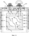
figure 8 , width of the second holes (8) may decrease towards the middle portion such that width of the second holes (8) that is close to the opening (5a) and to the rear wall (5) is above the width of the second holes (8) at the middle portion. - Operation method of the cooking device developed by the present invention comprises the steps of: selecting, by the user, one of the plurality of cooking options which are pre-saved in the control unit; detecting required temperature value within the cooking department according to the selected option; then operating at least one of the heaters (12) and fans; and by this way, initiating both the heating process and the cooking process with the circulation of air that is in the cooking compartment. As exemplified in
figures 11 -13 , when the heaters (12) are active, one or two of the fans may be operated together. Manners of application of the developed operation method is shown in table - 1, wherein "+" indicates operating states of the related component (active), and "-" indicates non-operating states of the related component.Table - 1 First fan (F1) + + - + + + - Second fan (F2) + - + + + - + Heater in connection with the first fan (F1) + + - + - + + Heater in connection with the second fan (F2) + - + - + + + - For example, when only the first fan (F1) is operated together with the heaters, air inside said cooking compartment reaches to the first fan (F1) by passing to the air circulation space through the first holes (15a), and the second holes (8) which are at the second side wall (4). Also, the air heated via the heaters (12) passes to the inside of the cooking compartment through the second holes (8) on the first side wall (3), thus the air circulation is provided. Again, when only the second fan (F2) is operated together with the heaters (12), the air inside said cooking compartment reaches to the second fan (F2) by passing to the air circulation space through the first holes (15a), and second holes (8) on the first side wall (3). The air heated by the heaters (12) passes to the cooking compartment through the second holes (8) provided on the second side wall (4), and thus the air circulation is provided by this way. By this manner, energy consumption is decreased by shortening the pre-heating process of the cooking device, time-saving is provided and an efficient and effective cooking device is obtained. When both the first fan (F1) and the second fan (F2) is operated together with the heaters (12), the air inside the cooking compartment is drawn separately by both of the fans and does not mix with each other. In this embodiment, the air drawn by the first fan (F1) is transmitted to the air circulation space that is between the first side wall (3) and the air duct (10) by being heated via the heater (12) around the first fan (F1); and the air drawn by the second fan (F2) is transmitted to the air circulation space that is between the second side wall (4) and the air duct (10) by being heated via the heater (12) around the second fan (F2) and is transmitted to the cooking department through the second holes (8) provided on the side walls. In a preferred embodiment, when a heater (12) is active, the fan in connection with this heater (12) is also active, and if the heater (12) is not active, it is passivized by ceasing the rotation of the propeller comprised within the fan with which it is in connection. In other words, the first fan (F1) and the heater (12) provided around the first fan (F1), and the second fan (F2) and the heater (12) around the second fan (F2) are operated simultaneously in themselves. Yet in another exemplary embodiment, only one heater (12) may also be operated while the propeller comprised within both of the fans is rotated. Yet in another preferred embodiment, while the heaters (12) do not operate, the fans may be operated for predetermined times respectively and/or together, and by this way an equal heat distribution may be obtained within the cooking compartment. In the developed operation method, the heaters (12) and the fans may be controlled independently from each other according to the selected cooking option. In an exemplary embodiment, operation times of the fans and the heaters (12) may be equal. Yet in another exemplary embodiment, operation times of the first fan (F1) and the heater (12) in connection with the first fan (F1) are equal, and operation times of the second fan (F2) and the heater (12) in connection with the second fan (F2) are equal, and the operation time of the first fan (F1) and the heater (12) in connection with the first fan (F1) is longer than the operation time of the second fan (F2) and the heater (12) in connection with the second fan (F2). Yet in another exemplary embodiment, operation times of the first fan (F1) and the heater (12) in connection with the first fan (F1) are equal, and operation times of the second fan (F2) and the heater (12) in connection with the second fan (F2) are equal, and the operation time of the first fan (F1) and the heater (12) in connection with the first fan (F1) is shorter than the operation time of the second fan (F2) and the heater (12) in connection with the second fan (F2). In another alternative embodiment, operation times of the first fan (F1) and the second fan (F2) are equal, and the operation times of the heaters (12) are equal, and the operation time of the first fan (F1) and the second fan (F2) is longer than the operation time of the heaters (12). Yet in another alternative embodiment, operation times of the first fan (F1) and the second fan (F2) are equal, and are longer than the operation time of the heater (12) in connection with the first fan (F1) and the operation time of the heater (12) in connection with the second fan (F2). In this embodiment, operation time of the heater (12) in connection with the first fan (F1) is also longer than the operation time of the heater (12) in connection with the second fan (F2). In this embodiment, alternatively, operation time of the heater (12) in connection with the first fan (F1) may also be shorter than the operation time of the heater (12) in connection with the second fan (F2).
- Exemplary embodiments of the developed operation method may be summarised as follows:
When the heaters (12) are operating (when active), if the operation time is assigned as X1 for the first fan (F1), X2 for the second fan (F2), Y1 for the heater (12) in connection with the first fan (F1), Y2 for the heater (12) in connection with the second fan (12), correlation between these times may be X1=X2=Y1=Y2, X1=Y1>X2=Y2, X2=Y2>X1=Y1, X1=X2>Y1>Y2, X1=X2>Y2>Y1. - Operation method developed according to the present invention also preferably comprises the steps of: stopping the heaters (12) when the required temperature value within the cooking compartment is obtained according to the selected option; continuing the temperature measurement of the cooking compartment with a predetermined period via a thermometer; and when the temperature of the cooking compartment is below said predetermined temperature value for a predetermined time, re-operating at least one of the heaters (12). The table summarising the operation practices of the fans in the case where the heaters are not operating is given at table - 2.
Table - 2 First fan (F1) + + - - Second fan (F2) + - + - Heater in connection with the first fan (F1) - - - - Heater in connection with the second fan (F2) - - - - - In the case where the heaters (12) are not operating, alternatively, preferably there may be a predetermined waiting time (e.g. 10 seconds) for the fans. In this embodiment, operation times of the first fan (F1) and the second fan (F2) may be equal to each other and the waiting time, or be shorter than the waiting time. Yet in another exemplary embodiment, operation time of the first fan (F1) may be longer than the operation time of the second fan (F2), and operation time of the second fan (F2) may be longer than the waiting time. In another exemplary embodiment, operation time of the second fan (F2) may be longer than the operation time of the first fan (F1), and operation time of the first fan (F1) may be longer than the waiting time.
- Exemplary embodiments of the developed operation method when the heaters (12) are not operating may be summarised as follows:
If the operation time is assigned as X3 for the first fan (F1), X4 for the second fan (F2), and said waiting time is assigned as T, correlation between these times may be X3=X4>T, X3>X4>T, X4>X3>T and T>X3=X4. For example, the first fan (F1) is stopped after it is operated for X3=1 minutes, and the second fan (F2) is operated for X4=1 minutes after waiting time of T=10 seconds. The second fan (F2) is stopped after it is operated for X4=1 minutes, and the first fan (F1) is re-operated for X3=1 minutes after waiting time of T=10 seconds. Moreover, the fans may completely be closed and be in a passive state for T waiting time. - In another embodiment of the cooking device developed according to the present invention, the operation method comprises the steps of: selecting, by the user, one of the plurality of cooking options which are pre-saved in the control unit; detecting required temperature value within the cooking department according to the selected option; arranging the opened/closed positions of the flap (13) by operating at least one of the heaters (12) and the fans; and by this way, initiating both the heating process and the cooking process with the circulation of air that is in the cooking compartment. As exemplified in
figure 14 - figure 22 , in this embodiment, for example the flaps (13) are in opened position, and while the first fan (F1) (preferably together with the heater (12) with which it is in connection) is operating, the second fan (F2) (and preferably the heater (12) with which the second fan (F2) is in connection) is passive. In this embodiment, the air inside the cooking compartment is drawn by the first fan (F1) through the first holes (15a) and the third hole (15b) that is close to the second fan (F2), and returned to the cooking compartment through the third hole (15b) that is close to the first fan (F1). In this opened position of the flaps (14), there is no air passage at the air circulation space that is between the side walls and the air duct (10). Yet in another embodiment, for example the flaps (13) are in the opened position and the second fan (F2) (preferably together with the heater (12) with which it is in connection) is in operation, and the first fan (F1) (preferably together with the heater (12) with which the first fan (F1) is in connection) is passive. In this embodiment, air inside the cooking compartment is drawn by the second fan (F2) through the first holes (15a) and the third hole (15b) that is close to the first fan (F1), and returned to the cooking compartment through the third hole (15b) that is close to the second fan (F2). In this opened position of the flaps (14), there is no air passage at the air circulation space that is between the side walls and the air duct (10). In another exemplary embodiment where the flaps are opened, both of the fans (and preferably the heaters (12) with which the fans are in connection) may be in operation. In this case, the air inside the cooking compartment is drawn by both of the fans through the first holes (15a) without being mixed each other, and returned to the cooking compartment via the third holes (15b). In another exemplary embodiment, the flap (13) that is close to the first fan (F1) may be in the opened position, and the flap (13) that is close to the second fan (F2) may be in the closed position. In this embodiment, the first fan (F1) (preferably together with the heater (12) with which it is in connection) is in operation, and the second fan (F2) (preferably together with the heater (12) with which the second fan (F2) is in connection) is passive. In this case, the air inside the cooking compartment passes to the air circulation space through the first holes (15a), and the second holes (8) that are close to the second side wall (4) via the first fan (F1), and returns to the cooking compartment via the third hole (15b) that is close to the first fan (F1). Yet in another exemplary embodiment, the flap that is close to the first fan (F1) may be in the opened position, and the flap (13) that is close to the second fan (F2) may be in the closed position. In this embodiment, the second fan (F2) (preferably together with the heater (12) with which it is in connection) is in operation, and the first fan (F1) (preferably together with the heater (12) with which the first fan (F1) is in connection) is passive. In this case, air inside the cooking compartment is transmitted to the air circulation space that is between the second side edge (4) and the air duct (10) through the second fan (F2) by passing through the first holes (15a) and the third hole (15b) that is close to the first fan (F1) via the second fan (F2), and returns to the cooking compartment via the second holes (8) provided at the second side edge (4). In another alternative embodiment where the flap (13) that is close to the first fan (F1) is in the opened position and the flap (13) that is close to the second fan (F2) is in the closed position, both of the fans (and preferably the heaters (12) with which the fans are in connection) may be in operation. In this case, air inside the cooking compartment is drawn by both of the fans through the first holes (15a) without being mixed each other, and returned to the cooking compartment via the third hole (15b) that is close to the first fan (F1) and the second holes (8) provided at the second side wall (4). In another exemplary embodiment, the flap (13) that is close to the second fan (F2) may be in the opened position, and the flap (13) that is close to the first fan (F1) may be in the closed position. In this embodiment, the first fan (F1) (preferably together with the heater (12) with which it is in connection) is in operation, and the second fan (F2) (and preferably together with the heater (12) with which the second fan (F2) is in connection) is passive. In this case, air inside the cooking compartment reaches to the first fan (F1) through the first holes (15a) and the third hole (15b) that is close to the second fan (F2) via the first fan (F1), and returns to the cooking compartment via the second holes (8) located on the first side wall (3) after being transmitted to the air circulation space that is between the first side wall (3) and the air duct (10). Yet in another exemplary embodiment, the flap (13) that is close to the second fan (F2) may be in the opened position, and the flap (13) that is close to the first fan (F1) may be in the closed position. In this embodiment, the second fan (F2) (preferably together with the heater (12) with which it is in connection) is in operation, and the first fan (F1) (and preferably the heater (12) with which the first fan (F1) is in connection) is passive. In this case, the air within the cooking compartment passes through the first holes (15a), and the second holes (8) that are on the first side wall (3) via the second fan (F2), and returns to the cooking compartment through the second fan (F2) via the third hole (15b) that is close to the second fan (F2). In another alternative embodiment where the flap (13) that is close to the second fan (F2) is in the opened position and the flap (13) that is close to the first fan (F1) is in the closed position, both of the fans (and also, preferably the heaters (12) with which the fans are in connection) may be in operation. In this case, the air inside the cooking compartment is drawn through the first holes (15) via both of the fans without being mixed each other, and returns to the cooking compartment via the third hole (15b) that is close to the second fan (F2) and the second holes (8) provided on the first side wall (3). In the developed operation method, the heaters (12), fans and the flaps (13) is able to be controlled independently according to the selected cooking option. In an exemplary embodiment, operation times of the fans and the heaters (12) may be equal. In this embodiment, the times when the flaps (13) are in the closed position may be equal or different. For example, operation times of the heaters (12) and the fans may be longer than the time when the flap (13) that is close to the first fan (F1) is in the closed position, and the time when the flap (13) that is close to the first fan (F1) is in the closed position may be longer than the time when the flap (13) that is close to the second fan (F2) is in the closed position. In another embodiment, operation times of the heaters (12) and the fans may be longer than the time when the flap (13) that is close to the second fan (F2) is in the closed position, and the time when the flap (13) that is close to the second fan (F2) is in the closed position may be longer than the time when the flap (13) that is close to the first fan (F1) is in the closed position. Yet in another embodiment, times when the flaps (13) are in the closed position may be equal and they may be longer or shorter than the operation times of the heaters (12) and the fans. In another embodiment, the time when the flap (13) that is close to the first fan (F1) is in the closed position may be longer than the time when the flap (13) that is close to the second fan (F2) is in the closed position, and the time when the flap (13) that is close to the second fan (F2) is in the closed position may be longer than the operation times of the heaters (12) and the fans. In another alternative embodiment, the time when the flap (13) that is close to the second fan (F2) is in the closed position may be longer than the time when the flap (13) that is close to the first fan (F1) is in the closed position, and the time when the flap (13) that is close to the first fan (F1) is in the closed position may be longer than the operation times of the heaters (12) and the fans. - Operation method developed according to the present invention also preferably comprises the steps of: stopping the heaters (12) when the required temperature value within the cooking compartment is obtained according to the selected option; continuing the temperature measurement of the cooking compartment with a predetermined period via the thermometer; and when the temperature of the cooking compartment is below said predetermined temperature value for a predetermined time, re-operating at least one of the heaters (12). In the case where the heaters (12) are not in operation, alternatively, preferably, the first fan (F1) and the second fan (F2) may be operated for equal or different times. Similarly, the flaps (13) may also be in the closed position for equal or different times. Operation times of the fans and the time when the flaps (13) are in the closed position are different.
- Exemplary embodiments of the developed operation method using the flaps (13) may be summarised as follows:
When the heaters (12) are active, the fans operate together. If this time when the fans and the heating elements operate together is Q, the flap (13) that is close to the first fan (F1) may be opened for a T1 time, and the flap (13) that is close to the second fan (F2) may be opened for a T2 time. In this case, operation correlation between the flaps (13) and the fans may be Q>T1>T2, Q>T2>T1, Q>T1=T2, T1>T2>Q, T2>T1>Q, T1=T2>Q. In addition, the Q heating time is the time when the fans and the heaters (12) operate together, and as explained above, within this period the first fan (F1), the second fan (F2) and the heaters (12) may be operated with said algorithms for the Q time. - When the heaters (12) are passive (when not operating), the first fan (F1) may be operated for a X11 time, the second fan (F2) may be operated for a Y11 time, the flap (13) that is close to the first fan (F1) may be operated for a T11 time, the flap (13) that is close to the second fan (F2) may be operated for a T22 time. In this case, operation correlation between the flaps (13) and the fans when the heaters (12) are closed is summarised in table - 3.
Table - 3 X11> Y11> T11> T22 Y11> X11> T11> T22 X11= Y11> T11> T22 X11> Yl1> T22> T11 Y11> X11> T22> T11 X11= Y11> T22> T11 X11> Y11> T11= T22 Y11> X11> T11>=T22 X11= Y11> T11= T22 T11> T22> X11> Y11 T22> T11> X11> Y11 T11= T22> X11> Y11 T11> T22> Y11> X11 T22> T11> Y11> X11 T11= T22> Y11> X11 T11> T22> X11-Y11 T22> T11> X11-Y11 T11= T22> X11=Y11 - Thanks to the cooking device and the operation method developed by the present invention, an equal heat distribution within the cooking compartment is obtained and an efficient cooking process is able to be performed in this manner. Moreover, time may be saved by shortening the pre-heating process. In addition, it may be provided to cook same or different foods in a plurality of vessels simultaneously in an efficient manner.
Claims (14)
- A cooking device comprising at least a top wall (1); at least a bottom wall (2) provided opposite to the top wall (1); at least a first side wall (3) provided between the top wall (1) and the bottom wall (2); at least a second side wall (4) provided opposite to the first side wall (3); at least a rear wall (5); at least a cooking compartment formed by these walls, in which the cooking process is performed; at least a placement opening (6) provided opposite to the rear wall (5) and which enables to place food to the compartment; and at least two holding members (7) provided one above the other such that at least two vessels is able to be provided one above the other in the cooking compartment at the same time, and which enable to place the vessel containing the food to be cooked in the cooking compartment in a suspended way, characterized in that the cooking device comprises:- at least an opening (5a) provided at the rear wall (5a);- at least a baffle (15) which closes said opening (5a), and has at least two first holes (15a) for air passage which are provided side by side such that at least one of them is close the first side wall (3) and at least the other is close the second side wall (4);- at least an air duct (10) provided such that it surrounds the first side wall (3), the rear wall (5) and the second side wall (4) at the outer sides of the first side wall (3), the rear wall (5) and the second side wall (4) that do not face the cooking compartment, and that an air circulation space is formed between the duct and the first side wall (3), the rear wall (5) and the second side wall (4), and which comprises at least three lateral sides (10a) which surround said outer sides of the first side wall (3), the rear wall (5) and the second side wall (4);- at least a first fan (F1) which is provided between the rear wall (5) and the air duct (10) so as to correspond to the first hole (15a) that is close to the first side wall (3), and which draws the air inside the cooking compartment via said first hole (15a) when the propeller comprised therein is activated to rotate around an axis;- at least a second fan (F2) which is provided between the rear wall (5) and the air duct (10) so as to correspond to the first hole (15a) that is close to the second side wall (4), and which draws the air inside the cooking compartment via said first hole (15a) when the propeller comprised therein is activated to rotate around an axis;- at least two movement arrangements, one for each fan, enabling said rotational movement of the first fan (F1) and the second fan (F2) when energised by an energy source;- at least two guidance elements (9), at least one for guiding the air drawn by the first fan (F1) from the cooking compartment to the air circulation space that is between the first side wall (3) and the air duct (10), at least another for guiding the air drawn by the second fan (F2) from the cooking compartment to the air circulation space that is between the second side wall (4) and the air duct (10), and each of which is provided so as to have a circulation distance (16) between them and the baffle (15);- at least two annular heaters (12) which provide to heat the air drawn by the fans from the cooking compartment, and are provided so as to surround each fan;- at least a thermometer measuring temperature of the cooking compartment;- at least a control unit in connection with the thermometer, which arranges operation of the fans and the heaters according to a cooking option determined by the user and measured temperature values; and- plurality of second holes provided on both the first side wall (3) and the second side wall (4), which provide the air, drawn by the fans and transmitted to the air circulation space that is between the side walls and the air duct (10) after being heated via the heaters (12), to return to the cooking compartment.
- A cooking device according to Claim 1, characterized in that each of the guidance elements (9) comprises:- at least a body (9a) within which the fan and the heater (12) are provided;- at least a first passage (9b) provided at the side of the body (9a) facing the first hole (15a), which provides the air, drawn through the first hole (15) from the cooking compartment with the rotation of the propeller comprised within the fan, to reach inside the body (9a) and accordingly to the heater (12); and- at least a second passage (9c) which provides to guide the air, passing through the first passage (9b) and reaching to the body (9a), to the side edge from the body (9a).
- A cooking device according to Claim 1, characterized in that the cooking device comprises: at least two baffle elements (11) provided between the rear wall (5) and the air duct (10), at least one for each guidance element (9), which prevent the air, drawn by the first fan (F1) and the second fan (F2) from the cooking compartment and exited from the guidance element (9), to return to the cooking compartment, and which are in the form of a plate rod that has at least an air passage space (11a) on it.
- A cooking device according to Claim 1, characterized in that the cooking device comprises:- at least two third passages (14) provided on the rear wall (5) such that at least one of them is between the first fan (F1) and the first side wall (3), and that at least another one of them is between the second fan (F2) and the second side wall (4);- at least two third holes (15b), at least one for each third passages (14), provided at said baffle (15) so as to correspond to the third passages (14); and- at least two flaps (13), at least one for each third passages (14), which have an opened position to allow air passage through said third passage (14) and a closed position to prevent air passage through the third passage (14), which control, by means of these opened/closed positions, the passage of air between the air circulation space that is between the rear wall (5) and the air duct (10) and the air circulation space that is between the side walls and the air duct (10), and which are able to pass between these opened/closed positions by rotating around an axis.
- A cooking device according to Claim 4, characterized in that in the opened position, the flaps (13) are provided such that they have a predetermined angle with the third passage (14).
- A cooking device according to Claim 1, characterized in that said second holes (8) are provided such that, when the vessels containing food to be cooked are attached to the holding members (7), air release is occurred towards the middle of the two holding members (7) so as to correspond to the middle of the distance formed between the bottom surface of one of the vessels and the top region of the other vessel, and towards the top of the top holding member (7) and bottom of the bottom holding member (7).
- An operation method for a cooking device according to any of the preceding claims, characterized in that the method comprises the steps of: selecting, by the user, one of the plurality of cooking options which are pre-saved in the control unit; detecting required temperature value within the cooking department according to the selected option; then operating at least one of the heaters (12) and the fans, and by this way, initiating both the heating process and the cooking process with the circulation of air that is in the cooking compartment; stopping the heaters (12) when the required temperature value within the cooking compartment is obtained according to the selected option; continuing the temperature measurement of the cooking compartment with a predetermined period via the thermometer; and when the temperature of the cooking compartment is below said predetermined temperature value for a predetermined time, re-operating at least one of the heaters (12); when a heater (12) is active, also activating the fan in connection with this heater (12); and if the heater (12) is not active, passivizing this fan by ceasing the rotation of the propeller comprised within the fan with which it is in connection; and that there is a predetermined waiting time for the first fan (F1) and/or the second fan (F2) in the case that the heaters (12) are not operating; that the fans are operated respectively and/or together for the predetermined times while the heating elements (12) are not operating; and that the heaters (12) and the fans are controlled independently from each other according to the selected cooking option.
- An operation method according to Claim 7, characterized in that the method comprises the step of arranging the opened/closed positions of the flaps (13), as well, when the first fan (F1) and/or the second fan (F2) operates.
- An operation method according to Claim 7, characterized in that the method comprises the steps of:- operating only the first fan (F1) together with the heaters (12), and by this way, enabling the air inside said cooking compartment to reach to the first fan (F1) by passing to the air circulation space through the first holes (15a), and the second holes (8) which are at the second side wall (4); sending the air heated by the heaters (12) to the cooking compartment through the second holes (8) provided on the first side wall (3)
or- operating only the second fan (F2) together with the heaters (12), and by this way, enabling the air inside said cooking compartment to reach to the second fan (F2) by passing to the air circulation space through the first holes (15a), and second holes (8) on the first side wall (3); sending the air heated by the heaters (12) to the cooking compartment through the second holes (8) provided on the second side wall (4). - An operation method according to Claim 7, characterized in that the operation times of the first fan (F1) and the heater (12) in connection with the first fan (F1) are equal; that the operation times of the second fan (F2) and the heater (12) in connection with the second fan (F2) are equal; and that the operation time of the first fan (F1) and the heater (12) in connection with the first fan (F1) is longer or shorter than the operation time of the second fan (F2) and the heater (12) in connection with the second fan (F2).
- An operation method according to Claim 7, characterized in that the operation times of the first fan (F1) and the second fan (F2) are equal and- that this time is longer than operation time of the heater (12) in connection with the first fan (F1) and the operation time of the heater (12) in connection with the second fan (F2), and the operation time of the heater (12) in connection with the first fan (F1) is longer than the operation time of the heater in connection with the second fan (F2)
or- that this time is longer than operation time of the heater (12) in connection with the first fan (F1) and the operation time of the heater (12) in connection with the second fan (F2), and the operation time of the heater (12) in connection with the first fan (F1) is shorter than the operation time of the heater (12) in connection with the second fan (F2)
or- that the operation times of the heaters (12) are equal, and the operation time of the first fan (F1) and the second fan (F2) is longer than the operation time of the heaters (12). - An operation method according to Claim 8, characterized in that the method comprises the steps of: switching the flaps (13) to the opened position;- making the first fan (F1) operable and passivizing the second fan (F2), and by this way, drawing the air inside the cooking compartment by the first fan (F1) through the first holes (15a) and the third hole (15b) that is close to the second fan (F2), and returning it to the cooking compartment through the third hole (15b) that is close to the first fan (F1)
or- making the second fan (F2) operable and passivizing the first fan (F1), and by this way, drawing the air inside the cooking compartment by the second fan (F2) through the first holes (15a) and the third hole (15b) that is close to the first fan (F1), and returning it to the cooking compartment through the third hole (15b) that is close to the second fan (F2)
or- making both the first fan (F1) and the second fan (F2) operable, and by this way, drawing the air inside the cooking compartment by both of the fans through the first holes (15a) without being mixed with each other, and returning it to the cooking compartment through the third holes (15b). - An operation method according to Claim 8, characterized in that the method comprises the steps of: switching the flap (13), which is close to the first fan (F1), to the opened position;- switching the flap (13), which is close to the second fan (F2), to the closed position; making the first fan (F1) operable and passivizing the second fan (F2), and by this way, passing the air inside the cooking compartment by the first fan (F1) through the first holes (15a), and the second holes (8) provided on the second side wall (4), and returning it to the cooking compartment through the third hole (15b) that is close to the first fan (F1)
or- switching the flap (13), which is close to the second fan (F2), to the closed position; making the second fan (F2) operable and passivizing the first fan (F1), and by this way, passing the air inside the cooking compartment by the second fan (F2) through the first holes (15a), and the third hole (15b) that is close to the first fan (F1), transmitting it to the air circulation space provided between the second side wall (4) and the air duct (10), and returning it to the cooking compartment through the second holes (8) provided on the second side wall (4)
or- switching the flap (13), which is close to the second fan (F2), to the closed position; making both the first fan (F1) and the second fan (F2) operable, and by this way, drawing the air inside the cooking compartment by both of the fans through the first holes (15a) without being mixed each other and returning it to the cooking compartment through the third hole (15b) that is close to the first fan (F1), and the second holes (8) provided on the second side wall (4). - An operation method according to Claim 8, characterized in that the method comprises the steps of: switching the flap (13), which is close to the second fan (F2), to the opened position;- switching the flap (13), which is close to the first fan (F1), to the closed position; making the first fan (F1) operable; passivizing the second fan (F2), and by this way, conveying the air inside the cooking compartment to the first fan (F1) through the first holes (15a) via the first fan (F1) and the third hole (15b) that is close to the second fan (F2), transmitting it to the air circulation space provided between the first side wall (3) and the air duct (10), and returning it to the cooking compartment through the second holes (8) provided on the first side wall (3)
or- switching the flap (13), which is close to the first fan (F1), to the closed position; making the second fan (F2) operable and passivizing the first fan (F1), and by this way, passing the air inside the cooking compartment by the second fan (F2) through the first holes (15a) and the second holes (8) provided on the first side wall (3), and returning it to the cooking compartment via the second fan (F2) through the third hole (15b) that is close to the second fan (F2)
or- switching the flap (13), which is close to the first fan (F1), to the closed position; making both the first fan (F1) and the second fan (F2) operable, and by this way, drawing the air inside the cooking compartment by both of the fans through the first holes (15a) without being mixed each other, and returning it to the cooking compartment through the third hole (15b) that is close to the second fan (F2) and the second holes (8) provided on the first side wall (3).
Priority Applications (1)
| Application Number | Priority Date | Filing Date | Title |
|---|---|---|---|
| PL18181205T PL3425286T3 (en) | 2017-07-07 | 2018-07-02 | A cooking device and an operation method thereof |
Applications Claiming Priority (1)
| Application Number | Priority Date | Filing Date | Title |
|---|---|---|---|
| TR2017/10035A TR201710035A2 (en) | 2017-07-07 | 2017-07-07 | A Cooking Device And Its Operation Method |
Publications (2)
| Publication Number | Publication Date |
|---|---|
| EP3425286A1 true EP3425286A1 (en) | 2019-01-09 |
| EP3425286B1 EP3425286B1 (en) | 2020-11-25 |
Family
ID=62904253
Family Applications (1)
| Application Number | Title | Priority Date | Filing Date |
|---|---|---|---|
| EP18181205.8A Active EP3425286B1 (en) | 2017-07-07 | 2018-07-02 | A cooking device and an operation method thereof |
Country Status (4)
| Country | Link |
|---|---|
| EP (1) | EP3425286B1 (en) |
| ES (1) | ES2843773T3 (en) |
| PL (1) | PL3425286T3 (en) |
| TR (1) | TR201710035A2 (en) |
Cited By (2)
| Publication number | Priority date | Publication date | Assignee | Title |
|---|---|---|---|---|
| EP4006420A4 (en) * | 2019-07-31 | 2022-09-28 | Sharp Kabushiki Kaisha | Heating cooker |
| US11480343B2 (en) | 2019-10-10 | 2022-10-25 | Haier Us Appliance Solutions, Inc. | Oven appliance equipped with multiple fans for selecting convection air flow direction |
Citations (9)
| Publication number | Priority date | Publication date | Assignee | Title |
|---|---|---|---|---|
| EP0043959A2 (en) * | 1980-07-11 | 1982-01-20 | Niro Plan Ag | Gas or electrically heated air circulation for cooking foodstuffs |
| EP0062231A1 (en) * | 1981-04-03 | 1982-10-13 | Ruhrgas Aktiengesellschaft | Gas-fired baking oven with an impeller |
| WO1984001266A1 (en) * | 1982-09-29 | 1984-04-12 | Pro Tech Ab | A method and oven for processing products with a heated air-flow |
| DE8703666U1 (en) * | 1987-03-11 | 1987-04-30 | Prestele, Erich, 8031 Gilching, De | |
| DE20314818U1 (en) * | 2003-09-24 | 2004-06-09 | Rational Ag | Baking/cooking oven with air guide has blower with air guide having several blower apertures to even out air flows within oven esp. on different levels, fro more even cooking |
| DE69917525T2 (en) * | 1998-04-07 | 2005-06-23 | Merloni Electromenager | Process for cooking food in a cooking oven |
| WO2008105581A1 (en) * | 2007-01-17 | 2008-09-04 | Lg Electronics Inc. | Oven |
| EP2527745A1 (en) * | 2010-01-18 | 2012-11-28 | Panasonic Corporation | Heating device |
| WO2013050546A1 (en) | 2011-10-06 | 2013-04-11 | Arcelik Anonim Sirketi | An oven with increased cooking efficiency |
Family Cites Families (3)
| Publication number | Priority date | Publication date | Assignee | Title |
|---|---|---|---|---|
| US3118436A (en) * | 1962-10-10 | 1964-01-21 | Richard T Keating | Oven construction |
| US5816234A (en) * | 1997-06-30 | 1998-10-06 | Vasan; Laxminarasimhan | Convection oven |
| KR101663888B1 (en) * | 2015-02-13 | 2016-10-14 | 엘지전자 주식회사 | Cooking device |
-
2017
- 2017-07-07 TR TR2017/10035A patent/TR201710035A2/en unknown
-
2018
- 2018-07-02 PL PL18181205T patent/PL3425286T3/en unknown
- 2018-07-02 ES ES18181205T patent/ES2843773T3/en active Active
- 2018-07-02 EP EP18181205.8A patent/EP3425286B1/en active Active
Patent Citations (9)
| Publication number | Priority date | Publication date | Assignee | Title |
|---|---|---|---|---|
| EP0043959A2 (en) * | 1980-07-11 | 1982-01-20 | Niro Plan Ag | Gas or electrically heated air circulation for cooking foodstuffs |
| EP0062231A1 (en) * | 1981-04-03 | 1982-10-13 | Ruhrgas Aktiengesellschaft | Gas-fired baking oven with an impeller |
| WO1984001266A1 (en) * | 1982-09-29 | 1984-04-12 | Pro Tech Ab | A method and oven for processing products with a heated air-flow |
| DE8703666U1 (en) * | 1987-03-11 | 1987-04-30 | Prestele, Erich, 8031 Gilching, De | |
| DE69917525T2 (en) * | 1998-04-07 | 2005-06-23 | Merloni Electromenager | Process for cooking food in a cooking oven |
| DE20314818U1 (en) * | 2003-09-24 | 2004-06-09 | Rational Ag | Baking/cooking oven with air guide has blower with air guide having several blower apertures to even out air flows within oven esp. on different levels, fro more even cooking |
| WO2008105581A1 (en) * | 2007-01-17 | 2008-09-04 | Lg Electronics Inc. | Oven |
| EP2527745A1 (en) * | 2010-01-18 | 2012-11-28 | Panasonic Corporation | Heating device |
| WO2013050546A1 (en) | 2011-10-06 | 2013-04-11 | Arcelik Anonim Sirketi | An oven with increased cooking efficiency |
Cited By (3)
| Publication number | Priority date | Publication date | Assignee | Title |
|---|---|---|---|---|
| EP4006420A4 (en) * | 2019-07-31 | 2022-09-28 | Sharp Kabushiki Kaisha | Heating cooker |
| US11774112B2 (en) | 2019-07-31 | 2023-10-03 | Sharp Kabushiki Kaisha | Heating cooking apparatus |
| US11480343B2 (en) | 2019-10-10 | 2022-10-25 | Haier Us Appliance Solutions, Inc. | Oven appliance equipped with multiple fans for selecting convection air flow direction |
Also Published As
| Publication number | Publication date |
|---|---|
| TR201710035A2 (en) | 2019-01-21 |
| PL3425286T3 (en) | 2021-06-14 |
| ES2843773T3 (en) | 2021-07-20 |
| EP3425286B1 (en) | 2020-11-25 |
Similar Documents
| Publication | Publication Date | Title |
|---|---|---|
| EP2236943B1 (en) | Method of operating a steam oven for an aircraft | |
| US7442901B2 (en) | Electric oven and method of operating the same | |
| AU2009270909B2 (en) | Dual fan convection performance divider | |
| KR20060070910A (en) | An electric oven range | |
| JP2010503398A (en) | Oven with convection airflow and energy saving function | |
| EP2087287B1 (en) | Method of controlling oven | |
| EP3425286A1 (en) | A cooking device and an operation method thereof | |
| JP6898140B2 (en) | Cooker | |
| KR100821731B1 (en) | Preheating method of oven | |
| EP3421893B1 (en) | Cooking appliance and a method of operating the cooking appliance | |
| KR20120135607A (en) | A feeding table using heated-air | |
| EP3549391B1 (en) | Rf oven energy application control | |
| KR101469284B1 (en) | Oven range | |
| CN117545958A (en) | Combined oven with independent cooking modules | |
| JP6698579B2 (en) | Cooker | |
| US8770180B2 (en) | Oven range | |
| JP3787503B2 (en) | Cooker | |
| WO2020088845A1 (en) | A cooking device for homogeneous cooking | |
| KR101223312B1 (en) | Oven | |
| KR101460370B1 (en) | Oven range | |
| JP2014231972A (en) | Heating cooker | |
| KR20080078312A (en) | Oven | |
| JP2019138573A (en) | Heat cooker | |
| JP2005030644A (en) | Heating cooker | |
| KR20110063930A (en) | Cooker |
Legal Events
| Date | Code | Title | Description |
|---|---|---|---|
| PUAI | Public reference made under article 153(3) epc to a published international application that has entered the european phase |
Free format text: ORIGINAL CODE: 0009012 |
|
| STAA | Information on the status of an ep patent application or granted ep patent |
Free format text: STATUS: THE APPLICATION HAS BEEN PUBLISHED |
|
| AK | Designated contracting states |
Kind code of ref document: A1 Designated state(s): AL AT BE BG CH CY CZ DE DK EE ES FI FR GB GR HR HU IE IS IT LI LT LU LV MC MK MT NL NO PL PT RO RS SE SI SK SM TR |
|
| AX | Request for extension of the european patent |
Extension state: BA ME |
|
| STAA | Information on the status of an ep patent application or granted ep patent |
Free format text: STATUS: REQUEST FOR EXAMINATION WAS MADE |
|
| 17P | Request for examination filed |
Effective date: 20190702 |
|
| RBV | Designated contracting states (corrected) |
Designated state(s): AL AT BE BG CH CY CZ DE DK EE ES FI FR GB GR HR HU IE IS IT LI LT LU LV MC MK MT NL NO PL PT RO RS SE SI SK SM TR |
|
| GRAP | Despatch of communication of intention to grant a patent |
Free format text: ORIGINAL CODE: EPIDOSNIGR1 |
|
| STAA | Information on the status of an ep patent application or granted ep patent |
Free format text: STATUS: GRANT OF PATENT IS INTENDED |
|
| INTG | Intention to grant announced |
Effective date: 20200622 |
|
| RIN1 | Information on inventor provided before grant (corrected) |
Inventor name: SEVER, AYKUT Inventor name: ASIK, RUSTEM |
|
| GRAS | Grant fee paid |
Free format text: ORIGINAL CODE: EPIDOSNIGR3 |
|
| GRAA | (expected) grant |
Free format text: ORIGINAL CODE: 0009210 |
|
| STAA | Information on the status of an ep patent application or granted ep patent |
Free format text: STATUS: THE PATENT HAS BEEN GRANTED |
|
| AK | Designated contracting states |
Kind code of ref document: B1 Designated state(s): AL AT BE BG CH CY CZ DE DK EE ES FI FR GB GR HR HU IE IS IT LI LT LU LV MC MK MT NL NO PL PT RO RS SE SI SK SM TR |
|
| REG | Reference to a national code |
Ref country code: GB Ref legal event code: FG4D |
|
| REG | Reference to a national code |
Ref country code: CH Ref legal event code: EP |
|
| REG | Reference to a national code |
Ref country code: AT Ref legal event code: REF Ref document number: 1338780 Country of ref document: AT Kind code of ref document: T Effective date: 20201215 |
|
| REG | Reference to a national code |
Ref country code: DE Ref legal event code: R096 Ref document number: 602018010028 Country of ref document: DE |
|
| REG | Reference to a national code |
Ref country code: IE Ref legal event code: FG4D |
|
| REG | Reference to a national code |
Ref country code: AT Ref legal event code: MK05 Ref document number: 1338780 Country of ref document: AT Kind code of ref document: T Effective date: 20201125 |
|
| REG | Reference to a national code |
Ref country code: NL Ref legal event code: MP Effective date: 20201125 |
|
| PG25 | Lapsed in a contracting state [announced via postgrant information from national office to epo] |
Ref country code: PT Free format text: LAPSE BECAUSE OF FAILURE TO SUBMIT A TRANSLATION OF THE DESCRIPTION OR TO PAY THE FEE WITHIN THE PRESCRIBED TIME-LIMIT Effective date: 20210325 Ref country code: RS Free format text: LAPSE BECAUSE OF FAILURE TO SUBMIT A TRANSLATION OF THE DESCRIPTION OR TO PAY THE FEE WITHIN THE PRESCRIBED TIME-LIMIT Effective date: 20201125 Ref country code: FI Free format text: LAPSE BECAUSE OF FAILURE TO SUBMIT A TRANSLATION OF THE DESCRIPTION OR TO PAY THE FEE WITHIN THE PRESCRIBED TIME-LIMIT Effective date: 20201125 Ref country code: GR Free format text: LAPSE BECAUSE OF FAILURE TO SUBMIT A TRANSLATION OF THE DESCRIPTION OR TO PAY THE FEE WITHIN THE PRESCRIBED TIME-LIMIT Effective date: 20210226 Ref country code: NO Free format text: LAPSE BECAUSE OF FAILURE TO SUBMIT A TRANSLATION OF THE DESCRIPTION OR TO PAY THE FEE WITHIN THE PRESCRIBED TIME-LIMIT Effective date: 20210225 |
|
| PG25 | Lapsed in a contracting state [announced via postgrant information from national office to epo] |
Ref country code: AT Free format text: LAPSE BECAUSE OF FAILURE TO SUBMIT A TRANSLATION OF THE DESCRIPTION OR TO PAY THE FEE WITHIN THE PRESCRIBED TIME-LIMIT Effective date: 20201125 Ref country code: IS Free format text: LAPSE BECAUSE OF FAILURE TO SUBMIT A TRANSLATION OF THE DESCRIPTION OR TO PAY THE FEE WITHIN THE PRESCRIBED TIME-LIMIT Effective date: 20210325 Ref country code: LV Free format text: LAPSE BECAUSE OF FAILURE TO SUBMIT A TRANSLATION OF THE DESCRIPTION OR TO PAY THE FEE WITHIN THE PRESCRIBED TIME-LIMIT Effective date: 20201125 Ref country code: SE Free format text: LAPSE BECAUSE OF FAILURE TO SUBMIT A TRANSLATION OF THE DESCRIPTION OR TO PAY THE FEE WITHIN THE PRESCRIBED TIME-LIMIT Effective date: 20201125 Ref country code: BG Free format text: LAPSE BECAUSE OF FAILURE TO SUBMIT A TRANSLATION OF THE DESCRIPTION OR TO PAY THE FEE WITHIN THE PRESCRIBED TIME-LIMIT Effective date: 20210225 |
|
| REG | Reference to a national code |
Ref country code: LT Ref legal event code: MG9D |
|
| PG25 | Lapsed in a contracting state [announced via postgrant information from national office to epo] |
Ref country code: HR Free format text: LAPSE BECAUSE OF FAILURE TO SUBMIT A TRANSLATION OF THE DESCRIPTION OR TO PAY THE FEE WITHIN THE PRESCRIBED TIME-LIMIT Effective date: 20201125 |
|
| REG | Reference to a national code |
Ref country code: ES Ref legal event code: FG2A Ref document number: 2843773 Country of ref document: ES Kind code of ref document: T3 Effective date: 20210720 |
|
| PG25 | Lapsed in a contracting state [announced via postgrant information from national office to epo] |
Ref country code: EE Free format text: LAPSE BECAUSE OF FAILURE TO SUBMIT A TRANSLATION OF THE DESCRIPTION OR TO PAY THE FEE WITHIN THE PRESCRIBED TIME-LIMIT Effective date: 20201125 Ref country code: CZ Free format text: LAPSE BECAUSE OF FAILURE TO SUBMIT A TRANSLATION OF THE DESCRIPTION OR TO PAY THE FEE WITHIN THE PRESCRIBED TIME-LIMIT Effective date: 20201125 Ref country code: SM Free format text: LAPSE BECAUSE OF FAILURE TO SUBMIT A TRANSLATION OF THE DESCRIPTION OR TO PAY THE FEE WITHIN THE PRESCRIBED TIME-LIMIT Effective date: 20201125 Ref country code: RO Free format text: LAPSE BECAUSE OF FAILURE TO SUBMIT A TRANSLATION OF THE DESCRIPTION OR TO PAY THE FEE WITHIN THE PRESCRIBED TIME-LIMIT Effective date: 20201125 Ref country code: SK Free format text: LAPSE BECAUSE OF FAILURE TO SUBMIT A TRANSLATION OF THE DESCRIPTION OR TO PAY THE FEE WITHIN THE PRESCRIBED TIME-LIMIT Effective date: 20201125 Ref country code: LT Free format text: LAPSE BECAUSE OF FAILURE TO SUBMIT A TRANSLATION OF THE DESCRIPTION OR TO PAY THE FEE WITHIN THE PRESCRIBED TIME-LIMIT Effective date: 20201125 |
|
| REG | Reference to a national code |
Ref country code: DE Ref legal event code: R097 Ref document number: 602018010028 Country of ref document: DE |
|
| PG25 | Lapsed in a contracting state [announced via postgrant information from national office to epo] |
Ref country code: DK Free format text: LAPSE BECAUSE OF FAILURE TO SUBMIT A TRANSLATION OF THE DESCRIPTION OR TO PAY THE FEE WITHIN THE PRESCRIBED TIME-LIMIT Effective date: 20201125 |
|
| PLBE | No opposition filed within time limit |
Free format text: ORIGINAL CODE: 0009261 |
|
| STAA | Information on the status of an ep patent application or granted ep patent |
Free format text: STATUS: NO OPPOSITION FILED WITHIN TIME LIMIT |
|
| PG25 | Lapsed in a contracting state [announced via postgrant information from national office to epo] |
Ref country code: AL Free format text: LAPSE BECAUSE OF FAILURE TO SUBMIT A TRANSLATION OF THE DESCRIPTION OR TO PAY THE FEE WITHIN THE PRESCRIBED TIME-LIMIT Effective date: 20201125 Ref country code: NL Free format text: LAPSE BECAUSE OF FAILURE TO SUBMIT A TRANSLATION OF THE DESCRIPTION OR TO PAY THE FEE WITHIN THE PRESCRIBED TIME-LIMIT Effective date: 20201125 |
|
| 26N | No opposition filed |
Effective date: 20210826 |
|
| PG25 | Lapsed in a contracting state [announced via postgrant information from national office to epo] |
Ref country code: SI Free format text: LAPSE BECAUSE OF FAILURE TO SUBMIT A TRANSLATION OF THE DESCRIPTION OR TO PAY THE FEE WITHIN THE PRESCRIBED TIME-LIMIT Effective date: 20201125 |
|
| REG | Reference to a national code |
Ref country code: CH Ref legal event code: PL |
|
| PG25 | Lapsed in a contracting state [announced via postgrant information from national office to epo] |
Ref country code: MC Free format text: LAPSE BECAUSE OF FAILURE TO SUBMIT A TRANSLATION OF THE DESCRIPTION OR TO PAY THE FEE WITHIN THE PRESCRIBED TIME-LIMIT Effective date: 20201125 |
|
| REG | Reference to a national code |
Ref country code: BE Ref legal event code: MM Effective date: 20210731 |
|
| PG25 | Lapsed in a contracting state [announced via postgrant information from national office to epo] |
Ref country code: LI Free format text: LAPSE BECAUSE OF NON-PAYMENT OF DUE FEES Effective date: 20210731 Ref country code: CH Free format text: LAPSE BECAUSE OF NON-PAYMENT OF DUE FEES Effective date: 20210731 |
|
| PG25 | Lapsed in a contracting state [announced via postgrant information from national office to epo] |
Ref country code: IS Free format text: LAPSE BECAUSE OF FAILURE TO SUBMIT A TRANSLATION OF THE DESCRIPTION OR TO PAY THE FEE WITHIN THE PRESCRIBED TIME-LIMIT Effective date: 20210325 Ref country code: LU Free format text: LAPSE BECAUSE OF NON-PAYMENT OF DUE FEES Effective date: 20210702 |
|
| PG25 | Lapsed in a contracting state [announced via postgrant information from national office to epo] |
Ref country code: IE Free format text: LAPSE BECAUSE OF NON-PAYMENT OF DUE FEES Effective date: 20210702 Ref country code: BE Free format text: LAPSE BECAUSE OF NON-PAYMENT OF DUE FEES Effective date: 20210731 |
|
| REG | Reference to a national code |
Ref country code: DE Ref legal event code: R084 Ref document number: 602018010028 Country of ref document: DE |
|
| PG25 | Lapsed in a contracting state [announced via postgrant information from national office to epo] |
Ref country code: CY Free format text: LAPSE BECAUSE OF FAILURE TO SUBMIT A TRANSLATION OF THE DESCRIPTION OR TO PAY THE FEE WITHIN THE PRESCRIBED TIME-LIMIT Effective date: 20201125 |
|
| PG25 | Lapsed in a contracting state [announced via postgrant information from national office to epo] |
Ref country code: HU Free format text: LAPSE BECAUSE OF FAILURE TO SUBMIT A TRANSLATION OF THE DESCRIPTION OR TO PAY THE FEE WITHIN THE PRESCRIBED TIME-LIMIT; INVALID AB INITIO Effective date: 20180702 |
|
| PGFP | Annual fee paid to national office [announced via postgrant information from national office to epo] |
Ref country code: PL Payment date: 20230622 Year of fee payment: 6 Ref country code: TR Payment date: 20230623 Year of fee payment: 6 |
|
| PGFP | Annual fee paid to national office [announced via postgrant information from national office to epo] |
Ref country code: IT Payment date: 20230724 Year of fee payment: 6 Ref country code: GB Payment date: 20230721 Year of fee payment: 6 Ref country code: ES Payment date: 20230926 Year of fee payment: 6 |
|
| PGFP | Annual fee paid to national office [announced via postgrant information from national office to epo] |
Ref country code: FR Payment date: 20230726 Year of fee payment: 6 Ref country code: DE Payment date: 20230719 Year of fee payment: 6 |