EP3424600B1 - Whole-process continuous gas-assisted magnetic separation system - Google Patents
Whole-process continuous gas-assisted magnetic separation system Download PDFInfo
- Publication number
- EP3424600B1 EP3424600B1 EP17891394.3A EP17891394A EP3424600B1 EP 3424600 B1 EP3424600 B1 EP 3424600B1 EP 17891394 A EP17891394 A EP 17891394A EP 3424600 B1 EP3424600 B1 EP 3424600B1
- Authority
- EP
- European Patent Office
- Prior art keywords
- magnetic
- desorber
- storage tank
- extraction column
- column
- Prior art date
- Legal status (The legal status is an assumption and is not a legal conclusion. Google has not performed a legal analysis and makes no representation as to the accuracy of the status listed.)
- Active
Links
Images
Classifications
-
- B—PERFORMING OPERATIONS; TRANSPORTING
- B03—SEPARATION OF SOLID MATERIALS USING LIQUIDS OR USING PNEUMATIC TABLES OR JIGS; MAGNETIC OR ELECTROSTATIC SEPARATION OF SOLID MATERIALS FROM SOLID MATERIALS OR FLUIDS; SEPARATION BY HIGH-VOLTAGE ELECTRIC FIELDS
- B03C—MAGNETIC OR ELECTROSTATIC SEPARATION OF SOLID MATERIALS FROM SOLID MATERIALS OR FLUIDS; SEPARATION BY HIGH-VOLTAGE ELECTRIC FIELDS
- B03C1/00—Magnetic separation
- B03C1/32—Magnetic separation acting on the medium containing the substance being separated, e.g. magneto-gravimetric-, magnetohydrostatic-, or magnetohydrodynamic separation
-
- B—PERFORMING OPERATIONS; TRANSPORTING
- B03—SEPARATION OF SOLID MATERIALS USING LIQUIDS OR USING PNEUMATIC TABLES OR JIGS; MAGNETIC OR ELECTROSTATIC SEPARATION OF SOLID MATERIALS FROM SOLID MATERIALS OR FLUIDS; SEPARATION BY HIGH-VOLTAGE ELECTRIC FIELDS
- B03C—MAGNETIC OR ELECTROSTATIC SEPARATION OF SOLID MATERIALS FROM SOLID MATERIALS OR FLUIDS; SEPARATION BY HIGH-VOLTAGE ELECTRIC FIELDS
- B03C1/00—Magnetic separation
- B03C1/02—Magnetic separation acting directly on the substance being separated
- B03C1/10—Magnetic separation acting directly on the substance being separated with cylindrical material carriers
- B03C1/14—Magnetic separation acting directly on the substance being separated with cylindrical material carriers with non-movable magnets
-
- B—PERFORMING OPERATIONS; TRANSPORTING
- B03—SEPARATION OF SOLID MATERIALS USING LIQUIDS OR USING PNEUMATIC TABLES OR JIGS; MAGNETIC OR ELECTROSTATIC SEPARATION OF SOLID MATERIALS FROM SOLID MATERIALS OR FLUIDS; SEPARATION BY HIGH-VOLTAGE ELECTRIC FIELDS
- B03C—MAGNETIC OR ELECTROSTATIC SEPARATION OF SOLID MATERIALS FROM SOLID MATERIALS OR FLUIDS; SEPARATION BY HIGH-VOLTAGE ELECTRIC FIELDS
- B03C1/00—Magnetic separation
- B03C1/005—Pretreatment specially adapted for magnetic separation
- B03C1/01—Pretreatment specially adapted for magnetic separation by addition of magnetic adjuvants
-
- B—PERFORMING OPERATIONS; TRANSPORTING
- B03—SEPARATION OF SOLID MATERIALS USING LIQUIDS OR USING PNEUMATIC TABLES OR JIGS; MAGNETIC OR ELECTROSTATIC SEPARATION OF SOLID MATERIALS FROM SOLID MATERIALS OR FLUIDS; SEPARATION BY HIGH-VOLTAGE ELECTRIC FIELDS
- B03C—MAGNETIC OR ELECTROSTATIC SEPARATION OF SOLID MATERIALS FROM SOLID MATERIALS OR FLUIDS; SEPARATION BY HIGH-VOLTAGE ELECTRIC FIELDS
- B03C1/00—Magnetic separation
- B03C1/02—Magnetic separation acting directly on the substance being separated
- B03C1/30—Combinations with other devices, not otherwise provided for
-
- B—PERFORMING OPERATIONS; TRANSPORTING
- B03—SEPARATION OF SOLID MATERIALS USING LIQUIDS OR USING PNEUMATIC TABLES OR JIGS; MAGNETIC OR ELECTROSTATIC SEPARATION OF SOLID MATERIALS FROM SOLID MATERIALS OR FLUIDS; SEPARATION BY HIGH-VOLTAGE ELECTRIC FIELDS
- B03D—FLOTATION; DIFFERENTIAL SEDIMENTATION
- B03D1/00—Flotation
- B03D1/02—Froth-flotation processes
- B03D1/023—Carrier flotation; Flotation of a carrier material to which the target material attaches
-
- B—PERFORMING OPERATIONS; TRANSPORTING
- B03—SEPARATION OF SOLID MATERIALS USING LIQUIDS OR USING PNEUMATIC TABLES OR JIGS; MAGNETIC OR ELECTROSTATIC SEPARATION OF SOLID MATERIALS FROM SOLID MATERIALS OR FLUIDS; SEPARATION BY HIGH-VOLTAGE ELECTRIC FIELDS
- B03D—FLOTATION; DIFFERENTIAL SEDIMENTATION
- B03D1/00—Flotation
- B03D1/14—Flotation machines
- B03D1/1443—Feed or discharge mechanisms for flotation tanks
- B03D1/1462—Discharge mechanisms for the froth
-
- B—PERFORMING OPERATIONS; TRANSPORTING
- B03—SEPARATION OF SOLID MATERIALS USING LIQUIDS OR USING PNEUMATIC TABLES OR JIGS; MAGNETIC OR ELECTROSTATIC SEPARATION OF SOLID MATERIALS FROM SOLID MATERIALS OR FLUIDS; SEPARATION BY HIGH-VOLTAGE ELECTRIC FIELDS
- B03D—FLOTATION; DIFFERENTIAL SEDIMENTATION
- B03D1/00—Flotation
- B03D1/14—Flotation machines
- B03D1/24—Pneumatic
-
- B—PERFORMING OPERATIONS; TRANSPORTING
- B03—SEPARATION OF SOLID MATERIALS USING LIQUIDS OR USING PNEUMATIC TABLES OR JIGS; MAGNETIC OR ELECTROSTATIC SEPARATION OF SOLID MATERIALS FROM SOLID MATERIALS OR FLUIDS; SEPARATION BY HIGH-VOLTAGE ELECTRIC FIELDS
- B03C—MAGNETIC OR ELECTROSTATIC SEPARATION OF SOLID MATERIALS FROM SOLID MATERIALS OR FLUIDS; SEPARATION BY HIGH-VOLTAGE ELECTRIC FIELDS
- B03C2201/00—Details of magnetic or electrostatic separation
- B03C2201/18—Magnetic separation whereby the particles are suspended in a liquid
-
- B—PERFORMING OPERATIONS; TRANSPORTING
- B03—SEPARATION OF SOLID MATERIALS USING LIQUIDS OR USING PNEUMATIC TABLES OR JIGS; MAGNETIC OR ELECTROSTATIC SEPARATION OF SOLID MATERIALS FROM SOLID MATERIALS OR FLUIDS; SEPARATION BY HIGH-VOLTAGE ELECTRIC FIELDS
- B03C—MAGNETIC OR ELECTROSTATIC SEPARATION OF SOLID MATERIALS FROM SOLID MATERIALS OR FLUIDS; SEPARATION BY HIGH-VOLTAGE ELECTRIC FIELDS
- B03C2201/00—Details of magnetic or electrostatic separation
- B03C2201/26—Details of magnetic or electrostatic separation for use in medical or biological applications
Definitions
- the present disclosure relates to the technical field of magnetic separation processing equipment, in particular to a whole process continuous gas-assisted magnetic separation system according to the preamble of claim 1.
- the magnetic carrier separation technology is a novel separation technology that includes the steps of adsorbing target components by affinity ligands, hydrophobic groups, ion exchange groups and the like coupled to the surface of magnetic carriers, separating out the magnetic carriers loaded with the targets by use of a suitable magnetic separation device, and washing and eluting the magnetic carriers to directly and quickly separate the targets.
- Magnetic carrier separation technology has been developed since the 1970s and has achieved great development. Since this technology has the advantages of quick and simple separation, high selectivity, rapid separation and capability of being used directly to the separation of complex systems, etc., it has been proposed and widely studied for application to the fields such as immunoassay, cell labeling and separation, nucleic acid isolation, protein purification, wastewater treatment, natural product separation, and the like.
- CN 101 164 700 A discloses a combined adsorption tank and extraction column comprising an inlet for raw material liquid, an inlet port for air at the bottom of a tower, and a distribution plate for mixing the liquid and injected magnetic microspheres by means of the air.
- a magnet group is arranged, the magnet group being adapted to separate the magnetic microspheres together with certain particles of the raw material liquid.
- a flotation apparatus for at least one mineral included in a slurry is disclosed in WO 99/32229 A1 .
- the apparatus comprises a flotation cell receiving the slurry and subjecting the slurry to a flotation process, and magnetic means applying a magnetic field to the mineral.
- the object of the present disclosure is to provide a whole process continuous gas-assisted magnetic separation system to solve the problem that weak magnetic particles and ultrafine magnetic particles, especially nanometer magnetic particles, within the space cannot be quickly and efficiently captured due to the insufficient magnetic field intensity and gradient after the enlargement of the device in the related technics.
- the whole process continuous gas-assisted magnetic separation system comprises a plurality of extraction columns, and the plurality of extraction columns are connected in series through mixed liquid inlets and raffinate outlets; wherein, the mixed liquid inlet of the extraction column at the head end is connected with the mixed liquid outlet, and the raffinate outlet of the extraction column at the tail end is connected with the raffinate storage tank.
- the whole process continuous gas-assisted magnetic separation system comprises a plurality of extraction columns, and the mixed liquid inlet of each extraction column is connected with the mixed liquid outlet, and the raffinate outlet of each extraction column is connected with the raffinate storage tank.
- the whole process continuous gas-assisted magnetic separation system comprises a plurality of desorbers, and the a plurality of desorbers are connected in series through magnetic particle inlets and product outlets; wherein, the magnetic particle inlet of the desorber at the head end is connected with the mixture storage tank, and the product outlet of the desorber at the tail end is connected with the product storage tank.
- the whole process continuous gas-assisted magnetic separation system comprises a plurality of desorbers, and the magnetic particle inlet of each desorbers is connected with the mixture storage tank, and the product outlet of each desorbers is connected with the product storage tank.
- the feed liquid inlet, the magnetic particle inlet and the stirring device are arranged on the tank cover of the adsorption tank, and the tank cover of the adsorption tank is connected with a lifting assembly.
- the whole process continuous gas-assisted magnetic separation system comprises a control device which includes a controller, the controller is connected with the stirring device, the magnetic roller, the lifting assembly and the peristaltic pump, and the controller is provided with a control button.
- the magnetic roller comprises a magnetic arc region, and the arc of the magnetic arc region is 240°.
- a whole process continuous gas-assisted magnetic separation system when in use, extraction is performed in a adsorption tank to complete the adsorption of targets with magnetic particles, afterwards, they enter an extraction column where the magnetic particles are captured by rising bubbles and enriched to the liquid level to form a magnetic particle solution enrichment region where the magnetic particles are separated from the raffinate by a magnetic roller, then the magnetic particles enter a desorber that is provided with a desorption liquid for separating the targets from the magnetic particles.
- the magnetic particles are captured by rising bubbles and enriched to the liquid level to form a magnetic particle solution enrichment region where the magnetic particles are separated from the desorption liquid by a magnetic roller, afterwards, the magnetic particles are continuously sent to the adsorption tank for recycling.
- the whole process continuous gas-assisted magnetic separation system combines an air flotation separation technology with a magnetic carrier separation technology, and still has a higher magnetic separation effect after an increase in the scale of the device; meanwhile, since the adsorption tank, the extraction column and the desorber arranged in series are used for continuous magnetic separation of the adsorption, washing and desorption processes of the targets, respectively, and in combination with a continuous implementation of these three processes themselves, a whole process continuous separation of the target isolates can be achieved ultimately.
- the system can not only achieve a whole process continuity of the target isolates, but also enable a whole process continuity and a direct recycling utilizability of the magnetic particle carriers.
- a whole process continuous gas-assisted magnetic separation system is provided by this example, the system comprises an adsorption tank 1, the adsorption tank 1 is connected with an extraction column 2, and the extraction column 2 is connected with a desorber 3;
- the adsorption tank 1 in the system has a larger capacity, that is, it can be used to prepare a sufficient amount of adsorbed raw material liquid at one time for subsequent continuous use, and also provides high-capacity storage to easily realize the closed-loop circulation.
- a glass-made manhole and liquid level observation hole are arranged on the adsorption tank 1 so as to observe the materials and the liquid level in the adsorption tank 1.
- the washing device comprises a washing liquor storage tank 17 which is connected with the washing port, wherein the extraction column 2 and the desorber 3 use the same washing liquor storage tank 17, or the extraction column 2 and the desorber 3 are separately provided with a washing liquor storage tank 17.
- a plurality of extraction columns 2 and a plurality of desorbers 3 can be employed respectively, specifically a plurality of extraction columns 2 are included, and the plurality of extraction columns 2 are connected in series through mixed liquid inlets and raffinate outlets; wherein, the mixed liquid inlet of the extraction column 2 at the head end is connected with the mixed liquid outlet, and the raffinate outlet of the extraction column 2 at the tail end is connected with the raffinate storage tank 12.
- the whole process continuous gas-assisted magnetic separation system comprises a plurality of extraction columns 2, the mixed liquid inlet of each extraction column 2 is connected with the mixed liquid outlet, and the raffinate outlet of each extraction column 2 is connected with the raffinate storage tank 12.
- the above two forms are the plurality of extraction columns 2 being connected in series and in parallel, respectively, wherein, when the extraction columns 2 are connected in series, they can be used for multi-stage magnetic separation, so that the magnetic particles in the raffinate can be separated more sufficiently; while when they are connected in parallel, a plurality of extraction columns 2 can be used at the same time, resulting in higher magnetic separation efficiency.
- the desorbers 3 can also be connected in series or in parallel, that is, a plurality of desorbers 3 can be included, and the plurality of desorbers 3 are connected in series through magnetic particle inlets and product outlets; wherein, the magnetic particle inlet of the desorber 3 at the head end is connected with the mixture storage tank 10, and the product outlet of the desorber 3 at the tail end is connected with the product storage tank 13.
- the whole process continuous gas-assisted magnetic separation system comprises a plurality of desorbers 3, the magnetic particle inlet of each desorber 3 is connected with the mixture storage tank 10, and the product outlet of each desorber 3 is connected with the product storage tank 13.
- the desorbers 3 connected in series are more sufficient for the recovery of the magnetic particles and reduce the circulation loss of the magnetic particles; while the desorbers 3 connected in parallel can improve the recovery efficiency of the magnetic particles.
- the feed liquid inlet 4, the magnetic particle inlet 5 and the stirring device 6 are arranged on the tank cover of the adsorption tank 1, and the tank cover of the adsorption tank 1 is connected with a lifting assembly.
- the adsorption tank 1 can be lifted and lowered by arranging a lifting assembly, which facilitates the maintenance and overhaul of the interior of the device in the later period, wherein, the lifting assembly is a telescopic cylinder, a hydraulic cylinder, and an electric hoist, etc.
- Peristaltic pumps 14 are arranged between the adsorption tank 1 and the extraction column 2, between the extraction column 2 and the desorber 3 and between the washing device and the scraper 9, wherein, the flow rate of the peristaltic pump 14 is adjusted in a range of 3 to 6800 mL/min.
- This example further comprises a control device which includes a controller, the controller is connected with the stirring device 6, the magnetic roller 8, the lifting assembly and the peristaltic pump 14, and the controller is provided with a control button.
- the control device is arranged in the lower part of the system, which is easy to operate.
- the control device is provided with corresponding control buttons, which facilitates the unified manipulation of the operator.
- This example further comprises a gas supply line which is connected with the gas inlets of the extraction column 2 and the desorber 3, respectively, and gas flowmeters 15 are arranged at the gas inlets of the extraction column 2 and the desorber 3.
- the extraction column 2 and the desorber 3 perform a unified gas supply operation through the gas supply line, wherein a corresponding gas flowmeter 15 is arranged at the gas inlet, and the measurement range of the gas flowmeter 15 is set at 6 to 60 L/h.
- the magnetic roller 8 comprises a magnetic arc region 16, and the arc of the magnetic arc region 16 is 240°.
- the surface of the magnetic arc region 16 of the magnetic roller 8 is made to have a relatively uniform capturing force on the magnetic particles.
- a certain amount of small-size rubidium ferroboron rare earth permanent magnets are arranged in an annular shape at a certain distance along the surface of a sleeve, so that a uniform magnetic field intensity on the surface of the sleeve can be generated.
- the mixture storage tank 10, the magnetic particle storage tank 11, the raffinate storage tank 12, the product storage tank 13, and the washing liquor storage tank 17 used in the whole process continuous gas-assisted magnetic separation system are all made of stainless steel, the shape of which is generally set to be a cuboid shape. At the same time, multiple spare storage tanks can be provided to configure and store the washing clear liquid and the desorption liquid.
- the magnetic carriers i.e., magnetic particles
- the solution containing the target isolates are mixed in the adsorption tank 1 and fully stirred by the stirring device 6 to accelerate the extraction process of the targets by the magnetic particles and promote the full suspension of the magnetic particles, then the mixture is pumped into the extraction column 2 (taking two extraction columns 2 as an example, only one of them can be used, or they can be used simultaneously or alternately or in series), and the magnetic particles are fully captured by the magnetic roller 8 with the aid of the air flotation column 7.
- the magnetic particles on the magnetic roller 8 are washed off by the washing liquor pumped from the washing liquor storage tank 17 and collected into the mixture storage tank 10, and the raffinate is collected into the raffinate storage tank 12, the suspension inside the mixture storage tank 10 is pumped into the desorber 3, and desorption liquid is contained in the desorber 3, the targets desorb from the magnetic particles and enter the product storage tank 13, the desorbed magnetic particles are captured by the magnetic roller 8 and washed off by the washing liquor, and then enter the magnetic particle storage tank 11, the magnetic particles can be returned to the adsorption tank for recycling, and form a continuous closed-loop circulation.
Landscapes
- Life Sciences & Earth Sciences (AREA)
- Engineering & Computer Science (AREA)
- Biotechnology (AREA)
- Physics & Mathematics (AREA)
- Fluid Mechanics (AREA)
- Treatment Of Liquids With Adsorbents In General (AREA)
- Solid-Sorbent Or Filter-Aiding Compositions (AREA)
- Water Treatment By Sorption (AREA)
Description
- The present disclosure relates to the technical field of magnetic separation processing equipment, in particular to a whole process continuous gas-assisted magnetic separation system according to the preamble of
claim 1. - The magnetic carrier separation technology is a novel separation technology that includes the steps of adsorbing target components by affinity ligands, hydrophobic groups, ion exchange groups and the like coupled to the surface of magnetic carriers, separating out the magnetic carriers loaded with the targets by use of a suitable magnetic separation device, and washing and eluting the magnetic carriers to directly and quickly separate the targets. Magnetic carrier separation technology has been developed since the 1970s and has achieved great development. Since this technology has the advantages of quick and simple separation, high selectivity, rapid separation and capability of being used directly to the separation of complex systems, etc., it has been proposed and widely studied for application to the fields such as immunoassay, cell labeling and separation, nucleic acid isolation, protein purification, wastewater treatment, natural product separation, and the like.
- For instance,
CN 101 164 700 A discloses a combined adsorption tank and extraction column comprising an inlet for raw material liquid, an inlet port for air at the bottom of a tower, and a distribution plate for mixing the liquid and injected magnetic microspheres by means of the air. In the upper area of the adsorption tower and below the liquid level of the raw material liquid, a magnet group is arranged, the magnet group being adapted to separate the magnetic microspheres together with certain particles of the raw material liquid. - Moreover, a flotation apparatus for at least one mineral included in a slurry is disclosed in
WO 99/32229 A1 - However, when the technology is used in the separation field, it is a huge challenge to appropriately increase the processing scale due to the separation object is a dilute solution or even a very dilute solution for most of the time. The existing magnetic separation devices either have too small processing scale to meet the requirements, or have insufficient space magnetic field intensity and gradient within the devices after enlargement, resulting in weak magnetic particles and ultrafine magnetic particles flowing in the space, especially the nanometer magnetic particles, which cannot be quickly and efficiently captured due to the too weak magnetic force. How to effectively process a large amount of dilute solution containing magnetic particles is a prominent problem in the application of the magnetic carrier separation technology.
- The object of the present disclosure is to provide a whole process continuous gas-assisted magnetic separation system to solve the problem that weak magnetic particles and ultrafine magnetic particles, especially nanometer magnetic particles, within the space cannot be quickly and efficiently captured due to the insufficient magnetic field intensity and gradient after the enlargement of the device in the related technics.
- To achieve this object, the present disclosure adopts the following technical solutions:
A whole process continuous gas-assisted magnetic separation system according toclaim 1. - Further, the whole process continuous gas-assisted magnetic separation system comprises a plurality of extraction columns, and the plurality of extraction columns are connected in series through mixed liquid inlets and raffinate outlets;
wherein, the mixed liquid inlet of the extraction column at the head end is connected with the mixed liquid outlet, and the raffinate outlet of the extraction column at the tail end is connected with the raffinate storage tank. - Further, the whole process continuous gas-assisted magnetic separation system comprises a plurality of extraction columns, and the mixed liquid inlet of each extraction column is connected with the mixed liquid outlet, and the raffinate outlet of each extraction column is connected with the raffinate storage tank.
- Further, the whole process continuous gas-assisted magnetic separation system comprises a plurality of desorbers, and the a plurality of desorbers are connected in series through magnetic particle inlets and product outlets;
wherein, the magnetic particle inlet of the desorber at the head end is connected with the mixture storage tank, and the product outlet of the desorber at the tail end is connected with the product storage tank. - Further, the whole process continuous gas-assisted magnetic separation system comprises a plurality of desorbers, and the magnetic particle inlet of each desorbers is connected with the mixture storage tank, and the product outlet of each desorbers is connected with the product storage tank.
- Further, the feed liquid inlet, the magnetic particle inlet and the stirring device are arranged on the tank cover of the adsorption tank, and the tank cover of the adsorption tank is connected with a lifting assembly.
- Further, the whole process continuous gas-assisted magnetic separation system comprises a control device which includes a controller, the controller is connected with the stirring device, the magnetic roller, the lifting assembly and the peristaltic pump, and the controller is provided with a control button.
- Further, the magnetic roller comprises a magnetic arc region, and the arc of the magnetic arc region is 240°.
- According to the present disclosure, a whole process continuous gas-assisted magnetic separation system is provided, when in use, extraction is performed in a adsorption tank to complete the adsorption of targets with magnetic particles, afterwards, they enter an extraction column where the magnetic particles are captured by rising bubbles and enriched to the liquid level to form a magnetic particle solution enrichment region where the magnetic particles are separated from the raffinate by a magnetic roller, then the magnetic particles enter a desorber that is provided with a desorption liquid for separating the targets from the magnetic particles. Similarly, the magnetic particles are captured by rising bubbles and enriched to the liquid level to form a magnetic particle solution enrichment region where the magnetic particles are separated from the desorption liquid by a magnetic roller, afterwards, the magnetic particles are continuously sent to the adsorption tank for recycling.
- The whole process continuous gas-assisted magnetic separation system combines an air flotation separation technology with a magnetic carrier separation technology, and still has a higher magnetic separation effect after an increase in the scale of the device; meanwhile, since the adsorption tank, the extraction column and the desorber arranged in series are used for continuous magnetic separation of the adsorption, washing and desorption processes of the targets, respectively, and in combination with a continuous implementation of these three processes themselves, a whole process continuous separation of the target isolates can be achieved ultimately. At the same time, the system can not only achieve a whole process continuity of the target isolates, but also enable a whole process continuity and a direct recycling utilizability of the magnetic particle carriers.
-
-
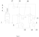
Figure 1 is a schematic flow diagram of a whole process continuous gas-assisted magnetic separation system provided by the present disclosure; -
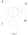
Figure 2 is a main view at the magnetic roller of a whole process continuous gas-assisted magnetic separation system provided by the present disclosure. - In the Figures:
1. adsorption tank; 2. extraction column; 3. desorber; 4. feed liquid inlet; 5. magnetic particle inlet; 6. stirring device; 7. air flotation column; 8. magnetic roller; 9. scraper; 10. mixture storage tank; 11. magnetic particle storage tank; 12. raffinate storage tank; 13. product storage tank; 14. peristaltic pump; 15. gas flowmeter; 16. magnetic arc region; 17. washing liquor storage tank. - The technical solution of the present disclosure will be further described below by way of specific embodiments in combination with accompanying drawings.
- As shown in
Figure 1 andFigure 2 , a whole process continuous gas-assisted magnetic separation system is provided by this example, the system comprises anadsorption tank 1, theadsorption tank 1 is connected with anextraction column 2, and theextraction column 2 is connected with adesorber 3; - a feed
liquid inlet 4 and a magnetic particle inlet 5 are arranged at the top of theadsorption tank 1, a mixed liquid outlet is arranged at the bottom of theadsorption tank 1, and astirring device 6 is arranged inside theadsorption tank 1; - the
extraction column 2 comprises a hollowair flotation column 7, a mixed liquid inlet and a raffinate outlet are arranged on theair flotation column 7, the mixed liquid inlet is connected with the mixed liquid outlet, and amagnetic roller 8 is arranged at the top of theair flotation column 7, ascraper 9 is arranged on one side of themagnetic roller 8, amixture storage tank 10 is arranged at the end of thescraper 9, and a gas inlet is arranged at the bottom of theair flotation column 7; - the
desorber 3 comprises a hollowair flotation column 7, a magnetic particle inlet and a product outlet are arranged on theair flotation column 7, and the magnetic particle inlet is connected with themixture storage tank 10, amagnetic roller 8 is arranged at the top of theair flotation column 7, ascraper 9 is arranged on one side of themagnetic roller 8, a magneticparticle storage tank 11 is arranged at the end of thescraper 9, the magneticparticle storage tank 11 is connected with the adsorption tank, and a gas inlet is arranged at the bottom of theair flotation column 7; - the
air flotation columns 7 of theextraction column 2 and thedesorber 3 are connected with a washing device, and the washing port of the washing device is arranged opposite to thescraper 9. - The
adsorption tank 1 in the system has a larger capacity, that is, it can be used to prepare a sufficient amount of adsorbed raw material liquid at one time for subsequent continuous use, and also provides high-capacity storage to easily realize the closed-loop circulation. A glass-made manhole and liquid level observation hole are arranged on theadsorption tank 1 so as to observe the materials and the liquid level in theadsorption tank 1. - The washing device comprises a washing
liquor storage tank 17 which is connected with the washing port, wherein theextraction column 2 and thedesorber 3 use the same washingliquor storage tank 17, or theextraction column 2 and thedesorber 3 are separately provided with a washingliquor storage tank 17. - In the whole process continuous gas-assisted magnetic separation system, a plurality of
extraction columns 2 and a plurality ofdesorbers 3 can be employed respectively, specifically a plurality ofextraction columns 2 are included, and the plurality ofextraction columns 2 are connected in series through mixed liquid inlets and raffinate outlets;
wherein, the mixed liquid inlet of theextraction column 2 at the head end is connected with the mixed liquid outlet, and the raffinate outlet of theextraction column 2 at the tail end is connected with theraffinate storage tank 12. - Alternatively, the whole process continuous gas-assisted magnetic separation system comprises a plurality of
extraction columns 2, the mixed liquid inlet of eachextraction column 2 is connected with the mixed liquid outlet, and the raffinate outlet of eachextraction column 2 is connected with theraffinate storage tank 12. - The above two forms are the plurality of
extraction columns 2 being connected in series and in parallel, respectively, wherein, when theextraction columns 2 are connected in series, they can be used for multi-stage magnetic separation, so that the magnetic particles in the raffinate can be separated more sufficiently; while when they are connected in parallel, a plurality ofextraction columns 2 can be used at the same time, resulting in higher magnetic separation efficiency. - Similarly, the
desorbers 3 can also be connected in series or in parallel, that is, a plurality ofdesorbers 3 can be included, and the plurality ofdesorbers 3 are connected in series through magnetic particle inlets and product outlets;
wherein, the magnetic particle inlet of thedesorber 3 at the head end is connected with themixture storage tank 10, and the product outlet of thedesorber 3 at the tail end is connected with theproduct storage tank 13. - Alternatively, the whole process continuous gas-assisted magnetic separation system comprises a plurality of
desorbers 3, the magnetic particle inlet of eachdesorber 3 is connected with themixture storage tank 10, and the product outlet of eachdesorber 3 is connected with theproduct storage tank 13. - The
desorbers 3 connected in series are more sufficient for the recovery of the magnetic particles and reduce the circulation loss of the magnetic particles; while thedesorbers 3 connected in parallel can improve the recovery efficiency of the magnetic particles. - The
feed liquid inlet 4, the magnetic particle inlet 5 and thestirring device 6 are arranged on the tank cover of theadsorption tank 1, and the tank cover of theadsorption tank 1 is connected with a lifting assembly. - The
adsorption tank 1 can be lifted and lowered by arranging a lifting assembly, which facilitates the maintenance and overhaul of the interior of the device in the later period, wherein, the lifting assembly is a telescopic cylinder, a hydraulic cylinder, and an electric hoist, etc. - Peristaltic pumps 14 are arranged between the
adsorption tank 1 and theextraction column 2, between theextraction column 2 and thedesorber 3 and between the washing device and thescraper 9, wherein, the flow rate of theperistaltic pump 14 is adjusted in a range of 3 to 6800 mL/min. - This example further comprises a control device which includes a controller, the controller is connected with the stirring
device 6, themagnetic roller 8, the lifting assembly and theperistaltic pump 14, and the controller is provided with a control button. The control device is arranged in the lower part of the system, which is easy to operate. The control device is provided with corresponding control buttons, which facilitates the unified manipulation of the operator. - This example further comprises a gas supply line which is connected with the gas inlets of the
extraction column 2 and thedesorber 3, respectively, andgas flowmeters 15 are arranged at the gas inlets of theextraction column 2 and thedesorber 3. - The
extraction column 2 and thedesorber 3 perform a unified gas supply operation through the gas supply line, wherein acorresponding gas flowmeter 15 is arranged at the gas inlet, and the measurement range of thegas flowmeter 15 is set at 6 to 60 L/h. - The
magnetic roller 8 comprises amagnetic arc region 16, and the arc of themagnetic arc region 16 is 240°. The surface of themagnetic arc region 16 of themagnetic roller 8 is made to have a relatively uniform capturing force on the magnetic particles. In the design of the magnetic circuit system, a certain amount of small-size rubidium ferroboron rare earth permanent magnets are arranged in an annular shape at a certain distance along the surface of a sleeve, so that a uniform magnetic field intensity on the surface of the sleeve can be generated. - The
mixture storage tank 10, the magneticparticle storage tank 11, theraffinate storage tank 12, theproduct storage tank 13, and the washingliquor storage tank 17 used in the whole process continuous gas-assisted magnetic separation system are all made of stainless steel, the shape of which is generally set to be a cuboid shape. At the same time, multiple spare storage tanks can be provided to configure and store the washing clear liquid and the desorption liquid. - Specifically, when in use, the magnetic carriers (i.e., magnetic particles) and the solution containing the target isolates are mixed in the
adsorption tank 1 and fully stirred by the stirringdevice 6 to accelerate the extraction process of the targets by the magnetic particles and promote the full suspension of the magnetic particles, then the mixture is pumped into the extraction column 2 (taking twoextraction columns 2 as an example, only one of them can be used, or they can be used simultaneously or alternately or in series), and the magnetic particles are fully captured by themagnetic roller 8 with the aid of theair flotation column 7. The magnetic particles on themagnetic roller 8 are washed off by the washing liquor pumped from the washingliquor storage tank 17 and collected into themixture storage tank 10, and the raffinate is collected into theraffinate storage tank 12, the suspension inside themixture storage tank 10 is pumped into thedesorber 3, and desorption liquid is contained in thedesorber 3, the targets desorb from the magnetic particles and enter theproduct storage tank 13, the desorbed magnetic particles are captured by themagnetic roller 8 and washed off by the washing liquor, and then enter the magneticparticle storage tank 11, the magnetic particles can be returned to the adsorption tank for recycling, and form a continuous closed-loop circulation.
Claims (7)
- A whole process continuous gas-assisted magnetic separation system, wherein it comprises an adsorption tank (1), the adsorption tank (1) is connected with an extraction column (2), and the extraction column (2) is connected with a desorber (3);the extraction column (2) comprises a hollow air flotation column (7), a mixed liquid inlet and a raffinate outlet are arranged on the air flotation column (7), the mixed liquid inlet is connected with a mixed liquid outlet, and a gas inlet is arranged at the bottom of the air flotation column (7);the desorber (3) comprises a hollow air flotation column (7), a magnetic particle inlet and a product outlet are arranged on the air flotation column (7), and the magnetic particle inlet is connected with a mixture storage tank (10), a magnetic roller (8) is arranged at the top of the air flotation column (7), a scraper (9) is arranged on one side of the magnetic roller (8), a magnetic particle storage tank (11) is arranged at the end of the scraper (9), the magnetic particle storage tank (11) is connected with the adsorption tank (1), and a gas inlet is arranged at the bottom of the air flotation column (7);characterized in thata feed liquid inlet (4) and a magnetic particle inlet (5) are arranged at the top of the adsorption tank (1), a mixed liquid outlet is arranged at the bottom of the adsorption tank (1), and a stirring device (6) is arranged inside the adsorption tank (1),wherein in the hollow air flotation column (7) of the extraction column (2), a magnetic roller (8) is arranged at the top of the air flotation column (7), a scraper (9) is arranged on one side of the magnetic roller (8), a mixture storage tank (10) is arranged at the end of the scraper (9),wherein the air flotation columns (7) of the extraction column (2) and the desorber (3) are connected with a washing device, and the washing port of the washing device is arranged opposite to the scraper (9),wherein peristaltic pumps (14) are arranged between the adsorption tank (1) and the extraction column (2), between the extraction column (2) and the desorber (3) and between the washing device and the scraper (9), wherein the flow rate of the peristaltic pump (14) is adjusted in a range of 3 to 6800 mL/min,wherein a gas supply line is connected with the gas inlets of the extraction column (2) and the desorber (3), respectively,wherein gas flowmeters (15) are arranged at the gas inlets of the extraction column (2) and the desorber (3), wherein the measurement range of the gas flowmeter (15) is set at 6 to 60 L/h; andwherein the magnetic rollers (8) of the extraction column (2) and the desorber (3) comprise a magnetic arc region (16), and the arc of the magnetic arc region (16) is 240°, and a certain amount of small-size rubidium ferroboron rare earth permanent magnets are arranged in an annular shape at a certain distance along the surface of the magnetic rollers (8).
- The whole process continuous gas-assisted magnetic separation system according to claim 1, wherein it comprises a plurality of extraction columns (2), and the plurality of the extraction columns (2) are connected in series through mixed liquid inlets and raffinate outlets;
wherein, the mixed liquid inlet of the extraction column (2) at the head end is connected with the mixed liquid outlet, and the raffinate outlet of the extraction column (2) at the tail end is connected with a raffinate storage tank (12). - The whole process continuous gas-assisted magnetic separation system according to claim 1, wherein it comprises a plurality of extraction columns (2), and the mixed liquid inlet of each extraction column (2) is connected with the mixed liquid outlet, and the raffinate outlet of each extraction column (2) is connected with a raffinate storage tank (12).
- The whole process continuous gas-assisted magnetic separation system according to any of claims 1 to 3, wherein it comprises a plurality of desorbers (3), and the plurality of the desorbers (3) are connected in series through magnetic particle inlets and product outlets;
wherein, the magnetic particle inlet of the desorber (3) at the head end is connected with the mixture storage tank (10), and the product outlet of the desorber (3) at the tail end is connected with the product storage tank (13). - The whole process continuous gas-assisted magnetic separation system according to claims 1-3,
wherein it comprises a plurality of desorbers (3),
and the magnetic particle inlet of each desorber (3) is connected with the mixture storage tank (10), and the product outlet of each desorber (3) is connected with the product storage tank (13). - The whole process continuous gas-assisted magnetic separation system according to any of claims 1 to 5, wherein the feed liquid inlet (4), the magnetic particle inlet (5) and the stirring device (6) are arranged on the tank cover of the adsorption tank (1), and the tank cover of the adsorption tank (1) is connected with a lifting assembly.
- The whole process continuous gas-assisted magnetic separation system according to claim 1, wherein it further comprises a control device which includes a controller, the controller is connected with the stirring device (6), the magnetic rollers (8) of the extraction column (2) and the desorber (3), the lifting assembly and the peristaltic pump (14), and the controller is provided with a control button.
Applications Claiming Priority (2)
| Application Number | Priority Date | Filing Date | Title |
|---|---|---|---|
| CN201710024548.3A CN106694224B (en) | 2017-01-11 | 2017-01-11 | A kind of whole process serialization gas magnetic assist separation system |
| PCT/CN2017/074332 WO2018129789A1 (en) | 2017-01-11 | 2017-02-22 | Whole-process continuous gas-assisted magnetic separation system |
Publications (4)
| Publication Number | Publication Date |
|---|---|
| EP3424600A1 EP3424600A1 (en) | 2019-01-09 |
| EP3424600A4 EP3424600A4 (en) | 2019-11-27 |
| EP3424600C0 EP3424600C0 (en) | 2024-08-14 |
| EP3424600B1 true EP3424600B1 (en) | 2024-08-14 |
Family
ID=58907469
Family Applications (1)
| Application Number | Title | Priority Date | Filing Date |
|---|---|---|---|
| EP17891394.3A Active EP3424600B1 (en) | 2017-01-11 | 2017-02-22 | Whole-process continuous gas-assisted magnetic separation system |
Country Status (3)
| Country | Link |
|---|---|
| EP (1) | EP3424600B1 (en) |
| CN (1) | CN106694224B (en) |
| WO (1) | WO2018129789A1 (en) |
Families Citing this family (2)
| Publication number | Priority date | Publication date | Assignee | Title |
|---|---|---|---|---|
| CN114870980A (en) * | 2022-06-07 | 2022-08-09 | 徐州工程学院 | Construction waste classifying, crushing, screening, sorting and recycling equipment |
| CN115569623B (en) * | 2022-09-29 | 2025-02-11 | 安徽松羽生物系统工程有限公司 | A highly efficient and continuous magnetic bead mother solution preparation device |
Family Cites Families (12)
| Publication number | Priority date | Publication date | Assignee | Title |
|---|---|---|---|---|
| WO1999032229A1 (en) * | 1997-12-22 | 1999-07-01 | Barry Graham Lumsden | Device and method for improving flotation process using magnetic fields |
| JP4353466B2 (en) * | 2003-09-02 | 2009-10-28 | 月島機械株式会社 | Adsorbent continuous supply / discharge type high gradient magnetic separator |
| WO2006049149A1 (en) * | 2004-11-05 | 2006-05-11 | Hitachi, Ltd. | Method and apparatus for removing organic substance from oily water from oilfield |
| CN100542677C (en) * | 2006-10-16 | 2009-09-23 | 中国科学院过程工程研究所 | Continuous production equipment for magnetic adsorption and desorption of biochemical products |
| CN200970548Y (en) * | 2006-11-16 | 2007-11-07 | 王美华 | Wet permanent magnet roller magnetic separator |
| CN201399375Y (en) * | 2009-04-09 | 2010-02-10 | 天地科技股份有限公司唐山分公司 | Magnetic separator capable of dewatering effectively |
| CN102133555A (en) * | 2010-01-26 | 2011-07-27 | 中国科学院过程工程研究所 | In-situ continuous separating device for magnetic medium particles |
| CN102500460B (en) * | 2011-09-26 | 2014-04-30 | 中国科学院过程工程研究所 | Air-assist superparamagnetic extraction method |
| EP2676733A1 (en) * | 2012-06-19 | 2013-12-25 | Siemens Aktiengesellschaft | Device for separating magnetic and/or magnetisable particles from a suspension and use of same |
| CN103159368B (en) * | 2013-04-15 | 2014-06-18 | 武汉钢铁(集团)公司 | Stage treatment type magnetic filter device |
| CN204017444U (en) * | 2014-07-21 | 2014-12-17 | 宁波市疾病预防控制中心 | A kind of efficient magnetic control disperses solid-phase extraction device |
| CN105301265B (en) * | 2015-10-10 | 2017-06-30 | 山西师范大学 | On-line automaticization Magnetic solid phases micro-extraction desorbs detection means and its method |
-
2017
- 2017-01-11 CN CN201710024548.3A patent/CN106694224B/en active Active
- 2017-02-22 WO PCT/CN2017/074332 patent/WO2018129789A1/en not_active Ceased
- 2017-02-22 EP EP17891394.3A patent/EP3424600B1/en active Active
Also Published As
| Publication number | Publication date |
|---|---|
| CN106694224A (en) | 2017-05-24 |
| EP3424600A1 (en) | 2019-01-09 |
| WO2018129789A1 (en) | 2018-07-19 |
| EP3424600A4 (en) | 2019-11-27 |
| EP3424600C0 (en) | 2024-08-14 |
| CN106694224B (en) | 2019-04-05 |
Similar Documents
| Publication | Publication Date | Title |
|---|---|---|
| CN203076080U (en) | Magnetic floatation separation device with jet bubble generators | |
| CN102992433B (en) | Extraction recovery method of waste water produced by naphthalene-series dye intermediate | |
| CN202638582U (en) | Magnetic flotation column | |
| CN105214339B (en) | Novel magnetic solid phase extracting device | |
| US20170276576A1 (en) | Portable efficient magnetic solid phase extraction device and extraction method thereof | |
| CN105087965A (en) | Method for extractive separation of La-Nd light rare earth | |
| EP3424600A1 (en) | Whole-process continuous gas-assisted magnetic separation system | |
| US11103865B2 (en) | Fixed bed counter-current regeneration device of ion exchange resin and application method of fixed bed counter-current regeneration device | |
| CN204607690U (en) | Activated sludge reaction and equipment for separating liquid from solid | |
| CN103286002B (en) | Permanent-magnetic spiral elutriation machine | |
| CN104726709A (en) | Process method for pre-separation three-outlet extraction separation of light rare earth ore | |
| CN205386493U (en) | Lithium cell anode material screening plant removes magnetic structure | |
| CN203076079U (en) | Magnetic floatation separation device with microbubble generators | |
| CN102500460B (en) | Air-assist superparamagnetic extraction method | |
| CN203304066U (en) | Permanent-magnet spiral washing machine | |
| CN201632096U (en) | Gravity Settling Concentrator for Quick Separation of Water and Soil in Slurry | |
| CN102794229B (en) | Vertical stirring concentrator | |
| CN202700661U (en) | Defoaming system for bauxite mineral separation | |
| CN100542677C (en) | Continuous production equipment for magnetic adsorption and desorption of biochemical products | |
| CN101823020B (en) | Permanent magnet vibration module type magnetic separator | |
| CN205199041U (en) | Novel magnetism solid -phase extraction device | |
| CN106957969B (en) | A kind of method of separation of rare earth elements | |
| CN206460006U (en) | A kind of online cleaning pump of liquid chromatograph | |
| CN205128175U (en) | Series connection permanent magnetism cylinder magnetic separation device | |
| CN114949926A (en) | Extraction separation system and bipyramid separator |
Legal Events
| Date | Code | Title | Description |
|---|---|---|---|
| STAA | Information on the status of an ep patent application or granted ep patent |
Free format text: STATUS: THE INTERNATIONAL PUBLICATION HAS BEEN MADE |
|
| PUAI | Public reference made under article 153(3) epc to a published international application that has entered the european phase |
Free format text: ORIGINAL CODE: 0009012 |
|
| STAA | Information on the status of an ep patent application or granted ep patent |
Free format text: STATUS: REQUEST FOR EXAMINATION WAS MADE |
|
| 17P | Request for examination filed |
Effective date: 20180827 |
|
| AK | Designated contracting states |
Kind code of ref document: A1 Designated state(s): AL AT BE BG CH CY CZ DE DK EE ES FI FR GB GR HR HU IE IS IT LI LT LU LV MC MK MT NL NO PL PT RO RS SE SI SK SM TR |
|
| AX | Request for extension of the european patent |
Extension state: BA ME |
|
| A4 | Supplementary search report drawn up and despatched |
Effective date: 20191030 |
|
| RIC1 | Information provided on ipc code assigned before grant |
Ipc: B03D 1/14 20060101ALI20191023BHEP Ipc: B03C 1/32 20060101AFI20191023BHEP Ipc: B03C 1/14 20060101ALI20191023BHEP Ipc: B03C 1/01 20060101ALI20191023BHEP Ipc: B03C 1/30 20060101ALI20191023BHEP Ipc: B03D 1/24 20060101ALI20191023BHEP Ipc: B03D 1/02 20060101ALI20191023BHEP |
|
| DAV | Request for validation of the european patent (deleted) | ||
| DAX | Request for extension of the european patent (deleted) | ||
| STAA | Information on the status of an ep patent application or granted ep patent |
Free format text: STATUS: EXAMINATION IS IN PROGRESS |
|
| 17Q | First examination report despatched |
Effective date: 20211222 |
|
| GRAP | Despatch of communication of intention to grant a patent |
Free format text: ORIGINAL CODE: EPIDOSNIGR1 |
|
| STAA | Information on the status of an ep patent application or granted ep patent |
Free format text: STATUS: GRANT OF PATENT IS INTENDED |
|
| RIC1 | Information provided on ipc code assigned before grant |
Ipc: B03D 1/24 20060101ALI20240222BHEP Ipc: B03D 1/14 20060101ALI20240222BHEP Ipc: B03D 1/02 20060101ALI20240222BHEP Ipc: B03C 1/01 20060101ALI20240222BHEP Ipc: B03C 1/30 20060101ALI20240222BHEP Ipc: B03C 1/14 20060101ALI20240222BHEP Ipc: B03C 1/32 20060101AFI20240222BHEP |
|
| INTG | Intention to grant announced |
Effective date: 20240312 |
|
| GRAS | Grant fee paid |
Free format text: ORIGINAL CODE: EPIDOSNIGR3 |
|
| GRAA | (expected) grant |
Free format text: ORIGINAL CODE: 0009210 |
|
| STAA | Information on the status of an ep patent application or granted ep patent |
Free format text: STATUS: THE PATENT HAS BEEN GRANTED |
|
| AK | Designated contracting states |
Kind code of ref document: B1 Designated state(s): AL AT BE BG CH CY CZ DE DK EE ES FI FR GB GR HR HU IE IS IT LI LT LU LV MC MK MT NL NO PL PT RO RS SE SI SK SM TR |
|
| REG | Reference to a national code |
Ref country code: GB Ref legal event code: FG4D |
|
| REG | Reference to a national code |
Ref country code: CH Ref legal event code: EP |
|
| REG | Reference to a national code |
Ref country code: DE Ref legal event code: R096 Ref document number: 602017084157 Country of ref document: DE |
|
| REG | Reference to a national code |
Ref country code: IE Ref legal event code: FG4D |
|
| U01 | Request for unitary effect filed |
Effective date: 20240909 |
|
| U07 | Unitary effect registered |
Designated state(s): AT BE BG DE DK EE FI FR IT LT LU LV MT NL PT RO SE SI Effective date: 20240925 |
|
| PG25 | Lapsed in a contracting state [announced via postgrant information from national office to epo] |
Ref country code: NO Free format text: LAPSE BECAUSE OF FAILURE TO SUBMIT A TRANSLATION OF THE DESCRIPTION OR TO PAY THE FEE WITHIN THE PRESCRIBED TIME-LIMIT Effective date: 20241114 |
|
| PG25 | Lapsed in a contracting state [announced via postgrant information from national office to epo] |
Ref country code: PL Free format text: LAPSE BECAUSE OF FAILURE TO SUBMIT A TRANSLATION OF THE DESCRIPTION OR TO PAY THE FEE WITHIN THE PRESCRIBED TIME-LIMIT Effective date: 20240814 Ref country code: GR Free format text: LAPSE BECAUSE OF FAILURE TO SUBMIT A TRANSLATION OF THE DESCRIPTION OR TO PAY THE FEE WITHIN THE PRESCRIBED TIME-LIMIT Effective date: 20241115 |
|
| PG25 | Lapsed in a contracting state [announced via postgrant information from national office to epo] |
Ref country code: IS Free format text: LAPSE BECAUSE OF FAILURE TO SUBMIT A TRANSLATION OF THE DESCRIPTION OR TO PAY THE FEE WITHIN THE PRESCRIBED TIME-LIMIT Effective date: 20241214 |
|
| PG25 | Lapsed in a contracting state [announced via postgrant information from national office to epo] |
Ref country code: HR Free format text: LAPSE BECAUSE OF FAILURE TO SUBMIT A TRANSLATION OF THE DESCRIPTION OR TO PAY THE FEE WITHIN THE PRESCRIBED TIME-LIMIT Effective date: 20240814 |
|
| PG25 | Lapsed in a contracting state [announced via postgrant information from national office to epo] |
Ref country code: RS Free format text: LAPSE BECAUSE OF FAILURE TO SUBMIT A TRANSLATION OF THE DESCRIPTION OR TO PAY THE FEE WITHIN THE PRESCRIBED TIME-LIMIT Effective date: 20241114 Ref country code: ES Free format text: LAPSE BECAUSE OF FAILURE TO SUBMIT A TRANSLATION OF THE DESCRIPTION OR TO PAY THE FEE WITHIN THE PRESCRIBED TIME-LIMIT Effective date: 20240814 |
|
| PG25 | Lapsed in a contracting state [announced via postgrant information from national office to epo] |
Ref country code: RS Free format text: LAPSE BECAUSE OF FAILURE TO SUBMIT A TRANSLATION OF THE DESCRIPTION OR TO PAY THE FEE WITHIN THE PRESCRIBED TIME-LIMIT Effective date: 20241114 Ref country code: PL Free format text: LAPSE BECAUSE OF FAILURE TO SUBMIT A TRANSLATION OF THE DESCRIPTION OR TO PAY THE FEE WITHIN THE PRESCRIBED TIME-LIMIT Effective date: 20240814 Ref country code: NO Free format text: LAPSE BECAUSE OF FAILURE TO SUBMIT A TRANSLATION OF THE DESCRIPTION OR TO PAY THE FEE WITHIN THE PRESCRIBED TIME-LIMIT Effective date: 20241114 Ref country code: IS Free format text: LAPSE BECAUSE OF FAILURE TO SUBMIT A TRANSLATION OF THE DESCRIPTION OR TO PAY THE FEE WITHIN THE PRESCRIBED TIME-LIMIT Effective date: 20241214 Ref country code: HR Free format text: LAPSE BECAUSE OF FAILURE TO SUBMIT A TRANSLATION OF THE DESCRIPTION OR TO PAY THE FEE WITHIN THE PRESCRIBED TIME-LIMIT Effective date: 20240814 Ref country code: GR Free format text: LAPSE BECAUSE OF FAILURE TO SUBMIT A TRANSLATION OF THE DESCRIPTION OR TO PAY THE FEE WITHIN THE PRESCRIBED TIME-LIMIT Effective date: 20241115 Ref country code: ES Free format text: LAPSE BECAUSE OF FAILURE TO SUBMIT A TRANSLATION OF THE DESCRIPTION OR TO PAY THE FEE WITHIN THE PRESCRIBED TIME-LIMIT Effective date: 20240814 |
|
| U20 | Renewal fee for the european patent with unitary effect paid |
Year of fee payment: 9 Effective date: 20250221 |
|
| PG25 | Lapsed in a contracting state [announced via postgrant information from national office to epo] |
Ref country code: SM Free format text: LAPSE BECAUSE OF FAILURE TO SUBMIT A TRANSLATION OF THE DESCRIPTION OR TO PAY THE FEE WITHIN THE PRESCRIBED TIME-LIMIT Effective date: 20240814 |
|
| PG25 | Lapsed in a contracting state [announced via postgrant information from national office to epo] |
Ref country code: CZ Free format text: LAPSE BECAUSE OF FAILURE TO SUBMIT A TRANSLATION OF THE DESCRIPTION OR TO PAY THE FEE WITHIN THE PRESCRIBED TIME-LIMIT Effective date: 20240814 |
|
| PG25 | Lapsed in a contracting state [announced via postgrant information from national office to epo] |
Ref country code: SK Free format text: LAPSE BECAUSE OF FAILURE TO SUBMIT A TRANSLATION OF THE DESCRIPTION OR TO PAY THE FEE WITHIN THE PRESCRIBED TIME-LIMIT Effective date: 20240814 |
|
| PGFP | Annual fee paid to national office [announced via postgrant information from national office to epo] |
Ref country code: GB Payment date: 20250220 Year of fee payment: 9 |
|
| PLBE | No opposition filed within time limit |
Free format text: ORIGINAL CODE: 0009261 |
|
| STAA | Information on the status of an ep patent application or granted ep patent |
Free format text: STATUS: NO OPPOSITION FILED WITHIN TIME LIMIT |
|
| 26N | No opposition filed |
Effective date: 20250515 |
|
| PG25 | Lapsed in a contracting state [announced via postgrant information from national office to epo] |
Ref country code: MC Free format text: LAPSE BECAUSE OF FAILURE TO SUBMIT A TRANSLATION OF THE DESCRIPTION OR TO PAY THE FEE WITHIN THE PRESCRIBED TIME-LIMIT Effective date: 20240814 |
|
| REG | Reference to a national code |
Ref country code: CH Ref legal event code: PL |
|
| PG25 | Lapsed in a contracting state [announced via postgrant information from national office to epo] |
Ref country code: CH Free format text: LAPSE BECAUSE OF NON-PAYMENT OF DUE FEES Effective date: 20250228 |
|
| PG25 | Lapsed in a contracting state [announced via postgrant information from national office to epo] |
Ref country code: IE Free format text: LAPSE BECAUSE OF NON-PAYMENT OF DUE FEES Effective date: 20250222 |