EP3424291A1 - Verteilgerät für streugut - Google Patents
Verteilgerät für streugut Download PDFInfo
- Publication number
- EP3424291A1 EP3424291A1 EP18401056.9A EP18401056A EP3424291A1 EP 3424291 A1 EP3424291 A1 EP 3424291A1 EP 18401056 A EP18401056 A EP 18401056A EP 3424291 A1 EP3424291 A1 EP 3424291A1
- Authority
- EP
- European Patent Office
- Prior art keywords
- drive shaft
- distributor
- fluid
- opening
- centrifugal disc
- Prior art date
- Legal status (The legal status is an assumption and is not a legal conclusion. Google has not performed a legal analysis and makes no representation as to the accuracy of the status listed.)
- Granted
Links
Images



Classifications
-
- A—HUMAN NECESSITIES
- A01—AGRICULTURE; FORESTRY; ANIMAL HUSBANDRY; HUNTING; TRAPPING; FISHING
- A01C—PLANTING; SOWING; FERTILISING
- A01C17/00—Fertilisers or seeders with centrifugal wheels
- A01C17/005—Driving mechanisms for the throwing devices
-
- A—HUMAN NECESSITIES
- A01—AGRICULTURE; FORESTRY; ANIMAL HUSBANDRY; HUNTING; TRAPPING; FISHING
- A01C—PLANTING; SOWING; FERTILISING
- A01C17/00—Fertilisers or seeders with centrifugal wheels
- A01C17/006—Regulating or dosing devices
- A01C17/008—Devices controlling the quantity or the distribution pattern
Definitions
- the invention relates to a distributor for spreading material according to the preamble of patent claim 1.
- Distributors for spreading material such as fertilizer spreaders usually have a drive shaft, by means of which a centrifugal disc is driven in rotation. On the centrifugal disc, one or more throwing blades can be arranged, which accelerate and eject the spreading material applied to the centrifugal disc.
- a corresponding distributor is for example in the document DE 39 35 104 A1 disclosed.
- Generic distribution devices usually have a pressure source, which is designed for example as a hydraulic connection, which is connectable to a hydraulic system of a tractor.
- a pressure source which is designed for example as a hydraulic connection, which is connectable to a hydraulic system of a tractor.
- a fertilizer spreader is known whose throwing blades are hydraulically adjustable.
- centrifugal discs have so far prevailed with adjusting devices which are actuated mechanically and / or electrically.
- Such mechanically and / or electrically actuatable adjusting devices regularly require a complex construction, whereby the manufacturing costs and the risk of a functional failure are increased.
- the known adjustment are functionally specific, so they can only be used to implement a function, such as the orientation of the throwing blades.
- the object on which the invention is based is thus to provide a distributor device which permits the arrangement of different adjustment devices to be actuated in the region of the centrifugal disk, without thereby the production costs or the risk of a functional failure are substantially increased.
- the object is achieved by a distributor of the aforementioned type, wherein the drive shaft has a recess extending between a first opening and a second opening recess and a fluid-conducting connection fluidly connects a pressure source via the first opening of the drive shaft with the recess of the drive shaft.
- the invention makes use of the finding that a pressurizable actuating fluid is provided by the fluid-conducting connection between the pressure source and the recess in the drive shaft in the drive shaft, which can be used to drive different adjustment and / or controlled operation of corresponding actuators .
- the pressurizable actuating fluid can be removed at the second opening of the drive shaft and used for actuating and / or controlling one or more device components.
- the recess of the drive shaft extends at least in sections in the axial direction through the drive shaft.
- the recess of the drive shaft extends at least in sections in the radial direction through the drive shaft.
- the recess of the drive shaft extends over the entire length of the drive shaft in the axial direction, so that the drive shaft is designed as a hollow shaft. If the drive shaft is designed as a hollow shaft, the first opening and the second opening, between which the recess of the drive shaft extends, are preferably arranged on the end faces of the drive shaft.
- Corresponding hollow shafts are comparatively inexpensive to produce and allow compliance with low manufacturing tolerances, so that the risk of functional impairment of the distributor, for example by an unintentional leakage in the drive shaft, is reduced.
- Extending over the entire length of the drive shaft The axial direction extending recess is preferably cylindrical, wherein the recess may have a constant over the entire length of the cross section or a plurality of regions, each having different cross sections.
- the first opening is arranged on an end face of the drive shaft or on a circumferential lateral surface of the drive shaft.
- the pressurizable actuating fluid is introduced into the recess of the drive shaft through the first opening. Since the fluid-conducting connection between the pressure source and the first opening of the drive shaft during operation of the distributor performs no rotational movement exists in the region of the first opening of the drive shaft, a transition region in which the actuating fluid is to be initiated by a non-rotating component in the rotating drive shaft. To this end, preferably adjoins the first recess of the drive shaft to a fluid chamber, which forms the transition region.
- the drive shaft extends in sections into the fluid chamber.
- the outer side of the drive shaft is preferably sealed off from the walls of the fluid chamber, in particular by means of a dynamic seal whose sealing effect is not impaired by differences in rotational speed of the surfaces to be sealed against each other.
- the second opening is arranged on an end face of the drive shaft or on a circumferential lateral surface of the drive shaft.
- the drive shaft extends through a recess in the centrifugal disc, so that the second opening is arranged above the centrifugal disc, when the second opening is arranged on an end face of the drive shaft.
- the second opening may be arranged above or below the centrifugal disk.
- the second opening may further comprise a connection device for connecting fluid-conducting components.
- the connection device may, for example, a thread for screwing a fluid-conducting component respectively.
- a fluid-conducting component can be pressed into the recess section adjoining the second opening.
- the distributor has a rotatably driven centrifugal disc, wherein the second opening of the drive shaft is arranged below or above the centrifugal disc.
- the centrifugal disc Above the centrifugal disc is preferably the task area on which the scattering material to be distributed is abandoned.
- the upper side of the centrifugal disk faces a metering device which meters the spreading material applied to the centrifugal disk.
- corresponding adjusting means or actuators which use the actuating fluid, can be arranged below or above the centrifugal disc.
- the second opening is arranged above the centrifugal disk, the access to the second opening and the fluid-conducting connected to the second opening components is simplified, so that the maintenance of these components can be performed without a costly disassembly. If the second opening is arranged below the centrifugal disk, it is avoided that an adjusting device or actuating device connected in a fluid-conducting manner with the second opening comes into contact with the spreading material fed onto the centrifugal disk. The risk of a functional impairment caused by the grit is thus reduced.
- an inventive distribution device is preferred in which the drive shaft is arranged in sections in a housing, wherein on the housing, a connection piece is fixed and the connection piece forms a part of the fluid-conducting connection.
- the housing comprises the fluid chamber, which adjoins the first opening of the drive shaft.
- the housing can support the drive shaft radially and / or axially, wherein between the housing and the drive shaft, a radial bearing and / or a thrust bearing can be arranged.
- the distribution device may comprise a fixed receiving element, which is adapted to support the drive shaft, wherein the receiving element is fixed to the housing and forms a part of the fluid-conducting connection.
- the receiving element can support the drive shaft radially and / or axially, wherein between the receiving element and the drive shaft, a radial bearing and / or a thrust bearing can be arranged.
- the receiving element may be connected to a connecting piece.
- a line, in particular a hose, can connect the connecting piece in a fluid-conducting manner with the pressure source.
- the distributor device has an actuating member which is fluid-conductively connected to the second opening of the drive shaft and is adapted to carry out an actuating operation by means of the actuating fluid.
- the actuator and the second opening of the drive shaft are arranged on the same side, starting from the centrifugal disc.
- the actuator is preferably formed as a variable-length adjusting cylinder or comprises one or more variable-length adjusting cylinder.
- a particularly preferred embodiment of the distributor according to the invention comprises a return device, which is adapted to perform a reset operation when the actuating fluid is below a pressure limit.
- the restoring means for example, an actuator can be returned to the initial state after performing an operation by performing the returning operation in which the actuator was before the execution of the operation.
- the restoring device preferably has one or more return springs.
- return springs By the use of return springs, the need for an active restoring device, which is operated, for example pneumatically, hydraulically, electrically and / or mechanically, overcome, so that a simple and cost-effective implementation of the reset function takes place.
- the pressure limit can be set at which the restoring device performs the reset operation.
- the one or more return springs and the second opening of the drive shaft are arranged on the same side from the slinger.
- the one or more return springs and the actuator are arranged on the same side from the centrifugal disc.
- the actuator is attached to the centrifugal disc.
- the actuator By attaching the actuator to the slinger, the actuator always has the same rotational speed as the slinger and the drive shaft.
- the attachment of the actuator to the centrifugal disc allows a pre-assembly of the centrifugal disc, whereby the production of the distributor is accelerated and simplified.
- the actuator is designed as a hydraulic cylinder or as a pneumatic cylinder.
- the actuating fluid is preferably a liquid.
- the actuating fluid is preferably a gas or a gas mixture.
- the distribution device comprises one or more adjustable guide elements which are adapted to guide the spreading material applied to the centrifugal disk.
- the one or more guide elements are adjustable by means of the actuator.
- one or more fixed guide elements can also be arranged, in particular fastened, on the centrifugal disk.
- the one or more guide elements may be formed independently of their adjustability as throwing blades.
- the position, the orientation and / or the length of the one or more guide elements on the centrifugal disk are adjustable by means of the actuating member.
- the one or more guide elements are pivotable and / or tiltable by means of the actuating member.
- the one or more adjustable guide elements thus allow improved normal and border spreading.
- the length of the one or more guide elements can be changed by telescoping the one or more guide elements by means of the actuator.
- the pressure source is designed as a fluid connection, which is adapted to be fluid-conductively connected to a fluid system of a vehicle pulling or carrying the distributor.
- the vehicle pulling or carrying the distributor is, for example, a tractor.
- the fluid system of the vehicle pulling or carrying the distributor can be, for example, a pneumatic system or a hydraulic system.
- the pressure source may be adapted to pressurize even a liquid actuating fluid or a gaseous actuating fluid.
- a separate fluid connection to a vehicle pulling or carrying the distributor is thus not necessary.
- the liquid actuating fluid may be a hydraulic fluid.
- the gaseous actuating fluid may be a gas or a gas mixture.
- the distributor may also include a plurality of drive shafts and / or a plurality of centrifugal discs, which may be formed according to the embodiments described above.
- the drive shaft may also include one or more further openings fluidly connected to the recess, wherein the one or more openings may be formed corresponding to the second opening described above and / or may be connected to one or more other actuators.
- the described components of the distributor are components of a dispensing unit, wherein the distributor may have one or more, in particular two, dispensing units.
- Distributor 10 shown is designed as a fertilizer control and we carried by a designed as a tractor vehicle 100.
- the vehicle 100 has two front wheels 102a, 102b and two rear wheels 104a, 104b and includes a cab 106.
- the distribution device 10 comprises a storage container 12, which is adapted to stockpile spreading material, namely fertilizer.
- the interior of the reservoir 12 is covered by a container lid 14.
- the reservoir 12 is supported by a support frame 16, wherein on the support frame 16 and two metering 20a, 20b are arranged.
- the dosing member 20a is adapted to supply the dispensing unit 22a with a metered quantity of spreading material.
- the metering member 20b is adapted to supply the dispensing unit 22b with a metered quantity of spreading material.
- support frame 16 On the support frame 16 also four support wheels 18a-18d are fixed, by means of which the distribution device 10 can be moved after it from the Vehicle 100 was discontinued and all connections to the vehicle 100 were released.
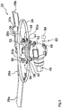
- the Fig. 2 shows a dispensing unit 22 of a fertilizer spreader designed as distribution device 10.
- the application units 22a, 22b of the in Fig. 1 illustrated distributor 10 may be formed according to this embodiment.
- the application unit 22 comprises a centrifugal disc 24 which is driven in rotation by a drive shaft 40.
- a centrifugal disc 24 On the centrifugal disc 24, two substantially opposite adjustable guide elements 26a, 26b are arranged, which are adapted to guide the on the centrifugal disc 24 abandoned pulp.
- the guide elements 26a, 26b are connected to one another via the connecting webs 32a, 32b. Further, on the slinger 24, a first pair of fixed guide members 28a, 28b and a second pair of fixed guide members 30a, 30b are arranged.
- the guide elements 26a, 26b can be moved from a first position shown to a second position on the centrifugal disk 24, wherein the guide elements 26a, 26b are in contact with the stop elements 34a, 34b in the second position.
- the guide elements 26a, 26b are in the first position, the spreading material fed onto the centrifugal disk 24 is guided by the guide elements 26a, 26b to the stationary guide elements 28a, 28b, which ultimately eject the spreading material. Due to the design and arrangement of the fixed guide elements 28a, 28b, a normal spreading is carried out in the first position of the guide elements 26a, 26b.
- the spreading material fed onto the centrifugal disk 24 is guided by the stationary guide elements 26a, 26b to the guide elements 30a, 30b, which ultimately eject the spreading material. Due to the design and arrangement of the fixed guide elements 30a, 30b, border spreading is carried out in the second position of the guide elements 26a, 26b. By means of a Return pin 38, the guide elements 26a, 26b from the second position back to the first position on the centrifugal disc 24 can be brought.
- the Fig. 3 shows that the drive shaft 40 is arranged in sections in a housing 42, wherein on the housing 42, a connecting piece 68 is attached.
- the connection piece 68 is a component of a fluid-conducting connection 82, which connects a pressure source 84 via a first opening 62 of the drive shaft 40 in a fluid-conducting manner with a recess 60 in the drive shaft 40.
- the pressure source 84 is formed as a fluid port configured to be fluidly connected to a fluid system of a vehicle 100 supporting the dispenser 10 such that the pressure source can provide a pressurizable actuating fluid.
- the actuating fluid is preferably a hydraulic fluid.
- an actuating member 48 designed as a hydraulic cylinder, which is connected in a fluid-conducting manner to the pressure source 84 via the fluid-conducting connection 52, the recess 60 in the drive shaft 40 and the fluid-conducting connection 82.
- the actuator 48 is configured to perform an actuating operation by means of the actuating fluid.
- the actuator 48 is supported on one side on a fixedly connected to the centrifugal disc 24 pin 50 a, so that a change in length of the actuator 48 causes a process of the actuating pin 36, by which the guide elements 26 a, 26 b are moved, so that the guide elements 26 a, 26 b 48 are adjustable by means of the actuator.
- a return device 54 is also arranged, which is adapted to perform a reset operation when the actuating fluid is below a pressure limit.
- the restoring device 54 has a return spring 56.
- the return device 54 is supported on one side on a fixedly connected to the centrifugal disc 24 pin 50 b, so that a change in length of the return device 54 causes a method of the return pin 38 through which the guide elements 26a, 26b are moved, so that the guide elements 26a, 26b are adjustable by means of the return device 54.
- the housing 42 On the side facing the centrifugal disc 24, the housing 42 is closed by means of a cover 44. Furthermore, an input shaft 46 is arranged in sections in the housing 42 and connected to transmit torque to the drive shaft 40.
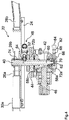
- the Fig. 4 shows that the input shaft 46 is connected via a bevel gear pair 58a, 58b to the drive shaft 60, wherein the pair of bevel gears 58a, 58b is disposed within the housing 42.
- the recess 60 of the drive shaft 40 extends between a first opening 62 and a second opening 64, wherein the recess 60 of the drive shaft 40 extends in an adjoining the first opening 62 region in the axial direction.
- a section of the recess 60 which extends in the radial direction through the drive shaft 40 adjoins the section of the recess 60 extending in the axial direction.
- the first opening 62 is arranged on an end face of the drive shaft 40, wherein the second opening 64 is arranged on a circumferential lateral surface of the drive shaft 40.
- the second opening 64 of the drive shaft 40 is disposed below the centrifugal disc 24.
- the actuator 48, the return spring 56 of the return device 54 and the second opening 64 of the drive shaft 40 are arranged on the same side starting from the centrifugal disc 24.
- a fixed receiving element 66 is arranged, which is adapted to support the drive shaft 40.
- a fluid chamber 70 is arranged, which is positioned immediately in front of the first recess 62 in the drive shaft 40.
- the receiving element 66 is connected to a connecting piece 68, wherein a hose formed as a hose, the connecting piece 68 fluid-conducting with the Pressure source 84 connects.
- the fluid chamber 70, the connecting piece 68 and the line formed as a hose are each components of the fluid-conducting connection 82, which connects the recess 60 of the drive shaft 40 with the pressure source 84.
- the receiving element 66 supports the drive shaft 40 via a radial bearing 72a.
- the distribution device 10 does not comprise a separate receiving element 66.
- the housing 42 preferably assumes all the functions of the non-present receiving element 66.
- the drive shaft 40 is connected via a shaft-hub connection 74 with the centrifugal disk 24.
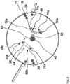
- the Fig. 5 shows that the slinger 24 has two slots 76a, 76b, wherein the actuating pin 36 extends through the slot 76a and the return pin 38 through the slot 76b.
- the actuator 48 is connected to the pin 50a via the hinged attachment 78a and to the actuation pin 36 via the hinged attachment 78b.
- the return device 54 is connected to the pin 50b via the articulated attachment 80a and to the return pin 38 via the articulated attachment 80b. With a change in length of the actuator 48 and the return device 54 of the actuating pin 36 is moved within the slot 76a and the return pin 38 within the slot 76b.
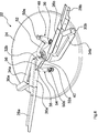
- the Fig. 6 shows an alternative embodiment of a dispensing unit 22 of a distributor 10, wherein the actuator 48 and the return means 54 are arranged above the centrifugal disc 24 and thus in the feed region of the centrifugal disc 24.
- the actuator 48 is again connected via a pin 50 a with the centrifugal disk 24, wherein an actuating pin 48 coupled to the actuating pin 36 is guided (concealed) within a slot and is adapted to move the guide elements 26a, 26b on the centrifugal disc 24.
- the restoring device 54 is again connected to the slinger 24 via a pin 50b, wherein a return pin 38 coupled to the restoring device 54 is guided within a slot (concealed) and is adapted to move the guide elements 26a, 26b on the slinger 24.
- guide elements 26a, 26b, 28a, 28b, 30a, 30b is consistent with the design and arrangement of the in the Fig. 2 to 5 shown guide elements 26a, 26b, 28a, 28b, 30a, 30b match.
- the Fig. 7 shows that the second opening 64 of the drive shaft is arranged in this embodiment at an end face of the drive shaft 40.
- the recess 60 extends over the entire length of the drive shaft 40, so that the drive shaft 40 is formed as a hollow shaft.
- the first opening 62 and the second opening 64 are arranged on opposite end faces of the drive shaft 40.
- the second opening 64 is arranged above the centrifugal disk 24, so that the fluid-conducting connection 52 designed as a hose is also arranged between the second opening 64 and the actuating member 48 above the centrifugal disk 24.
Landscapes
- Life Sciences & Earth Sciences (AREA)
- Soil Sciences (AREA)
- Environmental Sciences (AREA)
- Fertilizing (AREA)
Abstract
Description
- Die Erfindung betrifft ein Verteilgerät für Streugut nach dem Oberbegriff des Patentanspruchs 1.
- Verteilgeräte für Streugut, wie beispielsweise Düngerstreuer, weisen üblicherweise eine Antriebswelle auf, mittels welcher eine Schleuderscheibe rotierend angetrieben wird. Auf der Schleuderscheibe kann eine oder können mehrere Wurfschaufeln angeordnet sein, welche das auf die Schleuderscheibe aufgegebene Streugut beschleunigen und auswerfen.
- Zur Veränderung der Abwurfcharakteristik sind Verteilgeräte bekannt, bei welchen die Wurfschaufeln verstellbar sind. Ein entsprechendes Verteilgerät ist beispielsweise in der Druckschrift
DE 39 35 104 A1 offenbart. - Gattungsgemäße Verteilgeräte weisen üblicherweise eine Druckquelle auf, welche beispielsweise als Hydraulikanschluss ausgebildet ist, welcher mit einem Hydrauliksystem eines Traktors verbindbar ist. Aus der Druckschrift
DE 10 2007 021 442 B4 ist beispielsweise ein Düngerstreuer bekannt, dessen Wurfschaufeln hydraulisch verstellbar sind. - In der Praxis haben sich jedoch bisher Schleuderscheiben mit Verstelleinrichtungen durchgesetzt, welche mechanisch und/oder elektrisch betätigt werden. Derartige mechanisch und/oder elektrisch betätigbare Verstelleinrichtungen erfordern regelmäßig eine aufwändige Konstruktion, wodurch die Herstellungskosten und das Risiko eines Funktionsausfalls erhöht sind. Ferner sind die bekannten Verstelleinrichtungen funktionsspezifisch ausgebildet, sodass diese lediglich zur Umsetzung einer Funktion, beispielsweise der Ausrichtung der Wurfschaufeln, eingesetzt werden können.
- Die der Erfindung zugrunde liegende Aufgabe besteht somit darin, ein Verteilgerät bereitzustellen, welches die Anordnung unterschiedlicher zu betätigender Verstelleinrichtungen im Bereich der Schleuderscheibe erlaubt, ohne dass dabei die Herstellungskosten oder das Risiko eines Funktionsausfalls wesentlich gesteigert werden.
- Die Aufgabe wird gelöst durch ein Verteilgerät der eingangs genannten Art, wobei die Antriebswelle eine sich zwischen einer ersten Öffnung und einer zweiten Öffnung erstreckende Ausnehmung aufweist und eine fluidleitende Verbindung eine Druckquelle über die erste Öffnung der Antriebswelle fluidleitend mit der Ausnehmung der Antriebswelle verbindet.
- Die Erfindung macht sich die Erkenntnis zunutze, dass durch die fluidleitende Verbindung zwischen der Druckquelle und der Ausnehmung in der Antriebswelle im Bereich der Schleuderscheibe ein mit Druck beaufschlagbares Betätigungsfluid bereitgestellt wird, welches zum Antrieb unterschiedlicher Verstelleinrichtungen und/oder zum gesteuerten Betrieb entsprechender Betätigungseinrichtungen verwendet werden kann. Im Betrieb des Verteilgeräts kann also das mit Druck beaufschlagbare Betätigungsfluid an der zweiten Öffnung der Antriebswelle abgenommen und zum Betätigen und/oder Steuern von einer oder mehreren Gerätekomponenten verwendet werden.
- In einer bevorzugten Ausführungsform des erfindungsgemäßen Verteilgeräts erstreckt sich die Ausnehmung der Antriebswelle zumindest abschnittsweise in axialer Richtung durch die Antriebswelle. Alternativ oder zusätzlich erstreckt sich die Ausnehmung der Antriebswelle zumindest abschnittsweise in radialer Richtung durch die Antriebswelle. Beispielsweise erstreckt sich die Ausnehmung der Antriebswelle über die gesamte Länge der Antriebswelle in axialer Richtung, sodass die Antriebswelle als Hohlwelle ausgebildet ist. Wenn die Antriebswelle als Hohlwelle ausgebildet ist, sind die erste Öffnung und die zweite Öffnung, zwischen welchen sich die Ausnehmung der Antriebswelle erstreckt, vorzugsweise an den Stirnseiten der Antriebswelle angeordnet. Entsprechende Hohlwellen sind vergleichsweise kostengünstig herstellbar und erlauben die Einhaltung geringer Fertigungstoleranzen, sodass das Risiko einer Funktionsbeeinträchtigung des Verteilgeräts, beispielsweise durch eine unbeabsichtigte Leckage im Bereich der Antriebswelle, verringert ist. Die sich über die gesamte Länge der Antriebswelle in axialer Richtung erstreckende Ausnehmung ist vorzugsweise zylindrisch ausgebildet, wobei die Ausnehmung einen über die gesamte Länge konstanten Querschnitt oder mehrere Bereiche mit jeweils unterschiedlichen Querschnitten aufweisen kann.
- In einer anderen Ausführungsform des erfindungsgemäßen Verteilgeräts ist die erste Öffnung an einer Stirnseite der Antriebswelle oder auf einer umlaufenden Mantelfläche der Antriebswelle angeordnet. Durch die erste Öffnung wird im Betrieb des Verteilgeräts das mit Druck beaufschlagbare Betätigungsfluid in die Ausnehmung der Antriebswelle eingeleitet. Da die fluidleitende Verbindung zwischen der Druckquelle und der ersten Öffnung der Antriebswelle im Betrieb des Verteilgeräts keine Rotationsbewegung ausführt, existiert im Bereich der ersten Öffnung der Antriebswelle ein Übergangsbereich, in welchem das Betätigungsfluid von einer nicht-rotierenden Komponente in die rotierende Antriebswelle einzuleiten ist. Hierzu schließt sich an die erste Ausnehmung der Antriebswelle vorzugsweise eine Fluidkammer an, welche den Übergangsbereich ausbildet. Die Antriebswelle erstreckt sich abschnittsweise in die Fluidkammer hinein. Die Außenseite der Antriebswelle ist vorzugsweise gegenüber der Bewandung der Fluidkammer abgedichtet, insbesondere mittels einer dynamischen Dichtung, deren Dichtwirkung durch Drehzahldifferenzen der gegeneinander abzudichtenden Flächen nicht beeinträchtigt wird.
- In einer bevorzugten Weiterbildung des erfindungsgemäßen Verteilgeräts ist die zweite Öffnung an einer Stirnseite der Antriebswelle oder auf einer umlaufenden Mantelfläche der Antriebswelle angeordnet. Insbesondere erstreckt sich die Antriebswelle durch eine Ausnehmung in der Schleuderscheibe, sodass die zweite Öffnung oberhalb der Schleuderscheibe angeordnet ist, wenn die zweite Öffnung an einer Stirnseite der Antriebswelle angeordnet ist. Wenn die zweite Öffnung auf der umlaufenden Mantelfläche der Antriebswelle angeordnet ist, kann die zweite Öffnung oberhalb oder unterhalb der Schleuderscheibe angeordnet sein. Die zweite Öffnung kann ferner eine Anschlusseinrichtung zum Anschließen fluidleitender Komponenten umfassen. Die Anschlusseinrichtung kann beispielsweise ein Gewinde zum Eindrehen einer fluidleitenden Komponente aufweisen. Ferner kann im Bereich der zweiten Öffnung eine fluidleitende Komponente in den an die zweite Öffnung anschließenden Ausnehmungsabschnitt eingepresst sein.
- In einer besonders bevorzugten Ausführungsform weist das Verteilgerät eine rotierend antreibbare Schleuderscheibe auf, wobei die zweite Öffnung der Antriebswelle unterhalb oder oberhalb der Schleuderscheibe angeordnet ist. Oberhalb der Schleuderscheibe befindet sich vorzugsweise der Aufgabebereich, auf welchen das zu verteilende Streugut aufgegeben wird. Vorzugsweise ist die Oberseite der Schleuderscheibe einem Dosierorgan zugewandt, welches das auf die Schleuderscheibe aufgegebene Streugut dosiert. Dadurch, dass die zweite Öffnung der Antriebswelle unterhalb oder oberhalb der Schleuderscheibe angeordnet ist, können entsprechende Verstelleinrichtungen oder Betätigungseinrichtungen, welche das Betätigungsfluid nutzen, unterhalb oder oberhalb der Schleuderscheibe angeordnet sein. Wenn die zweite Öffnung oberhalb der Schleuderscheibe angeordnet ist, ist der Zugang zu der zweiten Öffnung und den mit der zweiten Öffnung fluidleitend verbundenen Komponenten vereinfacht, sodass die Wartung dieser Komponenten ohne eine aufwändige Demontage ausführbar ist. Wenn die zweite Öffnung unterhalb der Schleuderscheibe angeordnet ist, wird vermieden, dass eine mit der zweiten Öffnung fluidleitend verbundene Verstelleinrichtung oder Betätigungseinrichtung in Kontakt mit dem auf die Schleuderscheibe aufgegebenen Streugut kommt. Das Risiko einer durch das Streugut hervorgerufenen Funktionsbeeinträchtigung wird somit verringert.
- Außerdem ist ein erfindungsgemäßes Verteilgerät bevorzugt, bei welchem die Antriebswelle abschnittsweise in einem Gehäuse angeordnet ist, wobei an dem Gehäuse ein Anschlussstutzen befestigt ist und der Anschlussstutzen einen Teil der fluidleitenden Verbindung ausbildet. Vorzugsweise umfasst das Gehäuse die Fluidkammer, welche sich an die erste Öffnung der Antriebswelle anschließt. Das Gehäuse kann die Antriebswelle radial und/oder axial abstützen, wobei zwischen dem Gehäuse und der Antriebswelle ein Radiallager und/oder ein Axiallager angeordnet sein kann. Vorzugsweise ist zwischen der Außenseite der Antriebswelle und dem Gehäuse eine dynamische Dichtung angeordnet. Alternativ kann das Verteilgerät ein feststehendes Aufnahmeelement aufweisen, welches dazu eingerichtet ist, die Antriebswelle abzustützen, wobei das Aufnahmeelement an dem Gehäuse befestigt ist und ein Teil der fluidleitenden Verbindung ausbildet. Das Aufnahmeelement kann die Antriebswelle radial und/oder axial abstützen, wobei zwischen dem Aufnahmeelement und der Antriebswelle ein Radiallager und/oder ein Axiallager angeordnet sein kann. Das Aufnahmeelement kann mit einem Anschlussstutzen verbunden sein. Eine Leitung, insbesondere ein Schlauch, kann den Anschlussstutzen fluidleitend mit der Druckquelle verbinden.
- In einer weiteren vorteilhaften Ausführungsform weist das erfindungsgemäße Verteilgerät ein Betätigungsglied auf, welches fluidleitend mit der zweiten Öffnung der Antriebswelle verbunden und dazu eingerichtet ist, mittels des Betätigungsfluids einen Betätigungsvorgang auszuführen. Vorzugsweise sind das Betätigungsglied und die zweite Öffnung der Antriebswelle auf der gleichen Seite ausgehend von der Schleuderscheibe angeordnet. Somit besteht nicht die Notwendigkeit einer fluidleitenden Verbindung, welche das aus der zweiten Öffnung austretende Betätigungsfluid von einer Seite der Schleuderscheibe auf die andere Seite der Schleuderscheibe leitet. Das Betätigungsglied ist vorzugsweise als längenveränderlicher Einstellzylinder ausgebildet oder umfasst einen oder mehrere längenveränderliche Einstellzylinder.
- Eine besonders bevorzugte Ausführungsform des erfindungsgemäßen Verteilgeräts weist eine Rückstelleinrichtung auf, welche dazu eingerichtet ist, einen Rückstellvorgang auszuführen, wenn das Betätigungsfluid einen Druckgrenzwert unterschreitet. Durch die Rückstelleinrichtung kann beispielsweise ein Betätigungsglied nach Ausführen eines Betätigungsvorgangs durch das Ausführen des Rückstellvorgangs wieder in den ursprünglichen Zustand überführt werden, in welchem sich das Betätigungsglied vor der Ausführung des Betätigungsvorgangs befand. Vorzugsweise weist die Rückstelleinrichtung eine oder mehrere Rückstellfedern auf. Durch die Verwendung von Rückstellfedern wird die Notwendigkeit einer aktiven Rückstelleinrichtung, welche beispielsweise pneumatisch, hydraulisch, elektrisch und/oder mechanisch betrieben wird, überwunden, sodass eine einfache und kostengünstige Umsetzung der Rückstellfunktion erfolgt. Über die eine oder die mehreren Rückstellfedern kann der Druckgrenzwert eingestellt werden, bei welchem die Rückstelleinrichtung den Rückstellvorgang ausführt. Vorzugsweise ist die eine oder sind die mehreren Rückstellfedern und die zweite Öffnung der Antriebswelle auf der gleichen Seite ausgehend von der Schleuderscheibe angeordnet. Insbesondere ist die eine oder sind die mehreren Rückstellfedern und das Betätigungsglied auf der gleichen Seite ausgehend von der Schleuderscheibe angeordnet.
- In einer weiteren bevorzugten Ausführungsform des erfindungsgemäßen Verteilgeräts ist das Betätigungsglied an der Schleuderscheibe befestigt. Durch die Befestigung des Betätigungsglieds an der Schleuderscheibe weist das Betätigungsglied stets die gleiche Rotationsgeschwindigkeit wie die Schleuderscheibe und die Antriebswelle auf. Somit besteht nicht die Notwendigkeit, dass die fluidleitende Verbindung zwischen der zweiten Öffnung der Antriebswelle und dem Betätigungsglied Relativbewegungen des Betätigungsglieds und der Antriebswelle auszugleichen hat. Ferner erlaubt die Befestigung des Betätigungsglieds an der Schleuderscheibe eine Vormontage der Schleuderscheibe, wodurch die Herstellung des Verteilgeräts beschleunigt und vereinfacht wird.
- Bevorzugt ist außerdem ein erfindungsgemäßes Verteilgerät, bei welchem das Betätigungsglied als Hydraulikzylinder oder als Pneumatikzylinder ausgebildet ist. Wenn das Betätigungsglied als Hydraulikzylinder ausgebildet ist, ist das Betätigungsfluid vorzugsweise eine Flüssigkeit. Wenn das Betätigungsglied als Pneumatikzylinder ausgebildet ist, ist das Betätigungsfluid vorzugsweise ein Gas oder ein Gasgemisch.
- In einer anderen Ausführungsform weist das erfindungsgemäße Verteilgerät ein oder mehrere verstellbare Führungselemente auf, welche dazu eingerichtet sind, das auf die Schleuderscheibe aufgegebene Streugut zu führen. Das eine oder die mehreren Führungselemente sind dabei mittels des Betätigungsglieds verstellbar. Zusätzlich zu dem einen oder den mehreren verstellbaren Führungselementen können an der Schleuderscheibe auch ein oder mehrere feststehende Führungselemente angeordnet, insbesondere befestigt sein. Das eine oder die mehreren Führungselemente können unabhängig von ihrer Verstellbarkeit als Wurfschaufeln ausgebildet sein.
- In einer weiteren bevorzugten Ausführungsform des erfindungsgemäßen Verteilgeräts sind die Position, die Ausrichtung und/oder die Länge des einen oder der mehreren Führungselemente auf der Schleuderscheibe mittels des Betätigungsglieds verstellbar. Vorzugsweise ist das eine oder sind die mehreren Führungselemente mittels des Betätigungsglieds verschwenkbar und/oder verkippbar. Durch die Verstellung der Position, der Ausrichtung und/oder der Länge des einen oder der mehreren Führungselemente auf der Schleuderscheibe können unterschiedliche Abwurfcharakteristiken und somit unterschiedliche Streubilder eingestellt werden. Das eine oder die mehreren verstellbaren Führungselemente erlauben somit ein verbessertes Normal- und Grenzstreuen. Insbesondere kann die Länge des einen oder der mehreren Führungselemente über ein Teleskopieren des einen oder der mehreren Führungselemente mittels des Betätigungsglieds verändert werden.
- In einer anderen Ausführungsform des erfindungsgemäßen Verteilgeräts ist die Druckquelle als Fluidanschluss ausgebildet, welcher dazu eingerichtet ist, mit einem Fluidsystem eines das Verteilgerät ziehenden oder tragenden Fahrzeugs fluidleitend verbunden zu werden. Das das Verteilgerät ziehende oder tragende Fahrzeug ist beispielsweise ein Traktor. Das Fluidsystem des das Verteilgerät ziehenden oder tragenden Fahrzeugs kann beispielsweise ein Pneumatiksystem oder ein Hydrauliksystem sein. Dadurch, dass die Druckquelle als Fluidanschluss ausgebildet ist, welcher dazu eingerichtet ist, mit dem Fluidsystem eines das Verteilgerät ziehenden oder tragenden Fahrzeugs fluidleitend verbunden zu werden, kann der an der zweiten Öffnung der Antriebswelle abnehmbare Druck des Betätigungsfluids direkt aus dem Fahrzeug gesteuert werden, sodass auch das Betätigungsglied direkt aus dem Fahrzeug steuerbar ist.
- Alternativ kann die Druckquelle dazu eingerichtet sein, selbst ein flüssiges Betätigungsfluid oder ein gasförmiges Betätigungsfluid mit Druck zu beaufschlagen. Eine separate Fluidverbindung zu einem das Verteilgerät ziehenden oder tragenden Fahrzeugs ist somit nicht notwendig. Das flüssige Betätigungsfluid kann eine Hydraulikflüssigkeit sein. Das gasförmige Betätigungsfluid kann ein Gas oder ein Gasgemisch sein.
- Das Verteilgerät kann außerdem mehrere Antriebswellen und/oder mehrere Schleuderscheiben aufweisen, welche entsprechend der vorstehend beschriebenen Ausführungsformen ausgebildet sein können.
- Die Antriebswelle kann außerdem eine oder mehrere weitere Öffnungen aufweisen, welche fluidleitend mit der Ausnehmung verbunden sind, wobei die eine oder die mehreren Öffnungen entsprechend der vorstehend beschriebenen zweiten Öffnung ausgebildet sein können und/oder mit einer oder mehreren weiteren Betätigungsgliedern verbunden sein können. Vorzugsweise sind die beschriebenen Komponenten des Verteilgeräts Bestandteile einer Ausbringeinheit, wobei das Verteilgerät eine oder mehrere, insbesondere zwei, Ausbringeinheiten aufweisen kann.
- Weitere Einzelheiten der Erfindung sind der Figurenbeschreibung und den Zeichnungen zu entnehmen. Es zeigen
- Fig. 1
- ein Ausführungsbeispiel des erfindungsgemäßen Verteilgeräts in einer perspektivischen Darstellung;
- Fig. 2
- eine Ausbringeinheit eines erfindungsgemäßen Verteilgeräts in einer perspektivischen Darstellung;
- Fig. 3
- die in der
Fig. 2 dargestellte Ausbringeinheit in einer weiteren perspektivischen Darstellung; - Fig. 4
- die in der
Fig. 2 dargestellte Ausbringeinheit in einer Schnittdarstellung; - Fig. 5
- die in der
Fig. 2 dargestellte Ausbringeinheit in einer Darstellung von unten; - Fig. 6
- eine weitere Ausbringeinheit eines erfindungsgemäßen Verteilgeräts in einer perspektivischen Darstellung; und
- Fig. 7
- die in der
Fig. 6 dargestellte Ausbringeinheit in einer Schnittdarstellung. - Das in der
Fig. 1 dargestellte Verteilgerät 10 ist als Düngersteuer ausgebildet und wir von einem als Traktor ausgebildeten Fahrzeug 100 getragen. - Das Fahrzeug 100 weist zwei Vorderräder 102a, 102b und zwei Hinterräder 104a, 104b auf und umfasst ein Führerhaus 106.
- Das Verteilgerät 10 umfasst einen Vorratsbehälter 12, welche dazu eingerichtet ist, Streugut, nämlich Dünger, zu bevorraten. Der Innenraum des Vorratsbehälters 12 wird von einem Behälterdeckel 14 abgedeckt. Der Vorratsbehälter 12 wird von einem Tragrahmen 16 getragen, wobei an dem Tragrahmen 16 auch zwei Dosierorgane 20a, 20b angeordnet sind. Das Dosierorgan 20a ist dazu eingerichtet, der Ausbringeinheit 22a eine dosierte Menge an Streugut zuzuführen. Das Dosierorgan 20b ist dazu eingerichtet, der Ausbringeinheit 22b eine dosierte Menge an Streugut zuzuführen. Beim Zuführen des Streuguts wird die dosierte Menge des den Vorratsbehälter 12 verlassenden Streuguts jeweils auf eine Schleuderscheibe 24a, 24b der Ausbringeinheiten 22a, 22b aufgegeben. Die Schleuderscheiben 24a, 24b der Ausbringeinheiten 22a, 22b beschleunigen das Streugut und werfen das Streugut aus.
- An dem Tragrahmen 16 sind außerdem vier Stützräder 18a-18d befestigt, mittels welchen das Verteilgerät 10 verfahren werden kann, nachdem es von dem Fahrzeug 100 abgesetzt wurde und sämtliche Verbindungen zu dem Fahrzeug 100 gelöst wurden.
- Die
Fig. 2 zeigt eine Ausbringeinheit 22 eines als Düngerstreuer ausgebildeten Verteilgeräts 10. Beispielsweise können die Ausbringeinheiten 22a, 22b des in derFig. 1 dargestellten Verteilgeräts 10 gemäß dieser Ausführung ausgebildet sein. - Die Ausbringeinheit 22 umfasst eine Schleuderscheibe 24, welche von einer Antriebswelle 40 rotierend angetrieben wird. Auf der Schleuderscheibe 24 sind zwei im Wesentlichen gegenüberliegende verstellbare Führungselemente 26a, 26b angeordnet, welche dazu eingerichtet sind, das auf die Schleuderscheibe 24 aufgegebene Streugut zu führen. Die Führungselemente 26a, 26b sind über die Verbindungsstege 32a, 32b miteinander verbunden. Ferner sind auf der Schleuderscheibe 24 ein erstes Paar von feststehenden Führungselementen 28a, 28b und ein zweites Paar von feststehenden Führungselementen 30a, 30b angeordnet.
- Mittels eines Betätigungsstifts 36 sind die Führungselemente 26a, 26b von einer ersten dargestellten Position in eine zweite Position auf der Schleuderscheibe 24 verbringbar, wobei die Führungselemente 26a, 26b in der zweiten Position in Kontakt mit den Anschlagselementen 34a, 34b stehen. Wenn sich die Führungselemente 26a, 26b in der ersten Position befinden, wird das auf die Schleuderscheibe 24 aufgegebene Streugut durch die Führungselemente 26a, 26b zu den feststehenden Führungselementen 28a, 28b geleitet, welche das Streugut letztendlich auswerfen. Durch die Ausbildung und Anordnung der feststehenden Führungselemente 28a, 28b wird in der ersten Position der Führungselemente 26a, 26b ein Normalstreuen ausgeführt. Wenn sich die Führungselemente 26a, 26b in der zweiten Position befinden, wird das auf die Schleuderscheibe 24 aufgegebene Streugut durch die feststehenden Führungselemente 26a, 26b zu den Führungselementen 30a, 30b geleitet, welche das Streugut letztendlich auswerfen. Durch die Ausbildung und Anordnung der feststehenden Führungselemente 30a, 30b wird in der zweiten Position der Führungselemente 26a, 26b ein Grenzstreuen ausgeführt. Mittels eines Rückstellstifts 38 sind die Führungselemente 26a, 26b von der zweiten Position wieder in die erste Position auf der Schleuderscheibe 24 verbringbar.
- Die
Fig. 3 zeigt, dass die Antriebswelle 40 abschnittsweise in einem Gehäuse 42 angeordnet ist, wobei an dem Gehäuse 42 ein Anschlussstutzen 68 befestigt ist. Der Anschlussstutzen 68 ist ein Bestandteil einer fluidleitenden Verbindung 82, welche eine Druckquelle 84 über eine erste Öffnung 62 der Antriebswelle 40 fluidleitend mit einer Ausnehmung 60 in der Antriebswelle 40 verbindet. Die Druckquelle 84 ist als Fluidanschluss ausgebildet, welcher dazu eingerichtet ist, mit einem Fluidsystem eines das Verteilgerät 10 tragenden Fahrzeugs 100 fluidleitend verbunden zu werden, sodass die Druckquelle ein mit Druck beaufschlagbares Betätigungsfluid bereitzustellen kann. Das Betätigungsfluid ist vorzugsweise eine Hydraulikflüssigkeit. - Unterhalb der Schleuderscheibe 24 ist ein als Hydraulikzylinder ausgebildetes Betätigungsglied 48 angeordnet, welches über die als Schlauch ausgebildete fluidleitende Verbindung 52, die Ausnehmung 60 in der Antriebswelle 40 und die fluidleitende Verbindung 82 fluidleitend mit der Druckquelle 84 verbunden ist. Das Betätigungsglied 48 ist dazu eingerichtet, mittels des Betätigungsfluids einen Betätigungsvorgang auszuführen. Hierfür stützt sich das Betätigungsglied 48 an einer Seite an einem fest mit der Schleuderscheibe 24 verbundenen Stift 50a ab, sodass eine Längenveränderung des Betätigungsglieds 48 ein Verfahren des Betätigungsstifts 36 verursacht, durch welchen die Führungselemente 26a, 26b bewegt werden, sodass die Führungselemente 26a, 26b mittels des Betätigungsglieds 48 verstellbar sind.
- Unterhalb der Schleuderscheibe 24 ist außerdem eine Rückstelleinrichtung 54 angeordnet, welche dazu eingerichtet ist, einen Rückstellvorgang auszuführen, wenn das Betätigungsfluid einen Druckgrenzwert unterschreitet. Die Rückstelleinrichtung 54 weist eine Rückstellfeder 56 auf. Die Rückstelleinrichtung 54 stützt sich an einer Seite an einem fest mit der Schleuderscheibe 24 verbundenen Stift 50b ab, sodass eine Längenveränderung der Rückstelleinrichtung 54 ein Verfahren des Rückstellstifts 38 verursacht, durch welchen die Führungselemente 26a, 26b bewegt werden, sodass die Führungselemente 26a, 26b mittels der Rückstelleinrichtung 54 verstellbar sind.
- Auf der der Schleuderscheibe 24 zugewandten Seite ist das Gehäuse 42 mittels eines Deckels 44 verschlossen. Ferner ist eine Eingangswelle 46 abschnittsweise in dem Gehäuse 42 angeordnet und drehmomentübertragend mit der Antriebswelle 40 verbunden.
- Die
Fig. 4 zeigt, dass die Eingangswelle 46 über ein Kegelradpaar 58a, 58b mit der Antriebswelle 60 verbunden ist, wobei das Kegelradpaar 58a, 58b innerhalb des Gehäuses 42 angeordnet ist. - Die Ausnehmung 60 der Antriebswelle 40 erstreckt sich zwischen einer ersten Öffnung 62 und einer zweiten Öffnung 64, wobei sich die Ausnehmung 60 der Antriebswelle 40 in einem sich an die erste Öffnung 62 anschließenden Bereich in axialer Richtung erstreckt. An den sich in axialer Richtung erstreckenden Abschnitt der Ausnehmung 60 schließt sich ein sich in radialer Richtung durch die Antriebswelle 40 erstreckender Abschnitt der Ausnehmung 60 an.
- Die erste Öffnung 62 ist an einer Stirnseite der Antriebswelle 40 angeordnet, wobei die zweite Öffnung 64 auf einer umlaufenden Mantelfläche der Antriebswelle 40 angeordnet ist. Die zweite Öffnung 64 der Antriebswelle 40 ist unterhalb der Schleuderscheibe 24 angeordnet. Somit sind das Betätigungsglied 48, die Rückstellfeder 56 der Rückstelleinrichtung 54 und die zweite Öffnung 64 der Antriebswelle 40 auf der gleichen Seite ausgehend von der Schleuderscheibe 24 angeordnet.
- In dem Gehäuse 42 ist ein feststehendes Aufnahmeelement 66 angeordnet, welches dazu eingerichtet ist, die Antriebswelle 40 abzustützen. Innerhalb des Aufnahmeelements 66 ist eine Fluidkammer 70 angeordnet, welche unmittelbar vor der ersten Ausnehmung 62 in der Antriebswelle 40 positioniert ist. Das Aufnahmeelement 66 ist mit einem Anschlussstutzen 68 verbunden, wobei eine als Schlauch ausgebildete Leitung den Anschlussstutzen 68 fluidleitend mit der Druckquelle 84 verbindet. Die Fluidkammer 70, der Anschlussstutzen 68 und die als Schlauch ausgebildete Leitung sind jeweils Bestandteile der fluidleitenden Verbindung 82, welche die Ausnehmung 60 der Antriebswelle 40 mit der Druckquelle 84 verbindet. Das Aufnahmeelement 66 stützt die Antriebswelle 40 über ein Radiallager 72a ab. Zwischen dem Aufnahmeelement 66 und der äußeren Mantelfläche der Antriebswelle 60 ist eine dynamische Dichtung angeordnet. In einer alternativen Ausführungsform umfasst das Verteilgerät 10 kein gesondertes Aufnahmeelement 66. Vorzugsweise übernimmt das Gehäuse 42 in diesem Fall sämtliche Funktionen des nicht-vorhandenen Aufnahmeelements 66.
- Zwischen dem Deckel 44 und der Antriebswelle 40 ist ein weiteres Lager 72b angeordnet. Die Antriebswelle 40 ist über eine Welle-Nabe-Verbindung 74 mit der Schleuderscheibe 24 verbunden.
- Die
Fig. 5 zeigt, dass die Schleuderscheibe 24 zwei Langlöcher 76a, 76b aufweist, wobei sich der Betätigungsstift 36 durch das Langloch 76a und der Rückstellstift 38 durch das Langloch 76b erstreckt. Das Betätigungsglied 48 ist über die gelenkige Befestigung 78a mit dem Stift 50a und über die gelenkige Befestigung 78b mit dem Betätigungsstift 36 verbunden. Die Rückstelleinrichtung 54 ist über die gelenkige Befestigung 80a mit dem Stift 50b und über die gelenkige Befestigung 80b mit dem Rückstellstift 38 verbunden. Bei einer Längenänderung des Betätigungsglied 48 und der Rückstelleinrichtung 54 wird der Betätigungsstift 36 innerhalb des Langlochs 76a und der Rückstellstift 38 innerhalb des Langlochs 76b verfahren. - Die
Fig. 6 zeigt eine alternative Ausführungsform einer Ausbringeinheit 22 eines Verteilgeräts 10, bei welcher das Betätigungsglied 48 und die Rückstelleinrichtung 54 oberhalb der Schleuderscheibe 24 und somit im Aufgabebereich der Schleuderscheibe 24 angeordnet sind. - Das Betätigungsglied 48 ist erneut über einen Stift 50a mit der Schleuderscheibe 24 verbunden, wobei ein mit dem Betätigungsglied 48 gekoppelter Betätigungsstift 36 innerhalb eines Langlochs (verdeckt) geführt wird und dazu eingerichtet ist, die Führungselemente 26a, 26b auf der Schleuderscheibe 24 zu verfahren. Die Rückstelleinrichtung 54 ist erneut über einen Stift 50b mit der Schleuderscheibe 24 verbunden, wobei ein mit der Rückstelleinrichtung 54 gekoppelter Rückstellstift 38 innerhalb eines Langlochs (verdeckt) geführt wird und dazu eingerichtet ist, die Führungselemente 26a, 26b auf der Schleuderscheibe 24 zu verfahren.
- Die Ausbildung und Anordnung der Führungselemente 26a, 26b, 28a, 28b, 30a, 30b stimmt mit der Ausbildung und Anordnung der in den
Fig. 2 bis 5 dargestellten Führungselemente 26a, 26b, 28a, 28b, 30a, 30b überein. - Die
Fig. 7 zeigt, dass die zweite Öffnung 64 der Antriebswelle in diesem Ausführungsbeispiel an einer Stirnseite der Antriebswelle 40 angeordnet ist. Somit erstreckt sich die Ausnehmung 60 über die gesamte Länge der Antriebswelle 40, sodass die Antriebswelle 40 als Hohlwelle ausgebildet ist. Die erste Öffnung 62 und die zweite Öffnung 64 sind auf gegenüberliegenden Stirnseiten der Antriebswelle 40 angeordnet. - Ferner ist die zweite Öffnung 64 oberhalb der Schleuderscheibe 24 angeordnet, sodass auch die als Schlauch ausgebildete fluidleitende Verbindung 52 zwischen der zweiten Öffnung 64 und dem Betätigungsglied 48 oberhalb der Schleuderscheibe 24 angeordnet ist.
-
- 10
- Verteilgerät
- 12
- Vorratsbehälter
- 14
- Behälterdeckel
- 16
- Tragrahmen
- 18a-18d
- Stützräder
- 20a, 20b
- Dosierorgane
- 22, 22a, 22b
- Ausbringeinheiten
- 24, 24a, 24b
- Schleuderscheiben
- 26a, 26b
- Führungselemente
- 28a, 28b
- Führungselemente
- 30a, 30b
- Führungselemente
- 32a, 32b
- Verbindungsstege
- 34a, 34b
- Anschlagselemente
- 36
- Betätigungsstift
- 38
- Rückstellstift
- 40
- Antriebswelle
- 42
- Gehäuse
- 44
- Deckel
- 46
- Eingangswelle
- 48
- Betätigungsglied
- 50a, 50b
- Stifte
- 52
- fluidleitende Verbindung
- 54
- Rückstelleinrichtung
- 56
- Rückstellfeder
- 58a, 58b
- Kegelräder
- 60
- Ausnehmung
- 62
- erste Öffnung
- 64
- zweite Öffnung
- 66
- Aufnahmeelement
- 68
- Anschlussstutzen
- 70
- Fluidkammer
- 72a, 72b
- Lager
- 74
- Welle-Nabe-Verbindung
- 76a, 76b
- Langlöcher
- 78a, 78b
- gelenkige Befestigungen
- 80a, 80b
- gelenkige Befestigungen
- 82
- fluidleitende Verbindung
- 84
- Druckquelle
- 100
- Fahrzeug
- 102a, 102b
- Vorderräder
- 104a, 104b
- Hinterräder
- 106
- Führerhaus
Claims (13)
- Verteilgerät (10) für Streugut, insbesondere Düngerstreuer, mit- einer Antriebswelle (40), welche dazu eingerichtet ist, eine Schleuderscheibe (24, 24a, 24b) rotierend anzutreiben, wobei die Antriebswelle (40) eine sich zwischen einer ersten Öffnung (62) und einer zweiten Öffnung (64) erstreckende Ausnehmung (60) aufweist; und- einer Druckquelle (84), welche dazu eingerichtet ist, ein mit Druck beaufschlagbares Betätigungsfluid bereitzustellen;gekennzeichnet durch eine fluidleitende Verbindung (82), welche die Druckquelle (84) über die erste Öffnung (62) der Antriebswelle (40) fluidleitend mit der Ausnehmung (60) der Antriebswelle (40) verbindet.
- Verteilgerät (10) nach Anspruch 1,
dadurch gekennzeichnet, dass die Ausnehmung (60) der Antriebswelle (40) sich zumindest abschnittsweise in axialer Richtung durch die Antriebswelle (40) und/oder zumindest abschnittsweise in radialer Richtung durch die Antriebswelle (40) erstreckt. - Verteilgerät (10) nach Anspruch 1 oder 2,
dadurch gekennzeichnet, dass die erste Öffnung (62) an einer Stirnseite der Antriebswelle (40) oder auf einer umlaufenden Mantelfläche der Antriebswelle (40) angeordnet ist. - Verteilgerät (10) nach einem der vorstehenden Ansprüche,
dadurch gekennzeichnet, dass die zweite Öffnung (64) an einer Stirnseite der Antriebswelle (40) oder auf einer umlaufenden Mantelfläche der Antriebswelle (40) angeordnet ist. - Verteilgerät (10) nach einem der vorstehenden Ansprüche, mit- einer rotierend antreibbaren Schleuderscheibe (24, 24a, 24b), dadurch gekennzeichnet, dass die zweite Öffnung (64) der Antriebswelle (40) unterhalb oder oberhalb der Schleuderscheibe (24, 24a, 24b) angeordnet ist.
- Verteilgerät (10) nach einem der vorstehenden Ansprüche,
wobei die Antriebswelle (40) abschnittsweise in einem Gehäuse (42) angeordnet ist,
dadurch gekennzeichnet, dass an dem Gehäuse (42) ein Anschlussstutzen (68) befestigt ist und der Anschlussstutzen (68) einen Teil der fluidleitenden Verbindung (82) ausbildet. - Verteilgerät (10) nach einem der vorstehenden Ansprüche,
gekennzeichnet durch ein Betätigungsglied (48), welches fluidleitend mit der zweiten Öffnung (64) der Antriebswelle (40) verbunden und dazu eingerichtet ist, mittels des Betätigungsfluids einen Betätigungsvorgang auszuführen. - Verteilgerät (10) nach Anspruch 7,
gekennzeichnet durch eine Rückstelleinrichtung (54), welche dazu eingerichtet ist, einen Rückstellvorgang auszuführen, wenn das Betätigungsfluid einen Druckgrenzwert unterschreitet. - Verteilgerät (10) nach Anspruch 7 oder 8,
dadurch gekennzeichnet, dass das Betätigungsglied (48) an der Schleuderscheibe (24, 24a, 24b) befestigt ist. - Verteilgerät (10) nach einem der Ansprüche 7 bis 9,
dadurch gekennzeichnet, dass das Betätigungsglied (48) als Hydraulikzylinder oder als Pneumatikzylinder ausgebildet ist. - Verteilgerät (10) nach einem der Ansprüche 7 bis 10, mit- einem oder mehreren verstellbaren Führungselementen (26a, 26b), welche dazu eingerichtet sind, das auf die Schleuderscheibe (24, 24a, 24b) aufgegebene Streugut zu führen;dadurch gekennzeichnet, dass das eine oder die mehreren Führungselemente (26a, 26b) mittels des Betätigungsglieds (48) verstellbar sind.
- Verteilgerät (10) nach Anspruch 11,
dadurch gekennzeichnet, dass die Position, die Ausrichtung und/oder die Länge des einen oder der mehreren Führungselemente (26a, 26b) auf der Schleuderscheibe (24, 24a, 24b) mittels des Betätigungsglieds (48) verstellbar sind. - Verteilgerät (10) nach einem der vorstehenden Ansprüche,
dadurch gekennzeichnet, dass die Druckquelle (84) als Fluidanschluss ausgebildet ist, welcher dazu eingerichtet ist, mit einem Fluidsystem eines das Verteilgerät (10) ziehenden oder tragenden Fahrzeugs (100) fluidleitend verbunden zu werden.
Applications Claiming Priority (1)
| Application Number | Priority Date | Filing Date | Title |
|---|---|---|---|
| DE102017114976.7A DE102017114976A1 (de) | 2017-07-05 | 2017-07-05 | Verteilgerät für Streugut |
Publications (2)
| Publication Number | Publication Date |
|---|---|
| EP3424291A1 true EP3424291A1 (de) | 2019-01-09 |
| EP3424291B1 EP3424291B1 (de) | 2020-01-29 |
Family
ID=62952026
Family Applications (1)
| Application Number | Title | Priority Date | Filing Date |
|---|---|---|---|
| EP18401056.9A Active EP3424291B1 (de) | 2017-07-05 | 2018-06-29 | Verteilgerät für streugut |
Country Status (3)
| Country | Link |
|---|---|
| EP (1) | EP3424291B1 (de) |
| DE (1) | DE102017114976A1 (de) |
| DK (1) | DK3424291T3 (de) |
Citations (2)
| Publication number | Priority date | Publication date | Assignee | Title |
|---|---|---|---|---|
| DE3935104A1 (de) * | 1989-10-21 | 1991-04-25 | Amazonen Werke Dreyer H | Schleuderduengerstreuer |
| DE102010037935A1 (de) * | 2010-10-04 | 2012-04-05 | Amazonen-Werke H. Dreyer Gmbh & Co. Kg | Schleuderdüngerstreuer |
Family Cites Families (1)
| Publication number | Priority date | Publication date | Assignee | Title |
|---|---|---|---|---|
| DE102007021442B4 (de) | 2007-05-08 | 2009-01-02 | Kleine-Ausberg, Peter, Dipl.-Ing. (FH) | Schleuderdüngerstreuer mit fernverstellbaren Schleuderscheiben |
-
2017
- 2017-07-05 DE DE102017114976.7A patent/DE102017114976A1/de not_active Withdrawn
-
2018
- 2018-06-29 EP EP18401056.9A patent/EP3424291B1/de active Active
- 2018-06-29 DK DK18401056.9T patent/DK3424291T3/da active
Patent Citations (2)
| Publication number | Priority date | Publication date | Assignee | Title |
|---|---|---|---|---|
| DE3935104A1 (de) * | 1989-10-21 | 1991-04-25 | Amazonen Werke Dreyer H | Schleuderduengerstreuer |
| DE102010037935A1 (de) * | 2010-10-04 | 2012-04-05 | Amazonen-Werke H. Dreyer Gmbh & Co. Kg | Schleuderdüngerstreuer |
Also Published As
| Publication number | Publication date |
|---|---|
| DK3424291T3 (da) | 2020-04-14 |
| EP3424291B1 (de) | 2020-01-29 |
| DE102017114976A1 (de) | 2019-01-10 |
Similar Documents
| Publication | Publication Date | Title |
|---|---|---|
| EP3355673B1 (de) | Verteilturm einer landwirtschaftlichen verteilmaschine und verfahren zur reihenabschaltung an einem derartigen verteilturm | |
| EP3219186B1 (de) | Reiheneinheit einer landwirtschaftlichen maschine und verfahren zum betreiben einer landwirtschaftlichen maschine | |
| EP0833557B1 (de) | Sävorrichtung mit modularem dosiergerät | |
| DE102018006660A1 (de) | Dosiereinheit für pulver- oder partikelförmiges Verteilgut und Verteilmaschine mit einer solchen Dosiereinheit | |
| DE102016218531A1 (de) | Verteilturm einer landwirtschaftlichen Verteilmaschine | |
| EP3698614A1 (de) | Vorrichtung für einen verteilerturm einer landwirtschaftlichen maschine zum fluidstromunterstützten ausbringen eines granulatartigen materials, verteilerturm und landwirtschaftliche maschine | |
| EP3927138B1 (de) | Dosiereinrichtung für körniges gut und verteilmaschine mit dosiereinrichtung | |
| EP3706571A1 (de) | Spritzeinrichtung | |
| EP3874930A1 (de) | Andruckrolle für ein landwirtschaftliches arbeitsgerät | |
| DE202008002849U1 (de) | Schmieranlage zum Schmieren einer mechanischen Pitcheinstellvorrichtung | |
| EP3424291B1 (de) | Verteilgerät für streugut | |
| EP3662733B1 (de) | Landwirtschaftliche verteilmaschine und dosiereinrichtung für eine landwirtschaftliche verteilmaschine | |
| EP3821689A1 (de) | Förderanordnung für wirtschaftsdünger sowie computerprogrammprodukt und verfahren zum ausbringen von wirtschaftsdünger | |
| EP0246346B1 (de) | Injektionsvorrichtung zur kontinuierlichen Einbringung von pumpfähigem Flüssigdünger u. dgl. in den Boden | |
| EP4302585A1 (de) | Dosiereinheit für pulver- oder partikelförmiges verteilgut und verteilmaschine mit einer solchen dosiereinheit | |
| DE3616538C2 (de) | ||
| EP3681261A1 (de) | Verfahren zum ausbringen von streugut | |
| EP4059791A1 (de) | Bremssystem und land- und/oder forstwirtschaftliches anhängerfahrzeug mit einem bremssystem | |
| EP3424290A1 (de) | Verteilgerät für streugut | |
| DE3310694A1 (de) | Schleuderstreuer, insbesondere zur ausbringung von mineralischen streustoffen | |
| EP3777503B1 (de) | Landwirtschaftliche pneumatische verteilmaschine | |
| EP3868204B1 (de) | Landwirtschaftliche maschinenkombination | |
| DE19738961A1 (de) | Verteiler für Düngeflüssigkeiten | |
| EP4165968A1 (de) | Dosiersystem für landwirtschaftliche verteilmaschine und verteilmaschine mit derartigem dosiersystem | |
| DE3438011A1 (de) | Saemaschine |
Legal Events
| Date | Code | Title | Description |
|---|---|---|---|
| PUAI | Public reference made under article 153(3) epc to a published international application that has entered the european phase |
Free format text: ORIGINAL CODE: 0009012 |
|
| STAA | Information on the status of an ep patent application or granted ep patent |
Free format text: STATUS: THE APPLICATION HAS BEEN PUBLISHED |
|
| AK | Designated contracting states |
Kind code of ref document: A1 Designated state(s): AL AT BE BG CH CY CZ DE DK EE ES FI FR GB GR HR HU IE IS IT LI LT LU LV MC MK MT NL NO PL PT RO RS SE SI SK SM TR |
|
| AX | Request for extension of the european patent |
Extension state: BA ME |
|
| STAA | Information on the status of an ep patent application or granted ep patent |
Free format text: STATUS: REQUEST FOR EXAMINATION WAS MADE |
|
| 17P | Request for examination filed |
Effective date: 20190626 |
|
| RBV | Designated contracting states (corrected) |
Designated state(s): AL AT BE BG CH CY CZ DE DK EE ES FI FR GB GR HR HU IE IS IT LI LT LU LV MC MK MT NL NO PL PT RO RS SE SI SK SM TR |
|
| GRAP | Despatch of communication of intention to grant a patent |
Free format text: ORIGINAL CODE: EPIDOSNIGR1 |
|
| STAA | Information on the status of an ep patent application or granted ep patent |
Free format text: STATUS: GRANT OF PATENT IS INTENDED |
|
| RIC1 | Information provided on ipc code assigned before grant |
Ipc: A01C 17/00 20060101AFI20191021BHEP |
|
| INTG | Intention to grant announced |
Effective date: 20191111 |
|
| GRAS | Grant fee paid |
Free format text: ORIGINAL CODE: EPIDOSNIGR3 |
|
| GRAA | (expected) grant |
Free format text: ORIGINAL CODE: 0009210 |
|
| STAA | Information on the status of an ep patent application or granted ep patent |
Free format text: STATUS: THE PATENT HAS BEEN GRANTED |
|
| AK | Designated contracting states |
Kind code of ref document: B1 Designated state(s): AL AT BE BG CH CY CZ DE DK EE ES FI FR GB GR HR HU IE IS IT LI LT LU LV MC MK MT NL NO PL PT RO RS SE SI SK SM TR |
|
| REG | Reference to a national code |
Ref country code: GB Ref legal event code: FG4D Free format text: NOT ENGLISH |
|
| REG | Reference to a national code |
Ref country code: CH Ref legal event code: EP |
|
| REG | Reference to a national code |
Ref country code: AT Ref legal event code: REF Ref document number: 1227804 Country of ref document: AT Kind code of ref document: T Effective date: 20200215 |
|
| REG | Reference to a national code |
Ref country code: IE Ref legal event code: FG4D Free format text: LANGUAGE OF EP DOCUMENT: GERMAN |
|
| REG | Reference to a national code |
Ref country code: DE Ref legal event code: R096 Ref document number: 502018000710 Country of ref document: DE |
|
| REG | Reference to a national code |
Ref country code: DK Ref legal event code: T3 Effective date: 20200407 |
|
| REG | Reference to a national code |
Ref country code: NL Ref legal event code: FP |
|
| PG25 | Lapsed in a contracting state [announced via postgrant information from national office to epo] |
Ref country code: NO Free format text: LAPSE BECAUSE OF FAILURE TO SUBMIT A TRANSLATION OF THE DESCRIPTION OR TO PAY THE FEE WITHIN THE PRESCRIBED TIME-LIMIT Effective date: 20200429 Ref country code: RS Free format text: LAPSE BECAUSE OF FAILURE TO SUBMIT A TRANSLATION OF THE DESCRIPTION OR TO PAY THE FEE WITHIN THE PRESCRIBED TIME-LIMIT Effective date: 20200129 Ref country code: PT Free format text: LAPSE BECAUSE OF FAILURE TO SUBMIT A TRANSLATION OF THE DESCRIPTION OR TO PAY THE FEE WITHIN THE PRESCRIBED TIME-LIMIT Effective date: 20200621 Ref country code: FI Free format text: LAPSE BECAUSE OF FAILURE TO SUBMIT A TRANSLATION OF THE DESCRIPTION OR TO PAY THE FEE WITHIN THE PRESCRIBED TIME-LIMIT Effective date: 20200129 |
|
| REG | Reference to a national code |
Ref country code: LT Ref legal event code: MG4D |
|
| PG25 | Lapsed in a contracting state [announced via postgrant information from national office to epo] |
Ref country code: BG Free format text: LAPSE BECAUSE OF FAILURE TO SUBMIT A TRANSLATION OF THE DESCRIPTION OR TO PAY THE FEE WITHIN THE PRESCRIBED TIME-LIMIT Effective date: 20200429 Ref country code: SE Free format text: LAPSE BECAUSE OF FAILURE TO SUBMIT A TRANSLATION OF THE DESCRIPTION OR TO PAY THE FEE WITHIN THE PRESCRIBED TIME-LIMIT Effective date: 20200129 Ref country code: IS Free format text: LAPSE BECAUSE OF FAILURE TO SUBMIT A TRANSLATION OF THE DESCRIPTION OR TO PAY THE FEE WITHIN THE PRESCRIBED TIME-LIMIT Effective date: 20200529 Ref country code: LV Free format text: LAPSE BECAUSE OF FAILURE TO SUBMIT A TRANSLATION OF THE DESCRIPTION OR TO PAY THE FEE WITHIN THE PRESCRIBED TIME-LIMIT Effective date: 20200129 Ref country code: GR Free format text: LAPSE BECAUSE OF FAILURE TO SUBMIT A TRANSLATION OF THE DESCRIPTION OR TO PAY THE FEE WITHIN THE PRESCRIBED TIME-LIMIT Effective date: 20200430 Ref country code: HR Free format text: LAPSE BECAUSE OF FAILURE TO SUBMIT A TRANSLATION OF THE DESCRIPTION OR TO PAY THE FEE WITHIN THE PRESCRIBED TIME-LIMIT Effective date: 20200129 |
|
| PG25 | Lapsed in a contracting state [announced via postgrant information from national office to epo] |
Ref country code: SM Free format text: LAPSE BECAUSE OF FAILURE TO SUBMIT A TRANSLATION OF THE DESCRIPTION OR TO PAY THE FEE WITHIN THE PRESCRIBED TIME-LIMIT Effective date: 20200129 Ref country code: SK Free format text: LAPSE BECAUSE OF FAILURE TO SUBMIT A TRANSLATION OF THE DESCRIPTION OR TO PAY THE FEE WITHIN THE PRESCRIBED TIME-LIMIT Effective date: 20200129 Ref country code: EE Free format text: LAPSE BECAUSE OF FAILURE TO SUBMIT A TRANSLATION OF THE DESCRIPTION OR TO PAY THE FEE WITHIN THE PRESCRIBED TIME-LIMIT Effective date: 20200129 Ref country code: CZ Free format text: LAPSE BECAUSE OF FAILURE TO SUBMIT A TRANSLATION OF THE DESCRIPTION OR TO PAY THE FEE WITHIN THE PRESCRIBED TIME-LIMIT Effective date: 20200129 Ref country code: RO Free format text: LAPSE BECAUSE OF FAILURE TO SUBMIT A TRANSLATION OF THE DESCRIPTION OR TO PAY THE FEE WITHIN THE PRESCRIBED TIME-LIMIT Effective date: 20200129 Ref country code: LT Free format text: LAPSE BECAUSE OF FAILURE TO SUBMIT A TRANSLATION OF THE DESCRIPTION OR TO PAY THE FEE WITHIN THE PRESCRIBED TIME-LIMIT Effective date: 20200129 Ref country code: ES Free format text: LAPSE BECAUSE OF FAILURE TO SUBMIT A TRANSLATION OF THE DESCRIPTION OR TO PAY THE FEE WITHIN THE PRESCRIBED TIME-LIMIT Effective date: 20200129 |
|
| REG | Reference to a national code |
Ref country code: DE Ref legal event code: R097 Ref document number: 502018000710 Country of ref document: DE |
|
| PLBE | No opposition filed within time limit |
Free format text: ORIGINAL CODE: 0009261 |
|
| STAA | Information on the status of an ep patent application or granted ep patent |
Free format text: STATUS: NO OPPOSITION FILED WITHIN TIME LIMIT |
|
| 26N | No opposition filed |
Effective date: 20201030 |
|
| PG25 | Lapsed in a contracting state [announced via postgrant information from national office to epo] |
Ref country code: IT Free format text: LAPSE BECAUSE OF FAILURE TO SUBMIT A TRANSLATION OF THE DESCRIPTION OR TO PAY THE FEE WITHIN THE PRESCRIBED TIME-LIMIT Effective date: 20200129 Ref country code: MC Free format text: LAPSE BECAUSE OF FAILURE TO SUBMIT A TRANSLATION OF THE DESCRIPTION OR TO PAY THE FEE WITHIN THE PRESCRIBED TIME-LIMIT Effective date: 20200129 |
|
| PG25 | Lapsed in a contracting state [announced via postgrant information from national office to epo] |
Ref country code: PL Free format text: LAPSE BECAUSE OF FAILURE TO SUBMIT A TRANSLATION OF THE DESCRIPTION OR TO PAY THE FEE WITHIN THE PRESCRIBED TIME-LIMIT Effective date: 20200129 Ref country code: SI Free format text: LAPSE BECAUSE OF FAILURE TO SUBMIT A TRANSLATION OF THE DESCRIPTION OR TO PAY THE FEE WITHIN THE PRESCRIBED TIME-LIMIT Effective date: 20200129 |
|
| PG25 | Lapsed in a contracting state [announced via postgrant information from national office to epo] |
Ref country code: LU Free format text: LAPSE BECAUSE OF NON-PAYMENT OF DUE FEES Effective date: 20200629 |
|
| REG | Reference to a national code |
Ref country code: BE Ref legal event code: MM Effective date: 20200630 |
|
| PG25 | Lapsed in a contracting state [announced via postgrant information from national office to epo] |
Ref country code: IE Free format text: LAPSE BECAUSE OF NON-PAYMENT OF DUE FEES Effective date: 20200629 |
|
| REG | Reference to a national code |
Ref country code: DE Ref legal event code: R081 Ref document number: 502018000710 Country of ref document: DE Owner name: AMAZONEN-WERKE H. DREYER SE & CO. KG, DE Free format text: FORMER OWNER: AMAZONEN-WERKE H. DREYER GMBH & CO. KG, 49205 HASBERGEN, DE |
|
| PG25 | Lapsed in a contracting state [announced via postgrant information from national office to epo] |
Ref country code: BE Free format text: LAPSE BECAUSE OF NON-PAYMENT OF DUE FEES Effective date: 20200630 |
|
| REG | Reference to a national code |
Ref country code: CH Ref legal event code: PL |
|
| PG25 | Lapsed in a contracting state [announced via postgrant information from national office to epo] |
Ref country code: LI Free format text: LAPSE BECAUSE OF NON-PAYMENT OF DUE FEES Effective date: 20210630 Ref country code: CH Free format text: LAPSE BECAUSE OF NON-PAYMENT OF DUE FEES Effective date: 20210630 |
|
| PG25 | Lapsed in a contracting state [announced via postgrant information from national office to epo] |
Ref country code: TR Free format text: LAPSE BECAUSE OF FAILURE TO SUBMIT A TRANSLATION OF THE DESCRIPTION OR TO PAY THE FEE WITHIN THE PRESCRIBED TIME-LIMIT Effective date: 20200129 Ref country code: MT Free format text: LAPSE BECAUSE OF FAILURE TO SUBMIT A TRANSLATION OF THE DESCRIPTION OR TO PAY THE FEE WITHIN THE PRESCRIBED TIME-LIMIT Effective date: 20200129 Ref country code: CY Free format text: LAPSE BECAUSE OF FAILURE TO SUBMIT A TRANSLATION OF THE DESCRIPTION OR TO PAY THE FEE WITHIN THE PRESCRIBED TIME-LIMIT Effective date: 20200129 |
|
| PG25 | Lapsed in a contracting state [announced via postgrant information from national office to epo] |
Ref country code: MK Free format text: LAPSE BECAUSE OF FAILURE TO SUBMIT A TRANSLATION OF THE DESCRIPTION OR TO PAY THE FEE WITHIN THE PRESCRIBED TIME-LIMIT Effective date: 20200129 Ref country code: AL Free format text: LAPSE BECAUSE OF FAILURE TO SUBMIT A TRANSLATION OF THE DESCRIPTION OR TO PAY THE FEE WITHIN THE PRESCRIBED TIME-LIMIT Effective date: 20200129 |
|
| GBPC | Gb: european patent ceased through non-payment of renewal fee |
Effective date: 20220629 |
|
| PG25 | Lapsed in a contracting state [announced via postgrant information from national office to epo] |
Ref country code: GB Free format text: LAPSE BECAUSE OF NON-PAYMENT OF DUE FEES Effective date: 20220629 |
|
| P01 | Opt-out of the competence of the unified patent court (upc) registered |
Effective date: 20230523 |
|
| REG | Reference to a national code |
Ref country code: AT Ref legal event code: MM01 Ref document number: 1227804 Country of ref document: AT Kind code of ref document: T Effective date: 20230629 |
|
| PG25 | Lapsed in a contracting state [announced via postgrant information from national office to epo] |
Ref country code: AT Free format text: LAPSE BECAUSE OF NON-PAYMENT OF DUE FEES Effective date: 20230629 |
|
| PG25 | Lapsed in a contracting state [announced via postgrant information from national office to epo] |
Ref country code: AT Free format text: LAPSE BECAUSE OF NON-PAYMENT OF DUE FEES Effective date: 20230629 |
|
| PGFP | Annual fee paid to national office [announced via postgrant information from national office to epo] |
Ref country code: NL Payment date: 20250409 Year of fee payment: 8 |
|
| PGFP | Annual fee paid to national office [announced via postgrant information from national office to epo] |
Ref country code: DE Payment date: 20250402 Year of fee payment: 8 |
|
| PGFP | Annual fee paid to national office [announced via postgrant information from national office to epo] |
Ref country code: DK Payment date: 20250618 Year of fee payment: 8 |
|
| PGFP | Annual fee paid to national office [announced via postgrant information from national office to epo] |
Ref country code: FR Payment date: 20250508 Year of fee payment: 8 |
|
| PGFP | Annual fee paid to national office [announced via postgrant information from national office to epo] |
Ref country code: AT Payment date: 20260410 Year of fee payment: 5 |