EP3423978B1 - Procede de d'affichage d'une animation lors de la phase de demarrage d'un dispositif electronique et dispositif electronique associe - Google Patents
Procede de d'affichage d'une animation lors de la phase de demarrage d'un dispositif electronique et dispositif electronique associe Download PDFInfo
- Publication number
- EP3423978B1 EP3423978B1 EP17707038.0A EP17707038A EP3423978B1 EP 3423978 B1 EP3423978 B1 EP 3423978B1 EP 17707038 A EP17707038 A EP 17707038A EP 3423978 B1 EP3423978 B1 EP 3423978B1
- Authority
- EP
- European Patent Office
- Prior art keywords
- node
- display
- access memory
- address
- random
- Prior art date
- Legal status (The legal status is an assumption and is not a legal conclusion. Google has not performed a legal analysis and makes no representation as to the accuracy of the status listed.)
- Active
Links
Images



Classifications
-
- H—ELECTRICITY
- H04—ELECTRIC COMMUNICATION TECHNIQUE
- H04N—PICTORIAL COMMUNICATION, e.g. TELEVISION
- H04N21/00—Selective content distribution, e.g. interactive television or video on demand [VOD]
- H04N21/40—Client devices specifically adapted for the reception of or interaction with content, e.g. set-top-box [STB]; Operations thereof
- H04N21/43—Processing of content or additional data, e.g. demultiplexing additional data from a digital video stream; Elementary client operations, e.g. monitoring of home network or synchronising decoder's clock; Client middleware
- H04N21/443—OS processes, e.g. booting an STB, implementing a Java virtual machine in an STB or power management in an STB
- H04N21/4432—Powering on the client, e.g. bootstrap loading using setup parameters being stored locally or received from the server
-
- G—PHYSICS
- G06—COMPUTING OR CALCULATING; COUNTING
- G06F—ELECTRIC DIGITAL DATA PROCESSING
- G06F11/00—Error detection; Error correction; Monitoring
- G06F11/30—Monitoring
- G06F11/32—Monitoring with visual or acoustical indication of the functioning of the machine
- G06F11/321—Display for diagnostics, e.g. diagnostic result display, self-test user interface
-
- G—PHYSICS
- G06—COMPUTING OR CALCULATING; COUNTING
- G06F—ELECTRIC DIGITAL DATA PROCESSING
- G06F11/00—Error detection; Error correction; Monitoring
- G06F11/30—Monitoring
- G06F11/32—Monitoring with visual or acoustical indication of the functioning of the machine
- G06F11/324—Display of status information
- G06F11/328—Computer systems status display
-
- G—PHYSICS
- G06—COMPUTING OR CALCULATING; COUNTING
- G06F—ELECTRIC DIGITAL DATA PROCESSING
- G06F9/00—Arrangements for program control, e.g. control units
- G06F9/06—Arrangements for program control, e.g. control units using stored programs, i.e. using an internal store of processing equipment to receive or retain programs
- G06F9/44—Arrangements for executing specific programs
-
- G—PHYSICS
- G06—COMPUTING OR CALCULATING; COUNTING
- G06F—ELECTRIC DIGITAL DATA PROCESSING
- G06F9/00—Arrangements for program control, e.g. control units
- G06F9/06—Arrangements for program control, e.g. control units using stored programs, i.e. using an internal store of processing equipment to receive or retain programs
- G06F9/44—Arrangements for executing specific programs
- G06F9/4401—Bootstrapping
-
- G—PHYSICS
- G06—COMPUTING OR CALCULATING; COUNTING
- G06F—ELECTRIC DIGITAL DATA PROCESSING
- G06F9/00—Arrangements for program control, e.g. control units
- G06F9/06—Arrangements for program control, e.g. control units using stored programs, i.e. using an internal store of processing equipment to receive or retain programs
- G06F9/44—Arrangements for executing specific programs
- G06F9/4401—Bootstrapping
- G06F9/4406—Loading of operating system
-
- G—PHYSICS
- G06—COMPUTING OR CALCULATING; COUNTING
- G06F—ELECTRIC DIGITAL DATA PROCESSING
- G06F9/00—Arrangements for program control, e.g. control units
- G06F9/06—Arrangements for program control, e.g. control units using stored programs, i.e. using an internal store of processing equipment to receive or retain programs
- G06F9/44—Arrangements for executing specific programs
- G06F9/445—Program loading or initiating
-
- G—PHYSICS
- G06—COMPUTING OR CALCULATING; COUNTING
- G06T—IMAGE DATA PROCESSING OR GENERATION, IN GENERAL
- G06T13/00—Animation
-
- G—PHYSICS
- G09—EDUCATION; CRYPTOGRAPHY; DISPLAY; ADVERTISING; SEALS
- G09G—ARRANGEMENTS OR CIRCUITS FOR CONTROL OF INDICATING DEVICES USING STATIC MEANS TO PRESENT VARIABLE INFORMATION
- G09G5/00—Control arrangements or circuits for visual indicators common to cathode-ray tube indicators and other visual indicators
- G09G5/36—Control arrangements or circuits for visual indicators common to cathode-ray tube indicators and other visual indicators characterised by the display of a graphic pattern, e.g. using an all-points-addressable [APA] memory
- G09G5/39—Control of the bit-mapped memory
- G09G5/393—Arrangements for updating the contents of the bit-mapped memory
-
- H—ELECTRICITY
- H04—ELECTRIC COMMUNICATION TECHNIQUE
- H04N—PICTORIAL COMMUNICATION, e.g. TELEVISION
- H04N21/00—Selective content distribution, e.g. interactive television or video on demand [VOD]
- H04N21/40—Client devices specifically adapted for the reception of or interaction with content, e.g. set-top-box [STB]; Operations thereof
- H04N21/41—Structure of client; Structure of client peripherals
- H04N21/426—Internal components of the client ; Characteristics thereof
- H04N21/42692—Internal components of the client ; Characteristics thereof for reading from or writing on a volatile storage medium, e.g. Random Access Memory [RAM]
-
- G—PHYSICS
- G06—COMPUTING OR CALCULATING; COUNTING
- G06F—ELECTRIC DIGITAL DATA PROCESSING
- G06F3/00—Input arrangements for transferring data to be processed into a form capable of being handled by the computer; Output arrangements for transferring data from processing unit to output unit, e.g. interface arrangements
- G06F3/14—Digital output to display device ; Cooperation and interconnection of the display device with other functional units
-
- G—PHYSICS
- G09—EDUCATION; CRYPTOGRAPHY; DISPLAY; ADVERTISING; SEALS
- G09G—ARRANGEMENTS OR CIRCUITS FOR CONTROL OF INDICATING DEVICES USING STATIC MEANS TO PRESENT VARIABLE INFORMATION
- G09G2330/00—Aspects of power supply; Aspects of display protection and defect management
- G09G2330/02—Details of power systems and of start or stop of display operation
- G09G2330/026—Arrangements or methods related to booting a display
-
- G—PHYSICS
- G09—EDUCATION; CRYPTOGRAPHY; DISPLAY; ADVERTISING; SEALS
- G09G—ARRANGEMENTS OR CIRCUITS FOR CONTROL OF INDICATING DEVICES USING STATIC MEANS TO PRESENT VARIABLE INFORMATION
- G09G5/00—Control arrangements or circuits for visual indicators common to cathode-ray tube indicators and other visual indicators
- G09G5/001—Arbitration of resources in a display system, e.g. control of access to frame buffer by video controller and/or main processor
-
- G—PHYSICS
- G09—EDUCATION; CRYPTOGRAPHY; DISPLAY; ADVERTISING; SEALS
- G09G—ARRANGEMENTS OR CIRCUITS FOR CONTROL OF INDICATING DEVICES USING STATIC MEANS TO PRESENT VARIABLE INFORMATION
- G09G5/00—Control arrangements or circuits for visual indicators common to cathode-ray tube indicators and other visual indicators
- G09G5/36—Control arrangements or circuits for visual indicators common to cathode-ray tube indicators and other visual indicators characterised by the display of a graphic pattern, e.g. using an all-points-addressable [APA] memory
- G09G5/39—Control of the bit-mapped memory
- G09G5/395—Arrangements specially adapted for transferring the contents of the bit-mapped memory to the screen
-
- H—ELECTRICITY
- H04—ELECTRIC COMMUNICATION TECHNIQUE
- H04L—TRANSMISSION OF DIGITAL INFORMATION, e.g. TELEGRAPHIC COMMUNICATION
- H04L49/00—Packet switching elements
- H04L49/90—Buffering arrangements
- H04L49/9015—Buffering arrangements for supporting a linked list
Definitions
- the technical field of the invention is that of electronic devices intended to be connected to a display means.
- the present invention relates to a method for displaying an animation by an electronic device for a terminal and in particular a method for displaying an animation during the start-up phase of an electronic box.
- the invention also relates to a device implementing said method.
- the startup of an electronic device is done in several steps.
- the elementary input/output system initializes the RAM.
- the elementary input/output system loads a startup program or boot program into the RAM.
- the role of this boot program is to initialize the peripherals such as a display chip and to load the operating system into RAM.
- the operating system implementing the device is not immediately operational. Consequently, during the first moments after the device is started, the operating system does not yet have access to the drivers of the display chip and therefore cannot control the display chip to provide information, for example, on the progress of the startup.
- the boot program can be programmed to statically configure the registers of the video output chip in order to display an image indicating that the device has been started.
- a display chip In order to produce an image, a display chip typically has two registers: a video output register and a display register.
- the video output register can be configured to perform progressive display or interlaced display.
- the video output register When the video output register is configured for progressive display, the display of an image is done line by line.
- the video output register is configured for interlaced display, the image is divided into a first field called an odd field comprising the odd lines of the image and a second field called an even field comprising the even lines of the image, and the display of the image is done first by displaying the odd field and then by displaying the even field.
- the display register contains a chained configuration table, otherwise called a node, this node containing in particular the memory address of the image (in the case of a progressive mode display) or of the frame to be displayed (in the case of an interlaced mode display), the choice of the display mode through the video output register conditioning the configuration of the display register.
- a node containing in particular the memory address of the image (in the case of a progressive mode display) or of the frame to be displayed (in the case of an interlaced mode display), the choice of the display mode through the video output register conditioning the configuration of the display register.
- the node contained in the display register includes the memory address of the image to be displayed, but also its own address or, in other words, the node points to itself. The display is therefore done by traversing the node continuously.
- the display register contains a first node comprising the address of the odd frame of the image to be displayed and enables the display of the odd lines of this image.
- This first node also includes the memory address of the second node.
- the second node contains the address of the even frame of the image to be displayed and enables the display of the even lines of this image.
- the second node also includes the memory address of the first node.
- the display is therefore done by traversing the first node then traversing the second node leading to the display of the odd lines then the even lines of the image to be displayed.
- the display alternates between the display of the odd lines (or odd frame) and the display of the even lines (or even frame) of the same image.
- Buffer mechanism for pel positioning of multiple video images including overlapping, on a raster-scan crt
- IBM TECHNICAL DISCLOSURE BULLETIN, INTERNATIONAL BUSINESS MACHINES CORP. (THORNWOOD) US, vol. 29, no. 11, April 1, 1987 (1987-04-01), pages 4714-4717
- the system uses five main components (Loader, VDE Buffer, Transformer, Scan Buffer, and Display) to efficiently manage the storage, transformation, and display of video defined elements (VDEs), enabling precise pixel positioning and controlled image stacking.
- the invention provides a solution to the problems mentioned above, by proposing a programming method allowing the display of an animation from the first moments of the start-up phase.
- the method also comprises a second phase of reading the n images by said display chip, said reading being done using the display register so as to display said animation.
- the n images are displayed successively, generating an animation from the first moments of the device startup.
- each node also comprises an address of at least part of an image among the n images
- the display of a succession of images giving rise to an animation is obtained.
- At least part of an image means that a node can contain the memory address of an even or odd frame of an image or the memory address of an image.
- the animation is based on static programming of the display registers and ingeniously takes advantage of the progressive or interlaced reading mode in order to display an animation. It is therefore not necessary to adapt the display chip to the method of the invention.
- the invention also provides an electronic device comprising a non-volatile memory, a random access memory and a display chip, said display chip comprising a video output register and a display register.
- the device further comprises means for implementing the method according to the invention.
- An electronic device is understood to mean any electronic device intended to be connected to a display means.
- the electronic device according to the invention may for example consist of an electronic box intended to be connected to a television such as an STB (Set Top Box).
- the display device may be incorporated into the electronic device.
- the electronic device according to the invention may consist of a smartphone.
- the term "display chip" means a chip which includes in particular one or more means of connection to a display device.
- the display chip may include an HDMI or VGA port.
- the invention also provides a computer program product comprising instructions which cause the device according to the invention to execute the steps of the display method according to the invention.
- the invention also provides a computer-readable medium, on which the computer program according to the invention is recorded.
- the display method according to one aspect of the invention may have one or more complementary characteristics among the following, considered individually or according to all technically possible combinations.
- a boot program responsible for booting an operating system is stored in the non-volatile memory, the electronic device comprising an elementary input/output system configured to load said boot program into RAM, the n images being included in said boot program such that the step of writing the n images into RAM is performed when said boot program is loaded by said elementary input/output system.
- the storage of the startup program and the images composing the animation to be displayed is carried out in a single step.
- the step of configuring the video output register and the display register is performed by the elementary input/output system.
- the display of the animation can take place as soon as the startup program is loaded.
- a boot program responsible for booting an operating system is stored in the non-volatile memory, the electronic device comprising an elementary input/output system configured to load said boot program into RAM, the n images being stored in the non-volatile memory and the step of writing the n images into RAM being done by copying the images stored in the non-volatile memory to RAM by the boot program.
- the step of configuring the video output register and the display register is performed by the startup program.
- the display of the animation can take place as soon as the startup program is loaded.
- the n images are stored in the form of compressed images.
- the memory footprint of the images thus compressed is reduced.
- the writing of the n images in the RAM is done in a dedicated area of the RAM. This prevents the memory space containing the images from being allocated to the operating system when it is loaded. The animation can therefore continue even after the operating system has loaded, which gives the operating system time to load the display chip drivers. This avoids an interruption of the animation during the startup phase.
- the configuration of the video output register during the video output register configuration step is performed such that the display is in progressive mode and that each node comprises the address of an image.
- the configuration of the video output register during the step of configuring the video output register is carried out so that the display is done in interlaced mode, the plurality of nodes comprising even nodes and odd nodes, and each odd node comprising the address of an odd frame. of an image and each even node includes the address of an even frame of an image.
- interlaced mode allows animation to be displayed in high resolution even if the bandwidth of the video connection connecting the display chip to a display medium is low.
- the invention relates to an electronic device DE comprising a non-volatile memory MN, a random access memory MV and a display chip PA, said display chip PA comprising a video output register RV and a display register RA.
- the invention also relates to a display method using a display chip intended to be implemented in such an electronic device.
- the MV RAM can consist of a dedicated memory of the PA chip or a RAM (Random Access Memory) memory intended for an operating system.
- the non-volatile memory MN can consist of a hard disk or a flash memory.
- the method according to the invention comprises a first static programming phase comprising a step E1 of configuring the RV video output register.
- This step may for example consist of configuring the RV video output register so as to obtain a progressive or interlaced display.
- the first phase of the method further comprises a step E2 of writing n images into the RAM MV, n being an integer greater than or equal to two. Since an animation consists of at least two images, it is indeed necessary in this step that the writing concerns at least two images. Thus, during this step, the images making up the animation are copied from the non-volatile memory MN to the RAM MV.
- the first phase of the method further comprises a step E3 of writing into the RAM of a plurality of nodes Ni.
- plural of nodes Ni means a chained configuration table such that each node Ni comprises the RAM address Nin of at least part of an image as well as the RAM address Nir of the following node, the last node then comprising the RAM address of the first node N1.
- the first phase of the method also comprises a step E4 of configuring the display register RA.
- This step may consist of copying into the display register RA the first node of the plurality of nodes Ni loaded into RAM.
- the method according to the invention also comprises a second phase of reading the n images by said display chip (PA), said reading being done using the display register (RA) so as to display said animation.
- the configuration of the registers is carried out statically. In other words, once configured, the registers are no longer reconfigured and the animation occurs by taking advantage of the operation of the display chip.
- the method according to the invention can be used without any particular adaptation of the display chip and allows the latter to display an animation through a static configuration of the display register and the video output register.
- the display chip PA displays the image or the image part whose address is included in a first node loaded in the display register RA. Once this image or this image part is displayed, a second node whose address in RAM MV is included in the first node is in turn loaded into the display register RA. In this way, the chip copies from the RAM into the display register successively the nodes of the plurality of nodes Ni.
- step E3 of writing the plurality of nodes Ni is a function of the display mode chosen during step E1 of configuring the video output register RV.
- the display mode is a progressive display mode.
- the writing step E3 of the plurality of nodes Ni is then performed such that each node Ni comprises the address Nin of an image as well as the address Nir of the following node, the last node comprising the address of the first node N1.
- the reading of a node Ni by the display chip PA leads to the display of an image.
- the animation will be done by the reading, by the display chip PA, of the plurality of nodes Ni. Taking the example of a refresh rate of 60 Hz, the maximum animation speed is therefore 30 cycles per second. It is however possible to envisage configuring the nodes Ni such that a plurality of nodes point to the same image in order to be able to modulate the animation speed.
- the first node N1 contains the RAM address N1n of the image I1 as well as the RAM address of the next node N2.
- Node N2 includes the RAM address of image 11 and the RAM address of the next node N3.
- the third node N3 includes the RAM address of image I2 and the RAM address of node N4.
- Node N4 includes the RAM address of image I2 and the RAM address of the first node N1, node N4 being the last node of the plurality of nodes.
- the nodes can also be configured so that the first 30 nodes contain the RAM address of a first image and the next 30 nodes contain the RAM address of a second image.
- the animation speed is only 2 images per second, in other words one animation cycle per second.
- the animation sequence can be modulated by changing the number of nodes containing the RAM address of the different images making up the animation.
- the display mode is an interlaced display mode and each image is divided into a first frame called an odd frame comprising the odd lines of the image and a second frame called an even frame comprising the even lines of the image.
- the step E3 of writing the plurality of nodes Ni is then performed such that each node Ni comprises the RAM address Nin of a frame of an image as well as the RAM address Nir of the following node, the last node comprising the RAM address Nir of the first node N1.
- nodes N1 and N3 each correspond to an odd frame Tl and nodes N2 and N4 each correspond to an even frame TP.
- the first node N1 comprises the RAM address N1n of the odd frame I1TI of a first image I1 as well as the RAM address N1r of the second node N2.
- the second node N2 comprises the RAM address of the even frame I1TP of the image I1 as well as the RAM address of node N3.
- Node N3 comprises the RAM address of the odd frame I2TI of a second image I2 as well as the RAM address of the fourth node N4.
- Node N4 comprises the RAM address of the even frame I2TP of the image I2 as well as the RAM address of the first node N1, node N4 being the last node. If we assume a 60Hz display refresh, we obtain an alternation between the two images every 1/15 of a second. In other words, the maximum animation speed is 15 cycles per second. However, we can consider configuring the Ni nodes so that a plurality of Ni nodes point to the same image in order to be able to modulate the animation speed. In other words, a first node points to the odd frame of an image and the next node points to the even frame of the same image, and this repeatedly on several consecutive pairs of nodes.
- the nodes can configure the nodes so that the first 30 nodes point to a first image (15 of the nodes pointing to the odd frame of the first image and 15 nodes pointing to the even frame of the first image) and the next 30 nodes point to a second image (15 of the nodes pointing to the odd frame of the first image and 15 nodes pointing to the even frame of the first image). So the animation speed is now only 2 frames per second. In other words, the animation speed is now only 1 cycle per second.
- step E2 of writing n images into the RAM RV can be done in two distinct ways.
- a boot program is responsible for loading an operating system into memory and the n images are stored in said boot program. The latter are therefore written in RAM MV at the same time as the boot program.
- the loading of the images in RAM MV is carried out by the elementary input/output system.
- the images being available as soon as the boot program is loaded into memory, the elementary input/output system can also be in charge of the register configuration step, which makes it possible to have a display of the animation from the first moments of booting immediately after loading the boot program, and therefore the images, in RAM MV.
- This embodiment makes it possible to load into memory all the elements necessary for the display in a single step.
- the elementary input/output system may be a BIOS (Basic Input Output System) or a security coprocessor.
- BIOS Basic Input Output System
- a safety coprocessor is a logical unit responsible for initializing the MV RAM, verifying the boot program by verifying a fingerprint of the latter, and storing the boot program in MV RAM.
- the memory size of the boot program into which the images have been incorporated may become large, which may slow down the operation of verifying the integrity of the boot program by the elementary input/output system.
- n images are stored in the non-volatile memory MN of the electronic device DE independently of the boot program and are loaded into RAM MV after the boot program has been loaded by said boot program.
- the boot program can be in charge of configuring the video output registers RV and display registers RA.
- the n images are stored as compressed images, which makes it possible to reduce the memory footprint of the images.
- a compression algorithm of the range-coding type can be considered. or LRE (for Run Length Encoding in English). More generally, any compression algorithm supported by the PA display chip can be used. It can therefore also be a proprietary compression algorithm.
- the writing of the n images in the RAM is done in a dedicated area of the RAM MV. This makes it possible to keep the images in memory once the operating system is loaded by preventing any overwriting of the images by at least part of the operating system code. Indeed, there is a delay between the moment when the operating system is loaded into memory and the moment when the operating system actually takes control of the display chip PA. Ensuring that the images remain in memory after the loading of the operating system makes it possible to guarantee that the animation will remain displayed until the effective takeover of the display chip by the operating system.
- the animation may be decomposed into a first graphics plane and a second graphics plane, the first graphics plane constituting the fixed portion of the animation and the second graphics plane constituting the changing portion of the animation, the display chip comprising means for superimposing the first graphics plane on the second graphics plane.
- the animation is only possible if the number of images is greater than three.
- the animation is broken down into two parts: a first part relating to the fixed elements of the animation which will constitute the first graphic plane, a second part relating to the mobile elements of the animation.
- the first plane will consist of the background
- the second graphic plane will consist of the flashing point.
- the display of the background i.e. the first graphic plane
- the display of the background will be done using a single node or a pair of nodes comprising the RAM address of the background image while the display of the second graphic plane will be done using a plurality of nodes Ni as explained previously.
- This is of course an example and we can envisage a second plan consisting of a more complex animation comprising a greater number of images possibly associated with a greater number of nodes.
- the step E4 of configuring the display register RA may consist of assigning a memory location of the display register RA to each graphics plane, copying into a first location of the display register RA the node (in the case of a progressive display) or the first node of the pair of nodes (in the case of an interlaced display) corresponding to the first graphics plane and copying into a second memory location of the display register RA the first node of the plurality of nodes Ni loaded into random access memory MV corresponding to the second graphics plane.
- Reading each of these memory locations is carried out in the same way as in the case of a single graphics plane described above, that is to say by displaying the image or the frame of the image whose address in random access memory MV is contained in a first node and then loading the next node whose address in random access memory MV is contained in the first node. Since reading is done simultaneously on both memory locations, two graphic planes are displayed, with the second graphic plane superimposed on the first graphic plane.
Landscapes
- Engineering & Computer Science (AREA)
- Theoretical Computer Science (AREA)
- Software Systems (AREA)
- General Physics & Mathematics (AREA)
- Physics & Mathematics (AREA)
- General Engineering & Computer Science (AREA)
- Computer Hardware Design (AREA)
- Multimedia (AREA)
- Signal Processing (AREA)
- Computer Security & Cryptography (AREA)
- Human Computer Interaction (AREA)
- Quality & Reliability (AREA)
- Computer Networks & Wireless Communication (AREA)
- Computing Systems (AREA)
- Controls And Circuits For Display Device (AREA)
- Processing Or Creating Images (AREA)
Description
- Le domaine technique de l'invention est celui des dispositifs électroniques destinés à être connecté à un moyen d'affichage. La présente invention concerne un procédé d'affichage d'une animation par un dispositif électronique pour terminal et en particulier un procédé d'affichage d'une animation lors de la phase de démarrage d'un boitier électronique. L'invention concerne également un dispositif mettant en oeuvre ledit procédé.
- Le démarrage d'un dispositif électronique se fait en plusieurs étapes. Tout d'abord le système élémentaire d'entrée/sortie initialise la mémoire vive. Une fois l'étape d'initialisation terminée, le système élémentaire d'entrée/sortie charge un programme de démarrage ou programme de boot dans la mémoire vive. Ce programme de boot a pour rôle d'initialiser les périphériques tels qu'une puce d'affichage et de charger le système d'exploitation en mémoire vive. Cependant, le système d'exploitation mettant en oeuvre le dispositif n'est pas immédiatement opérationnel. En conséquence, lors des premiers instants suivant la mise en route du dispositif, le système d'exploitation ne dispose pas encore de l'accès aux pilotes de la puce d'affichage et ne peut donc pas contrôler la puce d'affichage pour informer par exemple de l'état d'avancement du démarrage. Cependant, durant ces premiers instants, le programme de boot peut être programmé pour configurer de manière statique les registres de la puce de sortie vidéo afin d'afficher une image témoignant de la mise en route du dispositif.
- Afin de produire une image, une puce d'affichage possède généralement deux registres : un registre de sortie vidéo et un registre d'affichage. Le registre de sortie vidéo peut être configuré pour effectuer un affichage progressif ou un affichage entrelacé. Lorsque le registre de sortie vidéo est configuré pour un affichage progressif, l'affichage d'une image se fait ligne par ligne. Lorsque le registre de sortie vidéo est configuré pour un affichage entrelacé, l'image est divisée en une première trame dite trame impaire comprenant les lignes impaires de l'image et une deuxième trame dite trame paire comprenant les lignes paires de l'image, et l'affichage de l'image se fait d'abord par affichage de la trame impaire puis ensuite par affichage de la trame paire. Le registre d'affichage contient une table chainée de configuration, autrement appelé noeud, ce noeud contenant notamment l'adresse en mémoire de l'image (dans le cas d'un affichage en mode progressif) ou de la trame à afficher (dans le cas d'un affichage en mode entrelacé), le choix du mode d'affichage au travers du registre de sortie vidéo conditionnant la configuration du registre d'affichage.
- Dans le cadre d'un affichage progressif, le noeud contenu dans le registre d'affichage comprend l'adresse en mémoire de l'image à afficher, mais également sa propre adresse ou, autrement dit, le noeud pointe sur lui-même. L'affichage se fait donc en parcourant le noeud de manière continue.
- Dans le cadre d'un affichage entrelacé, le registre d'affichage contient un premier noeud comprenant l'adresse de la trame impaire de l'image à afficher et permet l'affichage des lignes impaires de cette image. Ce premier noeud comprend également l'adresse en mémoire du deuxième noeud. Le deuxième noeud contient l'adresse de la trame paire de l'image à afficher et permet l'affichage des lignes paires de cette image. Le deuxième noeud comprend également l'adresse en mémoire du premier noeud. L'affichage se fait donc en parcourant le premier noeud puis en parcourant le deuxième noeud conduisant à l'affichage des lignes impaires puis des lignes paires de l'image à afficher. Ainsi, par opposition à l'affichage progressif, l'affichage alterne entre l'affichage des lignes impaires (ou trame impaire) et l'affichage des lignes paires (ou trame paire) d'une même image.
- Cependant, la programmation des registres se faisant de manière statique, il n'est pas possible d'afficher une animation, une animation nécessitant au moins deux images. Il est donc connu d'afficher une image statique durant la phase de démarrage, l'affichage de cette image pouvant se faire soit par l'intermédiaire d'un affichage en mode entrelacé soit par l'intermédiaire d'un affichage en mode progressif. L'animation ne peut donc apparaitre sur le dispositif d'affichage que lorsque le système d'exploitation a accès aux pilotes de la puce d'affichage. Selon le système d'exploitation et les mesures de sécurité mises en place, cette animation n'apparait que 5 à 15 secondes après le lancement effectif du dispositif électronique. Durant cet intervalle, il est fréquent que l'utilisateur assimile l'image fixe à un dysfonctionnement du boitier électronique et débranche ce dernier au cours de la séquence de démarrage. Le document "Buffer mechanism for pel positioning of multiple video images, including overlapping, on a raster-scan crt", IBM TECHNICAL DISCLOSURE BULLETIN, INTERNATIONAL BUSINESS MACHINES CORP. (THORNWOOD), US, vol. 29, no. 11, 1 avril 1987 (1987-04-01), pages 4714-4717, décrit un mécanisme de tampon permettant de positionner plusieurs images vidéo, y compris celles qui se chevauchent, sur un écran CRT à balayage de trame. Le système utilise cinq composants principaux (Chargeur, Tampon VDE, Transformateur, Tampon de balayage et Afficheur) pour gérer efficacement le stockage, la transformation et l'affichage des éléments vidéo définis (VDE), permettant ainsi un positionnement précis des pixels et la superposition contrôlée des images.
- Il existe donc un besoin lié à l'affichage d'une animation lors des tout premiers instants de la phase de démarrage d'un dispositif électronique, c'est-à-dire avant que le système d'exploitation ne prenne le contrôle de l'affichage, témoignant du bon déroulé dudit démarrage.
- L'invention offre une solution aux problèmes évoqués précédemment, en proposant un procédé de programmation permettant l'affichage d'une animation dès les premiers instants de la phase de démarrage.
- Pour cela, l'invention propose un procédé d'affichage d'une animation par une puce d'affichage d'un dispositif électronique, ledit dispositif électronique comprenant une mémoire non-volatile et une mémoire vive, ladite puce d'affichage comportant un registre de sortie vidéo et un registre d'affichage ; le procédé comportant une première phase de programmation statique comprenant :
- une étape de configuration du registre de sortie vidéo ;
- une étape d'écriture de n images dans la mémoire vive, n étant un entier supérieur ou égal à deux ;
- une étape d'écriture dans la mémoire vive d'une pluralité de noeuds de sorte que chaque noeud comprend l'adresse en mémoire vive d'au moins une partie d'une image parmi les n images ainsi que l'adresse en mémoire vive du noeud suivant, le dernier noeud comprenant l'adresse en mémoire vive du premier noeud ;
- une étape de configuration du registre d'affichage.
- Le procédé comporte également une deuxième phase de lecture des n images par ladite puce d'affichage, ladite lecture se faisant à l'aide du registre d'affichage de sorte à afficher ladite animation.
- Ainsi, les n images sont affichées successivement générant une animation dès les premiers instants du démarrage du dispositif. En effet, étant donné que chaque noeud comprend également une adresse d'au moins une partie d'une image parmi les n images, on obtient l'affichage d'une succession d'images donnant lieu à une animation. On entend par au moins une partie d'une image le fait qu'un noeud puisse contenir l'adresse mémoire d'une trame paire ou impaire d'une image ou l'adresse mémoire d'une image. En outre, l'animation est basée sur une programmation statique des registres d'affichage et tire ingénieusement avantage du mode de lecture progressif ou entrelacé afin d'afficher une animation. Il n'est donc pas nécessaire d'adapter la puce d'affichage au procédé de l'invention.
- L'invention propose également un dispositif électronique comprenant une mémoire non-volatile, une mémoire vive et une puce d'affichage, ladite puce d'affichage comportant un registre de sortie vidéo et un registre d'affichage. Le dispositif comprend en outre des moyens pour mettre en oeuvre le procédé selon l'invention.
- On entend par dispositif électronique tout dispositif électronique destiné à être connecté à un moyen d'affichage. Le dispositif électronique selon l'invention peut par exemple consister en un boitier électronique destiné à être connecté à une télévision comme une STB (de l'anglais Set Top Box). De manière alternative, le dispositif d'affichage peut être incorporé au dispositif électronique. Par exemple, le dispositif électronique selon l'invention peut consister en un ordiphone (ou Smartphone en anglais). En outre, on entend par puce d'affichage, une puce qui comporte notamment un ou plusieurs moyens de connexion à un dispositif d'affichage. Par exemple, la puce d'affichage peut comprendre un port HDMI ou bien encore VGA.
- L'invention propose également un produit programme d'ordinateur comprenant des instructions qui conduisent le dispositif selon l'invention à exécuter les étapes du procédé d'affichage selon l'invention.
- L'invention propose également un support lisible par ordinateur, sur lequel est enregistré le programme d'ordinateur selon l'invention.
- Outre les caractéristiques qui viennent d'être évoquées dans le paragraphe précédent, le procédé d'affichage selon un aspect de l'invention peut présenter une ou plusieurs caractéristiques complémentaires parmi les suivantes, considérées individuellement ou selon toutes les combinaisons techniquement possibles.
- Avantageusement, un programme de démarrage en charge du démarrage d'un système d'exploitation est stocké dans la mémoire non-volatile, le dispositif électronique comportant un système élémentaire d'entrée/sortie configuré pour charger en mémoire vive ledit programme de démarrage, les n images étant incluses dans ledit programme de démarrage de manière que l'étape d'écriture des n images dans la mémoire vive se fait lors du chargement dudit programme de démarrage par ledit système élémentaire d'entrée/sortie.
- Ainsi, la mise en mémoire du programme de démarrage et des images composants l'animation à afficher s'effectue en une seule étape.
- Avantageusement, l'étape de configuration du registre de sortie vidéo et du registre d'affichage est effectuée par le système élémentaire d'entrée/sortie. Ainsi, l'affichage de l'animation peut avoir lieu dès le chargement du programme de démarrage.
- De manière alternative, un programme de démarrage en charge du démarrage d'un système d'exploitation est stocké dans la mémoire non-volatile, le dispositif électronique comportant un système élémentaire d'entrée/sortie configuré pour charger en mémoire vive ledit programme de démarrage, les n images étant stockées dans la mémoire non-volatile et l'étape d'écriture des n images dans la mémoire vive se faisant par copie des images stockées dans la mémoire non-volatile vers la mémoire vive par le programme de démarrage.
- Ainsi, il est possible d'obtenir une animation comportant un nombre d'images important sans pour autant ralentir le chargement du programme de démarrage, le chargement en mémoire de ce dernier se faisant de manière indépendante du chargement des images composant l'animation.
- Avantageusement, l'étape de configuration du registre de sortie vidéo et du registre d'affichage est effectuée par le programme de démarrage. Ainsi, l'affichage de l'animation peut avoir lieu dès le chargement du programme de démarrage.
- Avantageusement, les n images sont stockées sous forme d'images compressées. Ainsi, on réduit l'empreinte mémoire des images ainsi compressées.
- De manière préférentielle, l'écriture des n images dans la mémoire vive se fait dans une zone dédiée de la mémoire vive. Ainsi, on évite que l'espace mémoire contenant les images soit alloué au système d'exploitation lors de son chargement. L'animation peut donc se poursuivre même après le chargement du système d'exploitation ce qui laisse le temps au système d'exploitation de charger les pilotes de la puce d'affichage. On évite donc une interruption de l'animation durant la phase de démarrage.
- Avantageusement, la configuration du registre de sortie vidéo lors de l'étape de configuration du registre de sortie vidéo est effectuée de sorte que l'affichage se fait en mode progressif et en ce que chaque noeud comprend l'adresse d'une image.
- Ainsi, on obtient une animation de meilleure qualité qu'une animation de même résolution en mode entrelacé.
- Avantageusement, l'animation est décomposée en un premier plan graphique et un deuxième plan graphique, le premier plan graphique constituant une partie fixe de l'animation et le deuxième plan graphique constituant une partie changeante de l'animation, la puce d'affichage comportant des moyens pour superposer le premier plan graphique au deuxième plan graphique ; et en ce que l'étape d'écriture dans la mémoire vive d'une pluralité de noeuds comprend deux sous-étapes :
- une première sous-étape d'écriture d'un noeud comprenant l'adresse en mémoire vive MV d'une image destinée à être affichée dans le premier plan graphique, le noeud comprenant en outre sa propre adresse en mémoire vive MV ;
- une deuxième sous-étape d'écriture d'une pluralité de noeuds Ni, chaque noeud comprenant l'adresse en mémoire vive MV d'une image destinée à être affichée dans le deuxième plan graphique ainsi que l'adresse en mémoire vive MV du noeud suivant, le dernier noeud comprenant l'adresse en mémoire vive MV du premier noeud.
- Avantageusement, la configuration du registre de sortie vidéo lors de l'étape de configuration du registre de sortie vidéo est effectuée de sorte que l'affichage se fait en mode entrelacé, la pluralité de noeuds comportant des noeuds pairs et des noeuds impairs, et chaque noeud impair comprenant l'adresse d'une trame impaire d'une image et chaque noeud pair comprend l'adresse d'une trame paire d'une image.
- L'utilisation du mode entrelacé permet d'afficher une animation dans une résolution élevée même si la bande passante de la connexion vidéo reliant la puce d'affichage à un moyen d'affichage est faible.
- Avantageusement, l'animation est décomposée en un premier plan graphique et un deuxième plan graphique, le premier plan graphique constituant la partie fixe de l'animation et le deuxième plan graphique constituant la partie changeante de l'animation, la puce d'affichage comportant des moyens pour superposer le premier plan graphique au deuxième plan graphique ; et en ce que l'étape d'écriture dans la mémoire vive d'une pluralité de noeuds comprend deux sous-étapes :
- une première sous-étape d'écriture d'un premier noeud et d'un deuxième noeud, le premier noeud comprenant l'adresse en mémoire vive de la trame impaire d'une image destinée à être affichée dans le premier plan graphique ainsi que l'adresse en mémoire vive du deuxième noeud, le deuxième noeud comprenant l'adresse en mémoire vive de la trame paire de l'image destinée à être affichée dans le premier plan graphique ainsi que l'adresse en mémoire vive du premier noeud ;
- une deuxième sous-étape d'écriture d'une pluralité de noeuds, chaque noeud impair comprenant l'adresse en mémoire vive de la trame impaire d'une image destinée à être affichée dans le deuxième plan graphique et chaque noeud pair comprenant l'adresse en mémoire vive de la trame paire d'une image destinée à être affichée dans le deuxième plan graphique, le dernier noeud comprenant l'adresse en mémoire vive du premier noeud.
- Ainsi, on évite de stocker en mémoire les éléments redondants entre deux images, les éléments redondants composant la partie fixe de l'animation.
- Utilisation d'une animation prenant en compte le premier plan graphique et le deuxième plan graphique permet donc d'économiser de la mémoire.
- Les figures sont présentées à titre indicatif et nullement limitatif de l'invention et illustrent :
- la
figure 1 , un dispositif électronique mettant en oeuvre un procédé selon l'invention ainsi qu'un exemple de noeud ; - la
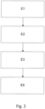
figure 2 , un ordinogramme d'un mode de réalisation du procédé selon l'invention ; - la
figure 3 , un premier exemple de réalisation du procédé selon l'invention ; - la
figure 4 , un deuxième exemple de réalisation du procédé selon l'invention. - Sauf précision contraire, un même élément apparaissant sur des figures différentes présente une référence unique.
- Selon un premier mode de réalisation illustré dans les
figures 1A-B et2 , l'invention concerne un dispositif électronique DE comprenant une mémoire non-volatile MN, une mémoire vive MV et une puce d'affichage PA, ladite puce d'affichage PA comportant un registre de sortie vidéo RV et un registre d'affichage RA. L'invention concerne également un procédé d'affichage à l'aide d'une puce d'affichage destiné à être mise en oeuvre dans un tel dispositif électronique. - La mémoire vive MV peut consister en une mémoire dédiée de la puce PA ou bien encore à une mémoire RAM (pour Random Access Memory en anglais) destinée à un système d'exploitation. La mémoire non-volatile MN peut consister en un disque dur ou une mémoire flash.
- Le procédé selon l'invention comprend une première phase de programmation statique comportant une étape E1 de configuration du registre de sortie vidéo RV. Cette étape peut par exemple consister en une configuration du registre de sortie vidéo RV de sorte à obtenir un affichage progressif ou entrelacé.
- La première phase du procédé comprend en outre une étape E2 d'écriture de n images dans la mémoire vive MV, n étant un entier supérieur ou égal à deux. Une animation se composant d'au moins deux images, il est en effet nécessaire dans cette étape que l'écriture concerne au moins deux images. Ainsi, lors de cette étape, les images composant l'animation sont recopiées de la mémoire non-volatile MN vers la mémoire vive MV.
- La première phase du procédé comprend en outre une étape E3 d'écriture dans la mémoire vive d'une pluralité de noeuds Ni. On entend ici par pluralité de noeuds Ni une table chainée de configuration de sorte que chaque noeud Ni comprend l'adresse en mémoire vive Nin d'au moins une partie d'une image ainsi que l'adresse en mémoire vive Nir du noeud suivant, le dernier noeud comprenant alors l'adresse en mémoire vive du premier noeud N1.
- La première phase du procédé comprend également une étape E4 de configuration du registre d'affichage RA. Cette étape peut consister à copier dans le registre d'affichage RA le premier noeud de la pluralité de noeuds Ni chargée en mémoire vive.
- Le procédé selon l'invention comprend également une deuxième phase de lecture des n images par ladite puce d'affichage (PA), ladite lecture se faisant à l'aide du registre d'affichage (RA) de sorte à afficher ladite animation.
- Dans le procédé selon l'invention, la configuration des registres s'effectue de manière statique. Autrement dit, une fois configurés, les registres ne sont plus reconfigurés et l'animation se produit en tirant avantage du fonctionnement de la puce d'affichage. Autrement dit, le procédé selon l'invention peut être utilisé sans adaptation particulière de la puce d'affichage et permet à cette dernière d'afficher une animation à travers une configuration statique du registre d'affichage et du registre de sortie vidéo.
- En effet, comme expliqué précédemment, la puce d'affichage PA affiche l'image ou la partie d'image dont l'adresse est comprise dans un premier noeud chargé dans le registre d'affichage RA. Une fois cette image ou cette partie d'image affichée, un deuxième noeud dont l'adresse en mémoire vive MV est comprise dans le premier noeud est à son tour chargé dans le registre d'affichage RA. De cette manière, la puce copie depuis la mémoire vive dans le registre d'affichage de manière successive les noeuds de la pluralité de noeuds Ni.
- On comprend donc que l'étape E3 d'écriture de la pluralité de noeuds Ni est fonction du mode d'affichage choisi lors de l'étape E1 de configuration du registre de sortie vidéo RV.
- Dans un mode de réalisation, le mode d'affichage est un mode d'affichage progressif. L'étape d'écriture E3 de la pluralité de noeuds Ni est alors effectuée de sorte que chaque noeud Ni comprend l'adresse Nin d'une image ainsi que l'adresse Nir du noeud suivant, le dernier noeud comprenant l'adresse du premier noeud N1. En configurant les noeuds Ni de la sorte et l'affichage se faisant en mode progressif, la lecture d'un noeud Ni par la puce d'affichage PA conduit à l'affichage d'une image. Chaque noeud Ni étant relatif à une image, l'animation va se faire par la lecture, par la puce d'affichage PA, de la pluralité de noeuds Ni. En prenant l'exemple d'une vitesse de rafraichissement de 60Hz, la vitesse maximale d'animation est donc de 30 cycles par seconde. On peut cependant envisager de configurer les noeuds Ni de sortes qu'une pluralité de noeuds pointe vers une même image afin de pouvoir moduler la vitesse d'animation.
- Dans un exemple de réalisation illustré à la
figure 3 , le premier noeud N1 comporte l'adresse en mémoire vive N1n de l'image I1 ainsi que l'adresse en mémoire vive du noeud suivant N2. Le noeud N2 comprend l'adresse en mémoire vive de l'image 11 ainsi que l'adresse en mémoire vive du noeud suivant N3. Le troisième noeud N3 comprend l'adresse mémoire vive de l'image I2 ainsi que l'adresse mémoire vive du noeud N4. Le noeud N4 comprend l'adresse mémoire vive de l'image I2 ainsi que l'adresse en mémoire vive du premier noeud N1, le noeud N4 étant le dernier noeud de la pluralité de noeuds. En parcourant les quatre noeuds N1, N2, N3, N4, la puce d'affichage PA affiche successivement et de manière cyclique deux images 11, I2 produisant ainsi une animation. Dans le cas où la vitesse de rafraichissement est de 60Hz, on obtient ainsi une animation d'une durée de 1/15 de seconde, autrement dit 15 cycles d'animation par seconde. On peut également configurer les noeuds de sorte que les 30 premiers noeuds comprennent l'adresse en mémoire vive d'une première image et les 30 noeuds suivants comprennent l'adresse en mémoire vive d'une deuxième image. Dans ce cas, la vitesse d'animation n'est plus que de 2 images par seconde, autrement dit un cycle d'animation par seconde. Ainsi, le déroulé de l'animation peut être modulé en modifiant le nombre de noeuds comportant l'adresse en mémoire vive des différentes images composant l'animation. - Dans un mode de réalisation alternatif, le mode d'affichage est un mode d'affichage entrelacé et chaque image est divisée en une première trame dite trame impaire comprenant les lignes impaires de l'image et une deuxième trame dite trame paire comprenant les lignes paires de l'image. L'étape d'écriture E3 de la pluralité de noeuds Ni est alors effectuée de sorte que chaque noeud Ni comprend l'adresse en mémoire vive Nin d'une trame d'une image ainsi que l'adresse en mémoire vive Nir du noeud suivant, le dernier noeud comprenant l'adresse en mémoire vive Nir du premier noeud N1. En configurant les noeuds Ni de la sorte, on s'assure que les trames des images vont être affichées les unes après les autres. L'affichage se faisant en mode entrelacé, la lecture d'un noeud Ni conduit à l'affichage d'une trame. Il faut donc parcourir deux noeuds pour afficher une image. Chaque noeud Ni étant relatif à une trame d'une image, l'animation comprenant n images va se faire par la lecture d'au moins 2n noeuds.
- Dans un exemple illustré à la
figure 4 , les noeuds N1 et N3 correspondent chacun à une trame impaire Tl et les noeuds N2 et N4 correspondent chacun à une trame paire TP. Le premier noeud N1 comprend l'adresse en mémoire vive N1n de la trame impaire I1TI d'une première image I1 ainsi que l'adresse en mémoire vive N1r du deuxième noeud N2. Le deuxième noeud N2 comprend l'adresse mémoire vive de la trame paire I1TP de l'image I1 ainsi que l'adresse mémoire vive du noeud N3. Le noeud N3 comprend l'adresse en mémoire vive de la trame impaire I2TI d'une deuxième image I2 ainsi que l'adresse en mémoire vive du quatrième noeud N4. Le noeud N4 comprend l'adresse en mémoire vive de la trame paire I2TP de l'image I2 ainsi que l'adresse en mémoire vive du premier noeud N1, le noeud N4 étant le dernier noeud. Si l'on suppose un rafraichissement de l'affichage de 60Hz, on obtient une alternance entre les deux images toutes les 1/15 de seconde. Autrement dit, la vitesse maximale d'animation est de 15 cycles par seconde. On peut cependant envisager de configurer les noeuds Ni de sorte qu'une pluralité de noeuds Ni pointe vers une même image afin de pouvoir moduler la vitesse d'animation. Autrement dit, un premier noeud pointe vers la trame impaire d'une image et le noeud suivant pointe vers la trame paire de la même image, et ce de manière répétée sur plusieurs couples de noeuds consécutifs. On peut par exemple configurer les noeuds de sorte que les 30 premiers noeuds pointent vers une première image (15 des noeuds pointant vers la trame impaire de la première image et 15 noeuds pointant vers la trame paire de la première image) et les 30 noeuds suivants pointent vers une deuxième image (15 des noeuds pointant vers la trame impaire de la première image et 15 noeuds pointant vers la trame paire de la première image). Alors, la vitesse d'animation n'est plus que de 2 images par seconde. Autrement dit, la vitesse d'animation n'est plus que de 1 cycle par seconde. - Quel que soit le mode d'affichage choisi, l'étape E2 d'écriture de n images dans la mémoire vive RV peut se faire de deux manières distinctes.
- Dans un mode de réalisation, un programme de démarrage est en charge du chargement en mémoire d'un système d'exploitation et les n images sont stockées dans ledit programme de démarrage. Ces dernières sont donc écrites en mémoire vive MV en même temps que le programme de démarrage. Autrement dit, dans ce mode de réalisation, le chargement des images en mémoire vive MV est effectué par le système élémentaire d'entrée/sortie. Les images étant disponibles dès le chargement en mémoire du programme de démarrage, le système élémentaire d'entrée/sortie peut être également en charge de l'étape de configuration des registres ce qui permet d'avoir un affichage de l'animation dès les premiers instants du démarrage immédiatement après le chargement du programme de démarrage, et donc des images, dans la mémoire vive MV. Ce mode de réalisation permet de charger en mémoire l'ensemble des éléments nécessaires à l'affichage en une seule étape. Le système élémentaire d'entrée/sortie pourra être un BIOS (de l'anglais Basic Input Output System) ou bien un coprocesseur de sécurité. On entend par coprocesseur de sécurité une unité logique en charge de l'initialisation de la mémoire vive MV, de la vérification du programme de démarrage par vérification d'une empreinte de ce dernier, et de la mise en mémoire vive MV du programme de démarrage. Cependant, si le nombre ou la résolution des images est élevé, la taille mémoire du programme de démarrage auquel ont été incorporées les images peut devenir importante ce qui peut ralentir l'opération de vérification de l'intégrité du programme de démarrage par le système élémentaire d'entrée/sortie.
- On peut alors envisager un autre mode de réalisation dans lequel les n images sont stockées dans la mémoire non-volatile MN du dispositif électronique DE indépendamment du programme de démarrage et sont chargées en mémoire vive MV après le chargement du programme de démarrage par ledit programme de démarrage. Ainsi, l'empreinte mémoire du programme de démarrage est réduite. Dans ce mode de réalisation, le programme de démarrage peut être en charge de la configuration des registres de sortie vidéo RV et d'affichage RA.
- Dans un mode de réalisation, les n images sont stockées sous forme d'images compressées ce qui permet de réduire l'empreinte mémoire des images. On peut par exemple envisager un algorithme de compression de type à codage par plage ou LRE (pour Run Length Encoding en anglais). De manière plus générale, tout algorithme de compression supporté par la puce d'affichage PA peut être utilisé. Il peut donc s'agir également d'un algorithme de compression propriétaire.
- Dans un mode de réalisation, l'écriture des n images dans la mémoire vive se fait dans une zone dédiée de la mémoire vive MV. Ceci permet de conserver les images en mémoire une fois le système d'exploitation chargé en prévenant tout écrasement des images par au moins une partie du code du système d'exploitation. En effet, il existe un délai entre le moment où le système d'exploitation est chargé en mémoire et le moment où le système d'exploitation prend effectivement le contrôle de la puce d'affichage PA. S'assurer que les images restent en mémoire après le chargement du système d'exploitation permet de garantir que l'animation restera affichée jusqu'à la prise de contrôle effective de la puce d'affichage par le système d'exploitation.
- Dans un mode de réalisation, l'animation peut être décomposée en un premier plan graphique et un deuxième plan graphique, le premier plan graphique constituant la partie fixe de l'animation et le deuxième plan graphique constituant la partie changeante de l'animation, la puce d'affichage comportant des moyens pour superposer le premier plan graphique au deuxième plan graphique.
- Lorsque l'affichage s'effectue en mode progressif, l'étape d'écriture dans la mémoire vive d'une pluralité de noeuds comprend alors deux sous-étapes :
- une première sous-étape d'écriture d'un noeud comprenant l'adresse en mémoire vive MV d'une image destinée à être affichée dans le premier plan graphique, le noeud comprenant en outre sa propre adresse en mémoire vive ;
- une deuxième sous-étape d'écriture d'une pluralité de noeuds Ni, chaque noeud comprenant l'adresse en mémoire vive MV d'une image destinée à être affichée dans le deuxième plan graphique ainsi que l'adresse en mémoire vive MV du noeud suivant, le dernier noeud comprenant l'adresse en mémoire vive MV du premier noeud.
- De manière alternative, lorsque l'affichage s'effectue en mode entrelacé, l'étape d'écriture dans la mémoire vive d'une pluralité de noeuds comprend deux sous-étapes :
- une première sous-étape d'écriture d'un premier noeud et d'un deuxième noeud, le premier noeud comprenant l'adresse en mémoire vive MV de la trame impaire d'une image destinée à être affichée dans le premier plan graphique ainsi que l'adresse en mémoire vive MV du deuxième noeud, le deuxième noeud comprenant l'adresse en mémoire vive MV de la trame paire de l'image destinée à être affichée dans le premier plan graphique ainsi que l'adresse en mémoire vive MV du premier noeud ;
- une deuxième sous-étape d'écriture d'une pluralité de noeuds Ni, chaque noeud impair comprenant l'adresse en mémoire vive MV de la trame impaire d'une image destinée à être affichée dans le deuxième plan graphique et chaque noeud pair comprenant l'adresse en mémoire vive MV de la trame paire d'une image destinée à être affichée dans le deuxième plan graphique, le dernier noeud comprenant l'adresse en mémoire vive MV du premier noeud.
- Ainsi, dans ces deux modes alternatifs de réalisation, l'animation n'est possible que dans la mesure où le nombre d'images est supérieur à trois. En effet, l'animation se décompose en deux parties : une première partie relative aux éléments fixes de l'animation qui viendra constituer le premier plan graphique, une deuxième partie relative aux éléments mobile de l'animation. Par exemple, dans le cas d'une animation comportant un fond sur lequel un point clignote, le premier plan sera constitué du fond et le deuxième plan graphique sera constitué du point clignotant. Dans cet exemple, l'affichage du fond, c'est-à-dire du premier plan graphique, se fera à l'aide d'un noeud unique ou un couple de noeud comportant l'adresse en mémoire vive de l'image du fond tandis que l'affichage du deuxième plan graphique se fera à l'aide de d'une pluralité de noeuds Ni comme expliqué précédemment. Il s'agit bien entendu d'un exemple et on pourra envisager un deuxième plan constitué d'une animation plus complexe comportant un nombre d'images plus important éventuellement associé à un nombre de noeuds plus grand.
- Dans ces deux modes de réalisation alternatif, l'étape E4 de configuration du registre d'affichage RA peut consister à attribuer un emplacement mémoire du registre d'affichage RA à chaque plan graphique, à copier dans un premier emplacement du registre d'affichage RA le noeud (dans le cas d'un affichage progressif) ou le premier noeud du couple de noeuds (dans le cas d'un affichage entrelacé) correspondant au premier plan graphique et à copier dans un deuxième emplacement mémoire du registre d'affichage RA le premier noeud de la pluralité de noeuds Ni chargée en mémoire vive MV correspondant au deuxième plan graphique. La lecture de chacun de ces emplacements mémoire s'effectue de la même manière que dans le cas d'un plan graphique unique décrit précédemment, c'est-à-dire en affichant l'image ou la trame de l'image dont l'adresse en mémoire vive MV est contenue dans un premier noeud et en chargeant ensuite le noeud suivant dont l'adresse en mémoire vive MV est contenue dans le premier noeud. La lecture se faisant simultanément sur les deux emplacements mémoire, on obtient l'affichage de deux plans graphiques, le deuxième plan graphique venant se superposer au premier plan graphique.
Claims (12)
- Procédé d'affichage d'une animation par une puce d'affichage (PA) d'un dispositif électronique (DE), ledit dispositif électronique (DE) comprenant une mémoire non-volatile (MN) et une mémoire vive (MV), ladite puce d'affichage (PA) comportant un registre de sortie vidéo (RV) et un registre d'affichage (RA) ; le procédé étant exécuté au démarrage du dispositif (DE) et étant caractérisé en ce qu'il comprend une première phase de programmation comprenant :- une étape (E1) de configuration du registre de sortie vidéo (RV),_qui est effectuée de sorte que l'affichage se fait soit en mode progressif, soit en mode entrelacé ;- une étape (E2) d'écriture de n images dans la mémoire vive (MV), n étant un entier supérieur ou égal à deux, les n images formant, lorsqu'elles sont affichées successivement, l'animation à afficher ;- une étape (E3) d'écriture dans la mémoire vive (MV) d'une pluralité de noeuds (Ni) de sorte que chaque noeud comprend l'adresse en mémoire vive (MV) d'au moins une trame d'une image parmi les n images ainsi que l'adresse en mémoire vive (MV) du noeud suivant, le dernier noeud comprenant l'adresse en mémoire vive (MV) du premier noeud, l'étape E3 étant fonction d'un mode d'affichage choisi lors de l'étape E1 ;- une étape (E4) de configuration du registre d'affichage (RA) lors de laquelle un noeud de la pluralité de noeuds (Ni) est copié dans le registre d'affichage (RA) ;et en ce qu'il comprend ensuite une deuxième phase de lecture des n images par ladite puce d'affichage (PA), la phase de lecture comprenant :- une étape d'affichage, par la puce d'affichage (PA), de l'image ou la trame d'image dont l'adresse est comprise dans le noeud de la pluralité de noeuds (Ni) chargé dans le registre d'affichage (RA), dit noeud chargé ;- puis, une fois cette image ou cette trame d'image affichée, une étape de chargement dans registre d'affichage (RA), par la puce d'affichage (PA), du noeud dont l'adresse en mémoire vive (MV) est comprise dans le noeud chargé ;ces deux étapes répétées de sorte à parcourir la pluralité de noeuds (Ni) et ainsi afficher l'animation obtenue par l'affichage successif des n images.
- Procédé selon la revendication précédente caractérisé en ce qu'un programme de démarrage en charge du démarrage d'un système d'exploitation est stocké dans la mémoire non-volatile (MN), en ce que le dispositif électronique (DE) comporte un système élémentaire d'entrée/sortie configuré pour charger en mémoire vive (MV) ledit programme de démarrage et en ce que les n images sont incluses dans ledit programme de démarrage de manière que l'étape (E3) d'écriture des n images dans la mémoire vive (MV) se fait lors du chargement dudit programme de démarrage par ledit système élémentaire d'entrée/sortie.
- Procédé selon la revendication 1 caractérisé en ce qu'un programme de démarrage en charge du démarrage d'un système d'exploitation est stocké dans la mémoire non-volatile (MN), en ce que le dispositif électronique (DE) comporte un système élémentaire d'entrée/sortie configuré pour charger en mémoire vive (MV) ledit programme de démarrage, en ce que les n images sont stockées dans la mémoire non-volatile (MN) et en ce que l'étape d'écriture (E3) des n images dans la mémoire vive se fait par copie des images stockées dans la mémoire non-volatile (MN) vers la mémoire vive (MV) par ledit programme de démarrage.
- Procédé selon l'une des revendications précédentes caractérisé en ce que les n images sont stockées sous forme compressée.
- Procédé selon l'une des revendications précédentes caractérisé en ce que l'écriture des n images dans la mémoire vive (MV) se fait dans une zone dédiée de ladite mémoire vive (MV).
- Procédé selon l'une des revendications précédentes caractérisé en ce que la configuration du registre de sortie vidéo (RV) lors de l'étape (E1) de configuration du registre de sortie vidéo (RV) est effectuée de sorte que l'affichage se fait en mode progressif et en ce que chaque noeud comprend l'adresse en mémoire vive (MV) d'une image.
- Procédé selon la revendication précédente caractérisé en ce que l'animation est décomposée en un premier plan graphique et un deuxième plan graphique, le premier plan graphique constituant la partie fixe de l'animation et le deuxième plan graphique constituant la partie changeante de l'animation, la puce d'affichage (PA) comportant des moyens pour superposer le premier plan graphique au deuxième plan graphique ; et en ce que l'étape (E3) d'écriture dans la mémoire vive (MV) d'une pluralité de noeuds (Ni) comprend deux sous-étapes :- une première sous-étape d'écriture d'un noeud comprenant l'adresse en mémoire vive (MV) d'une image destinée à être affichée dans le premier plan graphique, le noeud comprenant en outre sa propre adresse en mémoire vive (MV) ;- une deuxième sous-étape d'écriture d'une pluralité de noeuds (Ni), chaque noeud comprenant l'adresse en mémoire vive (MV) d'une image destinée à être affichée dans le deuxième plan graphique ainsi que l'adresse en mémoire vive (MV) du noeud suivant, le dernier noeud comprenant l'adresse en mémoire vive (MV) du premier noeud.
- Procédé selon l'une des revendications 1 à 5 caractérisé en ce que la configuration du registre de sortie vidéo (RV) lors de l'étape de configuration du registre de sortie vidéo (RV) est effectuée de sorte que l'affichage se fait en mode entrelacé, en ce que la pluralité de noeuds (Ni) comporte des noeuds pairs et des noeuds impairs, et en ce que chaque noeud impair comprend l'adresse en mémoire vive (MV) d'une trame impaire d'une image et chaque noeud pair comprend l'adresse en mémoire vive (MV) d'une trame paire d'une image.
- Procédé selon la revendication précédente caractérisé en ce que l'animation est décomposée en un premier plan graphique et un deuxième plan graphique, le premier plan graphique constituant la partie fixe de l'animation et le deuxième plan graphique constituant la partie changeante de l'animation, la puce d'affichage (PA) comportant des moyens pour superposer le premier plan graphique au deuxième plan graphique ; et en ce que l'étape (E3) d'écriture dans la mémoire vive (MV) d'une pluralité de noeuds (Ni) comprend deux sous-étapes :- une première sous-étape d'écriture d'un premier noeud et d'un deuxième noeud, le premier noeud comprenant l'adresse en mémoire (MV) vive de la trame impaire d'une image destinée à être affichée dans le premier plan graphique ainsi que l'adresse en mémoire vive (MV) du deuxième noeud, le deuxième noeud comprenant l'adresse en mémoire vive (MV) de la trame paire de l'image destinée à être affichée dans le premier plan graphique ainsi que l'adresse en mémoire vive (MV) du premier noeud ;- une deuxième sous-étape d'écriture d'une pluralité de noeuds (Ni), chaque noeud impair comprenant l'adresse en mémoire vive (MV) de la trame impaire d'une image destinée à être affichée dans le deuxième plan graphique et chaque noeud pair comprenant l'adresse en mémoire vive (MV) de la trame paire d'une image destinée à être affichée dans le deuxième plan graphique, le dernier noeud comprenant l'adresse en mémoire vive (MV) du premier noeud.
- Dispositif électronique (DE) comprenant une mémoire non-volatile (MN), une mémoire vive (MV) et une puce d'affichage (PA), ladite puce d'affichage (PA) comportant un registre de sortie vidéo (RV) et un registre d'affichage (RA) ; le dispositif étant caractérisé en ce qu'il comprend en outre des moyens pour la mise en oeuvre du procédé selon l'une quelconque des revendications 1 à 9.
- Produit programme d'ordinateur comprenant des instructions qui conduisent le dispositif selon la revendication 10 à exécuter les étapes du procédé selon l'une des revendications 1 à 9.
- Support lisible par ordinateur, sur lequel est enregistré le programme d'ordinateur selon la revendication 11.
Applications Claiming Priority (2)
| Application Number | Priority Date | Filing Date | Title |
|---|---|---|---|
| FR1651662A FR3048293B1 (fr) | 2016-02-29 | 2016-02-29 | Procede de programmation d'une animation lors de la phase de demarrage d'un dispositif electronique et dispositif electronique associe |
| PCT/EP2017/054491 WO2017148856A1 (fr) | 2016-02-29 | 2017-02-27 | Procede de d'affichage d'une animation lors de la phase de demarrage d'un dispositif electronique et dispositif electronique associe |
Publications (2)
| Publication Number | Publication Date |
|---|---|
| EP3423978A1 EP3423978A1 (fr) | 2019-01-09 |
| EP3423978B1 true EP3423978B1 (fr) | 2024-12-25 |
Family
ID=56555457
Family Applications (1)
| Application Number | Title | Priority Date | Filing Date |
|---|---|---|---|
| EP17707038.0A Active EP3423978B1 (fr) | 2016-02-29 | 2017-02-27 | Procede de d'affichage d'une animation lors de la phase de demarrage d'un dispositif electronique et dispositif electronique associe |
Country Status (5)
| Country | Link |
|---|---|
| US (1) | US11523180B2 (fr) |
| EP (1) | EP3423978B1 (fr) |
| CN (1) | CN108780483B (fr) |
| FR (1) | FR3048293B1 (fr) |
| WO (1) | WO2017148856A1 (fr) |
Families Citing this family (4)
| Publication number | Priority date | Publication date | Assignee | Title |
|---|---|---|---|---|
| WO2019112615A1 (fr) * | 2017-12-08 | 2019-06-13 | Hewlett-Packard Development Company, L.P. | Affichages virtualisés privés |
| CN109445860B (zh) * | 2018-10-17 | 2022-03-25 | 京东方科技集团股份有限公司 | 引导电子设备系统开机的方法,电子设备,可读存储介质 |
| TWI773430B (zh) * | 2021-07-09 | 2022-08-01 | 新唐科技股份有限公司 | 安全啟動系統及其方法 |
| CN121388321B (zh) * | 2025-12-23 | 2026-03-06 | 深圳市东信时代信息技术有限公司 | 基于可导出配置对象的动画编排方法、设备和存储介质 |
Family Cites Families (24)
| Publication number | Priority date | Publication date | Assignee | Title |
|---|---|---|---|---|
| US4404554A (en) * | 1980-10-06 | 1983-09-13 | Standard Microsystems Corp. | Video address generator and timer for creating a flexible CRT display |
| KR960004655B1 (ko) * | 1990-02-05 | 1996-04-11 | 가부시키가이샤 리코 | 동화 표시 장치 및 그것에 이용되는 외부 메모리 |
| US6560702B1 (en) * | 1997-12-10 | 2003-05-06 | Phoenix Technologies Ltd. | Method and apparatus for execution of an application during computer pre-boot operation |
| US6178503B1 (en) * | 1998-09-11 | 2001-01-23 | Powerquest Corporation | Managing multiple operating systems on a single computer |
| US6556193B1 (en) * | 1999-04-02 | 2003-04-29 | Teralogic, Inc. | De-interlacing video images using patch-based processing |
| US6791572B1 (en) * | 1999-06-18 | 2004-09-14 | Phoenix Technologies Ltd. | Generating media output during BIOS boot-up |
| US20020135585A1 (en) * | 2000-02-01 | 2002-09-26 | Dye Thomas A. | Video controller system with screen caching |
| US7176870B2 (en) * | 2001-12-27 | 2007-02-13 | Renesas Technology Corp. | Display drive control circuit |
| TWI286703B (en) * | 2005-07-22 | 2007-09-11 | Mitac Technology Corp | Method using foreground image data to display and background program to load and execute computer program |
| US20070110408A1 (en) * | 2005-11-14 | 2007-05-17 | Chi-Lun Chang | Device for displaying boot animation of optical disc player and method thereof |
| US8106917B2 (en) * | 2006-06-29 | 2012-01-31 | Broadcom Corporation | Method and system for mosaic mode display of video |
| CN1917571A (zh) * | 2006-09-15 | 2007-02-21 | 中辉世纪传媒发展有限公司 | 一种数字广播电视系统、机顶盒及开机画面显示方法 |
| US7987348B2 (en) * | 2007-03-30 | 2011-07-26 | Intel Corporation | Instant on video |
| US20100079472A1 (en) * | 2008-09-30 | 2010-04-01 | Sean Shang | Method and systems to display platform graphics during operating system initialization |
| JP5180874B2 (ja) * | 2009-02-27 | 2013-04-10 | 株式会社日立製作所 | バッファ管理方法、及びパケット通信装置 |
| CN101668084A (zh) * | 2009-09-18 | 2010-03-10 | 中兴通讯股份有限公司 | 一种移动终端中的个性化动画实现方法及装置 |
| CN101827199A (zh) * | 2010-04-06 | 2010-09-08 | 福建新大陆通信科技有限公司 | 通过外部存储介质实现机顶盒开机画面更换的方法 |
| US8521948B2 (en) * | 2011-01-03 | 2013-08-27 | Apple Inc. | Handling dynamic and static data for a system having non-volatile memory |
| US9883156B2 (en) * | 2011-11-30 | 2018-01-30 | Intel Corporation | Techniques to display multimedia data during operating system initialization |
| CN102768819B (zh) * | 2012-07-17 | 2014-12-10 | 中国兵器工业集团第二一四研究所苏州研发中心 | Oled实时显示驱动控制系统及其控制方法 |
| CN103581409A (zh) * | 2012-07-24 | 2014-02-12 | 上海斐讯数据通信技术有限公司 | 一种自定义开关机界面的方法和移动终端 |
| CN103150178A (zh) * | 2013-02-05 | 2013-06-12 | 联发科技(新加坡)私人有限公司 | 一种开机显示控制方法及处理器芯片 |
| US9778937B1 (en) * | 2013-10-16 | 2017-10-03 | American Megatrends, Inc. | Method and implementation for starting and stopping the playing of media content during booting process |
| US9342859B2 (en) * | 2013-10-22 | 2016-05-17 | American Megatrends, Inc. | GPU based parallel image processing at thin client |
-
2016
- 2016-02-29 FR FR1651662A patent/FR3048293B1/fr not_active Expired - Fee Related
-
2017
- 2017-02-27 CN CN201780017378.4A patent/CN108780483B/zh active Active
- 2017-02-27 US US16/080,394 patent/US11523180B2/en active Active
- 2017-02-27 WO PCT/EP2017/054491 patent/WO2017148856A1/fr not_active Ceased
- 2017-02-27 EP EP17707038.0A patent/EP3423978B1/fr active Active
Also Published As
| Publication number | Publication date |
|---|---|
| CN108780483A (zh) | 2018-11-09 |
| WO2017148856A1 (fr) | 2017-09-08 |
| US11523180B2 (en) | 2022-12-06 |
| EP3423978A1 (fr) | 2019-01-09 |
| US20190087200A1 (en) | 2019-03-21 |
| FR3048293A1 (fr) | 2017-09-01 |
| FR3048293B1 (fr) | 2018-07-06 |
| BR112018067555A2 (pt) | 2019-01-08 |
| CN108780483B (zh) | 2022-10-11 |
Similar Documents
| Publication | Publication Date | Title |
|---|---|---|
| FR2554256A1 (fr) | Appareil et procede de regeneration d'un tampon de trames fonctionnant a grande vitesse | |
| US8605081B2 (en) | Converting 3D data to hogel data | |
| US20100156895A1 (en) | Processing Pre-recorded Hogel Data | |
| EP3423978A1 (fr) | Procede de d'affichage d'une animation lors de la phase de demarrage d'un dispositif electronique et dispositif electronique associe | |
| FR2964236A1 (fr) | Dispositif et procede de generation d'images multifenetres a priorite variable | |
| EP1432246B1 (fr) | Procede et dispositif de decodage et d'affichage en marche arriere d'images mpeg, circuit pilote video et boitier decodeur incorporant un tel dispositif | |
| EP1860571B1 (fr) | Contrôleur de DMA, système sur puce comprenant un tel contrôleur de DMA, procédé d'échange de données par l'intermédiaire d'un tel contrôleur de DMA | |
| FR2583904A1 (fr) | Systeme d'ordinateur du type a trains multiples de donnees et instruction unique (simd), avec traitement selectif des donnees | |
| EP3686874B1 (fr) | Système d'affichage à résolution variable | |
| KR101807229B1 (ko) | Tv 영상용 가속 초해상 처리 방법 및 이 방법에 따른 tv 영상용 가속 초해상 처리 장치, 제1~6 가속 초해상 처리 프로그램과 제1~2 기억 매체 | |
| CN119313797A (zh) | 全景影像的渲染方法、装置、车辆、介质及产品 | |
| CN118552394A (zh) | 图像处理方法、装置及电子设备 | |
| US12254405B2 (en) | Processing data in pixel-to-pixel neural networks | |
| EP0020980B1 (fr) | Dispositif d'affichage par segments | |
| FR2948473A1 (fr) | Circuit d'interface comportant une memoire de type fifo | |
| EP1752857B1 (fr) | Générateur de signal de forme d'onde modifiable | |
| EP1249760A1 (fr) | Dispositif de traitement de données par plusieurs processeurs | |
| EP0680015B1 (fr) | Dispositif d'alimentation en pixels d'une série d'opérateurs d'un circuit de compression d'images mobiles | |
| FR2836588A1 (fr) | Procede d'affichage numerique d'image et dispositif d'affichage numerique | |
| CN114327322A (zh) | 图层显示方法及其装置 | |
| WO2016071330A1 (fr) | Procede et dispositif d'architecture configurable a gros grains pour executer en integralite un code applicatif | |
| WO2025245716A1 (fr) | Variabilité d'enregistrement et de compensation anti-vieillissement d'oled | |
| EP0391785B1 (fr) | Dispositif et procédé d'écriture dans un dispositif de mémorisation de type pile | |
| CN112866780B (zh) | 字幕循环显示方法及装置、视频处理设备系统和存储介质 | |
| EP0973145A1 (fr) | Procédé et système d'élaboration d'images numériques résultant d'éléments graphiques auxiliaires incrustés dans des images principales |
Legal Events
| Date | Code | Title | Description |
|---|---|---|---|
| STAA | Information on the status of an ep patent application or granted ep patent |
Free format text: STATUS: UNKNOWN |
|
| STAA | Information on the status of an ep patent application or granted ep patent |
Free format text: STATUS: THE INTERNATIONAL PUBLICATION HAS BEEN MADE |
|
| PUAI | Public reference made under article 153(3) epc to a published international application that has entered the european phase |
Free format text: ORIGINAL CODE: 0009012 |
|
| STAA | Information on the status of an ep patent application or granted ep patent |
Free format text: STATUS: REQUEST FOR EXAMINATION WAS MADE |
|
| 17P | Request for examination filed |
Effective date: 20180924 |
|
| AK | Designated contracting states |
Kind code of ref document: A1 Designated state(s): AL AT BE BG CH CY CZ DE DK EE ES FI FR GB GR HR HU IE IS IT LI LT LU LV MC MK MT NL NO PL PT RO RS SE SI SK SM TR |
|
| AX | Request for extension of the european patent |
Extension state: BA ME |
|
| DAV | Request for validation of the european patent (deleted) | ||
| DAX | Request for extension of the european patent (deleted) | ||
| STAA | Information on the status of an ep patent application or granted ep patent |
Free format text: STATUS: EXAMINATION IS IN PROGRESS |
|
| 17Q | First examination report despatched |
Effective date: 20210430 |
|
| RAP3 | Party data changed (applicant data changed or rights of an application transferred) |
Owner name: SAGEMCOM BROADBAND SAS |
|
| RIN1 | Information on inventor provided before grant (corrected) |
Inventor name: BELLANGER, JULIEN |
|
| REG | Reference to a national code |
Ref country code: DE Ref legal event code: R079 Ref document number: 602017086933 Country of ref document: DE Free format text: PREVIOUS MAIN CLASS: G06F0021510000 Ipc: H04L0049901500 |
|
| GRAP | Despatch of communication of intention to grant a patent |
Free format text: ORIGINAL CODE: EPIDOSNIGR1 |
|
| STAA | Information on the status of an ep patent application or granted ep patent |
Free format text: STATUS: GRANT OF PATENT IS INTENDED |
|
| RIC1 | Information provided on ipc code assigned before grant |
Ipc: G09G 5/393 20060101ALI20240703BHEP Ipc: G09G 5/395 20060101ALI20240703BHEP Ipc: G06F 3/14 20060101ALI20240703BHEP Ipc: G06T 13/00 20110101ALI20240703BHEP Ipc: G06F 9/445 20180101ALI20240703BHEP Ipc: G09G 5/00 20060101ALI20240703BHEP Ipc: G06F 9/44 20180101ALI20240703BHEP Ipc: H04L 49/9015 20220101AFI20240703BHEP |
|
| INTG | Intention to grant announced |
Effective date: 20240717 |
|
| GRAS | Grant fee paid |
Free format text: ORIGINAL CODE: EPIDOSNIGR3 |
|
| GRAA | (expected) grant |
Free format text: ORIGINAL CODE: 0009210 |
|
| STAA | Information on the status of an ep patent application or granted ep patent |
Free format text: STATUS: THE PATENT HAS BEEN GRANTED |
|
| AK | Designated contracting states |
Kind code of ref document: B1 Designated state(s): AL AT BE BG CH CY CZ DE DK EE ES FI FR GB GR HR HU IE IS IT LI LT LU LV MC MK MT NL NO PL PT RO RS SE SI SK SM TR |
|
| REG | Reference to a national code |
Ref country code: GB Ref legal event code: FG4D Free format text: NOT ENGLISH |
|
| REG | Reference to a national code |
Ref country code: CH Ref legal event code: EP |
|
| REG | Reference to a national code |
Ref country code: DE Ref legal event code: R096 Ref document number: 602017086933 Country of ref document: DE |
|
| REG | Reference to a national code |
Ref country code: IE Ref legal event code: FG4D Free format text: LANGUAGE OF EP DOCUMENT: FRENCH |
|
| REG | Reference to a national code |
Ref country code: LT Ref legal event code: MG9D |
|
| PG25 | Lapsed in a contracting state [announced via postgrant information from national office to epo] |
Ref country code: HR Free format text: LAPSE BECAUSE OF FAILURE TO SUBMIT A TRANSLATION OF THE DESCRIPTION OR TO PAY THE FEE WITHIN THE PRESCRIBED TIME-LIMIT Effective date: 20241225 |
|
| PGFP | Annual fee paid to national office [announced via postgrant information from national office to epo] |
Ref country code: DE Payment date: 20250122 Year of fee payment: 9 |
|
| PG25 | Lapsed in a contracting state [announced via postgrant information from national office to epo] |
Ref country code: FI Free format text: LAPSE BECAUSE OF FAILURE TO SUBMIT A TRANSLATION OF THE DESCRIPTION OR TO PAY THE FEE WITHIN THE PRESCRIBED TIME-LIMIT Effective date: 20241225 |
|
| PG25 | Lapsed in a contracting state [announced via postgrant information from national office to epo] |
Ref country code: BG Free format text: LAPSE BECAUSE OF FAILURE TO SUBMIT A TRANSLATION OF THE DESCRIPTION OR TO PAY THE FEE WITHIN THE PRESCRIBED TIME-LIMIT Effective date: 20241225 |
|
| PG25 | Lapsed in a contracting state [announced via postgrant information from national office to epo] |
Ref country code: NO Free format text: LAPSE BECAUSE OF FAILURE TO SUBMIT A TRANSLATION OF THE DESCRIPTION OR TO PAY THE FEE WITHIN THE PRESCRIBED TIME-LIMIT Effective date: 20250325 |
|
| PG25 | Lapsed in a contracting state [announced via postgrant information from national office to epo] |
Ref country code: GR Free format text: LAPSE BECAUSE OF FAILURE TO SUBMIT A TRANSLATION OF THE DESCRIPTION OR TO PAY THE FEE WITHIN THE PRESCRIBED TIME-LIMIT Effective date: 20250326 Ref country code: LV Free format text: LAPSE BECAUSE OF FAILURE TO SUBMIT A TRANSLATION OF THE DESCRIPTION OR TO PAY THE FEE WITHIN THE PRESCRIBED TIME-LIMIT Effective date: 20241225 |
|
| PGFP | Annual fee paid to national office [announced via postgrant information from national office to epo] |
Ref country code: FR Payment date: 20250121 Year of fee payment: 9 |
|
| PGFP | Annual fee paid to national office [announced via postgrant information from national office to epo] |
Ref country code: GB Payment date: 20250123 Year of fee payment: 9 |
|
| PG25 | Lapsed in a contracting state [announced via postgrant information from national office to epo] |
Ref country code: RS Free format text: LAPSE BECAUSE OF FAILURE TO SUBMIT A TRANSLATION OF THE DESCRIPTION OR TO PAY THE FEE WITHIN THE PRESCRIBED TIME-LIMIT Effective date: 20250325 |
|
| REG | Reference to a national code |
Ref country code: NL Ref legal event code: MP Effective date: 20241225 |
|
| PG25 | Lapsed in a contracting state [announced via postgrant information from national office to epo] |
Ref country code: NL Free format text: LAPSE BECAUSE OF FAILURE TO SUBMIT A TRANSLATION OF THE DESCRIPTION OR TO PAY THE FEE WITHIN THE PRESCRIBED TIME-LIMIT Effective date: 20241225 |
|
| REG | Reference to a national code |
Ref country code: AT Ref legal event code: MK05 Ref document number: 1755118 Country of ref document: AT Kind code of ref document: T Effective date: 20241225 |
|
| PG25 | Lapsed in a contracting state [announced via postgrant information from national office to epo] |
Ref country code: SM Free format text: LAPSE BECAUSE OF FAILURE TO SUBMIT A TRANSLATION OF THE DESCRIPTION OR TO PAY THE FEE WITHIN THE PRESCRIBED TIME-LIMIT Effective date: 20241225 |
|
| PG25 | Lapsed in a contracting state [announced via postgrant information from national office to epo] |
Ref country code: PL Free format text: LAPSE BECAUSE OF FAILURE TO SUBMIT A TRANSLATION OF THE DESCRIPTION OR TO PAY THE FEE WITHIN THE PRESCRIBED TIME-LIMIT Effective date: 20241225 |
|
| PG25 | Lapsed in a contracting state [announced via postgrant information from national office to epo] |
Ref country code: ES Free format text: LAPSE BECAUSE OF FAILURE TO SUBMIT A TRANSLATION OF THE DESCRIPTION OR TO PAY THE FEE WITHIN THE PRESCRIBED TIME-LIMIT Effective date: 20241225 |
|
| PG25 | Lapsed in a contracting state [announced via postgrant information from national office to epo] |
Ref country code: IS Free format text: LAPSE BECAUSE OF FAILURE TO SUBMIT A TRANSLATION OF THE DESCRIPTION OR TO PAY THE FEE WITHIN THE PRESCRIBED TIME-LIMIT Effective date: 20250425 |
|
| PG25 | Lapsed in a contracting state [announced via postgrant information from national office to epo] |
Ref country code: PT Free format text: LAPSE BECAUSE OF FAILURE TO SUBMIT A TRANSLATION OF THE DESCRIPTION OR TO PAY THE FEE WITHIN THE PRESCRIBED TIME-LIMIT Effective date: 20250428 |
|
| PG25 | Lapsed in a contracting state [announced via postgrant information from national office to epo] |
Ref country code: EE Free format text: LAPSE BECAUSE OF FAILURE TO SUBMIT A TRANSLATION OF THE DESCRIPTION OR TO PAY THE FEE WITHIN THE PRESCRIBED TIME-LIMIT Effective date: 20241225 |
|
| PG25 | Lapsed in a contracting state [announced via postgrant information from national office to epo] |
Ref country code: AT Free format text: LAPSE BECAUSE OF FAILURE TO SUBMIT A TRANSLATION OF THE DESCRIPTION OR TO PAY THE FEE WITHIN THE PRESCRIBED TIME-LIMIT Effective date: 20241225 Ref country code: RO Free format text: LAPSE BECAUSE OF FAILURE TO SUBMIT A TRANSLATION OF THE DESCRIPTION OR TO PAY THE FEE WITHIN THE PRESCRIBED TIME-LIMIT Effective date: 20241225 |
|
| PG25 | Lapsed in a contracting state [announced via postgrant information from national office to epo] |
Ref country code: SK Free format text: LAPSE BECAUSE OF FAILURE TO SUBMIT A TRANSLATION OF THE DESCRIPTION OR TO PAY THE FEE WITHIN THE PRESCRIBED TIME-LIMIT Effective date: 20241225 |
|
| PG25 | Lapsed in a contracting state [announced via postgrant information from national office to epo] |
Ref country code: CZ Free format text: LAPSE BECAUSE OF FAILURE TO SUBMIT A TRANSLATION OF THE DESCRIPTION OR TO PAY THE FEE WITHIN THE PRESCRIBED TIME-LIMIT Effective date: 20241225 |
|
| PG25 | Lapsed in a contracting state [announced via postgrant information from national office to epo] |
Ref country code: IT Free format text: LAPSE BECAUSE OF FAILURE TO SUBMIT A TRANSLATION OF THE DESCRIPTION OR TO PAY THE FEE WITHIN THE PRESCRIBED TIME-LIMIT Effective date: 20241225 |
|
| PG25 | Lapsed in a contracting state [announced via postgrant information from national office to epo] |
Ref country code: SE Free format text: LAPSE BECAUSE OF FAILURE TO SUBMIT A TRANSLATION OF THE DESCRIPTION OR TO PAY THE FEE WITHIN THE PRESCRIBED TIME-LIMIT Effective date: 20241225 |
|
| PG25 | Lapsed in a contracting state [announced via postgrant information from national office to epo] |
Ref country code: MC Free format text: LAPSE BECAUSE OF FAILURE TO SUBMIT A TRANSLATION OF THE DESCRIPTION OR TO PAY THE FEE WITHIN THE PRESCRIBED TIME-LIMIT Effective date: 20241225 |
|
| REG | Reference to a national code |
Ref country code: DE Ref legal event code: R097 Ref document number: 602017086933 Country of ref document: DE |
|
| REG | Reference to a national code |
Ref country code: CH Ref legal event code: PL |
|
| PG25 | Lapsed in a contracting state [announced via postgrant information from national office to epo] |
Ref country code: DK Free format text: LAPSE BECAUSE OF FAILURE TO SUBMIT A TRANSLATION OF THE DESCRIPTION OR TO PAY THE FEE WITHIN THE PRESCRIBED TIME-LIMIT Effective date: 20241225 |
|
| PG25 | Lapsed in a contracting state [announced via postgrant information from national office to epo] |
Ref country code: LU Free format text: LAPSE BECAUSE OF NON-PAYMENT OF DUE FEES Effective date: 20250227 |
|
| PG25 | Lapsed in a contracting state [announced via postgrant information from national office to epo] |
Ref country code: CH Free format text: LAPSE BECAUSE OF NON-PAYMENT OF DUE FEES Effective date: 20250228 |
|
| PLBE | No opposition filed within time limit |
Free format text: ORIGINAL CODE: 0009261 |
|
| STAA | Information on the status of an ep patent application or granted ep patent |
Free format text: STATUS: NO OPPOSITION FILED WITHIN TIME LIMIT |
|
| 26N | No opposition filed |
Effective date: 20250926 |
|
| REG | Reference to a national code |
Ref country code: BE Ref legal event code: MM Effective date: 20250228 |
|
| PG25 | Lapsed in a contracting state [announced via postgrant information from national office to epo] |
Ref country code: BE Free format text: LAPSE BECAUSE OF NON-PAYMENT OF DUE FEES Effective date: 20250228 |
|
| PG25 | Lapsed in a contracting state [announced via postgrant information from national office to epo] |
Ref country code: IE Free format text: LAPSE BECAUSE OF NON-PAYMENT OF DUE FEES Effective date: 20250227 |