EP3423217B1 - Verfahren zur additiven herstellung eines bauteils - Google Patents
Verfahren zur additiven herstellung eines bauteils Download PDFInfo
- Publication number
- EP3423217B1 EP3423217B1 EP18708676.4A EP18708676A EP3423217B1 EP 3423217 B1 EP3423217 B1 EP 3423217B1 EP 18708676 A EP18708676 A EP 18708676A EP 3423217 B1 EP3423217 B1 EP 3423217B1
- Authority
- EP
- European Patent Office
- Prior art keywords
- binder
- volume
- additive
- substrate particles
- component
- Prior art date
- Legal status (The legal status is an assumption and is not a legal conclusion. Google has not performed a legal analysis and makes no representation as to the accuracy of the status listed.)
- Active
Links
Images


Classifications
-
- B—PERFORMING OPERATIONS; TRANSPORTING
- B22—CASTING; POWDER METALLURGY
- B22F—WORKING METALLIC POWDER; MANUFACTURE OF ARTICLES FROM METALLIC POWDER; MAKING METALLIC POWDER; APPARATUS OR DEVICES SPECIALLY ADAPTED FOR METALLIC POWDER
- B22F1/00—Metallic powder; Treatment of metallic powder, e.g. to facilitate working or to improve properties
- B22F1/10—Metallic powder containing lubricating or binding agents; Metallic powder containing organic material
- B22F1/103—Metallic powder containing lubricating or binding agents; Metallic powder containing organic material containing an organic binding agent comprising a mixture of, or obtained by reaction of, two or more components other than a solvent or a lubricating agent
-
- B—PERFORMING OPERATIONS; TRANSPORTING
- B22—CASTING; POWDER METALLURGY
- B22F—WORKING METALLIC POWDER; MANUFACTURE OF ARTICLES FROM METALLIC POWDER; MAKING METALLIC POWDER; APPARATUS OR DEVICES SPECIALLY ADAPTED FOR METALLIC POWDER
- B22F10/00—Additive manufacturing of workpieces or articles from metallic powder
- B22F10/10—Formation of a green body
- B22F10/16—Formation of a green body by embedding the binder within the powder bed
-
- B—PERFORMING OPERATIONS; TRANSPORTING
- B22—CASTING; POWDER METALLURGY
- B22F—WORKING METALLIC POWDER; MANUFACTURE OF ARTICLES FROM METALLIC POWDER; MAKING METALLIC POWDER; APPARATUS OR DEVICES SPECIALLY ADAPTED FOR METALLIC POWDER
- B22F10/00—Additive manufacturing of workpieces or articles from metallic powder
- B22F10/30—Process control
- B22F10/32—Process control of the atmosphere, e.g. composition or pressure in a building chamber
-
- B—PERFORMING OPERATIONS; TRANSPORTING
- B22—CASTING; POWDER METALLURGY
- B22F—WORKING METALLIC POWDER; MANUFACTURE OF ARTICLES FROM METALLIC POWDER; MAKING METALLIC POWDER; APPARATUS OR DEVICES SPECIALLY ADAPTED FOR METALLIC POWDER
- B22F10/00—Additive manufacturing of workpieces or articles from metallic powder
- B22F10/30—Process control
- B22F10/34—Process control of powder characteristics, e.g. density, oxidation or flowability
-
- B—PERFORMING OPERATIONS; TRANSPORTING
- B22—CASTING; POWDER METALLURGY
- B22F—WORKING METALLIC POWDER; MANUFACTURE OF ARTICLES FROM METALLIC POWDER; MAKING METALLIC POWDER; APPARATUS OR DEVICES SPECIALLY ADAPTED FOR METALLIC POWDER
- B22F10/00—Additive manufacturing of workpieces or articles from metallic powder
- B22F10/30—Process control
- B22F10/37—Process control of powder bed aspects, e.g. density
-
- B—PERFORMING OPERATIONS; TRANSPORTING
- B22—CASTING; POWDER METALLURGY
- B22F—WORKING METALLIC POWDER; MANUFACTURE OF ARTICLES FROM METALLIC POWDER; MAKING METALLIC POWDER; APPARATUS OR DEVICES SPECIALLY ADAPTED FOR METALLIC POWDER
- B22F10/00—Additive manufacturing of workpieces or articles from metallic powder
- B22F10/30—Process control
- B22F10/38—Process control to achieve specific product aspects, e.g. surface smoothness, density, porosity or hollow structures
-
- B—PERFORMING OPERATIONS; TRANSPORTING
- B22—CASTING; POWDER METALLURGY
- B22F—WORKING METALLIC POWDER; MANUFACTURE OF ARTICLES FROM METALLIC POWDER; MAKING METALLIC POWDER; APPARATUS OR DEVICES SPECIALLY ADAPTED FOR METALLIC POWDER
- B22F10/00—Additive manufacturing of workpieces or articles from metallic powder
- B22F10/60—Treatment of workpieces or articles after build-up
-
- B—PERFORMING OPERATIONS; TRANSPORTING
- B22—CASTING; POWDER METALLURGY
- B22F—WORKING METALLIC POWDER; MANUFACTURE OF ARTICLES FROM METALLIC POWDER; MAKING METALLIC POWDER; APPARATUS OR DEVICES SPECIALLY ADAPTED FOR METALLIC POWDER
- B22F3/00—Manufacture of workpieces or articles from metallic powder characterised by the manner of compacting or sintering; Apparatus specially adapted therefor ; Presses and furnaces
- B22F3/10—Sintering only
- B22F3/1017—Multiple heating or additional steps
- B22F3/1021—Removal of binder or filler
- B22F3/1025—Removal of binder or filler not by heating only
-
- B—PERFORMING OPERATIONS; TRANSPORTING
- B33—ADDITIVE MANUFACTURING TECHNOLOGY
- B33Y—ADDITIVE MANUFACTURING, i.e. MANUFACTURING OF THREE-DIMENSIONAL [3-D] OBJECTS BY ADDITIVE DEPOSITION, ADDITIVE AGGLOMERATION OR ADDITIVE LAYERING, e.g. BY 3-D PRINTING, STEREOLITHOGRAPHY OR SELECTIVE LASER SINTERING
- B33Y10/00—Processes of additive manufacturing
-
- B—PERFORMING OPERATIONS; TRANSPORTING
- B33—ADDITIVE MANUFACTURING TECHNOLOGY
- B33Y—ADDITIVE MANUFACTURING, i.e. MANUFACTURING OF THREE-DIMENSIONAL [3-D] OBJECTS BY ADDITIVE DEPOSITION, ADDITIVE AGGLOMERATION OR ADDITIVE LAYERING, e.g. BY 3-D PRINTING, STEREOLITHOGRAPHY OR SELECTIVE LASER SINTERING
- B33Y70/00—Materials specially adapted for additive manufacturing
- B33Y70/10—Composites of different types of material, e.g. mixtures of ceramics and polymers or mixtures of metals and biomaterials
-
- B—PERFORMING OPERATIONS; TRANSPORTING
- B33—ADDITIVE MANUFACTURING TECHNOLOGY
- B33Y—ADDITIVE MANUFACTURING, i.e. MANUFACTURING OF THREE-DIMENSIONAL [3-D] OBJECTS BY ADDITIVE DEPOSITION, ADDITIVE AGGLOMERATION OR ADDITIVE LAYERING, e.g. BY 3-D PRINTING, STEREOLITHOGRAPHY OR SELECTIVE LASER SINTERING
- B33Y80/00—Products made by additive manufacturing
-
- C—CHEMISTRY; METALLURGY
- C04—CEMENTS; CONCRETE; ARTIFICIAL STONE; CERAMICS; REFRACTORIES
- C04B—LIME, MAGNESIA; SLAG; CEMENTS; COMPOSITIONS THEREOF, e.g. MORTARS, CONCRETE OR LIKE BUILDING MATERIALS; ARTIFICIAL STONE; CERAMICS; REFRACTORIES; TREATMENT OF NATURAL STONE
- C04B35/00—Shaped ceramic products characterised by their composition; Ceramics compositions; Processing powders of inorganic compounds preparatory to the manufacturing of ceramic products
- C04B35/622—Forming processes; Processing powders of inorganic compounds preparatory to the manufacturing of ceramic products
- C04B35/626—Preparing or treating the powders individually or as batches ; preparing or treating macroscopic reinforcing agents for ceramic products, e.g. fibres; mechanical aspects section B
- C04B35/63—Preparing or treating the powders individually or as batches ; preparing or treating macroscopic reinforcing agents for ceramic products, e.g. fibres; mechanical aspects section B using additives specially adapted for forming the products, e.g.. binder binders
- C04B35/638—Removal thereof
-
- C—CHEMISTRY; METALLURGY
- C04—CEMENTS; CONCRETE; ARTIFICIAL STONE; CERAMICS; REFRACTORIES
- C04B—LIME, MAGNESIA; SLAG; CEMENTS; COMPOSITIONS THEREOF, e.g. MORTARS, CONCRETE OR LIKE BUILDING MATERIALS; ARTIFICIAL STONE; CERAMICS; REFRACTORIES; TREATMENT OF NATURAL STONE
- C04B38/00—Porous mortars, concrete, artificial stone or ceramic ware; Preparation thereof
- C04B38/06—Porous mortars, concrete, artificial stone or ceramic ware; Preparation thereof by burning-out added substances by burning natural expanding materials or by sublimating or melting out added substances
- C04B38/063—Preparing or treating the raw materials individually or as batches
- C04B38/0635—Compounding ingredients
- C04B38/0645—Burnable, meltable, sublimable materials
- C04B38/067—Macromolecular compounds
-
- C—CHEMISTRY; METALLURGY
- C04—CEMENTS; CONCRETE; ARTIFICIAL STONE; CERAMICS; REFRACTORIES
- C04B—LIME, MAGNESIA; SLAG; CEMENTS; COMPOSITIONS THEREOF, e.g. MORTARS, CONCRETE OR LIKE BUILDING MATERIALS; ARTIFICIAL STONE; CERAMICS; REFRACTORIES; TREATMENT OF NATURAL STONE
- C04B2111/00—Mortars, concrete or artificial stone or mixtures to prepare them, characterised by specific function, property or use
- C04B2111/00034—Physico-chemical characteristics of the mixtures
- C04B2111/00181—Mixtures specially adapted for three-dimensional printing (3DP), stereo-lithography or prototyping
-
- C—CHEMISTRY; METALLURGY
- C04—CEMENTS; CONCRETE; ARTIFICIAL STONE; CERAMICS; REFRACTORIES
- C04B—LIME, MAGNESIA; SLAG; CEMENTS; COMPOSITIONS THEREOF, e.g. MORTARS, CONCRETE OR LIKE BUILDING MATERIALS; ARTIFICIAL STONE; CERAMICS; REFRACTORIES; TREATMENT OF NATURAL STONE
- C04B2235/00—Aspects relating to ceramic starting mixtures or sintered ceramic products
- C04B2235/60—Aspects relating to the preparation, properties or mechanical treatment of green bodies or pre-forms
- C04B2235/602—Making the green bodies or pre-forms by moulding
- C04B2235/6026—Computer aided shaping, e.g. rapid prototyping
-
- C—CHEMISTRY; METALLURGY
- C04—CEMENTS; CONCRETE; ARTIFICIAL STONE; CERAMICS; REFRACTORIES
- C04B—LIME, MAGNESIA; SLAG; CEMENTS; COMPOSITIONS THEREOF, e.g. MORTARS, CONCRETE OR LIKE BUILDING MATERIALS; ARTIFICIAL STONE; CERAMICS; REFRACTORIES; TREATMENT OF NATURAL STONE
- C04B2235/00—Aspects relating to ceramic starting mixtures or sintered ceramic products
- C04B2235/70—Aspects relating to sintered or melt-casted ceramic products
- C04B2235/74—Physical characteristics
- C04B2235/77—Density
-
- Y—GENERAL TAGGING OF NEW TECHNOLOGICAL DEVELOPMENTS; GENERAL TAGGING OF CROSS-SECTIONAL TECHNOLOGIES SPANNING OVER SEVERAL SECTIONS OF THE IPC; TECHNICAL SUBJECTS COVERED BY FORMER USPC CROSS-REFERENCE ART COLLECTIONS [XRACs] AND DIGESTS
- Y02—TECHNOLOGIES OR APPLICATIONS FOR MITIGATION OR ADAPTATION AGAINST CLIMATE CHANGE
- Y02P—CLIMATE CHANGE MITIGATION TECHNOLOGIES IN THE PRODUCTION OR PROCESSING OF GOODS
- Y02P10/00—Technologies related to metal processing
- Y02P10/25—Process efficiency
Definitions
- the invention relates to a method for additive manufacturing of a component.
- a method for the additive manufacturing of a metal component is known.
- a shaped body is first produced by selective laser sintering of a composite powder.
- the composite powder is, for example, a polymer-coated metal powder in which a thermoplastic polymer completely covers metal substrate particles.
- the molded body is then infiltrated with an aqueous emulsion comprising a thermosetting polymer and a crosslinking agent for the thermosetting polymer.
- the molded body forms a rigid framework.
- the molded body is then heated in order to decompose the polymer and to sinter the metal substrate particles.
- the metal component produced by sintering can additionally be impregnated with a low-melting metal, such as copper, so that the density of the metal component is increased. It is disadvantageous that this method is time-consuming and expensive due to the required plant technology.
- the molded parts have a high porosity, so that the sintering causes a high and non-uniform shrinkage. Subsequent infiltration with a low-melting metal increases the density and stability of the metal component, but the metal component has comparatively poor thermal and mechanical properties compared to conventional metal components.
- the invention has for its object to provide a simple, flexible and economical method for the additive manufacture of a metallic and / or glass-like and / or ceramic component with an adjustable density and an adjustable thermal and / or mechanical stability.
- the component should in particular have a high density and a high thermal and / or mechanical stability.
- the metallic substrate particles and / or the glass-like substrate particles and / or the ceramic substrate particles are arranged in layers together with the at least two-phase binder.
- the binder is powdery.
- the binder arranged between the substrate particles is selectively melted in layers by means of electromagnetic radiation.
- the melted binder is distributed between the substrate particles and holds them together after solidification, so that a comparatively solid molded part with low porosity is produced.
- the porosity depends on the proportion, the composition and the melt viscosity of the binder.
- the at least one additive serves to influence the rheological properties of the thermoplastic polymer or the binder.
- the at least one additive comprises a plasticizer and is used for Adjustment of the flowability of the thermoplastic polymer.
- the solid molded part is removed from the produced and not melted layers after completion.
- the molded part in this state is referred to as a green part.
- the binder is then removed from the molded part. Because the binder is at least two-phase and comprises a thermoplastic polymer and at least one additive, the debinding and thus the porosity of the debindered molded part can be adjusted easily and flexibly.
- the substrate particles combine and form the component. Sintering is in particular solid phase sintering.
- the substrate particles and the at least two-phase binder used make it possible to produce the component with a desired adjustable density and a desired adjustable mechanical and / or thermal stability.
- the at least two-phase binder enables the molded part to be produced with an essentially pore-free and homogeneous structure. Due to the mixture of substrate particles and the binder provided, the molded part has a comparatively high density and sufficient strength to be removed and cleaned from the non-melted part of the layers without damage. Due to the debinding, the at least two-phase binder is in particular successively removed, so that a microporous structure of the molded part is created. The substrate particles are held together in the microporous molded part by the thermoplastic polymer.
- the method according to the invention is simple, flexible and economically applicable. Due to the mixture of substrate particles and the at least two-phase binder provided and the successive debinding of the molded part in particular, the density and the mechanical and / or thermal stability of the manufactured component can be set.
- the process ensures simple and flexible production of the component with an adjustable density and stability.
- the fact that the substrate particles and the binder form pulverulent molding compound particles provides a homogeneous mixture of the substrate particles and the binder.
- the molding compound particles provided each comprise the metallic substrate particles and / or the glass-like substrate particles and / or the ceramic substrate particles which are held together by the adhesive binder.
- the method ensures simple, flexible and inexpensive production of the component.
- the binder acts as an adhesion promoter between the substrate particles forming the respective molding compound particle.
- a plurality of substrate particles per molding compound particle enables a shape of the molding compound particles to be independent of the shape of the substrate particles. For example, essentially spherical molding compound particles can be produced without the substrate particles themselves having to be spherical. This reduces the manufacturing costs, since the substrate particles do not have to be provided in the form of expensive powders with a specific, in particular spherical, powder particle geometry.
- the average number of substrate particles per molding compound particle is in particular at least 2, in particular at least 5, in particular at least 10, in particular at least 50, in particular at least 100, in particular at least 500, in particular at least 1,000, in particular at least 5,000, in particular at least 10,000, in particular at least 50,000, in particular at least 100,000.
- the average number of substrate particles per molding material particle is in particular at most 20,000,000, in particular at most 10,000,000, in particular at most 5,000,000, in particular at most 1,000,000, in particular at most 500,000, in particular at most 100,000, in particular at most 50,000, in particular at most 10,000, in particular at most 5,000.
- the mixture of substrate particles and the at least two-phase binder can be adjusted via the formation of the molding compound particles, so that in particular the density and the mechanical and / or thermal stability of the component produced can be adjusted by means of the molding compound particles provided.
- the molding compound particles can be arranged as layers in a simple and economical manner.
- the binder of the molding compound particles is selectively melted in layers by means of the electromagnetic radiation. For example, a first layer of molding compound particles is first applied to a building body and the binder is selectively melted by means of the electromagnetic radiation. For this purpose, the building body is displaced in a horizontal x and a horizontal y direction relative to the electromagnetic radiation.
- the basic body is displaced in a vertical z direction relative to an application device and relative to the electromagnetic radiation.
- the binder is selectively melted again by means of the electromagnetic radiation.
- the building body is shifted in the x and y directions relative to the electromagnetic radiation.
- the application and the selective melting of further layers is carried out in accordance with the application and the selective melting of the second layer until the desired molded part is produced.
- a method according to claim 2 ensures simple and flexible manufacture of the component with an adjustable density and stability.
- the flowability or pourability of the powdered molding compound particles enables the layers to be produced in a uniform and homogeneous manner.
- the flowability or flowability is defined in particular as the quotient of a bulk volume and a tamped volume of the molding compound particles.
- the molding compound particles preferably each have a maximum dimension A max , the following applies to at least 80% of the molding compound particles: 0.005 mm mm A max 0,3 0.3 mm, in particular 0.008 mm ⁇ A max max 0.2 mm, and in particular 0.01 mm ⁇ A max ⁇ 0.1 mm.
- a max a maximum dimension
- the molding compound particles ensure, on the one hand, that the molded part has an adjustable porosity and an adjustable density before debinding. On the other hand, the molding compound particles ensure sufficient flowability or flowability so that they can be arranged in layers evenly and homogeneously.
- the ranges for the maximum dimension A max preferably apply for at least 90%, in particular for at least 95%, of the molding compound particles. The ranges given apply in particular to a volume-related, cumulative distribution of the molding compound particles.
- a method according to claim 3 ensures simple and flexible manufacture of the component with an adjustable density and stability. Due to the ratio A min / A max , the molding compound particles are essentially spherical. As a result, the molding compound particles can be arranged in layers uniformly, homogeneously and with an adjustable density.
- the specified ones preferably apply Areas for A min / A max for at least 90%, in particular for at least 95% of the molding compound particles.
- the ranges given apply in particular to a volume-related, cumulative distribution of the molding compound particles.
- a method according to claim 4 ensures simple and flexible manufacture of the component with an adjustable density and stability.
- the density and stability of the component can be adjusted by the proportion of the substrate particles.
- a method according to claim 5 ensures simple and flexible manufacture of the component with an adjustable density and stability. Due to the melt viscosity of the binder, it is distributed evenly and homogeneously between the substrate particles in the molten state and connects the individual substrate particles or the individual molding compound particles to form a closed molding layer, so that the molding is produced. The even and homogeneous distribution of the binder creates the microporous structure of the molded part or brown part after the removal of the at least one additive. Due to the microporous structure, the component is produced with an adjustable density and stability during the subsequent sintering. Due to the melt viscosity, the binder has a desired flowability. The melt viscosity is determined in accordance with DIN EN ISO 3219 (as of October 1994).
- the stated melt viscosity values apply in particular to a speed gradient of 1.00 s -1 .
- the temperature T S is the glass transition temperature in the case of an amorphous structure of the binder and the crystallite melting temperature in the case of a partially crystalline binder, in particular the maximum crystallite melting temperature.
- a method according to claim 6 ensures simple and flexible manufacture of the component with an adjustable density and stability.
- the microporous structure of the molded part or brown part is produced in that the substrate particles are held together by means of the thermoplastic polymer.
- the thermoplastic polymer is then removed.
- the density and stability of the component can be adjusted by the proportion of the thermoplastic polymer. The% values given are% by volume.
- a method according to claim 7 ensures simple and flexible manufacture of the component with an adjustable density and stability.
- the rheological properties of the thermoplastic polymer or the binder as well as the density and the stability of the component can be set by the proportion of the at least one additive.
- The% values given are% by volume.
- the substrate particles preferably each have a maximum dimension B max , the following being valid for at least 80% of the substrate particles: 1 ⁇ m B B max 50 50 ⁇ m, in particular 5 ⁇ m B B max 40 40 ⁇ m, and in particular 10 ⁇ m B B max 30 30 ⁇ m. This ensures simple and flexible manufacture of the component with an adjustable density and stability.
- the specified ranges preferably apply to at least 90%, and in particular to at least 95%, of the substrate particles.
- the specified ranges apply in particular to a volume-related, cumulative distribution of the substrate particles.
- thermoplastic polymer is adaptable to the substrate particles and / or the at least one additive in a simple and economical manner.
- the thermoplastic polymer is selected from polycondensates, polymers, polyadducts and / or thermoplastic elastomers.
- Polycondensates are, for example, polyamides and / or polyesters.
- Polymers are, for example, polyolefins, polystyrenes, polyacrylates, polyvinylpyrrolidones and / or polyoxymethylenes.
- Polyadducts are, for example, polyurethanes.
- a method according to claim 9 ensures simple and economical production of the component.
- the plasticizer is in particular an ester of an aromatic hydroxybenzoic acid and preferably a p-hydroxybenzoic acid fatty alcohol ester, the length of the carbon chain preferably being in the range C12-C26, particularly preferably in the range C18-C22.
- the viscosity of the thermoplastic polymer is adjusted or reduced by means of the plasticizer.
- the plasticizer in particular comprises at least one plasticizing substance.
- the plasticizer is a mixture of several plasticizing substances.
- the layers are preferably applied with a thickness D, where: 0.05 mm D D 0,3 0.3 mm, in particular 0.07 mm D D 0,2 0.25 mm, and in particular 0.09 mm D D 0,2 0.2 mm.
- the thickness D ensures reliable melting of the binder, so that the melted binder is distributed uniformly and homogeneously between the substrate particles and the molded part is formed after the binder has solidified.
- the layers are applied to a building body or applied a previously applied layer.
- the application device is designed, for example, as a doctor blade and / or roller.
- the substrate particles and the binder are preferably distributed in a construction area to form a layer, the following applying to a temperature T B in the construction area: 20 ° C. C T B T T S , in particular 20 ° C. T T B B 120 ° C., in particular 25 ° C ⁇ T B ⁇ 100 ° C, and in particular 30 ° C ⁇ T B ⁇ 80 ° C, where T S is a glass transition temperature or a crystallite melting temperature of the binder.
- T S is a glass transition temperature or a crystallite melting temperature of the binder.
- the temperature T B ensures, on the one hand, that the powdery molding compound particles have sufficient flowability or flowability and, on the other hand, low shrinkage during the subsequent sintering of the molding.
- the temperature T S is the glass transition temperature.
- the temperature T S is the highest crystallite melting temperature of the binder.
- a method according to claim 10 ensures simple and flexible manufacture of the component with an adjustable density and stability.
- the microporous structure of the molded part is created by the successive removal of the at least two-phase binder.
- the substrate particles are held together in the microporous molded part by the thermoplastic polymer. With further removal of the binder and the subsequent sintering of the microporous molded part occurs this results in a low shrinkage, so that the resulting component is homogeneous and has a desired, in particular high density.
- the at least one additive is preferably at least partially removed from the molded part before the thermoplastic polymer.
- the at least one additive is particularly soluble using a solvent, whereas the thermoplastic polymer is insoluble using the solvent.
- the at least one additive is largely removed from the molded part by means of the solvent.
- the molded part is preferably immersed in the solvent.
- the molded part is called a brown part after the chemical debinding by means of the solvent.
- the molded part or brown part is then thermally debindered, for example.
- both the at least one additive remaining in the molded part and the thermoplastic polymer which is insoluble by means of the solvent are removed from the molded part.
- a method according to claim 11 ensures simple, flexible and economical creation of the component with an adjustable density and stability. Because the at least one additive is soluble using the solvent, whereas the thermoplastic polymer is insoluble using the solvent, chemical debinding of the at least one additive is possible in a simple and economical manner. After the molded part has been removed from the layers that have not been melted, the at least one additive is largely removed from the molded part by means of the solvent. For this purpose, the molded part is preferably immersed in the solvent. The molded part is called a brown part after the chemical debinding by means of the solvent. Chemical debinding creates a microporous structure of the molded part. The substrate particles are in the microporous molded part held together by the thermoplastic polymer.
- thermoplastic polymer is insoluble by means of the solvent makes it possible in a simple manner to gradually bind the molded part and to form the microporous structure.
- the at least one additive is preferably acetone-soluble, so that the removal of the at least one additive by means of the solvent is simple and economical.
- a method according to claim 12 ensures simple and economical manufacture of the component.
- the temperature T L enables the at least one additive to be removed quickly from the molded part and, on the other hand, ensures the dimensional stability of the molded part or green part. The removal of the at least one additive takes place the faster the higher the temperature T L is.
- a method according to claim 13 ensures simple and economical production of the component.
- the at least one additive is preferably removed as completely as possible using the solvent. This simplifies the subsequent debinding or thermal debinding.
- the values given relate to a proportion of the at least one additive in% by weight or% by volume.
- a method according to claim 14 ensures simple and economical production of the component.
- the first temperature T 1 is chosen in particular as a function of the thermoplastic polymer. Removing the thermoplastic polymer at temperature T 1 takes place for a period of time ⁇ t 1 , which depends on the component geometry and in particular on the square of the wall thickness of the component to be manufactured.
- the time period ⁇ t 1 is preferably selected so that at least 95%, in particular at least 99%, and in particular at least 99.9% of the binder are removed.
- a method according to claim 15 ensures simple manufacture of the component.
- the inert gas atmosphere or the reducing atmosphere or the high vacuum prevents undesirable chemical reactions during thermal debinding.
- the inert gas atmosphere in particular comprises at least one noble gas, for example helium or argon.
- the binder After sintering, at least 95%, in particular at least 99%, and in particular at least 99.9% of the binder is preferably removed from the molded part. This ensures simple and flexible manufacture of the component with an adjustable density and stability.
- the substrate particles combine by sintering, so that the component is produced. After sintering, the component is preferably completely freed from the binder. As a result, the component forms a homogeneous microporous structure with a desired density.
- the values given relate to a proportion of the binder in% by weight or% by volume.
- Sintering is preferably carried out at a second temperature T 2 , the following applying to the second temperature T 2 : 600 ° C. ⁇ T 2 24 2400 ° C., in particular 800 ° C. T T 2 22 2200 ° C. and in particular 1100 ° C. ° T 2 ⁇ 2000 ° C.
- This ensures simple and flexible manufacture of the component with an adjustable density and stability.
- the mechanical stability and the thermal stability can be specifically adjusted for substrate particles.
- components can be produced from at least one of the materials metal, glass and ceramic.
- the second temperature T 2 600 ° C T T 2 2000 2000 ° C, in particular 800 ° C T T 2 1800 1800 ° C, and in particular 1100 ° C T T 2 1500 1500 ° C .
- the second temperature T 2 600 ° C ⁇ T 2 24 2400 ° C, in particular 800 ° C T T 2 22 2200 ° C, and in particular 1100 ° C T T 2 ⁇ 2000 ° C.
- the sintering at the second temperature T 2 takes place for a time period ⁇ t 2 which is dependent on the component geometry and in particular on the square of the wall thickness of the component to be produced.
- the time period ⁇ t 2 is preferably so long that no relevant change in the porosity of the component can be achieved by subsequent further sintering. Sintering is preferably carried out until the following applies for a porosity P: 0.01 P P 0,1 0.15, in particular 0.03 P P 0 0.12, in particular 0.05 P P 0,0 0.09.
- the method can be used to create an additively manufactured metallic and / or glass-like and / or ceramic component with an adjustable density and an adjustable mechanical and / or thermal stability.
- the component has in particular a high density and a high mechanical and / or thermal stability.
- the component has a microporous structure after sintering. Pores are preferably formed in a component interior and on a component surface, with at least 80%, in particular at least 85%, and in particular at least 90%, of the pores having a maximum dimension of between 1 ⁇ m and 100 ⁇ m, in particular between 10 ⁇ m and 80 ⁇ m, and in particular between 20 ⁇ m and 60 ⁇ m.
- the microporous structure includes closed pores in the interior of the component and open pores in the surface of the component. Depending on the material or materials used, the microporous structure ensures an adjustable density and an adjustable mechanical and / or thermal stability.
- the component is made of at least one of the materials metal, glass and ceramic.
- a porosity P the following preferably applies: 0.01 ⁇ P 0,1 0.15, in particular 0.03 P P 0 0.12, in particular 0.05 P P 0,0 0.09. This ensures an adjustable density and stability.
- the porosity P is defined by the ratio of pore volume to component volume.
- the component surface preferably has a surface roughness r Z , the following being valid for the surface roughness r Z : 5 ⁇ m r r Z 200 200 ⁇ m, in particular 10 ⁇ m r r Z 120 120 ⁇ m, and in particular 15 ⁇ m r r Z 100 100 ⁇ m.
- This enables advantageous applications. Due to the open pores on the component surface, the size of the pores results in a surface roughness.
- the surface roughness caused by the additive manufacturing is advantageous for certain applications, for example in the area of implants.
- the surface roughness r Z is defined in accordance with DIN EN ISO 4287 (as of October 1998) and measured using the stylus method in accordance with DIN EN ISO 4288 (as of April 1998).
- the pores on the component surface preferably form at least partially undercuts. This enables advantageous applications. Due to the additive manufacturing of the component, the open pores on the component surface at least partially form undercuts. These undercuts can be used, for example, when using the component as an implant for growing tissue.
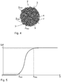
- molding compound particles 2 are provided in a method step S 1 .
- the molding compound particles 2 each comprise metallic and / or glass-like and / or ceramic substrate particles 3 which adhere to one another by means of a two-phase binder 4.
- the two-phase binder 4 in turn comprises an additive 5 in the form of a plasticizer, which is soluble by means of a solvent 6, and a thermoplastic polymer 7, which is insoluble by means of the solvent 6.
- the molding compound particles 2 have a flowability or flowability, which is defined by a Hausner factor H R in accordance with VDI guideline VDI 3405 Part 1 (as of October 2013), where the Hausner factor H R applies: 1 ⁇ H R ⁇ 1.5, in particular 1 ⁇ H R ⁇ 1.4, and in particular 1 ⁇ H R ⁇ 1.3.
- the molding compound particles 2 each have a minimum dimension A min and a maximum dimension A max .
- a min a minimum dimension
- a max a maximum dimension
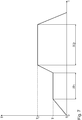
- a volume-related, cumulative distribution Q 3 of the molding compound particles 2 the following applies: 0.005 mm A A max 0,3 0.3 mm, in particular 0.008 mm A A max 0,2 0.2 mm, and in particular 0.01 mm ⁇ A max ⁇ 0.1 mm.
- the volume-related, cumulative distribution Q 3 of the molding compound particles 2 as a function of a dimension A is exemplified in Fig. 5 illustrated.
- the molding compound particles 2 are essentially spherical, so that for at least 80%, in particular for at least 90%, and in particular for at least 95% of a volume-related, cumulative distribution of the molding compound particle 2 applies: 0.6 ⁇ A min / A max ⁇ 1, in particular 0.7 ⁇ A min / A max ⁇ 1, and in particular 0.8 ⁇ A min / A max ⁇ 1.
- the substrate particles 3 each have a proportion of 40 vol.% To 70 vol.%, In particular from 45 vol.% To 65 vol.%, And in particular from 50 vol.% To 60 vol. -%.
- the substrate particles 3 each have a maximum dimension B max , where the following applies for at least 80%, in particular for at least 90%, and in particular for at least 95% of a volume-related, cumulative distribution of the substrate particles 3: 1 ⁇ m B B max 50 50 ⁇ m, in particular 5 ⁇ m ⁇ B max ⁇ 40 ⁇ m, and in particular 10 ⁇ m ⁇ B max ⁇ 30 ⁇ m.
- the substrate particles 3 are held together by the two-phase binder 4 and thus form the powdery molding compound particles 2.
- the binder 4 has a melt viscosity of 10 ° Pa ⁇ s to 10 6 Pa ⁇ s, in particular from 10 ° Pa ⁇ s to 10 5 Pa ⁇ s , and in particular from 10 ° Pa ⁇ s to 10 4 Pa ⁇ s at a temperature which is at least 10 ° C above a temperature T S , the temperature T S with an amorphous structure of the binder 4 the glass transition temperature and with a partially crystalline Binder 4 is the crystallite melting temperature of binder 4.
- the melt viscosity is determined in accordance with DIN EN ISO 3219 (as of October 1994) and in particular for a speed gradient that is selected from the group 1.00 s -1 , 2.50 s -1 , 5.00 s -1 , 10 , 0 s -1 , 25.0 s -1 , 50.0 s -1 and 100 s -1 .
- the stated melt viscosity values apply in particular to a speed gradient of 1.00 s -1 .
- the thermoplastic polymer 7 has a proportion of 10% by weight to 70% by weight, in particular 15% by weight to 50% by weight, and in particular 20% by weight to 40% by weight .-% and the plasticizer 5 a proportion of 30 wt .-% to 90 wt .-%, in particular from 50 wt .-% to 85 wt .-%, and especially from 60% to 80% by weight.
- the binder 4 can optionally contain additional additives.
- the thermoplastic polymer 7 is selected from the group of polycondensates, polymers, polyadducts and thermoplastic elastomers.
- the plasticizer 5 is an ester of an aromatic hydroxybenzoic acid, preferably a p-hydroxybenzoic acid fatty alcohol ester, the length of the carbon chain preferably being in the range C12-C26, in particular in the range C18-C22.
- the plasticizer 5 is used to adjust the melt viscosity or the rheological properties of the binder 4.
- the molding compound particles 2 are produced, for example, in such a way that a suspension of the substrate particles 3 and an alcoholic medium in which the binder 4 is dissolved is subjected to spray drying.
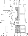
- the molding compound particles 2 are provided by means of a device 8 for additively producing a molded part 9.
- the device 8 has a base body 10 which has a flat surface 11 extending in a horizontal x direction and in a horizontal y direction.
- a supply recess 12 is formed which, together with a base 13 which can be displaced in a vertical z direction, forms a supply space 14 for the molding compound particles 2.
- the storage space 14 is open to the surface 11.
- the molding compound particles 2 are provided in the storage space 14.
- the powdery molding compound particles 2 are also referred to as feedstock powder.
- the x, y and z directions form a Cartesian coordinate system.
- a construction recess 15 is formed in the base body 10 in the x-direction adjacent to the supply recess 12.
- the building recess 15 extends in the x and y directions and defines a construction field.
- a building body 16 which is displaceable in the z direction.
- the building body 16 is preferably designed as a building platform.
- the construction recess 15 and the building body 16 delimit a construction space 17 that is open towards the surface 11.
- a first layer L 1 of molding compound particles 2 is applied to the building body 16 by means of an application device 18.
- the application device 18 is arranged in the z direction above the surface 11 and conveys provided molding material particles 2 into the installation space 17.
- the application device 18 has, for example, a doctor blade 19 which extends in the y direction and in the x direction along the Surface 11 is shiftable.
- the base 13 is first shifted in the z direction, so that a desired amount of the molding compound particles 2 is located above the surface 11.
- the doctor blade 19 is displaced in the x direction, so that the doctor blade 19 takes the molding compound particles 2 located above the surface 11 and conveys it into the installation space 17 and distributes it evenly there.
- the displacement of the floor 13, the doctor blade 19 and the foundation body 16 is controlled by means of a control device 20.
- the first layer L 1 is applied with a thickness D which results from the distance of the building body 16 from the surface 11.
- a method step S 3 the binder 4 of the molding compound particles 2 is selectively melted in the first layer L 1 , so that a first molding layer F 1 is formed.
- the first layer L 1 is closest to the surface 11 and forms a construction area.
- the construction area is heated to a temperature T B by means of heating elements 23.
- T s is the glass transition temperature in the case of an amorphous structure of the binder 4 or the highest crystallite melting temperature of the binder 4 in the case of a partially crystalline or crystalline structure of the binder 4.
- the selective melting takes place by means of electromagnetic radiation R, in particular by means of laser radiation.
- the electromagnetic radiation R is generated by means of an electromagnetic radiation source 21 and directed onto the construction field via a mirror device 22.
- the mirror device 22 enables the electromagnetic radiation R striking the construction field to be displaced in the x and y directions.
- the electromagnetic radiation R is shifted in the x and / or the y direction in accordance with the molded part 9 to be produced.
- the binder 4 is melted by means of the electromagnetic radiation R, so that the binder 4 runs between the substrate particles 3 and forms the solid first molded part layer F 1 during solidification.
- a further layer L 2 of molding compound particles 2 is applied to the previously applied layer L 1 in the manner described.
- the base 13 is shifted in the z direction, so that a desired amount of molding compound particles 2 is located above the surface 11 and can be transported to the installation space 17 by means of the application device 18.
- the building body 16 is lowered by the thickness D in the z-direction, so that the molding compound particles 2 can be distributed uniformly and homogeneously on the previously applied layer L 1 .
- a method step S 5 the binder 4 of the molding compound particles 2 in the layer L 2 is described in the layer L 2 by means of the electromagnetic radiation R Melted selectively, so that a further molding layer F 2 is produced.
- the melted binder 4 runs between the substrate particles 3 and holds them together after the binder 4 has solidified.
- the process steps S 4 and S 5 are repeated until the molded part 9 is produced additively in the desired manner.
- n 3
- one layer or several layers of molding compound particles 2 can first be applied before the binder 4 is melted by means of the electromagnetic radiation R and a solid first molding layer F 1 is formed.
- the molded part 9 is arranged on at least one non-melted layer.
- a method step S 6 the molded part 9 is removed from the non-melted molding compound particles 2 from the installation space 17 and cleaned.
- the molded part 9 is also referred to as a green part.
- the molded part 9 is chemically debindered.
- the molded part 9 is immersed in a container 24 filled with the solvent 6.
- Acetone serves as solvent 6.
- the solvent 6 dissolves the plasticizer 5 from the molded part 9, whereas the thermoplastic polymer 7 is insoluble and remains in the molded part 9. Due to the removal of the plasticizer 5, the molded part 9 is given a microporous structure.
- the solvent 6 has a temperature T L. The following applies to the temperature T L : 20 ° C ⁇ T L ⁇ 100 ° C, in particular 25 ° C ⁇ T L ⁇ 80 ° C, and in particular 30 ° C ⁇ T L ⁇ 60 ° C.
- the molded part 9 is also referred to as a brown part after chemical debinding. After a period of time .DELTA.t 0 , the chemical debinding is ended and the molded part 9 is removed from the solvent 6.
- the time period ⁇ t 0 depends on the component geometry and in particular on the square of the wall thickness of the molded part 9.
- the molded part 9 is thermally debinded after chemical debinding and then sintered in a process step S 9 .
- the thermal debinding and sintering is carried out by means of a heating device under an inert gas atmosphere or in a reducing atmosphere or in a high vacuum.
- the molded part 9 is brought to a first temperature T 1 .
- the following applies to the first temperature T 1 300 ° C. ⁇ T 1 ⁇ 900 ° C., in particular 400 ° C. ⁇ T 1 ⁇ 800 ° C., and in particular 550 ° C. ⁇ T 1 ⁇ 750 ° C.
- the binder 4 that is to say the thermoplastic polymer 7 and any remaining plasticizer 5, is burned out of the molded part 9 at the first temperature T 1 and the binder 4 is thus thermally removed.
- the substrate particles 3 partially form sinter necks, so that the molded part 9 is held together despite the removal of the thermoplastic polymer 7. Due to the microporous structure of the molded part 9, thermal debinding takes place quickly and evenly.
- the thermal removal of the binder 4 takes place during a time period ⁇ t 1 .
- the period of time .DELTA.t 1 is dependent on the component geometry and in particular square of the wall thickness of the component to be produced. 1
- the time period ⁇ t 1 is preferably selected such that at least 95%, in particular at least 99%, and in particular at least 99.9% of the binder 4 are removed.
- the molded part 9 is then brought to a second temperature T 2 in process step S 9 , which is higher than the first temperature T 1 .
- the second temperature T 2 takes place following applies: 600 ° C ⁇ T 2 ⁇ 2400 ° C, in particular 800 ° C ⁇ T 2 ⁇ 2200 ° C, and in particular 1100 ° C ⁇ T 2 ⁇ 2000 ° C.
- the sintering takes place during a time period ⁇ t 2 .
- the time period ⁇ t 2 depends on the component geometry and in particular on the square of the wall thickness of the component 1 to be produced.
- the time period ⁇ t 2 is preferably so long that no relevant change in a porosity of the component 1 can be achieved by subsequent further sintering. Sintering is preferably carried out until the following applies to the porosity P: 0.01 ⁇ P 0,1 0.15, in particular 0.03 P P ⁇ 0.12, in particular 0.05 P P ⁇ 0.09.
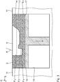
- the component 1 is formed depending on the use of metallic and / or glass-like and / or ceramic substrate particles 3 made of metal and / or glass and / or ceramic.
- the component 1 has closed pores 26 in a component interior 25.
- the component 1 has open pores 28 on a component surface 27.
- the component 1 has a microporous structure, so that at least 80%, in particular at least 85%, and in particular 90% of the pores 26, 28 have a maximum dimension d max between 1 ⁇ m and 100 ⁇ m, in particular between 10 ⁇ m and 80 ⁇ m, and in particular between 20 ⁇ m and 60 ⁇ m.
- the component 1 has a porosity P, which is defined as the quotient of a pore volume to a component volume.
- the component volume includes the material volume and the volumes of the closed pores 26. The following applies to the porosity P: 0.01 P P 0,1 0.15, in particular 0.03 P P 0 0.12, in particular 0.05 P P 0,0 0.09.
- the open pores 28 on the component surface 27 form at least partially undercuts 29.
- the open pores 28 are drop-shaped, so that they expand in the direction of the component interior 25 and form the undercuts 29.
- the component surface 27 has a surface roughness r Z.
- the surface roughness r Z is defined in accordance with DIN EN ISO 4287 (as of October 1998) and measured using the stylus method in accordance with DIN EN ISO 4288 (as of April 1998).
Landscapes
- Engineering & Computer Science (AREA)
- Chemical & Material Sciences (AREA)
- Manufacturing & Machinery (AREA)
- Materials Engineering (AREA)
- Automation & Control Theory (AREA)
- Ceramic Engineering (AREA)
- Structural Engineering (AREA)
- Organic Chemistry (AREA)
- Chemical Kinetics & Catalysis (AREA)
- Inorganic Chemistry (AREA)
- Mechanical Engineering (AREA)
- Civil Engineering (AREA)
- Composite Materials (AREA)
- Powder Metallurgy (AREA)
- Laminated Bodies (AREA)
Priority Applications (2)
| Application Number | Priority Date | Filing Date | Title |
|---|---|---|---|
| EP20177792.7A EP3725433B1 (de) | 2017-04-28 | 2018-03-02 | Verfahren zur additiven herstellung eines bauteils |
| PL18708676T PL3423217T3 (pl) | 2017-04-28 | 2018-03-02 | Sposób przyrostowego wytwarzania elementu konstrukcyjnego |
Applications Claiming Priority (2)
| Application Number | Priority Date | Filing Date | Title |
|---|---|---|---|
| DE102017207210.5A DE102017207210A1 (de) | 2017-04-28 | 2017-04-28 | Verfahren zur additiven Herstellung eines Bauteils sowie additiv hergestelltes Bauteil |
| PCT/EP2018/055152 WO2018197082A1 (de) | 2017-04-28 | 2018-03-02 | Verfahren zur additiven herstellung eines bauteils sowie additiv hergestelltes bauteil |
Related Child Applications (2)
| Application Number | Title | Priority Date | Filing Date |
|---|---|---|---|
| EP20177792.7A Division EP3725433B1 (de) | 2017-04-28 | 2018-03-02 | Verfahren zur additiven herstellung eines bauteils |
| EP20177792.7A Division-Into EP3725433B1 (de) | 2017-04-28 | 2018-03-02 | Verfahren zur additiven herstellung eines bauteils |
Publications (2)
| Publication Number | Publication Date |
|---|---|
| EP3423217A1 EP3423217A1 (de) | 2019-01-09 |
| EP3423217B1 true EP3423217B1 (de) | 2020-08-05 |
Family
ID=61563399
Family Applications (2)
| Application Number | Title | Priority Date | Filing Date |
|---|---|---|---|
| EP18708676.4A Active EP3423217B1 (de) | 2017-04-28 | 2018-03-02 | Verfahren zur additiven herstellung eines bauteils |
| EP20177792.7A Active EP3725433B1 (de) | 2017-04-28 | 2018-03-02 | Verfahren zur additiven herstellung eines bauteils |
Family Applications After (1)
| Application Number | Title | Priority Date | Filing Date |
|---|---|---|---|
| EP20177792.7A Active EP3725433B1 (de) | 2017-04-28 | 2018-03-02 | Verfahren zur additiven herstellung eines bauteils |
Country Status (8)
| Country | Link |
|---|---|
| US (1) | US11858038B2 (pl) |
| EP (2) | EP3423217B1 (pl) |
| KR (1) | KR102467165B1 (pl) |
| CN (1) | CN110573273B (pl) |
| DE (1) | DE102017207210A1 (pl) |
| ES (1) | ES2820294T3 (pl) |
| PL (1) | PL3423217T3 (pl) |
| WO (1) | WO2018197082A1 (pl) |
Families Citing this family (10)
| Publication number | Priority date | Publication date | Assignee | Title |
|---|---|---|---|---|
| DE102017207210A1 (de) | 2017-04-28 | 2018-10-31 | Skz-Kfe Ggmbh | Verfahren zur additiven Herstellung eines Bauteils sowie additiv hergestelltes Bauteil |
| FR3095365B1 (fr) * | 2019-04-25 | 2023-03-31 | Safran | Support et systeme pour fabrication additive et procede de fabrication additive mettant en œuvre un tel support |
| US20230226608A1 (en) * | 2020-05-14 | 2023-07-20 | Jan Franck | Method and apparatus for the additive manufacturing of a workpiece |
| CN117897247A (zh) | 2021-08-19 | 2024-04-16 | 海德梅德材料有限公司 | 用于粉末床增材制造方法的颗粒原料配混物以及成型和烧结方法 |
| CA3228949A1 (en) | 2021-08-19 | 2023-02-23 | Headmade Materials Gmbh | Binder component for a feedstock compound for use in a shaping and sintering process, particulate feedstock compound, and shaping and sintering process |
| US20250065398A1 (en) | 2021-08-19 | 2025-02-27 | Headmade Materials Gmbh | Particulate feedstock compound for use in a powder bed additive manufacturing process, and shaping and sintering process |
| WO2023021202A1 (en) | 2021-08-19 | 2023-02-23 | Headmade Materials Gmbh | Processes for producing a sintered part |
| AT525693B1 (de) | 2021-11-18 | 2023-08-15 | Miba Sinter Austria Gmbh | Verfahren zur Herstellung eines Bauteils |
| WO2023111037A1 (en) | 2021-12-14 | 2023-06-22 | Headmade Materials Gmbh | Process for the manufacture of an element having porous portions and sintered element having non-uniform porosity |
| EP4554744A1 (en) | 2022-08-19 | 2025-05-21 | Headmade Materials GmbH | Particulate feedstock compound for use in a shaping and sintering process, and shaping and sintering process |
Citations (1)
| Publication number | Priority date | Publication date | Assignee | Title |
|---|---|---|---|---|
| US6110411A (en) * | 1997-03-18 | 2000-08-29 | Clausen; Christian Henning | Laser sinterable thermoplastic powder |
Family Cites Families (19)
| Publication number | Priority date | Publication date | Assignee | Title |
|---|---|---|---|---|
| WO1992000182A1 (en) | 1990-06-29 | 1992-01-09 | Flexline Services Ltd. | A process for manufacturing reinforced composites and filament material for use in said process |
| WO1995030503A1 (en) * | 1994-05-06 | 1995-11-16 | Dtm Corporation | Binder compositions for selective laser sintering processes |
| US5745834A (en) * | 1995-09-19 | 1998-04-28 | Rockwell International Corporation | Free form fabrication of metallic components |
| US5749041A (en) | 1995-10-13 | 1998-05-05 | Dtm Corporation | Method of forming three-dimensional articles using thermosetting materials |
| AR007698A1 (es) | 1996-08-28 | 1999-11-10 | Deere & Co | Metodo para aportar dureza superficial a una superficie metalica y un lodo preparado por dicho metodo |
| US6814926B2 (en) * | 2003-03-19 | 2004-11-09 | 3D Systems Inc. | Metal powder composition for laser sintering |
| US7713896B2 (en) * | 2004-04-14 | 2010-05-11 | Robert Bosch Gmbh | Method for producing ceramic green compacts for ceramic components |
| DE102005033625B4 (de) * | 2005-07-19 | 2010-06-10 | Mtu Aero Engines Gmbh | Verfahren zur Herstellung und /oder Reparatur eines integral beschaufelten Rotors |
| GB0613491D0 (en) | 2006-07-06 | 2006-08-16 | Avx Ltd | Binder removal particulate bodies |
| JP5439861B2 (ja) | 2008-02-29 | 2014-03-12 | 戸田工業株式会社 | 強磁性金属粒子粉末及びその製造法、並びに磁気記録媒体 |
| US9969930B2 (en) | 2013-08-15 | 2018-05-15 | Halliburton Energy Services, Inc. | Additive fabrication of proppants |
| KR20160058719A (ko) | 2013-10-14 | 2016-05-25 | 월풀 에쎄.아. | 다공성 부재 및 다공성 성분의 제조방법 |
| CN106457404B (zh) | 2014-04-23 | 2020-02-21 | 阿尔法金属公司 | 用于制造金属粉末的方法 |
| CN105451916B (zh) * | 2014-05-13 | 2018-12-18 | 犹他大学研究基金会 | 基本为球形的金属粉末的制备 |
| ES2753248T3 (es) * | 2014-07-08 | 2020-04-07 | Emery Oleochemicals Gmbh | Materia prima sinterizable para el uso en dispositivos de impresión 3D |
| US10272492B2 (en) * | 2016-04-14 | 2019-04-30 | Desktop Metal, Inc. | Multi-part removable support structures |
| CN105970140B (zh) | 2016-06-22 | 2019-04-30 | 广东正德材料表面科技有限公司 | 一种纳米复合结构喂料及其制备方法 |
| CN106334792A (zh) * | 2016-11-02 | 2017-01-18 | 青岛科技大学 | 一种用于金属低温3d打印材料的制备及其打印成型方法 |
| DE102017207210A1 (de) | 2017-04-28 | 2018-10-31 | Skz-Kfe Ggmbh | Verfahren zur additiven Herstellung eines Bauteils sowie additiv hergestelltes Bauteil |
-
2017
- 2017-04-28 DE DE102017207210.5A patent/DE102017207210A1/de not_active Withdrawn
-
2018
- 2018-03-02 KR KR1020197031859A patent/KR102467165B1/ko active Active
- 2018-03-02 CN CN201880027036.5A patent/CN110573273B/zh active Active
- 2018-03-02 ES ES18708676T patent/ES2820294T3/es active Active
- 2018-03-02 WO PCT/EP2018/055152 patent/WO2018197082A1/de not_active Ceased
- 2018-03-02 US US16/608,762 patent/US11858038B2/en active Active
- 2018-03-02 EP EP18708676.4A patent/EP3423217B1/de active Active
- 2018-03-02 PL PL18708676T patent/PL3423217T3/pl unknown
- 2018-03-02 EP EP20177792.7A patent/EP3725433B1/de active Active
Patent Citations (1)
| Publication number | Priority date | Publication date | Assignee | Title |
|---|---|---|---|---|
| US6110411A (en) * | 1997-03-18 | 2000-08-29 | Clausen; Christian Henning | Laser sinterable thermoplastic powder |
Non-Patent Citations (1)
| Title |
|---|
| SUBRAMANIAN K ET AL: "SELECTIVE LASER SINTERING OF ALUMINA WITH POLYMER BINDERS", RAPID PROTOTYPING JOURNAL, MCB UNIVERSITY PRESS, BRADFORD, GB, vol. 1, no. 2, 1 January 1995 (1995-01-01), pages 24 - 35, XP001155553, ISSN: 1355-2546, DOI: 10.1108/13552549510086844 * |
Also Published As
| Publication number | Publication date |
|---|---|
| EP3423217A1 (de) | 2019-01-09 |
| ES2820294T3 (es) | 2021-04-20 |
| EP3725433C0 (de) | 2023-06-07 |
| PL3423217T3 (pl) | 2021-01-11 |
| KR20200002863A (ko) | 2020-01-08 |
| DE102017207210A1 (de) | 2018-10-31 |
| KR102467165B1 (ko) | 2022-11-15 |
| CN110573273B (zh) | 2022-07-08 |
| EP3725433B1 (de) | 2023-06-07 |
| US20200198006A1 (en) | 2020-06-25 |
| CN110573273A (zh) | 2019-12-13 |
| US11858038B2 (en) | 2024-01-02 |
| WO2018197082A1 (de) | 2018-11-01 |
| EP3725433A1 (de) | 2020-10-21 |
Similar Documents
| Publication | Publication Date | Title |
|---|---|---|
| EP3423217B1 (de) | Verfahren zur additiven herstellung eines bauteils | |
| EP3074208B1 (de) | 3d-druckverfahren mit schlicker | |
| EP2794152B1 (de) | Verfahren zur fertigung eines kompakten bauteils sowie mit dem verfahren herstellbares bauteil | |
| EP2468436B1 (de) | Verfahren zur Herstellung von Metallformkörpern mit strukturierter Oberfläche | |
| EP3395476B1 (de) | Verfahren zur herstellung eines thermoplastischen formmassenpulvers | |
| WO2018206250A1 (de) | Additive fertigung von metallmatrix-verbundwerkstoffen | |
| DE102011013894A1 (de) | Verfahren zur endformnahen Herstellung von Bauteilen | |
| WO2014019954A1 (de) | Mehrkomponenten-fügen von plastischen zubereitungen zur herstellung von medizinprodukten mit funktioneller oberfläche | |
| EP3145662B1 (de) | Verfahren zur herstellung keramischer und/oder metallischer bauteile | |
| DE102018129162A1 (de) | Verfahren zum Herstellen eines Bauteils aus Metall oder Werkstoffen der technischen Keramik | |
| DE3736660C2 (pl) | ||
| EP3427866A2 (de) | Verfahren zur herstellung eines kriechbeständigen werkstoffs | |
| WO2014044433A1 (de) | Herstellen eines refraktärmetall-bauteils | |
| WO1989003736A1 (fr) | Outil heteroporeux de formage de moules de fonte en sable de moulage et son procede de fabrication | |
| DE19809657B4 (de) | Verfahren zur Herstellung eines Keramikbauteils | |
| EP3173227A1 (de) | Freiform-keramikbauteile | |
| EP2739417B1 (de) | Bindemittelmischung für die herstellung von formteilen mittels spritzverfahren | |
| EP3173392B1 (de) | Verfahren zur herstellung von keramikteilen | |
| AT403692B (de) | Verfahren zur herstellung von keramischen formkörpern | |
| EP2970013B1 (de) | Verfahren zur herstellung eines formkörpers | |
| DE102018116642A1 (de) | Offenzelliges Keramiknetzwerk und Verfahren zu seiner Herstellung | |
| DE19508959C2 (de) | Formkörper aus keramischem, pulvermetallurgischem oder Verbundwerkstoff und Verfahren zu seiner Herstellung | |
| WO2018077340A1 (de) | Verfahren und anlage zum herstellen eines reibbelags aus sintermetall | |
| DE102023208014A1 (de) | Verfahren zur Herstellung von gesinterten metallischen und/oder keramischen Bauteilen sowie mit dem Verfahren hergestellte Bauteile |
Legal Events
| Date | Code | Title | Description |
|---|---|---|---|
| STAA | Information on the status of an ep patent application or granted ep patent |
Free format text: STATUS: UNKNOWN |
|
| STAA | Information on the status of an ep patent application or granted ep patent |
Free format text: STATUS: THE INTERNATIONAL PUBLICATION HAS BEEN MADE |
|
| PUAI | Public reference made under article 153(3) epc to a published international application that has entered the european phase |
Free format text: ORIGINAL CODE: 0009012 |
|
| STAA | Information on the status of an ep patent application or granted ep patent |
Free format text: STATUS: REQUEST FOR EXAMINATION WAS MADE |
|
| 17P | Request for examination filed |
Effective date: 20181002 |
|
| AK | Designated contracting states |
Kind code of ref document: A1 Designated state(s): AL AT BE BG CH CY CZ DE DK EE ES FI FR GB GR HR HU IE IS IT LI LT LU LV MC MK MT NL NO PL PT RO RS SE SI SK SM TR |
|
| AX | Request for extension of the european patent |
Extension state: BA ME |
|
| STAA | Information on the status of an ep patent application or granted ep patent |
Free format text: STATUS: EXAMINATION IS IN PROGRESS |
|
| 17Q | First examination report despatched |
Effective date: 20190523 |
|
| RAP1 | Party data changed (applicant data changed or rights of an application transferred) |
Owner name: SKZ-KFE GGMBH |
|
| GRAP | Despatch of communication of intention to grant a patent |
Free format text: ORIGINAL CODE: EPIDOSNIGR1 |
|
| STAA | Information on the status of an ep patent application or granted ep patent |
Free format text: STATUS: GRANT OF PATENT IS INTENDED |
|
| INTG | Intention to grant announced |
Effective date: 20200107 |
|
| GRAJ | Information related to disapproval of communication of intention to grant by the applicant or resumption of examination proceedings by the epo deleted |
Free format text: ORIGINAL CODE: EPIDOSDIGR1 |
|
| STAA | Information on the status of an ep patent application or granted ep patent |
Free format text: STATUS: EXAMINATION IS IN PROGRESS |
|
| GRAP | Despatch of communication of intention to grant a patent |
Free format text: ORIGINAL CODE: EPIDOSNIGR1 |
|
| STAA | Information on the status of an ep patent application or granted ep patent |
Free format text: STATUS: GRANT OF PATENT IS INTENDED |
|
| INTC | Intention to grant announced (deleted) | ||
| INTG | Intention to grant announced |
Effective date: 20200212 |
|
| GRAS | Grant fee paid |
Free format text: ORIGINAL CODE: EPIDOSNIGR3 |
|
| GRAA | (expected) grant |
Free format text: ORIGINAL CODE: 0009210 |
|
| STAA | Information on the status of an ep patent application or granted ep patent |
Free format text: STATUS: THE PATENT HAS BEEN GRANTED |
|
| AK | Designated contracting states |
Kind code of ref document: B1 Designated state(s): AL AT BE BG CH CY CZ DE DK EE ES FI FR GB GR HR HU IE IS IT LI LT LU LV MC MK MT NL NO PL PT RO RS SE SI SK SM TR |
|
| DAV | Request for validation of the european patent (deleted) | ||
| DAX | Request for extension of the european patent (deleted) | ||
| REG | Reference to a national code |
Ref country code: GB Ref legal event code: FG4D Free format text: NOT ENGLISH |
|
| REG | Reference to a national code |
Ref country code: CH Ref legal event code: EP |
|
| REG | Reference to a national code |
Ref country code: AT Ref legal event code: REF Ref document number: 1298002 Country of ref document: AT Kind code of ref document: T Effective date: 20200815 |
|
| REG | Reference to a national code |
Ref country code: DE Ref legal event code: R096 Ref document number: 502018002123 Country of ref document: DE |
|
| REG | Reference to a national code |
Ref country code: IE Ref legal event code: FG4D Free format text: LANGUAGE OF EP DOCUMENT: GERMAN |
|
| REG | Reference to a national code |
Ref country code: SE Ref legal event code: TRGR |
|
| REG | Reference to a national code |
Ref country code: DK Ref legal event code: T3 Effective date: 20200929 |
|
| REG | Reference to a national code |
Ref country code: NL Ref legal event code: FP |
|
| REG | Reference to a national code |
Ref country code: LT Ref legal event code: MG4D |
|
| PG25 | Lapsed in a contracting state [announced via postgrant information from national office to epo] |
Ref country code: FI Free format text: LAPSE BECAUSE OF FAILURE TO SUBMIT A TRANSLATION OF THE DESCRIPTION OR TO PAY THE FEE WITHIN THE PRESCRIBED TIME-LIMIT Effective date: 20200805 Ref country code: NO Free format text: LAPSE BECAUSE OF FAILURE TO SUBMIT A TRANSLATION OF THE DESCRIPTION OR TO PAY THE FEE WITHIN THE PRESCRIBED TIME-LIMIT Effective date: 20201105 Ref country code: GR Free format text: LAPSE BECAUSE OF FAILURE TO SUBMIT A TRANSLATION OF THE DESCRIPTION OR TO PAY THE FEE WITHIN THE PRESCRIBED TIME-LIMIT Effective date: 20201106 Ref country code: LT Free format text: LAPSE BECAUSE OF FAILURE TO SUBMIT A TRANSLATION OF THE DESCRIPTION OR TO PAY THE FEE WITHIN THE PRESCRIBED TIME-LIMIT Effective date: 20200805 Ref country code: BG Free format text: LAPSE BECAUSE OF FAILURE TO SUBMIT A TRANSLATION OF THE DESCRIPTION OR TO PAY THE FEE WITHIN THE PRESCRIBED TIME-LIMIT Effective date: 20201105 Ref country code: PT Free format text: LAPSE BECAUSE OF FAILURE TO SUBMIT A TRANSLATION OF THE DESCRIPTION OR TO PAY THE FEE WITHIN THE PRESCRIBED TIME-LIMIT Effective date: 20201207 Ref country code: HR Free format text: LAPSE BECAUSE OF FAILURE TO SUBMIT A TRANSLATION OF THE DESCRIPTION OR TO PAY THE FEE WITHIN THE PRESCRIBED TIME-LIMIT Effective date: 20200805 |
|
| PG25 | Lapsed in a contracting state [announced via postgrant information from national office to epo] |
Ref country code: LV Free format text: LAPSE BECAUSE OF FAILURE TO SUBMIT A TRANSLATION OF THE DESCRIPTION OR TO PAY THE FEE WITHIN THE PRESCRIBED TIME-LIMIT Effective date: 20200805 Ref country code: RS Free format text: LAPSE BECAUSE OF FAILURE TO SUBMIT A TRANSLATION OF THE DESCRIPTION OR TO PAY THE FEE WITHIN THE PRESCRIBED TIME-LIMIT Effective date: 20200805 Ref country code: IS Free format text: LAPSE BECAUSE OF FAILURE TO SUBMIT A TRANSLATION OF THE DESCRIPTION OR TO PAY THE FEE WITHIN THE PRESCRIBED TIME-LIMIT Effective date: 20201205 |
|
| REG | Reference to a national code |
Ref country code: ES Ref legal event code: FG2A Ref document number: 2820294 Country of ref document: ES Kind code of ref document: T3 Effective date: 20210420 |
|
| PG25 | Lapsed in a contracting state [announced via postgrant information from national office to epo] |
Ref country code: EE Free format text: LAPSE BECAUSE OF FAILURE TO SUBMIT A TRANSLATION OF THE DESCRIPTION OR TO PAY THE FEE WITHIN THE PRESCRIBED TIME-LIMIT Effective date: 20200805 Ref country code: RO Free format text: LAPSE BECAUSE OF FAILURE TO SUBMIT A TRANSLATION OF THE DESCRIPTION OR TO PAY THE FEE WITHIN THE PRESCRIBED TIME-LIMIT Effective date: 20200805 Ref country code: SM Free format text: LAPSE BECAUSE OF FAILURE TO SUBMIT A TRANSLATION OF THE DESCRIPTION OR TO PAY THE FEE WITHIN THE PRESCRIBED TIME-LIMIT Effective date: 20200805 |
|
| REG | Reference to a national code |
Ref country code: DE Ref legal event code: R097 Ref document number: 502018002123 Country of ref document: DE |
|
| PG25 | Lapsed in a contracting state [announced via postgrant information from national office to epo] |
Ref country code: AL Free format text: LAPSE BECAUSE OF FAILURE TO SUBMIT A TRANSLATION OF THE DESCRIPTION OR TO PAY THE FEE WITHIN THE PRESCRIBED TIME-LIMIT Effective date: 20200805 |
|
| PLBE | No opposition filed within time limit |
Free format text: ORIGINAL CODE: 0009261 |
|
| STAA | Information on the status of an ep patent application or granted ep patent |
Free format text: STATUS: NO OPPOSITION FILED WITHIN TIME LIMIT |
|
| PG25 | Lapsed in a contracting state [announced via postgrant information from national office to epo] |
Ref country code: SK Free format text: LAPSE BECAUSE OF FAILURE TO SUBMIT A TRANSLATION OF THE DESCRIPTION OR TO PAY THE FEE WITHIN THE PRESCRIBED TIME-LIMIT Effective date: 20200805 |
|
| 26N | No opposition filed |
Effective date: 20210507 |
|
| PG25 | Lapsed in a contracting state [announced via postgrant information from national office to epo] |
Ref country code: SI Free format text: LAPSE BECAUSE OF FAILURE TO SUBMIT A TRANSLATION OF THE DESCRIPTION OR TO PAY THE FEE WITHIN THE PRESCRIBED TIME-LIMIT Effective date: 20200805 |
|
| PGFP | Annual fee paid to national office [announced via postgrant information from national office to epo] |
Ref country code: MC Payment date: 20230320 Year of fee payment: 6 Ref country code: LU Payment date: 20230320 Year of fee payment: 6 Ref country code: IE Payment date: 20230320 Year of fee payment: 6 Ref country code: FR Payment date: 20230321 Year of fee payment: 6 Ref country code: DK Payment date: 20230323 Year of fee payment: 6 Ref country code: AT Payment date: 20230208 Year of fee payment: 6 |
|
| PGFP | Annual fee paid to national office [announced via postgrant information from national office to epo] |
Ref country code: SE Payment date: 20230315 Year of fee payment: 6 Ref country code: GB Payment date: 20230323 Year of fee payment: 6 Ref country code: BE Payment date: 20230321 Year of fee payment: 6 |
|
| P01 | Opt-out of the competence of the unified patent court (upc) registered |
Effective date: 20230505 |
|
| PG25 | Lapsed in a contracting state [announced via postgrant information from national office to epo] |
Ref country code: CY Free format text: LAPSE BECAUSE OF FAILURE TO SUBMIT A TRANSLATION OF THE DESCRIPTION OR TO PAY THE FEE WITHIN THE PRESCRIBED TIME-LIMIT Effective date: 20200805 |
|
| PGFP | Annual fee paid to national office [announced via postgrant information from national office to epo] |
Ref country code: NL Payment date: 20230322 Year of fee payment: 6 |
|
| PG25 | Lapsed in a contracting state [announced via postgrant information from national office to epo] |
Ref country code: HU Free format text: LAPSE BECAUSE OF FAILURE TO SUBMIT A TRANSLATION OF THE DESCRIPTION OR TO PAY THE FEE WITHIN THE PRESCRIBED TIME-LIMIT; INVALID AB INITIO Effective date: 20180302 |
|
| PGFP | Annual fee paid to national office [announced via postgrant information from national office to epo] |
Ref country code: IT Payment date: 20230331 Year of fee payment: 6 |
|
| PG25 | Lapsed in a contracting state [announced via postgrant information from national office to epo] |
Ref country code: MK Free format text: LAPSE BECAUSE OF FAILURE TO SUBMIT A TRANSLATION OF THE DESCRIPTION OR TO PAY THE FEE WITHIN THE PRESCRIBED TIME-LIMIT Effective date: 20200805 |
|
| PG25 | Lapsed in a contracting state [announced via postgrant information from national office to epo] |
Ref country code: MT Free format text: LAPSE BECAUSE OF FAILURE TO SUBMIT A TRANSLATION OF THE DESCRIPTION OR TO PAY THE FEE WITHIN THE PRESCRIBED TIME-LIMIT Effective date: 20200805 |
|
| REG | Reference to a national code |
Ref country code: DK Ref legal event code: EBP Effective date: 20240331 |
|
| REG | Reference to a national code |
Ref country code: SE Ref legal event code: EUG |
|
| REG | Reference to a national code |
Ref country code: NL Ref legal event code: MM Effective date: 20240401 |
|
| REG | Reference to a national code |
Ref country code: AT Ref legal event code: MM01 Ref document number: 1298002 Country of ref document: AT Kind code of ref document: T Effective date: 20240302 |
|
| PG25 | Lapsed in a contracting state [announced via postgrant information from national office to epo] |
Ref country code: LU Free format text: LAPSE BECAUSE OF NON-PAYMENT OF DUE FEES Effective date: 20240302 |
|
| PG25 | Lapsed in a contracting state [announced via postgrant information from national office to epo] |
Ref country code: MC Free format text: LAPSE BECAUSE OF NON-PAYMENT OF DUE FEES Effective date: 20240402 |
|
| GBPC | Gb: european patent ceased through non-payment of renewal fee |
Effective date: 20240302 |
|
| PG25 | Lapsed in a contracting state [announced via postgrant information from national office to epo] |
Ref country code: MC Free format text: LAPSE BECAUSE OF NON-PAYMENT OF DUE FEES Effective date: 20240402 Ref country code: LU Free format text: LAPSE BECAUSE OF NON-PAYMENT OF DUE FEES Effective date: 20240302 |
|
| PG25 | Lapsed in a contracting state [announced via postgrant information from national office to epo] |
Ref country code: NL Free format text: LAPSE BECAUSE OF NON-PAYMENT OF DUE FEES Effective date: 20240401 |
|
| REG | Reference to a national code |
Ref country code: BE Ref legal event code: MM Effective date: 20240331 |
|
| PG25 | Lapsed in a contracting state [announced via postgrant information from national office to epo] |
Ref country code: NL Free format text: LAPSE BECAUSE OF NON-PAYMENT OF DUE FEES Effective date: 20240401 |
|
| PG25 | Lapsed in a contracting state [announced via postgrant information from national office to epo] |
Ref country code: BE Free format text: LAPSE BECAUSE OF NON-PAYMENT OF DUE FEES Effective date: 20240331 |
|
| PG25 | Lapsed in a contracting state [announced via postgrant information from national office to epo] |
Ref country code: GB Free format text: LAPSE BECAUSE OF NON-PAYMENT OF DUE FEES Effective date: 20240302 |
|
| PG25 | Lapsed in a contracting state [announced via postgrant information from national office to epo] |
Ref country code: FR Free format text: LAPSE BECAUSE OF NON-PAYMENT OF DUE FEES Effective date: 20240331 |
|
| PG25 | Lapsed in a contracting state [announced via postgrant information from national office to epo] |
Ref country code: AT Free format text: LAPSE BECAUSE OF NON-PAYMENT OF DUE FEES Effective date: 20240302 |
|
| PG25 | Lapsed in a contracting state [announced via postgrant information from national office to epo] |
Ref country code: IE Free format text: LAPSE BECAUSE OF NON-PAYMENT OF DUE FEES Effective date: 20240302 |
|
| PG25 | Lapsed in a contracting state [announced via postgrant information from national office to epo] |
Ref country code: IE Free format text: LAPSE BECAUSE OF NON-PAYMENT OF DUE FEES Effective date: 20240302 Ref country code: GB Free format text: LAPSE BECAUSE OF NON-PAYMENT OF DUE FEES Effective date: 20240302 Ref country code: FR Free format text: LAPSE BECAUSE OF NON-PAYMENT OF DUE FEES Effective date: 20240331 Ref country code: BE Free format text: LAPSE BECAUSE OF NON-PAYMENT OF DUE FEES Effective date: 20240331 Ref country code: AT Free format text: LAPSE BECAUSE OF NON-PAYMENT OF DUE FEES Effective date: 20240302 |
|
| PG25 | Lapsed in a contracting state [announced via postgrant information from national office to epo] |
Ref country code: DK Free format text: LAPSE BECAUSE OF NON-PAYMENT OF DUE FEES Effective date: 20240331 |
|
| PGFP | Annual fee paid to national office [announced via postgrant information from national office to epo] |
Ref country code: PL Payment date: 20250218 Year of fee payment: 8 Ref country code: CZ Payment date: 20250218 Year of fee payment: 8 |
|
| PG25 | Lapsed in a contracting state [announced via postgrant information from national office to epo] |
Ref country code: IT Free format text: LAPSE BECAUSE OF NON-PAYMENT OF DUE FEES Effective date: 20240302 |
|
| PGFP | Annual fee paid to national office [announced via postgrant information from national office to epo] |
Ref country code: TR Payment date: 20250221 Year of fee payment: 8 |
|
| PGFP | Annual fee paid to national office [announced via postgrant information from national office to epo] |
Ref country code: DE Payment date: 20250520 Year of fee payment: 8 |
|
| PGFP | Annual fee paid to national office [announced via postgrant information from national office to epo] |
Ref country code: ES Payment date: 20250416 Year of fee payment: 8 |
|
| PGFP | Annual fee paid to national office [announced via postgrant information from national office to epo] |
Ref country code: CH Payment date: 20250401 Year of fee payment: 8 |
|
| PG25 | Lapsed in a contracting state [announced via postgrant information from national office to epo] |
Ref country code: SE Free format text: LAPSE BECAUSE OF NON-PAYMENT OF DUE FEES Effective date: 20240303 |