EP3421897B1 - Système de climatisation - Google Patents
Système de climatisation Download PDFInfo
- Publication number
- EP3421897B1 EP3421897B1 EP16891621.1A EP16891621A EP3421897B1 EP 3421897 B1 EP3421897 B1 EP 3421897B1 EP 16891621 A EP16891621 A EP 16891621A EP 3421897 B1 EP3421897 B1 EP 3421897B1
- Authority
- EP
- European Patent Office
- Prior art keywords
- air
- load
- conditioning
- unit
- lower limit
- Prior art date
- Legal status (The legal status is an assumption and is not a legal conclusion. Google has not performed a legal analysis and makes no representation as to the accuracy of the status listed.)
- Active
Links
- 238000004378 air conditioning Methods 0.000 title claims description 250
- 238000012545 processing Methods 0.000 claims description 74
- 238000000605 extraction Methods 0.000 claims description 21
- 238000004364 calculation method Methods 0.000 claims description 18
- 239000003507 refrigerant Substances 0.000 description 81
- XLYOFNOQVPJJNP-UHFFFAOYSA-N water Substances O XLYOFNOQVPJJNP-UHFFFAOYSA-N 0.000 description 34
- 238000001816 cooling Methods 0.000 description 23
- 238000010438 heat treatment Methods 0.000 description 22
- 238000010586 diagram Methods 0.000 description 16
- 239000007788 liquid Substances 0.000 description 12
- 238000000034 method Methods 0.000 description 10
- 230000006870 function Effects 0.000 description 7
- 230000005855 radiation Effects 0.000 description 5
- 230000005540 biological transmission Effects 0.000 description 3
- 230000007812 deficiency Effects 0.000 description 3
- 238000005259 measurement Methods 0.000 description 3
- 238000012937 correction Methods 0.000 description 2
- 230000007423 decrease Effects 0.000 description 2
- 238000012360 testing method Methods 0.000 description 2
- 238000013459 approach Methods 0.000 description 1
- 238000013528 artificial neural network Methods 0.000 description 1
- 239000012267 brine Substances 0.000 description 1
- 230000001143 conditioned effect Effects 0.000 description 1
- 238000013461 design Methods 0.000 description 1
- 230000000694 effects Effects 0.000 description 1
- 230000007613 environmental effect Effects 0.000 description 1
- 239000000284 extract Substances 0.000 description 1
- 239000011521 glass Substances 0.000 description 1
- 230000004044 response Effects 0.000 description 1
- 238000005070 sampling Methods 0.000 description 1
- HPALAKNZSZLMCH-UHFFFAOYSA-M sodium;chloride;hydrate Chemical compound O.[Na+].[Cl-] HPALAKNZSZLMCH-UHFFFAOYSA-M 0.000 description 1
- 239000000243 solution Substances 0.000 description 1
Images


Classifications
-
- F—MECHANICAL ENGINEERING; LIGHTING; HEATING; WEAPONS; BLASTING
- F24—HEATING; RANGES; VENTILATING
- F24F—AIR-CONDITIONING; AIR-HUMIDIFICATION; VENTILATION; USE OF AIR CURRENTS FOR SCREENING
- F24F11/00—Control or safety arrangements
- F24F11/30—Control or safety arrangements for purposes related to the operation of the system, e.g. for safety or monitoring
- F24F11/46—Improving electric energy efficiency or saving
-
- F—MECHANICAL ENGINEERING; LIGHTING; HEATING; WEAPONS; BLASTING
- F24—HEATING; RANGES; VENTILATING
- F24F—AIR-CONDITIONING; AIR-HUMIDIFICATION; VENTILATION; USE OF AIR CURRENTS FOR SCREENING
- F24F11/00—Control or safety arrangements
- F24F11/50—Control or safety arrangements characterised by user interfaces or communication
- F24F11/52—Indication arrangements, e.g. displays
-
- F—MECHANICAL ENGINEERING; LIGHTING; HEATING; WEAPONS; BLASTING
- F24—HEATING; RANGES; VENTILATING
- F24F—AIR-CONDITIONING; AIR-HUMIDIFICATION; VENTILATION; USE OF AIR CURRENTS FOR SCREENING
- F24F11/00—Control or safety arrangements
- F24F11/50—Control or safety arrangements characterised by user interfaces or communication
- F24F11/54—Control or safety arrangements characterised by user interfaces or communication using one central controller connected to several sub-controllers
-
- F—MECHANICAL ENGINEERING; LIGHTING; HEATING; WEAPONS; BLASTING
- F24—HEATING; RANGES; VENTILATING
- F24F—AIR-CONDITIONING; AIR-HUMIDIFICATION; VENTILATION; USE OF AIR CURRENTS FOR SCREENING
- F24F11/00—Control or safety arrangements
- F24F11/50—Control or safety arrangements characterised by user interfaces or communication
- F24F11/56—Remote control
-
- F—MECHANICAL ENGINEERING; LIGHTING; HEATING; WEAPONS; BLASTING
- F24—HEATING; RANGES; VENTILATING
- F24F—AIR-CONDITIONING; AIR-HUMIDIFICATION; VENTILATION; USE OF AIR CURRENTS FOR SCREENING
- F24F11/00—Control or safety arrangements
- F24F11/62—Control or safety arrangements characterised by the type of control or by internal processing, e.g. using fuzzy logic, adaptive control or estimation of values
- F24F11/63—Electronic processing
- F24F11/64—Electronic processing using pre-stored data
-
- F—MECHANICAL ENGINEERING; LIGHTING; HEATING; WEAPONS; BLASTING
- F24—HEATING; RANGES; VENTILATING
- F24F—AIR-CONDITIONING; AIR-HUMIDIFICATION; VENTILATION; USE OF AIR CURRENTS FOR SCREENING
- F24F11/00—Control or safety arrangements
- F24F11/62—Control or safety arrangements characterised by the type of control or by internal processing, e.g. using fuzzy logic, adaptive control or estimation of values
- F24F11/63—Electronic processing
- F24F11/65—Electronic processing for selecting an operating mode
-
- F—MECHANICAL ENGINEERING; LIGHTING; HEATING; WEAPONS; BLASTING
- F24—HEATING; RANGES; VENTILATING
- F24F—AIR-CONDITIONING; AIR-HUMIDIFICATION; VENTILATION; USE OF AIR CURRENTS FOR SCREENING
- F24F11/00—Control or safety arrangements
- F24F11/89—Arrangement or mounting of control or safety devices
-
- G—PHYSICS
- G05—CONTROLLING; REGULATING
- G05B—CONTROL OR REGULATING SYSTEMS IN GENERAL; FUNCTIONAL ELEMENTS OF SUCH SYSTEMS; MONITORING OR TESTING ARRANGEMENTS FOR SUCH SYSTEMS OR ELEMENTS
- G05B13/00—Adaptive control systems, i.e. systems automatically adjusting themselves to have a performance which is optimum according to some preassigned criterion
- G05B13/02—Adaptive control systems, i.e. systems automatically adjusting themselves to have a performance which is optimum according to some preassigned criterion electric
- G05B13/04—Adaptive control systems, i.e. systems automatically adjusting themselves to have a performance which is optimum according to some preassigned criterion electric involving the use of models or simulators
- G05B13/048—Adaptive control systems, i.e. systems automatically adjusting themselves to have a performance which is optimum according to some preassigned criterion electric involving the use of models or simulators using a predictor
-
- F—MECHANICAL ENGINEERING; LIGHTING; HEATING; WEAPONS; BLASTING
- F24—HEATING; RANGES; VENTILATING
- F24F—AIR-CONDITIONING; AIR-HUMIDIFICATION; VENTILATION; USE OF AIR CURRENTS FOR SCREENING
- F24F2110/00—Control inputs relating to air properties
- F24F2110/10—Temperature
-
- F—MECHANICAL ENGINEERING; LIGHTING; HEATING; WEAPONS; BLASTING
- F24—HEATING; RANGES; VENTILATING
- F24F—AIR-CONDITIONING; AIR-HUMIDIFICATION; VENTILATION; USE OF AIR CURRENTS FOR SCREENING
- F24F2140/00—Control inputs relating to system states
- F24F2140/50—Load
-
- F—MECHANICAL ENGINEERING; LIGHTING; HEATING; WEAPONS; BLASTING
- F24—HEATING; RANGES; VENTILATING
- F24F—AIR-CONDITIONING; AIR-HUMIDIFICATION; VENTILATION; USE OF AIR CURRENTS FOR SCREENING
- F24F2140/00—Control inputs relating to system states
- F24F2140/60—Energy consumption
Definitions
- the present invention relates to an air-conditioning system that controls operation of a plurality of air-conditioning apparatuses.
- each air-conditioning apparatus individually operates such that its own control target value is achieved, and normally, the air-conditioning apparatuses do not cooperate with each other.
- the plurality of air-conditioning apparatuses include, for example, a direct expansion type air-conditioning apparatus and a floor cooling and heating apparatus using hot water and cold water.
- each of the direct expansion type air-conditioning apparatus and the floor cooling and heating apparatus included in the air-conditioning system operates such that the room temperature measured by each air-conditioning apparatus approaches a target temperature set by a user.
- the proportion of the load borne by each air-conditioning apparatus in the entire load required in an air-conditioned space is uncertain.
- Patent Literature 1 discloses an air-conditioning system that creates an operation plan for a plurality of air-conditioning apparatuses such that power saving is achieved and in which the plurality of air-conditioning apparatuses operate according to the created operation plan.
- an operation plan that minimizes or maximizes an objective function is created on the basis of mathematical programming.
- Patent Literature 1 Japanese Unexamined Patent Application Publication JP 2004-239 519 A
- WO2015071979 discloses a central controller performing a demand control of air-conditioning equipment constituted by a plurality of units.
- An air-conditioning system includes: a plurality of air-conditioning apparatuses configured to condition air in an air-conditioned space; a storage unit configured to store an apparatus rankings created for the plurality of air-conditioning apparatuses in order of a shorter time taken to reach a set temperature, and a processing proportion of a load to be processed by each of the air-conditioning apparatuses that are at a second place and subsequent places in the apparatus rankings; and a controller configured to control operation of the plurality of air-conditioning apparatuses.
- the controller includes: an extraction unit configured to extract a lower limit load that occurs at a minimum, in a load that occurs in the air-conditioned space and that changes depending a time period; a distribution unit configured to distribute a proportion at which the lower limit load extracted by the extraction unit is to be processed, as the processing proportion stored in the storage unit; and an air-conditioning control unit configured to control each of the air-conditioning apparatuses that are at the second place and subsequent places in the apparatus rankings, such that the lower limit load is processed at the processing proportion distributed by the distribution unit, and to control the air-conditioning apparatus that is at a first place in the apparatus rankings, such that a remaining load of the lower limit load and a fluctuating load that occurs over the lower limit load are processed.
- the proportion at which the lower limit load extracted by the extraction unit is to be processed is distributed as the processing proportion stored in the storage unit.
- the user of the air-conditioned space is allowed to store a desired processing proportion in the storage unit in advance. Therefore, an air-conditioning system in which intention of the user of the air-conditioned space is reflected is realized.
- FIG. 1 is a schematic diagram showing an air-conditioning system 1 according to Embodiment 1 of the present invention.
- the air-conditioning system 1 will be described with reference to FIG. 1 .
- the air-conditioning system 1 includes a plurality of air-conditioning apparatuses 2, a storage unit 5, and a controller 6.
- the plurality of air-conditioning apparatuses 2 include, for example, a first air-conditioning apparatus 3 that is a direct expansion type air-conditioning apparatus, and a second air-conditioning apparatus 4 that is a floor cooling and heating apparatus.
- the first air-conditioning apparatus 3, the second air-conditioning apparatus 4, and the controller 6 are connected to each other by a transmission line 7 dedicated for air-conditioning apparatuses.
- the controller 6 is connected to the internet 8 and controls operation of the first air-conditioning apparatus 3 and the second air-conditioning apparatus 4 via the transmission line 7.
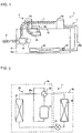
- FIG. 2 is a circuit diagram showing the first air-conditioning apparatus 3 in Embodiment 1 of the present invention.
- the first air-conditioning apparatus 3 includes a first outdoor unit 3a and an indoor unit 3b.
- the first outdoor unit 3a is installed outside an air-conditioned space 10a and includes a first compressor 31, a first flow path switching unit 32, and a first outdoor heat exchanger 33.
- the indoor unit 3b is installed at a ceiling 12 inside the air-conditioned space 10a and includes a first expansion unit 34 and an indoor heat exchanger 35.
- an air inlet (not shown) through which indoor air in the air-conditioned space 10a is sucked is provided in a lower surface thereof, and an air outlet (not shown) through which air is blown out to the air-conditioned space 10a is provided around the air inlet.
- the first compressor 31, the first flow path switching unit 32, the first outdoor heat exchanger 33, the first expansion unit 34, and the indoor heat exchanger 35 are connected to each other by a first refrigerant pipe 30a to form a first refrigerant circuit 30 in which refrigerant flows.
- the first compressor 31 compresses the refrigerant.
- the first flow path switching unit 32 switches the direction in which the refrigerant flows in the first refrigerant circuit 30.
- the first flow path switching unit 32 switches whether the refrigerant discharged from the first compressor 31 flows to the first outdoor heat exchanger 33 or to the indoor heat exchanger 35, and any of cooling operation and heating operation is performed accordingly.
- the first outdoor heat exchanger 33 exchanges heat between the refrigerant and outdoor air, for example.
- the first expansion unit 34 expands the refrigerant and reduces the pressure of the refrigerant, and is, for example, an electromagnetic expansion valve whose opening degree is adjusted.
- the indoor heat exchanger 35 exchanges heat between the refrigerant and the indoor air in the air-conditioned space 10a.
- FIG. 3 is a circuit diagram showing the second air-conditioning apparatus 4 in Embodiment 1 of the present invention.
- the second air-conditioning apparatus 4 includes a second outdoor unit 4a, a pump 47, and an underfloor heat exchanger 48.
- the second outdoor unit 4a is installed outside the air-conditioned space 10a and includes a second compressor 41, a second flow path switching unit 42, a second outdoor heat exchanger 43, a second expansion unit 44, and a water-refrigerant heat exchanger 45.
- the pump 47 and the underfloor heat exchanger 48 are installed under a floor 14 inside the air-conditioned space 10a.
- the second compressor 41, the second flow path switching unit 42, the second outdoor heat exchanger 43, the second expansion unit 44, and the water-refrigerant heat exchanger 45 are connected to each other by a second refrigerant pipe 40a to form a second refrigerant circuit 40 in which refrigerant flows.
- the pump 47, the water-refrigerant heat exchanger 45, and the underfloor heat exchanger 48 are connected to each other by a water pipe 46a to form a water circuit 46 in which water flows.
- a heat medium flowing in the water circuit 46 is not limited to water and may be brine or other media.
- the second compressor 41 compresses the refrigerant.
- the second flow path switching unit 42 switches the direction in which the refrigerant flows in the second refrigerant circuit 40.
- the second flow path switching unit 42 switches whether the refrigerant discharged from the second compressor 41 flows to the second outdoor heat exchanger 43 or the water-refrigerant heat exchanger 45. Accordingly, any of cooling operation and heating operation is performed.
- the second outdoor heat exchanger 43 exchanges heat between the refrigerant and outdoor air, for example.
- the second expansion unit 44 expands the refrigerant and reduces the pressure of the refrigerant, and is, for example, an electromagnetic expansion valve whose opening degree is adjusted.
- the water-refrigerant heat exchanger 45 exchanges heat between the refrigerant and the water flowing through the water pipe 46a.
- the pump 47 circulates the water flowing through the water pipe 46a.
- the underfloor heat exchanger 48 exchanges heat between the indoor air in the air-conditioned space 10a and the water.
- FIG. 4 is a perspective view showing the air-conditioning system 1 according to Embodiment 1 of the present invention.
- the first outdoor unit 3a and the second outdoor unit 4a are installed on a roof floor 11 of a building 10 having the air-conditioned space 10a.
- the case where two first outdoor units 3a are installed is shown as an example.
- the number of first outdoor units 3a may be one or more than two.
- the indoor unit 3b is installed at the ceiling 12 in the air-conditioned space 10a.
- the case where three indoor units 3b are installed is shown.
- the number of first outdoor units 3a may be one, two, or more than 3.
- Lighting 15 for illuminating the air-conditioned space 10a is further installed at the ceiling 12.
- Each indoor unit 3b may be embedded in the ceiling 12 or may be suspended from the ceiling 12.
- each indoor unit 3b may be installed at a wall 13 of the air-conditioned space 10a near the ceiling 12.
- the air inlet is provided in the upper surface of the indoor unit 3b
- the air outlet is provided in the lower surface of the indoor unit 3b.
- each indoor unit 3b may be installed in a space above the ceiling.
- a ceiling air inlet and a ceiling air outlet are provided in the ceiling 12, and the air in the space above the ceiling and the air in the air-conditioned space 10a flow through the ceiling air inlet and the ceiling air outlet therebetween.
- the ceiling air inlet is provided near the lighting 15.
- the underfloor heat exchanger 48 is installed under the floor 14 in the air-conditioned space 10a.
- Windows 16 that are freely opened or closed by the user of the air-conditioned space 10a are provided in the wall 13 of the air-conditioned space 10a.
- the controller 6 is mounted on the wall 13 of the air-conditioned space 10a.
- the air-conditioned space 10a is an office space, and, for example, fixtures such as office desks, chairs, shelves, and whiteboards, OA equipment such as personal computers and printers, and dividers and walls for dividing the air-conditioned space 10a are provided in the air-conditioned space 10a as appropriate.
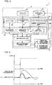
- FIG. 5 is a block diagram showing the controller 6 in Embodiment 1 of the present invention.
- the storage unit 5 stores operation data 51, a catalog 52, a lower limit load 53, apparatus rankings 54, and a processing proportion 55.
- the operation data 51 is an operation status collected by the controller 6 from the first air-conditioning apparatus 3 and the second air-conditioning apparatus 4.
- the operation data 51 includes, for example, information from which it is possible to directly or indirectly acquire the amount of heat supplied by the first air-conditioning apparatus 3 and the second air-conditioning apparatus 4 to the air-conditioned space 10a, and information about air quality such as the air temperature and the air humidity of the air-conditioned space 10a.
- the amount of heat supplied by the first air-conditioning apparatus 3 is estimated, for example, by using a pre-stored characteristic expression for the first compressor 31 on time-sequentially acquired data of the pressure of the refrigerant at the suction side of the first compressor 31, which is provided in the first outdoor unit 3a, the pressure of the refrigerant at the discharge side of the first compressor 31, and the rotation speed of the first compressor 31.
- the amount of heat supplied by the second air-conditioning apparatus 4 is estimated, for example, by using a pre-stored characteristic expression for the second compressor 41 on time-sequentially acquired data of the pressure of the refrigerant at the suction side of the second compressor 41, which is provided in the second outdoor unit 4a, the pressure of the refrigerant at the discharge side of the second compressor 41, and the rotation speed of the second compressor 41.
- the amount of heat supplied by the indoor unit 3b of the first heat exchanger to the air-conditioned space 10a is estimated, for example, by using a pre-stored characteristic expression for the indoor heat exchanger 35 on the basis of the rotation speed of a fan (not shown) provided to the indoor unit 3b and the temperature of the refrigerant flowing into the indoor unit 3b.
- the operation data 51 may include information about weather such as the outdoor temperature and the amount of solar radiation when the first air-conditioning apparatus 3 and the second air-conditioning apparatus 4 are operating, and information about the operation status in the air-conditioned space 10a such as the number of persons present in the air-conditioned space 10a, the operation status of a computing device such as a personal computer, and the operation statuses of the lighting 15.
- FIG. 6 shows graphs showing controllability of the air-conditioning apparatus 2 in Embodiment 1 of the present invention.
- the catalog 52 indicates the characteristics of the respective air-conditioning apparatuses 2.
- the controllability of the respective air-conditioning apparatus 2 is quantitatively described in the catalog 52.
- the upper part of FIG. 6 is a graph showing the relationship between time and load
- the lower part of FIG. 6 is a graph showing the relationship between time and the temperature of the air in the air-conditioned space 10a and indicates that the temperature of the air maintained at a set temperature changes in response to fluctuation of the load.
- the air-conditioning apparatus 2 having good controllability has a short time taken to reach the set temperature after the load changes, as compared to the air-conditioning apparatus 2 having poor controllability (a broken line).
- the catalog 52 is created in advance by a test conducted for the controllability of each air-conditioning apparatus 2 in an environmental test lab in which it is possible to change, for example, the temperature and the humidity of the air and the load as appropriate.
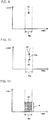
- FIG. 7 is a graph indicating load in Embodiment 1 of the present invention.
- the lower limit load 53 is a load that occurs at a minimum, in a load that occurs in the air-conditioned space 10a and that changes depending on a time period.
- a load obtained by adding, to the lower limit load 53, a fluctuating load 72 that occurs over the lower limit load 53 is a whole load 71 that occurs in the air-conditioned space 10a.
- the apparatus rankings 54 are rankings in which the plurality of air-conditioning apparatuses 2 are ranked in the order of better controllability.
- the apparatus rankings 54 are created with reference to the catalog 52 in the order of a shorter time taken to reach the set temperature, for example.
- the load to be processed by the air-conditioning apparatus 2 changes when the set temperature changes.
- the apparatus rankings 54 may be created in the order of a shorter time taken until the temperature of the air reaches the set temperature when the set temperature is changed.
- the first air-conditioning apparatus 3 is at the first place
- the second air-conditioning apparatus 4 is at the second place.
- the processing proportion 55 is the proportion of the load to be processed by each of the air-conditioning apparatuses 2 that are at the second place and subsequent places in the apparatus rankings 54. Specifically, the processing proportion 55 is the proportion at which each of the air-conditioning apparatuses 2 that are at the second place and subsequent places in the apparatus rankings 54 processes the lower limit load 53.
- a proportion obtained by subtracting the total proportion is determined as the proportion at which the air-conditioning apparatus 2 that is at the first place in the apparatus rankings 54 processes the lower limit load 53.
- the processing proportion 55 may include the proportion at which the air-conditioning apparatus 2 that is at the first place in the apparatus rankings 54 processes the lower limit load 53. In this case, the sum of the processing proportions 55 for the respective air-conditioning apparatuses 2 is 100%. The processing proportion 55 for the air-conditioning apparatus 2 that is at the first place in the apparatus rankings 54 is less than 100%. This is because, when the processing proportion 55 for the air-conditioning apparatus 2 that is at the first place in the apparatus rankings 54 is 100%, the processing proportion 55 for each of the air-conditioning apparatuses 2 that are at the second place and subsequent places in the apparatus rankings 54 is 0% and the whole load is to be processed by the air-conditioning apparatus 2 that is at the first place in the apparatus rankings 54.
- the storage unit 5 may be included in the controller 6.
- the storage unit 5 may be included in a personal computer, a server, or another device that is capable of communicating with the controller 6.
- the storage unit 5 is described as a shared single storage device as an example, but may be a plurality of storage devices.
- the operation data 51, the catalog 52, the lower limit load 53, the apparatus rankings 54, and the processing proportion 55 may be stored in the respective storage devices.
- the controller 6 is connected to the internet 8 as described above, and transmits and receives information to and from an external server as necessary. As shown in FIG. 5 , the controller 6 includes a determination unit 61, an input unit 62, an extraction unit 63, a distribution unit 64, and an air-conditioning control unit 65.
- the determination unit 61 refers to the catalog 52, determines how good the controllability of the corresponding air-conditioning apparatus 2 is, and creates the apparatus rankings 54.
- the determination unit 61 may be included in a personal computer, a server, or another device that is capable of communicating with the controller 6.
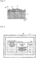
- FIG. 8 is a schematic diagram showing the controller 6 in Embodiment 1 of the present invention.
- the input unit 62 inputs the processing proportion 55 of the load to be processed by each of the air-conditioning apparatuses 2 that are at the second place and subsequent places in the apparatus rankings 54.
- the input unit 62 is provided in the controller 6, and is a touch panel, for example.
- the user designates, for example, the name 54a of each air-conditioning apparatus 2 in accordance with an instruction on the screen by using the input unit 62. For example, a text such as "Please input a processing proportion" is displayed on the screen of the input unit 62.
- the controller 6 stores the processing proportion 55 input with the input unit 62, in the storage unit 5.
- the input unit 62 may be provided so as to be separate from the controller 6.
- the input unit 62 may be included in, for example, a server or another device. In this case, the user designates, for example, the name of each air-conditioning apparatus 2 to the controller 6 via the internet 8 by using the input unit 62 included in the server.
- the extraction unit 63 extracts the lower limit load 53 and includes a load prediction unit 63a and an error calculation unit 63b.
- FIG. 9 is a graph showing a load 70 predicted in Embodiment 1 of the present invention.
- the load prediction unit 63a predicts a load that will occur in the air-conditioned space 10a, on the basis of the operation data 51 and an air-conditioning situation that can occur in a control period.
- the load prediction unit 63a predicts a load, for example, by matching the operation data 51 and weather forecast information in a control period.
- the load prediction unit 63a refers to weather information or other information from the operation data 51.
- the horizontal axis represents time and the vertical axis represents load in FIG. 9
- the load 70 predicted by the load prediction unit 63a is plotted in a target time period 70a as shown in FIG. 9 .
- the load prediction unit 63a may predict a load for each of items such as an amount of heat obtained from the wall 13, an amount of heat obtained from a glass surface of the window 16, an amount of heat generated by a person, and an amount of heat generated by electrical equipment, on the basis of information influencing change of thermal load demand tendency, for example, fluctuation patterns of weather such as the outdoor temperature and the amount of solar radiation, and the fluctuation pattern of the number of persons present in the air-conditioned space 10a.
- an air-conditioning thermal load model for the building 10 is created, and a thermal load is calculated by using the air-conditioning thermal load.
- FIG. 10 is a graph showing the lower limit load 53 in Embodiment 1 of the present invention.
- the error calculation unit 63b calculates the lower limit of errors occurring in a load that occurs in the air-conditioned space 10a, and calculates the lower limit load 53.
- the load that occurs in the air-conditioned space 10a is a load predicted by the load prediction unit 63a.
- the error calculation unit 63b calculates an error by using a method of error analysis, for example.
- deviation ⁇ Q Qpredict - Qreal.
- the average value of a population of the deviation ⁇ Q and the variance of the population that is, unbiased estimate of population variance, are calculated.
- an error of the deviation ⁇ Q is estimated by multiplying the t distribution of Student determined in accordance with the number of samples of the deviation ⁇ Q, by the unbiased estimate of population variance.
- the error calculation unit 63b calculates variations from the predicted load and estimates an upper limit load and the lower limit load 53.
- an error bar 53a indicating the error value calculated by the error calculation unit 63b is plotted with the predicted load 70 as a starting point as shown in FIG. 10 .
- the lower end of the error bar 53a is the lower limit load 53.
- the error calculation unit 63b statically obtains an error from the thermal load predicted on the basis of the operation data 51.
- the average value of the deviation ⁇ Q is 10
- the unbiased estimate of population variance is 0.5
- the number of samples of the deviation ⁇ Q is 10.
- the value of t that achieves a confidence level of 99% is 3.250.
- the deviation ⁇ Q falls within the range of 10 ⁇ 1.625 at 99% confidence.
- the deviation ⁇ Q is out of the range of 10+1.625 with a probability of 1%.
- the extraction unit 63 outputs the lower limit load 53 as the value of a load having a high occurrence probability, in the load that can occur in the control period.
- the lower limit load 53 changes depending on sampling in a time period in which control is to be performed.
- the load to be processed by the air-conditioning system 1 depends on weather conditions such as the outdoor temperature and the amount of solar radiation.
- the load to be processed by the air-conditioning system 1 changes depending on a time period in a day. For example, in the case where cooling operation is performed, when the conditions other than a time period are the same, the load to be processed decreases in a time period in morning in which the outdoor temperature is relatively high and the amount of solar radiation is small.
- the load to be processed increases.
- the time period in which control is to be performed is divided by long time such as 24 hours
- the lower limit load 53 is calculated with, as a reference, the load to be processed which is relatively low in morning. Therefore, the lower limit load 53 is low over 24 hours.
- the time period in which control is to be performed is divided by short time such as 10 minutes
- the lower limit load 53 is calculated with, as a reference, the load to be processed in each time period. Therefore, the lower limit load 53 increases in the time period in which the load to be processed is high, and the lower limit load 53 decreases in the time period in which the load to be processed is low.
- the extraction unit 63 may be included in a personal computer, a server, or another device that is capable of communicating with the controller 6.
- a predicted load, the lower limit load 53, and an error being calculated it is possible to perform control with high accuracy.
- the predetermined fluctuation pattern of the load may be stored in the storage unit 5.
- the distribution unit 64 distributes a proportion at which the lower limit load 53 extracted by the extraction unit 63 is to be processed, as the processing proportion 55 stored in the storage unit 5. Specifically, the distribution unit 64 distributes the load to be processed by the air-conditioning apparatus 2, on the basis of the processing proportion 55, the apparatus rankings 54, and the lower limit load 53.
- the distribution unit 64 includes a calculation device that calculates a load to be assigned to each air-conditioning apparatus 2, on the basis of, for example, the processing proportion 55, the apparatus rankings 54, and the lower limit load 53.
- the first air-conditioning apparatus 3 which is a direct expansion type air-conditioning apparatus
- the second air-conditioning apparatus 4 which is a floor cooling and heating apparatus
- the first air-conditioning apparatus 3 is at the first place
- the second air-conditioning apparatus 4 is at the second place in the apparatus rankings 54 as described above.
- the processing proportion 55 for the second air-conditioning apparatus 4 is 70%
- the processing proportion 55 for the first air-conditioning apparatus 3 is 30%.
- the distribution unit 64 assigns 70 kW to the second air-conditioning apparatus 4.
- FIGs. 11 and 12 are each a graph showing a first distribution example of the processing proportion 55 in Embodiment 1 of the present invention.
- the first distribution example illustrates the case where the processing proportion 55 for the second air-conditioning apparatus 4, which is at the second place in the apparatus rankings 54, is 100%. Since the processing proportion 55 for the second air-conditioning apparatus 4 is 100% as shown in FIG. 11 , the distribution unit 64 assigns the entire lower limit load 53 to the second air-conditioning apparatus 4. Then, as shown in FIG. 12 , the distribution unit 64 assigns the fluctuating load 72 to the first air-conditioning apparatus 3. Here, during real control, the amount of heat equivalent to the lower limit load 53 is continuously processed by the second air-conditioning apparatus 4.
- the second air-conditioning apparatus 4 Since the amount of heat to be processed is the lower limit load 53 in the target time period in which control is to be performed, the second air-conditioning apparatus 4 does not excessively process the load. Then, the fluctuating load 72, which is not processed by the second air-conditioning apparatus 4, is processed by the first air-conditioning apparatus 3 having better controllability than the second air-conditioning apparatus 4. Accordingly, the whole load 71 is processed without excess and deficiency, and the temperature of the air in the air-conditioned space 10a is maintained at the set temperature.
- FIGs. 13 and 14 are each a graph showing a second distribution example of the processing proportion 55 in Embodiment 1 of the present invention.
- the second distribution example illustrates the case where the processing proportion 55 for the second air-conditioning apparatus 4, which is at the second place in the apparatus rankings 54, is 20%. Since the processing proportion 55 for the second air-conditioning apparatus 4 is 20% as shown in FIG. 13 , the distribution unit 64 assigns 20% of the lower limit load 53 to the second air-conditioning apparatus 4. Since the processing proportion 55 for the second air-conditioning apparatus 4 is 20%, the processing proportion 55 for the first air-conditioning apparatus 3 is 80%. As shown in FIG. 14 , the distribution unit 64 assigns 80% of the lower limit load 53 and the fluctuating load 72 to the first air-conditioning apparatus 3. Accordingly, the whole load 71 is processed without excess and deficiency, and the temperature of the air in the air-conditioned space 10a is maintained at the set temperature.
- FIG. 15 is a graph showing a third distribution example of the processing proportion 55 in Embodiment 1 of the present invention.
- the third distribution example illustrates the case where a third air-conditioning apparatus 9 that is at the third place in the apparatus rankings 54 is provided, the processing proportion 55 for the second air-conditioning apparatus 4, which is at the second place in the apparatus rankings 54, is 30%, and the third air-conditioning apparatus 9, which is at the third place in the apparatus rankings 54, is 50%.
- the distribution unit 64 assigns 30% of the lower limit load 53 to the second air-conditioning apparatus 4 and assigns 50% of the lower limit load 53 to the third air-conditioning apparatus 9.
- the processing proportion 55 for the second air-conditioning apparatus 4 is 30% and the processing proportion 55 for the third air-conditioning apparatus 9 is 50%, the processing proportion 55 for the first air-conditioning apparatus 3 is 20%. Then, the distribution unit 64 assigns 20% of the lower limit load 53 and the fluctuating load 72 to the first air-conditioning apparatus 3. Accordingly, the whole load 71 is processed without excess and deficiency, and the temperature of the air in the air-conditioned space 10a is maintained at the set temperature.
- the first air-conditioning apparatus 3 processes the fluctuating load 72 and the rest of the lower limit load 53 that is not processed by the air-conditioning apparatuses 2 that are at the second place and subsequent places in the apparatus rankings 54.
- the first air-conditioning apparatus 3 having good controllability processes the load according to own control such that the set temperature is satisfied.
- the processing proportion 55 for the air-conditioning apparatus 2 that is at the first place in the apparatus rankings 54 may not be stored.
- the processing proportion 55 for the air-conditioning apparatus 2 that is at the first place in the apparatus rankings 54 is set to 100%, the processing proportions 55 for the air-conditioning apparatuses 2 that are at the second place and subsequent places in the apparatus rankings 54 are 0% and thus the air-conditioning apparatuses 2 stop. Therefore, only the processing proportions 55 for the air-conditioning apparatuses 2 that are at the second place and subsequent places in the apparatus rankings 54 may be stored. Since the total proportion is 100%, the processing proportion 55 for the air-conditioning apparatus 2 that is at the first place in the apparatus rankings 54 is obtained by subtracting the processing proportions 55 for the air-conditioning apparatuses 2 that are at the second place and subsequent places in the apparatus rankings 54, from 100%.
- the air-conditioning control unit 65 controls each of the air-conditioning apparatuses 2 that are at the second place and subsequent places in the apparatus rankings 54, such that the lower limit load 53 is processed at the processing proportion 55 distributed by the distribution unit 64, and controls the air-conditioning apparatus 2 that is at the first place in the apparatus rankings 54, such that the remaining load of the lower limit load 53 and the fluctuating load 72 occurring over the lower limit load 53 are processed.
- the first air-conditioning apparatus 3 has cooling operation and heating operation as the operation modes.
- the refrigerant flows in order of the first compressor 31, the first flow path switching unit 32, the first outdoor heat exchanger 33, the first expansion unit 34, and the indoor heat exchanger 35, and the indoor space is caused to exchange heat with the refrigerant in the indoor heat exchanger 35, so that the indoor space is cooled.
- the refrigerant flows in order of the first compressor 31, the first flow path switching unit 32, the indoor heat exchanger 35, the first expansion unit 34, and the first outdoor heat exchanger 33, and the indoor space is caused to exchange heat with the refrigerant in the indoor heat exchanger 35, so that the indoor space is heated.
- the first air-conditioning apparatus 3 operates such that the indoor temperature is maintained at the set temperature on the basis of the contents set by the user via the controller 6.
- the cooling operation will be described.
- the refrigerant sucked into the first compressor 31 is compressed by the first compressor 31 and discharged in a high-temperature and high-pressure gas state.
- the refrigerant discharged from the first compressor 31 in a high-temperature and high-pressure gas state flows through the first flow path switching unit 32 into the first outdoor heat exchanger 33 and is caused to exchange heat with outdoor air to condense and liquify in the first outdoor heat exchanger 33.
- the condensed refrigerant in a liquid state flows into the first expansion unit 34 and is expanded and reduced in pressure into a two-phase gas-liquid state in the first expansion unit 34.
- the refrigerant in a two-phase gas-liquid state flows into the indoor heat exchanger 35 and is caused to exchange heat with the indoor air to evaporate and gasify in the indoor heat exchanger 35.
- the indoor air in the air-conditioned space 10a is cooled and cooling is performed.
- the evaporated refrigerant in a gas state flows through the first flow path switching unit 32 and is sucked into the first compressor 31.
- the heating operation will be described.
- the refrigerant sucked into the first compressor 31 is compressed by the first compressor 31 and discharged in a high-temperature and high-pressure gas state.
- the refrigerant discharged from the first compressor 31 in a high-temperature and high-pressure gas state flows through the first flow path switching unit 32 into the indoor heat exchanger 35 and is caused to exchange heat with the indoor air to condense and liquify in the indoor heat exchanger 35.
- the indoor air in the air-conditioned space 10a is heated and heating is performed.
- the condensed refrigerant in a liquid state flows into the first expansion unit 34 and is expanded and reduced in pressure into a two-phase gas-liquid state in the first expansion unit 34.
- the refrigerant in a two-phase gas-liquid state flows into the first outdoor heat exchanger 33 and is caused to exchange heat with the outdoor air to evaporate and gasify in the first outdoor heat exchanger 33.
- the evaporated refrigerant in a gas state flows through the first flow path switching unit 32 and is sucked into the first compressor 31.
- the second air-conditioning apparatus 4 has cooling operation and heating operation as the operation modes.
- the refrigerant flows in order of the second compressor 41, the second flow path switching unit 42, the second outdoor heat exchanger 43, the second expansion unit 44, and the water-refrigerant heat exchanger 45 in the second refrigerant circuit 40, water flows in order of the pump 47, the water-refrigerant heat exchanger 45, and the underfloor heat exchanger 48 in the water circuit 46, and the indoor air is caused to exchange heat with the water to be cooled in the underfloor heat exchanger 48.
- the refrigerant flows in order of the second compressor 41, the second flow path switching unit 42, the water-refrigerant heat exchanger 45, the second expansion unit 44, and the second outdoor heat exchanger 43 in the second refrigerant circuit 40, water flows in order of the pump 47, the water-refrigerant heat exchanger 45, and the underfloor heat exchanger 48 in the water circuit 46, and the indoor air is caused to exchange heat with the water to be heated in the underfloor heat exchanger 48.
- the second air-conditioning apparatus 4 operates such that the indoor temperature is maintained at the set temperature on the basis of the contents set by the user via the controller 6.
- the cooling operation will be described.
- the refrigerant sucked into the second compressor 41 is compressed by the second compressor 41 and discharged in a high-temperature and high-pressure gas state.
- the refrigerant discharged from the second compressor 41 in a high-temperature and high-pressure gas state flows through the second flow path switching unit 42 into the second outdoor heat exchanger 43 and is caused to exchange heat with the outdoor air to condense and liquify in the second outdoor heat exchanger 43.
- the condensed refrigerant in a liquid state flows into the second expansion unit 44 and is expanded and reduced in pressure into a two-phase gas-liquid state in the second expansion unit 44. Then, the refrigerant in a two-phase gas-liquid state flows into the water-refrigerant heat exchanger 45 and is caused to exchange heat with the water to evaporate and gasify in the water-refrigerant heat exchanger 45. At this time, the water in the water circuit 46 is cooled.
- the evaporated refrigerant in a gas state flows through the first flow path switching unit 32 and is sucked into the first compressor 31.
- the water discharged from the pump 47 flows into the water-refrigerant heat exchanger 45 and is caused to exchange heat with the refrigerant to be cooled in the water-refrigerant heat exchanger 45.
- the cooled water flows into the underfloor heat exchanger 48 and is caused to exchange heat with the indoor air to be heated in the underfloor heat exchanger 48.
- the indoor air in the air-conditioned space 10a is cooled and cooling is performed.
- the heated water is sucked into the pump 47.
- the heating operation in the second refrigerant circuit 40, the refrigerant sucked into the second compressor 41 is compressed by the second compressor 41 and discharged in a high-temperature and high-pressure gas state.
- the refrigerant discharged from the second compressor 41 in a high-temperature and high-pressure gas state flows through the second flow path switching unit 42 into the water-refrigerant heat exchanger 45 and is caused to exchange heat with the water to condense and liquify in the water-refrigerant heat exchanger 45. At this time, the water in the water circuit 46 is heated.
- the condensed refrigerant in a liquid state flows into the second expansion unit 44 and is expanded and reduced in pressure into a two-phase gas-liquid state in the second expansion unit 44. Then, the refrigerant in a two-phase gas-liquid state flows into the second outdoor heat exchanger 43 and is caused to exchange heat with outdoor air to evaporate and gasify in the second outdoor heat exchanger 43.
- the evaporated refrigerant in a gas state flows through the second flow path switching unit 42 and is sucked into the second compressor 41.
- the water discharged from the pump 47 flows into the water-refrigerant heat exchanger 45 and is caused to exchange heat with the refrigerant to be heated in the water-refrigerant heat exchanger 45.
- the heated water flows into the underfloor heat exchanger 48 and is caused to exchange heat with the indoor air to be cooled in the underfloor heat exchanger 48.
- the indoor air in the air-conditioned space 10a is heated and heating is performed.
- the cooled water is sucked into the pump 47.
- FIG. 16 is a flowchart showing operation of the air-conditioning system 1 according to Embodiment 1 of the present invention.
- operation of the air-conditioning system 1 according to Embodiment 1 of the present invention will be described.
- pre-operation before real control of the air-conditioning system 1 is performed will be described.
- the air-conditioning system 1 starts to operate (step ST1)
- the operation data 51 is stored in the storage unit 5.
- the catalog 52 is referred to, and the controllability of each air-conditioning apparatus 2 is determined (step ST2).
- the user inputs the processing proportion 55 reflecting intention of the user by using the input unit 62 (step ST3).
- the processing proportion 55 for the air-conditioning apparatus 2 that is at the first place in the apparatus rankings 54 is also input.
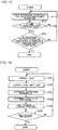
- FIG. 17 is a flowchart showing operation of the air-conditioning system 1 according to Embodiment 1 of the present invention.
- step ST3 when the processing proportion 55 for each air-conditioning apparatus 2 is input (step ST11), whether the sum of the processing proportions 55 for the respective air-conditioning apparatuses 2 is 100% is determined (step ST12).
- step ST12 when the sum of the processing proportions 55 for the respective air-conditioning apparatuses 2 is not 100% (No in step ST12), the operation returns to step ST11.
- the sum of the processing proportions 55 for the respective air-conditioning apparatuses 2 is 100% (Yes in step ST12), whether the processing proportion 55 for the air-conditioning apparatus 2 that is at the first place in the apparatus rankings 54 is less than 100% is determined (step ST13).
- step ST13 When the processing proportion 55 for the air-conditioning apparatus 2 that is at the first place in the apparatus rankings 54 is 100% (No in step ST13), the operation returns to step ST11. On the other hand, when the processing proportion 55 for the air-conditioning apparatus 2 that is at the first place in the apparatus rankings 54 is less than 100% (Yes in step ST13), the pre-operation ends. Since the apparatus rankings 54 is required in input with the input unit 62, input with the input unit 62 is performed after the controllability of each air-conditioning apparatus 2 is determined.
- FIG. 18 is a flowchart showing operation of the air-conditioning system 1 according to Embodiment 1 of the present invention.
- a load is predicted by the load prediction unit 63a (step ST21).
- the lower limit load 53 is extracted by the error calculation unit 63b (step ST22).
- the proportion at which the lower limit load 53 is to be processed is distributed by the distribution unit 64 as the processing proportion 55 stored in the storage unit 5 (step ST23).
- the load to be processed by each air-conditioning apparatus 2 is determined (step ST24).
- a command of control contents is given to each air-conditioning apparatus 2 by the air-conditioning control unit 65 (step ST25).
- whether a control time has ended is determined (step ST26). When the control time is remaining (No in step ST26), the operation returns to step ST21. When the control time has ended (Yes in step ST26), the control ends.
- the proportion at which the lower limit load 53 extracted by the extraction unit 63 is to be processed is distributed as the processing proportion 55 stored in the storage unit 5.
- the user of the air-conditioned space 10a is allowed to store a desired processing proportion 55 in the storage unit 5 in advance. Therefore, a comfortable air-conditioning system 1 in which intention of the user of the air-conditioned space 10a is reflected is realized.
- an air-conditioning system has been known in which an operation plan that minimizes or maximizes an objective function is created on the basis of mathematical programming.
- operation of each air-conditioning apparatus depends on a method for determining the objective function, and thus intention of a user of an air-conditioned space is not reflected.
- the floor cooling and heating apparatus may mainly operate, or the direct expansion type air-conditioning apparatus may mainly operate.
- it is difficult for the user of the air-conditioned space to set an objective function such that desired operation is achieved.
- the plan correction is desired to follow real control in real time.
- the calculation load on a controller increases as the cycle in which the plan is corrected is shorter.
- Embodiment 1 the fluctuating load 72 occurring over the lower limit load 53 is processed by the air-conditioning apparatus 2 that is at the first place in the apparatus rankings 54, and thus plan correction is unnecessary. Therefore, an increase in the calculation load on the controller 6 is reduced. Accordingly, the life of the air-conditioning system 1 is extended.
- the apparatus rankings 54 stored in the storage unit 5 are created in the order of a shorter time taken to reach the set temperature.
- the controllability of the air-conditioning apparatus 2 is better as the time taken to reach the set temperature is shorter.
- the time taken to reach the set temperature is an index for how good the controllability is.
- the apparatus rankings 54 stored in the storage unit 5 are created with reference to the catalog 52 indicating the characteristics of each air-conditioning apparatus 2.
- the accuracy of the apparatus rankings 54 is high since reference is made to the catalog 52 indicating the characteristics of the air-conditioning apparatuses 2.
- the input unit 62 for inputting the processing proportion 55 of the load to be processed by each of the air-conditioning apparatuses 2 that are at the second place and subsequent places in the apparatus rankings 54 is further provided, and the controller 6 has a function to store the processing proportion 55 input with the input unit 62, in the storage unit 5.
- the air-conditioning system 1 since the air-conditioning system 1 includes the input unit 62, it is possible to further reflect intention of the user.
- the extraction unit 63 has the error calculation unit 63b that calculates a lower limit of errors occurring in a load that occurs in the air-conditioned space 10a, and calculates the lower limit load 53. Accordingly, it is possible to calculate the lower limit load 53.
- the extraction unit 63 further has the load prediction unit 63a that predicts a load that will occur in the air-conditioned space 10a, on the basis of: the operation data 51 indicating the operation status of each air-conditioning apparatus 2; and an air-conditioning situation that can occur in a control period. Accordingly, it is possible to predict a load that can occur in the control period.
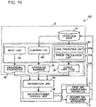
- FIG. 19 is a block diagram showing a controller 106 in Embodiment 2 of the present invention.
- Embodiment 2 is different from Embodiment 1 in that, in an air-conditioning system 100, the controller 106 includes a learning unit 161 instead of the determination unit 61.
- the controller 106 includes a learning unit 161 instead of the determination unit 61.
- parts common to Embodiment 1 are designated by the same reference signs and the description thereof is omitted, and the differences from Embodiment 1 will be mainly described.
- the learning unit 161 refers to the operation data 51, learns how good the controllability of the corresponding air-conditioning apparatus 2 is, and creates the apparatus rankings 54. For example, the learning unit 161 learns a model obtained by calculating how the indoor temperature in the air-conditioned space 10a fluctuates with respect to the contents input with the input unit 62, by referring to the operation data 51. Then, the learning unit 161 learns the controllability of each air-conditioning apparatus 2 by using the calculated model. Specifically, the building 10 is represented by a thermal network model, and a parameter at each portion is determined so as to match a room temperature obtained from the operation data 51 or an amount of heat supplied by the air-conditioning apparatus 2. By using this mode, how the indoor temperature in the air-conditioned space 10a fluctuates with respect to the amount of heat supplied by the air-conditioning apparatus 2 is calculated.
- the learning unit 161 may learn a neural network outputting an indoor temperature, with respect to the contents input with the input unit 62.
- the learning unit 161 may learn the controllability of each air-conditioning apparatus 2 by measurement of a time taken to reach the set temperature again to achieve stability after the set temperature is changed, or by measurement of a time taken for the indoor temperature to reach the set temperature again to achieve stability when the load is changed. At this time, in the apparatus rankings 54, the place is higher in the order of a shorter measured time.
- the learning unit 161 may learn the controllability of each air-conditioning apparatus 2 by measurement of a time taken to reach the set temperature again when the set temperature is changed stepwise after each air-conditioning apparatus 2 singly operates and the indoor temperature reaches the set temperature to bring about a stationary state. At this time, in the apparatus rankings 54, the place is higher in the order of a shorter measured time.
- the apparatus rankings 54 stored in the storage unit 5 are created with reference to the operation data 51 indicating the operation status of each air-conditioning apparatus 2. Accordingly, the catalog 52 becomes unnecessary, and thus the configuration is simplified, and the calculation load on the controller 106 during real control is reduced.
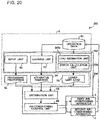
- FIG. 20 is a block diagram showing a controller 206 in Embodiment 3 of the present invention.
- Embodiment 3 is different from Embodiment 2 in that, in an air-conditioning system 200, an extraction unit 263 includes a load estimation unit 263a instead of the load prediction unit 63a.
- an extraction unit 263 includes a load estimation unit 263a instead of the load prediction unit 63a.
- parts common to Embodiments 1 and 2 are designated by the same reference signs and the description thereof is omitted, and the differences from Embodiments 1 and 2 will be mainly described.
- the load estimation unit 263a estimates a load that will occur in the air-conditioned space 10a, on the basis of the present operation status of each air-conditioning apparatus 2. That is, in Embodiment 3, a load during a predetermined period in the future, for example, a load during 30 minutes, is estimated as a load equal to the present load. Then, the error calculation unit 63b calculates the lower limit load 53 of the load estimated by the load estimation unit 263a. In this case, the error calculation unit 63b calculates how much the present load fluctuates during a predetermined period in the future, and calculates the lower limit load 53 on the basis of an error from the present load.
- the extraction unit 263 has the load estimation unit 263a that estimates a load that will occur in the air-conditioned space 10a, on the basis of the present operation status of each air-conditioning apparatus 2. Accordingly, information about an air-conditioning situation that can occur in a control period is unnecessary, and thus the configuration is simplified, and the calculation load on the controller 206 during real control is reduced.
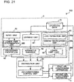
- FIG. 21 is a block diagram showing a controller 306 in Embodiment 4 of the present invention.
- Embodiment 4 is different from Embodiment 2 in that, in an air-conditioning system 300, the controller 306 includes a lower limit determination unit 366.
- the controller 306 includes a lower limit determination unit 366.
- parts common to Embodiments 1, 2, and 3 are designated by the same reference signs and the description thereof is omitted, and the differences from Embodiments 1, 2, and 3 will be mainly described.
- the lower limit determination unit 366 requests re-input to the input unit 62 when the processing proportion 55 input with the input unit 62 is less than a proportion lower limit threshold on the basis of design information of the air-conditioning system 300.
- the lower limit determination unit 366 promotes input of a value equal to or greater than the proportion lower limit threshold.
- the proportion lower limit threshold is set to 30%. Accordingly, the processing proportion 55 for the corresponding air-conditioning apparatus 2 is prevented from being less than 30%. As a result, it is possible to inhibit non-cooling/non-heating due to a capacity shortage.
- the controller 306 has a function to request re-input to the input unit 62 when the processing proportion 55 input with the input unit 62 is less than the proportion lower limit threshold. Accordingly, it is possible to inhibit non-cooling/non-heating due to a capacity shortage.
Landscapes
- Engineering & Computer Science (AREA)
- Chemical & Material Sciences (AREA)
- Combustion & Propulsion (AREA)
- Mechanical Engineering (AREA)
- General Engineering & Computer Science (AREA)
- Signal Processing (AREA)
- Human Computer Interaction (AREA)
- Physics & Mathematics (AREA)
- Fuzzy Systems (AREA)
- Mathematical Physics (AREA)
- Computer Vision & Pattern Recognition (AREA)
- Evolutionary Computation (AREA)
- Medical Informatics (AREA)
- Software Systems (AREA)
- Artificial Intelligence (AREA)
- General Physics & Mathematics (AREA)
- Automation & Control Theory (AREA)
- Health & Medical Sciences (AREA)
- Air Conditioning Control Device (AREA)
Claims (8)
- Système de conditionnement d'air comprenant:- une pluralité d'appareils de conditionnement d'air (2) configurés pour conditionner de l'air dans un espace à air conditionné (10a); le système étant caractérisé en ce qu'il comprend en outre:- une unité de stockage (5) configurée pour stocker un classement d'appareil, créée pour que la pluralité d'appareils de conditionnement d'air (2), pris dans un ordre partant du temps le plus court, atteignent une température définie, et pour stocker une proportion de traitement d'une charge devant être traitée par chacun des appareils de conditionnement d'air (2) qui sont à une deuxième place et à des places suivantes dans le classement d'appareils; et- un contrôleur (6) configuré pour commander un fonctionnement de la pluralité d'appareils de conditionnement d'air (2),
dans lequel le contrôleur (6) inclut- une unité d'extraction (63) configurée pour extraire une charge limite inférieure qui survient à un minimum, dans une charge qui survient dans l'espace à air conditionné (10a) et qui change en dépendance d'une période temporelle,- une unité de distribution (64) configurée pour distribuer une proportion à laquelle la charge limite inférieure extraite par l'unité d'extraction (63) doit être traitée, à titre de proportion de traitement stockée dans l'unité de stockage (5), et- une unité de commande de conditionnement d'air (65) configurée pour commander chacun des appareils de conditionnement d'air (2) qui sont à la deuxième place et à des places suivantes dans le classement d'appareils, de sorte que la charge limite inférieure est traitée au niveau de la proportion de traitement distribuée par l'unité de distribution (64), et pour commander l'appareil de conditionnement d'air (2) qui est à une première place dans le classement d'appareils, de manière à traiter une charge restante de la charge limite inférieure et une charge de fluctuation qui survient au-dessus de la charge limite inférieure. - Système de conditionnement d'air selon la revendication 1,
dans lequel le classement d'appareils stocké dans l'unité de stockage (5) est créé par référence à un catalogue indiquant des caractéristiques de chaque appareil de conditionnement d'air (2). - Dispositif de conditionnement d'air selon la revendication 1 ou 2,
dans lequel le classement d'appareils stocké dans l'unité de stockage (5) est créé par référence à des données de fonctionnement indiquant un état de fonctionnement de chaque appareil de conditionnement d'air (2). - Système de conditionnement d'air selon l'une quelconque des revendications 1 à 3, comprenant en outre une unité d'entrée (62) configurée pour entrer une proportion de traitement d'une charge devant être traitée par chacun des appareils de conditionnement d'air (2) qui sont à la deuxième place et aux places suivantes dans le classement d'appareils, dans lequel le contrôleur (6) a pour fonction de stocker dans l'unité de stockage (5) la proportion de traitement entrée avec l'unité d'entrée (62).
- Système de conditionnement d'air selon la revendication 4,
dans lequel le contrôleur (6) a pour fonction de demander une nouvelle entrée vers l'unité d'entrée (62) quand une proportion de traitement entrée avec l'unité d'entrée (62) est inférieure à un seuil limite inférieur de proportion. - Système de conditionnement d'air selon l'une quelconque des revendications 1 à 5,
dans lequel l'unité d'extraction (63) inclut une unité de calcul d'erreur (63b) configurée pour calculer une limite inférieure d'une erreur survenant dans une charge qui survient dans l'espace à air conditionné (10a), et pour calculer la charge limite inférieure. - Système de conditionnement d'air selon l'une quelconque des revendications 1 à 6,
dans lequel l'unité d'extraction (63) inclut en outre une unité de prédiction de charge (63a) configurée pour prédire une charge qui surviendra dans l'espace à air conditionné (10a), sur la base de données de fonctionnement indiquant un état de fonctionnement de chaque appareil de conditionnement d'air (2) et d'une situation de conditionnement d'air qui peut survenir dans une période de commande. - Système de conditionnement d'air selon l'une quelconque des revendications 1 à 6,
dans lequel l'unité d'extraction (263) inclut en outre une unité d'estimation de charge (263a) configurée pour estimer une charge qui surviendra dans l'espace à air conditionné (10a), sur la base d'un état de fonctionnement actuel de chaque appareil de conditionnement d'air (2).
Applications Claiming Priority (2)
| Application Number | Priority Date | Filing Date | Title |
|---|---|---|---|
| JP2016034634 | 2016-02-25 | ||
| PCT/JP2016/084611 WO2017145465A1 (fr) | 2016-02-25 | 2016-11-22 | Système de climatisation |
Publications (3)
| Publication Number | Publication Date |
|---|---|
| EP3421897A1 EP3421897A1 (fr) | 2019-01-02 |
| EP3421897A4 EP3421897A4 (fr) | 2019-03-06 |
| EP3421897B1 true EP3421897B1 (fr) | 2019-12-25 |
Family
ID=59685072
Family Applications (1)
| Application Number | Title | Priority Date | Filing Date |
|---|---|---|---|
| EP16891621.1A Active EP3421897B1 (fr) | 2016-02-25 | 2016-11-22 | Système de climatisation |
Country Status (4)
| Country | Link |
|---|---|
| US (1) | US10753632B2 (fr) |
| EP (1) | EP3421897B1 (fr) |
| JP (1) | JP6486547B2 (fr) |
| WO (1) | WO2017145465A1 (fr) |
Families Citing this family (6)
| Publication number | Priority date | Publication date | Assignee | Title |
|---|---|---|---|---|
| JP7204328B2 (ja) * | 2018-02-22 | 2023-01-16 | 三菱電機株式会社 | 異常検知装置、異常検知システム、異常検知方法、及び、プログラム |
| CN109347094B (zh) * | 2018-10-24 | 2020-10-09 | 珠海格力电器股份有限公司 | 变流器及其分配电能的方法、装置及电能分配系统 |
| CN109708254B (zh) * | 2018-12-14 | 2020-09-04 | 青岛海信日立空调系统有限公司 | 一种空调器 |
| CN110107994B (zh) * | 2019-05-08 | 2020-04-17 | 珠海格力电器股份有限公司 | 一种室内设定温度的确定方法、装置、存储介质及空调 |
| CN111221262A (zh) * | 2020-03-30 | 2020-06-02 | 重庆特斯联智慧科技股份有限公司 | 一种基于人体特征自适应智能家居调节方法和系统 |
| CN114484735B (zh) * | 2022-03-11 | 2023-08-15 | 青岛海信日立空调系统有限公司 | 多联机系统故障诊断及节能潜力识别方法及多联机系统 |
Family Cites Families (19)
| Publication number | Priority date | Publication date | Assignee | Title |
|---|---|---|---|---|
| US5372015A (en) | 1991-07-05 | 1994-12-13 | Kabushiki Kaisha Toshiba | Air conditioner controller |
| JPH0510568A (ja) | 1991-07-05 | 1993-01-19 | Toshiba Corp | 空調制御装置 |
| JPH07225038A (ja) | 1994-02-15 | 1995-08-22 | Toshiba Corp | 蓄熱プラントの制御装置 |
| JP2004239519A (ja) | 2003-02-06 | 2004-08-26 | Yamaguchi Technology Licensing Organization Ltd | 蓄熱プラントの制御装置 |
| US8127298B2 (en) * | 2008-10-30 | 2012-02-28 | Hitachi, Ltd. | Operations management apparatus of information-processing system |
| JP2010156494A (ja) | 2008-12-26 | 2010-07-15 | Daikin Ind Ltd | 負荷処理バランス設定装置 |
| JP5518431B2 (ja) * | 2009-10-30 | 2014-06-11 | 三洋電機株式会社 | 冷凍装置 |
| JP5662102B2 (ja) * | 2010-10-25 | 2015-01-28 | 富士通株式会社 | 空調システム |
| JP2012097966A (ja) * | 2010-11-02 | 2012-05-24 | Daikin Industries Ltd | 空気調和装置の熱源ユニット及びその制御方法 |
| JP5927694B2 (ja) * | 2012-02-03 | 2016-06-01 | 株式会社日立製作所 | 熱源システムおよび熱源システムの制御方法 |
| EP3644155A1 (fr) * | 2012-03-29 | 2020-04-29 | Google LLC. | Traitement et communication d'informations d'utilisation d'un système cvca commandé par un thermostat connecté à un réseau |
| JP6034211B2 (ja) * | 2013-02-07 | 2016-11-30 | 株式会社東芝 | 運転制御装置、運転制御方法及び運転制御プログラム |
| JP6080204B2 (ja) * | 2013-03-26 | 2017-02-15 | 株式会社Nttファシリティーズ | 空調機台数制御方法 |
| JP5951120B2 (ja) * | 2013-04-22 | 2016-07-13 | 三菱電機株式会社 | 空調制御システム及び空調制御方法 |
| WO2015071979A1 (fr) * | 2013-11-13 | 2015-05-21 | 三菱電機株式会社 | Organe de commande central |
| US9810443B2 (en) * | 2014-12-05 | 2017-11-07 | Honeywell International Inc. | Devices, methods, and systems for data-driven acceleration of deployed services |
| US9869484B2 (en) * | 2015-01-14 | 2018-01-16 | Google Inc. | Predictively controlling an environmental control system |
| JP5994900B1 (ja) * | 2015-05-19 | 2016-09-21 | ダイキン工業株式会社 | 複数の空気調和装置の管理装置 |
| JP6004042B1 (ja) * | 2015-05-19 | 2016-10-05 | ダイキン工業株式会社 | 複数の空気調和装置の管理装置 |
-
2016
- 2016-11-22 US US16/074,829 patent/US10753632B2/en active Active
- 2016-11-22 JP JP2018500989A patent/JP6486547B2/ja active Active
- 2016-11-22 EP EP16891621.1A patent/EP3421897B1/fr active Active
- 2016-11-22 WO PCT/JP2016/084611 patent/WO2017145465A1/fr active Application Filing
Non-Patent Citations (1)
| Title |
|---|
| None * |
Also Published As
| Publication number | Publication date |
|---|---|
| EP3421897A1 (fr) | 2019-01-02 |
| EP3421897A4 (fr) | 2019-03-06 |
| US20190063774A1 (en) | 2019-02-28 |
| JPWO2017145465A1 (ja) | 2018-07-05 |
| WO2017145465A1 (fr) | 2017-08-31 |
| US10753632B2 (en) | 2020-08-25 |
| JP6486547B2 (ja) | 2019-03-20 |
Similar Documents
| Publication | Publication Date | Title |
|---|---|---|
| EP3421897B1 (fr) | Système de climatisation | |
| Ferreira et al. | Neural networks based predictive control for thermal comfort and energy savings in public buildings | |
| Chung et al. | Application of artificial neural networks for determining energy-efficient operating set-points of the VRF cooling system | |
| Li et al. | A real-time optimal control strategy for multi-zone VAV air-conditioning systems adopting a multi-agent based distributed optimization method | |
| Li et al. | Performance of a heat recovery ventilator coupled with an air-to-air heat pump for residential suites in Canadian cities | |
| Zhang et al. | Review of underfloor air distribution technology | |
| Zhu et al. | Online optimal control of variable refrigerant flow and variable air volume combined air conditioning system for energy saving | |
| EP2835594A1 (fr) | Dispositif de commande d'appareil de climatisation et programme de commande d'appareil de climatisation | |
| JP6739671B1 (ja) | 情報処理装置 | |
| EP3007295A1 (fr) | Système de réponse à la demande | |
| EP3617607B1 (fr) | Dispositif de commande de fonctionnement, système de climatiseur, procédé de commande de fonctionnement et programme de commande de fonctionnement | |
| AU2009332323A1 (en) | Load processing balance setting apparatus | |
| Seo et al. | Comparative analysis of cooling energy performance between water-cooled VRF and conventional AHU systems in a commercial building | |
| Yun et al. | Dynamic target high pressure control of a VRF system for heating energy savings | |
| US10612808B2 (en) | Operating an HVAC system based on predicted indoor air temperature | |
| Kang et al. | Modeling, calibration, and sensitivity analysis of direct expansion AHU-Water source VRF system | |
| Matsukawa et al. | Stable segment method for multiple linear regression on baseline estimation for smart grid fast automated demand response | |
| Souayfane et al. | A weather-clustering and energy-thermal comfort optimization methodology for indoor cooling in subtropical desert climates | |
| Ahn et al. | Local vs. integrated control of a variable refrigerant flow system using artificial neural networks | |
| Zhao et al. | Data-driven online energy management framework for HVAC systems: An experimental study | |
| Ferdyn-Grygierek et al. | Optimization of window size design for detached house using TRNSYS simulations and genetic algorithm | |
| Mathews et al. | A tool for integrated HVAC, building, energy and control analysis Part 1: overview of QUICKcontrol | |
| US20210256184A1 (en) | System and Method for Designing Heating, Ventilating, and Air-Conditioning (HVAC) Systems | |
| Gao et al. | Experimental study of a bilinear control for a GSHP integrated air-conditioning system | |
| WO2021171751A1 (fr) | Système et procédé de commande d'un fonctionnement de systèmes de chauffage, ventilation et climatisation (cvc) |
Legal Events
| Date | Code | Title | Description |
|---|---|---|---|
| STAA | Information on the status of an ep patent application or granted ep patent |
Free format text: STATUS: THE INTERNATIONAL PUBLICATION HAS BEEN MADE |
|
| PUAI | Public reference made under article 153(3) epc to a published international application that has entered the european phase |
Free format text: ORIGINAL CODE: 0009012 |
|
| STAA | Information on the status of an ep patent application or granted ep patent |
Free format text: STATUS: REQUEST FOR EXAMINATION WAS MADE |
|
| 17P | Request for examination filed |
Effective date: 20180619 |
|
| AK | Designated contracting states |
Kind code of ref document: A1 Designated state(s): AL AT BE BG CH CY CZ DE DK EE ES FI FR GB GR HR HU IE IS IT LI LT LU LV MC MK MT NL NO PL PT RO RS SE SI SK SM TR |
|
| AX | Request for extension of the european patent |
Extension state: BA ME |
|
| RIC1 | Information provided on ipc code assigned before grant |
Ipc: F24F 11/02 20060101AFI20170901BHEP |
|
| A4 | Supplementary search report drawn up and despatched |
Effective date: 20190205 |
|
| RIC1 | Information provided on ipc code assigned before grant |
Ipc: F24F 11/46 20180101ALI20190130BHEP Ipc: F24F 11/54 20180101AFI20190130BHEP Ipc: F24F 140/50 20180101ALI20190130BHEP Ipc: F24F 11/89 20180101ALI20190130BHEP |
|
| DAV | Request for validation of the european patent (deleted) | ||
| DAX | Request for extension of the european patent (deleted) | ||
| REG | Reference to a national code |
Ref country code: DE Ref legal event code: R079 Ref document number: 602016027097 Country of ref document: DE Free format text: PREVIOUS MAIN CLASS: F24F0011020000 Ipc: F24F0011540000 |
|
| GRAP | Despatch of communication of intention to grant a patent |
Free format text: ORIGINAL CODE: EPIDOSNIGR1 |
|
| STAA | Information on the status of an ep patent application or granted ep patent |
Free format text: STATUS: GRANT OF PATENT IS INTENDED |
|
| RIC1 | Information provided on ipc code assigned before grant |
Ipc: F24F 140/50 20180101ALI20190621BHEP Ipc: F24F 11/46 20180101ALI20190621BHEP Ipc: F24F 11/89 20180101ALI20190621BHEP Ipc: F24F 11/54 20180101AFI20190621BHEP |
|
| INTG | Intention to grant announced |
Effective date: 20190712 |
|
| GRAS | Grant fee paid |
Free format text: ORIGINAL CODE: EPIDOSNIGR3 |
|
| GRAA | (expected) grant |
Free format text: ORIGINAL CODE: 0009210 |
|
| STAA | Information on the status of an ep patent application or granted ep patent |
Free format text: STATUS: THE PATENT HAS BEEN GRANTED |
|
| AK | Designated contracting states |
Kind code of ref document: B1 Designated state(s): AL AT BE BG CH CY CZ DE DK EE ES FI FR GB GR HR HU IE IS IT LI LT LU LV MC MK MT NL NO PL PT RO RS SE SI SK SM TR |
|
| REG | Reference to a national code |
Ref country code: GB Ref legal event code: FG4D |
|
| REG | Reference to a national code |
Ref country code: CH Ref legal event code: EP |
|
| REG | Reference to a national code |
Ref country code: DE Ref legal event code: R096 Ref document number: 602016027097 Country of ref document: DE |
|
| REG | Reference to a national code |
Ref country code: AT Ref legal event code: REF Ref document number: 1217535 Country of ref document: AT Kind code of ref document: T Effective date: 20200115 |
|
| REG | Reference to a national code |
Ref country code: IE Ref legal event code: FG4D |
|
| REG | Reference to a national code |
Ref country code: NL Ref legal event code: MP Effective date: 20191225 |
|
| PG25 | Lapsed in a contracting state [announced via postgrant information from national office to epo] |
Ref country code: FI Free format text: LAPSE BECAUSE OF FAILURE TO SUBMIT A TRANSLATION OF THE DESCRIPTION OR TO PAY THE FEE WITHIN THE PRESCRIBED TIME-LIMIT Effective date: 20191225 Ref country code: BG Free format text: LAPSE BECAUSE OF FAILURE TO SUBMIT A TRANSLATION OF THE DESCRIPTION OR TO PAY THE FEE WITHIN THE PRESCRIBED TIME-LIMIT Effective date: 20200325 Ref country code: NO Free format text: LAPSE BECAUSE OF FAILURE TO SUBMIT A TRANSLATION OF THE DESCRIPTION OR TO PAY THE FEE WITHIN THE PRESCRIBED TIME-LIMIT Effective date: 20200325 Ref country code: SE Free format text: LAPSE BECAUSE OF FAILURE TO SUBMIT A TRANSLATION OF THE DESCRIPTION OR TO PAY THE FEE WITHIN THE PRESCRIBED TIME-LIMIT Effective date: 20191225 Ref country code: LV Free format text: LAPSE BECAUSE OF FAILURE TO SUBMIT A TRANSLATION OF THE DESCRIPTION OR TO PAY THE FEE WITHIN THE PRESCRIBED TIME-LIMIT Effective date: 20191225 Ref country code: LT Free format text: LAPSE BECAUSE OF FAILURE TO SUBMIT A TRANSLATION OF THE DESCRIPTION OR TO PAY THE FEE WITHIN THE PRESCRIBED TIME-LIMIT Effective date: 20191225 Ref country code: GR Free format text: LAPSE BECAUSE OF FAILURE TO SUBMIT A TRANSLATION OF THE DESCRIPTION OR TO PAY THE FEE WITHIN THE PRESCRIBED TIME-LIMIT Effective date: 20200326 |
|
| REG | Reference to a national code |
Ref country code: LT Ref legal event code: MG4D |
|
| PG25 | Lapsed in a contracting state [announced via postgrant information from national office to epo] |
Ref country code: HR Free format text: LAPSE BECAUSE OF FAILURE TO SUBMIT A TRANSLATION OF THE DESCRIPTION OR TO PAY THE FEE WITHIN THE PRESCRIBED TIME-LIMIT Effective date: 20191225 Ref country code: RS Free format text: LAPSE BECAUSE OF FAILURE TO SUBMIT A TRANSLATION OF THE DESCRIPTION OR TO PAY THE FEE WITHIN THE PRESCRIBED TIME-LIMIT Effective date: 20191225 |
|
| PG25 | Lapsed in a contracting state [announced via postgrant information from national office to epo] |
Ref country code: AL Free format text: LAPSE BECAUSE OF FAILURE TO SUBMIT A TRANSLATION OF THE DESCRIPTION OR TO PAY THE FEE WITHIN THE PRESCRIBED TIME-LIMIT Effective date: 20191225 |
|
| PG25 | Lapsed in a contracting state [announced via postgrant information from national office to epo] |
Ref country code: EE Free format text: LAPSE BECAUSE OF FAILURE TO SUBMIT A TRANSLATION OF THE DESCRIPTION OR TO PAY THE FEE WITHIN THE PRESCRIBED TIME-LIMIT Effective date: 20191225 Ref country code: NL Free format text: LAPSE BECAUSE OF FAILURE TO SUBMIT A TRANSLATION OF THE DESCRIPTION OR TO PAY THE FEE WITHIN THE PRESCRIBED TIME-LIMIT Effective date: 20191225 Ref country code: RO Free format text: LAPSE BECAUSE OF FAILURE TO SUBMIT A TRANSLATION OF THE DESCRIPTION OR TO PAY THE FEE WITHIN THE PRESCRIBED TIME-LIMIT Effective date: 20191225 Ref country code: PT Free format text: LAPSE BECAUSE OF FAILURE TO SUBMIT A TRANSLATION OF THE DESCRIPTION OR TO PAY THE FEE WITHIN THE PRESCRIBED TIME-LIMIT Effective date: 20200520 Ref country code: CZ Free format text: LAPSE BECAUSE OF FAILURE TO SUBMIT A TRANSLATION OF THE DESCRIPTION OR TO PAY THE FEE WITHIN THE PRESCRIBED TIME-LIMIT Effective date: 20191225 |
|
| PG25 | Lapsed in a contracting state [announced via postgrant information from national office to epo] |
Ref country code: SM Free format text: LAPSE BECAUSE OF FAILURE TO SUBMIT A TRANSLATION OF THE DESCRIPTION OR TO PAY THE FEE WITHIN THE PRESCRIBED TIME-LIMIT Effective date: 20191225 Ref country code: SK Free format text: LAPSE BECAUSE OF FAILURE TO SUBMIT A TRANSLATION OF THE DESCRIPTION OR TO PAY THE FEE WITHIN THE PRESCRIBED TIME-LIMIT Effective date: 20191225 Ref country code: IS Free format text: LAPSE BECAUSE OF FAILURE TO SUBMIT A TRANSLATION OF THE DESCRIPTION OR TO PAY THE FEE WITHIN THE PRESCRIBED TIME-LIMIT Effective date: 20200425 |
|
| REG | Reference to a national code |
Ref country code: DE Ref legal event code: R097 Ref document number: 602016027097 Country of ref document: DE |
|
| PG25 | Lapsed in a contracting state [announced via postgrant information from national office to epo] |
Ref country code: DK Free format text: LAPSE BECAUSE OF FAILURE TO SUBMIT A TRANSLATION OF THE DESCRIPTION OR TO PAY THE FEE WITHIN THE PRESCRIBED TIME-LIMIT Effective date: 20191225 Ref country code: ES Free format text: LAPSE BECAUSE OF FAILURE TO SUBMIT A TRANSLATION OF THE DESCRIPTION OR TO PAY THE FEE WITHIN THE PRESCRIBED TIME-LIMIT Effective date: 20191225 |
|
| PLBE | No opposition filed within time limit |
Free format text: ORIGINAL CODE: 0009261 |
|
| STAA | Information on the status of an ep patent application or granted ep patent |
Free format text: STATUS: NO OPPOSITION FILED WITHIN TIME LIMIT |
|
| REG | Reference to a national code |
Ref country code: AT Ref legal event code: MK05 Ref document number: 1217535 Country of ref document: AT Kind code of ref document: T Effective date: 20191225 |
|
| PG25 | Lapsed in a contracting state [announced via postgrant information from national office to epo] |
Ref country code: SI Free format text: LAPSE BECAUSE OF FAILURE TO SUBMIT A TRANSLATION OF THE DESCRIPTION OR TO PAY THE FEE WITHIN THE PRESCRIBED TIME-LIMIT Effective date: 20191225 |
|
| 26N | No opposition filed |
Effective date: 20200928 |
|
| PG25 | Lapsed in a contracting state [announced via postgrant information from national office to epo] |
Ref country code: AT Free format text: LAPSE BECAUSE OF FAILURE TO SUBMIT A TRANSLATION OF THE DESCRIPTION OR TO PAY THE FEE WITHIN THE PRESCRIBED TIME-LIMIT Effective date: 20191225 Ref country code: IT Free format text: LAPSE BECAUSE OF FAILURE TO SUBMIT A TRANSLATION OF THE DESCRIPTION OR TO PAY THE FEE WITHIN THE PRESCRIBED TIME-LIMIT Effective date: 20191225 |
|
| PG25 | Lapsed in a contracting state [announced via postgrant information from national office to epo] |
Ref country code: PL Free format text: LAPSE BECAUSE OF FAILURE TO SUBMIT A TRANSLATION OF THE DESCRIPTION OR TO PAY THE FEE WITHIN THE PRESCRIBED TIME-LIMIT Effective date: 20191225 |
|
| PG25 | Lapsed in a contracting state [announced via postgrant information from national office to epo] |
Ref country code: MC Free format text: LAPSE BECAUSE OF FAILURE TO SUBMIT A TRANSLATION OF THE DESCRIPTION OR TO PAY THE FEE WITHIN THE PRESCRIBED TIME-LIMIT Effective date: 20191225 |
|
| REG | Reference to a national code |
Ref country code: CH Ref legal event code: PL |
|
| PG25 | Lapsed in a contracting state [announced via postgrant information from national office to epo] |
Ref country code: LU Free format text: LAPSE BECAUSE OF NON-PAYMENT OF DUE FEES Effective date: 20201122 |
|
| REG | Reference to a national code |
Ref country code: BE Ref legal event code: MM Effective date: 20201130 |
|
| PG25 | Lapsed in a contracting state [announced via postgrant information from national office to epo] |
Ref country code: CH Free format text: LAPSE BECAUSE OF NON-PAYMENT OF DUE FEES Effective date: 20201130 Ref country code: LI Free format text: LAPSE BECAUSE OF NON-PAYMENT OF DUE FEES Effective date: 20201130 |
|
| PG25 | Lapsed in a contracting state [announced via postgrant information from national office to epo] |
Ref country code: FR Free format text: LAPSE BECAUSE OF NON-PAYMENT OF DUE FEES Effective date: 20201130 Ref country code: IE Free format text: LAPSE BECAUSE OF NON-PAYMENT OF DUE FEES Effective date: 20201122 |
|
| PG25 | Lapsed in a contracting state [announced via postgrant information from national office to epo] |
Ref country code: TR Free format text: LAPSE BECAUSE OF FAILURE TO SUBMIT A TRANSLATION OF THE DESCRIPTION OR TO PAY THE FEE WITHIN THE PRESCRIBED TIME-LIMIT Effective date: 20191225 Ref country code: MT Free format text: LAPSE BECAUSE OF FAILURE TO SUBMIT A TRANSLATION OF THE DESCRIPTION OR TO PAY THE FEE WITHIN THE PRESCRIBED TIME-LIMIT Effective date: 20191225 Ref country code: CY Free format text: LAPSE BECAUSE OF FAILURE TO SUBMIT A TRANSLATION OF THE DESCRIPTION OR TO PAY THE FEE WITHIN THE PRESCRIBED TIME-LIMIT Effective date: 20191225 |
|
| PG25 | Lapsed in a contracting state [announced via postgrant information from national office to epo] |
Ref country code: MK Free format text: LAPSE BECAUSE OF FAILURE TO SUBMIT A TRANSLATION OF THE DESCRIPTION OR TO PAY THE FEE WITHIN THE PRESCRIBED TIME-LIMIT Effective date: 20191225 |
|
| PG25 | Lapsed in a contracting state [announced via postgrant information from national office to epo] |
Ref country code: BE Free format text: LAPSE BECAUSE OF NON-PAYMENT OF DUE FEES Effective date: 20201130 |
|
| REG | Reference to a national code |
Ref country code: DE Ref legal event code: R084 Ref document number: 602016027097 Country of ref document: DE |
|
| REG | Reference to a national code |
Ref country code: GB Ref legal event code: 746 Effective date: 20230113 |
|
| P01 | Opt-out of the competence of the unified patent court (upc) registered |
Effective date: 20230512 |
|
| PGFP | Annual fee paid to national office [announced via postgrant information from national office to epo] |
Ref country code: GB Payment date: 20230928 Year of fee payment: 8 |
|
| PGFP | Annual fee paid to national office [announced via postgrant information from national office to epo] |
Ref country code: DE Payment date: 20230929 Year of fee payment: 8 |