EP3421841A1 - Getriebe - Google Patents
Getriebe Download PDFInfo
- Publication number
- EP3421841A1 EP3421841A1 EP17177773.3A EP17177773A EP3421841A1 EP 3421841 A1 EP3421841 A1 EP 3421841A1 EP 17177773 A EP17177773 A EP 17177773A EP 3421841 A1 EP3421841 A1 EP 3421841A1
- Authority
- EP
- European Patent Office
- Prior art keywords
- axial
- radial
- shaft
- shaft shoulder
- bearing unit
- Prior art date
- Legal status (The legal status is an assumption and is not a legal conclusion. Google has not performed a legal analysis and makes no representation as to the accuracy of the status listed.)
- Granted
Links
Images


Classifications
-
- F—MECHANICAL ENGINEERING; LIGHTING; HEATING; WEAPONS; BLASTING
- F16—ENGINEERING ELEMENTS AND UNITS; GENERAL MEASURES FOR PRODUCING AND MAINTAINING EFFECTIVE FUNCTIONING OF MACHINES OR INSTALLATIONS; THERMAL INSULATION IN GENERAL
- F16H—GEARING
- F16H57/00—General details of gearing
- F16H57/0018—Shaft assemblies for gearings
- F16H57/0025—Shaft assemblies for gearings with gearing elements rigidly connected to a shaft, e.g. securing gears or pulleys by specially adapted splines, keys or methods
-
- F—MECHANICAL ENGINEERING; LIGHTING; HEATING; WEAPONS; BLASTING
- F16—ENGINEERING ELEMENTS AND UNITS; GENERAL MEASURES FOR PRODUCING AND MAINTAINING EFFECTIVE FUNCTIONING OF MACHINES OR INSTALLATIONS; THERMAL INSULATION IN GENERAL
- F16H—GEARING
- F16H57/00—General details of gearing
- F16H57/02—Gearboxes; Mounting gearing therein
- F16H57/023—Mounting or installation of gears or shafts in the gearboxes, e.g. methods or means for assembly
-
- F—MECHANICAL ENGINEERING; LIGHTING; HEATING; WEAPONS; BLASTING
- F16—ENGINEERING ELEMENTS AND UNITS; GENERAL MEASURES FOR PRODUCING AND MAINTAINING EFFECTIVE FUNCTIONING OF MACHINES OR INSTALLATIONS; THERMAL INSULATION IN GENERAL
- F16C—SHAFTS; FLEXIBLE SHAFTS; ELEMENTS OR CRANKSHAFT MECHANISMS; ROTARY BODIES OTHER THAN GEARING ELEMENTS; BEARINGS
- F16C17/00—Sliding-contact bearings for exclusively rotary movement
- F16C17/10—Sliding-contact bearings for exclusively rotary movement for both radial and axial load
-
- F—MECHANICAL ENGINEERING; LIGHTING; HEATING; WEAPONS; BLASTING
- F16—ENGINEERING ELEMENTS AND UNITS; GENERAL MEASURES FOR PRODUCING AND MAINTAINING EFFECTIVE FUNCTIONING OF MACHINES OR INSTALLATIONS; THERMAL INSULATION IN GENERAL
- F16H—GEARING
- F16H57/00—General details of gearing
- F16H57/02—Gearboxes; Mounting gearing therein
- F16H57/021—Shaft support structures, e.g. partition walls, bearing eyes, casing walls or covers with bearings
-
- F—MECHANICAL ENGINEERING; LIGHTING; HEATING; WEAPONS; BLASTING
- F16—ENGINEERING ELEMENTS AND UNITS; GENERAL MEASURES FOR PRODUCING AND MAINTAINING EFFECTIVE FUNCTIONING OF MACHINES OR INSTALLATIONS; THERMAL INSULATION IN GENERAL
- F16H—GEARING
- F16H57/00—General details of gearing
- F16H57/02—Gearboxes; Mounting gearing therein
- F16H57/031—Gearboxes; Mounting gearing therein characterised by covers or lids for gearboxes
-
- F—MECHANICAL ENGINEERING; LIGHTING; HEATING; WEAPONS; BLASTING
- F16—ENGINEERING ELEMENTS AND UNITS; GENERAL MEASURES FOR PRODUCING AND MAINTAINING EFFECTIVE FUNCTIONING OF MACHINES OR INSTALLATIONS; THERMAL INSULATION IN GENERAL
- F16C—SHAFTS; FLEXIBLE SHAFTS; ELEMENTS OR CRANKSHAFT MECHANISMS; ROTARY BODIES OTHER THAN GEARING ELEMENTS; BEARINGS
- F16C2361/00—Apparatus or articles in engineering in general
- F16C2361/61—Toothed gear systems, e.g. support of pinion shafts
Definitions
- the present invention relates to a transmission comprising a housing, a shaft arranged in the housing, a toothed wheel arranged on a first shaft shoulder, a first axial securing means arranged on a first side of the toothed wheel and securing it axially, a second axial securing device acting on the first shaft the other side of the gear on a second shaft shoulder and this secures axially, wherein the diameter of the second shaft shoulder is smaller than the diameter of the first shaft shoulder, a shaft in the housing superimposed radial-axial sliding bearing unit, which on one adjacent to the second shaft shoulder provided third shaft shoulder is attached, whose diameter is smaller than the diameter of the second shaft shoulder, and at least one further shaft-mounted component defining a sliding surface for the axial sliding bearing of the radial-axial sliding bearing unit.
- Transmissions of the type mentioned are already known in the art. They comprise a housing and a shaft mounted therein. At a first shaft shoulder a gear is fixed, for example in the form of a spur gear. The attachment can be done for example via a press fit, a tongue and groove connection or the like.
- a first axial lock and a second axial lock are provided on the shaft, which receive the gear between them.
- the first axial securing can be formed for example by a fourth shaft shoulder whose diameter is greater than the diameter of the first shaft shoulder receiving the gear.
- a so-called groove nut is usually used, which is screwed onto the second shaft shoulder and presses against the gear.
- DIN 981 differentiates between different types of such locknuts. Adjacent but spaced from the second axial securing is for radial and axial support the shaft mounted a radial-axial slide bearing unit on the third shaft shoulder.
- the axial sliding bearing of this radial-axial plain bearing unit requires running surfaces on both sides. In this context, two types are common.
- the radial-axial plain bearing unit is provided on its front side facing the first axial securing with an extending from its inner diameter annular recess, which makes it possible to push the radial-axial plain bearing unit over the nut such that the front side of the gear forms a running surface for the thrust bearing of the radial-axial slide bearing unit.
- the other tread forms a thrust bearing support disk, which is usually attached to the front end of the shaft. This has an annular and axially projecting shoulder, which forms the running surface on the end face of the radial-axial slide bearing unit facing away from the toothed wheel.
- a further support plate is pushed onto the third shaft shoulder between the second axial securing and the radial-axial plain bearing unit, which rests on the one hand on the facing end side of the second shaft shoulder and on the other hand on the end face of the radial-axial plain bearing unit a tread for the Axialgleitlager the radial-axial slide bearing unit forms.
- the radial-axial plain bearing unit is designed without the annular recess. The rest of the construction corresponds to that of the first design.
- the production of the radial-axial plain bearing unit is expensive due to the annular recess.
- the annular recess also attracts larger dimensions than comparable radial-axial plain bearing units without such a recess, which is not desirable in many cases.
- the second design is to the disadvantage of the fact that the support disc forms an additional element to manufacture and is to be mounted, which is associated with greater effort and also associated with increased costs.
- the present invention provides a transmission of the type mentioned, which is characterized in that the second axial securing is designed and arranged such that it defines a running surface for the axial sliding bearing of the radial-axial sliding bearing unit.
- the second axial securing which is advantageously formed in one piece, according to the invention with their end faces both on the gear and on the radial-axial sliding bearing unit.
- the gear is attached via a cone press fit on the shaft. In this way a good and secure attachment of the gear to the shaft is ensured.
- the first axial securing is preferably formed by a fourth shaft shoulder whose diameter is greater than the diameter of the first shaft shoulder. Accordingly, the total number of individual parts of the transmission according to the invention is reduced.
- the second axial securing an annular component in particular via suitable thread on the screwed second shaft shoulder and is preferably provided with tool receiving recesses for receiving a turning or screwing tool.
- the attachment of the second axial lock on the shaft advantageously follows as in a conventional slot nut, whereby a simple assembly is ensured.
- an end face of the second axial securing device facing the radial-axial sliding bearing unit is dimensioned such that it forms a complete running surface for the axial sliding bearing of the radial-axial sliding bearing unit.
- a further running surface for the axial sliding bearing of the radial-axial slide bearing unit is formed by a thrust bearing mounted on the end face of the thrust bearing, which has an annular, axially projecting shoulder, which faces away from the second axial securing end face of the radial-axial slide bearing unit defines the sliding surface.
- a housing cover fixed to the housing which positions the radial-axial slide bearing unit in the direction of the gear against a housing shoulder, whereby an axial securing of the radially outer end of the radial-axial slide bearing unit is realized.
- the gear is a spur gear.
- FIG. 1 shows a first design of a known transmission 1, which has a housing 2 and arranged in the housing 2 shaft 3.
- a gear 5 is attached via a press fit, which in the present case is a spur gear.
- the first axial securing device 6 forms a fourth shaft shoulder 7 with a diameter D 4 which is larger than the diameter D 1 of the first shaft shoulder 4.
- the second axial securing device 8 is a commercially available groove nut 9, which is screwed onto a second shaft shoulder 10 arranged adjacent to the first shaft shoulder 4.
- the transmission 1 comprises a shaft 3 in the housing 2 overlapping radial-axial slide bearing unit 11 which is mounted on a second shaft shoulder 10 provided adjacent to the third shaft shoulder 12 whose diameter D 3 is smaller than the diameter D 2 of the second shaft shoulder 10th is.
- the radial-axial slide bearing unit 11 has an annular recess 13 extending from its inner diameter, which makes it possible to slide the radial-axial slide bearing unit 11 over the groove nut 9 in such a way that the end face facing the radial-axial slide bearing unit 11 of the gear 5 forms a running surface 14 for the axial sliding bearing of the radial-axial slide bearing unit 11.
- the other tread 15 defines a thrust bearing support disc 16, which is fixed here at the front end of the shaft 3.
- the thrust bearing support disk 16 has an annular and axially projecting shoulder 17 which on the gear 5 facing away from the end face of the radial-axial slide bearing unit 11 and the tread 15 forms.
- the housing 2 includes a housing cover 18 attached thereto, which positions the radial-axial slide bearing unit 11 in the direction of the gear 5 against a housing shoulder 19.
- the housing cover 16 is provided in a known manner with an annular, axially projecting projection 20 which is positioned against the radially outer region of the radial-axial slide bearing unit 11.
- FIG. 2 shows a second design of a known transmission 1, which is based on the one of the first design according to FIG. 1 differs that the radial-axial slide bearing unit 11 is not provided with the annular recess 13.
- a further support disk 21 is pushed onto the third shaft shoulder 12, which rests on the one hand on the facing end face of the second shaft shoulder 10 and on the other hand on the end face of the radial-axial slide bearing unit 11, the running surface 14 for the axial sliding bearing of the radial-axial slide bearing unit 11 forms.
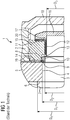
- FIG. 3 shows a transmission 1 according to an embodiment of the present invention.
- the transmission 1 comprises a housing 2 and a shaft 3 arranged therein.
- a toothed wheel 5 fastened on a first shaft shoulder 4, which is a spur wheel in the present case, is secured on both sides by an axial lock 6, 22 against axial displacement secured.
- the first axial securing device 6 forms a fourth shaft shoulder 7 whose diameter D 4 is greater than the diameter D 1 of the first shaft shoulder 4.
- the second axial securing 22 is in the present case designed as an annular component which is screwed on suitable threads on a second shaft shoulder 8 whose diameter D 2 is smaller than the diameter D 1 of the first shaft shoulder 4.
- the second axial securing 22 with tool recesses 23 for receiving a not closer provided turning or screwing provided.
- the tool receiving recesses 23 are provided on the outer circumference of the second axial securing 22 analogously to slot nut grooves.
- axial or radial bores, polygons or the like may be provided, to name just a few examples.
- the facing the gear 5 end face of the second axial securing forms a stop surface for the gear 5.
- the facing the radial-axial slide bearing unit 11 end face of the second axial lock 20 is dimensioned such that the facing thrust bearing of a immediately adjacent arranged radial-axial slide bearing unit 11 completely attached to this.
- this end face defines a running surface 14 for the axial sliding bearing of the radial-axial slide bearing unit 11.
- the radial-axial slide bearing unit 11 is arranged on a third shaft shoulder 12 whose diameter D 3 is smaller than the diameter D 2 of the second shaft shoulder 10.
- Another running surface 15 for the axial sliding bearing of the radial-axial slide bearing unit 11 is presently formed by a further component fastened to the shaft 3, in this case by a thrust bearing 16 secured to the front end of the shaft 3, which has an annular, axially projecting shoulder 17 has, which abuts on the second axial securing 22 remote from the end face of the radial-axial slide bearing unit 11 and defines the sliding surface 15.
- a housing cover 18 is fixed, which positions the radial-axial slide bearing unit 11 via an axially projecting, annular projection 20 in a known manner in the direction of the gear 5 against a housing shoulder 19.
- FIG. 3 illustrated transmission 1 is distinguished from those in the FIGS. 1 and 2 represented known constructions in particular characterized in that it is due to the fact that the second axial securing 22 defined in addition to the axial securing of the gear 5 and the running surface 14 for the axial sliding of the radial-axial slide bearing unit 11, a low-cost construction due to fewer items and only one small footprint for the arrangement of the radial-axial slide bearing unit 11 has.
Landscapes
- Engineering & Computer Science (AREA)
- General Engineering & Computer Science (AREA)
- Mechanical Engineering (AREA)
- General Details Of Gearings (AREA)
- Mounting Of Bearings Or Others (AREA)
- Gear Transmission (AREA)
Abstract
Description
- Die vorliegende Erfindung betrifft ein Getriebe umfassend ein Gehäuse, eine in dem Gehäuse angeordnete Welle, ein auf einem ersten Wellenabsatz angeordnetes Zahnrad, eine erste Axialsicherung, die auf einer ersten Seite des Zahnrads angeordnet ist und dieses axial sichert, eine zweite Axialsicherung, die auf der anderen Seite des Zahnrads auf einem zweiten Wellenabsatz befestigt ist und dieses axial sichert, wobei der Durchmesser des zweiten Wellenabsatzes kleiner als der Durchmesser des ersten Wellenabsatzes ist, eine die Welle in dem Gehäuse lagernde Radial-Axial-Gleitlagereinheit, die auf einem benachbart zum zweiten Wellenabsatz vorgesehenen dritten Wellenabsatz befestigt ist, dessen Durchmesser kleiner als der Durchmesser des zweiten Wellenabsatzes ist, und zumindest ein weiteres an der Welle befestigtes Bauteil, das eine Gleitfläche für das Axialgleitlager der Radial-Axial-Gleitlagereinheit definiert.
- Getriebe der eingangs genannten Art sind im Stand der Technik bereits bekannt. Sie umfassen ein Gehäuse und eine in diesem gelagerte Welle. An einem ersten Wellenabsatz ist ein Zahnrad befestigt, beispielsweise in Form eines Stirnrades. Die Befestigung kann beispielsweise über einen Pressverband, eine Nut-Feder-Verbindung oder dergleichen erfolgen. Zur axialen Sicherung des Zahnrads sind an der Welle eine erste Axialsicherung und eine zweite Axialsicherung vorgesehen, die das Zahnrad zwischen sich aufnehmen. Die erste Axialsicherung kann beispielsweise durch einen vierten Wellenabsatz gebildet sein, dessen Durchmesser größer als der Durchmesser des das Zahnrad aufnehmenden ersten Wellenabsatzes ist. Als zweite Axialsicherung wird meist eine so genannte Nutmutter verwendet, die auf den zweiten Wellenabsatz aufgeschraubt ist und gegen das Zahnrad drückt. DIN 981 unterscheidet verschiedene Bauformen solcher Nutmuttern. Benachbart aber beabstandet zur zweiten Axialsicherung ist zur radialen und axialen Lagerung der Welle eine Radial-Axial-Gleitlagereinheit an dem dritten Wellenabsatz befestigt. Das Axialgleitlager dieser Radial-Axial-Gleitlagereinheit benötigt beidseitig Laufflächen. In diesem Zusammenhang sind zwei Bauformen geläufig.
- Bei der ersten Bauform ist die Radial-Axial-Gleitlagereinheit an ihrer zur ersten Axialsicherung weisenden Stirnseite mit einer sich ausgehend von ihrem Innendurchmesser erstreckenden ringförmigen Aussparung versehen, die es ermöglicht, die Radial-Axial-Gleitlagereinheit derart über die Nutmutter zu schieben, dass die Stirnseite des Zahnrads eine Lauffläche für das Axialgleitlager der Radial-Axial-Gleitlagereinheit bildet. Die andere Lauffläche bildet eine Axiallager-Stützscheibe, die meist am stirnseitigen Ende der Welle befestigt ist. Diese weist einen ringförmigen und axial vorstehenden Absatz auf, der an der dem Zahnrad abgewandten Stirnseite der Radial-Axial-Gleitlagereinheit die Lauffläche bildet.
- Bei der zweiten Bauform wird zwischen der zweiten Axialsicherung und der Radial-Axial-Gleitlagereinheit eine weitere Stützscheibe auf den dritten Wellenabsatz aufgeschoben, die einerseits an der zugewandten Stirnseite des zweiten Wellenabsatzes anliegt und andererseits an der Stirnseite der Radial-Axial-Gleitlagereinheit eine Lauffläche für das Axialgleitlager der Radial-Axial-Gleitlagereinheit bildet. Entsprechend ist die Radial-Axial-Gleitlagereinheit ohne die ringförmige Aussparung ausgeführt. Der übrige Aufbau entspricht dem der ersten Bauform.
- Bei der ersten Bauform wird es als nachteilig angesehen, dass die Herstellung der Radial-Axial-Gleitlagereinheit aufgrund der ringförmigen Ausnehmung teuer ist. Zudem zieht die ringförmige Ausnehmung auch größere Abmessungen als vergleichbare Radial-Axial-Gleitlagereinheiten ohne eine solche Ausnehmung nach sich, was in vielen Fällen nicht wünschenswert ist. Die zweite Bauform ist dahingehend von Nachteil, dass die Stützscheibe ein zusätzliches Element bildet, das zu fertigen und zu montieren ist, was zu größerem Aufwand verbunden ist und auch mit erhöhten Kosten einhergeht.
- Ausgehend von diesem Stand der Technik ist es eine Aufgabe der vorliegenden Erfindung, ein Getriebe der eingangs genannten Art mit einem alternativen Aufbau zu schaffen, der die zuvor beschriebenen Nachteile zumindest teilweise beseitigt.
- Zur Lösung dieser Aufgabe schafft die vorliegende Erfindung ein Getriebe der eingangs genannten Art, das dadurch gekennzeichnet ist, dass die zweite Axialsicherung derart ausgebildet und angeordnet ist, dass sie eine Lauffläche für das Axialgleitlager der Radial-Axial-Gleitlagereinheit definiert. Mit anderen Worten liegt die zweite Axialsicherung, die vorteilhaft einteilig ausgebildet ist, erfindungsgemäß mit ihren Stirnseiten sowohl an dem Zahnrad als auch an der Radial-Axial-Gleitlagereinheit an. Dank einer solchen erfindungsgemäßen zweiten Axialsicherung erübrigen sich Sonderbauformen der Radial-Axial-Gleitlagereinheit ebenso wie der Einsatz einer zusätzlichen, zwischen der zweiten Axialsicherung und der Radial-Axial-Gleitlagereinheit auf der Welle anzuordnenden Stützscheibe zur Bildung einer Gleitfläche, was zu einem einfachen, preiswerten und platzsparenden Aufbau des erfindungsgemäßen Getriebes führt.
- Gemäß einer Ausgestaltung der vorliegenden Erfindung ist das Zahnrad über einen Kegelpressverband an der Welle befestigt. Auf diese Weise wird eine gute und sichere Befestigung des Zahnrads an der Welle sichergestellt.
- Die erste Axialsicherung ist bevorzugt durch einen vierten Wellenabsatz gebildet, dessen Durchmesser größer als der Durchmesser des ersten Wellenabsatzes ist. Entsprechend verringert sich die Gesamtanzahl der Einzelteile des erfindungsgemäßen Getriebes.
- Vorteilhaft ist die zweite Axialsicherung ein ringförmiges Bauteil, das insbesondere über geeignete Gewinde auf den zweiten Wellenabsatz aufgeschraubt und bevorzugt mit Werkzeugaufnahmevertiefungen zur Aufnahme eines Dreh- bzw. Schraubwerkzeugs versehen ist. Mit anderen Worten folgt die Befestigung der zweiten Axialsicherung an der Welle vorteilhaft wie bei einer herkömmlichen Nutmutter, wodurch eine einfache Montage sichergestellt ist.
- Gemäß einer Ausführungsform der vorliegenden Erfindung ist eine zur Radial-Axial-Gleitlagereinheit weisende Stirnfläche der zweiten Axialsicherung derart dimensioniert, dass es für das Axialgleitlager der Radial-Axial-Gleitlagereinheit eine vollständige Lauffläche bildet.
- Bevorzugt ist eine weitere Lauffläche für das Axialgleitlager der Radial-Axial-Gleitlagereinheit durch eine am stirnseitigen Ende der Welle befestigte Axiallager-Stützscheibe gebildet, die einen ringförmigen, axial vorstehenden Absatz aufweist, der an der der zweiten Axialsicherung abgewandten Stirnseite der Radial-Axial-Gleitlagereinheit die Gleitfläche definiert.
- Vorteilhaft ist ein am Gehäuse befestigter Gehäusedeckel vorgesehen, der die Radial-Axial-Gleitlagereinheit in Richtung des Zahnrads gegen einen Gehäuseabsatz positioniert, wodurch eine axiale Sicherung des radial äußeren Endes der Radial-Axial-Gleitlagereinheit realisiert wird.
- Gemäß einer Ausgestaltung der vorliegenden Erfindung ist das Zahnrad ein Stirnrad.
- Weitere Merkmale und Vorteile der vorliegenden Erfindung werden anhand der nachfolgenden Beschreibung eines Getriebes gemäß einer Ausführungsform der vorliegenden Erfindung unter Bezugnahme auf die beiliegende Zeichnung deutlich. Darin ist
- FIG 1
- eine schematische Teilschnittansicht einer ersten Bauform eines bekannten Getriebes;
- FIG 2
- eine schematische Teilschnittansicht einer zweiten Bauform eines bekannten Getriebes; und
- FIG 3
- eine schematische Teilschnittansicht eines Getriebes gemäß einer Ausführungsform der vorliegenden Erfindung.
- Gleiche Bezugsziffern beziehen sich nachfolgend auf funktionsgleiche oder gleichartig ausgebildete Bauteile.
-
FIG 1 zeigt eine erste Bauform eines bekannten Getriebes 1, das ein Gehäuse 2 und eine in dem Gehäuse 2 angeordnete Welle 3 aufweist. Auf einem ersten Wellenabsatz 4, der einen Durchmesser D1 aufweist, ist über einen Pressverband ein Zahnrad 5 befestigt, bei dem es sich vorliegend um ein Stirnrad handelt. Zur axialen Sicherung des Zahnrads 5 sind zwei Axialsicherungen vorgesehen. Die erste Axialsicherung 6 bildet ein vierter Wellenabsatz 7 mit einem Durchmesser D4, der größer als der Durchmesser D1 des ersten Wellenabsatzes 4 ist. Bei der zweiten Axialsicherung 8 handelt es sich um eine handelsübliche Nutmutter 9, die auf einen benachbart zum ersten Wellenabsatz 4 angeordneten zweiten Wellenabsatz 10 geschraubt ist. Ferner umfasst das Getriebe 1 eine die Welle 3 in dem Gehäuse 2 lagernde Radial-Axial-Gleitlagereinheit 11, die auf einem benachbart zum zweiten Wellenabsatz 10 vorgesehenen dritten Wellenabsatz 12 befestigt ist, dessen Durchmesser D3 kleiner als der Durchmesser D2 des zweiten Wellenabsatzes 10 ist. Die Radial-Axial-Gleitlagereinheit 11 weist eine sich ausgehend von ihrem Innendurchmesser erstreckende ringförmige Aussparung 13 auf, die es ermöglicht, die Radial-Axial-Gleitlagereinheit 11 derart über die Nutmutter 9 zu schieben, dass die der Radial-Axial-Gleitlagereinheit 11 zugewandte Stirnfläche des Zahnrads 5 eine Lauffläche 14 für das Axialgleitlager der Radial-Axial-Gleitlagereinheit 11 bildet. Die andere Lauffläche 15 definiert eine Axiallager-Stützscheibe 16, die vorliegend am stirnseitigen Ende der Welle 3 befestigt ist. Die Axiallager-Stützscheibe 16 weist einen ringförmigen und axial vorstehenden Absatz 17 auf, der an der dem Zahnrad 5 abgewandten Stirnseite der Radial-Axial-Gleitlagereinheit 11 anliegt und die Lauffläche 15 bildet. Das Gehäuse 2 umfasst einen an diesem befestigten Gehäusedeckel 18, der die Radial-Axial-Gleitlagereinheit 11 in Richtung des Zahnrads 5 gegen einen Gehäuseabsatz 19 positioniert. Hierzu ist der Gehäusedeckel 16 in bekannter Weise mit einem ringförmigen, axial vorstehenden Vorsprung 20 versehen, der gegen den radial äußeren Bereich der Radial-Axial-Gleitlagereinheit 11 positioniert. -
FIG 2 zeigt eine zweite Bauform eines bekannten Getriebes 1, das sich zum einen dahingehend von der ersten Bauform gemäßFigur 1 unterscheidet, dass die Radial-Axial-Gleitlagereinheit 11 nicht mit der ringförmigen Aussparung 13 versehen ist. Zum anderen ist vorliegend eine weitere Stützscheibe 21 auf den dritten Wellenabsatz 12 aufgeschoben, die einerseits an der zugewandten Stirnseite des zweiten Wellenabsatzes 10 anliegt und andererseits an der Stirnseite der Radial-Axial-Gleitlagereinheit 11 die Lauffläche 14 für das Axialgleitlager der Radial-Axial-Gleitlagereinheit 11 bildet. Im Übrigen entsprechen die in denFiguren 1 und2 dargestellten Bauformen einander. -
FIG 3 zeigt ein Getriebe 1 gemäß einer Ausführungsform der vorliegenden Erfindung. Das Getriebe 1 umfasst ein Gehäuse 2 sowie eine in diesem angeordnete Welle 3. Ein auf einem ersten Wellenabsatz 4 über einen Kegelpressverbund befestigtes Zahnrad 5, bei dem es sich vorliegend um ein Stirnrad handelt, ist beidseitig jeweils durch eine Axialsicherung 6, 22 gegen axiales Verschieben gesichert. Die erste Axialsicherung 6 bildet vorliegend ein vierter Wellenabsatz 7, dessen Durchmesser D4 größer als der Durchmesser D1 des ersten Wellenabsatzes 4 ist. Die zweite Axialsicherung 22 ist vorliegend als ringförmiges Bauteil ausgeführt, das über geeignete Gewinde auf einem zweiten Wellenabsatz 8 aufgeschraubt ist, dessen Durchmesser D2 kleiner als der Durchmesser D1 des ersten Wellenabsatzes 4 ist. Hierzu ist die zweite Axialsicherung 22 mit Werkzeugvertiefungen 23 zur Aufnahme eines nicht näher dargestellten Dreh- bzw. Schraubwerkzeugs versehen. Die Werkzeugaufnahmevertiefungen 23 sind vorliegend analog zu Nutmutter-Nuten am Außenumfang der zweiten Axialsicherung 22 vorgesehen. Alternativ können aber auch axiale oder radiale Bohrungen, Polygone oder dergleichen vorgesehen sein, um nur einige Beispiele zu nennen. Die zum Zahnrad 5 weisende Stirnfläche der zweiten Axialsicherung bildet eine Anschlagfläche für das Zahnrad 5. Die zur Radial-Axial-Gleitlagereinheit 11 weisende Stirnfläche der zweiten Axialsicherung 20 ist derart dimensioniert, dass das zugewandte Axialgleitlager einer unmittelbar benachbart angeordneten Radial-Axial-Gleitlagereinheit 11 vollständig an dieser anliegt. Somit definiert diese Stirnfläche eine Lauffläche 14 für das Axialgleitlager der Radial-Axial-Gleitlagereinheit 11. Die Radial-Axial-Gleitlagereinheit 11 ist auf einem dritten Wellenabsatz 12 angeordnet, dessen Durchmesser D3 kleiner als der Durchmesser D2 des zweiten Wellenabsatzes 10 ist. Eine weitere Lauffläche 15 für das Axialgleitlager der Radial-Axial-Gleitlagereinheit 11 ist vorliegend durch ein weiteres an der Welle 3 befestigtes Bauteil gebildet, vorliegend durch eine am stirnseitigen Ende der Welle 3 befestigte Axiallager-Stützscheibe 16, die einen ringförmigen, axial vorstehenden Absatz 17 aufweist, der an der der zweiten Axialsicherung 22 abgewandten Stirnseite der Radial-Axial-Gleitlagereinheit 11 anliegt und die Gleitfläche 15 definiert. An dem Gehäuse 2 ist ein Gehäusedeckel 18 befestigt, der die Radial-Axial-Gleitlagereinheit 11 über einen axial vorstehenden, ringförmig ausgebildeten Vorsprung 20 in bekannter Weise in Richtung des Zahnrads 5 gegen einen Gehäuseabsatz 19 positioniert. - Das in
FIG 3 dargestellte Getriebe 1 zeichnet sich gegenüber den in denFiguren 1 und2 dargestellten bekannten Bauformen insbesondere dadurch aus, dass es dank der Tatsache, dass die zweite Axialsicherung 22 neben der axialen Sicherung des Zahnrads 5 auch die Lauffläche 14 für das Axialgleitlager der Radial-Axial-Gleitlagereinheit 11 definiert, einen preiswerten Aufbau aufgrund weniger Einzelteile aufweist und nur einen geringen Platzbedarf für die Anordnung der Radial-Axial-Gleitlagereinheit 11 hat. - Obwohl die Erfindung im Detail durch das bevorzugte Ausführungsbeispiel näher illustriert und beschrieben wurde, so ist die Erfindung nicht durch die offenbarten Beispiele eingeschränkt und andere Variationen können vom Fachmann hieraus abgeleitet werden, ohne den Schutzumfang der Erfindung zu verlassen.
Claims (8)
- Getriebe (1) umfassend ein Gehäuse (2), eine in dem Gehäuse (2) angeordnete Welle (3), ein auf einem ersten Wellenabsatz (4) angeordnetes Zahnrad (5), eine erste Axialsicherung (6), die auf einer ersten Seite des Zahnrads (5) angeordnet ist und dieses axial sichert, eine zweite Axialsicherung (22), die auf der anderen Seite des Zahnrads (5) auf einem zweiten Wellenabsatz (10) befestigt ist und dieses axial sichert, wobei der Durchmesser (D2) des zweiten Wellenabsatzes (10) kleiner als der Durchmesser (D1) des ersten Wellenabsatzes (4) ist, eine die Welle (3) in dem Gehäuse (2) lagernde Radial-Axial-Gleitlagereinheit (11), die auf einem benachbart zum zweiten Wellenabsatz (10) vorgesehenen dritten Wellenabsatz (12) befestigt ist, dessen Durchmesser (D3) kleiner als der Durchmesser (D2) des zweiten Wellenabsatzes (10) ist, und zumindest ein weiteres an der Welle (3) befestigtes Bauteil (16), das eine Gleitfläche (15) für das Axialgleitlager der Radial-Axial-Gleitlagereinheit (11) definiert, dadurch gekennzeichnet, dass die zweite Axialsicherung (22) derart ausgebildet und angeordnet ist, dass sie eine Lauffläche (14) für das Axialgleitlager der Radial-Axial-Gleitlagereinheit (11) definiert.
- Getriebe (1) nach Anspruch 1, dadurch gekennzeichnet, dass das Zahnrad (5) über einen Kegelpressverband an der Welle (3) befestigt ist.
- Getriebe (1) nach einem der vorhergehenden Ansprüche, dadurch gekennzeichnet, dass die erste Axialsicherung (6) durch einen vierten Wellenabsatz (7) gebildet ist, dessen Durchmesser (D4) größer als der Durchmesser (D1) des ersten Wellenabsatzes (4) ist.
- Getriebe (1) nach einem der vorhergehenden Ansprüche, dadurch gekennzeichnet, dass die zweite Axialsicherung (22) ein ringförmiges Bauteil ist, das insbesondere über geeignete Gewinde auf den zweiten Wellenabsatz (10) aufgeschraubt und bevorzugt mit Werkzeugaufnahmevertiefungen (23) zur Aufnahme eines Dreh- bzw. Schraubwerkzeugs versehen ist.
- Getriebe (1) nach Anspruch 4, dadurch gekennzeichnet, dass eine zur Radial-Axial-Gleitlagereinheit (11) weisende Stirnfläche der zweiten Axialsicherung (22) derart dimensioniert ist, dass sie für das zugewandte Axialgleitlager der Radial-Axial-Gleitlagereinheit (11) eine vollständige Gleitfläche bildet.
- Getriebe (1) nach einem der vorhergehenden Ansprüche, dadurch gekennzeichnet, dass eine weitere Lauffläche (15) für das Axialgleitlager der Radial-Axial-Gleitlagereinheit (11) durch eine am stirnseitigen Ende der Welle (3) befestigte Axiallager-Stützscheibe (16) gebildet ist, die einen ringförmigen, axial vorstehenden Absatz (17) aufweist, der an der der zweiten Axialsicherung (22) abgewandten Stirnseite der Radial-Axial-Gleitlagereinheit (11) anliegt und die Gleitfläche (15) definiert.
- Getriebe (1) nach einem der vorhergehenden Ansprüche, dadurch gekennzeichnet, dass ein am Gehäuse (2) befestigter Gehäusedeckel (18) vorgesehen ist, der die Radial-Axial-Gleitlagereinheit (11) in Richtung des Zahnrads (5) gegen einen Gehäuseabsatz (19) positioniert.
- Getriebe (1) nach einem der vorhergehenden Ansprüche, dadurch gekennzeichnet, dass das Zahnrad (5) ein Stirnrad ist.
Priority Applications (4)
| Application Number | Priority Date | Filing Date | Title |
|---|---|---|---|
| EP17177773.3A EP3421841B1 (de) | 2017-06-26 | 2017-06-26 | Getriebe |
| ES17177773T ES2781191T3 (es) | 2017-06-26 | 2017-06-26 | Engranaje |
| CN201810527693.8A CN109114197B (zh) | 2017-06-26 | 2018-05-29 | 传动装置 |
| US16/017,440 US10683925B2 (en) | 2017-06-26 | 2018-06-25 | Gear train |
Applications Claiming Priority (1)
| Application Number | Priority Date | Filing Date | Title |
|---|---|---|---|
| EP17177773.3A EP3421841B1 (de) | 2017-06-26 | 2017-06-26 | Getriebe |
Publications (2)
| Publication Number | Publication Date |
|---|---|
| EP3421841A1 true EP3421841A1 (de) | 2019-01-02 |
| EP3421841B1 EP3421841B1 (de) | 2020-01-15 |
Family
ID=59215633
Family Applications (1)
| Application Number | Title | Priority Date | Filing Date |
|---|---|---|---|
| EP17177773.3A Active EP3421841B1 (de) | 2017-06-26 | 2017-06-26 | Getriebe |
Country Status (4)
| Country | Link |
|---|---|
| US (1) | US10683925B2 (de) |
| EP (1) | EP3421841B1 (de) |
| CN (1) | CN109114197B (de) |
| ES (1) | ES2781191T3 (de) |
Families Citing this family (1)
| Publication number | Priority date | Publication date | Assignee | Title |
|---|---|---|---|---|
| CN110566417B (zh) * | 2019-09-12 | 2020-11-24 | 上海电气风电集团股份有限公司 | 滑动主轴承传动链及包括其的双馈风力涡轮机 |
Citations (3)
| Publication number | Priority date | Publication date | Assignee | Title |
|---|---|---|---|---|
| US20020029646A1 (en) * | 2000-09-13 | 2002-03-14 | Aisin Aw Co., Ltd. | Gear supporting structure and hybrid driving unit employing gear supporting structure |
| EP1298354A2 (de) * | 2001-09-28 | 2003-04-02 | JATCO Ltd | Konstruktion einer Keilwellenverbindung für eine Nebenwelle in einem Automatikgetriebe |
| DE102009054595A1 (de) * | 2009-12-14 | 2011-06-16 | Zf Friedrichshafen Ag | Doppelkupplungsgetriebe eines Kraftfahrzeugs |
Family Cites Families (3)
| Publication number | Priority date | Publication date | Assignee | Title |
|---|---|---|---|---|
| DE19633279A1 (de) * | 1996-08-19 | 1998-02-26 | Zahnradfabrik Friedrichshafen | Axiallagerung für Fahrzeuggetriebe mit Schrägverzahnung |
| DE102005046354A1 (de) * | 2005-09-28 | 2007-03-29 | Robert Bosch Gmbh | Getriebe-Antriebseinheit mit einer axialspielfreien Lagerbefestigung, insbesondere zum Verstellen eines beweglichen Teils im Kraftfahrzeug |
| JP5686668B2 (ja) * | 2011-05-23 | 2015-03-18 | 本田技研工業株式会社 | 変速機の軸受固定構造 |
-
2017
- 2017-06-26 ES ES17177773T patent/ES2781191T3/es active Active
- 2017-06-26 EP EP17177773.3A patent/EP3421841B1/de active Active
-
2018
- 2018-05-29 CN CN201810527693.8A patent/CN109114197B/zh active Active
- 2018-06-25 US US16/017,440 patent/US10683925B2/en active Active
Patent Citations (3)
| Publication number | Priority date | Publication date | Assignee | Title |
|---|---|---|---|---|
| US20020029646A1 (en) * | 2000-09-13 | 2002-03-14 | Aisin Aw Co., Ltd. | Gear supporting structure and hybrid driving unit employing gear supporting structure |
| EP1298354A2 (de) * | 2001-09-28 | 2003-04-02 | JATCO Ltd | Konstruktion einer Keilwellenverbindung für eine Nebenwelle in einem Automatikgetriebe |
| DE102009054595A1 (de) * | 2009-12-14 | 2011-06-16 | Zf Friedrichshafen Ag | Doppelkupplungsgetriebe eines Kraftfahrzeugs |
Also Published As
| Publication number | Publication date |
|---|---|
| ES2781191T3 (es) | 2020-08-31 |
| US10683925B2 (en) | 2020-06-16 |
| CN109114197B (zh) | 2021-12-03 |
| CN109114197A (zh) | 2019-01-01 |
| US20180372206A1 (en) | 2018-12-27 |
| EP3421841B1 (de) | 2020-01-15 |
Similar Documents
| Publication | Publication Date | Title |
|---|---|---|
| EP1989467B1 (de) | Zahnradanordnung | |
| DE102014101111A1 (de) | Zahnradanordnung | |
| DE102010011821B4 (de) | Planetenwälzgewindetrieb | |
| DE102011003485A1 (de) | Kugelgewindetrieb und damit ausgestattete Lenkeinrichtung | |
| DE1291586B (de) | Differentialgetriebe mit Reibungskupplungen | |
| DE202010016197U1 (de) | Spielfrei laufendes Zahnrad | |
| DE102013103493A1 (de) | Riemenscheibe und Getriebemutter mit einer solchen Riemenscheibe | |
| DE202011110170U1 (de) | Schneidwerkzeug mit doppelten Kreis-Sägeblättern | |
| DE102013219634A1 (de) | Planetenträger | |
| DE102012005123A1 (de) | Wälzlagerbefestigung und Kugelgewindemutter mit einer solchen | |
| DE102007039733A1 (de) | Lenkeinrichtung mit Anschlagbegrenzung | |
| DE102014117646A1 (de) | Planetengetriebe für ein lenksystem und verfahren zur montage eines planetengetriebes | |
| EP3143294B1 (de) | Vorrichtung zum sichern eines spannelements gegen ungewolltes lösen | |
| DE102013208163A1 (de) | Adapter für eine Ausgangswelle eines Getriebes | |
| DE102016006602A1 (de) | Spielfreies Planetenradgetriebe | |
| EP3421841B1 (de) | Getriebe | |
| DE102016207966A1 (de) | Zahnradanordnung | |
| DE202005008274U1 (de) | Getriebe | |
| DE102015203407A1 (de) | Bauteil zur axialen Sicherung einer Welle-Nabe-Verbindung | |
| DE3047256A1 (de) | "reibungskupplung, insbesondere fuer kraftfahrzeuge" | |
| DE102018131864A1 (de) | Lagereinheit für eine Schneckenwelle eines Lenkgetriebes | |
| DE102010043593A1 (de) | Synchronkörper für eine Synchronisiereinrichtung eines Schaltgetriebes | |
| DE102013000427A1 (de) | Flanschritzel und Herstellungsverfahren dafür sowie spielfreies Stirnrad damit | |
| DE102019112703A1 (de) | Sicherungsring mit Verdrehschutz | |
| DE8110304U1 (de) | Anordnung zur axialen Fixierung von Achsen und Wellen |
Legal Events
| Date | Code | Title | Description |
|---|---|---|---|
| PUAI | Public reference made under article 153(3) epc to a published international application that has entered the european phase |
Free format text: ORIGINAL CODE: 0009012 |
|
| STAA | Information on the status of an ep patent application or granted ep patent |
Free format text: STATUS: THE APPLICATION HAS BEEN PUBLISHED |
|
| AK | Designated contracting states |
Kind code of ref document: A1 Designated state(s): AL AT BE BG CH CY CZ DE DK EE ES FI FR GB GR HR HU IE IS IT LI LT LU LV MC MK MT NL NO PL PT RO RS SE SI SK SM TR |
|
| AX | Request for extension of the european patent |
Extension state: BA ME |
|
| RAP1 | Party data changed (applicant data changed or rights of an application transferred) |
Owner name: FLENDER GMBH |
|
| STAA | Information on the status of an ep patent application or granted ep patent |
Free format text: STATUS: REQUEST FOR EXAMINATION WAS MADE |
|
| 17P | Request for examination filed |
Effective date: 20190702 |
|
| RBV | Designated contracting states (corrected) |
Designated state(s): AL AT BE BG CH CY CZ DE DK EE ES FI FR GB GR HR HU IE IS IT LI LT LU LV MC MK MT NL NO PL PT RO RS SE SI SK SM TR |
|
| RIC1 | Information provided on ipc code assigned before grant |
Ipc: F16H 57/00 20120101AFI20190719BHEP |
|
| GRAP | Despatch of communication of intention to grant a patent |
Free format text: ORIGINAL CODE: EPIDOSNIGR1 |
|
| STAA | Information on the status of an ep patent application or granted ep patent |
Free format text: STATUS: GRANT OF PATENT IS INTENDED |
|
| INTG | Intention to grant announced |
Effective date: 20190916 |
|
| GRAS | Grant fee paid |
Free format text: ORIGINAL CODE: EPIDOSNIGR3 |
|
| GRAA | (expected) grant |
Free format text: ORIGINAL CODE: 0009210 |
|
| STAA | Information on the status of an ep patent application or granted ep patent |
Free format text: STATUS: THE PATENT HAS BEEN GRANTED |
|
| AK | Designated contracting states |
Kind code of ref document: B1 Designated state(s): AL AT BE BG CH CY CZ DE DK EE ES FI FR GB GR HR HU IE IS IT LI LT LU LV MC MK MT NL NO PL PT RO RS SE SI SK SM TR |
|
| REG | Reference to a national code |
Ref country code: CH Ref legal event code: EP Ref country code: GB Ref legal event code: FG4D Free format text: NOT ENGLISH |
|
| REG | Reference to a national code |
Ref country code: IE Ref legal event code: FG4D Free format text: LANGUAGE OF EP DOCUMENT: GERMAN |
|
| REG | Reference to a national code |
Ref country code: DE Ref legal event code: R096 Ref document number: 502017003494 Country of ref document: DE |
|
| REG | Reference to a national code |
Ref country code: AT Ref legal event code: REF Ref document number: 1225429 Country of ref document: AT Kind code of ref document: T Effective date: 20200215 |
|
| REG | Reference to a national code |
Ref country code: SE Ref legal event code: TRGR |
|
| REG | Reference to a national code |
Ref country code: NL Ref legal event code: MP Effective date: 20200115 |
|
| REG | Reference to a national code |
Ref country code: LT Ref legal event code: MG4D |
|
| PG25 | Lapsed in a contracting state [announced via postgrant information from national office to epo] |
Ref country code: RS Free format text: LAPSE BECAUSE OF FAILURE TO SUBMIT A TRANSLATION OF THE DESCRIPTION OR TO PAY THE FEE WITHIN THE PRESCRIBED TIME-LIMIT Effective date: 20200115 Ref country code: FI Free format text: LAPSE BECAUSE OF FAILURE TO SUBMIT A TRANSLATION OF THE DESCRIPTION OR TO PAY THE FEE WITHIN THE PRESCRIBED TIME-LIMIT Effective date: 20200115 Ref country code: NO Free format text: LAPSE BECAUSE OF FAILURE TO SUBMIT A TRANSLATION OF THE DESCRIPTION OR TO PAY THE FEE WITHIN THE PRESCRIBED TIME-LIMIT Effective date: 20200415 Ref country code: PT Free format text: LAPSE BECAUSE OF FAILURE TO SUBMIT A TRANSLATION OF THE DESCRIPTION OR TO PAY THE FEE WITHIN THE PRESCRIBED TIME-LIMIT Effective date: 20200607 Ref country code: NL Free format text: LAPSE BECAUSE OF FAILURE TO SUBMIT A TRANSLATION OF THE DESCRIPTION OR TO PAY THE FEE WITHIN THE PRESCRIBED TIME-LIMIT Effective date: 20200115 |
|
| PG25 | Lapsed in a contracting state [announced via postgrant information from national office to epo] |
Ref country code: IS Free format text: LAPSE BECAUSE OF FAILURE TO SUBMIT A TRANSLATION OF THE DESCRIPTION OR TO PAY THE FEE WITHIN THE PRESCRIBED TIME-LIMIT Effective date: 20200515 Ref country code: LV Free format text: LAPSE BECAUSE OF FAILURE TO SUBMIT A TRANSLATION OF THE DESCRIPTION OR TO PAY THE FEE WITHIN THE PRESCRIBED TIME-LIMIT Effective date: 20200115 Ref country code: GR Free format text: LAPSE BECAUSE OF FAILURE TO SUBMIT A TRANSLATION OF THE DESCRIPTION OR TO PAY THE FEE WITHIN THE PRESCRIBED TIME-LIMIT Effective date: 20200416 Ref country code: BG Free format text: LAPSE BECAUSE OF FAILURE TO SUBMIT A TRANSLATION OF THE DESCRIPTION OR TO PAY THE FEE WITHIN THE PRESCRIBED TIME-LIMIT Effective date: 20200415 Ref country code: HR Free format text: LAPSE BECAUSE OF FAILURE TO SUBMIT A TRANSLATION OF THE DESCRIPTION OR TO PAY THE FEE WITHIN THE PRESCRIBED TIME-LIMIT Effective date: 20200115 |
|
| REG | Reference to a national code |
Ref country code: ES Ref legal event code: FG2A Ref document number: 2781191 Country of ref document: ES Kind code of ref document: T3 Effective date: 20200831 |
|
| REG | Reference to a national code |
Ref country code: DE Ref legal event code: R097 Ref document number: 502017003494 Country of ref document: DE |
|
| PG25 | Lapsed in a contracting state [announced via postgrant information from national office to epo] |
Ref country code: LT Free format text: LAPSE BECAUSE OF FAILURE TO SUBMIT A TRANSLATION OF THE DESCRIPTION OR TO PAY THE FEE WITHIN THE PRESCRIBED TIME-LIMIT Effective date: 20200115 Ref country code: SK Free format text: LAPSE BECAUSE OF FAILURE TO SUBMIT A TRANSLATION OF THE DESCRIPTION OR TO PAY THE FEE WITHIN THE PRESCRIBED TIME-LIMIT Effective date: 20200115 Ref country code: CZ Free format text: LAPSE BECAUSE OF FAILURE TO SUBMIT A TRANSLATION OF THE DESCRIPTION OR TO PAY THE FEE WITHIN THE PRESCRIBED TIME-LIMIT Effective date: 20200115 Ref country code: RO Free format text: LAPSE BECAUSE OF FAILURE TO SUBMIT A TRANSLATION OF THE DESCRIPTION OR TO PAY THE FEE WITHIN THE PRESCRIBED TIME-LIMIT Effective date: 20200115 Ref country code: DK Free format text: LAPSE BECAUSE OF FAILURE TO SUBMIT A TRANSLATION OF THE DESCRIPTION OR TO PAY THE FEE WITHIN THE PRESCRIBED TIME-LIMIT Effective date: 20200115 Ref country code: EE Free format text: LAPSE BECAUSE OF FAILURE TO SUBMIT A TRANSLATION OF THE DESCRIPTION OR TO PAY THE FEE WITHIN THE PRESCRIBED TIME-LIMIT Effective date: 20200115 Ref country code: SM Free format text: LAPSE BECAUSE OF FAILURE TO SUBMIT A TRANSLATION OF THE DESCRIPTION OR TO PAY THE FEE WITHIN THE PRESCRIBED TIME-LIMIT Effective date: 20200115 |
|
| PLBE | No opposition filed within time limit |
Free format text: ORIGINAL CODE: 0009261 |
|
| STAA | Information on the status of an ep patent application or granted ep patent |
Free format text: STATUS: NO OPPOSITION FILED WITHIN TIME LIMIT |
|
| 26N | No opposition filed |
Effective date: 20201016 |
|
| PG25 | Lapsed in a contracting state [announced via postgrant information from national office to epo] |
Ref country code: MC Free format text: LAPSE BECAUSE OF FAILURE TO SUBMIT A TRANSLATION OF THE DESCRIPTION OR TO PAY THE FEE WITHIN THE PRESCRIBED TIME-LIMIT Effective date: 20200115 |
|
| REG | Reference to a national code |
Ref country code: CH Ref legal event code: PL |
|
| PG25 | Lapsed in a contracting state [announced via postgrant information from national office to epo] |
Ref country code: SI Free format text: LAPSE BECAUSE OF FAILURE TO SUBMIT A TRANSLATION OF THE DESCRIPTION OR TO PAY THE FEE WITHIN THE PRESCRIBED TIME-LIMIT Effective date: 20200115 Ref country code: PL Free format text: LAPSE BECAUSE OF FAILURE TO SUBMIT A TRANSLATION OF THE DESCRIPTION OR TO PAY THE FEE WITHIN THE PRESCRIBED TIME-LIMIT Effective date: 20200115 |
|
| PG25 | Lapsed in a contracting state [announced via postgrant information from national office to epo] |
Ref country code: LU Free format text: LAPSE BECAUSE OF NON-PAYMENT OF DUE FEES Effective date: 20200626 |
|
| REG | Reference to a national code |
Ref country code: BE Ref legal event code: MM Effective date: 20200630 |
|
| PG25 | Lapsed in a contracting state [announced via postgrant information from national office to epo] |
Ref country code: CH Free format text: LAPSE BECAUSE OF NON-PAYMENT OF DUE FEES Effective date: 20200630 Ref country code: LI Free format text: LAPSE BECAUSE OF NON-PAYMENT OF DUE FEES Effective date: 20200630 Ref country code: IE Free format text: LAPSE BECAUSE OF NON-PAYMENT OF DUE FEES Effective date: 20200626 |
|
| REG | Reference to a national code |
Ref country code: DE Ref legal event code: R082 Ref document number: 502017003494 Country of ref document: DE Representative=s name: MICHALSKI HUETTERMANN & PARTNER PATENTANWAELTE, DE |
|
| PG25 | Lapsed in a contracting state [announced via postgrant information from national office to epo] |
Ref country code: BE Free format text: LAPSE BECAUSE OF NON-PAYMENT OF DUE FEES Effective date: 20200630 |
|
| PG25 | Lapsed in a contracting state [announced via postgrant information from national office to epo] |
Ref country code: TR Free format text: LAPSE BECAUSE OF FAILURE TO SUBMIT A TRANSLATION OF THE DESCRIPTION OR TO PAY THE FEE WITHIN THE PRESCRIBED TIME-LIMIT Effective date: 20200115 Ref country code: MT Free format text: LAPSE BECAUSE OF FAILURE TO SUBMIT A TRANSLATION OF THE DESCRIPTION OR TO PAY THE FEE WITHIN THE PRESCRIBED TIME-LIMIT Effective date: 20200115 Ref country code: CY Free format text: LAPSE BECAUSE OF FAILURE TO SUBMIT A TRANSLATION OF THE DESCRIPTION OR TO PAY THE FEE WITHIN THE PRESCRIBED TIME-LIMIT Effective date: 20200115 |
|
| PG25 | Lapsed in a contracting state [announced via postgrant information from national office to epo] |
Ref country code: MK Free format text: LAPSE BECAUSE OF FAILURE TO SUBMIT A TRANSLATION OF THE DESCRIPTION OR TO PAY THE FEE WITHIN THE PRESCRIBED TIME-LIMIT Effective date: 20200115 Ref country code: AL Free format text: LAPSE BECAUSE OF FAILURE TO SUBMIT A TRANSLATION OF THE DESCRIPTION OR TO PAY THE FEE WITHIN THE PRESCRIBED TIME-LIMIT Effective date: 20200115 |
|
| PGFP | Annual fee paid to national office [announced via postgrant information from national office to epo] |
Ref country code: SE Payment date: 20220620 Year of fee payment: 6 Ref country code: IT Payment date: 20220627 Year of fee payment: 6 Ref country code: GB Payment date: 20220627 Year of fee payment: 6 |
|
| PGFP | Annual fee paid to national office [announced via postgrant information from national office to epo] |
Ref country code: FR Payment date: 20220628 Year of fee payment: 6 |
|
| REG | Reference to a national code |
Ref country code: AT Ref legal event code: MM01 Ref document number: 1225429 Country of ref document: AT Kind code of ref document: T Effective date: 20220626 |
|
| PG25 | Lapsed in a contracting state [announced via postgrant information from national office to epo] |
Ref country code: AT Free format text: LAPSE BECAUSE OF NON-PAYMENT OF DUE FEES Effective date: 20220626 |
|
| REG | Reference to a national code |
Ref country code: SE Ref legal event code: EUG |
|
| GBPC | Gb: european patent ceased through non-payment of renewal fee |
Effective date: 20230626 |
|
| PG25 | Lapsed in a contracting state [announced via postgrant information from national office to epo] |
Ref country code: GB Free format text: LAPSE BECAUSE OF NON-PAYMENT OF DUE FEES Effective date: 20230626 |
|
| PG25 | Lapsed in a contracting state [announced via postgrant information from national office to epo] |
Ref country code: SE Free format text: LAPSE BECAUSE OF NON-PAYMENT OF DUE FEES Effective date: 20230627 Ref country code: FR Free format text: LAPSE BECAUSE OF NON-PAYMENT OF DUE FEES Effective date: 20230630 |
|
| PG25 | Lapsed in a contracting state [announced via postgrant information from national office to epo] |
Ref country code: IT Free format text: LAPSE BECAUSE OF NON-PAYMENT OF DUE FEES Effective date: 20230626 |
|
| PGFP | Annual fee paid to national office [announced via postgrant information from national office to epo] |
Ref country code: DE Payment date: 20250625 Year of fee payment: 9 |
|
| PGFP | Annual fee paid to national office [announced via postgrant information from national office to epo] |
Ref country code: ES Payment date: 20250728 Year of fee payment: 9 |