EP3421331B1 - Système d'un élément structurel renforcé d'un véhicule automobile - Google Patents
Système d'un élément structurel renforcé d'un véhicule automobile Download PDFInfo
- Publication number
- EP3421331B1 EP3421331B1 EP17178832.6A EP17178832A EP3421331B1 EP 3421331 B1 EP3421331 B1 EP 3421331B1 EP 17178832 A EP17178832 A EP 17178832A EP 3421331 B1 EP3421331 B1 EP 3421331B1
- Authority
- EP
- European Patent Office
- Prior art keywords
- adhesive
- side wall
- reinforcing element
- wall
- structural element
- Prior art date
- Legal status (The legal status is an assumption and is not a legal conclusion. Google has not performed a legal analysis and makes no representation as to the accuracy of the status listed.)
- Active
Links
- 239000000853 adhesive Substances 0.000 claims description 85
- 230000001070 adhesive effect Effects 0.000 claims description 85
- 230000003014 reinforcing effect Effects 0.000 claims description 48
- 239000000463 material Substances 0.000 claims description 13
- 238000007789 sealing Methods 0.000 claims description 5
- 229920002430 Fibre-reinforced plastic Polymers 0.000 claims description 2
- FYYHWMGAXLPEAU-UHFFFAOYSA-N Magnesium Chemical compound [Mg] FYYHWMGAXLPEAU-UHFFFAOYSA-N 0.000 claims description 2
- 229910052782 aluminium Inorganic materials 0.000 claims description 2
- XAGFODPZIPBFFR-UHFFFAOYSA-N aluminium Chemical compound [Al] XAGFODPZIPBFFR-UHFFFAOYSA-N 0.000 claims description 2
- 239000011151 fibre-reinforced plastic Substances 0.000 claims description 2
- 229910052749 magnesium Inorganic materials 0.000 claims description 2
- 239000011777 magnesium Substances 0.000 claims description 2
- 239000004033 plastic Substances 0.000 claims description 2
- 229920003023 plastic Polymers 0.000 claims description 2
- 239000004411 aluminium Substances 0.000 claims 1
- 230000002787 reinforcement Effects 0.000 description 61
- 229910052751 metal Inorganic materials 0.000 description 8
- 239000002184 metal Substances 0.000 description 8
- 239000010410 layer Substances 0.000 description 6
- 238000010276 construction Methods 0.000 description 4
- 239000012790 adhesive layer Substances 0.000 description 3
- 239000002390 adhesive tape Substances 0.000 description 3
- 230000000694 effects Effects 0.000 description 3
- 239000000835 fiber Substances 0.000 description 3
- 239000007788 liquid Substances 0.000 description 3
- 239000000243 solution Substances 0.000 description 3
- 230000005540 biological transmission Effects 0.000 description 2
- 239000003292 glue Substances 0.000 description 2
- 239000003973 paint Substances 0.000 description 2
- 239000004952 Polyamide Substances 0.000 description 1
- 230000006399 behavior Effects 0.000 description 1
- 230000015572 biosynthetic process Effects 0.000 description 1
- 239000004918 carbon fiber reinforced polymer Substances 0.000 description 1
- 239000011152 fibreglass Substances 0.000 description 1
- 238000005187 foaming Methods 0.000 description 1
- 230000006870 function Effects 0.000 description 1
- 238000002347 injection Methods 0.000 description 1
- 239000007924 injection Substances 0.000 description 1
- 230000033001 locomotion Effects 0.000 description 1
- 239000000203 mixture Substances 0.000 description 1
- 238000010422 painting Methods 0.000 description 1
- 229920002647 polyamide Polymers 0.000 description 1
- 230000003313 weakening effect Effects 0.000 description 1
Images


Classifications
-
- B—PERFORMING OPERATIONS; TRANSPORTING
- B62—LAND VEHICLES FOR TRAVELLING OTHERWISE THAN ON RAILS
- B62D—MOTOR VEHICLES; TRAILERS
- B62D25/00—Superstructure or monocoque structure sub-units; Parts or details thereof not otherwise provided for
- B62D25/04—Door pillars ; windshield pillars
-
- B—PERFORMING OPERATIONS; TRANSPORTING
- B32—LAYERED PRODUCTS
- B32B—LAYERED PRODUCTS, i.e. PRODUCTS BUILT-UP OF STRATA OF FLAT OR NON-FLAT, e.g. CELLULAR OR HONEYCOMB, FORM
- B32B7/00—Layered products characterised by the relation between layers; Layered products characterised by the relative orientation of features between layers, or by the relative values of a measurable parameter between layers, i.e. products comprising layers having different physical, chemical or physicochemical properties; Layered products characterised by the interconnection of layers
- B32B7/04—Interconnection of layers
- B32B7/12—Interconnection of layers using interposed adhesives or interposed materials with bonding properties
-
- B—PERFORMING OPERATIONS; TRANSPORTING
- B62—LAND VEHICLES FOR TRAVELLING OTHERWISE THAN ON RAILS
- B62D—MOTOR VEHICLES; TRAILERS
- B62D25/00—Superstructure or monocoque structure sub-units; Parts or details thereof not otherwise provided for
- B62D25/02—Side panels
-
- B—PERFORMING OPERATIONS; TRANSPORTING
- B62—LAND VEHICLES FOR TRAVELLING OTHERWISE THAN ON RAILS
- B62D—MOTOR VEHICLES; TRAILERS
- B62D29/00—Superstructures, understructures, or sub-units thereof, characterised by the material thereof
- B62D29/001—Superstructures, understructures, or sub-units thereof, characterised by the material thereof characterised by combining metal and synthetic material
- B62D29/005—Superstructures, understructures, or sub-units thereof, characterised by the material thereof characterised by combining metal and synthetic material preformed metal and synthetic material elements being joined together, e.g. by adhesives
-
- B—PERFORMING OPERATIONS; TRANSPORTING
- B62—LAND VEHICLES FOR TRAVELLING OTHERWISE THAN ON RAILS
- B62D—MOTOR VEHICLES; TRAILERS
- B62D29/00—Superstructures, understructures, or sub-units thereof, characterised by the material thereof
- B62D29/008—Superstructures, understructures, or sub-units thereof, characterised by the material thereof predominantly of light alloys, e.g. extruded
-
- B—PERFORMING OPERATIONS; TRANSPORTING
- B62—LAND VEHICLES FOR TRAVELLING OTHERWISE THAN ON RAILS
- B62D—MOTOR VEHICLES; TRAILERS
- B62D29/00—Superstructures, understructures, or sub-units thereof, characterised by the material thereof
- B62D29/04—Superstructures, understructures, or sub-units thereof, characterised by the material thereof predominantly of synthetic material
- B62D29/048—Connections therefor, e.g. joints
-
- B—PERFORMING OPERATIONS; TRANSPORTING
- B32—LAYERED PRODUCTS
- B32B—LAYERED PRODUCTS, i.e. PRODUCTS BUILT-UP OF STRATA OF FLAT OR NON-FLAT, e.g. CELLULAR OR HONEYCOMB, FORM
- B32B2605/00—Vehicles
-
- B—PERFORMING OPERATIONS; TRANSPORTING
- B60—VEHICLES IN GENERAL
- B60R—VEHICLES, VEHICLE FITTINGS, OR VEHICLE PARTS, NOT OTHERWISE PROVIDED FOR
- B60R13/00—Elements for body-finishing, identifying, or decorating; Arrangements or adaptations for advertising purposes
- B60R13/08—Insulating elements, e.g. for sound insulation
- B60R13/0815—Acoustic or thermal insulation of passenger compartments
Definitions
- the invention relates to a system of a reinforced structural element of a motor vehicle.
- the invention relates to a system comprising a structural element, a reinforcing element and an adhesive.
- components such as bodies and / or frames of means of locomotion, in particular of motor vehicles, have structures with cavities in order to enable lightweight constructions. It is often desirable to strengthen these cavities, and thus the component, significantly, while maintaining the low weight.
- reinforcing elements are therefore used to reinforce cavities.
- a body of an automobile is shown schematically.
- the body 10 has different structures with cavities, such as the A-pillar 11, the B-pillar 12, the C-pillar 13 and the roof frame 14.
- Such and other cavities or structures in the bodies of motor vehicles are usually reinforced with reinforcing elements which have a foamable adhesive for bonding the reinforcing element in the structural component.
- a disadvantage of such known solutions is that for areas with particularly high requirements in terms of a reinforced structure, such as the A-pillar or the roof frame, a reinforcing effect that can be achieved with such known solutions is not sufficient.
- a mechanical reinforcement effect that is as high as possible is desirable, particularly for components that take on important functions in the event of very high load cases, such as those that occur in accidents.
- EP2154052A1 discloses a structural reinforcement system in which a rigid support has an insert, the support being secured in a structural element with the aid of an expandable material.
- the insert can be made of metal, for example.
- a system of a reinforced structural element of a motor vehicle comprising: a structural element which comprises a first sheet metal and a second sheet metal, the sheets being connected to one another at a first joint and a second joint, and the Sheet metal in the area between the first joint and the second joint form an elongated cavity, and the second sheet in the area between the first joint and the second joint has a bulge with a first leg, which is arranged at the first joint, and with a second Leg, which is arranged at the second joint, has; a reinforcing element which comprises a first side wall, a second side wall and a connecting wall connecting the side walls, and which is arranged in the cavity of the structural element; and adhesive which bonds the reinforcement element to the structural element; wherein the first side wall of the reinforcement element is arranged in the area of the first joint and the second side wall of the reinforcement element is arranged in the area of the second leg of the second sheet, so that a force acting on the first joint in the direction of the reinforcement element through the
- a key idea of the present invention is that the reinforcement element absorbs the load in the right place in the load case (here at the first joint) and distributed more widely in the structural element (here on the second leg of the second sheet).
- a reinforcement element with a reduced volume and therefore weight-optimized can be produced, which has the desired mechanical properties without significantly increasing the weight of the component.
- the structural element is part of an A-pillar or a roof frame of a body of a motor vehicle.
- the reinforcement element is at least partially constructed from plastic, fiber-reinforced plastic, aluminum or magnesium.
- the reinforcement element is at least partially constructed from glass fiber reinforced plastic or from carbon fiber reinforced plastic.
- glass fiber reinforced plastic or from carbon fiber reinforced plastic.
- continuous fibers, short fibers or long fibers can be used.
- the reinforcing element is at least partially made of polyamide, in particular of PA6 or PA6.6.
- first side wall and the second side wall of the reinforcement element extend on the same side of the connecting wall, or the first side wall and the second side wall of the reinforcing element extend on different sides of the connecting wall.
- the connecting wall of the reinforcement element transmits the force from the first side wall to the second side wall and thereby from the first joint to the second leg of the second sheet metal.
- the reinforcing element can have an essentially C- or U-shaped cross section so that the first and second side walls extend on the same side of the connecting wall, or the reinforcing element can have an essentially Z or S-shaped cross section so that the first and second side walls extend on different sides of the connecting wall.
- a suitable variant can be selected here depending on the geometry of the cavity and the requirements of the load case.
- a wall thickness of the first side wall is greater than a wall thickness of the second side wall.
- This exemplary embodiment is based on the knowledge that the first side wall experiences a greater load than the second side wall when there is a load.
- the system as a whole can thus be reinforced by the targeted reinforcement of the first side wall without the weight being unnecessarily increased.
- a wall thickness of the first side wall is from 2 to 8 mm, preferably from 3 to 5 mm, and a wall thickness of the second side wall is from 1 to 4 mm, preferably from 2 to 3 mm.
- the reinforcement element comprises ribs which are oriented essentially orthogonally to a longitudinal axis of the reinforcement element and which connect the first side wall and the second side wall to one another.
- Essentially orthogonal to the longitudinal axis means in this context that the ribs can also be arranged orthogonally to the longitudinal axis with small deviations, since, for example, the side walls of the reinforcement element do not necessarily run exactly parallel to one another over an entire length, so that the ribs do not always run are arranged exactly orthogonally to the longitudinal axis.
- a distance between adjacent ribs, measured along the longitudinal axis of the reinforcement element is from 5 to 50 mm, preferably from 8 to 40 mm, particularly preferably from 10 to 30 mm.
- the provision of ribs in the interior of the reinforcement element has the advantage that a force transmission from the first side wall to the second side wall can be further improved.
- the reinforcement element has a length, measured in the direction of the longitudinal axis of the reinforcement element, from 200 to 1200 mm, preferably from 300 to 1100 mm, particularly preferably from 500 to 800 mm.
- the first side wall and / or the second side wall has a width, each measured transversely to the longitudinal axis of the reinforcing element, of 10 to 50 mm, preferably 10 to 40 mm, particularly preferably 10 to 30 mm.
- the formation of the reinforcement element with the dimensions specified above has the advantage that particularly A-pillars or roof frames can be reinforced in an ideal way. Tests have shown that a width of the first and the second side wall of approximately 18 mm is sufficient to ensure the transmission of the force described here from the first joint to the second leg of the second sheet. It is therefore not necessary to use a larger reinforcing element and thus a higher weight.
- the adhesive has a layer thickness of 0.3 to 7 mm, preferably 0.5 to 5 mm, particularly preferably 1 to 3 mm.
- the adhesive has a layer thickness of 0.3 to 7 mm, preferably 0.5 to 5 mm, particularly preferably 1 to 3 mm.
- the glue is a non-expandable glue.
- non-expandable means behavior of a material in which the volume of the material does not change by more than 10%.
- Materials such as adhesives, for example, which expand or contract slightly during curing, for example, are also understood as non-expandable materials.
- expansion rate is understood to mean the volume which is added in the event of an expansion relative to the existing volume.
- an expansion rate of 100% means a doubling of the volume during the expansion.
- the adhesive is a tape adhesive, a shape memory adhesive, an injectable adhesive, an injection molded adhesive, or an extruded adhesive.
- Such an adhesive tape adhesive has the advantage that it simplifies handling of the adhesive application. In particular, it is easy to ensure that the adhesive volume is metered in the case of adhesive tape adhesives.
- the adhesive is a shape memory adhesive.
- Shape memory adhesives such as those used in documents WO 2011/117398 and WO 2011/117402 are described, for example, can be applied to the reinforcement element and then brought into a tensioned shape. In this tensioned form, the reinforcing element with the adhesive is brought into the cavity. The adhesive can be returned to its original shape by applying heat, and the adhesive closes a gap between the reinforcement element and the structural element.
- shape memory adhesives are that there is a gap between the reinforcement element and the structural element, for example to paint the structural element, and that at the same time a bond with very good mechanical properties can be achieved because the shape memory adhesive does not have to be foamed.
- the adhesive is an injectable adhesive.
- a system with injected adhesives is in document WO 2008/077944 shown.
- the reinforcing element is first arranged in the structural element, and then the liquid adhesive is introduced into the space between the reinforcing element and the structural element.
- the adhesive is an injection-molded adhesive.
- the adhesive has an expansion rate of less than 400%, preferably of less than 300%, particularly preferably of less than 250%.
- the adhesive is an extruded adhesive.
- a system with such an extruded adhesive is, for example, in US Pat WO 2014/124924 described.
- extruded adhesives are, in particular, that they do not have to overcome a gap between the reinforcement element and the structural element, and that consequently no foaming and thus mechanical weakening of the adhesive is necessary.
- adhesives available under the trade name SikaPower® can be used as injectable adhesives.
- a cross section of the reinforcement element is less than 70%, preferably less than 60%, particularly preferably less than 50% of a cross section of the structural element, measured at the same point.
- a reinforcing element with a small cross-section enables a weight-optimized component to be achieved.
- a liquid for dip painting the body can better circulate.
- an outer cavity which is free of the reinforcing element and adhesive is at least 25%, preferably at least 30%, particularly preferably at least 35% of a cross section of the structural element, measured at the same point.
- an outer cavity which is free of the reinforcing element and adhesive is at least 25%, preferably at least 30%, particularly preferably at least 35% of a cross section of the structural element, measured at the same point.
- the connecting wall of the reinforcement element is at least partially free of adhesive and / or the adhesive on the first side wall is not connected to the adhesive on the second side wall.
- Arranging the adhesive on the first side wall and on the second side wall and at least partially not on the connecting wall has the advantage that the adhesive is used specifically at those locations where a connection between reinforcing element and structural element effectively contributes to the mechanical properties of the component .
- the provision of two separate adhesive areas has the advantage that application of the adhesive is simplified, in particular in the case of adhesive tape adhesives and in the case of adhesives that are extruded on.
- a first adhesive is arranged on the first side wall and a second adhesive is arranged on the second side wall.
- the first adhesive and the second adhesive are identical adhesives.
- the first adhesive and the second adhesive are different adhesives.
- the first adhesive can have a different expansion rate or a different composition than the second adhesive.
- a sealing or soundproofing material is arranged on the connecting wall and / or on the front wall and / or on the rear wall of the reinforcing element.
- this sealing or soundproofing material has an expansion rate of more than 500%, preferably of more than 1000%, particularly preferably of more than 1500%.
- sealing or soundproofing material at the points mentioned has the advantage that the structural element with an element arranged therein can be reinforced and sealed at the same time.
- an expandable material which is available under the trade name SikaBaffle® 450, can be used as a sealing or soundproofing material.
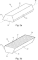
- Fig. 2a an exemplary system 1 of a reinforced structural element of a motor vehicle is shown, only the second sheet metal 5 of the structural element being shown in this illustration.
- the first sheet metal is omitted from this illustration so that the reinforcement element 20 is visible.
- the elongated reinforcing element 20 is arranged in the elongated cavity of the structural element.
- the reinforcement element 20 has a front and a rear wall 24.
- the reinforcement element 20 has ribs 17, which are oriented essentially orthogonally to the longitudinal axis of the reinforcement element and also connect the first side wall 21 to the second side wall 22.
- the ribs 17 in areas of the reinforcement element 20 in which the side walls do not run parallel to one another can differ slightly in their arrangement relative to the longitudinal axis, as is the case here in a region of a lower end of the reinforcement element 20 .
- an exemplary reinforcement element 20 is shown without a structural element.
- the reinforcement element 20 has a first side wall 21 and a second side wall 22, and a connecting wall 23 connecting the side walls.
- the reinforcement element 20 also has a front and a rear wall 24 Connecting wall 23 are covered.
- FIG. 3a Another exemplary schematic reinforcement element 20 is shown.
- the connecting wall 23 of the reinforcing element 20 directed upwards
- Figure 3b the connecting wall 23 of the reinforcing element 20 is directed downwards.
- the reinforcement element 20 has a longitudinal axis 26 and a first side wall 21 and a second side wall 22.
- the first side wall 21 has a bend so that the first side wall 21 does not lie in one plane.
- the reinforcement element 20 also has a front and a rear wall 24 as well as ribs 17. Again, the ribs 17 are arranged essentially orthogonally to the longitudinal axis 26 of the reinforcement element 20.
- FIG. 4 an exemplary cross section of a system 1 of a reinforced structural element 2 is shown.
- the structural element 2 comprises a first sheet 4 and a second sheet 5.
- the first sheet 4 and the second sheet 5 are connected to one another at a first joint 6 and at a second joint 7. Between the first joint 6 and the second joint 7, the first sheet 4 and the second sheet 5 form a cavity 3.
- the second sheet 5 has a bulge, with a first leg 5.1, which is arranged at the first joint 6, and a second leg 5.2, which is arranged at the second joint 7.
- the reinforcing element 20 is now arranged in the cavity 3 of this structural element 2.
- the reinforcement element 20 in turn has a connecting wall 23 as well as a first side wall 21 and a second side wall 22.
- the first side wall 21 is arranged in the area of the first joint 6, and the second side wall 22 is arranged in the area of the second leg 5.2 of the second sheet 5 .
- the first side wall 21 and the second side wall 22 are each glued to the structural element 2 with adhesive 8.
- the first side wall 21 can only be glued to the second sheet 5, or else to the first sheet 4 and to the second sheet 5.
- the first side wall 21 is arranged in the area of the first joint 6 and is only glued to the second sheet 5.
- the cavity 3 of the structural element 2 has an outer cavity 3.1 and an inner cavity 3.2, which are each free from the reinforcement element 20 and from the adhesive 8, or are free from the cross section 25 of the reinforcement element 20.
- These free cavities in particular the outer one Cavity 3.1, simplify the circulation of a paint liquid when the body is dip-painted.
- a lighter component is made possible by reducing the cross-sectional area 25 of the reinforcing element 20.
- the first side wall 21 is arranged in the area of the first joint 6 and is glued to both the first sheet 4 and to the second sheet 5.
Claims (14)
- Système (1) d'un élément structural renforcé (2) d'un véhicule automobile, le système (1) comprenant :un élément structural (2), qui comprend une première tôle (4) et une deuxième tôle (5), les tôles (4, 5) étant reliées l'une à l'autre à un premier point de jonction (6) et à un deuxième point de jonction (7), et les tôles (4, 5) formant dans la zone entre le premier point de jonction (6) et le deuxième point de jonction (7) une chambre creuse allongée (3), et la deuxième tôle (5) ayant dans la zone entre le premier point de jonction (6) et le deuxième point de jonction (7) un bombement muni d'une première branche (5.1), qui est agencée au niveau du premier point de jonction (6), et muni d'une deuxième branche (5.2), qui est agencée au niveau du deuxième point de jonction (7) ;un élément de renforcement (20), qui comprend une première paroi latérale (21), une deuxième paroi latérale (22) et une paroi de liaison (23) reliant les parois latérales (21, 22), et qui est agencé dans la chambre creuse (3) de l'élément structural (2) ; etun adhésif (8), qui colle l'élément de renforcement (20) à l'élément structural (2) ;dans lequel la première paroi latérale (21) de l'élément de renforcement (20) est agencée dans la zone du premier point de jonction (6) et la deuxième paroi latérale (22) de l'élément de renforcement (20) est agencée dans la zone de la deuxième branche (5.2) de la deuxième tôle (5), de telle sorte qu'une force (15) agissant sur le premier point de jonction (6) en direction de l'élément de renforcement (20) soit transférée par l'élément de renforcement (20) majoritairement à la deuxième branche (5.2) de la deuxième tôle (5),caractérisé en ce que l'adhésif (8) est un adhésif non expansible.
- Système (1) selon la revendication 1, dans lequel l'élément structural (2) est un constituant d'un montant A (11) ou d'un cadre de toit (14) d'une carrosserie (10) d'un véhicule automobile.
- Système (1) selon l'une quelconque des revendications 1 ou 2, dans lequel l'élément de renforcement (20) est formé au moins partiellement en matière plastique renforcée par des fibres ou en matière plastique ou en aluminium ou en magnésium.
- Système (1) selon l'une quelconque des revendications précédentes, dans lequel la première paroi latérale (21) et la deuxième paroi latérale (22) de l'élément de renforcement (20) s'étendent sur un même côté de la paroi de liaison (23), ou dans lequel la première paroi latérale (21) et la deuxième paroi latérale (22) de l'élément de renforcement (20) s'étendent sur des côtés différents de la paroi de liaison (23).
- Système (1) selon l'une quelconque des revendications précédentes, dans lequel une épaisseur de paroi de la première paroi latérale (21) est supérieure à une épaisseur de paroi de la deuxième paroi latérale (22).
- Système (1) selon l'une quelconque des revendications précédentes, dans lequel une largeur de la première paroi latérale (21) et/ou de la deuxième paroi latérale (22), mesurée perpendiculairement à un axe longitudinal (26) de l'élément de renforcement (20), est de 10 à 35 mm.
- Système (1) selon l'une quelconque des revendications précédentes, dans lequel l'élément de renforcement (20) comprend des nervures (17), qui sont orientées essentiellement orthogonalement par rapport à un axe longitudinal (26) de l'élément de renforcement (20), et qui relient la première paroi latérale (21) et la deuxième paroi latérale (22) l'une à l'autre.
- Système (1) selon l'une quelconque des revendications précédentes, dans lequel l'élément de renforcement (20) a une longueur, mesurée dans la direction de l'axe longitudinal (26) de l'élément de renforcement (20), de 200 à 1 200 mm.
- Système (1) selon l'une quelconque des revendications précédentes, dans lequel l'adhésif (8) a une épaisseur de couche de 0,3 à 7 mm.
- Système (1) selon l'une quelconque des revendications précédentes, dans lequel l'adhésif (8) est un adhésif à bande adhésive, un adhésif à mémoire de forme, un adhésif injectable ou un adhésif extrudé.
- Système (1) selon l'une quelconque des revendications précédentes, dans lequel une section transversale de l'élément de renforcement (20) est de moins de 70 % d'une section transversale de l'élément structural (2), mesurée au même point.
- Système (1) selon l'une quelconque des revendications précédentes, dans lequel une chambre creuse extérieure (3.1), qui est exempte d'élément de renforcement (20) et d'adhésif (8), est d'au moins 25 % d'une section transversale de l'élément structural (2), mesurée au même point.
- Système (1) selon l'une quelconque des revendications précédentes, dans lequel la paroi de liaison (23) de l'élément de renforcement (20) est au moins partiellement exempte d'adhésif (8) et/ou dans lequel l'adhésif (8) sur la première paroi latérale (21) n'est pas relié à l'adhésif (8) sur la deuxième paroi latérale (22).
- Système (1) selon l'une quelconque des revendications précédentes, dans lequel un matériau d'étanchéification ou d'isolation acoustique est agencé sur la paroi de liaison (23) et/ou sur la paroi avant (24) et/ou sur la paroi arrière (24).
Priority Applications (2)
| Application Number | Priority Date | Filing Date | Title |
|---|---|---|---|
| EP17178832.6A EP3421331B1 (fr) | 2017-06-29 | 2017-06-29 | Système d'un élément structurel renforcé d'un véhicule automobile |
| US16/023,290 US10569808B2 (en) | 2017-06-29 | 2018-06-29 | Motor vehicle reinforced structural element system |
Applications Claiming Priority (1)
| Application Number | Priority Date | Filing Date | Title |
|---|---|---|---|
| EP17178832.6A EP3421331B1 (fr) | 2017-06-29 | 2017-06-29 | Système d'un élément structurel renforcé d'un véhicule automobile |
Publications (2)
| Publication Number | Publication Date |
|---|---|
| EP3421331A1 EP3421331A1 (fr) | 2019-01-02 |
| EP3421331B1 true EP3421331B1 (fr) | 2021-06-16 |
Family
ID=59258126
Family Applications (1)
| Application Number | Title | Priority Date | Filing Date |
|---|---|---|---|
| EP17178832.6A Active EP3421331B1 (fr) | 2017-06-29 | 2017-06-29 | Système d'un élément structurel renforcé d'un véhicule automobile |
Country Status (2)
| Country | Link |
|---|---|
| US (1) | US10569808B2 (fr) |
| EP (1) | EP3421331B1 (fr) |
Families Citing this family (5)
| Publication number | Priority date | Publication date | Assignee | Title |
|---|---|---|---|---|
| CN115230052A (zh) * | 2017-01-11 | 2022-10-25 | 泽菲罗斯有限公司 | 强化装置 |
| EP3486146B1 (fr) * | 2017-11-15 | 2021-04-14 | Sika Technology Ag | Dispositif de renforcement et d'étanchéité d'un élément structurel |
| CN113071565B (zh) * | 2021-04-30 | 2023-03-21 | 重庆长安汽车股份有限公司 | 一种无框车门汽车的新型a柱结构 |
| CN113147904B (zh) * | 2021-05-18 | 2022-11-11 | 上汽通用五菱汽车股份有限公司 | 一种两门电动车门环加强框组件 |
| CN114655313A (zh) * | 2022-03-15 | 2022-06-24 | 岚图汽车科技有限公司 | 汽车a柱及车辆 |
Family Cites Families (12)
| Publication number | Priority date | Publication date | Assignee | Title |
|---|---|---|---|---|
| US6467834B1 (en) * | 2000-02-11 | 2002-10-22 | L&L Products | Structural reinforcement system for automotive vehicles |
| GB2375328A (en) * | 2001-05-08 | 2002-11-13 | L & L Products | Reinforcing element for hollow structural member |
| DE502007000641D1 (de) * | 2006-12-05 | 2009-06-04 | Bayerische Motoren Werke Ag | Verstärkungsbauteil |
| EP1946995A1 (fr) | 2006-12-22 | 2008-07-23 | Sika Technology AG | Système de renforcement destiné au renforcement d'un espace creux d'un composant |
| US20080296164A1 (en) * | 2007-06-02 | 2008-12-04 | Lanxess Deutschland Gmbh | Reinforcement Element for a Vehicle Hollow Body |
| EP2154052A1 (fr) * | 2008-08-12 | 2010-02-17 | Sika Technology AG | Système de renfort structurel |
| EP2368956A1 (fr) | 2010-03-26 | 2011-09-28 | Sika Technology AG | Matériau à mémoire de forme à base d'adhésif structurel |
| EP2368955A1 (fr) | 2010-03-26 | 2011-09-28 | Sika Technology AG | Matériau à mémoire de forme à base d'adhésif structurel |
| JP5516345B2 (ja) * | 2010-11-11 | 2014-06-11 | マツダ株式会社 | 車両用フレーム構造 |
| WO2014124924A1 (fr) | 2013-02-15 | 2014-08-21 | Sika Technology Ag | Procédé et agencement pour fabriquer un élément structurel renforcé |
| US9764769B2 (en) * | 2015-02-09 | 2017-09-19 | Honda Motor Co., Ltd. | Vehicle frame structural member assembly and method |
| US9758193B2 (en) * | 2015-02-10 | 2017-09-12 | Honda Motor Co., Ltd. | Structural reinforcement member for a vehicle body |
-
2017
- 2017-06-29 EP EP17178832.6A patent/EP3421331B1/fr active Active
-
2018
- 2018-06-29 US US16/023,290 patent/US10569808B2/en active Active
Non-Patent Citations (1)
| Title |
|---|
| None * |
Also Published As
| Publication number | Publication date |
|---|---|
| US20190002029A1 (en) | 2019-01-03 |
| US10569808B2 (en) | 2020-02-25 |
| EP3421331A1 (fr) | 2019-01-02 |
Similar Documents
| Publication | Publication Date | Title |
|---|---|---|
| EP3421331B1 (fr) | Système d'un élément structurel renforcé d'un véhicule automobile | |
| DE102009006760B4 (de) | Hohlprofil für Kraftfahrzeuge mit Versteifungselementen | |
| EP3612436B1 (fr) | Élément de renfort | |
| EP2487090B1 (fr) | Traverse d'un véhicule automobile et véhicule automobile doté d'une telle traverse | |
| EP3486147B1 (fr) | Dispositif de renforcement d'un élément structural | |
| DE102011120180A1 (de) | Karosseriebauteil | |
| EP3486144B1 (fr) | Système d'un élément structural renforcé d'un véhicule automobile | |
| EP3486146B1 (fr) | Dispositif de renforcement et d'étanchéité d'un élément structurel | |
| DE102005003978A1 (de) | Karosserie-Bauteil eines Kraftfahrzeuges | |
| DE102010037459A1 (de) | Träger zur Verwendung in einem Kraftfahrzeug | |
| EP2999616B1 (fr) | Support d'essieu d'un véhicule | |
| DE102006055560A1 (de) | Karosseriebauteil für einen Kraftwagen | |
| DE102012016728A1 (de) | Trägerstruktur, insbesondere Integralträger für ein Kraftfahrzeug | |
| DE102011115855A1 (de) | Faserverbundlängsträger | |
| EP3466800B1 (fr) | Dispositif de renfort permettant de renforcer un élément structural dans un véhicule automobile | |
| EP3010740A1 (fr) | Élément de renforcement de portière de véhicule automobile, portière de véhicule automobile et procédé de fabrication d'un élément de renforcement | |
| DE102016125335B3 (de) | Verstärkungsstrebe für ein Kraftfahrzeug | |
| WO2015086118A1 (fr) | Procédé de fabrication d'un élément de carrosserie de véhicule et élément de carrosserie de véhicule | |
| DE102010012722A1 (de) | Versteifungsstrebe für ein Kraftfahrzeug | |
| DE102004041382B4 (de) | Fahrzeugtür und Tragstruktur für eine Fahrzeugtür | |
| DE102008060355A1 (de) | Verbindungsanordnung zum adhäsiven Anbinden eines Faserverbundkunststoff-Profils an eine Leichtmetallstruktur | |
| DE102012001647B4 (de) | Verfahren zur Versteifung eines Strukturbauteils eines Kraftfahrzeugs | |
| EP3844053B1 (fr) | Dispositif de renforcement, d'étanchéité ou d'amortissement d'un élément structural | |
| EP3666617B1 (fr) | Structure d'enveloppe à double paroi pour une carrosserie | |
| DE102010046295B4 (de) | Crashstruktur für eine Fahrzeugkarosserie |
Legal Events
| Date | Code | Title | Description |
|---|---|---|---|
| PUAI | Public reference made under article 153(3) epc to a published international application that has entered the european phase |
Free format text: ORIGINAL CODE: 0009012 |
|
| STAA | Information on the status of an ep patent application or granted ep patent |
Free format text: STATUS: THE APPLICATION HAS BEEN PUBLISHED |
|
| AK | Designated contracting states |
Kind code of ref document: A1 Designated state(s): AL AT BE BG CH CY CZ DE DK EE ES FI FR GB GR HR HU IE IS IT LI LT LU LV MC MK MT NL NO PL PT RO RS SE SI SK SM TR |
|
| AX | Request for extension of the european patent |
Extension state: BA ME |
|
| STAA | Information on the status of an ep patent application or granted ep patent |
Free format text: STATUS: REQUEST FOR EXAMINATION WAS MADE |
|
| 17P | Request for examination filed |
Effective date: 20190702 |
|
| RBV | Designated contracting states (corrected) |
Designated state(s): AL AT BE BG CH CY CZ DE DK EE ES FI FR GB GR HR HU IE IS IT LI LT LU LV MC MK MT NL NO PL PT RO RS SE SI SK SM TR |
|
| STAA | Information on the status of an ep patent application or granted ep patent |
Free format text: STATUS: EXAMINATION IS IN PROGRESS |
|
| 17Q | First examination report despatched |
Effective date: 20191115 |
|
| STAA | Information on the status of an ep patent application or granted ep patent |
Free format text: STATUS: EXAMINATION IS IN PROGRESS |
|
| GRAP | Despatch of communication of intention to grant a patent |
Free format text: ORIGINAL CODE: EPIDOSNIGR1 |
|
| STAA | Information on the status of an ep patent application or granted ep patent |
Free format text: STATUS: GRANT OF PATENT IS INTENDED |
|
| INTG | Intention to grant announced |
Effective date: 20210210 |
|
| GRAS | Grant fee paid |
Free format text: ORIGINAL CODE: EPIDOSNIGR3 |
|
| GRAA | (expected) grant |
Free format text: ORIGINAL CODE: 0009210 |
|
| STAA | Information on the status of an ep patent application or granted ep patent |
Free format text: STATUS: THE PATENT HAS BEEN GRANTED |
|
| AK | Designated contracting states |
Kind code of ref document: B1 Designated state(s): AL AT BE BG CH CY CZ DE DK EE ES FI FR GB GR HR HU IE IS IT LI LT LU LV MC MK MT NL NO PL PT RO RS SE SI SK SM TR |
|
| REG | Reference to a national code |
Ref country code: GB Ref legal event code: FG4D Free format text: NOT ENGLISH |
|
| REG | Reference to a national code |
Ref country code: CH Ref legal event code: EP |
|
| REG | Reference to a national code |
Ref country code: DE Ref legal event code: R096 Ref document number: 502017010649 Country of ref document: DE |
|
| REG | Reference to a national code |
Ref country code: AT Ref legal event code: REF Ref document number: 1402115 Country of ref document: AT Kind code of ref document: T Effective date: 20210715 |
|
| REG | Reference to a national code |
Ref country code: IE Ref legal event code: FG4D Free format text: LANGUAGE OF EP DOCUMENT: GERMAN |
|
| REG | Reference to a national code |
Ref country code: LT Ref legal event code: MG9D |
|
| PG25 | Lapsed in a contracting state [announced via postgrant information from national office to epo] |
Ref country code: BG Free format text: LAPSE BECAUSE OF FAILURE TO SUBMIT A TRANSLATION OF THE DESCRIPTION OR TO PAY THE FEE WITHIN THE PRESCRIBED TIME-LIMIT Effective date: 20210916 Ref country code: HR Free format text: LAPSE BECAUSE OF FAILURE TO SUBMIT A TRANSLATION OF THE DESCRIPTION OR TO PAY THE FEE WITHIN THE PRESCRIBED TIME-LIMIT Effective date: 20210616 Ref country code: FI Free format text: LAPSE BECAUSE OF FAILURE TO SUBMIT A TRANSLATION OF THE DESCRIPTION OR TO PAY THE FEE WITHIN THE PRESCRIBED TIME-LIMIT Effective date: 20210616 Ref country code: LT Free format text: LAPSE BECAUSE OF FAILURE TO SUBMIT A TRANSLATION OF THE DESCRIPTION OR TO PAY THE FEE WITHIN THE PRESCRIBED TIME-LIMIT Effective date: 20210616 |
|
| REG | Reference to a national code |
Ref country code: NL Ref legal event code: MP Effective date: 20210616 |
|
| PG25 | Lapsed in a contracting state [announced via postgrant information from national office to epo] |
Ref country code: LV Free format text: LAPSE BECAUSE OF FAILURE TO SUBMIT A TRANSLATION OF THE DESCRIPTION OR TO PAY THE FEE WITHIN THE PRESCRIBED TIME-LIMIT Effective date: 20210616 Ref country code: GR Free format text: LAPSE BECAUSE OF FAILURE TO SUBMIT A TRANSLATION OF THE DESCRIPTION OR TO PAY THE FEE WITHIN THE PRESCRIBED TIME-LIMIT Effective date: 20210917 Ref country code: SE Free format text: LAPSE BECAUSE OF FAILURE TO SUBMIT A TRANSLATION OF THE DESCRIPTION OR TO PAY THE FEE WITHIN THE PRESCRIBED TIME-LIMIT Effective date: 20210616 Ref country code: RS Free format text: LAPSE BECAUSE OF FAILURE TO SUBMIT A TRANSLATION OF THE DESCRIPTION OR TO PAY THE FEE WITHIN THE PRESCRIBED TIME-LIMIT Effective date: 20210616 Ref country code: NO Free format text: LAPSE BECAUSE OF FAILURE TO SUBMIT A TRANSLATION OF THE DESCRIPTION OR TO PAY THE FEE WITHIN THE PRESCRIBED TIME-LIMIT Effective date: 20210916 |
|
| PG25 | Lapsed in a contracting state [announced via postgrant information from national office to epo] |
Ref country code: SM Free format text: LAPSE BECAUSE OF FAILURE TO SUBMIT A TRANSLATION OF THE DESCRIPTION OR TO PAY THE FEE WITHIN THE PRESCRIBED TIME-LIMIT Effective date: 20210616 Ref country code: SK Free format text: LAPSE BECAUSE OF FAILURE TO SUBMIT A TRANSLATION OF THE DESCRIPTION OR TO PAY THE FEE WITHIN THE PRESCRIBED TIME-LIMIT Effective date: 20210616 Ref country code: EE Free format text: LAPSE BECAUSE OF FAILURE TO SUBMIT A TRANSLATION OF THE DESCRIPTION OR TO PAY THE FEE WITHIN THE PRESCRIBED TIME-LIMIT Effective date: 20210616 Ref country code: CZ Free format text: LAPSE BECAUSE OF FAILURE TO SUBMIT A TRANSLATION OF THE DESCRIPTION OR TO PAY THE FEE WITHIN THE PRESCRIBED TIME-LIMIT Effective date: 20210616 Ref country code: PT Free format text: LAPSE BECAUSE OF FAILURE TO SUBMIT A TRANSLATION OF THE DESCRIPTION OR TO PAY THE FEE WITHIN THE PRESCRIBED TIME-LIMIT Effective date: 20211018 Ref country code: NL Free format text: LAPSE BECAUSE OF FAILURE TO SUBMIT A TRANSLATION OF THE DESCRIPTION OR TO PAY THE FEE WITHIN THE PRESCRIBED TIME-LIMIT Effective date: 20210616 Ref country code: RO Free format text: LAPSE BECAUSE OF FAILURE TO SUBMIT A TRANSLATION OF THE DESCRIPTION OR TO PAY THE FEE WITHIN THE PRESCRIBED TIME-LIMIT Effective date: 20210616 Ref country code: ES Free format text: LAPSE BECAUSE OF FAILURE TO SUBMIT A TRANSLATION OF THE DESCRIPTION OR TO PAY THE FEE WITHIN THE PRESCRIBED TIME-LIMIT Effective date: 20210616 |
|
| REG | Reference to a national code |
Ref country code: CH Ref legal event code: PL |
|
| PG25 | Lapsed in a contracting state [announced via postgrant information from national office to epo] |
Ref country code: PL Free format text: LAPSE BECAUSE OF FAILURE TO SUBMIT A TRANSLATION OF THE DESCRIPTION OR TO PAY THE FEE WITHIN THE PRESCRIBED TIME-LIMIT Effective date: 20210616 |
|
| REG | Reference to a national code |
Ref country code: BE Ref legal event code: MM Effective date: 20210630 |
|
| REG | Reference to a national code |
Ref country code: DE Ref legal event code: R097 Ref document number: 502017010649 Country of ref document: DE |
|
| PG25 | Lapsed in a contracting state [announced via postgrant information from national office to epo] |
Ref country code: MC Free format text: LAPSE BECAUSE OF FAILURE TO SUBMIT A TRANSLATION OF THE DESCRIPTION OR TO PAY THE FEE WITHIN THE PRESCRIBED TIME-LIMIT Effective date: 20210616 Ref country code: LU Free format text: LAPSE BECAUSE OF NON-PAYMENT OF DUE FEES Effective date: 20210629 |
|
| PLBE | No opposition filed within time limit |
Free format text: ORIGINAL CODE: 0009261 |
|
| STAA | Information on the status of an ep patent application or granted ep patent |
Free format text: STATUS: NO OPPOSITION FILED WITHIN TIME LIMIT |
|
| PG25 | Lapsed in a contracting state [announced via postgrant information from national office to epo] |
Ref country code: LI Free format text: LAPSE BECAUSE OF NON-PAYMENT OF DUE FEES Effective date: 20210630 Ref country code: IE Free format text: LAPSE BECAUSE OF NON-PAYMENT OF DUE FEES Effective date: 20210629 Ref country code: DK Free format text: LAPSE BECAUSE OF FAILURE TO SUBMIT A TRANSLATION OF THE DESCRIPTION OR TO PAY THE FEE WITHIN THE PRESCRIBED TIME-LIMIT Effective date: 20210616 Ref country code: CH Free format text: LAPSE BECAUSE OF NON-PAYMENT OF DUE FEES Effective date: 20210630 |
|
| 26N | No opposition filed |
Effective date: 20220317 |
|
| PG25 | Lapsed in a contracting state [announced via postgrant information from national office to epo] |
Ref country code: AL Free format text: LAPSE BECAUSE OF FAILURE TO SUBMIT A TRANSLATION OF THE DESCRIPTION OR TO PAY THE FEE WITHIN THE PRESCRIBED TIME-LIMIT Effective date: 20210616 |
|
| PG25 | Lapsed in a contracting state [announced via postgrant information from national office to epo] |
Ref country code: IT Free format text: LAPSE BECAUSE OF FAILURE TO SUBMIT A TRANSLATION OF THE DESCRIPTION OR TO PAY THE FEE WITHIN THE PRESCRIBED TIME-LIMIT Effective date: 20210616 Ref country code: BE Free format text: LAPSE BECAUSE OF NON-PAYMENT OF DUE FEES Effective date: 20210630 |
|
| PG25 | Lapsed in a contracting state [announced via postgrant information from national office to epo] |
Ref country code: CY Free format text: LAPSE BECAUSE OF FAILURE TO SUBMIT A TRANSLATION OF THE DESCRIPTION OR TO PAY THE FEE WITHIN THE PRESCRIBED TIME-LIMIT Effective date: 20210616 |
|
| PG25 | Lapsed in a contracting state [announced via postgrant information from national office to epo] |
Ref country code: HU Free format text: LAPSE BECAUSE OF FAILURE TO SUBMIT A TRANSLATION OF THE DESCRIPTION OR TO PAY THE FEE WITHIN THE PRESCRIBED TIME-LIMIT; INVALID AB INITIO Effective date: 20170629 |
|
| PGFP | Annual fee paid to national office [announced via postgrant information from national office to epo] |
Ref country code: FR Payment date: 20230523 Year of fee payment: 7 Ref country code: DE Payment date: 20230523 Year of fee payment: 7 |
|
| REG | Reference to a national code |
Ref country code: AT Ref legal event code: MM01 Ref document number: 1402115 Country of ref document: AT Kind code of ref document: T Effective date: 20220629 |
|
| PG25 | Lapsed in a contracting state [announced via postgrant information from national office to epo] |
Ref country code: AT Free format text: LAPSE BECAUSE OF NON-PAYMENT OF DUE FEES Effective date: 20220629 |
|
| PGFP | Annual fee paid to national office [announced via postgrant information from national office to epo] |
Ref country code: GB Payment date: 20230523 Year of fee payment: 7 |