EP3421319B1 - Dispositif de rangement a proximite du plafond d'un vehicule de transport - Google Patents
Dispositif de rangement a proximite du plafond d'un vehicule de transport Download PDFInfo
- Publication number
- EP3421319B1 EP3421319B1 EP18177200.5A EP18177200A EP3421319B1 EP 3421319 B1 EP3421319 B1 EP 3421319B1 EP 18177200 A EP18177200 A EP 18177200A EP 3421319 B1 EP3421319 B1 EP 3421319B1
- Authority
- EP
- European Patent Office
- Prior art keywords
- auxiliary part
- storage device
- wall
- retracted position
- support member
- Prior art date
- Legal status (The legal status is an assumption and is not a legal conclusion. Google has not performed a legal analysis and makes no representation as to the accuracy of the status listed.)
- Active
Links
Images


Classifications
-
- B—PERFORMING OPERATIONS; TRANSPORTING
- B61—RAILWAYS
- B61D—BODY DETAILS OR KINDS OF RAILWAY VEHICLES
- B61D37/00—Other furniture or furnishings
- B61D37/003—Other furniture or furnishings luggage rack and umbrella-stand for rail vehicles
-
- B—PERFORMING OPERATIONS; TRANSPORTING
- B60—VEHICLES IN GENERAL
- B60R—VEHICLES, VEHICLE FITTINGS, OR VEHICLE PARTS, NOT OTHERWISE PROVIDED FOR
- B60R5/00—Compartments within vehicle body primarily intended or sufficiently spacious for trunks, suit-cases, or the like
- B60R5/003—Luggage racks, e.g. for busses
Definitions
- the present invention relates to the field of storing luggage and aims, more particularly, at storing luggage in a transport vehicle (train, plane, bus, boat, etc.) near its ceiling.
- a transport vehicle train, plane, bus, boat, etc.
- a railway vehicle comprises several railway cars associated consecutively together.
- a rail car has one or more compartments at the entrance to the car in order to store bulky luggage.
- the rail car has several storage devices located high up, near the ceiling, above the passenger seats.
- Such a storage device is in the form of a substantially horizontal support wall allowing the storage of a piece of luggage between the storage device and the ceiling of the rail car.
- Such a storage device is particularly appreciated by travelers given that they can keep their luggage as close as possible to their seats in the rail car.
- a stepped rail vehicle of the “TGV®” high-speed train type comprising a lower floor and an upper floor
- the overall height of a rail vehicle is limited due to standards, in particular European.
- the ceiling height of a storey of a multi-story vehicle is lower than the ceiling height of an unstaged vehicle.
- Such storage reduces the number of seats that can be positioned, which presents a drawback for the rail operator.
- travelers are forced to be removed from their luggage.
- each floor has storage devices, called “shelves”, allowing the storage of personal effects of very small size given that the width of a storage device is of the order of 25 cm and that is located about 25 cm from the ceiling, which makes it impossible to store cabin type luggage.
- the object of the invention is therefore to remedy these drawbacks by proposing a new type of storage device allowing the storage of cabin type luggage in the upper part when the ceiling height is low.
- the invention relates to a storage device according to claim 1.
- a traveler has a storage device which can move between a retracted position having limited space requirements and an extended position in which cabin type luggage can be received.
- the storage device in the retracted position, has a size similar to a storage device according to the prior art, which is advantageous.
- the invention is particularly advantageous when the transport vehicle has a greater ceiling height away from the fixing walls. The further the device is from the wall, the more space is available.
- the height of the auxiliary part is lower in the extended position than in the retracted position.
- a lowered position facilitates the placement of a piece of luggage of high weight.
- the high position prevents the traveler from hitting the storage device.
- the auxiliary part is articulated to the main part.
- Such movement means are robust and allow controlled movement of the auxiliary part.
- the auxiliary part is articulated to the main part along an axis parallel to the axis along which the storage device extends.
- the device is deployed orthogonally to the window of the traveler, which makes it possible to confine the deployment to the space allocated to the traveler.
- each traveler can deploy his storage device without disturbing his neighbors.
- the auxiliary part is configured to extend over the main part in the retracted position so as to maintain a compact device.
- the movement of the auxiliary part in the extended position is facilitated by gravity.
- the auxiliary part is configured to form with the main part an angle of between 160 ° and 205 ° in the extended position.
- the auxiliary part comprises a support member which is adapted to extend adjacent to the wall of the vehicle in the retracted position.
- a support member which is adapted to extend adjacent to the wall of the vehicle in the retracted position.
- the auxiliary part comprises at least one connecting member and a support member mounted in an articulated manner with respect to said connecting member so as to modify the inclination of the support member when the auxiliary part is in position. retracted or extended.
- the auxiliary part comprises two connecting members and a support member hingedly mounted to the connecting members.
- the connecting members are preferably articulated to the main part. The inclination of the support member is optimal for any position.
- the auxiliary part comprises a support member comprising a first face and a second face opposite the first face, the support member is adapted to support a personal effect on its first face in the retracted position and on its second face in extended position.
- the same support member is used but the support faces are different depending on the position of the storage device.
- the invention also relates to a transport vehicle comprising a wall, preferably vertical, and at least one storage device as presented above, the main part being secured to the wall of the transport vehicle.
- the vehicle having a ceiling
- the distance between the auxiliary part and the ceiling is greater in the extended position than in the retracted position.
- a piece of luggage of significant dimensions can be stowed away when the storage device is in the extended position.
- the invention further relates to an assembly of a storage device as presented above and a piece of luggage located between the main part and the auxiliary part when the device is in the extended position.
- a storage device as presented above
- a piece of luggage located between the main part and the auxiliary part when the device is in the extended position.
- the rail car extends longitudinally along an X axis and has substantially vertical walls P in which windows are mounted (not shown).
- the rail car has a ceiling connecting the vertical walls of the car.
- the ceiling is not horizontal but curved so that the ceiling height is greater in the center of the rail car than near the vertical walls P.
- the rail car also has a floor on which are fixed several seats.
- the rail car comprises three storage devices 1 according to the invention which are fixed to a vertical wall P at the top, that is to say, above the windows and under the ceiling.
- each storage device 1 is located at a distance h from the ceiling which is less than 45 cm, preferably less than 25 cm.
- Each storage device 1 extends longitudinally along the X axis, the storage devices 1 being adjacent to each other and aligned along an X axis so as to allow travelers to have their personal effects near their seats.
- each storage device 1 comprises a main part 2, fixed to the vertical wall P, and an auxiliary part 3, adapted to support a personal effect.
- the invention is remarkable in that the auxiliary part 3 is connected to said main part 2 by displacement means so as to allow the auxiliary part 3 to move between a retracted position M1 in which the auxiliary part 3 extends. near the vertical wall P in order to allow the storage of a personal effect of reduced size and an extended position M2 in which the auxiliary part 3 extends at a distance from the vertical wall P in order to allow the storage of an effect staff.
- the auxiliary part 3 extends 25 cm from the wall P in the retracted position M1 and 45 cm in the extended position M2.
- the main part 2 comprises two lateral arms 20 which are parallel.
- Each side arm 20 has a proximal end integral with the vertical wall P and a distal end which is connected to the auxiliary part 3 as will be detailed below.
- the side arms 20 extend orthogonally to the X axis along which the storage device 1.
- the longitudinal distance (defined along the X axis) between the lateral arms 20 is identical to the distance between the places of attachment of a storage device according to the prior art of the type “Shelf”, in particular, of the order of 55 cm.
- a storage device 1 according to the invention can be put in place instead of a storage device according to the prior art.
- each lateral arm 20 comprises means 21 for receiving the auxiliary part 3 in the retracted position M1 in order to allow it to be stabilized.
- the receiving means 21 are located at the level of the upper part of each lateral arm 20.
- the receiving means 21 are in the form of a notch, but it goes without saying that they could also be in the form of an imprint.
- the auxiliary part 3 comprises two connecting members 30 connected by a support member 31.
- the support member 31 is flat and has a rectangular shape, but it goes without saying that it could have a shape different.
- the support member 31 extends parallel to the X axis and the connecting members 30 extend orthogonally to said X axis.
- the auxiliary part 3 is connected to said main part 2 by displacement means.
- the auxiliary part 3 is articulated to the main part 2 by a pivot link 4 along an axis parallel to the axis along which the storage device 1 extends.
- the auxiliary part 3 is configured to form with the main part 2 an angle ⁇ between 160 and 205 ° in the extended position M2.
- the main part 2 and the auxiliary part 3 comprise stop means for precisely defining the angle ⁇ so that the auxiliary part 3 extends at a distance from the vertical wall P in the extended position.
- the auxiliary part 3 is substantially aligned with the main part 2 so as to increase the length protruding from the vertical wall 2.
- the support member 31 is articulated to the connecting members 30 by a pivot link 5 along an X axis 30 in order to allow a different inclination of the support member 31 in the retracted position M1 and in the extended position M2.
- the connecting members 30 comprise stop means configured to limit the inclination of the support member 31.
- the stop means are in the form of an indentation 32 formed in the inner face of the connecting member 30 as illustrated in FIG. figure 2 .
- the stop means allow a maximum angular movement ⁇ of 45 °.
- the support member 31 is inclined towards the wall P, that is to say, its end closest to the wall P is lower than its end furthest from the wall P as illustrated. to the figure 6 .
- the support member 31 is preferably inclined relative to the horizontal plane by an angle of inclination of between 5 ° and 15 ° so as to incline the baggage when it is stored as will be presented below. .
- the height of the auxiliary part 3, in particular the support member 31, is lower in the extended position M2 than in the retracted position M1.
- Such a feature is advantageous because it makes it possible to increase the vertical space for storing a piece of luggage.
- Such a characteristic is all the more advantageous the greater the height under the ceiling at the center of the rail car than near the vertical walls P as indicated above.
- the storage device 1 is open in the extended position M2 and allows discreet support of a piece of luggage, that is to say, at a plurality of elementary support points.
- the support surface is not continuous, which limits the mass of the storage device 1 and its size, which is advantageous.
- the auxiliary part 3 comprises a support member 31 comprising a first face A and a second face B opposite to the first face A, the auxiliary part 3 is adapted to support a piece of luggage on its first face A in the retracted position M1 and on its second side B in extended position M2.
- the auxiliary part 3 is configured to extend over the main part 2 in the retracted position M1.
- the support member 31 is adapted to extend adjacent to the wall of the vehicle P in the retracted position M1. Such positioning makes it possible to avoid that a personal effect of small dimensions do not slide between the support member 31 and the vertical wall P. More preferably, the support member 31 extends substantially in the horizontal plane so as to form a stable support for a personal effect of small dimensions.
- the storage device 1 is located above a window and above a passenger seat.
- the storage device 1 is in the retracted position M1 in order to limit the bulk in the rail car and prevent a passenger from hitting it when accessing his seat.
- the support member 31 rests on the side arms 20 of the main part 2.
- the traveler In the retracted position, the traveler can only store small personal effects, which corresponds to a storage device according to the prior art of the “shelf” type.
- the traveler moves the auxiliary part 3 to the extended position M2 so that it extends away from the wall of the vehicle P as illustrated in figure 5 . Then, with reference to the figure 6 , the traveler can position a piece of luggage BB on the auxiliary part 3 in order to store it.
- the support member 31 pivots so as to incline at a predetermined angle.
- the baggage BB is supported in an inclined manner in order to accommodate under the inclined ceiling.
- the luggage extends, in part, through the storage device 1, between the auxiliary device 30 and the vertical wall P, in order to optimize the available space.
- the longitudinal movement along the X axis of the baggage BB is advantageously limited by the lateral arms 20 of the main part 2. Also, thanks to the invention, a large-sized baggage BB can be stowed in a stable and secure manner near the. passenger seat when the ceiling height is reduced.
Landscapes
- Engineering & Computer Science (AREA)
- Mechanical Engineering (AREA)
- Vehicle Step Arrangements And Article Storage (AREA)
Description
- La présente invention concerne le domaine du rangement d'un bagage et vise, plus particulièrement, le rangement d'un bagage dans un véhicule de transport (train, avion, bus, bateau, etc.) à proximité de son plafond.
- De manière classique, un véhicule ferroviaire comporte plusieurs voitures ferroviaires associées consécutivement ensemble. Une voiture ferroviaire comporte un ou plusieurs compartiments à l'entrée de la voiture afin de stocker des bagages volumineux. En outre, la voiture ferroviaire comporte plusieurs dispositifs de rangement situés en hauteur, à proximité du plafond, au-dessus des sièges des voyageurs. Un tel dispositif de rangement se présente sous la forme d'une paroi de support sensiblement horizontale permettant le rangement d'un bagage entre le dispositif de rangement et le plafond de la voiture ferroviaire. Un tel dispositif de rangement est particulièrement apprécié par les voyageurs étant donné qu'ils peuvent conserver leurs bagages au plus près de leurs sièges dans la voiture ferroviaire.
- Pour un véhicule ferroviaire étagé du type train à grande vitesse « TGV®» comportant un étage inférieur et un étage supérieur, il n'est pas possible d'installer des dispositifs de rangement traditionnels. En effet, la hauteur globale d'un véhicule ferroviaire est limitée du fait de normes, notamment, européennes. La hauteur sous plafond d'un étage d'un véhicule étagé est plus faible que la hauteur sous plafond d'un véhicule non étagé. Aussi, si des bagages volumineux doivent être rangés, il est nécessaire de les placer dans des compartiments situés au niveau du sol. Un tel rangement diminue le nombre de sièges pouvant être positionnés, ce qui présente un inconvénient pour l'opérateur ferroviaire. En outre, comme expliqué précédemment, les voyageurs sont contraints d'être éloignés de leurs bagages.
- En pratique, chaque étage comporte des dispositifs de rangement, appelés «clayette», permettant le rangement d'effets personnels de très petite taille étant donné que la largeur d'un dispositif de rangement est de l'ordre de 25 cm et qu'il est situé à environ 25 cm du plafond, ce qui rend impossible le rangement d'un bagage du type cabine.
- L'invention a donc pour but de remédier à ces inconvénients en proposant un nouveau type de dispositif de rangement permettant le rangement d'un bagage de type cabine en partie supérieure lorsque la hauteur sous plafond est faible.
- Bien que l'invention soit née à l'origine pour un véhicule ferroviaire, l'invention s'applique à tout véhicule de transport.
- On connaît dans l'art antérieur par les demandes de brevet
DE508576 ,US2093359 etFR2965525A1 - A cet effet, l'invention concerne un dispositif de rangement selon la revendication 1.
- Grâce à l'invention, un voyageur dispose d'un dispositif de rangement qui peut évoluer entre une position rentrée présentant un encombrement limité et une position sortie dans laquelle un bagage de type cabine peut être reçu.
- De manière avantageuse, en position rentrée, le dispositif de rangement possède un encombrement analogue à un dispositif de rangement selon l'art antérieur, ce qui est avantageux. L'invention est particulièrement avantageuse lorsque le véhicule de transport possède une hauteur sous plafond plus importante à distance des parois de fixation. Plus le dispositif est loin de la paroi, plus l'espace disponible est important.
- De préférence, la hauteur de la partie auxiliaire est plus faible en position sortie qu'en position rentrée. Une telle position abaissée facilite la mise en place d'un bagage de poids élevé. En position rentrée, la position haute évite au voyageur de heurter le dispositif de rangement.
- De manière préférée, la partie auxiliaire est articulée à la partie principale. De tels moyens de déplacement sont robustes et permettent un déplacement contrôlé de la partie auxiliaire. De préférence, la partie auxiliaire est articulée à la partie principale selon un axe parallèle à l'axe selon lequel s'étend le dispositif de rangement. Ainsi, le dispositif se déploie orthogonalement à la fenêtre du voyageur, ce qui permet de confiner le déploiement à l'espace alloué au voyageur. Ainsi, chaque voyageur peut déployer son dispositif de rangement sans gêner ses voisins.
- Selon un aspect préféré, la partie auxiliaire est configurée pour s'étendre sur la partie principale en position rentrée de manière à conserver un dispositif compact. En outre, le déplacement de la partie auxiliaire en position sortie est facilité par la gravité. De préférence, la partie auxiliaire est configurée pour former avec la partie principale un angle compris entre 160° et 205° en position sortie.
- De préférence, la partie auxiliaire comporte un organe de support qui est adapté pour s'étendre de manière adjacente à la paroi du véhicule en position rentrée. Ainsi, aucun effet personnel ne risque de tomber entre le dispositif de rangement et la paroi.
- Selon l'invention, la partie auxiliaire comporte au moins un organe de liaison et un organe de support monté de manière articulée par rapport audit organe de liaison de manière à modifier l'inclinaison de l'organe de support lorsque la partie auxiliaire est en position rentrée ou en position sortie. De préférence, la partie auxiliaire comporte deux organes de liaison et un organe de support monté de manière articulée aux organes de liaison. Les organes de liaison sont de préférence articulés à la partie principale. L'inclinaison de l'organe de support est optimale pour toute position.
- Selon l'invention, la partie auxiliaire comporte un organe de support comportant une première face et une deuxième face opposée à la première face, l'organe de support est adapté pour supporter un effet personnel sur sa première face en position rentrée et sur sa deuxième face en position sortie. Ainsi, un même organe de support est utilisé mais les faces de support sont différentes en fonction de la position du dispositif de rangement.
- L'invention concerne également un véhicule de transport comportant une paroi, de préférence verticale, et au moins un dispositif de rangement tel que présenté précédemment, la partie principale étant solidarisée à la paroi du véhicule de transport.
- De préférence, le véhicule comportant un plafond, la distance entre la partie auxiliaire et le plafond est plus importante en position sortie qu'en position rentrée. Ainsi, un bagage de dimensions importantes peut être rangé lorsque le dispositif de rangement est en position sortie.
- L'invention concerne en outre un ensemble d'un dispositif de rangement tel que présenté précédemment et un bagage situé entre la partie principale et la partie auxiliaire lorsque le dispositif est en position sortie. Ainsi, l'espace formé entre la partie principale et la partie auxiliaire peut être utilisé de manière avantageuse.
- L'invention concerne aussi une méthode d'utilisation d'un dispositif de rangement, tel que présenté précédemment, comportant une partie principale fixée à une paroi d'un véhicule de transport, le dispositif de rangement étant en position rentrée, la méthode comprenant :
- une étape de déplacement de la partie auxiliaire en position sortie de manière à ce qu'elle s'étende à distance de la paroi du véhicule et
- une étape de positionnement d'un effet personnel sur la partie auxiliaire afin de le ranger.
- L'utilisation d'un tel dispositif est simple et pratique.
- L'invention sera mieux comprise à la lecture de la description qui va suivre, donnée uniquement à titre d'exemple, et se référant aux dessins annexés sur lesquels :
- la
figure 1 est une représentation schématique d'un étage supérieur d'une voiture ferroviaire comportant trois dispositifs de rangement selon une forme de réalisation de l'invention, - la
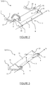
figure 2 est une représentation schématique en perspective d'un dispositif de rangement de lafigure 1 en position sortie, - la
figure 3 est une représentation schématique en perspective d'un dispositif de rangement de lafigure 1 en position rentrée, - la
figure 4 est une représentation schématique de côté d'un dispositif de rangement de lafigure 1 en position rentrée, - la
figure 5 est une représentation schématique de côté d'un dispositif de rangement de lafigure 1 en position sortie, et - la
figure 6 est une représentation schématique de côté du dispositif de rangement de lafigure 5 avec un bagage. - Il faut noter que les figures exposent l'invention de manière détaillée pour mettre en œuvre l'invention, lesdites figures pouvant bien entendu servir à mieux définir l'invention le cas échéant.
- En référence à la
figure 1 , il est représenté de manière partielle une voiture ferroviaire d'un véhicule ferroviaire. La voiture ferroviaire s'étend longitudinalement selon un axe X et comporte des parois sensiblement verticales P dans lesquelles sont montées des fenêtres (non représentées). - Comme illustré à la
figure 1 , la voiture ferroviaire comporte un plafond reliant les parois verticales de la voiture. Dans cette forme de réalisation, le plafond n'est pas horizontal mais incurvé de manière à ce que la hauteur sous plafond soit plus importante au centre de la voiture ferroviaire qu'à proximité des parois verticales P. La voiture ferroviaire comporte également un plancher sur lequel sont fixés plusieurs sièges. - La voiture ferroviaire comporte trois dispositifs de rangement 1 selon l'invention qui sont fixés à une paroi verticale P en partie supérieure, c'est à dire, au-dessus des fenêtres et sous le plafond. De manière préférée, chaque dispositif de rangement 1 est situé à une distance h du plafond qui est inférieure à 45 cm, de préférence, moins de 25 cm.
- Chaque dispositif de rangement 1 s'étend longitudinalement selon l'axe X, les dispositifs de rangement 1 étant adjacents les uns des autres et alignés selon un axe X de manière à permettre aux voyageurs de disposer de leurs effets personnels à proximité de leurs sièges.
- Comme illustré aux
figures 1 à 3 , chaque dispositif de rangement 1 comprend une partie principale 2, fixée à la paroi verticale P, et une partie auxiliaire 3, adaptée pour supporter un effet personnel. L'invention est remarquable en ce que la partie auxiliaire 3 est reliée à ladite partie principale 2 par des moyens de déplacement de manière à permettre à la partie auxiliaire 3 de se déplacer entre une position rentrée M1 dans laquelle la partie auxiliaire 3 s'étend à proximité de la paroi verticale P afin de permettre le rangement d'un effet personnel de taille réduite et une position sortie M2 dans laquelle la partie auxiliaire 3 s'étend à distance de la paroi verticale P afin de permettre le rangement d'un effet personnel. Dans cet exemple, la partie auxiliaire 3 s'étend à 25 cm de la paroi P en position rentrée M1 et 45 cm en position sortie M2. - En référence à la
figure 2 représentant un dispositif de rangement 1 en position sortie M2, la partie principale 2 comporte deux bras latéraux 20 qui sont parallèles. Chaque bras latéral 20 comporte une extrémité proximale solidaire de la paroi verticale P et une extrémité distale qui est relié à la partie auxiliaire 3 comme cela sera détaillé par la suite. Les bras latéraux 20 s'étendent orthogonalement à l'axe X selon lequel s'étend le dispositif de rangement 1. De manière préférée, l'écart longitudinal (défini selon l'axe X) entre les bras latéraux 20 est identique à l'écart entre les lieux de fixation d'un dispositif de rangement selon l'art antérieur du type «clayette», en particulier, de l'ordre de 55 cm. Ainsi, un dispositif de rangement 1 selon l'invention peut être mis en place en lieu et place d'un dispositif de rangement selon l'art antérieur. - Toujours en référence à la
figure 2 , chaque bras latéral 20 comporte des moyens de réception 21 de la partie auxiliaire 3 en position rentrée M1 afin de permettre de la stabiliser. De préférence, les moyens de réception 21 sont situés au niveau de la partie supérieure de chaque bras latéral 20. Dans cette forme de réalisation, les moyens de réception 21 se présentent sous la forme d'une encoche mais il va de soi qu'ils pourraient également se présenter sous la forme d'une empreinte. - En référence aux
figures 2 et 3 , la partie auxiliaire 3 comporte deux organes de liaison 30 reliés par un organe de support 31. Dans cette forme de réalisation, l'organe de support 31 est plan et possède une forme rectangulaire mais il va de soi qu'il pourrait posséder une forme différente. L'organe de support 31 s'étend parallèlement à l'axe X et les organes de liaison 30 s'étendent orthogonalement audit axe X. - Comme indiqué précédemment, la partie auxiliaire 3 est reliée à ladite partie principale 2 par des moyens de déplacement. De manière préférée, la partie auxiliaire 3 est articulée à la partie principale 2 par une liaison pivot 4 selon un axe parallèle à l'axe selon lequel s'étend le dispositif de rangement 1. Dans cet exemple la partie auxiliaire 3 est configurée pour former avec la partie principale 2 un angle θ compris entre 160 et 205° en position sortie M2. A cet effet, la partie principale 2 et la partie auxiliaire 3 comportent des moyens de butée pour définir de manière précise l'angle θ afin que la partie auxiliaire 3 s'étend à distance de la paroi verticale P en position sortie. De manière préférée, la partie auxiliaire 3 est sensiblement alignée avec la partie principale 2 de manière à augmenter la longueur en saillie depuis la paroi verticale 2.
- Dans cet exemple, en référence à la
figure 2 , l'organe de support 31 est articulé aux organes de liaison 30 par une liaison pivot 5 selon un axe X30 afin de permettre une inclinaison différente de l'organe de support 31 en position rentrée M1 et en position sortie M2. Les organes de liaison 30 comportent des moyens de butée configurés pour limiter l'inclinaison de l'organe de support 31. Dans cette forme de réalisation, les moyens de butée se présentent sous la forme d'une empreinte 32 formée dans la face intérieure de l'organe de liaison 30 comme illustré à lafigure 2 . De préférence, les moyens de butée autorisent un débattement angulaire β maximal de 45°. - En position sortie M2, l'organe de support 31 est incliné vers la paroi P, c'est-à-dire, son extrémité la plus proche de la paroi P est plus basse que son extrémité la plus éloignée de la paroi P comme illustré à la
figure 6 . De préférence, l'organe de support 31 est de préférence incliné par rapport au plan horizontal d'un angle d'inclinaison compris entre 5° et 15° de manière à incliner le bagage lorsqu'il est rangé comme cela sera présenté par la suite. - De manière avantageuse, la hauteur de la partie auxiliaire 3, en particulier l'organe de support 31, est plus basse en position sortie M2 qu'en position rentrée M1. Une telle caractéristique est avantageuse car elle permet d'augmenter l'espace vertical pour le rangement d'un bagage. Une telle caractéristique est d'autant plus avantageuse que la hauteur sous plafond est plus importante au centre de la voiture ferroviaire qu'à proximité des parois verticales P comme indiqué précédemment.
- Le dispositif de rangement 1 est ouvert en position sortie M2 et permet un support discret d'un bagage, c'est-à-dire, en une pluralité de points de supports élémentaires. La surface de support n'est pas continue, ce qui limite la masse du dispositif de rangement 1 et son encombrement, ce qui est avantageux.
- De manière préférée, en référence aux
figures 2 et 3 , la partie auxiliaire 3 comporte un organe de support 31 comportant une première face A et une deuxième face B opposée à la première face A, la partie auxiliaire 3 est adaptée pour supporter un bagage sur sa première face A en position rentrée M1 et sur sa deuxième face B en position sortie M2. - En référence à la
figure 3 , la partie auxiliaire 3 est configurée pour s'étendre sur la partie principale 2 en position rentrée M1. De manière préférée, l'organe de support 31 est adapté pour s'étendre de manière adjacente à la paroi du véhicule P en position rentrée M1. Un tel positionnement permet d'éviter qu'un effet personnel de petites dimensions ne glisse entre l'organe de support 31 et la paroi verticale P. De préférence encore, l'organe de support 31 s'étend sensiblement dans le plan horizontal de manière à former un support stable pour un effet personnel de petites dimensions. - Un exemple de mise en œuvre de l'invention va être dorénavant présenté en référence aux
figures 4 à 6 lors de l'utilisation d'un dispositif de rangement 1 par un voyageur. - Dans cet exemple, en référence à la
figure 4 , le dispositif de rangement 1 est situé au-dessus d'une fenêtre et au-dessus d'un siège pour voyageur. Le dispositif de rangement 1 est en position rentrée M1 afin de limiter l'encombrement dans la voiture ferroviaire et éviter qu'un voyageur ne le heurte lorsqu'il accède à son siège. L'organe de support 31 est en appui sur les bras latéraux 20 de la partie principale 2. - En position rentrée, le voyageur ne peut ranger que des effets personnels de faible dimension, ce qui correspond à un dispositif de rangement selon l'art antérieur du type « clayette ».
- Afin de pouvoir ranger un bagage du type cabine à proximité de son siège, le voyageur déplace la partie auxiliaire 3 en position sortie M2 de manière à ce qu'elle s'étende à distance de la paroi du véhicule P comme illustré à la
figure 5 . Puis, en référence à lafigure 6 , le voyageur peut positionner un bagage BB sur la partie auxiliaire 3 afin de le ranger. Lors du déplacement de la partie auxiliaire 3, l'organe de support 31 pivote de manière à s'incliner selon un angle prédétermine. De manière avantageuse, le bagage BB est supporté de manière inclinée afin de loger sous le plafond incliné. Le bagage s'étend, en partie, à travers le dispositif de rangement 1, entre le dispositif auxiliaire 30 et la paroi verticale P, afin d'optimiser l'espace disponible. Le débattement longitudinal selon l'axe X du bagage BB est avantageusement limité par les bras latéraux 20 de la partie principale 2. Aussi, grâce à l'invention, un bagage BB de grandes dimensions peut être rangé de manière stable et sécurisée à proximité du siège d'un voyageur lorsque la hauteur sous plafond est réduite.
Claims (8)
- Dispositif de rangement (1) destiné à être monté à proximité du plafond d'un véhicule de transport, le dispositif de rangement (1) comprenant au moins une partie principale (2), adaptée pour être fixée à une paroi (P) d'un véhicule de transport, et au moins une partie auxiliaire (3), adaptée pour supporter un effet personnel, la partie auxiliaire (3) est reliée à ladite partie principale (2) par des moyens de déplacement de manière à permettre à la partie auxiliaire (3) de se déplacer entre :i. une position rentrée (M1) dans laquelle la partie auxiliaire (3) s'étend à proximité de la paroi du véhicule (P) afin de permettre le rangement d'un effet personnel de taille réduite, notamment un vêtement, etii. une position sortie (M2) dans laquelle la partie auxiliaire (3) s'étend à distance de la paroi du véhicule (P) afin de permettre le rangement d'un effet personnel de taille importante, notamment un bagage de type cabinedispositif de rangement (1) caractérisé par le fait que la partie auxiliaire (3) comporte au moins un organe de liaison (30) et un organe de support (31) monté articulé par rapport audit organe de liaison (30) de manière à modifier l'inclinaison de l'organe de support (31) lorsque la partie auxiliaire (3) est en position rentrée (M1) ou en position sortie (M2), la partie auxiliaire (3) comportant un organe de support (31) comportant une première face (A) et une deuxième face (B) opposée à la première face (A), l'organe de support (31) étant adapté pour supporter un effet personnel sur sa première face (A) en position rentrée (M1) et sur sa deuxième face (B) en position sortie (M2).
- Dispositif selon la revendication 1, dans lequel la hauteur de la partie auxiliaire (3) est plus faible en position sortie (M2) qu'en position rentrée (M1).
- Dispositif selon l'une des revendications 1 à 2, dans lequel la partie auxiliaire (3) est articulée à la partie principale (2).
- Dispositif selon l'une des revendications 1 à 3, dans lequel, la partie auxiliaire (3) est configurée pour s'étendre sur la partie principale (2) en position rentrée (M1).
- Dispositif selon l'une des revendications 1 à 4, dans lequel la partie auxiliaire (3) est configurée pour former avec la partie principale (2) un angle (θ) compris entre 160° et 205° en position sortie (M2).
- Dispositif selon l'une des revendications 1 à 5, dans lequel la partie auxiliaire (3) comporte un organe de support (31) qui est adapté pour s'étendre de manière adjacente à la paroi du véhicule (P) en position rentrée (M1).
- Véhicule de transport comportant une paroi (P) et au moins un dispositif de rangement (1) selon l'une des revendications 1 à 6, la partie principale (2) étant solidarisée à la paroi (P).
- Méthode d'utilisation d'un dispositif de rangement (1) selon l'une des revendications 1 à 6 comportant une partie principale (2) fixée à une paroi (P) d'un véhicule de transport, le dispositif de rangement (1) étant en position rentrée (M1), la méthode comprenant :- une étape de déplacement de la partie auxiliaire (3) en position sortie (M2) de manière à ce qu'elle s'étende à distance de la paroi du véhicule (P) et- une étape de positionnement d'un effet personnel sur la partie auxiliaire (3) afin de le ranger.
Applications Claiming Priority (1)
| Application Number | Priority Date | Filing Date | Title |
|---|---|---|---|
| FR1756051A FR3068326B1 (fr) | 2017-06-29 | 2017-06-29 | Dispositif de rangement a proximite du plafond d'un vehicule de transport |
Publications (2)
| Publication Number | Publication Date |
|---|---|
| EP3421319A1 EP3421319A1 (fr) | 2019-01-02 |
| EP3421319B1 true EP3421319B1 (fr) | 2021-05-12 |
Family
ID=59811566
Family Applications (1)
| Application Number | Title | Priority Date | Filing Date |
|---|---|---|---|
| EP18177200.5A Active EP3421319B1 (fr) | 2017-06-29 | 2018-06-12 | Dispositif de rangement a proximite du plafond d'un vehicule de transport |
Country Status (3)
| Country | Link |
|---|---|
| EP (1) | EP3421319B1 (fr) |
| ES (1) | ES2881248T3 (fr) |
| FR (1) | FR3068326B1 (fr) |
Families Citing this family (2)
| Publication number | Priority date | Publication date | Assignee | Title |
|---|---|---|---|---|
| FR3123857B1 (fr) * | 2021-06-14 | 2025-05-02 | Speedinnov | Porte-bagages pour un véhicule terrestre et véhicule associé |
| CN116691756B (zh) * | 2023-07-21 | 2024-07-02 | 江阴奇南机械有限公司 | 一种防掉落行李架及轨道车 |
Family Cites Families (6)
| Publication number | Priority date | Publication date | Assignee | Title |
|---|---|---|---|---|
| DE508576C (de) * | 1930-03-22 | 1930-09-30 | Friedrich Lampe | Gepaecknetzhalter |
| US2093359A (en) * | 1937-03-12 | 1937-09-14 | Illmer Louis | Overhead luggage rack |
| US2973869A (en) * | 1958-05-08 | 1961-03-07 | Malcolm L Raymond | Baggage rack |
| FR2908383B1 (fr) * | 2006-11-13 | 2009-12-18 | Airbus | Dispositif pour le rangement de bagages destine a un vehicule de transport de passagers,tel par exemple un aeronef |
| FR2965525A1 (fr) * | 2010-10-04 | 2012-04-06 | Peugeot Citroen Automobiles Sa | Dispositif de support et de retenue a surface de support variable pour un rangement |
| DE102014203893A1 (de) * | 2014-03-04 | 2015-09-10 | Siemens Aktiengesellschaft | Fahrzeug mit Gepäckablage |
-
2017
- 2017-06-29 FR FR1756051A patent/FR3068326B1/fr active Active
-
2018
- 2018-06-12 ES ES18177200T patent/ES2881248T3/es active Active
- 2018-06-12 EP EP18177200.5A patent/EP3421319B1/fr active Active
Non-Patent Citations (1)
| Title |
|---|
| None * |
Also Published As
| Publication number | Publication date |
|---|---|
| FR3068326A1 (fr) | 2019-01-04 |
| FR3068326B1 (fr) | 2020-06-19 |
| EP3421319A1 (fr) | 2019-01-02 |
| ES2881248T3 (es) | 2021-11-29 |
Similar Documents
| Publication | Publication Date | Title |
|---|---|---|
| EP3601044B1 (fr) | Arrangement de sièges individuels pour passagers d'un avion muni de supports d'écran formant paroi de séparation | |
| EP2502799B1 (fr) | Installation de transport par câble aérien munie d'un véhicule de maintenance | |
| EP2219945B1 (fr) | Aménagement optimisé d'une cabine d'aéronef | |
| FR3048235A1 (fr) | Outillage pour l'integration d'un module dans un aeronef et procede d'integration associe | |
| FR2902052A1 (fr) | Siege depliable pour vehicule de transport, et vehicule de transport correspondant | |
| EP3300488B1 (fr) | Véhicule de transport destiné à être tracté par un câble aérien et installation comprenant un tel véhicule | |
| EP3421319A1 (fr) | Dispositif de rangement a proximite du plafond d'un vehicule de transport | |
| CA2697117C (fr) | Conteneur a bagage | |
| FR3128938A1 (fr) | Ensemble structurel pour un aéronef | |
| EP2378620B1 (fr) | Chemin de câbles comprenant au moins une goulotte et au moins un support, et méthode de montage d'une telle goulotte sur un tel support | |
| FR3064596A1 (fr) | Train d'atterrissage avant de hauteur reduite et aeronef, en particulier aile volante, equipe d'un tel train avant | |
| WO2009007547A2 (fr) | Soute d'aéronef destinée à recevoir des bagages | |
| EP3199723A1 (fr) | Garde-corps autoporté | |
| FR3037935A1 (fr) | Chariot a plateau inclinable, pour un appareil de convoyage au sol | |
| EP3257703B1 (fr) | Vehicule de transport de voyageurs comprenant un dispositif d'assise suspendu | |
| FR3100232A1 (fr) | Ensemble comportant une tour support et au moins deux systemes de support pour des panneaux d’un troncon de fuselage d’un aeronef | |
| EP3792167B1 (fr) | Dispositif de rangement pour vélos, et voiture ferroviaire, telle qu'un wagon, comportant un dispositif de rangement pour vélos de ce type | |
| FR3040408A1 (fr) | Structure modulaire de travail pour cage d'escalier | |
| EP4032779B1 (fr) | Dispositif de comble-lacune à brosse pour la maintenance de matériel roulant ferroviaire | |
| EP3650300B1 (fr) | Installation telepherique comprenant une structure de virage | |
| EP3275728B1 (fr) | Siège pour passager de véhicule de transport public, à élément de maintien escamotable | |
| FR3162402A1 (fr) | Dispositif pliable/déployable pour sièges de passagers d’un véhicule de transport | |
| FR2545706A1 (fr) | Systeme de sieges escamotables | |
| FR2576857A3 (fr) | Wagon a plate-forme superieure ajustable en hauteur, pour le transport d'autos et vehicules similaires | |
| FR3149591A1 (fr) | Arrangement d'unites de sieges et cabine d'avion comportant un tel arrangement d'unites de sieges |
Legal Events
| Date | Code | Title | Description |
|---|---|---|---|
| PUAI | Public reference made under article 153(3) epc to a published international application that has entered the european phase |
Free format text: ORIGINAL CODE: 0009012 |
|
| STAA | Information on the status of an ep patent application or granted ep patent |
Free format text: STATUS: THE APPLICATION HAS BEEN PUBLISHED |
|
| AK | Designated contracting states |
Kind code of ref document: A1 Designated state(s): AL AT BE BG CH CY CZ DE DK EE ES FI FR GB GR HR HU IE IS IT LI LT LU LV MC MK MT NL NO PL PT RO RS SE SI SK SM TR |
|
| AX | Request for extension of the european patent |
Extension state: BA ME |
|
| STAA | Information on the status of an ep patent application or granted ep patent |
Free format text: STATUS: REQUEST FOR EXAMINATION WAS MADE |
|
| 17P | Request for examination filed |
Effective date: 20190606 |
|
| RBV | Designated contracting states (corrected) |
Designated state(s): AL AT BE BG CH CY CZ DE DK EE ES FI FR GB GR HR HU IE IS IT LI LT LU LV MC MK MT NL NO PL PT RO RS SE SI SK SM TR |
|
| GRAP | Despatch of communication of intention to grant a patent |
Free format text: ORIGINAL CODE: EPIDOSNIGR1 |
|
| STAA | Information on the status of an ep patent application or granted ep patent |
Free format text: STATUS: GRANT OF PATENT IS INTENDED |
|
| INTG | Intention to grant announced |
Effective date: 20201110 |
|
| GRAJ | Information related to disapproval of communication of intention to grant by the applicant or resumption of examination proceedings by the epo deleted |
Free format text: ORIGINAL CODE: EPIDOSDIGR1 |
|
| STAA | Information on the status of an ep patent application or granted ep patent |
Free format text: STATUS: REQUEST FOR EXAMINATION WAS MADE |
|
| GRAP | Despatch of communication of intention to grant a patent |
Free format text: ORIGINAL CODE: EPIDOSNIGR1 |
|
| STAA | Information on the status of an ep patent application or granted ep patent |
Free format text: STATUS: GRANT OF PATENT IS INTENDED |
|
| INTC | Intention to grant announced (deleted) | ||
| GRAS | Grant fee paid |
Free format text: ORIGINAL CODE: EPIDOSNIGR3 |
|
| GRAA | (expected) grant |
Free format text: ORIGINAL CODE: 0009210 |
|
| STAA | Information on the status of an ep patent application or granted ep patent |
Free format text: STATUS: THE PATENT HAS BEEN GRANTED |
|
| INTG | Intention to grant announced |
Effective date: 20210323 |
|
| AK | Designated contracting states |
Kind code of ref document: B1 Designated state(s): AL AT BE BG CH CY CZ DE DK EE ES FI FR GB GR HR HU IE IS IT LI LT LU LV MC MK MT NL NO PL PT RO RS SE SI SK SM TR |
|
| REG | Reference to a national code |
Ref country code: GB Ref legal event code: FG4D Free format text: NOT ENGLISH |
|
| REG | Reference to a national code |
Ref country code: CH Ref legal event code: EP |
|
| REG | Reference to a national code |
Ref country code: DE Ref legal event code: R096 Ref document number: 602018016941 Country of ref document: DE |
|
| REG | Reference to a national code |
Ref country code: IE Ref legal event code: FG4D Free format text: LANGUAGE OF EP DOCUMENT: FRENCH |
|
| REG | Reference to a national code |
Ref country code: AT Ref legal event code: REF Ref document number: 1392015 Country of ref document: AT Kind code of ref document: T Effective date: 20210615 |
|
| REG | Reference to a national code |
Ref country code: LT Ref legal event code: MG9D |
|
| REG | Reference to a national code |
Ref country code: AT Ref legal event code: MK05 Ref document number: 1392015 Country of ref document: AT Kind code of ref document: T Effective date: 20210512 |
|
| REG | Reference to a national code |
Ref country code: NL Ref legal event code: MP Effective date: 20210512 |
|
| PG25 | Lapsed in a contracting state [announced via postgrant information from national office to epo] |
Ref country code: AT Free format text: LAPSE BECAUSE OF FAILURE TO SUBMIT A TRANSLATION OF THE DESCRIPTION OR TO PAY THE FEE WITHIN THE PRESCRIBED TIME-LIMIT Effective date: 20210512 Ref country code: BG Free format text: LAPSE BECAUSE OF FAILURE TO SUBMIT A TRANSLATION OF THE DESCRIPTION OR TO PAY THE FEE WITHIN THE PRESCRIBED TIME-LIMIT Effective date: 20210812 Ref country code: FI Free format text: LAPSE BECAUSE OF FAILURE TO SUBMIT A TRANSLATION OF THE DESCRIPTION OR TO PAY THE FEE WITHIN THE PRESCRIBED TIME-LIMIT Effective date: 20210512 Ref country code: HR Free format text: LAPSE BECAUSE OF FAILURE TO SUBMIT A TRANSLATION OF THE DESCRIPTION OR TO PAY THE FEE WITHIN THE PRESCRIBED TIME-LIMIT Effective date: 20210512 Ref country code: LT Free format text: LAPSE BECAUSE OF FAILURE TO SUBMIT A TRANSLATION OF THE DESCRIPTION OR TO PAY THE FEE WITHIN THE PRESCRIBED TIME-LIMIT Effective date: 20210512 |
|
| REG | Reference to a national code |
Ref country code: ES Ref legal event code: FG2A Ref document number: 2881248 Country of ref document: ES Kind code of ref document: T3 Effective date: 20211129 |
|
| PG25 | Lapsed in a contracting state [announced via postgrant information from national office to epo] |
Ref country code: GR Free format text: LAPSE BECAUSE OF FAILURE TO SUBMIT A TRANSLATION OF THE DESCRIPTION OR TO PAY THE FEE WITHIN THE PRESCRIBED TIME-LIMIT Effective date: 20210813 Ref country code: IS Free format text: LAPSE BECAUSE OF FAILURE TO SUBMIT A TRANSLATION OF THE DESCRIPTION OR TO PAY THE FEE WITHIN THE PRESCRIBED TIME-LIMIT Effective date: 20210912 Ref country code: PL Free format text: LAPSE BECAUSE OF FAILURE TO SUBMIT A TRANSLATION OF THE DESCRIPTION OR TO PAY THE FEE WITHIN THE PRESCRIBED TIME-LIMIT Effective date: 20210512 Ref country code: LV Free format text: LAPSE BECAUSE OF FAILURE TO SUBMIT A TRANSLATION OF THE DESCRIPTION OR TO PAY THE FEE WITHIN THE PRESCRIBED TIME-LIMIT Effective date: 20210512 Ref country code: PT Free format text: LAPSE BECAUSE OF FAILURE TO SUBMIT A TRANSLATION OF THE DESCRIPTION OR TO PAY THE FEE WITHIN THE PRESCRIBED TIME-LIMIT Effective date: 20210913 Ref country code: NO Free format text: LAPSE BECAUSE OF FAILURE TO SUBMIT A TRANSLATION OF THE DESCRIPTION OR TO PAY THE FEE WITHIN THE PRESCRIBED TIME-LIMIT Effective date: 20210812 Ref country code: SE Free format text: LAPSE BECAUSE OF FAILURE TO SUBMIT A TRANSLATION OF THE DESCRIPTION OR TO PAY THE FEE WITHIN THE PRESCRIBED TIME-LIMIT Effective date: 20210512 Ref country code: RS Free format text: LAPSE BECAUSE OF FAILURE TO SUBMIT A TRANSLATION OF THE DESCRIPTION OR TO PAY THE FEE WITHIN THE PRESCRIBED TIME-LIMIT Effective date: 20210512 |
|
| PG25 | Lapsed in a contracting state [announced via postgrant information from national office to epo] |
Ref country code: NL Free format text: LAPSE BECAUSE OF FAILURE TO SUBMIT A TRANSLATION OF THE DESCRIPTION OR TO PAY THE FEE WITHIN THE PRESCRIBED TIME-LIMIT Effective date: 20210512 |
|
| PG25 | Lapsed in a contracting state [announced via postgrant information from national office to epo] |
Ref country code: SM Free format text: LAPSE BECAUSE OF FAILURE TO SUBMIT A TRANSLATION OF THE DESCRIPTION OR TO PAY THE FEE WITHIN THE PRESCRIBED TIME-LIMIT Effective date: 20210512 Ref country code: SK Free format text: LAPSE BECAUSE OF FAILURE TO SUBMIT A TRANSLATION OF THE DESCRIPTION OR TO PAY THE FEE WITHIN THE PRESCRIBED TIME-LIMIT Effective date: 20210512 Ref country code: EE Free format text: LAPSE BECAUSE OF FAILURE TO SUBMIT A TRANSLATION OF THE DESCRIPTION OR TO PAY THE FEE WITHIN THE PRESCRIBED TIME-LIMIT Effective date: 20210512 Ref country code: RO Free format text: LAPSE BECAUSE OF FAILURE TO SUBMIT A TRANSLATION OF THE DESCRIPTION OR TO PAY THE FEE WITHIN THE PRESCRIBED TIME-LIMIT Effective date: 20210512 Ref country code: CZ Free format text: LAPSE BECAUSE OF FAILURE TO SUBMIT A TRANSLATION OF THE DESCRIPTION OR TO PAY THE FEE WITHIN THE PRESCRIBED TIME-LIMIT Effective date: 20210512 Ref country code: DK Free format text: LAPSE BECAUSE OF FAILURE TO SUBMIT A TRANSLATION OF THE DESCRIPTION OR TO PAY THE FEE WITHIN THE PRESCRIBED TIME-LIMIT Effective date: 20210512 |
|
| REG | Reference to a national code |
Ref country code: DE Ref legal event code: R097 Ref document number: 602018016941 Country of ref document: DE |
|
| PLBE | No opposition filed within time limit |
Free format text: ORIGINAL CODE: 0009261 |
|
| STAA | Information on the status of an ep patent application or granted ep patent |
Free format text: STATUS: NO OPPOSITION FILED WITHIN TIME LIMIT |
|
| 26N | No opposition filed |
Effective date: 20220215 |
|
| PG25 | Lapsed in a contracting state [announced via postgrant information from national office to epo] |
Ref country code: IE Free format text: LAPSE BECAUSE OF NON-PAYMENT OF DUE FEES Effective date: 20210612 |
|
| PG25 | Lapsed in a contracting state [announced via postgrant information from national office to epo] |
Ref country code: IS Free format text: LAPSE BECAUSE OF FAILURE TO SUBMIT A TRANSLATION OF THE DESCRIPTION OR TO PAY THE FEE WITHIN THE PRESCRIBED TIME-LIMIT Effective date: 20210912 Ref country code: AL Free format text: LAPSE BECAUSE OF FAILURE TO SUBMIT A TRANSLATION OF THE DESCRIPTION OR TO PAY THE FEE WITHIN THE PRESCRIBED TIME-LIMIT Effective date: 20210512 |
|
| REG | Reference to a national code |
Ref country code: DE Ref legal event code: R081 Ref document number: 602018016941 Country of ref document: DE Owner name: SNCF VOYAGEURS, FR Free format text: FORMER OWNER: SNCF MOBILITES, SAINT-DENIS, FR |
|
| REG | Reference to a national code |
Ref country code: GB Ref legal event code: 732E Free format text: REGISTERED BETWEEN 20230602 AND 20230607 |
|
| PG25 | Lapsed in a contracting state [announced via postgrant information from national office to epo] |
Ref country code: CY Free format text: LAPSE BECAUSE OF FAILURE TO SUBMIT A TRANSLATION OF THE DESCRIPTION OR TO PAY THE FEE WITHIN THE PRESCRIBED TIME-LIMIT Effective date: 20210512 |
|
| P01 | Opt-out of the competence of the unified patent court (upc) registered |
Effective date: 20230530 |
|
| REG | Reference to a national code |
Ref country code: BE Ref legal event code: PD Owner name: SNCF VOYAGEURS; FR Free format text: DETAILS ASSIGNMENT: CHANGE OF OWNER(S), ASSIGNMENT; FORMER OWNER NAME: SNCF MOBILITES Effective date: 20230508 |
|
| PG25 | Lapsed in a contracting state [announced via postgrant information from national office to epo] |
Ref country code: HU Free format text: LAPSE BECAUSE OF FAILURE TO SUBMIT A TRANSLATION OF THE DESCRIPTION OR TO PAY THE FEE WITHIN THE PRESCRIBED TIME-LIMIT; INVALID AB INITIO Effective date: 20180612 |
|
| PG25 | Lapsed in a contracting state [announced via postgrant information from national office to epo] |
Ref country code: MK Free format text: LAPSE BECAUSE OF FAILURE TO SUBMIT A TRANSLATION OF THE DESCRIPTION OR TO PAY THE FEE WITHIN THE PRESCRIBED TIME-LIMIT Effective date: 20210512 |
|
| PG25 | Lapsed in a contracting state [announced via postgrant information from national office to epo] |
Ref country code: MT Free format text: LAPSE BECAUSE OF FAILURE TO SUBMIT A TRANSLATION OF THE DESCRIPTION OR TO PAY THE FEE WITHIN THE PRESCRIBED TIME-LIMIT Effective date: 20210512 |
|
| REG | Reference to a national code |
Ref country code: ES Ref legal event code: PC2A Owner name: SNCF VOYAGEURS Effective date: 20241011 |
|
| PGFP | Annual fee paid to national office [announced via postgrant information from national office to epo] |
Ref country code: MC Payment date: 20250527 Year of fee payment: 8 |
|
| PGFP | Annual fee paid to national office [announced via postgrant information from national office to epo] |
Ref country code: DE Payment date: 20250617 Year of fee payment: 8 |
|
| PGFP | Annual fee paid to national office [announced via postgrant information from national office to epo] |
Ref country code: GB Payment date: 20250625 Year of fee payment: 8 |
|
| PGFP | Annual fee paid to national office [announced via postgrant information from national office to epo] |
Ref country code: LU Payment date: 20250528 Year of fee payment: 8 Ref country code: BE Payment date: 20250625 Year of fee payment: 8 |
|
| PGFP | Annual fee paid to national office [announced via postgrant information from national office to epo] |
Ref country code: FR Payment date: 20250630 Year of fee payment: 8 |
|
| PGFP | Annual fee paid to national office [announced via postgrant information from national office to epo] |
Ref country code: ES Payment date: 20250710 Year of fee payment: 8 |
|
| PGFP | Annual fee paid to national office [announced via postgrant information from national office to epo] |
Ref country code: IT Payment date: 20250609 Year of fee payment: 8 |
|
| PGFP | Annual fee paid to national office [announced via postgrant information from national office to epo] |
Ref country code: CH Payment date: 20250701 Year of fee payment: 8 |
|
| PG25 | Lapsed in a contracting state [announced via postgrant information from national office to epo] |
Ref country code: TR Free format text: LAPSE BECAUSE OF FAILURE TO SUBMIT A TRANSLATION OF THE DESCRIPTION OR TO PAY THE FEE WITHIN THE PRESCRIBED TIME-LIMIT Effective date: 20210512 |