EP3421022B1 - Vorrichtung und verfahren zur herstellung dehnfolienseitenwände und nicht dehnbahre seitenwände für absorbierender artikel - Google Patents
Vorrichtung und verfahren zur herstellung dehnfolienseitenwände und nicht dehnbahre seitenwände für absorbierender artikel Download PDFInfo
- Publication number
- EP3421022B1 EP3421022B1 EP18180992.2A EP18180992A EP3421022B1 EP 3421022 B1 EP3421022 B1 EP 3421022B1 EP 18180992 A EP18180992 A EP 18180992A EP 3421022 B1 EP3421022 B1 EP 3421022B1
- Authority
- EP
- European Patent Office
- Prior art keywords
- elasticized
- sheet
- panels
- composite
- transverse
- Prior art date
- Legal status (The legal status is an assumption and is not a legal conclusion. Google has not performed a legal analysis and makes no representation as to the accuracy of the status listed.)
- Active
Links
Images


Classifications
-
- B—PERFORMING OPERATIONS; TRANSPORTING
- B32—LAYERED PRODUCTS
- B32B—LAYERED PRODUCTS, i.e. PRODUCTS BUILT-UP OF STRATA OF FLAT OR NON-FLAT, e.g. CELLULAR OR HONEYCOMB, FORM
- B32B37/00—Methods or apparatus for laminating, e.g. by curing or by ultrasonic bonding
- B32B37/14—Methods or apparatus for laminating, e.g. by curing or by ultrasonic bonding characterised by the properties of the layers
- B32B37/16—Methods or apparatus for laminating, e.g. by curing or by ultrasonic bonding characterised by the properties of the layers with all layers existing as coherent layers before laminating
- B32B37/22—Methods or apparatus for laminating, e.g. by curing or by ultrasonic bonding characterised by the properties of the layers with all layers existing as coherent layers before laminating involving the assembly of both discrete and continuous layers
-
- A—HUMAN NECESSITIES
- A61—MEDICAL OR VETERINARY SCIENCE; HYGIENE
- A61F—FILTERS IMPLANTABLE INTO BLOOD VESSELS; PROSTHESES; DEVICES PROVIDING PATENCY TO, OR PREVENTING COLLAPSING OF, TUBULAR STRUCTURES OF THE BODY, e.g. STENTS; ORTHOPAEDIC, NURSING OR CONTRACEPTIVE DEVICES; FOMENTATION; TREATMENT OR PROTECTION OF EYES OR EARS; BANDAGES, DRESSINGS OR ABSORBENT PADS; FIRST-AID KITS
- A61F13/00—Bandages or dressings; Absorbent pads
- A61F13/15—Absorbent pads, e.g. sanitary towels, swabs or tampons for external or internal application to the body; Supporting or fastening means therefor; Tampon applicators
- A61F13/56—Supporting or fastening means
- A61F13/5622—Supporting or fastening means specially adapted for diapers or the like
- A61F13/5633—Supporting or fastening means specially adapted for diapers or the like open type diaper
-
- A—HUMAN NECESSITIES
- A61—MEDICAL OR VETERINARY SCIENCE; HYGIENE
- A61F—FILTERS IMPLANTABLE INTO BLOOD VESSELS; PROSTHESES; DEVICES PROVIDING PATENCY TO, OR PREVENTING COLLAPSING OF, TUBULAR STRUCTURES OF THE BODY, e.g. STENTS; ORTHOPAEDIC, NURSING OR CONTRACEPTIVE DEVICES; FOMENTATION; TREATMENT OR PROTECTION OF EYES OR EARS; BANDAGES, DRESSINGS OR ABSORBENT PADS; FIRST-AID KITS
- A61F13/00—Bandages or dressings; Absorbent pads
- A61F13/15—Absorbent pads, e.g. sanitary towels, swabs or tampons for external or internal application to the body; Supporting or fastening means therefor; Tampon applicators
- A61F13/15577—Apparatus or processes for manufacturing
- A61F13/15585—Apparatus or processes for manufacturing of babies' napkins, e.g. diapers
-
- A—HUMAN NECESSITIES
- A61—MEDICAL OR VETERINARY SCIENCE; HYGIENE
- A61F—FILTERS IMPLANTABLE INTO BLOOD VESSELS; PROSTHESES; DEVICES PROVIDING PATENCY TO, OR PREVENTING COLLAPSING OF, TUBULAR STRUCTURES OF THE BODY, e.g. STENTS; ORTHOPAEDIC, NURSING OR CONTRACEPTIVE DEVICES; FOMENTATION; TREATMENT OR PROTECTION OF EYES OR EARS; BANDAGES, DRESSINGS OR ABSORBENT PADS; FIRST-AID KITS
- A61F13/00—Bandages or dressings; Absorbent pads
- A61F13/15—Absorbent pads, e.g. sanitary towels, swabs or tampons for external or internal application to the body; Supporting or fastening means therefor; Tampon applicators
- A61F13/15577—Apparatus or processes for manufacturing
- A61F13/15756—Applying tabs, strips, tapes, loops; Knotting the ends of pads
-
- B—PERFORMING OPERATIONS; TRANSPORTING
- B32—LAYERED PRODUCTS
- B32B—LAYERED PRODUCTS, i.e. PRODUCTS BUILT-UP OF STRATA OF FLAT OR NON-FLAT, e.g. CELLULAR OR HONEYCOMB, FORM
- B32B3/00—Layered products comprising a layer with external or internal discontinuities or unevennesses, or a layer of non-planar shape; Layered products comprising a layer having particular features of form
- B32B3/10—Layered products comprising a layer with external or internal discontinuities or unevennesses, or a layer of non-planar shape; Layered products comprising a layer having particular features of form characterised by a discontinuous layer, i.e. formed of separate pieces of material
- B32B3/14—Layered products comprising a layer with external or internal discontinuities or unevennesses, or a layer of non-planar shape; Layered products comprising a layer having particular features of form characterised by a discontinuous layer, i.e. formed of separate pieces of material characterised by a face layer formed of separate pieces of material which are juxtaposed side-by-side
-
- B—PERFORMING OPERATIONS; TRANSPORTING
- B32—LAYERED PRODUCTS
- B32B—LAYERED PRODUCTS, i.e. PRODUCTS BUILT-UP OF STRATA OF FLAT OR NON-FLAT, e.g. CELLULAR OR HONEYCOMB, FORM
- B32B38/00—Ancillary operations in connection with laminating processes
- B32B38/0004—Cutting, tearing or severing, e.g. bursting; Cutter details
-
- B—PERFORMING OPERATIONS; TRANSPORTING
- B32—LAYERED PRODUCTS
- B32B—LAYERED PRODUCTS, i.e. PRODUCTS BUILT-UP OF STRATA OF FLAT OR NON-FLAT, e.g. CELLULAR OR HONEYCOMB, FORM
- B32B38/00—Ancillary operations in connection with laminating processes
- B32B38/0012—Mechanical treatment, e.g. roughening, deforming, stretching
-
- B—PERFORMING OPERATIONS; TRANSPORTING
- B32—LAYERED PRODUCTS
- B32B—LAYERED PRODUCTS, i.e. PRODUCTS BUILT-UP OF STRATA OF FLAT OR NON-FLAT, e.g. CELLULAR OR HONEYCOMB, FORM
- B32B38/00—Ancillary operations in connection with laminating processes
- B32B38/04—Punching, slitting or perforating
-
- B—PERFORMING OPERATIONS; TRANSPORTING
- B32—LAYERED PRODUCTS
- B32B—LAYERED PRODUCTS, i.e. PRODUCTS BUILT-UP OF STRATA OF FLAT OR NON-FLAT, e.g. CELLULAR OR HONEYCOMB, FORM
- B32B7/00—Layered products characterised by the relation between layers; Layered products characterised by the relative orientation of features between layers, or by the relative values of a measurable parameter between layers, i.e. products comprising layers having different physical, chemical or physicochemical properties; Layered products characterised by the interconnection of layers
- B32B7/02—Physical, chemical or physicochemical properties
- B32B7/022—Mechanical properties
-
- B—PERFORMING OPERATIONS; TRANSPORTING
- B32—LAYERED PRODUCTS
- B32B—LAYERED PRODUCTS, i.e. PRODUCTS BUILT-UP OF STRATA OF FLAT OR NON-FLAT, e.g. CELLULAR OR HONEYCOMB, FORM
- B32B38/00—Ancillary operations in connection with laminating processes
- B32B38/04—Punching, slitting or perforating
- B32B2038/047—Perforating
-
- B—PERFORMING OPERATIONS; TRANSPORTING
- B32—LAYERED PRODUCTS
- B32B—LAYERED PRODUCTS, i.e. PRODUCTS BUILT-UP OF STRATA OF FLAT OR NON-FLAT, e.g. CELLULAR OR HONEYCOMB, FORM
- B32B2250/00—Layers arrangement
- B32B2250/02—2 layers
-
- B—PERFORMING OPERATIONS; TRANSPORTING
- B32—LAYERED PRODUCTS
- B32B—LAYERED PRODUCTS, i.e. PRODUCTS BUILT-UP OF STRATA OF FLAT OR NON-FLAT, e.g. CELLULAR OR HONEYCOMB, FORM
- B32B2307/00—Properties of the layers or laminate
- B32B2307/50—Properties of the layers or laminate having particular mechanical properties
- B32B2307/51—Elastic
-
- B—PERFORMING OPERATIONS; TRANSPORTING
- B32—LAYERED PRODUCTS
- B32B—LAYERED PRODUCTS, i.e. PRODUCTS BUILT-UP OF STRATA OF FLAT OR NON-FLAT, e.g. CELLULAR OR HONEYCOMB, FORM
- B32B2307/00—Properties of the layers or laminate
- B32B2307/70—Other properties
- B32B2307/726—Permeability to liquids, absorption
-
- B—PERFORMING OPERATIONS; TRANSPORTING
- B32—LAYERED PRODUCTS
- B32B—LAYERED PRODUCTS, i.e. PRODUCTS BUILT-UP OF STRATA OF FLAT OR NON-FLAT, e.g. CELLULAR OR HONEYCOMB, FORM
- B32B2555/00—Personal care
- B32B2555/02—Diapers or napkins
Definitions
- the present invention relates to an apparatus and a method for producing side panels for absorbent sanitary articles.
- the present invention has been developed in particular for producing elasticized panels intended to be applied to the waist region of disposable absorbent sanitary articles, for example, of the type for babies or for incontinent adults.
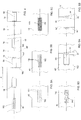
- FIG. 1 In the field of sanitary articles wearable as pants, typically diapers for babies or incontinence pads for adults, the general structure represented, by way of example, in Figure 1 has been increasingly affirmed, where an article of the type considered here is represented in the unfolded condition and with the surface that is in contact with the user's body facing the observer.
- the sanitary article 10 illustrated in Figure 1 comprises front and rear side panels, and is here referred to as a generic example of the structure of this type of article.
- the article 10 comprises a central body or "chassis” 12 intended to be arranged according to a general basin configuration around the user's groin area.
- the central body 12 includes an absorbent core, sandwiched between a topsheet, which can be partially or totally permeable to body liquids and an impermeable lower sheet, or backsheet.
- rear 16 and front 18 side panels are provided, respectively, connectable in the closed condition around the user's waistline by means of closing elements 20 placed, for example, at the distal margins of the rear side panels 16.
- the side panels 16, 18 can be shaped or rectangular, for example, in the product structure shown in Figure 1 , both the rear side panels 16 and the front side panels 18 are shaped, typically in the form of a rectangular trapezoid, but in a common alternative embodiment, the front side panels 18 may, for example, be rectangular.
- These elastic elements are typically incorporated into the side panels according to known techniques, in general when forming the side panels themselves.
- the side panels 16, 18, both of the elasticized and the non-elasticized type are made from continuous webs of composite or stratified materials, and are then applied to the chassis 12, generally to a continuous web of composite material from which the individual chassis are subsequently obtained, or more commonly, to a continuous web of material intended to be part of the chassis 12 in a subsequent formation step, such as, for example, a continuous web of material intended to form the topsheet.
- Elasticized side panels are obviously more expensive than those that do not have this characteristic, both due to the greater complexity of construction, and for the need to incorporate more valuable and expensive materials into the structure, typically elastic materials in the form of films or filaments, combined with non-elastic materials, typically consisting of nonwoven fabrics and/or polymeric films. Therefore for average or economically-priced sanitary articles, excluding therefore those of the "premium" category, a satisfactory compromise between quality and price can be represented by a combination of elasticized rear panels and non-elasticized front panels.
- the present invention aims to provide an apparatus and a method for producing side panels for applying to absorbent sanitary articles wearable as pants, which allows elasticized and non-elasticized side panels to be produced, by means of a single device incorporated in the production line.
- this object is achieved, by a method and by an apparatus having the characteristics forming the subject of the attached claims.
- the figures refer to a method and an apparatus for producing elasticized composite panels 16 and non-elasticized panels 18 for an absorbent sanitary article 10.
- the elasticized composite panels 16 and the non-elasticized panels 18 form the side panels of an absorbent sanitary article 10.
- the method comprises: feeding a sheet 46 having side edges along a feed direction; forming controlled activation zones 152 in the sheet 46 within the side edges, spaced apart from each other along the feed direction, wherein each of the controlled activation zones 152 comprises activation elements selected in an assembly consisting of cuts 154, 156, holes 158, mechanical deformation 160, and combinations thereof; attaching elastic elements 68 onto the sheet 46 at respective controlled activation zones 152 to form a composite web 46'; making transverse cuts 182, 182', 82, 82a, 82b, 82' at predetermined intervals on the composite web 46' each crossing at least part of one of the controlled activation zones 152 to form elasticized composite panels 16 comprising at least part of an elastic element 68, and non-elasticized panels 18.
- the activation elements make the sheet 46 extensible in a direction perpendicular to the feed direction at the controlled activation zones 152. They also have the advantage of creating a simpler fastening of the elastic element 68 to the sheet 46, and of effectively using the combined action of the elastic element 68 with the controlled activation zone 152 of the sheet 46 in the elasticized composite panels 16.
- transverse cuts 182, 182' form elasticized composite panels 16 and non-elasticized panels 18 from the composite strip 46' without producing scraps, thus with a lower use of materials.
- transverse cuts 82, 82a, 82b, 82' remove transverse portions 84, 84' from the composite web 46', which comprise at least one part of the controlled activation zones 152, to form the composite elasticized panels 16 and the non-elasticized panels 18. These portions 84, 84' can be rejected as scrap.
- the removed transverse portions 84, 84' can comprise at least one part of the respective elastic elements 68.
- transverse portions 84, 84' from the composite web 46', comprising at least one part of the controlled activation zones 152 and of the respective elastic elements 68 has the advantage of forming elasticized composite panels 16 and non-elasticized panels 18 having more regular transverse edges, made from cuts 82, 82a, 82b, 82' as shown, for example, in Figures 6B and 8 , even though due to the scraps it may involve a slightly greater use of material.
- the activation elements of the controlled activation zones 152 may comprise cuts 154, 156, which are advantageous as they do not entail removal of material from the sheet 46.
- the activation elements may comprise discontinuous cuts 154.
- the discontinuous cuts 154 can be aligned in rows parallel to each other.
- the discontinuous cuts 154 can be aligned in rows parallel and offset to each other.
- the activation elements may comprise continuous cuts 156.
- the continuous cuts 156 can be aligned in rows parallel to each other.
- the activation elements of the controlled activation zones 152 may comprise holes 158, which are advantageous in that they give the sheet 46 extensibility at the controlled activation zones 152, with a better resistance to stresses.
- the holes 158 can be circular.
- the holes 158 may have an elongated shape with a major dimension orientated in the feed direction, so as to give the sheet 46 a greater extensibility in a direction perpendicular to their major dimension.
- the holes 158 can be arranged in parallel rows with each other.
- the holes 158 can be arranged in parallel rows offset from each other.
- the activation elements of the controlled activation zones 152 may comprise a mechanical deformation 160 of the sheet 46, which is advantageous in that it gives the sheet 46 extensibility at the controlled activation zones 152, maintaining the continuity of the sheet 46 itself, without the need to create holes or cuts.
- the mechanical deformation 160 can be obtained by stretching the sheet 46 at least in a direction perpendicular to the feed direction, at the controlled activation zones 152 until a permanent elongation is achieved at these zones.
- the controlled activation zones 152 can be formed in the sheet 46 spaced from each another along the feed direction by a pitch P that can be fixed or variable, or alternated, or with sections with a first pitch alternated with sections with a second pitch different from the first, and combinations thereof.
- the elastic elements 68 - in a relaxed condition - may extend at least partly beyond the controlled activation zones 152 in a direction perpendicular to the feed direction of the sheet 46 and towards both the side edges.
- the elastic elements 68 can be attached to the sheet 46 at least at the zones where they extend beyond the controlled activation zones 152 in a direction perpendicular to the feed direction of the sheet 46 and towards the side edges.
- the controlled activation zones 152 may have a maximum transverse dimension between 15% and 90% of the width of the sheet 46.
- the controlled activation zones 152 may have a maximum transverse dimension between 20% and 50% of the width of the sheet 46, with the advantage of producing elasticized composite panels 16 with good characteristics of elasticity and robustness, with the possibility of using, in combination, a smaller amount of material for the elastic elements 68.
- the transverse cuts 182, 182' may form elasticized composite panels 16 and non-elasticized panels 18 from the composite strip 46' without producing scraps, thus with a lower use of materials.
- transverse cuts 82, 82a, 82b, 82' remove transverse portions 84, 84' from the composite web 46', which comprise at least one part of the openings 52, to form the composite elasticized panels 16 and non-elasticized panels 18. These portions 84, 84' can be rejected as scrap.
- the removed transverse portions 84, 84' comprise at least one part of the respective elastic elements 68.
- the transverse cuts 182, 182', 82, 82a, 82b, 82' can be straight.
- transverse cuts 182, 182', 82, 82a, 82b, 82' can be curved, or may comprise straight and curved portions, so as to obtain shaped panels 16, 18, as illustrated by way of example in Figures 6A, 6B , 7 .
- transverse portions 84, 84' from the composite web 46', comprising at least one part of the openings 52 and of the respective elastic elements 68 has the advantage of forming elasticized composite panels 16 and non-elasticized panels 18 having more regular transverse edges, made from cuts 82, 82a, 82b, 82' as shown, for example, in Figures 2B and 2C , even though, due to the scraps, it may involve a slightly greater use of material.
- the elastic elements 68 - in a relaxed condition - may extend at least partly beyond the openings 52 in a direction perpendicular to the feed direction of the sheet 46 and towards both the side edges.
- the elastic elements 68 can be attached to the sheet 46 at least at the zones where they extend beyond the openings 52 in a direction perpendicular to the feed direction of the sheet 46 and towards the side edges.
- Each of the elastic elements 68 can be entirely included between two consecutive transverse cuts 182, 182', as shown by way of example in Figure 4 .
- the elastic elements can be elastically extensible at least in the direction perpendicular to the feed direction of the web 46.
- the present invention also relates to an apparatus 30 for producing elasticized composite panels 16 and non-elasticized panels 18 for an absorbent article, comprising: a first feed unit 32 for feeding a sheet 46 having side edges along a feed direction; a controlled activation unit 134 for forming controlled activation zones 152 in the sheet 46 within the side edges spaced apart from each other along the feed direction, comprising means for creating activation elements in the sheet 46 selected in an assembly consisting of: cuts 154, 156, holes 158, mechanical deformation 160, and combinations thereof; a unit 40 for attaching elastic elements 68 onto the sheet 46 at respective controlled activation zones 152 to form a composite web 46'; a second cutting unit 42 for making transverse cuts 182, 182', 82, 82a, 82b, 82' at predetermined intervals on the composite web 46' each crossing at least part of one of the controlled activation zones 152 to form elasticized composite panels 16 comprising at least part of the elastic element 68, and non-elasticized side panels 18.
- the activation elements make the sheet 46 extensible in a direction perpendicular to the feed direction at the controlled activation zones 152. They also have the advantage of creating a simpler fastening of the elastic element 68 to the sheet 46, and of effectively using the combined action of the elastic element 68 with the controlled activation zone 152 of the sheet 46 in the elasticized composite panels 16.
- the transverse cuts 182, 182' may form elasticized composite panels 16 and non-elasticized panels 18 from the composite strip 46' without producing scraps, thus with a lower use of materials.
- transverse cuts 82, 82a, 82b, 82' remove transverse portions 84, 84' from the composite web 46', which comprise at least one part of the controlled activation zones 152, to form the composite elasticized panels 16 and non-elasticized panels 18. These portions 84, 84' can be rejected as scrap.
- the removed transverse portions 84, 84' may comprise at least one part of the respective elastic elements 68.
- transverse portions 84, 84' from the composite web 46', comprising at least one part of the controlled activation zones 152 and of the respective elastic elements 68 has the advantage of forming elasticized composite panels 16 and non-elasticized panels 18 having more regular transverse edges, made from cuts 82, 82a, 82b, 82' as shown, for example, in Figures 6B and 8 , even though due to the scraps it may involve a slightly greater use of material.
- the second cutting unit 42 of the apparatus 30 may comprise a device 43 for removing the scraps created by the transverse cuts 82, 82a, 82b, 82', i.e. the transverse portions 84, 84' removed from the composite web 46'.
- the activation elements of the controlled activation zones 152 may comprise cuts 154, 156, which are advantageous as they do not entail removal of material from the sheet 46.
- the activation elements may comprise discontinuous cuts 154.
- the discontinuous cuts 154 can be aligned in rows parallel to one another.
- the discontinuous cuts 154 can be aligned in rows parallel and offset to each other.
- the activation elements may comprise continuous cuts 156.
- the continuous cuts 156 can be aligned in rows parallel to each other.
- the activation elements of the controlled activation zones 152 may comprise holes 158, which are advantageous in that they give the sheet 46 extensibility at the controlled activation zones 152, with a better resistance to stresses.
- the holes 158 can be circular.
- the holes 158 may have an elongated shape with a larger dimension orientated in the feed direction, so as to give the sheet 46 a greater extensibility in a direction perpendicular to their major dimension.
- the holes 158 can be arranged in parallel rows with each other.
- the holes 158 can be arranged in parallel rows offset from each other.
- the activation elements of the controlled activation zones 152 may comprise a mechanical deformation 160 of the sheet 46, which is advantageous in that it gives the sheet 46 extensibility at the controlled activation zones 152, maintaining the continuity of the sheet 46 itself, without the need to create holes or cuts.
- the mechanical deformation 160 can be obtained by stretching the sheet 46 in a direction perpendicular to the feed direction, at least at the controlled activation zones 152 until a permanent elongation is achieved in these zones.
- the controlled activation zones 152 can be formed in the sheet 46 spaced from each another along the feed direction by a pitch P that can be fixed or variable, or alternated, or with sections with a first pitch alternated with sections with a second pitch different from the first, and combinations thereof.
- the elastic elements 68 - in a relaxed condition - may extend at least partly beyond the controlled activation zones 152 in a direction perpendicular to the feed direction of the sheet 46 and towards both the side edges.
- the elastic elements 68 can be attached to the sheet 46 at least at the zones where they extend beyond the controlled activation zones 152 in a direction perpendicular to the feed direction of the sheet 46 and towards the side edges.
- the controlled activation zones 152 may have a maximum transverse dimension between 15% and 90% of the width of the sheet 46.
- the controlled activation zones 152 may have a maximum transverse dimension between 20% and 50% of the width of the sheet 46, with the advantage of producing elasticized composite panels 16 with good characteristics of elasticity and robustness, with the possibility of using, in combination, a smaller amount of material for the elastic elements 68.
- TheThe transverse cuts 182, 182' may form elasticized composite panels 16 and non-elasticized panels 18 from the composite strip 46' without producing scraps, thus with a lower use of materials.
- the transverse cuts 82, 82a, 82b, 82' can remove transverse portions 84, 84' from the composite web 46', which comprise at least one part of the openings 52, to form the composite elasticized panels 16 and non-elasticized panels 18. These portions 84, 84' can be rejected as scrap.
- the removed transverse portions 84, 84' can comprise at least one part of the respective elastic elements 68.
- the transverse cuts 182, 182', 82, 82a, 82b, 82' can be straight.
- transverse cuts 182, 182', 82, 82a, 82b, 82' can be curved, or may comprise straight and curved portions, so as to obtain shaped panels 16, 18, as illustrated by way of example in Figures 6A, 6B , 7 .
- transverse portions 84, 84' from the composite web 46', comprising at least one part of the openings 52 and of the respective elastic elements 68 has the advantage of forming elasticized composite panels 16 and non-elasticized panels 18 having more regular transverse edges, made from the cuts 82, 82a, 82b, 82' as shown, for example, in Figures 2B and 2C , even though, due to the scraps, it may involve a slightly greater use of material.
- the second cutting unit 42 of the apparatus 30 may comprise a device 43 for removing the scraps created by the transverse cuts 82, 82a, 82b, 82', i.e. the transverse portions 84, 84' removed from the composite web 46'.
- the openings 52 can be formed in the sheet 46 spaced from each another along the feed direction by a pitch P that can be fixed or variable, or alternated, or with sections with a first pitch alternated with sections with a second pitch different from the first, and combinations thereof.
- the elastic elements 68 - in a relaxed condition - may extend at least partly beyond the openings 52 in a direction perpendicular to the feed direction of the sheet 46 and towards both the side edges.
- the elastic elements 68 can be attached to the sheet 46 at least at the zones where they extend beyond the openings 52 in a direction perpendicular to the feed direction of the sheet 46 and towards the side edges.
- each of the elastic elements 68 can be entirely included between two consecutive transverse cuts 182, 182', as shown by way of example in Figure 4 .
- the elastic elements can be elastically extensible at least in the direction perpendicular to the feed direction of the web 46.
- the sheet 46 can be a continuous sheet.
- the composite web 46' can be a continuous composite web.
- numeral 30 indicates an apparatus for forming elasticized composite panels 16 and non-elasticized panels 18.
- the panels 16, 18 are intended to be incorporated as side panels in sanitary articles 10 wearable as pants, such as that illustrated by way of example in Figure 1 , and to form part of the front and rear waist regions of the sanitary articles 10.
- the apparatus 30 typically produces, starting from a first continuous sheet of non-extensible material 46, and as illustrated in greater detail in Figures 2A and 2B , rear 16 and front 18 side panels, intended to be applied to one of the longitudinal edges of the chassis 12.
- the side panels 16 and 18 on the right or on the left.
- the rear and front side panels to be applied to the other longitudinal edge of the chassis 12 can generally be produced by an apparatus equivalent to the apparatus 30 operating in parallel and starting from a second continuous sheet of non-extensible material 46.
- the apparatus 30 comprises a first feeding unit 32, a first cutting unit 34, a forming and feeding unit 36, a transfer unit 38, a welding unit 40, a second cutting unit 42 and a repitch and transfer unit 44.
- the first feeding unit 32 feeds a first continuous sheet of non-extensible material 46, having longitudinal side edges, in the longitudinal direction.
- the first sheet 46 is non-extensible at least in a transverse direction, typically not extensible even in the longitudinal direction, and may preferably be of nonwoven fabric.
- the first cutting unit 34 comprises a first knife roller 48 comprising, in turn, one or more cutting elements 50 cooperating with a first anvil roller 51 for making a plurality of oblong openings 52 in the first continuous sheet, at a pitch P1 and in a position within the respective longitudinal side edges, for example, rectangular openings, as illustrated in Figure 2A , with the major axis substantially parallel to the longitudinal axis of the continuous web 46.
- axes and/or segments that are “substantially parallel” to each other can form an angle of not more than 30°, preferably not greater than 10°, and more preferably, they are parallel to each other.
- the typically rectangular openings 52 are transversely centered, i.e. they have the respective longitudinal axis substantially coincident with the longitudinal axis of the continuous sheet 46, but other configurations are possible, provided that the rectangular openings are positioned within the longitudinal edges of the continuous sheet 46.
- Each oblong opening 52 is generally elongated along the longitudinal axis of the continuous web 46, and may have, for example, a rectangular shape, or substantially rectangular with rounded corners, or can be oval or elliptical.
- Each oblong opening 52 has a maximum transverse dimension, i.e. in the direction perpendicular to the longitudinal axis of the continuous web 46, with a first length 1, a maximum longitudinal dimension, or rather in the direction of the longitudinal axis of the continuous sheet 46, with a second length L and two longitudinal end zones.
- each oblong opening 52 has a rectangular shape and has two short sides 52' of the first length 1, corresponding to the maximum transverse dimension, and two long sides 52" of the second length L, corresponding to the maximum longitudinal dimension, with the longitudinal end zones substantially corresponding to the two short sides 52'.
- the maximum transverse dimension of the oblong openings 52 in particular, for example, the first length 1 of the short sides 52' in the case of rectangular openings 52, can be between 15% and 90% of the total width of the continuous sheet 46, typically between 20% and 50%.
- the first cutting unit 34 typically also includes a device 35 for removing the scraps created by cutting the oblong openings 52, operating according to one of the methods known in the art, for example, by the action of suction and/or blowing compressed air.
- the forming and feeding unit 36 comprises, in the embodiment illustrated in Figure 3 , a second feeding unit 54 for feeding a continuous elastic web 56 extensible in a longitudinal direction and having a width D.
- the forming and feeding unit 36 comprises a cutting, orientation, and pitch variation unit 58, typically referred to as a cutting, orientation and repitch unit, comprising a knife roller 60 and a rotating orientation and repitch device 62.
- the knife roller 60 comprises one or more cutting elements cooperating with anvils 66 of the rotating orientation and repitch device 62 for transversely cutting the continuous elastic web 56 while it is held in a substantially relaxed state, and forming therefrom a plurality of rectangular elements 68 of elastic material having a first dimension d in the longitudinal direction and a second dimension D in a transverse direction, equal to the width D of the continuous elastic web 56.
- Each rectangular element 68 has two minor sides 68' with said first dimension d greater than the first length 1 of the oblong openings 52 of the continuous sheet 46, in particular of the short sides 52' of the rectangular openings 52 in the illustrated embodiment, and two longer sides 68" with the second dimension D equal to the width of the continuous elastic web 56 and at least equal to the second length L of the oblong openings 52, in particular of the long sides 52" of the rectangular openings 52, as shown more clearly in Figure 2A .
- the continuous elastic web 56 may typically be an elastic film, or a laminated composite material, comprising e.g. filaments or webs of elastic material sandwiched between two continuous nonwoven sheets.
- a composite elastic material of this type can be made by enclosing filaments or webs of elastic material in a tensioned state between two continuous nonwoven sheets and attaching the composite structure by means of welding and/or adhesive.
- the composite material thus produced once brought back into a relaxed condition, is elastically extensible in the longitudinal direction, and can subsequently be fed - in said substantially relaxed state - to the cutting, orientation and repitch unit 58.
- the continuous elastic web 56 may consist of a continuous web of elastic material extensible in a transverse direction, i.e. in a direction substantially perpendicular to the respective longitudinal axis.
- the continuous elastic web 56 may typically have a width d
- the forming and feeding unit 36 may comprise the second feeding unit 54 and a cutting and pitch varying unit that cuts segments of elastic material with a length D from the continuous web, and of course of width d, determined by the width of the web, and it only varies the pitch, without the need to change the orientation by 90°.
- the rotating orientation and repitch device 62 comprises a plurality of transport units 64 carried by a rotating support.
- each transport unit 64 comprises an anvil 66 cooperating with the knife roller 60.
- the transport units 64 vary their rotational speed relative to the rotating support between a gripping position P and a release position R, remaining fixed in the radial direction, so as to perform the pitch variation.
- the transport units 64 rotate by 90° about their own radial axis in the movement between the gripping position P and the release position R, as indicated in Figure 3 , so as to orientate the rectangular elements of elastic material 68 with the major sides 68" substantially parallel to the longitudinal axis of the continuous sheet 46, and, in the embodiment illustrated in Figure 2A , to the long sides 52" of the rectangular openings 52 in the continuous sheet 46.
- the transport units 64 rotate again by 90° about their own radial axis in the subsequent movement between the release position R and the gripping position P. During rotation, the transport units 64 move cyclically between the gripping position P and the release position R. This type of repitch device is not imperative.
- Any other type of device may be used that is configured to separate successive discrete elements by a predetermined pitch, for example, a rotating device in which the transport units are rotatably fixed with respect to the rotating support, and are movable in a radial direction between a gripping position and a release position, of the type described, for example, in US-A-4,617,082 . More generally, a device may be used in which the transport units move along a closed but not circular path, as an alternative to devices of the illustrated type rotating about an axis.
- each transport unit 64 picks up a rectangular element of elastic material 68 in the gripping position P after cutting, and holds it there by known means on the respective outer surface, which generally has the shape of a cylindrical sector, for example, by suction through holes present on said cylindrical surface, which communicate with a subatmospheric pressure source, according to a known technique.
- Each transport unit 64 after having orientated and placed the respective rectangular element of elastic material 68 at the pitch P1, it positions it in the release zone R on the continuous sheet 46 at each oblong opening 52, in a position substantially centered with respect thereto; that is, in such a way as to completely cover it, with the major sides 68" of each rectangular element 68 entirely superimposed on the two longitudinal edges of each oblong opening 52.
- each rectangular element 68 in which the oblong openings 52 are typically rectangular, the substantially centered position of each rectangular element 68 with respect to the respective opening 52 envisages that the major sides 68" of each rectangular element 68 are parallel to the respective long sides 52" of the respective rectangular opening 52 and that the longitudinal axis of the rectangular element 68 substantially coincides with the longitudinal axis of the rectangular opening. In this way, the longitudinal edges adjacent to the major sides 68" of each element 68 are entirely superimposed on the respective longitudinal edges adjacent to the long sides 52" of the respective rectangular opening 52.
- each element 68 in the embodiment illustrated in Figure 2A , substantially coincide with the transverse edges of the respective rectangular opening 52, or alternatively, they can be superimposed on them similarly to the longitudinal edges, by virtue of the required relationship between the respective widths 1 and L of the rectangular openings 52, and the dimensions d and D of the rectangular elements 68.
- the transfer of the rectangular elements 68 takes place from each transport unit 64 of the rotating orientation and repitch device 62 on the continuous sheet 46, while this slides on the anvil roller 70 of the welding unit 40, for example, according to a known technique, progressively deactivating the suction on each transport unit 64 as it passes through the release zone, i.e. through the respective tangency zone with the anvil roller 70, in turn provided with a suction section 72 that extends radially from said tangency zone.
- the welding unit 40 further comprises a welding head 74 cooperating with the anvil roller 70, which welds each rectangular element of elastic material 68 to the continuous sheet 46 along at least the respective longitudinal edges superimposed on the longitudinal edges of each oblong opening 52, for example, rectangular, making welding lines 76 as illustrated in Figure 2A , so as to form a continuous composite web 46'.
- the welds 76 can be made by one of the methods known in the art, for example, by thermal, thermomechanical, or ultrasonic welding, by means of adhesives, or combinations thereof.
- the welding unit 40 comprises an ultrasonic welding system in which the anvil roller 70 has a series of protruding projections with head surfaces that form welding surfaces cooperating with the sonotrode of the welding head 74.
- the protruding projections may have a cross-section that is, for example, rectangular or rhomboidal and generally aligned in two parallel longitudinal arrays to form the welding lines 76.
- Ultrasonic welding, as well as thermal or thermomechanical welding has the advantage of not requiring the use of adhesives.
- the continuous composite web 46' is subsequently fed to a second cutting unit 42 and finally to a repitch and transfer unit 44.
- the second cutting unit 42 comprises a second knife roller 78 and a second anvil roller 80, which perform a series of transverse cuts 82, 82' on the continuous composite web 46', at predetermined intervals, as shown in Figure 2B , so as to remove transverse portions 84, 84' from said continuous composite web 46', which comprise at least the two longitudinal end zones of each oblong opening 52, corresponding in said embodiment to the short sides 52' of each rectangular opening 52, and the corresponding minor sides 68' of each respective element 68 of elastic material, thus forming alternately individual elasticized composite panels 16 comprising both the first non-extensible continuous sheet 46 and the continuous elastic web 56 of the rectangular element 68, and individual non-elasticized panels 18 not including the elastic material, but formed by the first non-extensible continuous sheet 46.
- the second cutting unit 42 can also include a device 43 for removing the scraps created by the transverse cuts 82, 82', that is, the transverse portions 84, 84' removed from the continuous composite web 46' operating according to one of the methods known in the art, for example, by the action of suction and/or blowing compressed air.
- the transverse portions 84, 84' made by the transverse cuts 82, 82' may have a different shape according to the required shape for the resulting side panels 16, 18.
- the transverse portions 84, 84' may have a trapezoidal or rectangular shape, or alternatively, both. More specifically, the trapezoidal shape can be an isosceles, scalene or rectangular trapezium.
- the transverse cuts 82, 82' are typically straight, but alternatively they can also be curved, so as to obtain shaped side panels 16, 18, as is known in the art.
- Each second transverse portion 84, 184 removed from the continuous composite web 46' may have a trapezoidal shape; in other words, every other transverse portion has a trapezoidal shape, while the transverse portion 84' immediately following each trapezoidal shaped transverse portion 84, 184 may have a rectangular shape.
- the transverse sections 84' have a rectangular shape, with the transverse cuts 82' perpendicular to the longitudinal axis of the continuous composite web 46', while the transverse sections 84 have the shape of an isosceles trapezium, with the transverse cuts 82 obliquely forming the same angle with the longitudinal axis of the continuous composite web 46'.
- the resulting side panels 16 and 18 both have the shape of a rectangular trapezoid, corresponding to a sanitary article 10 such as that illustrated in Figure 1 .
- the side panels 16 are elasticized composite panels comprising a central portion formed by the continuous elastic web 56, and two side portions formed by the first non-extensible continuous sheet 46, while the side panels 18 are non-elasticized panels formed substantially from the first non-extensible continuous sheet 46, both types of panels corresponding to those illustrated in Figure 2B .
- the transverse sections 84' are still rectangular, as in the configuration of Figure 2B , while the transverse sections 184 are in the form of a rectangular trapezoid, with inclined transverse cuts 82a and the transverse cuts 82b perpendicular to the longitudinal axis of the continuous composite web 46'.
- the elasticized side panels 16 are in the form of a rectangular trapezium, as in the embodiment of Figure 2B , while the non-elasticized side panels 18 have a rectangular shape.
- transverse sections 84 are rectangular, so as to form side panels 16 and 18 that are also rectangular, or that, in an embodiment similar to that illustrated in Figure 2B , the transverse sections 84 have the shape of a scalene trapezium, with the transverse cuts 82 of each section 84 forming different angles with respect to the longitudinal axis of the continuous composite web 46'.
- the side panels 16 and 18 may have different dimensions.
- Side panels 16 and 18 made according to the method of the present invention, and as shown, for example, in the sanitary article 10 illustrated in Figure 1 typically have the same width corresponding substantially to that of the continuous composite web 46 from which they are obtained, fed to the apparatus 30.
- the length of the panels for example, measured along the respective longitudinal edges, generally corresponding to the proximal edges along which the side panels 16, 18 are typically connected to the chassis 12, can be typically selected according to the ratio between the pitch P1 of the openings, for example, rectangular 52 and their length L.
- the pitch P1 corresponds to twice the length L
- the side panels 16 and 18 have a length substantially equal to each other along the respective proximal borders.
- the side panels 16 and 18 both have a substantially equal shape and respective dimensions
- the dimensions may be slightly different as, although they have respective proximal edges of the same length, the side panels 16 are trapezoidal and the side panels 18 are rectangular, and therefore have a larger surface area.
- the pitch P1 is less than twice the length L of the rectangular openings, in other words if the openings 52, for example rectangular, of the continuous sheet 46 are spaced apart from each other by a distance that is less than their length L, typically the non-elasticized panels 18 are then shorter than the elasticized panels 16 along the respective proximal edges.
- the pitch at which the transverse sections 84, 84' are made on the continuous composite web 46' is reflected in the pitch at which the transverse sections 84, 84' are made on the continuous composite web 46', and which can be measured, for example, on the longitudinal axis of the continuous composite web 46' at the intersection of the midpoint of the length of each respective section 84, 84' along said axis, as illustrated in Figures 2A and 2B .
- the pitch between two successive transverse sections 84 and between two successive transverse sections 84' are equal to the pitch P1, where, for clarity the transverse sections 84 are those corresponding to the head section of each opening 52, for example, rectangular, while the transverse sections 84' correspond to the tail section, with respect to the sliding direction of the continuous composite web 46'.
- the elasticized side panels 16 and the non-elasticized side panels 18 are successively transferred from the second cutting unit 42, for example, from the second knife roller 78, as shown in Figure 3 , to the repitch and transfer unit 44.
- each pair 86 comprising a non-elasticized side panel 18 and the immediately successive elasticized side panel 16 is transferred from the knife roller 78 to a respective transport unit 88 of the repitch and transfer unit 44 using known techniques, for example, by suitably adjusting the suction in the knife roller 78, by means of the respective suction section 79, and in the transport units 88, each, in turn, comprising a suction unit 90, for example, in the tangency zone the suction in the knife roller 78 ceases and starts to act instead in the respective transport unit 88 of the transfer and repitch unit 44.
- the transfer and repitch unit 44 is of a known type, for example, as illustrated in Figure 3 , is of a type substantially equivalent to that of the unit 58, apart from, of course, the ability to also vary the orientation of the respective transport units, not necessary in the unit 44.
- the aforementioned discussion with respect to the unit 58 regarding pitch variation techniques also applies to the transfer and repitch unit 44.
- each pair 86 of side panels 16, 18 is placed at the final pitch P0, generally corresponding to the length of the individual sanitary article 10, and applied, for example, by means of a welding unit 92, to a longitudinal edge of a continuous web of material 94, which, as known, can be a continuous web of composite material consisting of a chain of chassis blanks 12, or a continuous web of a material intended to become part of the chassis 12 in a subsequent forming step, for example, a continuous web of material 94 intended to form the topsheet.
- Each pair 86 of side panels 16, 18 is typically applied along the respective longitudinal major sides, i.e. the proximal edges, to a longitudinal edge of the continuous web 94.
- a similar apparatus typically involves forming and applying side panels 16 and 18 along the opposite longitudinal edge of the continuous web of material 94.
- the closing elements 20, of any type known in the art, can be applied to the continuous sheet 46 or to the continuous composite web 46' with known methods, for example, preferably upstream of the cutting unit 42, at a pitch P1 and in such a way as to be applied in the required position along the distal edges typically of the elasticized side panels 16.
- the product obtained downstream of the welding unit 92 is typically a continuous composite web 94 with pairs of elasticized side panels 16 and non-elasticized side panels 18 applied along the respective longitudinal edges at a pitch P0, characteristic of the sanitary article 10 which constitutes the final product of the method and apparatus of the present invention and which is typically obtained from the continuous composite web 94, once the structure of the chassis is completed according to the prior art, by transverse cuts forming the individual articles 10.
- a particularly important characteristic of the present invention is that a single apparatus 30 is capable of simultaneously producing both elasticized composite panels 16 and non-elasticized panels 18 intended to be incorporated into a sanitary article 10. 2B.
- the pitch between two successive transverse sections 84 and between two successive transverse sections 84' are equal to the pitch P1, where, for clarity the transverse sections 84 are those corresponding to the head section of each opening 52, for example, rectangular, while the transverse sections 84' correspond to the tail section, with respect to the sliding direction of the continuous composite web 46'.
- the elasticized side panels 16 and the non-elasticized side panels 18 are successively transferred from the second cutting unit 42, for example, from the second knife roller 78, as shown in Figure 3 , to the repitch and transfer unit 44.
- each pair 86 comprising a non-elasticized side panel 18 and the immediately successive elasticized side panel 16 is transferred from the knife roller 78 to a respective transport unit 88 of the repitch and transfer unit 44 using known techniques, for example, by suitably adjusting the suction in the knife roller 78, by means of the respective suction section 79, and in the transport units 88, each, in turn, comprising a suction unit 90, for example, in the tangency zone the suction in the knife roller 78 ceases and starts to act instead in the respective transport unit 88 of the transfer and repitch unit 44.
- the transfer and repitch unit 44 is of a known type, for example, as illustrated in Figure 3 , is of a type substantially equivalent to that of the unit 58, apart from, of course, the ability to also vary the orientation of the respective transport units, not necessary in the unit 44.
- the aforementioned discussion with respect to the unit 58 regarding pitch variation techniques also applies to the transfer and repitch unit 44.
- each pair 86 of side panels 16, 18 is placed at the final pitch P0, generally corresponding to the length of the individual sanitary article 10, and applied, for example, by means of a welding unit 92, to a longitudinal edge of a continuous web of material 94, which, as known, can be a continuous web of composite material consisting of a chain of chassis blanks 12, or a continuous web of a material intended to become part of the chassis 12 in a subsequent forming step, for example, a continuous web of material 94 intended to form the topsheet.
- Each pair 86 of side panels 16, 18 is typically applied along the respective longitudinal major sides, i.e. the proximal edges, to a longitudinal edge of the continuous web 94.
- a similar apparatus typically involves forming and applying side panels 16 and 18 along the opposite longitudinal edge of the continuous web of material 94.
- the closing elements 20, of any type known in the art, can be applied to the continuous sheet 46 or to the continuous composite web 46' with known methods, for example, preferably upstream of the cutting unit 42, at a pitch P1 and in such a way as to be applied in the required position along the distal edges typically of the elasticized side panels 16.
- the product obtained downstream of the welding unit 92 is typically a continuous composite web 94 with pairs of elasticized side panels 16 and non-elasticized side panels 18 applied along the respective longitudinal edges at a pitch P0, characteristic of the sanitary article 10 which constitutes the final product of the method and apparatus of the present invention and which is typically obtained from the continuous composite web 94, once the structure of the chassis is completed according to the prior art, by transverse cuts forming the individual articles 10.
- a particularly important characteristic of the present invention is that a single apparatus 30 is capable of simultaneously producing both elasticized composite panels 16 and non-elasticized panels 18 intended to be incorporated into a sanitary article 10.
- the method for producing elasticized composite panels 16 and non-elasticized panels 18 for an absorbent sanitary article may comprise:
- the elements 68 of elastic material can be rectangular elements.
- each second transverse portion 84, 184 removed from the composite web 46' may have a trapezoidal shape with at least one side that is oblique with respect to the longitudinal axis of the composite web 46'.
- the transverse portion 84' following each of the trapezoidal cross-sectional portions 84, 184 may have a rectangular shape with two sides perpendicular to the longitudinal axis of the composite web 46'.
- each removed transverse portion 84, 84', 184 may have a rectangular shape with two sides perpendicular to the longitudinal axis of the composite web 46'.
- each of the oblong openings 52 may have a major axis coinciding with the longitudinal axis of the composite web 46'.
- the maximum transverse dimension of each of the oblong openings 52 may have the first length 1 between 15% and 90% of the width of the sheet 46.
- the maximum transverse dimension of each of the oblong openings 52 may have the first length 1 between 20% and 50% of the width of the sheet 46, with the advantage of producing elasticized composite panels 16 with good characteristics of elasticity and robustness, with the possibility of using, in combination, a smaller amount of material for the elastic elements 68, and reducing the scraps due to the formation of the openings 52 in the sheet 46.
- the oblong openings 52 can be rectangular, with two short sides 52' corresponding to the maximum transverse dimension and two long sides 52" corresponding to the maximum longitudinal dimension, and with the longitudinal end zones corresponding to the short sides 52'.
- an apparatus 30 for producing elasticized composite panels 16 and non-elasticized panels 18 for an absorbent sanitary article may comprise:
- the elements 68 of elastic material can be rectangular elements.
- the cutting element 48 and the anvil element 51 of the first cutting unit 34 may comprise a knife roller 48 and an anvil roller 51, respectively.
- the anvil element 70 of the welding unit 40 may comprise an anvil roller 70.
- the cutting element 78 and the anvil element 80 of the second cutting unit 42 may comprise a knife roller 78 and an anvil roller 80, respectively.
- the second cutting unit 42 may alternately remove - from the composite web 46' - a transverse portion of trapezoidal shape 84, 184 with at least one oblique side with respect to the longitudinal axis of the composite web 46', and a subsequent transverse portion.
- the second cutting unit 42 may subsequently remove after each of the trapezoidal cross-section portions 84, 184, a transverse portion 84' having a rectangular shape with two sides orthogonal to the longitudinal axis of the composite web 46'.
- the forming and feeding unit 36 may comprise a second feeding unit 54 for feeding an elastic web 56 of elastic material extensible in the longitudinal direction, and a cutting, orientation and repitch unit 58 comprising a cutting element 60 and an orientation and repitch device 62 comprising a plurality of transport units 64 cooperating with the cutting element 60 for transversely cutting the elastic web 56 and forming a succession of discrete sections 68 with a first length d, orienting them by rotating them by 90° with respect to the longitudinal direction, and spacing them apart from each other by the pitch P1.
- the cutting element 60 of the cutting, orientation and repitch unit 58 may comprise a knife roller 60.
- the oblong openings 52 formed by the first cutting unit 34 may be rectangular, with two short sides 52' corresponding to the maximum transverse dimension, and two long sides 52" corresponding to the maximum longitudinal dimension, and in which the longitudinal end zones correspond to the short sides 52'.
- the elasticized composite panels 16 and the non-elasticized panels 18 may constitute the side panels of an absorbent sanitary article 10.
- the sheet 46 can be a continuous sheet.
- the composite web 46' can be a continuous composite web.
- the elastic web 56 can be a continuous elastic web.
Landscapes
- Health & Medical Sciences (AREA)
- Engineering & Computer Science (AREA)
- Vascular Medicine (AREA)
- Epidemiology (AREA)
- Biomedical Technology (AREA)
- Heart & Thoracic Surgery (AREA)
- Life Sciences & Earth Sciences (AREA)
- Animal Behavior & Ethology (AREA)
- General Health & Medical Sciences (AREA)
- Public Health (AREA)
- Veterinary Medicine (AREA)
- Mechanical Engineering (AREA)
- Manufacturing & Machinery (AREA)
- Absorbent Articles And Supports Therefor (AREA)
Claims (10)
- Verfahren zum Herstellen elastifizierter Verbundpaneele (16) und nichtelastifizierter Paneele (18) für einen saugfähigen Hygieneartikel, umfassend:- Zuführen eines Bogens (46) mit Seitenrändern entlang einer Zuführrichtung,- Bilden entlang der Zuführrichtung beabstandeter Zonen (152) kontrollierter Aktivierung in dem Bogen (46) innerhalb der Seitenränder, wobei jede der Zonen (152) kontrollierter Aktivierung Aktivierungselemente umfasst, die ausgewählt sind in einer Gruppe, bestehend aus: Schnitten (154, 156), Löchern (158), mechanischer Verformung (160) und Kombinationen aus diesen,- Bilden einzelner elastischer Elemente (68) aus einer elastischen Bahn (56),- Anbringen der einzelnen elastischen Elemente (68) auf dem Bogen (46) an jeweiligen Zonen (152) kontrollierter Aktivierung, um eine Verbundbahn (46') zu bilden,- Ausführen quergerichteter Schnitte (182, 182', 82, 82a, 82b, 82') in vorab bestimmten Abständen auf der Verbundbahn (46'), die jeweils zumindest einen Teil einer der Zonen (152) kontrollierter Aktivierung kreuzen, um elastifizierte Verbundpaneele (16), die zumindest einen Teil des elastischen Elements (68) umfassen, und nichtelastifizierte Paneele (18) zu bilden, welche die elastischen Elemente (68) nicht aufweisen.
- Verfahren nach Anspruch 1, wobei die einzelnen elastischen Elemente (68) in einem entspannten Zustand in einer senkrecht zu der Zuführrichtung zu den beiden Seitenrändern hin verlaufenden Richtung zumindest teilweise über die Zonen (152) kontrollierter Aktivierung hinaus aufgebracht werden.
- Verfahren nach Anspruch 1 oder 2, wobei die quergerichteten Schnitte (82, 82a, 82b, 82') Querabschnitte (84, 84'), die zumindest einen Teil der Zonen (152) kontrollierter Aktivierung umfassen, von der Verbundbahn (46') entfernen.
- Verfahren nach einem der vorhergehenden Ansprüche, wobei jedes der elastischen Elemente (68) vollständig zwischen zwei aufeinanderfolgenden quergerichteten Schnitten (182, 182') umfasst ist.
- Verfahren nach einem der vorhergehenden Ansprüche, wobei die einzelnen elastischen Elemente (68) so ausgerichtet werden, dass sie zumindest in einer senkrecht zu der Zuführrichtung verlaufenden Richtung elastisch dehnbar sind.
- Vorrichtung (30) zum Herstellen elastifizierter Verbundpaneele (16) und nichtelastifizierter Paneele (18) für einen saugfähigen Hygieneartikel, umfassend:- eine erste Zuführeinheit (32), die einen Bogen (46) mit Seitenrändern entlang einer Zuführrichtung zuführt,- eine Einheit (134) für kontrollierte Aktivierung zum Bilden entlang der Zuführrichtung beabstandeter Zonen (152) kontrollierter Aktivierung in dem Bogen (46) innerhalb der Seitenränder, umfassend Mittel zum Bilden von Aktivierungselementen in dem Bogen (46), die ausgewählt sind in einer Gruppe, bestehend aus: Schnitten (154, 156), Löchern (158), mechanischer Verformung (160) und Kombinationen aus diesen,- eine Bilde- und Zuführeinheit (36) zum Bilden einzelner elastischer Elemente (68) aus einer elastischen Bahn (56),- eine Einheit (40) zum Anbringen der einzelnen elastischen Elemente (68) auf dem Bogen (46) an jeweiligen Zonen (152) kontrollierter Aktivierung, um eine Verbundbahn (46') zu bilden,- eine zweite Schneideeinheit (42) zum Ausführen quergerichteter Schnitte (182, 182', 82, 82a, 82b, 82') in vorab bestimmten Abständen auf der Verbundbahn (46'), die jeweils zumindest einen Teil einer der Zonen (152) kontrollierter Aktivierung kreuzen, um elastifizierte Verbundpaneele (16), die zumindest einen Teil des elastischen Elements (68) umfassen, und nichtelastifizierte Paneele (18) zu bilden, welche die elastischen Elemente (68) nicht aufweisen.
- Vorrichtung (30) nach Anspruch 6, wobei die Einheit (40) dafür ausgelegt ist, die einzelnen elastischen Elemente (68) in einem entspannten Zustand in einer senkrecht zu der Zuführrichtung zu den beiden Seitenrändern hin verlaufenden Richtung zumindest teilweise über die Zonen (152) kontrollierter Aktivierung hinaus aufzubringen.
- Vorrichtung (30) nach einem der Ansprüche 6 oder 7, wobei die zweite Schneideeinheit (42) dafür ausgelegt ist, quergerichtete Schnitte (82, 82a, 82b, 82') zu bilden, die Querabschnitte (84, 84'), die zumindest einen Teil der Zonen (152) kontrollierter Aktivierung umfassen, von der Verbundbahn (46') entfernen.
- Vorrichtung (30) nach einem der Ansprüche 6 bis 8, wobei die zweite Schneideeinheit (42) dafür ausgelegt ist, quergerichtete Schnitte (82, 82a, 82b, 82') zu bilden, die derart angeordnet sind, dass jedes der elastischen Elemente (68) vollständig zwischen zwei aufeinanderfolgenden quergerichteten Schnitten (182, 182') umfasst ist.
- Vorrichtung (30) nach einem der Ansprüche 6 bis 9, wobei die Einheit (40) zum Anbringen der einzelnen elastischen Elemente (68) auf dem Bogen (46) dafür ausgelegt ist, die elastischen Elemente (68) so auszurichten, dass sie zumindest in einer senkrecht zu der Zuführrichtung verlaufenden Richtung elastisch dehnbar sind.
Applications Claiming Priority (1)
| Application Number | Priority Date | Filing Date | Title |
|---|---|---|---|
| IT102017000073474A IT201700073474A1 (it) | 2017-06-30 | 2017-06-30 | Apparecchiatura e procedimento per produrre pannelli laterali compositi elasticizzati e pannelli non elasticizzati per articoli igienici assorbenti |
Publications (2)
| Publication Number | Publication Date |
|---|---|
| EP3421022A1 EP3421022A1 (de) | 2019-01-02 |
| EP3421022B1 true EP3421022B1 (de) | 2020-10-21 |
Family
ID=60990863
Family Applications (1)
| Application Number | Title | Priority Date | Filing Date |
|---|---|---|---|
| EP18180992.2A Active EP3421022B1 (de) | 2017-06-30 | 2018-06-29 | Vorrichtung und verfahren zur herstellung dehnfolienseitenwände und nicht dehnbahre seitenwände für absorbierender artikel |
Country Status (3)
| Country | Link |
|---|---|
| US (1) | US10967623B2 (de) |
| EP (1) | EP3421022B1 (de) |
| IT (1) | IT201700073474A1 (de) |
Families Citing this family (2)
| Publication number | Priority date | Publication date | Assignee | Title |
|---|---|---|---|---|
| CN110091510B (zh) * | 2019-05-30 | 2024-02-13 | 黄山富田精工智造股份有限公司 | 一种超声波焊接装置 |
| US11723815B2 (en) * | 2019-11-27 | 2023-08-15 | Fameccanica.Data S.P.A. | Method and apparatus for producing absorbent sanitary articles, and relative absorbent sanitary product |
Family Cites Families (9)
| Publication number | Priority date | Publication date | Assignee | Title |
|---|---|---|---|---|
| US5683533A (en) * | 1995-02-10 | 1997-11-04 | The Procter & Gamble Company | Method for manufacturing side panels for disposable articles |
| US5705013A (en) * | 1995-02-10 | 1998-01-06 | The Procter & Gamble Company | Method for manufacturing extensible side panels for absorbent articles |
| US5580411A (en) * | 1995-02-10 | 1996-12-03 | The Procter & Gamble Company | Zero scrap method for manufacturing side panels for absorbent articles |
| JP4672649B2 (ja) * | 2004-02-23 | 2011-04-20 | 株式会社瑞光 | 着用物品の製造方法 |
| WO2008028120A1 (en) * | 2006-08-31 | 2008-03-06 | Avery Dennison Corporation | Stretchable laminate |
| US8021591B2 (en) * | 2007-03-13 | 2011-09-20 | The Procter & Gamble Company | Method and apparatus for incrementally stretching a web |
| EP2561845A1 (de) * | 2011-08-22 | 2013-02-27 | BENTO bantcilik ve Temizlik Maddeleri Sanayi Ticaret A.S. | Wegwerfwindelohr in Form eines fortlaufenden Streifens mit Befestigungslasche ohne Anzeigen von Faserverschmutzung auf einer Spule |
| ITMI20111956A1 (it) * | 2011-10-27 | 2013-04-28 | G F A Di Mandotti Angelo & C Snc | Metodo ed apparecchiatura per l'applicazione di ali elastiche trapezoidali allo scheletro di un pannolino |
| ITTO20120698A1 (it) * | 2012-08-03 | 2012-11-02 | Fameccanica Data Spa | Articolo sanitario assorbente pre-chiuso e richiudibile del tipo a mutandina e procedimento per la sua produzione |
-
2017
- 2017-06-30 IT IT102017000073474A patent/IT201700073474A1/it unknown
-
2018
- 2018-06-29 US US16/023,215 patent/US10967623B2/en active Active
- 2018-06-29 EP EP18180992.2A patent/EP3421022B1/de active Active
Non-Patent Citations (1)
| Title |
|---|
| None * |
Also Published As
| Publication number | Publication date |
|---|---|
| IT201700073474A1 (it) | 2018-12-30 |
| EP3421022A1 (de) | 2019-01-02 |
| US20190381778A1 (en) | 2019-12-19 |
| US10967623B2 (en) | 2021-04-06 |
Similar Documents
| Publication | Publication Date | Title |
|---|---|---|
| EP3213728B1 (de) | Erweiterbares laminarmaterial, insbesondere für hygieneartikel, und zugehöriges herstellungsverfahren | |
| US9039855B2 (en) | Apparatuses and methods for making absorbent articles | |
| JP6149635B2 (ja) | 弾性伸縮部材の切断装置及び使い捨ておむつの製造方法 | |
| JP5789730B1 (ja) | 吸収性物品に係るシート状部材の製造方法、及び製造装置 | |
| KR19980703556A (ko) | 적층 테이프의 조립 방법 | |
| KR20140107266A (ko) | 개별 부분을 이동하는 웨브에 부착하기 위한 장치 및 방법 | |
| US8978163B2 (en) | Pant-type wearing article and method for making the same | |
| EP2988714B1 (de) | Verfahren und vorrichtungen zur herstellung von einwegwindeln | |
| EP2283798B1 (de) | Bekleidungsartikel in höschenform und herstellungsverfahren dafür | |
| JP2016087327A (ja) | 吸収性物品に係るシート状部材の製造方法、及び製造装置 | |
| EP3421022B1 (de) | Vorrichtung und verfahren zur herstellung dehnfolienseitenwände und nicht dehnbahre seitenwände für absorbierender artikel | |
| JP2012090836A (ja) | 伸縮性シートの製造方法 | |
| US9622917B2 (en) | Apparatus for manufacturing absorbent articles and method for manufacturing absorbent articles | |
| JP4905932B2 (ja) | 伸縮性シートの搬送方法 | |
| US9011626B2 (en) | Method of manufacturing disposable diaper | |
| JP5806839B2 (ja) | 伸縮性シートの製造方法 | |
| JP7708657B2 (ja) | 伸縮性積層体の製造方法 | |
| US20200237573A1 (en) | Method of applying fastener elements for disposable absorbent garment | |
| EP4088696A1 (de) | Herstellungsverfahren für einweg-gebrauchsartikel | |
| EP4159172B1 (de) | Absorbierender hygieneartikel und verfahren zur herstellung davon | |
| JP5823710B2 (ja) | 切断装置 | |
| US20230240903A1 (en) | Apparatus for and method of shaping and applying a segment to a moving web with side shifting pucks | |
| JP2024037094A (ja) | 伸縮性積層体の製造方法 | |
| JP2022054154A (ja) | カッター装置及びパンツ型吸収性物品の製造方法 |
Legal Events
| Date | Code | Title | Description |
|---|---|---|---|
| PUAI | Public reference made under article 153(3) epc to a published international application that has entered the european phase |
Free format text: ORIGINAL CODE: 0009012 |
|
| STAA | Information on the status of an ep patent application or granted ep patent |
Free format text: STATUS: THE APPLICATION HAS BEEN PUBLISHED |
|
| AK | Designated contracting states |
Kind code of ref document: A1 Designated state(s): AL AT BE BG CH CY CZ DE DK EE ES FI FR GB GR HR HU IE IS IT LI LT LU LV MC MK MT NL NO PL PT RO RS SE SI SK SM TR |
|
| AX | Request for extension of the european patent |
Extension state: BA ME |
|
| STAA | Information on the status of an ep patent application or granted ep patent |
Free format text: STATUS: REQUEST FOR EXAMINATION WAS MADE |
|
| 17P | Request for examination filed |
Effective date: 20190424 |
|
| RBV | Designated contracting states (corrected) |
Designated state(s): AL AT BE BG CH CY CZ DE DK EE ES FI FR GB GR HR HU IE IS IT LI LT LU LV MC MK MT NL NO PL PT RO RS SE SI SK SM TR |
|
| STAA | Information on the status of an ep patent application or granted ep patent |
Free format text: STATUS: EXAMINATION IS IN PROGRESS |
|
| 17Q | First examination report despatched |
Effective date: 20200213 |
|
| GRAP | Despatch of communication of intention to grant a patent |
Free format text: ORIGINAL CODE: EPIDOSNIGR1 |
|
| STAA | Information on the status of an ep patent application or granted ep patent |
Free format text: STATUS: GRANT OF PATENT IS INTENDED |
|
| INTG | Intention to grant announced |
Effective date: 20200610 |
|
| RAP1 | Party data changed (applicant data changed or rights of an application transferred) |
Owner name: FAMECCANICA.DATA S.P.A. |
|
| GRAS | Grant fee paid |
Free format text: ORIGINAL CODE: EPIDOSNIGR3 |
|
| GRAA | (expected) grant |
Free format text: ORIGINAL CODE: 0009210 |
|
| STAA | Information on the status of an ep patent application or granted ep patent |
Free format text: STATUS: THE PATENT HAS BEEN GRANTED |
|
| AK | Designated contracting states |
Kind code of ref document: B1 Designated state(s): AL AT BE BG CH CY CZ DE DK EE ES FI FR GB GR HR HU IE IS IT LI LT LU LV MC MK MT NL NO PL PT RO RS SE SI SK SM TR |
|
| REG | Reference to a national code |
Ref country code: GB Ref legal event code: FG4D |
|
| REG | Reference to a national code |
Ref country code: CH Ref legal event code: EP |
|
| REG | Reference to a national code |
Ref country code: DE Ref legal event code: R096 Ref document number: 602018008847 Country of ref document: DE |
|
| GRAT | Correction requested after decision to grant or after decision to maintain patent in amended form |
Free format text: ORIGINAL CODE: EPIDOSNCDEC |
|
| REG | Reference to a national code |
Ref country code: IE Ref legal event code: FG4D |
|
| REG | Reference to a national code |
Ref country code: AT Ref legal event code: REF Ref document number: 1325085 Country of ref document: AT Kind code of ref document: T Effective date: 20201115 |
|
| REG | Reference to a national code |
Ref country code: AT Ref legal event code: MK05 Ref document number: 1325085 Country of ref document: AT Kind code of ref document: T Effective date: 20201021 |
|
| REG | Reference to a national code |
Ref country code: NL Ref legal event code: MP Effective date: 20201021 |
|
| PG25 | Lapsed in a contracting state [announced via postgrant information from national office to epo] |
Ref country code: RS Free format text: LAPSE BECAUSE OF FAILURE TO SUBMIT A TRANSLATION OF THE DESCRIPTION OR TO PAY THE FEE WITHIN THE PRESCRIBED TIME-LIMIT Effective date: 20201021 Ref country code: PT Free format text: LAPSE BECAUSE OF FAILURE TO SUBMIT A TRANSLATION OF THE DESCRIPTION OR TO PAY THE FEE WITHIN THE PRESCRIBED TIME-LIMIT Effective date: 20210222 Ref country code: FI Free format text: LAPSE BECAUSE OF FAILURE TO SUBMIT A TRANSLATION OF THE DESCRIPTION OR TO PAY THE FEE WITHIN THE PRESCRIBED TIME-LIMIT Effective date: 20201021 Ref country code: NO Free format text: LAPSE BECAUSE OF FAILURE TO SUBMIT A TRANSLATION OF THE DESCRIPTION OR TO PAY THE FEE WITHIN THE PRESCRIBED TIME-LIMIT Effective date: 20210121 Ref country code: GR Free format text: LAPSE BECAUSE OF FAILURE TO SUBMIT A TRANSLATION OF THE DESCRIPTION OR TO PAY THE FEE WITHIN THE PRESCRIBED TIME-LIMIT Effective date: 20210122 |
|
| REG | Reference to a national code |
Ref country code: LT Ref legal event code: MG4D |
|
| PG25 | Lapsed in a contracting state [announced via postgrant information from national office to epo] |
Ref country code: SE Free format text: LAPSE BECAUSE OF FAILURE TO SUBMIT A TRANSLATION OF THE DESCRIPTION OR TO PAY THE FEE WITHIN THE PRESCRIBED TIME-LIMIT Effective date: 20201021 Ref country code: PL Free format text: LAPSE BECAUSE OF FAILURE TO SUBMIT A TRANSLATION OF THE DESCRIPTION OR TO PAY THE FEE WITHIN THE PRESCRIBED TIME-LIMIT Effective date: 20201021 Ref country code: IS Free format text: LAPSE BECAUSE OF FAILURE TO SUBMIT A TRANSLATION OF THE DESCRIPTION OR TO PAY THE FEE WITHIN THE PRESCRIBED TIME-LIMIT Effective date: 20210221 Ref country code: LV Free format text: LAPSE BECAUSE OF FAILURE TO SUBMIT A TRANSLATION OF THE DESCRIPTION OR TO PAY THE FEE WITHIN THE PRESCRIBED TIME-LIMIT Effective date: 20201021 Ref country code: BG Free format text: LAPSE BECAUSE OF FAILURE TO SUBMIT A TRANSLATION OF THE DESCRIPTION OR TO PAY THE FEE WITHIN THE PRESCRIBED TIME-LIMIT Effective date: 20210121 Ref country code: ES Free format text: LAPSE BECAUSE OF FAILURE TO SUBMIT A TRANSLATION OF THE DESCRIPTION OR TO PAY THE FEE WITHIN THE PRESCRIBED TIME-LIMIT Effective date: 20201021 Ref country code: AT Free format text: LAPSE BECAUSE OF FAILURE TO SUBMIT A TRANSLATION OF THE DESCRIPTION OR TO PAY THE FEE WITHIN THE PRESCRIBED TIME-LIMIT Effective date: 20201021 |
|
| PG25 | Lapsed in a contracting state [announced via postgrant information from national office to epo] |
Ref country code: NL Free format text: LAPSE BECAUSE OF FAILURE TO SUBMIT A TRANSLATION OF THE DESCRIPTION OR TO PAY THE FEE WITHIN THE PRESCRIBED TIME-LIMIT Effective date: 20201021 Ref country code: HR Free format text: LAPSE BECAUSE OF FAILURE TO SUBMIT A TRANSLATION OF THE DESCRIPTION OR TO PAY THE FEE WITHIN THE PRESCRIBED TIME-LIMIT Effective date: 20201021 |
|
| REG | Reference to a national code |
Ref country code: DE Ref legal event code: R097 Ref document number: 602018008847 Country of ref document: DE |
|
| PG25 | Lapsed in a contracting state [announced via postgrant information from national office to epo] |
Ref country code: SM Free format text: LAPSE BECAUSE OF FAILURE TO SUBMIT A TRANSLATION OF THE DESCRIPTION OR TO PAY THE FEE WITHIN THE PRESCRIBED TIME-LIMIT Effective date: 20201021 Ref country code: EE Free format text: LAPSE BECAUSE OF FAILURE TO SUBMIT A TRANSLATION OF THE DESCRIPTION OR TO PAY THE FEE WITHIN THE PRESCRIBED TIME-LIMIT Effective date: 20201021 Ref country code: CZ Free format text: LAPSE BECAUSE OF FAILURE TO SUBMIT A TRANSLATION OF THE DESCRIPTION OR TO PAY THE FEE WITHIN THE PRESCRIBED TIME-LIMIT Effective date: 20201021 Ref country code: SK Free format text: LAPSE BECAUSE OF FAILURE TO SUBMIT A TRANSLATION OF THE DESCRIPTION OR TO PAY THE FEE WITHIN THE PRESCRIBED TIME-LIMIT Effective date: 20201021 Ref country code: RO Free format text: LAPSE BECAUSE OF FAILURE TO SUBMIT A TRANSLATION OF THE DESCRIPTION OR TO PAY THE FEE WITHIN THE PRESCRIBED TIME-LIMIT Effective date: 20201021 Ref country code: LT Free format text: LAPSE BECAUSE OF FAILURE TO SUBMIT A TRANSLATION OF THE DESCRIPTION OR TO PAY THE FEE WITHIN THE PRESCRIBED TIME-LIMIT Effective date: 20201021 |
|
| PLBE | No opposition filed within time limit |
Free format text: ORIGINAL CODE: 0009261 |
|
| STAA | Information on the status of an ep patent application or granted ep patent |
Free format text: STATUS: NO OPPOSITION FILED WITHIN TIME LIMIT |
|
| PG25 | Lapsed in a contracting state [announced via postgrant information from national office to epo] |
Ref country code: DK Free format text: LAPSE BECAUSE OF FAILURE TO SUBMIT A TRANSLATION OF THE DESCRIPTION OR TO PAY THE FEE WITHIN THE PRESCRIBED TIME-LIMIT Effective date: 20201021 |
|
| 26N | No opposition filed |
Effective date: 20210722 |
|
| PG25 | Lapsed in a contracting state [announced via postgrant information from national office to epo] |
Ref country code: AL Free format text: LAPSE BECAUSE OF FAILURE TO SUBMIT A TRANSLATION OF THE DESCRIPTION OR TO PAY THE FEE WITHIN THE PRESCRIBED TIME-LIMIT Effective date: 20201021 |
|
| PG25 | Lapsed in a contracting state [announced via postgrant information from national office to epo] |
Ref country code: SI Free format text: LAPSE BECAUSE OF FAILURE TO SUBMIT A TRANSLATION OF THE DESCRIPTION OR TO PAY THE FEE WITHIN THE PRESCRIBED TIME-LIMIT Effective date: 20201021 |
|
| PG25 | Lapsed in a contracting state [announced via postgrant information from national office to epo] |
Ref country code: MC Free format text: LAPSE BECAUSE OF FAILURE TO SUBMIT A TRANSLATION OF THE DESCRIPTION OR TO PAY THE FEE WITHIN THE PRESCRIBED TIME-LIMIT Effective date: 20201021 |
|
| REG | Reference to a national code |
Ref country code: CH Ref legal event code: PL |
|
| REG | Reference to a national code |
Ref country code: BE Ref legal event code: MM Effective date: 20210630 |
|
| PG25 | Lapsed in a contracting state [announced via postgrant information from national office to epo] |
Ref country code: LU Free format text: LAPSE BECAUSE OF NON-PAYMENT OF DUE FEES Effective date: 20210629 |
|
| PG25 | Lapsed in a contracting state [announced via postgrant information from national office to epo] |
Ref country code: LI Free format text: LAPSE BECAUSE OF NON-PAYMENT OF DUE FEES Effective date: 20210630 Ref country code: IE Free format text: LAPSE BECAUSE OF NON-PAYMENT OF DUE FEES Effective date: 20210629 Ref country code: CH Free format text: LAPSE BECAUSE OF NON-PAYMENT OF DUE FEES Effective date: 20210630 |
|
| PG25 | Lapsed in a contracting state [announced via postgrant information from national office to epo] |
Ref country code: IS Free format text: LAPSE BECAUSE OF FAILURE TO SUBMIT A TRANSLATION OF THE DESCRIPTION OR TO PAY THE FEE WITHIN THE PRESCRIBED TIME-LIMIT Effective date: 20210221 |
|
| PG25 | Lapsed in a contracting state [announced via postgrant information from national office to epo] |
Ref country code: BE Free format text: LAPSE BECAUSE OF NON-PAYMENT OF DUE FEES Effective date: 20210630 |
|
| GBPC | Gb: european patent ceased through non-payment of renewal fee |
Effective date: 20220629 |
|
| PG25 | Lapsed in a contracting state [announced via postgrant information from national office to epo] |
Ref country code: GB Free format text: LAPSE BECAUSE OF NON-PAYMENT OF DUE FEES Effective date: 20220629 |
|
| PG25 | Lapsed in a contracting state [announced via postgrant information from national office to epo] |
Ref country code: CY Free format text: LAPSE BECAUSE OF FAILURE TO SUBMIT A TRANSLATION OF THE DESCRIPTION OR TO PAY THE FEE WITHIN THE PRESCRIBED TIME-LIMIT Effective date: 20201021 |
|
| PG25 | Lapsed in a contracting state [announced via postgrant information from national office to epo] |
Ref country code: HU Free format text: LAPSE BECAUSE OF FAILURE TO SUBMIT A TRANSLATION OF THE DESCRIPTION OR TO PAY THE FEE WITHIN THE PRESCRIBED TIME-LIMIT; INVALID AB INITIO Effective date: 20180629 |
|
| PG25 | Lapsed in a contracting state [announced via postgrant information from national office to epo] |
Ref country code: MK Free format text: LAPSE BECAUSE OF FAILURE TO SUBMIT A TRANSLATION OF THE DESCRIPTION OR TO PAY THE FEE WITHIN THE PRESCRIBED TIME-LIMIT Effective date: 20201021 |
|
| PG25 | Lapsed in a contracting state [announced via postgrant information from national office to epo] |
Ref country code: MT Free format text: LAPSE BECAUSE OF FAILURE TO SUBMIT A TRANSLATION OF THE DESCRIPTION OR TO PAY THE FEE WITHIN THE PRESCRIBED TIME-LIMIT Effective date: 20201021 |
|
| PGFP | Annual fee paid to national office [announced via postgrant information from national office to epo] |
Ref country code: DE Payment date: 20250627 Year of fee payment: 8 |
|
| PGFP | Annual fee paid to national office [announced via postgrant information from national office to epo] |
Ref country code: FR Payment date: 20250625 Year of fee payment: 8 |
|
| PGFP | Annual fee paid to national office [announced via postgrant information from national office to epo] |
Ref country code: IT Payment date: 20250619 Year of fee payment: 8 |
|
| PG25 | Lapsed in a contracting state [announced via postgrant information from national office to epo] |
Ref country code: TR Free format text: LAPSE BECAUSE OF FAILURE TO SUBMIT A TRANSLATION OF THE DESCRIPTION OR TO PAY THE FEE WITHIN THE PRESCRIBED TIME-LIMIT Effective date: 20201021 |