EP3420880B1 - Fluoreszenzabbildungsbereich mit doppelmodus-fokussierungsstrukturen - Google Patents
Fluoreszenzabbildungsbereich mit doppelmodus-fokussierungsstrukturen Download PDFInfo
- Publication number
- EP3420880B1 EP3420880B1 EP18000533.2A EP18000533A EP3420880B1 EP 3420880 B1 EP3420880 B1 EP 3420880B1 EP 18000533 A EP18000533 A EP 18000533A EP 3420880 B1 EP3420880 B1 EP 3420880B1
- Authority
- EP
- European Patent Office
- Prior art keywords
- optical
- light
- optical device
- mode
- image
- Prior art date
- Legal status (The legal status is an assumption and is not a legal conclusion. Google has not performed a legal analysis and makes no representation as to the accuracy of the status listed.)
- Active
Links
Images


Classifications
-
- A—HUMAN NECESSITIES
- A61—MEDICAL OR VETERINARY SCIENCE; HYGIENE
- A61B—DIAGNOSIS; SURGERY; IDENTIFICATION
- A61B1/00—Instruments for performing medical examinations of the interior of cavities or tubes of the body by visual or photographical inspection, e.g. endoscopes; Illuminating arrangements therefor
- A61B1/04—Instruments for performing medical examinations of the interior of cavities or tubes of the body by visual or photographical inspection, e.g. endoscopes; Illuminating arrangements therefor combined with photographic or television appliances
- A61B1/043—Instruments for performing medical examinations of the interior of cavities or tubes of the body by visual or photographical inspection, e.g. endoscopes; Illuminating arrangements therefor combined with photographic or television appliances for fluorescence imaging
-
- A—HUMAN NECESSITIES
- A61—MEDICAL OR VETERINARY SCIENCE; HYGIENE
- A61B—DIAGNOSIS; SURGERY; IDENTIFICATION
- A61B1/00—Instruments for performing medical examinations of the interior of cavities or tubes of the body by visual or photographical inspection, e.g. endoscopes; Illuminating arrangements therefor
- A61B1/00064—Constructional details of the endoscope body
- A61B1/00105—Constructional details of the endoscope body characterised by modular construction
-
- A—HUMAN NECESSITIES
- A61—MEDICAL OR VETERINARY SCIENCE; HYGIENE
- A61B—DIAGNOSIS; SURGERY; IDENTIFICATION
- A61B1/00—Instruments for performing medical examinations of the interior of cavities or tubes of the body by visual or photographical inspection, e.g. endoscopes; Illuminating arrangements therefor
- A61B1/00131—Accessories for endoscopes
- A61B1/00133—Drive units for endoscopic tools inserted through or with the endoscope
-
- A—HUMAN NECESSITIES
- A61—MEDICAL OR VETERINARY SCIENCE; HYGIENE
- A61B—DIAGNOSIS; SURGERY; IDENTIFICATION
- A61B1/00—Instruments for performing medical examinations of the interior of cavities or tubes of the body by visual or photographical inspection, e.g. endoscopes; Illuminating arrangements therefor
- A61B1/00163—Optical arrangements
- A61B1/00188—Optical arrangements with focusing or zooming features
- A61B1/0019—Optical arrangements with focusing or zooming features characterised by variable lenses
-
- A—HUMAN NECESSITIES
- A61—MEDICAL OR VETERINARY SCIENCE; HYGIENE
- A61B—DIAGNOSIS; SURGERY; IDENTIFICATION
- A61B1/00—Instruments for performing medical examinations of the interior of cavities or tubes of the body by visual or photographical inspection, e.g. endoscopes; Illuminating arrangements therefor
- A61B1/04—Instruments for performing medical examinations of the interior of cavities or tubes of the body by visual or photographical inspection, e.g. endoscopes; Illuminating arrangements therefor combined with photographic or television appliances
- A61B1/042—Instruments for performing medical examinations of the interior of cavities or tubes of the body by visual or photographical inspection, e.g. endoscopes; Illuminating arrangements therefor combined with photographic or television appliances characterised by a proximal camera, e.g. a CCD camera
-
- A—HUMAN NECESSITIES
- A61—MEDICAL OR VETERINARY SCIENCE; HYGIENE
- A61B—DIAGNOSIS; SURGERY; IDENTIFICATION
- A61B1/00—Instruments for performing medical examinations of the interior of cavities or tubes of the body by visual or photographical inspection, e.g. endoscopes; Illuminating arrangements therefor
- A61B1/04—Instruments for performing medical examinations of the interior of cavities or tubes of the body by visual or photographical inspection, e.g. endoscopes; Illuminating arrangements therefor combined with photographic or television appliances
- A61B1/05—Instruments for performing medical examinations of the interior of cavities or tubes of the body by visual or photographical inspection, e.g. endoscopes; Illuminating arrangements therefor combined with photographic or television appliances characterised by the image sensor, e.g. camera, being in the distal end portion
- A61B1/053—Instruments for performing medical examinations of the interior of cavities or tubes of the body by visual or photographical inspection, e.g. endoscopes; Illuminating arrangements therefor combined with photographic or television appliances characterised by the image sensor, e.g. camera, being in the distal end portion being detachable
-
- A—HUMAN NECESSITIES
- A61—MEDICAL OR VETERINARY SCIENCE; HYGIENE
- A61B—DIAGNOSIS; SURGERY; IDENTIFICATION
- A61B1/00—Instruments for performing medical examinations of the interior of cavities or tubes of the body by visual or photographical inspection, e.g. endoscopes; Illuminating arrangements therefor
- A61B1/06—Instruments for performing medical examinations of the interior of cavities or tubes of the body by visual or photographical inspection, e.g. endoscopes; Illuminating arrangements therefor with illuminating arrangements
- A61B1/0638—Instruments for performing medical examinations of the interior of cavities or tubes of the body by visual or photographical inspection, e.g. endoscopes; Illuminating arrangements therefor with illuminating arrangements providing two or more wavelengths
-
- G—PHYSICS
- G02—OPTICS
- G02B—OPTICAL ELEMENTS, SYSTEMS OR APPARATUS
- G02B23/00—Telescopes, e.g. binoculars; Periscopes; Instruments for viewing the inside of hollow bodies; Viewfinders; Optical aiming or sighting devices
- G02B23/24—Instruments or systems for viewing the inside of hollow bodies, e.g. fibrescopes
- G02B23/2407—Optical details
- G02B23/2446—Optical details of the image relay
-
- G—PHYSICS
- G02—OPTICS
- G02B—OPTICAL ELEMENTS, SYSTEMS OR APPARATUS
- G02B23/00—Telescopes, e.g. binoculars; Periscopes; Instruments for viewing the inside of hollow bodies; Viewfinders; Optical aiming or sighting devices
- G02B23/24—Instruments or systems for viewing the inside of hollow bodies, e.g. fibrescopes
- G02B23/2476—Non-optical details, e.g. housings, mountings, supports
- G02B23/2484—Arrangements in relation to a camera or imaging device
-
- G—PHYSICS
- G02—OPTICS
- G02B—OPTICAL ELEMENTS, SYSTEMS OR APPARATUS
- G02B3/00—Simple or compound lenses
- G02B3/12—Fluid-filled or evacuated lenses
- G02B3/14—Fluid-filled or evacuated lenses of variable focal length
-
- H—ELECTRICITY
- H04—ELECTRIC COMMUNICATION TECHNIQUE
- H04N—PICTORIAL COMMUNICATION, e.g. TELEVISION
- H04N23/00—Cameras or camera modules comprising electronic image sensors; Control thereof
- H04N23/10—Cameras or camera modules comprising electronic image sensors; Control thereof for generating image signals from different wavelengths
- H04N23/11—Cameras or camera modules comprising electronic image sensors; Control thereof for generating image signals from different wavelengths for generating image signals from visible and infrared light wavelengths
-
- H—ELECTRICITY
- H04—ELECTRIC COMMUNICATION TECHNIQUE
- H04N—PICTORIAL COMMUNICATION, e.g. TELEVISION
- H04N23/00—Cameras or camera modules comprising electronic image sensors; Control thereof
- H04N23/56—Cameras or camera modules comprising electronic image sensors; Control thereof provided with illuminating means
-
- H—ELECTRICITY
- H04—ELECTRIC COMMUNICATION TECHNIQUE
- H04N—PICTORIAL COMMUNICATION, e.g. TELEVISION
- H04N23/00—Cameras or camera modules comprising electronic image sensors; Control thereof
- H04N23/50—Constructional details
- H04N23/555—Constructional details for picking-up images in sites, inaccessible due to their dimensions or hazardous conditions, e.g. endoscopes or borescopes
Definitions
- the invention relates generally to the field of image capture and more specifically to a medical imaging camera head and camera designs for attaching or integrating with endoscopes capable of fluorescent imaging and visible color imaging.
- Endoscopes and other medical scopes often use fluorescing agents or autofluorescence to better examine tissue.
- a fluorescing agent such as a dye may be injected or otherwise administered to tissue, and then an excitation light is directed toward the tissue. Responsive to the excitation light, the fluorescing agent fluoresces (emits light typically at a longer wavelength than the excitation light), allowing a sensor to detect the light, which is often not in a wavelength visible to the human eye.
- the detected light is formatted to images, and examining the images can indicate the concentration of fluorescing agent in the observed tissue.
- a phenomenon known as autofluorescence may occur in which tissue fluoresces light under certain conditions without a fluorescing agent. Such light can be detected as well. Images based on detected fluoresced light, known as "fluorescence imaging" (FI), are therefore useful in medical diagnosis, testing, and many scientific fields.
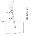
- a typical prior art endoscope 2 as illustrated in FIG. 1 , usually includes a first imaging lens (e.g., an objective) followed by a series of carrier lenses (e.g., relays) which capture and transmit an optical image from inside an enclosed area 1 to the outside.
- the proximal end of the endoscope 2 may be attached, via direct coupling or an adaptor, to a camera head 3 or an eye-piece for viewing.
- the camera head 3 usually includes lenses for receiving the optical image and forming a real optical image onto the image sensor.
- the digital image captured by the image sensor can then be transmitted to a camera control unit (CCU) or other similar modules for analysis and display.
- CCU camera control unit
- endoscopes used for FI applications, and particularly indocyanine green (ICG) applications are mainly designed and deployed for visible light imagery.
- ICG indocyanine green
- scopes To perform FI imaging, such scopes often employ an appropriate optical filter to block the stimulus light and transmit the fluoresced light.
- visible light approximately 450-650nm wavelengths
- the infrared fluorescence 800-900nm
- the user in addition to adding a filter, the user must refocus when switching between visible light mode and fluorescence mode unless the camera compensates.
- the focal differences exist because the endoscopes are not chromatically corrected for the infrared where certain fluorescence bands (particularly ICG) are located.
- What is needed are devices and methods to enable an endoscopic camera to compensate for the endoscope characteristics when the user switches between white light mode and fluorescence mode. What is further needed are devices allowing the use of varied existing endoscopes for fluorescence imaging applications without expensive and slow optical elements such as autofocus mechanisms or lenses and processing systems for chromatic aberration correction.
- an imaging apparatus in JP 2013/180120A includes an imaging unit for imaging an image of an observed subject via an object optical system, and a three-dimensional shape measuring unit for measuring a three dimensional shape of the observed subject by irradiating the subject with measurement light for distance measurement.
- the imaging unit comprises a first image pickup element for a visible light image and a second image pickup element for a fluorescent image.
- the three-dimensional shape measuring unit comprises a variable focus liquid lens.
- the variable focus liquid lens and a biaxial driving mirror constitute scanning means for scanning the measuring light with respect to the observation target. The output of a light receiving element is obtained at each scanning point, and a change of the focal length of the variable focus liquid lens related to the peak output gives a distance information of each scanning point.
- US 2010/245550 A1 discloses a fluoroscopy apparatus including an illumination port, a first image-acquisition section that acquires a fluorescence image in an observation region of an observation target, a second image-acquisition section that acquires an out-of-focus reference image of the observation target in the observation region, and an image correction section that corrects the fluorescence image using the reference image.
- the optical resolution is degraded.
- a moving mechanism for moving an image-acquisition device or a focusing lens in an optical axis direction may be provided, thus allowing a shift of the focal position of a white light beam converged to an out-of-focus state to be adjusted.
- WO 2011/113062 A1 an apparatus for presenting a stereoscopic image to a viewer is described, the apparatus comprising a stereoscopic video system with first and second image sensors for acquiring first and second images of a scene, a display system for displaying the first image to a first eye of the viewer and the second image to the second eye of the viewer, and parallax adjustment means for adjusting the parallax between the first and second images.
- US 2012/0002956 A1 describes a prior art endoscopic camera comprising a focus lens group moveable along the longitudinal axis of the camera.
- the focus lens group includes three lenses, wherein one lens is a diffractive lens, and wherein the focus is different for visible images and non-visible images and noticeable when going from capturing a fluorescence image to a visible image or vice versa.
- a minimally invasive system is claimed, wherein a camera includes a focus correction assembly including a prismatic element with a lens and the same focus lens group as in the prior art camera.
- the prismatic element splits visible light and non-visible light and the lens inside the prismatic element corrects the focus of the non-visible light, so that the focus of the non-visible image formed from the non-visible light is about the same as the focus of the visible image formed from the visible light.
- the focus corrected non-visible light and the visible light are recombined and the focus lens group focuses both combined images on an image sensor.
- a first optical device for use in endoscope procedures and operable to image in a first mode with white light and a second mode with fluoresced light outside the visible band and comprising: an image sensor assembly including one or more image sensors operable for capturing white light images and fluoresced light images; and a focus adjustment mechanism, wherein the mechanism is positioned in the first optical device and configured to automatically adjust the focus of the first optical device in switching between a first mode for white light and a second mode for fluoresced light, and wherein the automatic focus adjustment compensates for a chromatic focal difference between the white light image and the fluoresced light image caused by the dispersive or diffractive properties of optical materials or optical design employed in an assembly construction of the first optical device or an optional second optical device connected to the first optical device, or both, wherein the first optical device is a camera head that attaches to and detaches from the second optical device, and the second optical device is an endoscope, characterized in that the camera head is configured to automatically recognize the second optical device and
- a first optical device is provided for endoscopy imaging in a white light and a fluoresced light mode with an image sensor assembly including one or more image sensors.
- a focus adjustment mechanism in the first optical device to automatically adjust the focus of the first optical device wherein the automatic focus adjustment compensates for a chromatic focal difference between the white light image and the fluoresced light image caused by the dispersive or diffractive properties of the optical materials or optical design employed in an assembly construction of the first or second optical devices, or both.
- Adjustment mechanisms are provided using liquid lenses or repositioning sensors. The design may be integrated with a scope or detachable.
- a first optical device for use in endoscope procedures and operable to image in a first mode with white light and a second mode with fluoresced light outside the visible band.
- the first optical device includes an image sensor assembly including one or more image sensors operable for capturing white light images and fluoresced light images.
- a focus adjustment mechanism is positioned in the first optical device and is configured to automatically adjust the focus of the first optical device in switching between a first mode for white light and a second mode for fluoresced light, and wherein the automatic focus adjustment compensates for a chromatic focal difference between the white light image and the fluoresced light image caused by the dispersive or diffractive properties of the optical materials or optical design employed in an assembly construction of the first optical device or an optional second optical device connected to the first optical device, or both, wherein the first optical device is a camera head that attaches to and detaches from the second optical device, and the second device is an endoscope, wherein the camera head is configured to automatically recognize the second optical device and, in response, automatically apply a known, prescribed adjustment based on known characteristics of the second optical device.
- an optical assembly is positioned in the first optical device, or in the second optical device, the optical assembly including one or more optical lens elements, all either fixed in place or adjustable by manual movements, and is configured when attached to direct light received from a subject scene toward the image sensor assembly.
- a liquid-based deformable lens is provided in the first optical device optically arranged to be between the optical assembly and the image sensor and operable to automatically adjust the focus of the first optical device wherein the automatic focus adjustment compensates for a chromatic focal difference between the white light image and the fluoresced light image caused by the dispersive or diffractive properties of the optical materials or optical design employed in an assembly construction of the first optical device or the second optical device, or both.
- an optical assembly is positioned in the first optical device, or in a second optical device that attaches to the first optical device, the optical assembly including one or more optical lens elements, all either fixed in place or adjustable by manual movements, and is configured when attached to direct light received from a subject scene toward the image sensor assembly.
- the first optical device includes a mechanical device which shifts the position of at least one of the one or more image sensors when the mode is switched from white light mode to fluoresced light mode and operable to automatically adjust the focus of the first optical device wherein the automatic focus adjustment compensates for a chromatic focal difference between the white light image and the fluoresced light image caused by the dispersive or diffractive properties of the optical materials or optical design employed in an assembly construction of the first optical device or the second optical device, or both.
- the first optical device is a videoendoscope.
- the first optical device is camera head that attaches to and detaches from the second optical device, and the second optical device is an endoscope.
- the camera head is configured to automatically recognize the second optical device and, in response, automatically apply a known, prescribed adjustment based on known characteristics of the second optical device.
- the focus adjustment mechanism may include a liquid-based deformable lens.
- the device may be adapted to toggle the liquid-based deformable lens between two pre-determined states when the mode is switched from white light mode to fluoresced light mode.
- the sensor position may toggle between two pre-determined positions when the mode is switched from white light mode to fluoresced light mode.
- the focus adjustment includes a mechanical device which shifts the position of at least one of the one or more image sensors when the mode is switched from white light mode to fluoresced light mode.
- the mechanical device may be a motor, such as a piezoelectric motor.
- the device is adapted to trigger the automatic focus adjustment when the device is toggled between white light mode and fluorescence mode.
- the first device may include an electronic controller having tangible, non-transitory computer memory holding program code executable to control the various adjustments, and to trigger the automatic focus adjustment when the device is toggled.
- Implementations of the disclosure may also be embodied as software or firmware, stored in a suitable medium, and executable to perform various versions of the methods herein.
- the program code is executable to control the various adjustments, and to trigger the automatic focus adjustment when the device is toggled.
- the functionality described herein for the implementations of the first aspect may be embodied as a method or process for operating an imaging scope to perform the automatic focus adjustment.
- the method which does not fall within the scope of the claimed subject-matter, may include automatically recognizing the connection of an endoscope device to a camera head embodying the first optical device.
- the method may retrieve focus settings for the different modes from memory, and may store focus settings for multiple devices.
- the method applies the retrieved focus settings and allows procedures to be conducted in the white light imaging mode.
- the method applies retrieved focus settings for the fluorescence imaging mode according to any of the different device aspects of the invention. Then the method allows procedures in the fluorescence imaging mode, and allows the modes to be toggled as needed with the appropriate focus settings applied for each toggle.
- first elements e.g., sensors and lenses
- first elements that are "optically arranged" in relation to other elements
- a lens group optically arranged between an image sensor and an objective means that the lens group occupies a portion of the optical path that light travels (e.g., from the objective to the image sensor) for capturing images or video.
- FIG. 2 shows cross section diagram of a video endoscope device according to an example embodiment of the invention.
- This device includes a first optical device 108 (in this version "camera head 108") connected in a detachable manner to endoscope 107 ("second optical device") which is connected to in a detachable manner as known in the art.
- Endoscope 107 includes a shaft 106.
- Other versions may, of course, include a scope integrated with the camera head or in a single first optical device.
- Various structural components supporting the depicted elements are omitted in the diagram, as well as other components such as illumination light sources, fluorescent excitation light sources, and controls, which are known in the art and are not shown in order to avoid obscuring the relevant details of the example embodiments of the invention.
- cover glass 202 which in this version faces directly along the longitudinal axis of the shaft 106, but may also be positioned at an angle relative to the longitudinal axis as is known in the art. Behind the cover glass 202 is shown a preferred position for the wide angle lens 204, set against or very near cover glass 202 and preferably assembled together with the cover glass in construction. While a wide angle lens is shown, this is not limiting and any suitable lens may be used in various embodiments. Further, the particular number and arrangement of lenses in the endoscope shaft 106 will vary widely depending on the application.
- a second lens or lens group 208 Optically arranged or attached at the proximal side of lens 204 is a second lens or lens group 208 to focus the incoming light to an appropriate size for the imaging process receiving the incoming light downstream in the proximal direction.
- the directed light then passes along endoscope shaft 106, and may be guided by other optical elements such as rod lenses.
- the light is received at a doublet lens 210, and directed toward first optical device 108, where it passes through the proximal window 212 of the endoscope 107 and the distal window 213 of first optical device 108.
- One or more additional lens groups or rod lenses may be included optically positioned between doublet lens 210 and focusing lens group 214. In versions with a unified device, such windows may not be used.
- Focusing lens group 214 focuses the image light toward the image sensor assembly 215 which may include a cover glass 221 and image sensor 222.
- image sensor 222 is repositionable along the focal path by an adjustment mechanism 224, which may be a piezo-electric motor or other suitable adjustment mechanism. Adjustment mechanism 224 is shown mechanically coupled to sensor 222 with a rod 225, which pushes or pulls image sensor 222 to achieve the adjustment movement. Image sensor 222 may be held in a frame having guide rails or other suitable structure to stabilize the orientation during movement. In this version, image sensor 222 is a single sensor capable of detecting both visible light images and fluoresced light images, for example visible light imagery at approximately the 450-650nm wavelengths, and the infrared fluorescence imagery at 800-900nm.
- the senor may detect other fluorescent wavelengths commonly used in endoscopic imagery in addition to the visible light wavelengths. Because the fluorescent imagery is focused in a different plane than the visible light, the device has the capability of adjusting the optical path focus when switching between visible light mode, as shown in the image sensor 222 first white light image position depicted as a solid box, and the second fluorescence mode image position depicted by the dotted box.
- the chromatic focal difference in the optical path are depicted by the two ray trace lines shown on the diagram, with the visible light ray trace 226 shown focused on the sensor 222 in the first depicted position in visible light mode, and the FI light ray trace 227 shown focused on sensor 222 in the FI mode position.
- the slight chromatic focal difference can be seen as the rays diverge slightly over the course of the optical path.
- the distance that image sensor 222 is moved, shown as D, is for adjusting the focal length of the optical path between white light imaging mode and fluorescent imaging mode. Typically this distance may be around 2mm of movement, but this will vary depending on the total channel length and the chromatic characteristics of the optical elements in the optical channel.
- the adjustment mechanism 224 is positioned in the first optical device 108 to automatically adjust the focus of the first optical device where the automatic focus adjustment compensates for a chromatic focal difference between the white light image and the fluoresced light image caused by the dispersive or diffractive properties of the optical materials or optical design employed in the assembly construction of the first or second optical devices, or both.
- the optical assembly includes optical lenses all either fixed in place or adjustable by manual movements.
- the act of a user changing modes to toggle between white light mode and fluorescence mode triggers an autofocus algorithm controlling the movement of adjustment mechanism 224.
- Preset positions may be employed for both modes to achieve the desired position, as further described below, avoiding the need for autofocus processing to achieve the known desired focal length for each of the modes.
- FIG. 3 is a cross section diagram of an optical channel 300 for use in a video endoscopic system according to another embodiment, which employs a deformable lens to adjust the focus.
- the depicted optical channel 300 may be embodied in first and second optical devices 107 and 108, such as the camera head and endoscope discussed above, or a single integrated optical device.
- the assembly construction of the second optical device, or the endoscope and shaft portion of an integrated device, may vary.
- the optical channel includes an objective passing the observed image light to one or more lens groups 208.
- the light is directed along the channel through a suitable lens arrangement such as doublet lens 210, and in detachable dual-device embodiments passes through windows 212 and 213 to the first optical device 108.
- the deformable lens 302 is deformable to adjust the optical channel focal length for the same purpose of changing modes between white light imaging and fluorescence imaging, as discussed with regard to the other embodiments.
- the deformable lens can be made of, for example, birefringent liquid crystal, a transparent elastic membrane filled with fluid, or a two fluid interface.
- a liquid-based deformable lens is employed, but other suitable deformable lens technologies may be used. Depicted are two different deformable surface configurations for the deformable lens.
- deformable lens 302 is configured with the deformable surface at position 306, which generally has more negative lens power than the second fluoresced light configuration position of the deformable lens surface shown at dotted line 308.
- the deformable lenses can be tuned at least in part by a suitable adjustment mechanism (not shown) such as an electrostatic actuator, an electromagnetic actuator, a piezo-motor, a magneto-strictive actuator, a stepper motor, or an electroactive polymer actuator for a high focus tuning range.
- a suitable adjustment mechanism such as an electrostatic actuator, an electromagnetic actuator, a piezo-motor, a magneto-strictive actuator, a stepper motor, or an electroactive polymer actuator for a high focus tuning range.
- the white light configuration position 306 is a negative power lens
- the fluoresced light confirmation position 308 is a positive power lens, however this is not limiting, and they may both be negative or both may be positive depending on the optical channel design.
- the white light mode will have a comparatively negative lens power than the fluoresced light mode.
- the deformable lens 302 with its adjustment mechanism is arranged in the first optical device 108 to automatically adjust the focus of the first optical device where the automatic focus adjustment compensates for a chromatic focal difference between the white light image and the fluoresced light image caused by the dispersive or diffractive properties of the optical materials or optical design employed in the assembly construction of the first or second optical devices, or both.
- the act of a user changing modes to toggle between white light mode and fluorescence mode triggers an autofocus algorithm controlling the movement of adjustment mechanism 224.
- This design also may be accomplished even for endoscope designs in which the optical assembly includes optical lenses all either fixed in place or adjustable by manual movements. Preset positions may be employed for both modes to achieve the desired position, as further described below, avoiding the need for autofocus processing to achieve the known desired focal length for each of the modes.
- deformable lens 302 may be placed in any suitable location in the optical channel where the channel construction can accommodate the varied focal lengths resulting from changing the deformable lens configuration.
- deformable lens 302 may be part of the focusing lens group 214.
- the image light passes to the focusing lens assembly 214, which is similar to that described with respect to FIG. 2 , and then through the image sensor cover glass 221 and finally to the image sensor 222. Note that in this version the image sensor is fixed in position relative to the optical channel.
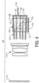
- FIG. 4 is a cross section diagram of a partial optical channel according to another embodiment.
- the diagram shows only the portion of the optical channel in first optical device 108, which is preferably a camera head device.
- first optical device 108 which is preferably a camera head device.
- the diagram represents the proximal portion of the optical channel including the focusing lens group and the image sensor.
- the depicted system uses a light splitter 402 to direct the visible image light to image sensor 222 and the fluoresced light to fluorescence image sensor 223. This is illustrated with the depicted light bundle traces 230 in which the fluorescence bundle traces 231 light enters and is passed through the dichroic prism interface of light splitter 402 and hits fluorescence image sensor 223, while the visible light bundle traces 232 are reflected downward and hit image sensor 222.
- Light splitter 402 is preferably a dichroic prism or other suitable dichroic optical element, having a long-pass reflective surface at a 45 degree angle allowing longer wavelengths to pass through to fluorescence image sensor 223 and shorter wavelengths to reflect to sensor 222.
- the cutoff wavelength may be selected to be at or near the longest wavelength of visible light, that is near 650nm, or longer as long as the cutoff is shorter than the shortest wavelength required for detection of the fluoresced light. While this version reflects the visible light wavelengths 232 and passes the fluoresced light wavelengths 231, this is not limiting and other versions may pass the visible light and reflect the fluoresced light (with a short-pass dichroic prism, for example), or may reflect both in differing directions.
- Image sensor 222 is capable of detecting the visible light wavelengths commonly used for endoscopic examination, for example visible light imagery at approximately the 450-650nm wavelengths.
- image sensor 223 is a single sensor capable of detecting fluoresced light images, infrared fluorescence imagery at 800-900nm. Additionally or alternatively the sensor may detect other fluorescent wavelengths commonly used in endoscopic imagery.
- fluorescence imaging sensor 223 is repositionable along the focal path by an adjustment mechanism 224 in order to adjust the focal plane for the fluoresced light based on characteristics of the attached endoscope, such as the aberration characteristics or the use of a differing fluoresced wavelengths in differing scopes for use with various fluoresced imaging techniques.
- This design also may be accomplished even for endoscope designs in which the optical assembly includes optical lenses all either fixed in place or adjustable by manual movements.
- the adjustment mechanism may be a piezo-electric motor or other suitable adjustment mechanism as discussed above with regard to the embodiment of FIG. 2 . Similarly to the embodiment of FIG.
- adjustment mechanism 224 is shown mechanically coupled to image sensor 223 with a rod 225, which pushes or pulls image sensor 223 to achieve the adjustment movement.
- Image sensor 223 may be held in a frame having guide rails or other suitable structure to stabilize the orientation during movement.
- the distance adjusted, shown as distance D, in this version will typically be less than that required to adjust for differing focal lengths between visible and fluoresced light, because this embodiments adjusts only for different fluoresced light characteristics of the optical channel such as dispersion and chromatic focal differences.
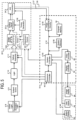
- FIG. 5 a block diagram of system including an image capture device according to an example embodiment of the invention is shown.
- the invention is applicable to more than one type of device enabled for image capture, such as endoscopes incorporating solid state imagers, digital microscopes, digital cameras, mobile phones equipped with imaging sub-systems, and automotive vehicles equipped with imaging sub-systems, for example.
- the preferred version is an imaging scope system, such as an endoscope.
- a light source 8 illuminates subject scene 9 with visible light and/or fluorescent excitation light, which may be outside the visible spectrum in the ultra-violet range or the infra-red/near infrared range, or both.
- Light source 8 may include a single light emitting element configured to provide light throughout the desired spectrum, or a visible light emitting element and a one or more fluorescent excitation light emitting elements. Further, light source 8 may include fiber optics passing through the body of the scope, or other light emitting arrangements such as LEDs or laser diodes positioned at or near the front of the scope.
- light 10 reflected from (or, alternatively, as in the case of fluorescence, excitation light 8 absorbed and subsequently emitted by) the subject scene is input to an optical assembly 11, where the light is focused to form an image at a solid-state image sensor(s) 222 and/or fluoresced light sensor(s) 223.
- Optical assembly 11 includes at least one lens, which may be a wide-angle lens element such that optical assembly 11 focuses light which represents a wide field of view.
- the deformable lens 302 is part of the optical assembly.
- portions of the optical assembly may be embodied in a camera head or other first optical device, while other portions are in an endoscope or other scope device, or the optical assembly 11 may contained in a single imaging device.
- Image sensor 222 which may include separate R, G, and B sensor arrays
- fluoresced light sensor 223 convert the incident visible and invisible light to an electrical signal by integrating charge for each picture element (pixel).
- fluoresced light sensor 223 is shown as an optional dotted box because embodiments may use the RGB image sensor 222 to detect only white light images or to also detect fluoresced light (e.g., NIR, ICG, FI). The latter scheme may be used when the fluoresced light is in a spectrum detectable by image sensor 222 that is in or near the visible light spectrum typically detected by a RGB sensor arrays.
- fluoresced light sensor 223 is shown as an optional dotted box because embodiments may use the RGB image sensor 222 to detect only white light images or to also detect fluoresced light (e.g., NIR, ICG, FI). The latter scheme may be used when the fluoresced light is in a spectrum detectable by image sensor 222 that is in or near the visible light spectrum typically detected by a RGB sensor arrays.
- the image sensor 222 and fluoresced light sensor 223 may be active pixel complementary metal oxide semiconductor sensor (CMOS APS) or a charge-coupled device (CCD).
- CMOS APS active pixel complementary metal oxide semiconductor sensor
- CCD charge-coupled device
- the total amount of light 10 reaching the image sensor 222 and/or fluoresced light sensor 223 is regulated by the light source 8 intensity, the optical assembly 11 aperture, and the time for which the image sensor 222 and fluoresced light sensor 223 integrates charge.
- An exposure controller 40 responds to the amount of light available in the scene given the intensity and spatial distribution of digitized signals corresponding to the intensity and spatial distribution of the light focused on image sensor 222 and fluoresced light sensor 223.
- Exposure controller 40 also controls the emission of fluorescent excitation light from light source 8, and may control the visible and fluorescent light emitting elements to be on at the same time, or to alternate to allow fluoresced light frames to be captured in the absence of visible light if such is required by the fluorescent imaging scheme employed. Exposure controller 40 may also control the optical assembly 11 aperture, and indirectly, the time for which the image sensor 222 and fluoresced light sensor 223 integrate charge. The control connection from exposure controller 40 to timing generator 26 is shown as a dotted line because the control is typically indirect.
- exposure controller 40 has a different timing and exposure scheme for each of sensors 222 and 223. Due to the different types of sensed data, the exposure controller 40 may control the integration time of the sensors 222 and 223 by integrating sensor 222 up to the maximum allowed within a fixed 60Hz or 50Hz frame rate (standard frame rates for USA versus European video, respectively), while the fluoresced light sensor 223 may be controlled to vary its integration time from a small fraction of sensor 222 frame time to many multiples of sensor 222 frame time.
- the frame rate of sensor 222 will typically govern the synchronization process such that images frames based on sensor 223 are repeated or interpolated to synchronize in time with the 50 or 60 fps rate of sensor 222.
- Analog signals from the image sensor 222 and fluoresced light sensor 223 are processed by analog signal processor 22 and applied to analog-to-digital (A/D) converter 24 for digitizing the analog sensor signals.
- the digitized signals each representing streams of images or image representations based on the data, are fed to image processor 30 as image signal 27, and first fluorescent light signal 29.
- image processor 30 For versions in which the image sensor 222 also functions to detect the fluoresced light, fluoresced light data is included in the image signal 27, typically in one or more of the three color channels.
- An adjustment control circuit 20 may be provided for supplying the driving signals to operate the adjustment mechanism according to the various embodiments herein.
- the adjustment control circuit sends appropriate driving signals to the mechanical adjustment mechanism, such as the piezo-electric motor, and may also receive position signals back from the adjustment mechanism.
- adjustment control circuitry 20 sends appropriate drive signals to the deformable lens adjustment mechanism, such as an actuator or piezo-electric motor, and may also receive position signals from the adjustment mechanism.
- Image processing circuitry 30 includes circuitry performing digital image processing functions to process and filter the received images as is known in the art. Image processing circuitry may include separate, parallel pipelines for processing the visible light image data and the FI image data separately.
- image processing circuitry 30 may also perform known autofocus algorithms to allow feedback control of adjustment control circuitry 20 to compensate for chromatic focal difference between the white light image and the fluoresced light image.
- image processing circuitry 30 may also perform known autofocus algorithms to allow feedback control of adjustment control circuitry 20 to compensate for chromatic focal difference between the white light image and the fluoresced light image.
- adjustments are pre-determined and stored in system memory 56 to allow quick and reliable focus adjustment.
- the predetermined settings may be stored in memory in the first optical device itself rather than a CCM or other attached controller.
- Image processing circuitry 30 may provide algorithms, known in the art, for combining visible light imagery with FI imagery in a combined image display, and further highlighting or emphasizing the FI imagery for easily distinguishing the presence of fluorescing features in the image.
- Timing generator 26 produces various clocking signals to select rows and pixels and synchronizes the operation of image sensor 222 and fluorescent sensor 223, analog signal processor 22, and A/D converter 24.
- Image sensor assembly 28 includes the image sensor 222 and fluorescent sensor 223, adjustment control 20, the analog signal processor 22, the A/D converter 24, and the timing generator 26.
- the functional elements of the image sensor assembly 28 can be fabricated as a single integrated circuit as is commonly done with CMOS image sensors or they can be separately-fabricated integrated circuits.
- the system controller 50 controls the overall operation of the image capture device based on a software program stored in program memory 54.
- This memory can also be used to store user setting selections and other data to be preserved when the camera is turned off.
- System controller 50 controls the sequence of data capture by directing exposure controller 40 to set the light source 8 intensity, the optical assembly 11 aperture, and controlling various filters in optical assembly 11 and timing that may be necessary to obtain image streams based on the visible light and fluoresced light.
- optical assembly 11 includes an optical filter configured to attenuate excitation light and transmit the fluoresced light.
- a data bus 52 includes a pathway for address, data, and control signals.
- Processed image data are continuously sent to video encoder 80 to produce a video signal.
- This signal is processed by display controller 82 and presented on image display 88.
- This display is typically a liquid crystal display backlit with light-emitting diodes (LED LCD), although other types of displays are used as well.
- the processed image data can also be stored in system memory 56 or other internal or external memory device.
- the user interface 60 including all or any combination of image display 88, user inputs 64, and status display 62, is controlled by a combination of software programs executed on system controller 50.
- User inputs typically include some combination of typing keyboards, computer pointing devices, buttons, rocker switches, joysticks, rotary dials, or touch screens.
- the system controller 50 manages the graphical user interface (GUI) presented on one or more of the displays (e.g. on image display 88).
- System controller 50 may receive inputs from buttons or other external user interface controls on the scope itself (or software controls through the GUI) to receive inputs to control the process for automatically adjusting the focus according to the present invention.
- GUI graphical user interface
- system controller 50 will typically have a mode toggle user input (typically through a button on the endoscope or camera head itself, but possibly through a GUI interface), and in response transmit commands to adjust image processing circuitry 30 based on predetermined setting stored in system memory.
- a mode toggle user input typically through a button on the endoscope or camera head itself, but possibly through a GUI interface
- Such settings may include different settings for different models of scopes that may be attached to a camera head or other imaging device containing image sensor assembly 28.
- Image processing circuitry 30 is one of three programmable logic devices, processors, or controllers in this embodiment, in addition to a system controller 50 and the exposure controller 40.
- Image processing circuitry 30, controller 50, exposure controller 40, system and program memories 56 and 54, video encoder 80 and display controller 82 may be housed within camera control module (CCM) 70.
- CCM camera control module
- CCM 70 may be responsible for powering and controlling light source 8, image sensor assembly 28, and/or optical assembly 11.
- a separate front end camera module may perform some of the image processing functions of image processing circuitry 30.
- these programmable logic devices, processors, or controllers can be combinable in various ways without affecting the functional operation of the imaging device and the application of the invention.
- These programmable logic devices, processors, or controllers can comprise one or more programmable logic devices, digital signal processor devices, microcontrollers, or other digital logic circuits. Although a combination of such programmable logic devices, processors, or controllers has been described, it should be apparent that one programmable logic device, digital signal processor, microcontroller, or other digital logic circuit can be designated to perform all of the needed functions. All of these variations can perform the same function and fall within the scope of this invention.
- FIG. 6 is a flowchart of a process for controlling the automatic focus adjustment according to the present disclosure but not falling within the scope of the claimed subject-matter.
- the process may include attaching a new endoscope or other scope device to a first optical device such as a camera head at block 602, or powers on the first optical device which may have a new scope attached. Some versions may not include the steps of blocks 602 and 604.
- the first optical device alone or in cooperation with an attached CCM, recognizes the model of new scope has been attached, or the user selects through the CCM GUI the model of scope attached. The recognition may happen with any suitable means such as an RFID tag being recognized, or a serial number or other identifier being read from the second optical device, the scope, by the first optical device.
- the process retrieves focus settings for the different available visible light and FI modes from memory as shown by arrows 605 and 607.
- the memory may hold focus settings for multiple scope models, including known, prescribed adjustments to provide the desired focal settings for each scope.
- the focus settings typically include control information for the automatic adjustment mechanism, such as actuator or piezo-electric motor positions for controlling the deformable lens or the sensor positioning mechanism as described above.
- control information for the automatic adjustment mechanism such as actuator or piezo-electric motor positions for controlling the deformable lens or the sensor positioning mechanism as described above.
- such memory may be connected to a controller aboard the first optical device.
- the memory will typically be system memory 56 of the system CCM as shown, however onboard memory may be used in this case as well.
- the step of retrieving the settings may be performed by the CCM or the first optical device.
- the first optical device applies the focus settings for the mode in which the first optical device is currently set, in this example the visible light mode is shown applied first. Then the first optical device may be used to conduct examination procedures as shown at block 610.
- the user changes the mode to an alternate mode, in this case selecting the FI mode. This is typically done through a button or switch, or a foot pedal, on the first optical device but may be done through the CCM GUI.
- the process applies the settings for FI mode, adjusting the sensor position or deformable lens as described above. This may involve another retrieval from memory or all mode settings may be held in working memory on the device or CCM. Then the device may be used to conduct examination procedures at block 616.
- the process may also include applying settings to change between different FI modes with different fluoresced light wavelengths.
- the FI mode may include simultaneous dual imaging with visible light images as discussed above.
- the modes may be toggled as needed with each change of mode applying the appropriate focus settings.
- the process may be conducted by program code running on system controller 50 on a system CCM, or may be conducted under control of program code or digital logic such as FPGA circuitry embodied in adjustment control circuitry 20 on the first optical device.
Landscapes
- Health & Medical Sciences (AREA)
- Life Sciences & Earth Sciences (AREA)
- Surgery (AREA)
- Physics & Mathematics (AREA)
- Optics & Photonics (AREA)
- Engineering & Computer Science (AREA)
- Biomedical Technology (AREA)
- Veterinary Medicine (AREA)
- Biophysics (AREA)
- Pathology (AREA)
- Radiology & Medical Imaging (AREA)
- Nuclear Medicine, Radiotherapy & Molecular Imaging (AREA)
- Public Health (AREA)
- Heart & Thoracic Surgery (AREA)
- Medical Informatics (AREA)
- Molecular Biology (AREA)
- Animal Behavior & Ethology (AREA)
- General Health & Medical Sciences (AREA)
- General Physics & Mathematics (AREA)
- Multimedia (AREA)
- Astronomy & Astrophysics (AREA)
- Signal Processing (AREA)
- Endoscopes (AREA)
- Instruments For Viewing The Inside Of Hollow Bodies (AREA)
Claims (13)
- Erste optische Vorrichtung (108) zur Verwendung bei Endoskopverfahren und betriebsfähig, um in einem ersten Modus mit Weißlicht und einem zweiten Modus mit fluoreszierendem Licht außerhalb des sichtbaren Bands abgebildet zu werden, und umfassend:eine Bildsensoranordnung (28, 215), die einen oder mehrere Bildsensoren (222, 223) einschließt, die zum Aufnehmen von Weißlichtbildern und Bildern mit fluoreszierendem Licht betriebsfähig sind; undeinen Fokuseinstellungsmechanismus (224, 302), wobei der Mechanismus (224, 302) in der ersten optischen Vorrichtung (108) positioniert und konfiguriert ist, um den Fokus der ersten optischen Vorrichtung (108) bei einem Umschalten zwischen einem ersten Modus für Weißlicht und einem zweiten Modus für fluoreszierendes Licht automatisch einzustellen, und wobei die automatische Fokuseinstellung einen chromatischen Fokusunterschied zwischen dem Weißlichtbild und dem Bild mit fluoreszierendem Licht kompensiert, der durch die dispersiven oder diffraktiven Eigenschaften optischer Materialien oder eines optischen Designs verursacht wird, das in einer Anordnungskonstruktion der ersten optischen Vorrichtung (108) oder einer optionalen zweiten optischen Vorrichtung, die mit der ersten optischen Vorrichtung (108) verbunden ist, oder beider eingesetzt wird, wobei die erste optische Vorrichtung (108) ein Kamerakopf (108) ist, der an die zweite optische Vorrichtung anheftet und sich von dieser löst, und die zweite optische Vorrichtung ein Endoskop (107) ist, wobei der Kamerakopf (108) konfiguriert ist, um die zweite optische Vorrichtung automatisch zu erkennen und, als Reaktion darauf, eine bekannte, vorgeschriebene Einstellung basierend auf bekannten Charakteristiken der zweiten optischen Vorrichtung automatisch anzuwenden.
- Vorrichtung nach Anspruch 1, wobei die erste optische Vorrichtung (108) ein Kamerakopf eines Videoendoskops ist.
- Vorrichtung nach einem der Ansprüche 1 oder 2, wobei die Fokuseinstellung, die durch den Fokuseinstellungsmechanismus (224, 302) automatisch eingestellt wurde, eine bekannte, vorgeschriebene Einstellung basierend auf den bekannten Charakteristiken der ersten optischen Vorrichtung (108) und/oder der zweiten optischen Vorrichtung ist.
- Vorrichtung nach einem der Ansprüche 1 bis 3, wobei der Fokuseinstellungsmechanismus (224, 302) eine flüssigkeitsbasierte verformbare Linse (302) umfasst.
- Vorrichtung nach Anspruch 4, wobei die Vorrichtung angepasst ist, um die flüssigkeitsbasierte verformbare Linse (302) zwischen zwei zuvor bestimmten Zuständen hin- und herzuschalten, wenn der Modus von dem Weißlichtmodus in den Modus des fluoreszierenden Lichts umgeschaltet wird.
- Vorrichtung nach Anspruch 4 oder 5, ferner umfassend eine optische Anordnung (11), die in der ersten optischen Vorrichtung (108) oder in der zweiten optischen Vorrichtung, die an die erste optische Vorrichtung (108) anheftet, positioniert ist, wobei die optische Anordnung (11) ein oder mehrere optische Linsenelemente einschließt, die alle entweder an ihrem Platz befestigt oder durch manuelle Bewegungen einstellbar sind, und konfiguriert sind, um Licht, das von einer Motivszene empfangen wird, zu der Bildsensoranordnung (28, 215) hin zu lenken, und wobei die flüssigkeitsbasierte verformbare Linse (302) in der ersten optischen Vorrichtung (108) optisch eingerichtet ist, um sich zwischen der optischen Anordnung (11) und dem Bildsensor (222, 223) zu befinden.
- Vorrichtung nach einem der Ansprüche 1 bis 6, wobei die automatische Fokuseinstellung eine mechanische Vorrichtung umfasst, die die Position von mindestens einem des einen oder der mehreren Bildsensoren (222, 223) verschiebt, wenn der Modus von dem Weißlichtmodus in den Modus des fluoreszierenden Lichts umgeschaltet wird.
- Vorrichtung nach Anspruch 7, wobei die mechanische Vorrichtung ein Motor ist.
- Vorrichtung nach Anspruch 8, wobei der Motor ein piezoelektrischer Motor ist.
- Vorrichtung nach einem der Ansprüche 7 bis 9, wobei die Sensorposition zwischen zwei zuvor bestimmten Positionen hin- und herschaltet, wenn der Modus von dem Weißlichtmodus in den Modus des fluoreszierenden Lichts umgeschaltet wird.
- Vorrichtung nach einem der Ansprüche 7 bis 10, ferner umfassend eine optische Anordnung (11), die in der ersten optischen Vorrichtung (108) oder in der zweiten optischen Vorrichtung, die an die erste optische Vorrichtung (108) anheftet, positioniert ist, wobei die optische Anordnung (11) ein oder mehrere optische Linsenelemente einschließt, die alle entweder an ihrem Platz befestigt oder durch manuelle Bewegungen einstellbar sind, und konfiguriert sind, um Licht, das von einer Motivszene empfangen wird, zu der Bildsensoanordnung (28, 215) hin zu lenken, und wobei die mechanische Vorrichtung die Position von mindestens einem des einen oder der mehreren Bildsensoren (222, 223) verschiebt.
- Vorrichtung nach einem der Ansprüche 7 bis 11, ferner umfassend einen dichroitischen Lichtteiler (402), um das sichtbare Licht (232) auf einen Bildsensor (222) der Bildsensoranordnung (28, 215) zu richten und das fluoreszierende Licht außerhalb des sichtbaren Bands (231) auf einen zweiten Bildsensor (223) der Bildsensoranordnung (28, 215) zu richten, und wobei die mechanische Vorrichtung (224) die Position des Bildsensors (223) des fluoreszierenden Lichts verschiebt.
- Vorrichtung nach einem der Ansprüche 1 bis 12, wobei die Vorrichtung angepasst ist, um die automatische Fokuseinstellung auszulösen, wenn die Vorrichtung zwischen dem Weißlichtmodus und dem Modus des fluoreszierenden Lichts hin- und hergeschaltet wird.
Applications Claiming Priority (1)
| Application Number | Priority Date | Filing Date | Title |
|---|---|---|---|
| US15/636,345 US11432712B2 (en) | 2017-06-28 | 2017-06-28 | Fluorescence imaging scope with dual mode focusing structures |
Publications (2)
| Publication Number | Publication Date |
|---|---|
| EP3420880A1 EP3420880A1 (de) | 2019-01-02 |
| EP3420880B1 true EP3420880B1 (de) | 2025-02-12 |
Family
ID=62712706
Family Applications (1)
| Application Number | Title | Priority Date | Filing Date |
|---|---|---|---|
| EP18000533.2A Active EP3420880B1 (de) | 2017-06-28 | 2018-06-18 | Fluoreszenzabbildungsbereich mit doppelmodus-fokussierungsstrukturen |
Country Status (2)
| Country | Link |
|---|---|
| US (2) | US11432712B2 (de) |
| EP (1) | EP3420880B1 (de) |
Families Citing this family (15)
| Publication number | Priority date | Publication date | Assignee | Title |
|---|---|---|---|---|
| US11832797B2 (en) * | 2016-09-25 | 2023-12-05 | Micronvision Corp. | Endoscopic fluorescence imaging |
| US10571679B2 (en) * | 2017-01-06 | 2020-02-25 | Karl Storz Imaging, Inc. | Endoscope incorporating multiple image sensors for increased resolution |
| EP4365657A3 (de) * | 2018-05-02 | 2024-07-31 | Stryker Corporation | Autofokus mit flüssiglinse zur visualisierung endoskopischer chirurgie |
| WO2020210168A1 (en) * | 2019-04-08 | 2020-10-15 | Activ Surgical, Inc. | Systems and methods for medical imaging |
| US12292564B2 (en) | 2019-04-08 | 2025-05-06 | Activ Surgical, Inc. | Systems and methods for medical imaging |
| DE102019115302A1 (de) * | 2019-06-06 | 2020-12-10 | Olympus Winter & Ibe Gmbh | Umkehrsatz für Endoskop und Endoskop |
| EP4017340A4 (de) | 2019-08-21 | 2023-12-13 | Activ Surgical, Inc. | Systeme und verfahren zur medizinischen bildgebung |
| DE102020105459A1 (de) * | 2020-03-02 | 2021-09-02 | Karl Storz Se & Co. Kg | Medizinische bildgebungsvorrichtung mit mehreren bildgebungsmodi |
| US12089802B2 (en) * | 2020-03-17 | 2024-09-17 | Sony Olympus Medical Solutions Inc. | Medical image processing apparatus and medical observation system |
| JP2021145823A (ja) * | 2020-03-18 | 2021-09-27 | ソニー・オリンパスメディカルソリューションズ株式会社 | 医療用制御装置及び医療用観察システム |
| JP7452177B2 (ja) * | 2020-03-27 | 2024-03-19 | ソニーグループ株式会社 | 医療用観察システム、制御装置、制御方法、および撮像装置 |
| US12231749B2 (en) * | 2021-07-29 | 2025-02-18 | Meta Platforms Technologies, Llc | Sensing with liquid crystal polarization holograms and metasurface |
| US20230240536A1 (en) * | 2022-01-28 | 2023-08-03 | Visionsense Ltd. | Endoscope camera assembly |
| US12239409B2 (en) | 2022-02-28 | 2025-03-04 | Visionsense Ltd. | Fluorescence imaging camera assembly for open surgery |
| CN119548079A (zh) * | 2024-10-29 | 2025-03-04 | 青岛海信电子技术服务有限公司 | 一种内窥镜摄像手柄 |
Citations (1)
| Publication number | Priority date | Publication date | Assignee | Title |
|---|---|---|---|---|
| US20120002956A1 (en) * | 2010-07-02 | 2012-01-05 | Mcdowall Ian | Dual optical path prism and camera in a minimally invasive surgical system |
Family Cites Families (17)
| Publication number | Priority date | Publication date | Assignee | Title |
|---|---|---|---|---|
| US8194122B2 (en) * | 2002-03-12 | 2012-06-05 | Karl Storz Imaging, Inc. | Universal scope reader |
| JP2005284136A (ja) | 2004-03-30 | 2005-10-13 | Olympus Corp | 観察装置および観察装置の焦点合わせ方法 |
| US7796243B2 (en) | 2004-06-09 | 2010-09-14 | National Research Council Of Canada | Detection and monitoring of changes in mineralized tissues or calcified deposits by optical coherence tomography and Raman spectroscopy |
| US20060012836A1 (en) * | 2004-07-16 | 2006-01-19 | Christian Boemler | Focus adjustment for imaging applications |
| WO2007106624A2 (en) * | 2006-02-07 | 2007-09-20 | Novadaq Technologies Inc. | Near infrared imaging |
| US8982203B2 (en) * | 2007-06-06 | 2015-03-17 | Karl Storz Gmbh & Co. Kg | Video system for viewing an object on a body |
| EP2051051B1 (de) | 2007-10-16 | 2020-06-03 | Cambridge Research & Instrumentation, Inc. | Spektralbildgebungssystem mit dynamischer optischer Korrektur |
| US20090236541A1 (en) * | 2008-03-24 | 2009-09-24 | General Electric Company | System and Methods for Optical Imaging |
| WO2010042522A1 (en) | 2008-10-06 | 2010-04-15 | Novadaq Technologies Inc. | Compensating optical coupler for visible and nir imaging |
| JP5443802B2 (ja) * | 2009-03-24 | 2014-03-19 | オリンパス株式会社 | 蛍光観察装置 |
| ES2688280T3 (es) | 2010-03-12 | 2018-10-31 | Viking Systems, Inc. | Sistema de visualización estereoscópica |
| KR101204096B1 (ko) * | 2011-01-28 | 2012-11-22 | 삼성테크윈 주식회사 | 이미지 센서 모듈 및 이를 구비한 카메라 모듈 |
| US8784301B2 (en) * | 2011-08-12 | 2014-07-22 | Intuitive Surgical Operations, Inc. | Image capture unit and method with an extended depth of field |
| JP5975562B2 (ja) * | 2012-03-02 | 2016-08-23 | オリンパス株式会社 | 撮像装置及び撮像装置の作動方法 |
| WO2014144286A1 (en) | 2013-03-15 | 2014-09-18 | Convergent Dental, Inc. | System and method for optical imaging, magnification, fluorescence, and reflectance |
| WO2014199980A1 (ja) * | 2013-06-12 | 2014-12-18 | オリンパスメディカルシステムズ株式会社 | 内視鏡システム |
| US9945777B2 (en) * | 2016-01-14 | 2018-04-17 | Hand Held Products, Inc. | Multi-spectral imaging using longitudinal chromatic aberrations |
-
2017
- 2017-06-28 US US15/636,345 patent/US11432712B2/en active Active
-
2018
- 2018-06-18 EP EP18000533.2A patent/EP3420880B1/de active Active
-
2022
- 2022-07-28 US US17/875,407 patent/US20220361737A1/en not_active Abandoned
Patent Citations (1)
| Publication number | Priority date | Publication date | Assignee | Title |
|---|---|---|---|---|
| US20120002956A1 (en) * | 2010-07-02 | 2012-01-05 | Mcdowall Ian | Dual optical path prism and camera in a minimally invasive surgical system |
Also Published As
| Publication number | Publication date |
|---|---|
| US20190000308A1 (en) | 2019-01-03 |
| US11432712B2 (en) | 2022-09-06 |
| EP3420880A1 (de) | 2019-01-02 |
| US20220361737A1 (en) | 2022-11-17 |
Similar Documents
| Publication | Publication Date | Title |
|---|---|---|
| EP3420880B1 (de) | Fluoreszenzabbildungsbereich mit doppelmodus-fokussierungsstrukturen | |
| US11786115B2 (en) | Method and apparatus to generate hyperspectral image data with a medical imaging device | |
| US8602979B2 (en) | Electronic endoscope having front-view and side-view image capturing | |
| US8773765B2 (en) | Endoscope apparatus | |
| EP3584623B1 (de) | Medizinische bildgebungsvorrichtung mit geteiltem bild auf einem gemeinsamen bildsensor | |
| US12575722B2 (en) | Method of visible light and fluorescence imaging with reduced chromatic aberration | |
| US20210153719A1 (en) | Medical observation device | |
| WO2016080130A1 (ja) | 観察装置 | |
| US12072483B2 (en) | Method for producing images from a medical device with split images on common image sensors | |
| US12078795B2 (en) | Rod lens relay system with reduced chromatic aberration | |
| EP4235247A1 (de) | Apochromatisches stablinsenrelaissystem mit reduziertem sphärochromatismus und endoskop mit verbessertem relaissystem | |
| US20250142186A1 (en) | Dual magnification fluorescence imaging camera | |
| US12575724B2 (en) | Scene adaptive endoscopic illuminator with fluorescence illumination |
Legal Events
| Date | Code | Title | Description |
|---|---|---|---|
| PUAI | Public reference made under article 153(3) epc to a published international application that has entered the european phase |
Free format text: ORIGINAL CODE: 0009012 |
|
| STAA | Information on the status of an ep patent application or granted ep patent |
Free format text: STATUS: THE APPLICATION HAS BEEN PUBLISHED |
|
| AK | Designated contracting states |
Kind code of ref document: A1 Designated state(s): AL AT BE BG CH CY CZ DE DK EE ES FI FR GB GR HR HU IE IS IT LI LT LU LV MC MK MT NL NO PL PT RO RS SE SI SK SM TR |
|
| AX | Request for extension of the european patent |
Extension state: BA ME |
|
| STAA | Information on the status of an ep patent application or granted ep patent |
Free format text: STATUS: REQUEST FOR EXAMINATION WAS MADE |
|
| 17P | Request for examination filed |
Effective date: 20190614 |
|
| RBV | Designated contracting states (corrected) |
Designated state(s): AL AT BE BG CH CY CZ DE DK EE ES FI FR GB GR HR HU IE IS IT LI LT LU LV MC MK MT NL NO PL PT RO RS SE SI SK SM TR |
|
| STAA | Information on the status of an ep patent application or granted ep patent |
Free format text: STATUS: EXAMINATION IS IN PROGRESS |
|
| 17Q | First examination report despatched |
Effective date: 20220127 |
|
| P01 | Opt-out of the competence of the unified patent court (upc) registered |
Effective date: 20230527 |
|
| GRAP | Despatch of communication of intention to grant a patent |
Free format text: ORIGINAL CODE: EPIDOSNIGR1 |
|
| STAA | Information on the status of an ep patent application or granted ep patent |
Free format text: STATUS: GRANT OF PATENT IS INTENDED |
|
| INTG | Intention to grant announced |
Effective date: 20241111 |
|
| GRAS | Grant fee paid |
Free format text: ORIGINAL CODE: EPIDOSNIGR3 |
|
| GRAA | (expected) grant |
Free format text: ORIGINAL CODE: 0009210 |
|
| STAA | Information on the status of an ep patent application or granted ep patent |
Free format text: STATUS: THE PATENT HAS BEEN GRANTED |
|
| AK | Designated contracting states |
Kind code of ref document: B1 Designated state(s): AL AT BE BG CH CY CZ DE DK EE ES FI FR GB GR HR HU IE IS IT LI LT LU LV MC MK MT NL NO PL PT RO RS SE SI SK SM TR |
|
| REG | Reference to a national code |
Ref country code: GB Ref legal event code: FG4D |
|
| REG | Reference to a national code |
Ref country code: CH Ref legal event code: EP |
|
| REG | Reference to a national code |
Ref country code: DE Ref legal event code: R096 Ref document number: 602018079014 Country of ref document: DE |
|
| REG | Reference to a national code |
Ref country code: IE Ref legal event code: FG4D |
|
| REG | Reference to a national code |
Ref country code: NL Ref legal event code: MP Effective date: 20250212 |
|
| PG25 | Lapsed in a contracting state [announced via postgrant information from national office to epo] |
Ref country code: RS Free format text: LAPSE BECAUSE OF FAILURE TO SUBMIT A TRANSLATION OF THE DESCRIPTION OR TO PAY THE FEE WITHIN THE PRESCRIBED TIME-LIMIT Effective date: 20250512 |
|
| PG25 | Lapsed in a contracting state [announced via postgrant information from national office to epo] |
Ref country code: FI Free format text: LAPSE BECAUSE OF FAILURE TO SUBMIT A TRANSLATION OF THE DESCRIPTION OR TO PAY THE FEE WITHIN THE PRESCRIBED TIME-LIMIT Effective date: 20250212 |
|
| PG25 | Lapsed in a contracting state [announced via postgrant information from national office to epo] |
Ref country code: PL Free format text: LAPSE BECAUSE OF FAILURE TO SUBMIT A TRANSLATION OF THE DESCRIPTION OR TO PAY THE FEE WITHIN THE PRESCRIBED TIME-LIMIT Effective date: 20250212 |
|
| PGFP | Annual fee paid to national office [announced via postgrant information from national office to epo] |
Ref country code: DE Payment date: 20250626 Year of fee payment: 8 |
|
| PG25 | Lapsed in a contracting state [announced via postgrant information from national office to epo] |
Ref country code: ES Free format text: LAPSE BECAUSE OF FAILURE TO SUBMIT A TRANSLATION OF THE DESCRIPTION OR TO PAY THE FEE WITHIN THE PRESCRIBED TIME-LIMIT Effective date: 20250212 |
|
| PGFP | Annual fee paid to national office [announced via postgrant information from national office to epo] |
Ref country code: GB Payment date: 20250617 Year of fee payment: 8 |
|
| REG | Reference to a national code |
Ref country code: LT Ref legal event code: MG9D |
|
| PG25 | Lapsed in a contracting state [announced via postgrant information from national office to epo] |
Ref country code: IS Free format text: LAPSE BECAUSE OF FAILURE TO SUBMIT A TRANSLATION OF THE DESCRIPTION OR TO PAY THE FEE WITHIN THE PRESCRIBED TIME-LIMIT Effective date: 20250612 Ref country code: NO Free format text: LAPSE BECAUSE OF FAILURE TO SUBMIT A TRANSLATION OF THE DESCRIPTION OR TO PAY THE FEE WITHIN THE PRESCRIBED TIME-LIMIT Effective date: 20250512 |
|
| PG25 | Lapsed in a contracting state [announced via postgrant information from national office to epo] |
Ref country code: NL Free format text: LAPSE BECAUSE OF FAILURE TO SUBMIT A TRANSLATION OF THE DESCRIPTION OR TO PAY THE FEE WITHIN THE PRESCRIBED TIME-LIMIT Effective date: 20250212 |
|
| PG25 | Lapsed in a contracting state [announced via postgrant information from national office to epo] |
Ref country code: HR Free format text: LAPSE BECAUSE OF FAILURE TO SUBMIT A TRANSLATION OF THE DESCRIPTION OR TO PAY THE FEE WITHIN THE PRESCRIBED TIME-LIMIT Effective date: 20250212 |
|
| PG25 | Lapsed in a contracting state [announced via postgrant information from national office to epo] |
Ref country code: PT Free format text: LAPSE BECAUSE OF FAILURE TO SUBMIT A TRANSLATION OF THE DESCRIPTION OR TO PAY THE FEE WITHIN THE PRESCRIBED TIME-LIMIT Effective date: 20250612 Ref country code: LV Free format text: LAPSE BECAUSE OF FAILURE TO SUBMIT A TRANSLATION OF THE DESCRIPTION OR TO PAY THE FEE WITHIN THE PRESCRIBED TIME-LIMIT Effective date: 20250212 |
|
| PGFP | Annual fee paid to national office [announced via postgrant information from national office to epo] |
Ref country code: FR Payment date: 20250624 Year of fee payment: 8 |
|
| PG25 | Lapsed in a contracting state [announced via postgrant information from national office to epo] |
Ref country code: BG Free format text: LAPSE BECAUSE OF FAILURE TO SUBMIT A TRANSLATION OF THE DESCRIPTION OR TO PAY THE FEE WITHIN THE PRESCRIBED TIME-LIMIT Effective date: 20250212 Ref country code: GR Free format text: LAPSE BECAUSE OF FAILURE TO SUBMIT A TRANSLATION OF THE DESCRIPTION OR TO PAY THE FEE WITHIN THE PRESCRIBED TIME-LIMIT Effective date: 20250513 |
|
| REG | Reference to a national code |
Ref country code: AT Ref legal event code: MK05 Ref document number: 1765235 Country of ref document: AT Kind code of ref document: T Effective date: 20250212 |
|
| PG25 | Lapsed in a contracting state [announced via postgrant information from national office to epo] |
Ref country code: SE Free format text: LAPSE BECAUSE OF FAILURE TO SUBMIT A TRANSLATION OF THE DESCRIPTION OR TO PAY THE FEE WITHIN THE PRESCRIBED TIME-LIMIT Effective date: 20250212 |
|
| PG25 | Lapsed in a contracting state [announced via postgrant information from national office to epo] |
Ref country code: SM Free format text: LAPSE BECAUSE OF FAILURE TO SUBMIT A TRANSLATION OF THE DESCRIPTION OR TO PAY THE FEE WITHIN THE PRESCRIBED TIME-LIMIT Effective date: 20250212 |
|
| PG25 | Lapsed in a contracting state [announced via postgrant information from national office to epo] |
Ref country code: DK Free format text: LAPSE BECAUSE OF FAILURE TO SUBMIT A TRANSLATION OF THE DESCRIPTION OR TO PAY THE FEE WITHIN THE PRESCRIBED TIME-LIMIT Effective date: 20250212 |
|
| PG25 | Lapsed in a contracting state [announced via postgrant information from national office to epo] |
Ref country code: IT Free format text: LAPSE BECAUSE OF FAILURE TO SUBMIT A TRANSLATION OF THE DESCRIPTION OR TO PAY THE FEE WITHIN THE PRESCRIBED TIME-LIMIT Effective date: 20250212 |
|
| PG25 | Lapsed in a contracting state [announced via postgrant information from national office to epo] |
Ref country code: AT Free format text: LAPSE BECAUSE OF FAILURE TO SUBMIT A TRANSLATION OF THE DESCRIPTION OR TO PAY THE FEE WITHIN THE PRESCRIBED TIME-LIMIT Effective date: 20250212 |
|
| PG25 | Lapsed in a contracting state [announced via postgrant information from national office to epo] |
Ref country code: EE Free format text: LAPSE BECAUSE OF FAILURE TO SUBMIT A TRANSLATION OF THE DESCRIPTION OR TO PAY THE FEE WITHIN THE PRESCRIBED TIME-LIMIT Effective date: 20250212 Ref country code: CZ Free format text: LAPSE BECAUSE OF FAILURE TO SUBMIT A TRANSLATION OF THE DESCRIPTION OR TO PAY THE FEE WITHIN THE PRESCRIBED TIME-LIMIT Effective date: 20250212 |
|
| PG25 | Lapsed in a contracting state [announced via postgrant information from national office to epo] |
Ref country code: RO Free format text: LAPSE BECAUSE OF FAILURE TO SUBMIT A TRANSLATION OF THE DESCRIPTION OR TO PAY THE FEE WITHIN THE PRESCRIBED TIME-LIMIT Effective date: 20250212 |
|
| PG25 | Lapsed in a contracting state [announced via postgrant information from national office to epo] |
Ref country code: SK Free format text: LAPSE BECAUSE OF FAILURE TO SUBMIT A TRANSLATION OF THE DESCRIPTION OR TO PAY THE FEE WITHIN THE PRESCRIBED TIME-LIMIT Effective date: 20250212 |
|
| REG | Reference to a national code |
Ref country code: DE Ref legal event code: R097 Ref document number: 602018079014 Country of ref document: DE |
|
| PLBE | No opposition filed within time limit |
Free format text: ORIGINAL CODE: 0009261 |
|
| STAA | Information on the status of an ep patent application or granted ep patent |
Free format text: STATUS: NO OPPOSITION FILED WITHIN TIME LIMIT |
|
| REG | Reference to a national code |
Ref country code: CH Ref legal event code: L10 Free format text: ST27 STATUS EVENT CODE: U-0-0-L10-L00 (AS PROVIDED BY THE NATIONAL OFFICE) Effective date: 20251224 |
|
| 26N | No opposition filed |
Effective date: 20251113 |
|
| REG | Reference to a national code |
Ref country code: CH Ref legal event code: H13 Free format text: ST27 STATUS EVENT CODE: U-0-0-H10-H13 (AS PROVIDED BY THE NATIONAL OFFICE) Effective date: 20260127 |
|
| PG25 | Lapsed in a contracting state [announced via postgrant information from national office to epo] |
Ref country code: MC Free format text: LAPSE BECAUSE OF FAILURE TO SUBMIT A TRANSLATION OF THE DESCRIPTION OR TO PAY THE FEE WITHIN THE PRESCRIBED TIME-LIMIT Effective date: 20250212 |
|
| PG25 | Lapsed in a contracting state [announced via postgrant information from national office to epo] |
Ref country code: LU Free format text: LAPSE BECAUSE OF NON-PAYMENT OF DUE FEES Effective date: 20250618 |
|
| REG | Reference to a national code |
Ref country code: BE Ref legal event code: MM Effective date: 20250630 |
|
| PG25 | Lapsed in a contracting state [announced via postgrant information from national office to epo] |
Ref country code: IE Free format text: LAPSE BECAUSE OF NON-PAYMENT OF DUE FEES Effective date: 20250618 |
|
| PG25 | Lapsed in a contracting state [announced via postgrant information from national office to epo] |
Ref country code: BE Free format text: LAPSE BECAUSE OF NON-PAYMENT OF DUE FEES Effective date: 20250630 |