EP3420805A1 - Umhüllungseinrichtung, blockiereinrichtung, ballenpresse und verfahren zur anpassung einer ballenpresse an ein hüllmaterial - Google Patents
Umhüllungseinrichtung, blockiereinrichtung, ballenpresse und verfahren zur anpassung einer ballenpresse an ein hüllmaterial Download PDFInfo
- Publication number
- EP3420805A1 EP3420805A1 EP18170522.9A EP18170522A EP3420805A1 EP 3420805 A1 EP3420805 A1 EP 3420805A1 EP 18170522 A EP18170522 A EP 18170522A EP 3420805 A1 EP3420805 A1 EP 3420805A1
- Authority
- EP
- European Patent Office
- Prior art keywords
- wrapping
- blocking device
- separating
- baler
- separating device
- Prior art date
- Legal status (The legal status is an assumption and is not a legal conclusion. Google has not performed a legal analysis and makes no representation as to the accuracy of the status listed.)
- Granted
Links
Images


Classifications
-
- A—HUMAN NECESSITIES
- A01—AGRICULTURE; FORESTRY; ANIMAL HUSBANDRY; HUNTING; TRAPPING; FISHING
- A01F—PROCESSING OF HARVESTED PRODUCE; HAY OR STRAW PRESSES; DEVICES FOR STORING AGRICULTURAL OR HORTICULTURAL PRODUCE
- A01F15/00—Baling presses for straw, hay or the like
- A01F15/07—Rotobalers, i.e. machines for forming cylindrical bales by winding and pressing
- A01F15/071—Wrapping devices
- A01F15/0715—Wrapping the bale in the press chamber before opening said chamber
-
- A—HUMAN NECESSITIES
- A01—AGRICULTURE; FORESTRY; ANIMAL HUSBANDRY; HUNTING; TRAPPING; FISHING
- A01F—PROCESSING OF HARVESTED PRODUCE; HAY OR STRAW PRESSES; DEVICES FOR STORING AGRICULTURAL OR HORTICULTURAL PRODUCE
- A01F15/00—Baling presses for straw, hay or the like
- A01F15/08—Details
- A01F15/14—Tying devices specially adapted for baling presses
- A01F15/141—Tying devices specially adapted for baling presses for round balers
-
- A—HUMAN NECESSITIES
- A01—AGRICULTURE; FORESTRY; ANIMAL HUSBANDRY; HUNTING; TRAPPING; FISHING
- A01F—PROCESSING OF HARVESTED PRODUCE; HAY OR STRAW PRESSES; DEVICES FOR STORING AGRICULTURAL OR HORTICULTURAL PRODUCE
- A01F15/00—Baling presses for straw, hay or the like
- A01F15/08—Details
- A01F15/0841—Drives for balers
- A01F15/085—Drives for balers for round balers
-
- A—HUMAN NECESSITIES
- A01—AGRICULTURE; FORESTRY; ANIMAL HUSBANDRY; HUNTING; TRAPPING; FISHING
- A01F—PROCESSING OF HARVESTED PRODUCE; HAY OR STRAW PRESSES; DEVICES FOR STORING AGRICULTURAL OR HORTICULTURAL PRODUCE
- A01F15/00—Baling presses for straw, hay or the like
- A01F15/07—Rotobalers, i.e. machines for forming cylindrical bales by winding and pressing
- A01F15/071—Wrapping devices
- A01F15/0715—Wrapping the bale in the press chamber before opening said chamber
- A01F2015/072—Braking means for the film roll in balers which wrap the bale before opening the pressing chamber in order to stretch the film while wrapping
-
- A—HUMAN NECESSITIES
- A01—AGRICULTURE; FORESTRY; ANIMAL HUSBANDRY; HUNTING; TRAPPING; FISHING
- A01F—PROCESSING OF HARVESTED PRODUCE; HAY OR STRAW PRESSES; DEVICES FOR STORING AGRICULTURAL OR HORTICULTURAL PRODUCE
- A01F15/00—Baling presses for straw, hay or the like
- A01F15/07—Rotobalers, i.e. machines for forming cylindrical bales by winding and pressing
- A01F15/071—Wrapping devices
- A01F2015/0745—Special features of the wrapping material for wrapping the bale
-
- A—HUMAN NECESSITIES
- A01—AGRICULTURE; FORESTRY; ANIMAL HUSBANDRY; HUNTING; TRAPPING; FISHING
- A01F—PROCESSING OF HARVESTED PRODUCE; HAY OR STRAW PRESSES; DEVICES FOR STORING AGRICULTURAL OR HORTICULTURAL PRODUCE
- A01F15/00—Baling presses for straw, hay or the like
- A01F15/07—Rotobalers, i.e. machines for forming cylindrical bales by winding and pressing
- A01F15/071—Wrapping devices
- A01F2015/0755—Configuration of support surfaces which can move in order to rotate a bale around at least one axis while wrapping
Definitions
- the invention relates to a wrapping device for wrapping a bale with a casing material for a baling press, in particular an agricultural baler for forming preferably round-cylindrical bales, having a separating device, in particular having a knife arrangement, movable between at least one wrapping means separating position and an inactive position, a blocking device, a baling press, in particular an agricultural baler for forming round cylindrical bales, and a method for adapting a baler to a shell material.
- Balers are well known and used both in the agricultural and industrial sectors.
- Corresponding agricultural presses serve, for example, for the formation of Erntegutballen, for example in the manner of round bales, and often produce at least substantially round cylindrical bales of crop, for example in the manner of straw, hay, shredded etc., etc.
- Industrial presses are used in the compaction of waste , Textiles or other substances or in their pressing into bales.
- balers with a wrapping device, whereby a pressed bale is wrapped with a wrapping material and can subsequently be ejected in a wrapped form.
- the bale is shaped in a cylindrical baling chamber of the baler during a bale formation phase.
- lying on the ground crop is promoted by a Ernteguta Huawei in the baling chamber and formed by appropriately arranged pressing a cylindrical bale.
- the baling chamber can be designed as a fixed press chamber, with cylindrically arranged press rolls, or else as a variable press chamber, with variable press means, for example press belts or press chains.
- a wrapping material is guided by a wrapping material roll in the direction of the meanwhile formed bale into the pressing chamber and entrained from the outside of the bale.
- the wrapping material usually mesh, foil or yarn is used.
- the wrapping material is guided around the bale in a wrapping phase by the rotating bale. Subsequently, the wrapping material is separated by a knife assembly before the bale is ejected in the bale discharge phase or deposited on the ground.
- shell materials are used, which are in particular designed such that they have a Sollrissstelle or a Sollriss Buffalo and thus make the use of a separator in the manner of a knife assembly unnecessary or in which a conventional knife assembly may hinder the wrapping process. This may be particularly disadvantageous if such a shell material to be used on a conventional, a separator having baler, since it may happen that obstructs the existing separation device, the wrapping process.
- the object underlying the invention is therefore seen to provide a wrapping device, a blocking device, a baler and a method by which the aforementioned disadvantages are overcome.
- a wrapping means for wrapping a bale with a wrapping material has a separating device, in particular having a knife assembly, movable between at least one wrapping means separating position and one inactive position, at least one blocking means being provided for mechanically preferably preventing the separating means, the wrapping means separating position take.
- a setting or blocking of the separator can be done for example by a mechanical stop, but it is also conceivable otherwise to block the separator, for example by the prohibition of supply of a hydraulic or pneumatic medium and / or setting a drive.
- Such a wrapping device can be used on a baler, which is preferably an agricultural baler for forming preferably round-cylindrical bales. But it is also conceivable that it is an industrial press and / or a press for the production of square bales.
- the blocking device defines the separating device at least substantially in the inactive position or blocks it in this position.
- the blocking device blocks the separating device in a position in which no separation of a wrapping material takes place by the separating device and / or the separating device does not act on the wrapping material and which does not correspond to the inactive position as such.
- the separator has a drive, preferably a piston-cylinder arrangement, on or cooperates with such, wherein the blocking device is preferably suitable, the drive, in particular the piston and / or the cylinder of the piston-cylinder assembly in at least one, preferably an at least substantially retracted or extended position to set or block.
- the drive can be provided, for example, to pivot the separating device or the knife arrangement and / or to move translationally.
- the drive may be, for example, an electric drive, in particular a servomotor, or any other suitable drive. But it is particularly favorable when the drive is designed in the manner of a hydraulically or pneumatically actuated piston-cylinder arrangement.
- the blocking device is particularly suitable for fixing or blocking the drive in a position which corresponds at least substantially to the inactive position of the separating device.
- the blocking device is then preferably suitable, in particular to fix or block the piston and / or the cylinder of the piston-cylinder arrangement in at least one, preferably at least substantially retracted or extended, position.
- the drive can be controlled accordingly, for example, but in particular the blocking device acts mechanically together with the drive or mechanically on it.
- Such a configuration is particularly simple in design and safe in the effect.
- the blocking device has at least one pivoting element.
- a pivoting element can, for example, act as a particular mechanical stop, in particular for the separating device or the knife arrangement, or else correspond to or act on the drive.
- the pivoting element is preferably mounted at one end pivotably about a pivot point on a housing of the separating device and preferably formed at the other end to cooperate with the separating device or the knife assembly and in particular with the drive of the separating device.
- pivoting element is designed such that it can engage or engage around the piston, a movement of the piston of the piston-cylinder arrangement and thus of the separating device or of the blade arrangement can be prevented in a simple manner.
- a spring means which the blocking device or the pivoting element in the direction of an inactive position in which the blocking device or the pivoting element does not cooperate with the separating device, and / or an active position in which the blocking device or the pivoting element, the separating device prevents occupy the Hüllstofftrennposition, loaded or biased so the blocking device can be held or secured by the spring means in its respective position.
- the spring means are designed in the manner of a tension spring.
- the spring means acts on the pivoting element at a point located outside the pivot axis, preferably in such a way that the pivot point is arranged in the active position on the one hand of a line of action of the spring means and on the other hand of the line of action in the inactive position.
- the effect of the spring means or a bias exerted by the spring means on the blocking device or the pivot element bias must be overcome to the blocking device or the pivoting element from its active in its deactivated or deactivated in its active position be able to move or pivot.
- a per se known wrapping device for a baler which is designed to cut off or to cut off a wrapping material at the end of a wrapping phase, can be converted such that For example, it is also suitable for use with wrapping materials which are not separated or cut at the end of a wrapping phase or in which the use of a separating device may not be necessary and / or obstructive.
- baling press in particular an agricultural baling press for forming round-cylindrical bales, with a wrapping device according to one of the preceding claims.
- the baler can be operated both with conventional wrapping materials, for example in the form of mesh or film, which are to be cut off at the end of a wrapping phase of the bale, as well as be used with wrapping materials that do not cut / cut off require, for example, they have a predetermined crack area or a Sollrissstelle.
- the baler is an agricultural baler for forming round cylindrical bales.
- the press can also be used in the industrial sector, for example to form bales of paper, waste, fabric or other materials. It is also conceivable that it is a press for the production of square bales, as it is used both in the agricultural and in the industrial sector.
- a baler in a simple manner to different Types of shell material to be customized.
- baler 10 in the manner of an agricultural baler to form round cylindrical bales, comprises a first housing part 12 which is supported by means of wheels 14 on a substrate 16 and by means of a drawbar 18 to a towing vehicle, not shown, for. B. an agricultural tractor, can be connected.
- first housing part 12 At a front in the forward direction lower side of the first housing part 12 is located in a known manner a Erntegutage Huawei 20 for crop, wherein the first housing part 12 surrounds a front part of a baling chamber 22.
- first housing part 12 At the rear upper corner region of the first housing part 12 is a bearing (not shown) for a pivotable second housing part 24, which surrounds a rear part of the baling chamber 22.
- the pivotable second housing part 24 can be actuated (opened and closed) by means of servomotors (not shown) and thus constitutes an outlet flap for a bale pressed in the baling chamber 22.
- the baler 10 which, as shown in FIG. 1 is formed with a size-invariable baling chamber 22, contains a plurality of mutually parallel extending pressing elements for pressing crop in the form of press rollers 26 (only a few nip rollers 26 have been designated by the reference numeral "26") whose axes of rotation with closed second housing part 24 on are located in a circular arc, and at least some of them are driven.
- the baler 10 can be formed in a known manner as such with a variable size bale chamber 22 and a baler 10 with variable baling chamber 22, wherein the pressing elements then, also in a known manner, as belt, straps or chain arrangements (not shown) may be formed can.
- the baler 10 comprises a wrapping device 28 which is equipped with a wrapping material roll 30.
- wrapping material 32 can be used mesh, foil or yarn.
- the wrapping device 28 further comprises a feed device (not shown) for the wrapping material 32, by means of which the wrapping material 32 is guided by the wrapping material roll 32 into the baling chamber 22.
- the wrapping device 28 is activated, and initiated a subsequent pressing operation wrapping process.
- wrapping material 32 Upon initiation of a wrapping operation, wrapping material 32 is guided in the direction of the baling chamber 22 in a wrapping material introduction phase by a mechanically induced feed movement so that a free end of the wrapping material can come into contact with the bale rotating in the baling chamber 22 and the wrapping material 32 is entrained and picked up.
- the wrapping material 32 By rotating the bale, the wrapping material 32 is wrapped in a wrapping material wrapping phase in one or more layers around the circumference of the bale.
- the wrapping operation is completed with a wrapping material separation phase in which the wrapping material 32 wrapped around the bale is separated from the wrapping material roll 32 by a separator 34.
- the separator 34 has a knife assembly 36 which supports the separation of the enveloping material 32 in the Hüllmaterialtrennphase by cutting the wrapping material 32 in a known manner in cooperation with a counter-holder, not shown.
- the knife assembly 36 by means of a drive 38, which is formed in the present embodiment in the manner of a piston 40 and a cylinder 42 having piston-cylinder assembly 44, from a in the FIGS. 2a and 2 B shown inactive position can be spent in a disconnect position, not shown.
- the blade arrangement 36 executes a pivoting movement.
- the wrapping device 28 has a blocking device 46 which can block or fix the separating device 34 in its inactive position.
- the blocking device 46 has, according to the present embodiment, a pivoting element 48 and a spring means 50 designed as a spring.
- the pivoting element 48 is pivotally mounted on a frame 52 of the separating device 34 about a pivot point 54 and is by the spring means 50 which engages at one end at a first attachment point 56 to the frame 52 and the other at a second attachment point 58 on the pivot member 48 charged.
- the pivoting element 48 is shown in a first, deactivated position A, in which it does not cooperate with the separating device 34 and in which it is held by the spring means 50 in abutment with a provided on the frame 52 stop 60.
- the pivot member 50 assumes a position B in which it defines the separating means 34 and the knife assembly 36 in the inactive position shown in the figures, in which it blocks movement of the piston 44 with respect to the cylinder 44.
- FIGS. 3a and 3b Referring to the drawings, in which the pivot member 48 is shown enlarged and where the operation of the spring means 50 will be described in more detail. For this purpose, not the spring means 50 itself but a line of action 62 of the spring means 50 is shown in the figures for clarity.
- FIG. 3a takes the pivot member 48 is a deactivated position A.
- the spring means 50 designed as a tension spring according to the present exemplary embodiment loads the pivoting element 48 in such a way that it comes into abutment against the stop 60.
- the pivot point 54 is on the one hand or according to the present embodiment, below the line of action 62 and has to this a first distance X.
- the spring element 50 loads the pivoting element 48 in this position in the counterclockwise direction in the direction of the stop 60.
- the articulation point 54 is now on the other hand or according to the present embodiment above the line of action 62 and has to this a distance X opposite to the distance Y on.
- the spring means 50 loads the pivot member 48 in this position now in the direction of one of the illustration in FIG. 3a in the opposite direction clockwise in such a way that it blocks the piston 40 of the piston-cylinder assembly 44 with respect to the cylinder 42 and the separator 34 thus in its in the FIG. 2a shown inactive position.
- the pivot member 48 To the pivoting element 48 from his in FIG. 3a shown deactivated position A in the in FIG. 3b To bring shown active position B, the pivot member 48 must pass over a dead center in which the line of action 62 extends through the pivot point 54 and the pivot point 54 is not spaced from the line of action 62 (indicated by a dashed line 62 a). For this purpose, a force must be applied to the spring means 50 and the pivot member 48 from the outside. In the embodiment shown, the pivoting element 48 may be manually removed from the one shown in FIG. 2a shown position against the action of the spring means 50 in the in FIG. 2b shown position.
Landscapes
- Life Sciences & Earth Sciences (AREA)
- Environmental Sciences (AREA)
- Storage Of Harvested Produce (AREA)
- Harvester Elements (AREA)
Abstract
Description
- Die Erfindung betrifft eine Umhüllungseinrichtung zur Umhüllung eines Ballens mit einem Hüllmaterial für eine Ballenpresse, insbesondere eine landwirtschaftliche Ballenpresse zur Bildung vorzugsweise rundzylindrischer Ballen, mit einer insbesondere eine Messeranordnung aufweisenden, zwischen wenigstens einer Hüllmitteltrennposition und einer inaktiven Position bewegbaren Trenneinrichtung, eine Blockiereinrichtung, eine Ballenpresse, insbesondere eine landwirtschaftliche Ballenpresse zur Bildung rundzylindrischer Ballen, und ein Verfahren zur Anpassung einer Ballenpresse an ein Hüllmaterial.
- Ballenpressen sind bekannt und werden sowohl im landwirtschaftlichen als auch im industriellen Bereich eingesetzt. Entsprechende landwirtschaftliche Pressen dienen beispielsweise zur Bildung von Erntegutballen, beispielsweise in der Art von Rundballen, und erzeugen häufig zumindest im Wesentlichen rundzylindrische Ballen aus Erntegut, beispielsweise in der Art von Stroh, Heu, Häckselgut etc.. Industrielle Pressen finden Verwendung bei der Verdichtung von Müll, Textilien oder anderen Stoffen bzw. bei deren Pressung zu Ballen.
- Ferner ist es bekannt, Ballenpressen mit einer Umhüllungseinrichtung auszurüsten, wodurch ein gepresster Ballen mit einem Hüllmaterial umhüllt wird und im Anschluss daran in umhüllter Form ausgeworfen werden kann. Der Ballen wird in einem zylindrischen Ballenpressraum der Ballenpresse während einer Ballenbildungsphase in Form gebracht. Dazu wird auf dem Boden liegendes Erntegut von einer Erntegutaufnahmeeinrichtung in den Ballenpressraum gefördert und durch entsprechend angeordnete Pressmittel ein zylindrischer Ballen geformt. Der Ballenpressraum kann als feste Presskammer, mit zylindrisch angeordneten Presswalzen, oder auch als variable Presskammer, mit variablen Pressmitteln, beispielsweise Pressriemen oder Pressketten, ausgebildet sein.
- In einer der Ballenbildungsphase folgenden Hüllmaterialzufuhrphase wird von einer Hüllmaterialrolle ein Hüllmaterial in Richtung des mittlerweile ausgeformten Ballens in die Presskammer geführt und von der Außenseite des Ballens mitgerissen. Als Hüllmaterial wird üblicherweise Netz, Folie oder Garn verwendet. Durch den sich drehenden Ballen wird das Hüllmaterial in einer Umhüllungsphase um den Ballen geführt. Im Anschluss wird das Hüllmaterial durch eine Messeranordnung abgetrennt, bevor der Ballen in der Ballenauswurfphase ausgeworfen bzw. auf den Boden abgelegt wird.
- Es sollen nun auch Hüllmaterialien eingesetzt werden, welche insbesondere derart ausgebildet sind, dass sie eine Sollrissstelle bzw. einen Sollrissbereich aufweisen und die somit den Einsatz einer Trenneinrichtung in der Art einer Messeranordnung überflüssig machen bzw. bei denen eine übliche Messeranordnung den Umhüllungsvorgang sogar behindern kann. Dies kann insbesondere dann nachteilig sein, wenn ein derartiges Hüllmaterial an einer konventionellen, eine Trenneinrichtung aufweisenden Ballenpresse eingesetzt werden soll, da es vorkommen kann, das die vorhandene Trenneinrichtung den Umhüllungsprozess behindert.
- Die der Erfindung zugrunde liegende Aufgabe wird daher darin gesehen, eine Umhüllungseinrichtung, eine Blockiereinrichtung, eine Ballenpresse und ein Verfahren anzugeben, durch welche die vorgenannten Nachteile überwunden werden.
- Die Aufgabe wird erfindungsgemäß durch die Lehre der Patentansprüche 1, 8, 9 bzw. 10 gelöst. Weitere vorteilhafte Ausgestaltungen und Weiterbildungen der Erfindung gehen aus den Unteransprüchen hervor.
- Diesbezüglich weist eine Umhüllungseinrichtung zur Umhüllung eines Ballens mit einem Hüllmaterial eine insbesondere eine Messeranordnung aufweisende, zwischen wenigstens einer Hüllmitteltrennposition und einer inaktiven Position bewegbare Trenneinrichtung auf, wobei wenigstens eine Blockiereinrichtung vorgesehen ist, die geeignet ist, die Trenneinrichtung vorzugsweise mechanisch daran zu hindern, die Hüllmitteltrennposition einzunehmen. Auf diese Weise kann ein Betrieb der Trenneinrichtung unterbunden werden, wenn diese nicht gebraucht wird und/oder einen Betrieb der Ballenpresse bzw. der Umhüllungseinrichtung stören könnte. Ein Festlegen bzw. Blockieren der Trenneinrichtung kann beispielsweise durch einen mechanischen Stopp erfolgen, es ist aber auch denkbar, die Trenneinrichtung anderweitig, beispielsweise durch das Unterbinden der Zufuhr eines Hydraulik- bzw. Pneumatikmediums und/oder das Festlegen eines Antriebs zu blockieren. Eine derartige Umhüllungseinrichtung kann an einer Ballenpresse eingesetzt werden, bei der es sich vorzugsweise um eine landwirtschaftliche Ballenpresse zur Bildung vorzugsweise rundzylindrischer Ballen handelt. Es ist aber auch denkbar, dass es sich um eine industrielle Presse und/oder eine Presse zur Herstellung von Quaderballen handelt.
- Insbesondere legt die Blockiereinrichtung die Trenneinrichtung zumindest im Wesentlichen in der inaktiven Position fest bzw. blockiert diese in dieser Position. Es ist aber auch denkbar, dass die Blockiereinrichtung die Trenneinrichtung in einer Position blockiert bzw. festlegt, in der kein Trennen eines Hüllmaterials durch die Trenneinrichtung erfolgt und/oder die Trenneinrichtung nicht auf das Hüllmaterial einwirkt und die nicht der inaktiven Position als solcher entspricht.
- Insbesondere weist die Trenneinrichtung einen Antrieb, vorzugsweise eine Kolben-Zylinder-Anordnung, auf bzw. wirkt mit einem solchen zusammen, wobei die Blockiereinrichtung vorzugsweise geeignet ist, den Antrieb, insbesondere den Kolben und/oder den Zylinder der Kolben-Zylinder-Anordnung in wenigstens einer, vorzugsweise einer zumindest im Wesentlichen eingefahrenen oder ausgefahrenen Stellung festzulegen bzw. zu blockieren. Der Antrieb kann beispielsweise vorgesehen sein, um die Trenneinrichtung bzw. die Messeranordnung zu verschwenken und/oder translatorisch zu bewegen. Bei dem Antrieb kann es sich beispielsweise um einen Elektroantrieb, insbesondere einen Stellmotor, oder jeden anderen geeigneten Antrieb handeln. Besonders günstig ist es aber, wenn der Antrieb in der Art einer hydraulisch oder pneumatisch betätigbaren Kolben-Zylinder-Anordnung ausgebildet ist. Es kann dabei in bekannter Art und Weise vorgesehen sein, dass die Trenneinrichtung bzw. die Messeranordnung in wenigstens einer der Stellung mit dem Hüllmaterial zusammenwirkt, um dieses abzutrennen bzw. abzuschneiden. Die Blockiereinrichtung ist aber insbesondere geeignet, den Antrieb in einer Stellung festzulegen bzw. zu blockieren, der zumindest im Wesentlichen der inaktiven Position der Trenneinrichtung entspricht. Die Blockiereinrichtung ist dann vorzugsweise geeignet, insbesondere den Kolben und/oder den Zylinder der Kolben-Zylinder-Anordnung, in wenigstens einer, vorzugsweise einer zumindest im Wesentlichen eingefahrenen oder ausgefahrenen, Stellung festzulegen bzw. zu blockieren. Der Antrieb kann hierzu beispielsweise entsprechend angesteuert werden, insbesondere wirkt die Blockiereinrichtung aber mechanisch mit dem Antrieb zusammen bzw. mechanisch auf diesen ein. Eine derartige Ausgestaltung ist insbesondere einfach in der Ausführung bzw. sicher in der Wirkung.
- Besonders günstig ist es, wenn die Blockiereinrichtung wenigstens ein Schwenkelement aufweist. Ein derartiges Schwenkelement kann beispielsweise als ein insbesondere mechanischer Anschlag, insbesondere für die Trenneinrichtung bzw. die Messeranordnung, wirken oder aber entsprechen mit oder auf den Antrieb wirken. Das Schwenkelement ist vorzugsweise einenends um einen Schwenkpunkt schwenkbar an einem Gehäuse der Trenneinrichtung angebracht und vorzugsweise andernends ausgebildet, um mit der Trenneinrichtung bzw. der Messeranordnung und insbesondere mit dem Antrieb der Trenneinrichtung zusammenzuwirken.
- Ist das Schwenkelement derart ausgebildet, dass es in den Kolben eingreifen bzw. diesen umgreifen kann, so kann auf einfache Art und Weise eine Bewegung des Kolbens der Kolben-Zylinder-Anordnung und damit der Trenneinrichtung bzw. der Messeranordnung unterbunden werden.
- Ist ein Federmittel vorgesehen, das die Blockiereinrichtung bzw. das Schwenkelement in Richtung einer inaktiven Stellung, in der die Blockiereinrichtung bzw. das Schwenkelement nicht mit der Trenneinrichtung zusammenwirkt, und/oder einer aktiven Stellung, in der die Blockiereinrichtung bzw. das Schwenkelement die Trenneinrichtung daran hindert, die Hüllmitteltrennposition einzunehmen, belastet bzw. vorspannt, so kann die Blockiereinrichtung durch das Federmittel in seiner jeweiligen Stellung gehalten bzw. gesichert werden. Insbesondere sind die Federmittel in der Art einer Zugfeder ausgebildet.
- Besonders günstig ist es, wenn das Federmittel an dem Schwenkelement an einem außerhalb der Schwenkachse gelegenen Angriffspunkt angreift, vorzugsweise derart, dass der Schwenkpunkt in der aktiven Stellung einerseits einer Wirklinie des Federmittels und in der inaktiven Stellung andererseits der Wirklinie angeordnet ist. Auf diese Art und Weise muss die Wirkung des Federmittels bzw. eine durch das Federmittel auf die Blockiereinrichtung bzw. das Schwenkelement ausgeübte Vorspannung überwunden werden, um die Blockiereinrichtung bzw. das Schwenkelement aus seiner aktiven in seine deaktivierte bzw. aus seiner deaktivierten in seine aktive Stellung bewegen bzw. verschwenken zu können.
- Mittels eine Blockiereinrichtung, die geeignet ist, eine Trenneinrichtung einer Umhüllungseinrichtung daran zu hindern, eine Hüllmitteltrennposition einzunehmen, kann eine an sich bekannte Umhüllungseinrichtung für eine Ballenpresse, die ausgebildet ist, ein Hüllmaterial am Ende einer Umhüllungsphase abzutrennen bzw. abzuschneiden, derart umgerüstet werden, dass sie beispielsweise auch zur Verwendung mit Hüllmaterialien geeignet ist, die am Ende einer Umhüllungsphase nicht abzutrennen bzw. zu schneiden sind bzw. bei denen der Einsatz einer Trenneinrichtung nicht notwendig und/oder hinderlich sein kann.
- Besonders günstig ist es, eine Ballenpresse, insbesondere eine landwirtschaftliche Ballenpresse zur Bildung rundzylindrischer Ballen, mit einer Umhüllungseinrichtung nach einem der vorherigen Ansprüche auszustatten. Auf diese Weise kann die Ballenpresse sowohl mit üblichen Hüllmaterialien, beispielsweise in der Art von Netz oder Folie betrieben werden, welche am Ende einer Umhüllungsphase von dem Ballen zu trennen bzw. abzuschneiden sind, wie auch mit Hüllmaterialien eingesetzt werden, die ein Abtrennen/Abschneiden nicht erfordern, da sie beispielsweise einen Sollrissbereich bzw. eine Sollrissstelle aufweisen. Bei der Ballenpresse handelt es sich insbesondere um eine landwirtschaftliche Ballenpresse zur Bildung rundzylindrischer Ballen. Die Presse kann aber auch im industriellen Bereich, beispielsweise zur Bildung von Ballen aus Papier, Müll, Stoff oder anderen Materialien eingesetzt werden. Es ist darüber hinaus denkbar, dass es sich um eine Presse zur Herstellung von Quaderballen handelt, wie sie sowohl im landwirtschaftlichen als auch im industriellen Bereich Verwendung findet.
- Durch ein Verfahren bei dem die Blockiereinrichtung durch eine Bedienungsperson insbesondere manuell und vorzugsweise gegen eine Belastung durch ein Federmittel aus einer inaktiven Stellung in eine aktive Stellung bzw. aus einer aktiven in eine inaktive Stellung überführt wird, kann eine Ballenpresse in einfacher Art und Weise an unterschiedliche Arten von Hüllmaterial angepasst werden.
- Anhand der Zeichnung, die ein Ausführungsbeispiel der Erfindung zeigt, werden nachfolgend die Erfindung sowie weitere Vorteile und vorteilhafte Weiterbildungen der Erfindung und Ausgestaltungen der Erfindung näher beschrieben und erläutert.
- Es zeigt:
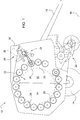
- Fig. 1
- eine schematische Seitenansicht einer Ballenpresse mit einer Umhüllungseinrichtung,
- Fig. 2a
- eine vergrößerte schematische Seitenansicht der Umhüllungseinrichtung aus
Fig. 1 , mit einer Blockiereinrichtung in einer deaktivierten Stellung, - Fig. 2b
- eine vergrößerte schematische Seitenansicht gemäß
Fig. 1 , wobei die Blockiereinrichtung eine aktivierte Stellung einnimmt und - Fig. 3 a und b
- eine vergrößerte schematische Seitenansicht eines Schwenkelements aus
Fig. 2 a und b, zur Verdeutlichung von entsprechenden Wirklinien eines Federelements der Blockiereinrichtung in den jeweiligen Positionen der Blockiereinrichtung. - Eine in der
Figur 1 schematisch dargestellte Ballenpresse 10, in der Art einer landwirtschaftlichen Ballenpresse zur Bildung rundzylindrischer Ballen, umfasst einen ersten Gehäuseteil 12, der sich mittels Rädern 14 auf einem Untergrund 16 abstützt und mittels einer Deichsel 18 an ein nicht gezeigtes Zugfahrzeug, z. B. einen Ackerschlepper, anschließbar ist. - An einer in Vorwärtsfahrtrichtung vorderen unteren Seite des ersten Gehäuseteils 12 befindet sich in bekannter Weise eine Erntegutaufnahmeeinrichtung 20 für Erntegut, wobei der erste Gehäuseteil 12 einen vorderen Teil eines Ballenpressraums 22 umgibt. An dem rückwärtigen oberen Eckbereich des ersten Gehäuseteils 12 befindet sich ein Lager (nicht gezeigt) für einen schwenkbaren zweiten Gehäuseteil 24, der einen hinteren Teil des Ballenpressraums 22 umgibt. Der zweite Gehäuseteil 24 gibt im geöffneten Zustand (nicht gezeigt) einen Auslass (nicht gezeigt) frei, durch welchen ein von der Ballenpresse 10 gepresster Ballen (nicht gezeigt) abgesetzt bzw. entladen oder ausgeworfen werden kann. Der schwenkbare zweite Gehäuseteil 24 kann mittels Stellmotoren (nicht gezeigt) betätigt werden (geöffnet und geschlossen werden) und stellt somit eine Auslassklappe für einen im Ballenpressraum 22 gepressten Ballen dar.
- Die Ballenpresse 10, die gemäß der Darstellung in
Figur 1 mit einem größenunveränderlichem Ballenpressraum 22 ausgebildet ist, enthält eine Vielzahl zueinander parallel verlaufender Presselemente zum Pressen von Erntegut in Form von Presswalzen 26 (exemplarisch wurden hier nur einige wenige Presswalzen 26 mit dem Bezugszeichen "26" versehen), deren Rotationsachsen bei geschlossenem zweiten Gehäuseteil 24 auf einem Kreisbogen gelegen sind, und von denen wenigstens einige angetrieben sind. Alternativ kann die Ballenpresse 10 auch in bekannter Weise als solche mit einem größenveränderlichen Ballenpressraum 22 bzw. als Ballenpresse 10 mit variablem Ballenpressraum 22 ausgebildet werden, wobei die Presselemente dann, ebenfalls in bekannter Weise, als Riemen, Gurte oder Kettenanordnungen (nicht gezeigt) ausgebildet sein können. - Ferner umfasst die Ballenpresse 10 eine Umhüllungseinrichtung 28, die mit einer Hüllmaterialrolle 30 bestückt ist. Als Hüllmaterial 32 kann Netz, Folie oder auch Garn eingesetzt werden. Die Umhüllungseinrichtung 28 umfasst ferner eine Zufuhreinrichtung (nicht gezeigt) für das Hüllmaterial 32, mittels welcher das Hüllmaterial 32 von der Hüllmaterialrolle 32 in den Ballenpressraum 22 geführt wird.
- Nachdem der eigentliche Pressvorgang, also die Erntegutaufnahme und Bildung eines Ballens 10 durch die Presswalzen 26, abgeschlossen ist, wird die Umhüllungseinrichtung 28 aktiviert, und ein sich dem Pressvorgang anschließender Umhüllungsvorgang eingeleitet.
- Bei Einleiten eines Umhüllungsvorgangs wird in einer Hüllmaterialeinführungsphase durch eine mechanisch ausgelöste Zufuhrbewegung Hüllmaterial 32 in Richtung des Ballenpressraums 22 geführt, so dass ein freies Hüllmaterialende mit dem sich in dem Ballenpressraum 22 rotierenden Ballen in Berührung kommen kann und das Hüllmaterial 32 mitgerissen und aufgenommen wird. Durch Rotation des Ballens wird das Hüllmaterial 32 in einer Hüllmaterialwickelphase in einer oder mehreren Lagen um den Umfang des Ballens gewickelt. Der Umhüllungsvorgang wird mit einer Hüllmaterialtrennphase, in der das um den Ballen gewickelte Hüllmaterial 32 von der Hüllmaterialrolle 32 durch eine Trenneinrichtung 34 getrennt wird, abgeschlossen.
- Wie in den
Figuren 2a und2b vergrößert gezeigt, weist die Trenneinrichtung 34 eine Messeranordnung 36 auf, die die Trennung des Hüllmaterials 32 in der Hüllmaterialtrennphase unterstützt, in dem sie das Hüllmaterial 32 in bekannter Art und Weise im Zusammenwirken mit einem nicht dargestellten Gegenhalter schneidet. Hierzu kann die Messeranordnung 36 mit Hilfe eines Antriebs 38, der im vorliegenden Ausführungsbeispiel in der Art einer einen Kolben 40 und einen Zylinder 42 aufweisenden Kolben-Zylinder-Anordnung 44 ausgebildet ist, aus einer in denFiguren 2a und2b gezeigten inaktiven Position in eine nicht gezeigte Trennstellung verbracht werden. Wird der Kolben 40 der Kolben-Zylinderanordnung 44 bezogen auf den Zylinder 42 in diesen eingefahren, so führt die Messeranordnung 36 eine Schwenkbewegung aus. - Wie in den
Figuren 2a undb dargestellt, weist die Umhüllungseinrichtung 28 darüber hinaus eine Blockiereinrichtung 46 auf, die die Trenneinrichtung 34 in ihrer inaktiven Stellung blockieren bzw. festlegen kann. Die Blockiereinrichtung 46 weist gemäß dem vorliegenden Ausführungsbeispiel ein Schwenkelement 48 sowie ein als Zugfeder ausgebildetes Federmittel 50 auf. Das Schwenkelement 48 ist an einem Rahmen 52 der Trenneinrichtung 34 um einen Anlenkpunkt 54 schwenkbar vorgesehen und wird durch das Federmittel 50, das einenends an einem ersten Befestigungspunkt 56 mit dem Rahmen 52 und andernends an einem zweiten Befestigungspunkt 58 an dem Schwenkelement 48 angreift, belastet. InFigur 2a wird das Schwenkelement 48 in einer ersten, deaktivierten Stellung A gezeigt, in der es nicht mit der Trenneinrichtung 34 zusammenwirkt und in der es durch das Federmittel 50 in Anlage mit einem an dem Rahmen 52 vorgesehenen Anschlag 60 gehalten wird. InFigur 2b hingegen nimmt das Schwenkelement 50 eine Stellung B ein, in der es die Trenneineinrichtung 34 bzw. die Messeranordnung 36 in der in den Figuren gezeigten inaktiven Position festlegt, in dem es eine Bewegung des Kolbens 44 mit Bezug auf den Zylinder 44 blockiert. - Es wird nun auch auf die
Figuren 3a und 3b der Zeichnung Bezug genommen, in denen das Schwenkelement 48 vergrößert dargestellt ist und an denen die Wirkungsweise des Federmittels 50 detaillierter beschrieben werden soll. Hierzu wird in den Figuren zur Verdeutlichung nicht das Federmittel 50 selbst sondern eine Wirklinie 62 des Federmittels 50 gezeigt. - In
Figur 3a nimmt das Schwenkelement 48 seine deaktivierte Stellung A ein. Das gemäß dem vorliegenden Ausführungsbeispiel als Zugfeder ausgebildet Federmittel 50 belastet das Schwenkelement 48 nun derart, dass es an dem Anschlag 60 zur Anlage kommt. Der Anlenkpunkt 54 liegt einerseits bzw. gemäß dem vorliegenden Ausführungsbeispiel unterhalb der Wirklinie 62 und weist zu dieser einen ersten Abstand X auf. Das Federelement 50 belastet das Schwenkelement 48 in dieser Stellung gegen den Uhrzeigersinn in Richtung des Anschlags 60. - In der in
Figur 3b gezeigten aktivierten Stellung B ist der Anlenkpunkt 54 nun andererseits bzw. gemäß dem vorliegenden Ausführungsbeispiel oberhalb der Wirklinie 62 angeordnet und weist zu dieser einen dem Abstand X entgegengerichteten Abstand Y auf. Das Federmittel 50 belastet das Schwenkelement 48 in dieser Stellung nun in Richtung einer der Darstellung inFigur 3a entgegengesetzten Richtung im Uhrzeigersinn und zwar derart, dass es den Kolben 40 der Kolben-Zylinderanordnung 44 mit Bezug auf den Zylinder 42 blockiert und die Trenneinrichtung 34 somit in ihrer in derFigur 2a gezeigten inaktiven Position festgelegt ist. - Um das Schwenkelement 48 aus seiner in
Figur 3a gezeigten deaktivierten Stellung A in die in derFigur 3b gezeigte, aktive Stellung B zu bringen, muss das Schwenkelement 48 über einen Totpunkt gelangen in dem sich die Wirklinie 62 durch den Anlenkpunkt 54 erstreckt bzw. der Anlenkpunkt 54 von der Wirklinie 62 nicht beabstandet ist (andeutungsweise durch eine unterbrochene Linie 62a dargestellt). Hierzu muss auf das Federmittel 50 bzw. das Schwenkelement 48 von außen eine Kraft aufgebracht werden. In der gezeigten Ausführungsform kann das Schwenkelement 48 manuell aus der in der inFigur 2a gezeigten Stellung gegen die Wirkung des Federmittels 50 in die inFigur 2b gezeigte Stellung gebracht werden. - Dies geschieht vorzugsweise, indem eine Bedienungsperson an dem Schwenkelement 48 angreift und es gegen die Wirkung es Federmittels 50 aus der einen Stellung (A, B) in die andere Stellung (A, B) überführt, wo es durch die Wirkung des Federmittels 50 sicher gehalten wird. Es ist aber auch denkbar, dass eine Bedienungsperson an dem Schwenkelement 48 indirekt, beispielsweise über eine Hebelanordnung, angreift oder aber ein Antrieb vorgesehen ist, mit dem das Schwenkelement 48 aus der einen in die andere Stellung (A, B) überführt werden kann oder von der es zusätzlich und/oder alternativ zu dem Federmittel 50 in seiner jeweiligen Stellung (A, B) gehalten werden kann.
Claims (10)
- Umhüllungseinrichtung (28) zur Umhüllung eines Ballens mit einem Hüllmaterial (32) für eine Ballenpresse (10), insbesondere eine landwirtschaftliche Ballenpresse zur Bildung vorzugsweise rundzylindrischer Ballen, mit einer insbesondere eine Messeranordnung (36) aufweisenden, zwischen wenigstens einer Hüllmitteltrennposition und einer inaktiven Position bewegbaren Trenneinrichtung (34), dadurch gekennzeichnet, dass wenigstens eine Blockiereinrichtung (46) vorgesehen ist, die geeignet ist, die Trenneinrichtung (34), vorzugsweise mechanisch, daran zu hindern, die Hüllmitteltrennposition einzunehmen.
- Umhüllungseinrichtung nach Anspruch 1, dadurch gekennzeichnet, dass die Blockiereinrichtung(46) die Trenneinrichtung (34) zumindest im Wesentlichen in der inaktiven Position festlegen bzw. blockieren kann.
- Umhüllungseinrichtung nach Anspruch 1 oder 2, dadurch gekennzeichnet, dass die Trenneinrichtung (34) einen Antrieb (38), vorzugsweise in der Art einer Kolben-Zylinder-Anordnung (44), aufweist bzw. mit einem solchen zusammenwirkt, wobei die Blockiereinrichtung (46) vorzugsweise geeignet ist, den Antrieb (38), insbesondere den Kolben (40) und/oder den Zylinder (42) der Kolben-Zylinderanordnung (44), in wenigstens einer, vorzugsweise einer zumindest im Wesentlichen eingefahrenen oder ausgefahrenen, Stellung festzulegen bzw. zu blockieren.
- Umhüllungseinrichtung nach einem der vorherigen Ansprüche, dadurch gekennzeichnet, dass die Blockiereinrichtung (46) wenigstens ein Schwenkelement (48) aufweist, welches vorzugsweise einenends um einen Anlenkpunkt (54) schwenkbar an einem Rahmen (52) der Trenneinrichtung (34) angebracht und vorzugsweise andernends ausgebildet ist, um mit der Trenneinrichtung (34) bzw. der Messeranordnung (36) und insbesondere mit dem Antrieb (38) zusammenzuwirken.
- Umhüllungseinrichtung nach Anspruch 4, dadurch gekennzeichnet, dass das Schwenkelement (48) derart ausgebildet ist, dass es in den Kolben (40) eingreifen bzw. diesen umgreifen kann.
- Umhüllungseinrichtung nach einem der vorherigen Ansprüche, dadurch gekennzeichnet, dass wenigstens ein Federmittel (50), insbesondere ausgebildet in der Art einer Zugfeder, vorgesehen ist, das die Blockiereinrichtung (46) bzw. das Schwenkelement (48) in Richtung einer deaktivierten Stellung (A), in der die Blockiereinrichtung (46) bzw. das Schwenkelement (48) nicht mit der Trenneinrichtung (34) zusammenwirkt, und/oder einer aktiven Stellung (B), in der die Blockiereinrichtung (46) bzw. das Schwenkelement (48) die Trenneinrichtung (34) daran hindert, die Hüllmitteltrennposition einzunehmen, belastet bzw. vorspannt.
- Umhüllungseinrichtung nach Anspruch 6, dadurch gekennzeichnet, dass das Federmittel (50) an dem Schwenkelement (48) an einem außerhalb des Anlenkpunkts (54) gelegenen Befestigungspunkt (56) angreift, vorzugsweise derart, dass der Anlenkpunkt (54) in der aktiven Stellung (B) einerseits einer Wirklinie (62) des Federmittels (50) und in der deaktiverten Stellung (A) andererseits der Wirklinie (62) angeordnet ist.
- Blockiereinrichtung (46) geeignet eine Trenneinrichtung (34) einer Umhüllungseinrichtung (28) nach einem oder mehreren der vorherigen Ansprüche daran zu hindern, eine Hüllmitteltrennposition einzunehmen.
- Ballenpresse (10), insbesondere eine landwirtschaftliche Ballenpresse zur Bildung rundzylindrischer Ballen, mit einer Umhüllungseinrichtung (28) nach einem der Ansprüche 1 bis 7.
- Verfahren zur Anpassung einer Ballenpresse (10) nach Anspruch 9 an ein Hüllmaterial (32), dadurch gekennzeichnet, dass die Blockiereinrichtung (36) durch eine Bedienungsperson insbesondere manuell und vorzugsweise gegen eine Belastung durch ein Federmittel (50) aus einer deaktivierten Stellung (A) in eine aktive Stellung (B) bzw. aus einer aktiven (B) in eine deaktivierte Stellung (A) überführt wird.
Applications Claiming Priority (1)
| Application Number | Priority Date | Filing Date | Title |
|---|---|---|---|
| DE102017210813.4A DE102017210813A1 (de) | 2017-06-27 | 2017-06-27 | Umhüllungseinrichtung, Blockiereinrichtung, Ballenpresse und Verfahren zur Anpassung einer Ballenpresse an ein Hüllmaterial |
Publications (2)
| Publication Number | Publication Date |
|---|---|
| EP3420805A1 true EP3420805A1 (de) | 2019-01-02 |
| EP3420805B1 EP3420805B1 (de) | 2022-01-19 |
Family
ID=62110968
Family Applications (1)
| Application Number | Title | Priority Date | Filing Date |
|---|---|---|---|
| EP18170522.9A Active EP3420805B1 (de) | 2017-06-27 | 2018-05-03 | Umhüllungseinrichtung, blockiereinrichtung, ballenpresse und verfahren zur anpassung einer ballenpresse an ein hüllmaterial |
Country Status (4)
| Country | Link |
|---|---|
| US (1) | US11234374B2 (de) |
| EP (1) | EP3420805B1 (de) |
| CN (1) | CN109121746B (de) |
| DE (1) | DE102017210813A1 (de) |
Citations (4)
| Publication number | Priority date | Publication date | Assignee | Title |
|---|---|---|---|---|
| DE3330757A1 (de) * | 1983-07-28 | 1985-02-07 | Claas Ohg, 4834 Harsewinkel | Grossballenpresse fuer landwirtschaftliches erntegut |
| DE3617155A1 (de) * | 1986-05-22 | 1987-11-26 | Zweegers & Zonen P J | Rundballenpresse |
| DE102005055375A1 (de) * | 2005-11-17 | 2007-05-31 | Usines Claas France S.A.S., St. Rémy-Woippy | Rundballenpresse |
| DE102009010547B3 (de) * | 2009-02-25 | 2010-06-24 | Siegfried Unseld | Schneideinrichtung für Wickelmaterialbahnen |
Family Cites Families (20)
| Publication number | Priority date | Publication date | Assignee | Title |
|---|---|---|---|---|
| US2468641A (en) * | 1944-03-03 | 1949-04-26 | Allis Chalmers Mfg Co | Rotary baler |
| US3781988A (en) * | 1972-08-29 | 1974-01-01 | R Jones | Safety paper carton opening blade holder |
| US4563854A (en) * | 1983-07-28 | 1986-01-14 | Claas Ohg | Round baler for forming bales of agricultural products |
| US4768431A (en) * | 1987-05-01 | 1988-09-06 | Ford New Holland, Inc. | Net dispenser drive for round balers |
| US4802395A (en) * | 1987-05-01 | 1989-02-07 | Ford New Holland, Inc. | Knife assembly for net dispensing apparatus |
| US5231828A (en) * | 1992-02-26 | 1993-08-03 | M & W Gear Company | Wrapping mechanism for round balers |
| DE4426034A1 (de) * | 1994-07-22 | 1996-01-25 | Deere & Co | Ballenpresse |
| US5816038A (en) * | 1996-10-18 | 1998-10-06 | Hay & Forage Industries | End of round bale twine guides |
| DE19707662A1 (de) * | 1997-02-26 | 1998-08-27 | Claas Saulgau Gmbh | Schneidwerk für landwirtschaftliche Maschinen |
| US6116010A (en) * | 1999-05-28 | 2000-09-12 | Deere & Company | Knife guard for a cutterbar assembly |
| GB2425526A (en) * | 2005-04-27 | 2006-11-01 | Cnh Belgium Nv | Bale wrapping apparatus |
| GB2451826A (en) * | 2007-08-14 | 2009-02-18 | Cnh Belgium Nv | Square Baler for forming sliced bales |
| US7918072B2 (en) * | 2008-10-10 | 2011-04-05 | Cnh America Llc | Mechanical net wrapper |
| US7784400B2 (en) * | 2008-12-30 | 2010-08-31 | Cnh America Llc | Duckbill cam geometry for reduced actuation forces |
| NL1037002C2 (nl) * | 2009-05-29 | 2010-11-30 | Lely Patent Nv | Centreren van folie. |
| CN101953259B (zh) * | 2010-08-05 | 2012-06-27 | 中国农业大学 | 分体式打结器 |
| GB201315396D0 (en) * | 2013-08-29 | 2013-10-16 | Kuhn Geldrop Bv | Baler and method of baling |
| DE102014215729A1 (de) * | 2014-08-08 | 2016-02-11 | Deere & Company | Ballenwickeleinrichtung |
| CN106134651B (zh) * | 2016-06-29 | 2018-04-13 | 安徽盛昌生物能源科技开发有限公司 | 一种避震捆草机 |
| EP3626413B1 (de) * | 2017-06-07 | 2021-07-21 | Stanley Black & Decker, Inc. | Messer |
-
2017
- 2017-06-27 DE DE102017210813.4A patent/DE102017210813A1/de not_active Withdrawn
-
2018
- 2018-05-03 EP EP18170522.9A patent/EP3420805B1/de active Active
- 2018-05-24 CN CN201810508020.8A patent/CN109121746B/zh active Active
- 2018-06-19 US US16/011,680 patent/US11234374B2/en active Active
Patent Citations (4)
| Publication number | Priority date | Publication date | Assignee | Title |
|---|---|---|---|---|
| DE3330757A1 (de) * | 1983-07-28 | 1985-02-07 | Claas Ohg, 4834 Harsewinkel | Grossballenpresse fuer landwirtschaftliches erntegut |
| DE3617155A1 (de) * | 1986-05-22 | 1987-11-26 | Zweegers & Zonen P J | Rundballenpresse |
| DE102005055375A1 (de) * | 2005-11-17 | 2007-05-31 | Usines Claas France S.A.S., St. Rémy-Woippy | Rundballenpresse |
| DE102009010547B3 (de) * | 2009-02-25 | 2010-06-24 | Siegfried Unseld | Schneideinrichtung für Wickelmaterialbahnen |
Also Published As
| Publication number | Publication date |
|---|---|
| US11234374B2 (en) | 2022-02-01 |
| CN109121746B (zh) | 2022-07-01 |
| EP3420805B1 (de) | 2022-01-19 |
| CN109121746A (zh) | 2019-01-04 |
| US20180368327A1 (en) | 2018-12-27 |
| DE102017210813A1 (de) | 2018-12-27 |
Similar Documents
| Publication | Publication Date | Title |
|---|---|---|
| DE19701421A1 (de) | Rundballenpresse für landwirtschaftliche Halmgüter | |
| EP2984922B1 (de) | Ballenwickeleinrichtung | |
| EP2939523B1 (de) | Ballenwickeleinrichtung und rundballenpresse mit einer solchen | |
| EP1917849A1 (de) | Umhüllungsvorrichtung | |
| DE102016215085A1 (de) | Ballenwickeleinrichtung für eine Rundballenpresse, Rundballenpresse und Verfahren zum Betreiben einer solchen | |
| EP3854201A1 (de) | Wiegeeinrichtung und erntebergungsgerät | |
| EP3222134A1 (de) | Abstreifereinrichtung, presse und verfahren | |
| EP1344448B1 (de) | Rundballenpresse | |
| DE10255175A1 (de) | Ballenpresse | |
| EP0499064B1 (de) | Maschine zum Aufnehmen und Pressen von landwirtschaftlichem Erntegut | |
| EP1813145B1 (de) | Vorrichtung zum Umhüllen eines Ballens mit einer Hüllbahn und Ballenpresse | |
| EP3421387B1 (de) | Hüllmaterial für eine ballenpresse | |
| EP3482625B1 (de) | Leiteinrichtung und ballenpresse | |
| EP3501261B1 (de) | Leitmittel, ballenpresse und verfahren | |
| EP3569056B1 (de) | Pressmittelleiteinrichtung und presse | |
| EP3028561B1 (de) | Festkammerpresse | |
| EP1446998A1 (de) | Vorrichtung zum Unterstützen des Austritts eines Rundballens | |
| EP0564922A1 (de) | Schneidwerk | |
| EP3414991B1 (de) | Umhüllungseinrichtung und rundballenpresse | |
| EP3420805B1 (de) | Umhüllungseinrichtung, blockiereinrichtung, ballenpresse und verfahren zur anpassung einer ballenpresse an ein hüllmaterial | |
| EP0193568B1 (de) | Fahrbare grossballenpresse für landwirtschaftliches erntegut | |
| DE10153517A1 (de) | Bindevorrichtung für eine Rundballenpresse | |
| DD236246A5 (de) | Rundballenpresse | |
| EP3130216A1 (de) | Ballenpresse und leiteinrichtung | |
| EP3760031B1 (de) | Rundballenpresse und verfahren zum betrieb einer rundballenpresse |
Legal Events
| Date | Code | Title | Description |
|---|---|---|---|
| PUAI | Public reference made under article 153(3) epc to a published international application that has entered the european phase |
Free format text: ORIGINAL CODE: 0009012 |
|
| STAA | Information on the status of an ep patent application or granted ep patent |
Free format text: STATUS: THE APPLICATION HAS BEEN PUBLISHED |
|
| AK | Designated contracting states |
Kind code of ref document: A1 Designated state(s): AL AT BE BG CH CY CZ DE DK EE ES FI FR GB GR HR HU IE IS IT LI LT LU LV MC MK MT NL NO PL PT RO RS SE SI SK SM TR |
|
| AX | Request for extension of the european patent |
Extension state: BA ME |
|
| STAA | Information on the status of an ep patent application or granted ep patent |
Free format text: STATUS: REQUEST FOR EXAMINATION WAS MADE |
|
| 17P | Request for examination filed |
Effective date: 20190702 |
|
| RBV | Designated contracting states (corrected) |
Designated state(s): AL AT BE BG CH CY CZ DE DK EE ES FI FR GB GR HR HU IE IS IT LI LT LU LV MC MK MT NL NO PL PT RO RS SE SI SK SM TR |
|
| GRAP | Despatch of communication of intention to grant a patent |
Free format text: ORIGINAL CODE: EPIDOSNIGR1 |
|
| STAA | Information on the status of an ep patent application or granted ep patent |
Free format text: STATUS: GRANT OF PATENT IS INTENDED |
|
| INTG | Intention to grant announced |
Effective date: 20210907 |
|
| RIN1 | Information on inventor provided before grant (corrected) |
Inventor name: PERROTIN, FREDERIC Inventor name: GRESSET, PASCAL |
|
| GRAS | Grant fee paid |
Free format text: ORIGINAL CODE: EPIDOSNIGR3 |
|
| GRAA | (expected) grant |
Free format text: ORIGINAL CODE: 0009210 |
|
| STAA | Information on the status of an ep patent application or granted ep patent |
Free format text: STATUS: THE PATENT HAS BEEN GRANTED |
|
| AK | Designated contracting states |
Kind code of ref document: B1 Designated state(s): AL AT BE BG CH CY CZ DE DK EE ES FI FR GB GR HR HU IE IS IT LI LT LU LV MC MK MT NL NO PL PT RO RS SE SI SK SM TR |
|
| REG | Reference to a national code |
Ref country code: GB Ref legal event code: FG4D Free format text: NOT ENGLISH |
|
| REG | Reference to a national code |
Ref country code: CH Ref legal event code: EP |
|
| REG | Reference to a national code |
Ref country code: DE Ref legal event code: R096 Ref document number: 502018008553 Country of ref document: DE |
|
| REG | Reference to a national code |
Ref country code: AT Ref legal event code: REF Ref document number: 1463241 Country of ref document: AT Kind code of ref document: T Effective date: 20220215 |
|
| REG | Reference to a national code |
Ref country code: IE Ref legal event code: FG4D Free format text: LANGUAGE OF EP DOCUMENT: GERMAN |
|
| REG | Reference to a national code |
Ref country code: LT Ref legal event code: MG9D |
|
| REG | Reference to a national code |
Ref country code: NL Ref legal event code: MP Effective date: 20220119 |
|
| PG25 | Lapsed in a contracting state [announced via postgrant information from national office to epo] |
Ref country code: NL Free format text: LAPSE BECAUSE OF FAILURE TO SUBMIT A TRANSLATION OF THE DESCRIPTION OR TO PAY THE FEE WITHIN THE PRESCRIBED TIME-LIMIT Effective date: 20220119 |
|
| PG25 | Lapsed in a contracting state [announced via postgrant information from national office to epo] |
Ref country code: SE Free format text: LAPSE BECAUSE OF FAILURE TO SUBMIT A TRANSLATION OF THE DESCRIPTION OR TO PAY THE FEE WITHIN THE PRESCRIBED TIME-LIMIT Effective date: 20220119 Ref country code: RS Free format text: LAPSE BECAUSE OF FAILURE TO SUBMIT A TRANSLATION OF THE DESCRIPTION OR TO PAY THE FEE WITHIN THE PRESCRIBED TIME-LIMIT Effective date: 20220119 Ref country code: PT Free format text: LAPSE BECAUSE OF FAILURE TO SUBMIT A TRANSLATION OF THE DESCRIPTION OR TO PAY THE FEE WITHIN THE PRESCRIBED TIME-LIMIT Effective date: 20220519 Ref country code: NO Free format text: LAPSE BECAUSE OF FAILURE TO SUBMIT A TRANSLATION OF THE DESCRIPTION OR TO PAY THE FEE WITHIN THE PRESCRIBED TIME-LIMIT Effective date: 20220419 Ref country code: LT Free format text: LAPSE BECAUSE OF FAILURE TO SUBMIT A TRANSLATION OF THE DESCRIPTION OR TO PAY THE FEE WITHIN THE PRESCRIBED TIME-LIMIT Effective date: 20220119 Ref country code: HR Free format text: LAPSE BECAUSE OF FAILURE TO SUBMIT A TRANSLATION OF THE DESCRIPTION OR TO PAY THE FEE WITHIN THE PRESCRIBED TIME-LIMIT Effective date: 20220119 Ref country code: ES Free format text: LAPSE BECAUSE OF FAILURE TO SUBMIT A TRANSLATION OF THE DESCRIPTION OR TO PAY THE FEE WITHIN THE PRESCRIBED TIME-LIMIT Effective date: 20220119 Ref country code: BG Free format text: LAPSE BECAUSE OF FAILURE TO SUBMIT A TRANSLATION OF THE DESCRIPTION OR TO PAY THE FEE WITHIN THE PRESCRIBED TIME-LIMIT Effective date: 20220419 |
|
| PG25 | Lapsed in a contracting state [announced via postgrant information from national office to epo] |
Ref country code: PL Free format text: LAPSE BECAUSE OF FAILURE TO SUBMIT A TRANSLATION OF THE DESCRIPTION OR TO PAY THE FEE WITHIN THE PRESCRIBED TIME-LIMIT Effective date: 20220119 Ref country code: LV Free format text: LAPSE BECAUSE OF FAILURE TO SUBMIT A TRANSLATION OF THE DESCRIPTION OR TO PAY THE FEE WITHIN THE PRESCRIBED TIME-LIMIT Effective date: 20220119 Ref country code: GR Free format text: LAPSE BECAUSE OF FAILURE TO SUBMIT A TRANSLATION OF THE DESCRIPTION OR TO PAY THE FEE WITHIN THE PRESCRIBED TIME-LIMIT Effective date: 20220420 Ref country code: FI Free format text: LAPSE BECAUSE OF FAILURE TO SUBMIT A TRANSLATION OF THE DESCRIPTION OR TO PAY THE FEE WITHIN THE PRESCRIBED TIME-LIMIT Effective date: 20220119 |
|
| PG25 | Lapsed in a contracting state [announced via postgrant information from national office to epo] |
Ref country code: IS Free format text: LAPSE BECAUSE OF FAILURE TO SUBMIT A TRANSLATION OF THE DESCRIPTION OR TO PAY THE FEE WITHIN THE PRESCRIBED TIME-LIMIT Effective date: 20220519 |
|
| REG | Reference to a national code |
Ref country code: DE Ref legal event code: R097 Ref document number: 502018008553 Country of ref document: DE |
|
| PG25 | Lapsed in a contracting state [announced via postgrant information from national office to epo] |
Ref country code: SM Free format text: LAPSE BECAUSE OF FAILURE TO SUBMIT A TRANSLATION OF THE DESCRIPTION OR TO PAY THE FEE WITHIN THE PRESCRIBED TIME-LIMIT Effective date: 20220119 Ref country code: SK Free format text: LAPSE BECAUSE OF FAILURE TO SUBMIT A TRANSLATION OF THE DESCRIPTION OR TO PAY THE FEE WITHIN THE PRESCRIBED TIME-LIMIT Effective date: 20220119 Ref country code: RO Free format text: LAPSE BECAUSE OF FAILURE TO SUBMIT A TRANSLATION OF THE DESCRIPTION OR TO PAY THE FEE WITHIN THE PRESCRIBED TIME-LIMIT Effective date: 20220119 Ref country code: EE Free format text: LAPSE BECAUSE OF FAILURE TO SUBMIT A TRANSLATION OF THE DESCRIPTION OR TO PAY THE FEE WITHIN THE PRESCRIBED TIME-LIMIT Effective date: 20220119 Ref country code: DK Free format text: LAPSE BECAUSE OF FAILURE TO SUBMIT A TRANSLATION OF THE DESCRIPTION OR TO PAY THE FEE WITHIN THE PRESCRIBED TIME-LIMIT Effective date: 20220119 Ref country code: CZ Free format text: LAPSE BECAUSE OF FAILURE TO SUBMIT A TRANSLATION OF THE DESCRIPTION OR TO PAY THE FEE WITHIN THE PRESCRIBED TIME-LIMIT Effective date: 20220119 |
|
| PLBE | No opposition filed within time limit |
Free format text: ORIGINAL CODE: 0009261 |
|
| STAA | Information on the status of an ep patent application or granted ep patent |
Free format text: STATUS: NO OPPOSITION FILED WITHIN TIME LIMIT |
|
| PG25 | Lapsed in a contracting state [announced via postgrant information from national office to epo] |
Ref country code: AL Free format text: LAPSE BECAUSE OF FAILURE TO SUBMIT A TRANSLATION OF THE DESCRIPTION OR TO PAY THE FEE WITHIN THE PRESCRIBED TIME-LIMIT Effective date: 20220119 |
|
| 26N | No opposition filed |
Effective date: 20221020 |
|
| REG | Reference to a national code |
Ref country code: CH Ref legal event code: PL |
|
| REG | Reference to a national code |
Ref country code: BE Ref legal event code: MM Effective date: 20220531 |
|
| GBPC | Gb: european patent ceased through non-payment of renewal fee |
Effective date: 20220503 |
|
| PG25 | Lapsed in a contracting state [announced via postgrant information from national office to epo] |
Ref country code: MC Free format text: LAPSE BECAUSE OF FAILURE TO SUBMIT A TRANSLATION OF THE DESCRIPTION OR TO PAY THE FEE WITHIN THE PRESCRIBED TIME-LIMIT Effective date: 20220119 Ref country code: LU Free format text: LAPSE BECAUSE OF NON-PAYMENT OF DUE FEES Effective date: 20220503 Ref country code: LI Free format text: LAPSE BECAUSE OF NON-PAYMENT OF DUE FEES Effective date: 20220531 Ref country code: CH Free format text: LAPSE BECAUSE OF NON-PAYMENT OF DUE FEES Effective date: 20220531 |
|
| PG25 | Lapsed in a contracting state [announced via postgrant information from national office to epo] |
Ref country code: SI Free format text: LAPSE BECAUSE OF FAILURE TO SUBMIT A TRANSLATION OF THE DESCRIPTION OR TO PAY THE FEE WITHIN THE PRESCRIBED TIME-LIMIT Effective date: 20220119 |
|
| PG25 | Lapsed in a contracting state [announced via postgrant information from national office to epo] |
Ref country code: IE Free format text: LAPSE BECAUSE OF NON-PAYMENT OF DUE FEES Effective date: 20220503 |
|
| PG25 | Lapsed in a contracting state [announced via postgrant information from national office to epo] |
Ref country code: GB Free format text: LAPSE BECAUSE OF NON-PAYMENT OF DUE FEES Effective date: 20220503 Ref country code: BE Free format text: LAPSE BECAUSE OF NON-PAYMENT OF DUE FEES Effective date: 20220531 |
|
| PG25 | Lapsed in a contracting state [announced via postgrant information from national office to epo] |
Ref country code: IT Free format text: LAPSE BECAUSE OF FAILURE TO SUBMIT A TRANSLATION OF THE DESCRIPTION OR TO PAY THE FEE WITHIN THE PRESCRIBED TIME-LIMIT Effective date: 20220119 |
|
| PG25 | Lapsed in a contracting state [announced via postgrant information from national office to epo] |
Ref country code: HU Free format text: LAPSE BECAUSE OF FAILURE TO SUBMIT A TRANSLATION OF THE DESCRIPTION OR TO PAY THE FEE WITHIN THE PRESCRIBED TIME-LIMIT; INVALID AB INITIO Effective date: 20180503 |
|
| PG25 | Lapsed in a contracting state [announced via postgrant information from national office to epo] |
Ref country code: MK Free format text: LAPSE BECAUSE OF FAILURE TO SUBMIT A TRANSLATION OF THE DESCRIPTION OR TO PAY THE FEE WITHIN THE PRESCRIBED TIME-LIMIT Effective date: 20220119 Ref country code: CY Free format text: LAPSE BECAUSE OF FAILURE TO SUBMIT A TRANSLATION OF THE DESCRIPTION OR TO PAY THE FEE WITHIN THE PRESCRIBED TIME-LIMIT Effective date: 20220119 |
|
| PGFP | Annual fee paid to national office [announced via postgrant information from national office to epo] |
Ref country code: DE Payment date: 20240419 Year of fee payment: 7 |
|
| REG | Reference to a national code |
Ref country code: AT Ref legal event code: MM01 Ref document number: 1463241 Country of ref document: AT Kind code of ref document: T Effective date: 20230503 |
|
| PG25 | Lapsed in a contracting state [announced via postgrant information from national office to epo] |
Ref country code: AT Free format text: LAPSE BECAUSE OF NON-PAYMENT OF DUE FEES Effective date: 20230503 |
|
| PG25 | Lapsed in a contracting state [announced via postgrant information from national office to epo] |
Ref country code: AT Free format text: LAPSE BECAUSE OF NON-PAYMENT OF DUE FEES Effective date: 20230503 |
|
| PG25 | Lapsed in a contracting state [announced via postgrant information from national office to epo] |
Ref country code: MT Free format text: LAPSE BECAUSE OF FAILURE TO SUBMIT A TRANSLATION OF THE DESCRIPTION OR TO PAY THE FEE WITHIN THE PRESCRIBED TIME-LIMIT Effective date: 20220119 |
|
| PGFP | Annual fee paid to national office [announced via postgrant information from national office to epo] |
Ref country code: FR Payment date: 20250526 Year of fee payment: 8 |
|
| REG | Reference to a national code |
Ref country code: DE Ref legal event code: R119 Ref document number: 502018008553 Country of ref document: DE |
|
| PG25 | Lapsed in a contracting state [announced via postgrant information from national office to epo] |
Ref country code: TR Free format text: LAPSE BECAUSE OF FAILURE TO SUBMIT A TRANSLATION OF THE DESCRIPTION OR TO PAY THE FEE WITHIN THE PRESCRIBED TIME-LIMIT Effective date: 20220119 |
|
| PG25 | Lapsed in a contracting state [announced via postgrant information from national office to epo] |
Ref country code: DE Free format text: LAPSE BECAUSE OF NON-PAYMENT OF DUE FEES Effective date: 20251202 |
|
| PGFP | Annual fee paid to national office [announced via postgrant information from national office to epo] |
Ref country code: AT Payment date: 20260410 Year of fee payment: 5 |