EP3420622B1 - Electronic device configuration - Google Patents
Electronic device configuration Download PDFInfo
- Publication number
- EP3420622B1 EP3420622B1 EP17707092.7A EP17707092A EP3420622B1 EP 3420622 B1 EP3420622 B1 EP 3420622B1 EP 17707092 A EP17707092 A EP 17707092A EP 3420622 B1 EP3420622 B1 EP 3420622B1
- Authority
- EP
- European Patent Office
- Prior art keywords
- isolator
- isolator device
- configuration
- functionality
- wireless
- Prior art date
- Legal status (The legal status is an assumption and is not a legal conclusion. Google has not performed a legal analysis and makes no representation as to the accuracy of the status listed.)
- Active
Links
Images


Classifications
-
- H—ELECTRICITY
- H01—ELECTRIC ELEMENTS
- H01R—ELECTRICALLY-CONDUCTIVE CONNECTIONS; STRUCTURAL ASSOCIATIONS OF A PLURALITY OF MUTUALLY-INSULATED ELECTRICAL CONNECTING ELEMENTS; COUPLING DEVICES; CURRENT COLLECTORS
- H01R13/00—Details of coupling devices of the kinds covered by groups H01R12/70 or H01R24/00 - H01R33/00
-
- H—ELECTRICITY
- H02—GENERATION; CONVERSION OR DISTRIBUTION OF ELECTRIC POWER
- H02H—EMERGENCY PROTECTIVE CIRCUIT ARRANGEMENTS
- H02H9/00—Emergency protective circuit arrangements for limiting excess current or voltage without disconnection
- H02H9/008—Intrinsically safe circuits
-
- G—PHYSICS
- G06—COMPUTING OR CALCULATING; COUNTING
- G06F—ELECTRIC DIGITAL DATA PROCESSING
- G06F9/00—Arrangements for program control, e.g. control units
- G06F9/06—Arrangements for program control, e.g. control units using stored programs, i.e. using an internal store of processing equipment to receive or retain programs
- G06F9/44—Arrangements for executing specific programs
- G06F9/445—Program loading or initiating
- G06F9/44505—Configuring for program initiating, e.g. using registry, configuration files
-
- H—ELECTRICITY
- H02—GENERATION; CONVERSION OR DISTRIBUTION OF ELECTRIC POWER
- H02H—EMERGENCY PROTECTIVE CIRCUIT ARRANGEMENTS
- H02H1/00—Details of emergency protective circuit arrangements
- H02H1/0061—Details of emergency protective circuit arrangements concerning transmission of signals
-
- H—ELECTRICITY
- H02—GENERATION; CONVERSION OR DISTRIBUTION OF ELECTRIC POWER
- H02H—EMERGENCY PROTECTIVE CIRCUIT ARRANGEMENTS
- H02H3/00—Emergency protective circuit arrangements for automatic disconnection directly responsive to an undesired change from normal electric working condition with or without subsequent reconnection ; integrated protection
- H02H3/006—Calibration or setting of parameters
-
- H—ELECTRICITY
- H02—GENERATION; CONVERSION OR DISTRIBUTION OF ELECTRIC POWER
- H02H—EMERGENCY PROTECTIVE CIRCUIT ARRANGEMENTS
- H02H9/00—Emergency protective circuit arrangements for limiting excess current or voltage without disconnection
-
- H—ELECTRICITY
- H04—ELECTRIC COMMUNICATION TECHNIQUE
- H04B—TRANSMISSION
- H04B5/00—Near-field transmission systems, e.g. inductive or capacitive transmission systems
- H04B5/70—Near-field transmission systems, e.g. inductive or capacitive transmission systems specially adapted for specific purposes
- H04B5/77—Near-field transmission systems, e.g. inductive or capacitive transmission systems specially adapted for specific purposes for interrogation
-
- H—ELECTRICITY
- H04—ELECTRIC COMMUNICATION TECHNIQUE
- H04B—TRANSMISSION
- H04B5/00—Near-field transmission systems, e.g. inductive or capacitive transmission systems
- H04B5/20—Near-field transmission systems, e.g. inductive or capacitive transmission systems characterised by the transmission technique; characterised by the transmission medium
-
- H—ELECTRICITY
- H04—ELECTRIC COMMUNICATION TECHNIQUE
- H04W—WIRELESS COMMUNICATION NETWORKS
- H04W4/00—Services specially adapted for wireless communication networks; Facilities therefor
- H04W4/80—Services using short range communication, e.g. near-field communication [NFC], radio-frequency identification [RFID] or low energy communication
Definitions
- the present disclosure relates to the configuration of a functional electronic device such as, for example, an electronic device offering isolation and/or barrier functionality and can, if required, relate to devices operating in intrinsically safe environments.
- a configuration unit is connected to the device either by way of serial lines, or by way of a plug-in device, both of which requiring physical connection to the already assembled device. It is commonly required that switches are employed for achieving the selection of the required reconfiguration.
- EMC Electromagnetic Compatibility
- US 2016/165702 discloses a programmable lighting device having a power supply circuit including a galvanic separation element, and the present invention seeks to provide for a functional electronic device, having configurable functionality and offering one or more advantages over known such devices.
- US 2015/099464 A1 discloses a switching device and a method of controlling a switching device.
- the switching device comprises a switching module configured to perform switching for an electric circuit; a processor module configured to control the switching module; and a communication module coupled to the processor module, the communication module configured to effect communication between the processor module and an external device, wherein the communication module is configured to communicate with the external device using a near field communication signal.
- US 2007/247768 A1 discloses a system comprising an electronic circuit breaker including an RFID component having an RFID module for storing data and a microcontroller connected to the RFID module and controlling the operation of the breaker in accordance with the data; and a handheld device for communicating with the electronic circuit breaker, the handheld device including a microcontroller controlling the operation of the handheld device and a communicating component connected to the microcontroller communicating wirelessly with the electronic circuit breaker.
- an isolator device for providing circuit isolation and arranged to offer configurable functionality for alteration of the configuration of the isolator device, the isolator device including a universal isolator comprising an isolation functionality and a barrier functionality; wireless reception means for receiving wireless configuration data for selective configuration of the isolator device; and means for wireless transmission of data relating to the configuration state of the isolator device; wherein the isolator device is arranged to transmit device status and diagnostic information; and wherein the isolator device comprises a light emitting diode, LED, arranged to indicate a selection of the isolator device for wireless configuration.
- the invention provides for a far more flexible, efficient, reliable and also potentially cost-effective configuration of the functional device.
- the functional device of the present invention allows an operative to configure the device remotely, and from an appropriate distance, and in any appropriate situation such as, for example, but not limited to, while the device is in a powered, or an unpowered, state, while the device is in assembly mode or indeed in the post-assembly test mode, while the device is either mounted within a functional system, or being manually handled for mounting in such a system, and also while located in situ for example in the field.
- the electronic isolator device includes means for wireless transmission of data relating to its configured state.
- any previous configuration of the device can readily be remotely checked, and re-checked as required, and at any appropriate time during testing, or when mounted in the field for use.
- the wireless reception means is arranged for receiving wireless configuration data while the device is powered.
- the wireless reception means is arranged for receiving wireless configuration data while the device is not in a powered state.
- the device includes a non-volatile memory functionality.
- the wireless reception means comprises a RFID device.
- the functional electronic device can include near field communication functionality.
- the wireless reception means can exhibit near field communication functionality.
- the electronic functional device can be arranged to be mobile-enabled.
- the electronic functional device comprises an isolator device.
- isolator device comprises an universal isolator.
- the electronic functional device comprises a barrier device.
- the functional electronic device is arranged for offering safety functionality for devices operating within an intrinsically safe environment.
- the present invention provides for particularly efficient, adaptable and cost-effective means for achieving, maintaining, and readily checking, in an advantageously remote manner, the configuration of a functional device such as a universal isolator.
- the configuration can be achieved, maintained, checked and whether during assembly, post-assembly, during commissioning or later in field-test and in-situ use scenarios.
- the invention is be arranged such that data obtained from the device comprises device status and diagnostic information.
- any communication devices such as smartphones increasingly have the facility of conversing with an RFID chip via an appropriate application. Accordingly, the configuration unit can then advantageously be incorporated into known and commonly available communication devices such as smart phone devices, laptop computers and tablet devices.
- the cost and footprint of RFID devices is also advantageously less than external EEPROMs such as are currently employed for universal isolator configuration. Additionally there is no need for expensive connectors and associated components.
- a device can therefore advantageously, inspect, and check the configuration at any time when in the vicinity of the functional device.
- multiple devices can be readily configured/checked as and when required through simultaneous receipt of a configuring/interrogating transmission from a configuration unit.
- Fig. 1A there is provided a schematic illustration of a universal isolator which can be arranged, for example, to offer isolation to field devices arranged to operate within an intrinsically safe environment.
- the isolator comprises a microprocessor based control element 111 in communication with a non-volatile storage element 112 as indicated by the opposing arrows.
- the combination of the microprocessor based control element 111 and the non-volatile storage 112 provides for an appropriate one of a plurality of possible configurations for the isolator device as required by the manner of isolation, for example whether within the digital domain or analog domain, and the nature of the field devices, to be isolated.
- the particular configuration of the isolator 101 to be employed is controlled through use of a configuration unit which connects to the microprocessor base control element by way of for example, a plug-in connector 121, or a serial connector 122.
- the plug-in connector 121 is arranged to be received in a socket 131, whereas the connector 122 is arranged to be received in a connector slot 132 as illustrated.
- FIG. 1B Further detail of the use of such a known configurable universal isolator 101 is illustrated with reference to Fig. 1B .
- a plurality of seven isolator units 101-107 are illustrated and wherein one 135 of the sockets is arranged to receive the plug 121 associated with a configuration unit for the delivery of configuration data to the configured isolator 105 which, through illumination of the particular LED 145 indicates the selection and/or manner of configuration.
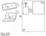
- FIG. 2A there is provided a schematic illustration of one embodiment of the present invention.
- Fig. 2A illustrates a configurable universal isolator 201 of the present invention as an example of the configurable functional device and which employs a micro system control element 211 for use in part of the configuration process.
- isolator 201 employs an RFID unit having a small antenna, commonly in the order of 10mm, and also offering non-volatile storage functionality.
- the communication of configurable data to, and the transmission of configured data from, the universal isolator 201 is employed in a wireless manner and by means of particularly cost effective, and generally readily available, communication devices such as a known smart phone 221, and laptop 222 and indeed other devices such as communication-enabled tablet devices.
- FIG. 2B there is illustrated the employment of such an isolator 201 of the present invention as a mounting of seven isolator devices 201-207 in which one isolator device 205 is selected, and again as indicated by illuminated LED 245 for appropriate wireless/remote configuration by way of its RFID device (not shown in Fig. 2B ) and an operative's smartphone 221.
- the ability to communicate to the microprocessor control element 211 of the isolator 201 of the present invention allows an operator to configure the isolator 201 at a distance, in any situation, while powered or not, whether on an assembly bench, test bench, whether in an operatives hand, or generally on the fly production or when mounted in the field.
- the configuration unit can therefore readily be incorporated within widely available communication devices such as smartphones which can readily be arranged for communication with an RFID chip and which provide for particularly cost effective alternatives to the use of known EEPROMs and connectors as found in the prior art.
- the invention is not restricted to the exact details of the foregoing embodiment and the remote communication with the configurable isolator device can be by way of any appropriate wireless transmission/reception technology an including those employing Near Field Communication (NFC) communication protocols or otherwise.
- NFC Near Field Communication
- the configuration can therefore be advantageously memorised even when the unit is turned off. Also, no direct contact is required with the isolator device due to the use of the transmission/reception of wireless configuration data and so the configuration and subsequent inspection, process can be achieved in a more reliable and efficient manner and, in particular, in a manner not exhibiting EMC issues for the operative.
- an isolator is an intrinsically safe device and if it is mounted in a zone of danger, for ex. Zone 2, while a connector based configuration/communication would be forbidden during operation, such a type of communication as herein described would be allowed.
Landscapes
- Engineering & Computer Science (AREA)
- Software Systems (AREA)
- Physics & Mathematics (AREA)
- Theoretical Computer Science (AREA)
- Electromagnetism (AREA)
- Computer Networks & Wireless Communication (AREA)
- Signal Processing (AREA)
- General Engineering & Computer Science (AREA)
- General Physics & Mathematics (AREA)
- Arrangements For Transmission Of Measured Signals (AREA)
- Emergency Protection Circuit Devices (AREA)
- Programmable Controllers (AREA)
- Telephone Set Structure (AREA)
Applications Claiming Priority (2)
| Application Number | Priority Date | Filing Date | Title |
|---|---|---|---|
| GBGB1603207.0A GB201603207D0 (en) | 2016-02-24 | 2016-02-24 | Electronic device configuration |
| PCT/GB2017/050188 WO2017144846A1 (en) | 2016-02-24 | 2017-01-25 | Electronic device configuration |
Publications (2)
| Publication Number | Publication Date |
|---|---|
| EP3420622A1 EP3420622A1 (en) | 2019-01-02 |
| EP3420622B1 true EP3420622B1 (en) | 2023-07-19 |
Family
ID=55753121
Family Applications (1)
| Application Number | Title | Priority Date | Filing Date |
|---|---|---|---|
| EP17707092.7A Active EP3420622B1 (en) | 2016-02-24 | 2017-01-25 | Electronic device configuration |
Country Status (7)
Families Citing this family (1)
| Publication number | Priority date | Publication date | Assignee | Title |
|---|---|---|---|---|
| EP3416486B1 (en) | 2016-06-21 | 2019-05-22 | Battelle UK Limited | Liquid sulfonylurea- and li-salt containing herbicidal compositions |
Citations (2)
| Publication number | Priority date | Publication date | Assignee | Title |
|---|---|---|---|---|
| US20070247768A1 (en) * | 2006-04-21 | 2007-10-25 | Square D Company | Wireless handheld device and circuit breaker |
| US20150099464A1 (en) * | 2013-10-03 | 2015-04-09 | Schneider Electric Industries Sas | Switching device and a method of controlling the same |
Family Cites Families (32)
| Publication number | Priority date | Publication date | Assignee | Title |
|---|---|---|---|---|
| US1815233A (en) | 1927-07-11 | 1931-07-21 | Burke Electric Company | Terminal block |
| US4099216A (en) | 1976-11-12 | 1978-07-04 | Westinghouse Electric Corp. | Fuseless intrinsic safety barrier |
| US5144517A (en) | 1989-10-20 | 1992-09-01 | Pepperl + Fuchs, Inc. | Intrinsically safe barrier device |
| IT1244115B (it) | 1990-11-29 | 1994-07-05 | Elcon Instr Srl | Sistema di connessione per cavi di quadri industriali di strumentazione a sicurezza intrinseca |
| US5564086A (en) * | 1993-11-29 | 1996-10-08 | Motorola, Inc. | Method and apparatus for enhancing an operating characteristic of a radio transmitter |
| US6054780A (en) | 1997-10-23 | 2000-04-25 | Analog Devices, Inc. | Magnetically coupled signal isolator using a Faraday shielded MR or GMR receiving element |
| SE514237C2 (sv) * | 1998-02-26 | 2001-01-29 | Ericsson Telefon Ab L M | Utbytbart kontaktdon för inbördes roterande enheter och en bärbar anordning försedd med sådant kontaktdon |
| DE19829528C1 (de) | 1998-07-02 | 2000-02-24 | Ulrich Weitzel | Leitungsverteiler für fernmelde- und sicherheitstechnische Anlagen |
| US6384350B1 (en) | 1999-08-02 | 2002-05-07 | Meter Devices Company | Meter test switch |
| US6885949B2 (en) | 2002-07-24 | 2005-04-26 | Smar Research Corporation | System and method for measuring system parameters and process variables using multiple sensors which are isolated by an intrinsically safe barrier |
| EP1618712A2 (en) * | 2003-04-30 | 2006-01-25 | Analog Devices, Inc. | Signal isolators using micro-transformers |
| JP4532856B2 (ja) | 2003-07-08 | 2010-08-25 | キヤノン株式会社 | 位置姿勢計測方法及び装置 |
| US7148738B2 (en) * | 2004-02-17 | 2006-12-12 | Siemens Energy & Automation, Inc. | Systems, devices, and methods for providing control signals |
| JP2005333169A (ja) * | 2004-05-18 | 2005-12-02 | Sony Corp | 無線通信システム及び無線通信装置 |
| US8441325B2 (en) * | 2004-06-03 | 2013-05-14 | Silicon Laboratories Inc. | Isolator with complementary configurable memory |
| US20060202443A1 (en) | 2005-03-09 | 2006-09-14 | The Holland Group, Inc. | Fifth wheel slider assembly |
| US7825776B2 (en) | 2006-08-17 | 2010-11-02 | Intel Corporation | Device configuration with RFID |
| GB0816121D0 (en) * | 2008-09-04 | 2008-10-15 | Mtl Instr Group The Plc | Multispur fieldbus barrier arrangement |
| US8212388B2 (en) | 2008-11-07 | 2012-07-03 | International Business Machines Corporation | Multi-capacity power supply for electronic devices |
| TW201032059A (en) * | 2009-02-27 | 2010-09-01 | Io Interconnect Ltd | Configurable wireless universal serial bus (USB) module |
| US9035766B2 (en) | 2010-07-07 | 2015-05-19 | Honeywell International Inc. | System and method of determining gas detector information and status via RFID tags |
| JP5087666B2 (ja) * | 2010-09-30 | 2012-12-05 | 株式会社東芝 | 情報処理装置及び通信制御方法 |
| EP2701255B1 (en) | 2012-08-23 | 2016-05-04 | General Electric Technology GmbH | Circuit interruption device |
| CN203084479U (zh) * | 2013-01-15 | 2013-07-24 | 西安文理学院 | 一种隔离式安全栅 |
| GB201304957D0 (en) | 2013-03-19 | 2013-05-01 | Kitchener Renato | New generation fieldbus self organising power system |
| US9565744B2 (en) * | 2013-08-19 | 2017-02-07 | Philips Lighting Holding B.V. | Programmable lighting device and method and system for programming lighting device |
| US20150065065A1 (en) * | 2013-09-03 | 2015-03-05 | Broadcom Corporation | Rf transceiver with isolation transformer and methods for use therewith |
| CN104615093B (zh) | 2013-10-28 | 2018-04-20 | 费希尔控制国际公司 | 本质安全电压钳制设备 |
| US20150296598A1 (en) | 2014-04-11 | 2015-10-15 | Infineon Technologies Ag | Contactless Device Configuration |
| WO2015161130A2 (en) * | 2014-04-18 | 2015-10-22 | Gentex Corporation | Trainable transceiver and mobile communications device diagnostic systems and methods |
| US9946240B2 (en) | 2015-01-30 | 2018-04-17 | Fisher-Rosemount Systems, Inc. | Apparatus to communicatively couple three-wire field devices to controllers in a process control system |
| GB201603108D0 (en) * | 2016-02-23 | 2016-04-06 | Cooper Technologies Co | Configurable isolator |
-
2016
- 2016-02-24 GB GBGB1603207.0A patent/GB201603207D0/en not_active Ceased
-
2017
- 2017-01-25 EP EP17707092.7A patent/EP3420622B1/en active Active
- 2017-01-25 US US16/079,875 patent/US10811872B2/en active Active
- 2017-01-25 RU RU2018132672A patent/RU2704250C1/ru active
- 2017-01-25 WO PCT/GB2017/050188 patent/WO2017144846A1/en active Application Filing
- 2017-01-25 CN CN201780021907.8A patent/CN108886250B/zh active Active
- 2017-01-25 JP JP2018544778A patent/JP7174628B2/ja active Active
-
2020
- 2020-09-28 US US17/034,358 patent/US11316339B2/en active Active
Patent Citations (2)
| Publication number | Priority date | Publication date | Assignee | Title |
|---|---|---|---|---|
| US20070247768A1 (en) * | 2006-04-21 | 2007-10-25 | Square D Company | Wireless handheld device and circuit breaker |
| US20150099464A1 (en) * | 2013-10-03 | 2015-04-09 | Schneider Electric Industries Sas | Switching device and a method of controlling the same |
Also Published As
| Publication number | Publication date |
|---|---|
| US11316339B2 (en) | 2022-04-26 |
| US10811872B2 (en) | 2020-10-20 |
| US20190027926A1 (en) | 2019-01-24 |
| CN108886250A (zh) | 2018-11-23 |
| RU2704250C1 (ru) | 2019-10-25 |
| JP7174628B2 (ja) | 2022-11-17 |
| WO2017144846A1 (en) | 2017-08-31 |
| GB201603207D0 (en) | 2016-04-06 |
| CN108886250B (zh) | 2020-12-22 |
| US20210013710A1 (en) | 2021-01-14 |
| EP3420622A1 (en) | 2019-01-02 |
| JP2019519012A (ja) | 2019-07-04 |
Similar Documents
| Publication | Publication Date | Title |
|---|---|---|
| CN101636890B (zh) | 用于利用rfid功能映射连接的系统 | |
| US8713342B2 (en) | System and method for efficient association of a power outlet and device | |
| RU2735582C1 (ru) | Программируемый разъем | |
| JP6568115B2 (ja) | ワイヤレス・モジュールとアンテナとを接続するための、組込型の容量性バリヤを伴う本質的安全インライン・アダプター | |
| CN101785078A (zh) | 在电气低压开关设备中识别组件的方法 | |
| US9530584B2 (en) | Common switch device for vehicle | |
| CN104718506A (zh) | 用于发射和/或接收现场装置的测量数据的设备以及系统 | |
| US11778072B2 (en) | Control and data transfer system for supporting different communication protocols and an adapter module | |
| CN109416527B (zh) | 自动化部件的系统及其运行方法 | |
| US11316339B2 (en) | Electronic device configuration | |
| CA2722920C (en) | System and method for efficient association of a power outlet and device | |
| JP7109376B2 (ja) | 電子デバイス切断 | |
| US11209785B2 (en) | Front adapter for connecting to a control device and automation system | |
| ES2661020T3 (es) | Sistema y procedimiento para la configuración y/o parametrización inalámbrica de pequeños aparatos de control | |
| US11070011B2 (en) | Remotely configurable connector | |
| US10915127B2 (en) | Parameterizable energy supply device | |
| US20160049787A1 (en) | Power socket apparatus with short distance communication function | |
| CN112805643A (zh) | 用于无线数据传送的现场设备适配器 | |
| KR101916678B1 (ko) | 피엘씨 | |
| KR20150000685A (ko) | 송수신 점등 표시구조를 갖는 분기 케이블 | |
| KR20120078920A (ko) | 로터리 방식의 콘솔 연결 장치 |
Legal Events
| Date | Code | Title | Description |
|---|---|---|---|
| STAA | Information on the status of an ep patent application or granted ep patent |
Free format text: STATUS: UNKNOWN |
|
| STAA | Information on the status of an ep patent application or granted ep patent |
Free format text: STATUS: THE INTERNATIONAL PUBLICATION HAS BEEN MADE |
|
| PUAI | Public reference made under article 153(3) epc to a published international application that has entered the european phase |
Free format text: ORIGINAL CODE: 0009012 |
|
| STAA | Information on the status of an ep patent application or granted ep patent |
Free format text: STATUS: REQUEST FOR EXAMINATION WAS MADE |
|
| 17P | Request for examination filed |
Effective date: 20180921 |
|
| AK | Designated contracting states |
Kind code of ref document: A1 Designated state(s): AL AT BE BG CH CY CZ DE DK EE ES FI FR GB GR HR HU IE IS IT LI LT LU LV MC MK MT NL NO PL PT RO RS SE SI SK SM TR |
|
| AX | Request for extension of the european patent |
Extension state: BA ME |
|
| DAV | Request for validation of the european patent (deleted) | ||
| DAX | Request for extension of the european patent (deleted) | ||
| STAA | Information on the status of an ep patent application or granted ep patent |
Free format text: STATUS: EXAMINATION IS IN PROGRESS |
|
| 17Q | First examination report despatched |
Effective date: 20190819 |
|
| STAA | Information on the status of an ep patent application or granted ep patent |
Free format text: STATUS: EXAMINATION IS IN PROGRESS |
|
| GRAP | Despatch of communication of intention to grant a patent |
Free format text: ORIGINAL CODE: EPIDOSNIGR1 |
|
| STAA | Information on the status of an ep patent application or granted ep patent |
Free format text: STATUS: GRANT OF PATENT IS INTENDED |
|
| RIC1 | Information provided on ipc code assigned before grant |
Ipc: H04B 5/00 20060101ALI20230328BHEP Ipc: H02H 3/00 20060101ALI20230328BHEP Ipc: H02H 1/00 20060101ALI20230328BHEP Ipc: H02H 9/00 20060101AFI20230328BHEP |
|
| INTG | Intention to grant announced |
Effective date: 20230414 |
|
| GRAS | Grant fee paid |
Free format text: ORIGINAL CODE: EPIDOSNIGR3 |
|
| GRAA | (expected) grant |
Free format text: ORIGINAL CODE: 0009210 |
|
| STAA | Information on the status of an ep patent application or granted ep patent |
Free format text: STATUS: THE PATENT HAS BEEN GRANTED |
|
| P01 | Opt-out of the competence of the unified patent court (upc) registered |
Effective date: 20230521 |
|
| AK | Designated contracting states |
Kind code of ref document: B1 Designated state(s): AL AT BE BG CH CY CZ DE DK EE ES FI FR GB GR HR HU IE IS IT LI LT LU LV MC MK MT NL NO PL PT RO RS SE SI SK SM TR |
|
| REG | Reference to a national code |
Ref country code: GB Ref legal event code: FG4D |
|
| REG | Reference to a national code |
Ref country code: CH Ref legal event code: EP |
|
| REG | Reference to a national code |
Ref country code: DE Ref legal event code: R096 Ref document number: 602017071435 Country of ref document: DE |
|
| REG | Reference to a national code |
Ref country code: IE Ref legal event code: FG4D |
|
| REG | Reference to a national code |
Ref country code: LT Ref legal event code: MG9D |
|
| REG | Reference to a national code |
Ref country code: NL Ref legal event code: MP Effective date: 20230719 |
|
| REG | Reference to a national code |
Ref country code: NO Ref legal event code: T2 Effective date: 20230719 |
|
| REG | Reference to a national code |
Ref country code: AT Ref legal event code: MK05 Ref document number: 1590455 Country of ref document: AT Kind code of ref document: T Effective date: 20230719 |
|
| PG25 | Lapsed in a contracting state [announced via postgrant information from national office to epo] |
Ref country code: NL Free format text: LAPSE BECAUSE OF FAILURE TO SUBMIT A TRANSLATION OF THE DESCRIPTION OR TO PAY THE FEE WITHIN THE PRESCRIBED TIME-LIMIT Effective date: 20230719 |
|
| PG25 | Lapsed in a contracting state [announced via postgrant information from national office to epo] |
Ref country code: GR Free format text: LAPSE BECAUSE OF FAILURE TO SUBMIT A TRANSLATION OF THE DESCRIPTION OR TO PAY THE FEE WITHIN THE PRESCRIBED TIME-LIMIT Effective date: 20231020 |
|
| PG25 | Lapsed in a contracting state [announced via postgrant information from national office to epo] |
Ref country code: IS Free format text: LAPSE BECAUSE OF FAILURE TO SUBMIT A TRANSLATION OF THE DESCRIPTION OR TO PAY THE FEE WITHIN THE PRESCRIBED TIME-LIMIT Effective date: 20231119 |
|
| PG25 | Lapsed in a contracting state [announced via postgrant information from national office to epo] |
Ref country code: SE Free format text: LAPSE BECAUSE OF FAILURE TO SUBMIT A TRANSLATION OF THE DESCRIPTION OR TO PAY THE FEE WITHIN THE PRESCRIBED TIME-LIMIT Effective date: 20230719 Ref country code: RS Free format text: LAPSE BECAUSE OF FAILURE TO SUBMIT A TRANSLATION OF THE DESCRIPTION OR TO PAY THE FEE WITHIN THE PRESCRIBED TIME-LIMIT Effective date: 20230719 Ref country code: PT Free format text: LAPSE BECAUSE OF FAILURE TO SUBMIT A TRANSLATION OF THE DESCRIPTION OR TO PAY THE FEE WITHIN THE PRESCRIBED TIME-LIMIT Effective date: 20231120 Ref country code: LV Free format text: LAPSE BECAUSE OF FAILURE TO SUBMIT A TRANSLATION OF THE DESCRIPTION OR TO PAY THE FEE WITHIN THE PRESCRIBED TIME-LIMIT Effective date: 20230719 Ref country code: LT Free format text: LAPSE BECAUSE OF FAILURE TO SUBMIT A TRANSLATION OF THE DESCRIPTION OR TO PAY THE FEE WITHIN THE PRESCRIBED TIME-LIMIT Effective date: 20230719 Ref country code: IS Free format text: LAPSE BECAUSE OF FAILURE TO SUBMIT A TRANSLATION OF THE DESCRIPTION OR TO PAY THE FEE WITHIN THE PRESCRIBED TIME-LIMIT Effective date: 20231119 Ref country code: HR Free format text: LAPSE BECAUSE OF FAILURE TO SUBMIT A TRANSLATION OF THE DESCRIPTION OR TO PAY THE FEE WITHIN THE PRESCRIBED TIME-LIMIT Effective date: 20230719 Ref country code: GR Free format text: LAPSE BECAUSE OF FAILURE TO SUBMIT A TRANSLATION OF THE DESCRIPTION OR TO PAY THE FEE WITHIN THE PRESCRIBED TIME-LIMIT Effective date: 20231020 Ref country code: FI Free format text: LAPSE BECAUSE OF FAILURE TO SUBMIT A TRANSLATION OF THE DESCRIPTION OR TO PAY THE FEE WITHIN THE PRESCRIBED TIME-LIMIT Effective date: 20230719 Ref country code: AT Free format text: LAPSE BECAUSE OF FAILURE TO SUBMIT A TRANSLATION OF THE DESCRIPTION OR TO PAY THE FEE WITHIN THE PRESCRIBED TIME-LIMIT Effective date: 20230719 |
|
| PG25 | Lapsed in a contracting state [announced via postgrant information from national office to epo] |
Ref country code: PL Free format text: LAPSE BECAUSE OF FAILURE TO SUBMIT A TRANSLATION OF THE DESCRIPTION OR TO PAY THE FEE WITHIN THE PRESCRIBED TIME-LIMIT Effective date: 20230719 |
|
| REG | Reference to a national code |
Ref country code: DE Ref legal event code: R097 Ref document number: 602017071435 Country of ref document: DE |
|
| PG25 | Lapsed in a contracting state [announced via postgrant information from national office to epo] |
Ref country code: ES Free format text: LAPSE BECAUSE OF FAILURE TO SUBMIT A TRANSLATION OF THE DESCRIPTION OR TO PAY THE FEE WITHIN THE PRESCRIBED TIME-LIMIT Effective date: 20230719 |
|
| PG25 | Lapsed in a contracting state [announced via postgrant information from national office to epo] |
Ref country code: SM Free format text: LAPSE BECAUSE OF FAILURE TO SUBMIT A TRANSLATION OF THE DESCRIPTION OR TO PAY THE FEE WITHIN THE PRESCRIBED TIME-LIMIT Effective date: 20230719 Ref country code: RO Free format text: LAPSE BECAUSE OF FAILURE TO SUBMIT A TRANSLATION OF THE DESCRIPTION OR TO PAY THE FEE WITHIN THE PRESCRIBED TIME-LIMIT Effective date: 20230719 Ref country code: ES Free format text: LAPSE BECAUSE OF FAILURE TO SUBMIT A TRANSLATION OF THE DESCRIPTION OR TO PAY THE FEE WITHIN THE PRESCRIBED TIME-LIMIT Effective date: 20230719 Ref country code: EE Free format text: LAPSE BECAUSE OF FAILURE TO SUBMIT A TRANSLATION OF THE DESCRIPTION OR TO PAY THE FEE WITHIN THE PRESCRIBED TIME-LIMIT Effective date: 20230719 Ref country code: DK Free format text: LAPSE BECAUSE OF FAILURE TO SUBMIT A TRANSLATION OF THE DESCRIPTION OR TO PAY THE FEE WITHIN THE PRESCRIBED TIME-LIMIT Effective date: 20230719 Ref country code: CZ Free format text: LAPSE BECAUSE OF FAILURE TO SUBMIT A TRANSLATION OF THE DESCRIPTION OR TO PAY THE FEE WITHIN THE PRESCRIBED TIME-LIMIT Effective date: 20230719 Ref country code: SK Free format text: LAPSE BECAUSE OF FAILURE TO SUBMIT A TRANSLATION OF THE DESCRIPTION OR TO PAY THE FEE WITHIN THE PRESCRIBED TIME-LIMIT Effective date: 20230719 |
|
| PLBE | No opposition filed within time limit |
Free format text: ORIGINAL CODE: 0009261 |
|
| STAA | Information on the status of an ep patent application or granted ep patent |
Free format text: STATUS: NO OPPOSITION FILED WITHIN TIME LIMIT |
|
| 26N | No opposition filed |
Effective date: 20240422 |
|
| PG25 | Lapsed in a contracting state [announced via postgrant information from national office to epo] |
Ref country code: SI Free format text: LAPSE BECAUSE OF FAILURE TO SUBMIT A TRANSLATION OF THE DESCRIPTION OR TO PAY THE FEE WITHIN THE PRESCRIBED TIME-LIMIT Effective date: 20230719 |
|
| PG25 | Lapsed in a contracting state [announced via postgrant information from national office to epo] |
Ref country code: MC Free format text: LAPSE BECAUSE OF FAILURE TO SUBMIT A TRANSLATION OF THE DESCRIPTION OR TO PAY THE FEE WITHIN THE PRESCRIBED TIME-LIMIT Effective date: 20230719 |
|
| PG25 | Lapsed in a contracting state [announced via postgrant information from national office to epo] |
Ref country code: MC Free format text: LAPSE BECAUSE OF FAILURE TO SUBMIT A TRANSLATION OF THE DESCRIPTION OR TO PAY THE FEE WITHIN THE PRESCRIBED TIME-LIMIT Effective date: 20230719 |
|
| REG | Reference to a national code |
Ref country code: CH Ref legal event code: PL |
|
| PG25 | Lapsed in a contracting state [announced via postgrant information from national office to epo] |
Ref country code: LU Free format text: LAPSE BECAUSE OF NON-PAYMENT OF DUE FEES Effective date: 20240125 |
|
| PG25 | Lapsed in a contracting state [announced via postgrant information from national office to epo] |
Ref country code: LU Free format text: LAPSE BECAUSE OF NON-PAYMENT OF DUE FEES Effective date: 20240125 |
|
| PG25 | Lapsed in a contracting state [announced via postgrant information from national office to epo] |
Ref country code: BE Free format text: LAPSE BECAUSE OF NON-PAYMENT OF DUE FEES Effective date: 20240131 |
|
| PG25 | Lapsed in a contracting state [announced via postgrant information from national office to epo] |
Ref country code: CH Free format text: LAPSE BECAUSE OF NON-PAYMENT OF DUE FEES Effective date: 20240131 |
|
| PG25 | Lapsed in a contracting state [announced via postgrant information from national office to epo] |
Ref country code: CH Free format text: LAPSE BECAUSE OF NON-PAYMENT OF DUE FEES Effective date: 20240131 Ref country code: BE Free format text: LAPSE BECAUSE OF NON-PAYMENT OF DUE FEES Effective date: 20240131 |
|
| REG | Reference to a national code |
Ref country code: BE Ref legal event code: MM Effective date: 20240131 |
|
| PG25 | Lapsed in a contracting state [announced via postgrant information from national office to epo] |
Ref country code: BG Free format text: LAPSE BECAUSE OF FAILURE TO SUBMIT A TRANSLATION OF THE DESCRIPTION OR TO PAY THE FEE WITHIN THE PRESCRIBED TIME-LIMIT Effective date: 20230719 |
|
| PG25 | Lapsed in a contracting state [announced via postgrant information from national office to epo] |
Ref country code: BG Free format text: LAPSE BECAUSE OF FAILURE TO SUBMIT A TRANSLATION OF THE DESCRIPTION OR TO PAY THE FEE WITHIN THE PRESCRIBED TIME-LIMIT Effective date: 20230719 |
|
| PGFP | Annual fee paid to national office [announced via postgrant information from national office to epo] |
Ref country code: NO Payment date: 20241219 Year of fee payment: 9 |
|
| PGFP | Annual fee paid to national office [announced via postgrant information from national office to epo] |
Ref country code: GB Payment date: 20241219 Year of fee payment: 9 |
|
| PGFP | Annual fee paid to national office [announced via postgrant information from national office to epo] |
Ref country code: FR Payment date: 20241220 Year of fee payment: 9 |
|
| PG25 | Lapsed in a contracting state [announced via postgrant information from national office to epo] |
Ref country code: IE Free format text: LAPSE BECAUSE OF NON-PAYMENT OF DUE FEES Effective date: 20240125 |
|
| PG25 | Lapsed in a contracting state [announced via postgrant information from national office to epo] |
Ref country code: IE Free format text: LAPSE BECAUSE OF NON-PAYMENT OF DUE FEES Effective date: 20240125 |
|
| PGFP | Annual fee paid to national office [announced via postgrant information from national office to epo] |
Ref country code: DE Payment date: 20241218 Year of fee payment: 9 |
|
| PGFP | Annual fee paid to national office [announced via postgrant information from national office to epo] |
Ref country code: IT Payment date: 20250107 Year of fee payment: 9 |
|
| PG25 | Lapsed in a contracting state [announced via postgrant information from national office to epo] |
Ref country code: CY Free format text: LAPSE BECAUSE OF FAILURE TO SUBMIT A TRANSLATION OF THE DESCRIPTION OR TO PAY THE FEE WITHIN THE PRESCRIBED TIME-LIMIT; INVALID AB INITIO Effective date: 20170125 |
|
| PG25 | Lapsed in a contracting state [announced via postgrant information from national office to epo] |
Ref country code: HU Free format text: LAPSE BECAUSE OF FAILURE TO SUBMIT A TRANSLATION OF THE DESCRIPTION OR TO PAY THE FEE WITHIN THE PRESCRIBED TIME-LIMIT; INVALID AB INITIO Effective date: 20170125 |