EP3420604B1 - Zellmodul für eine batterie eines kraftfahrzeugs sowie verfahren zum herstellen eines solchen zellmoduls - Google Patents
Zellmodul für eine batterie eines kraftfahrzeugs sowie verfahren zum herstellen eines solchen zellmoduls Download PDFInfo
- Publication number
- EP3420604B1 EP3420604B1 EP17707783.1A EP17707783A EP3420604B1 EP 3420604 B1 EP3420604 B1 EP 3420604B1 EP 17707783 A EP17707783 A EP 17707783A EP 3420604 B1 EP3420604 B1 EP 3420604B1
- Authority
- EP
- European Patent Office
- Prior art keywords
- cell module
- battery cells
- battery
- tension rod
- pressure elements
- Prior art date
- Legal status (The legal status is an assumption and is not a legal conclusion. Google has not performed a legal analysis and makes no representation as to the accuracy of the status listed.)
- Active
Links
Images

Classifications
-
- H—ELECTRICITY
- H01—ELECTRIC ELEMENTS
- H01M—PROCESSES OR MEANS, e.g. BATTERIES, FOR THE DIRECT CONVERSION OF CHEMICAL ENERGY INTO ELECTRICAL ENERGY
- H01M10/00—Secondary cells; Manufacture thereof
- H01M10/04—Construction or manufacture in general
- H01M10/0481—Compression means other than compression means for stacks of electrodes and separators
-
- B—PERFORMING OPERATIONS; TRANSPORTING
- B60—VEHICLES IN GENERAL
- B60L—PROPULSION OF ELECTRICALLY-PROPELLED VEHICLES; SUPPLYING ELECTRIC POWER FOR AUXILIARY EQUIPMENT OF ELECTRICALLY-PROPELLED VEHICLES; ELECTRODYNAMIC BRAKE SYSTEMS FOR VEHICLES IN GENERAL; MAGNETIC SUSPENSION OR LEVITATION FOR VEHICLES; MONITORING OPERATING VARIABLES OF ELECTRICALLY-PROPELLED VEHICLES; ELECTRIC SAFETY DEVICES FOR ELECTRICALLY-PROPELLED VEHICLES
- B60L50/00—Electric propulsion with power supplied within the vehicle
- B60L50/50—Electric propulsion with power supplied within the vehicle using propulsion power supplied by batteries or fuel cells
- B60L50/60—Electric propulsion with power supplied within the vehicle using propulsion power supplied by batteries or fuel cells using power supplied by batteries
- B60L50/66—Arrangements of batteries
-
- H—ELECTRICITY
- H01—ELECTRIC ELEMENTS
- H01M—PROCESSES OR MEANS, e.g. BATTERIES, FOR THE DIRECT CONVERSION OF CHEMICAL ENERGY INTO ELECTRICAL ENERGY
- H01M50/00—Constructional details or processes of manufacture of the non-active parts of electrochemical cells other than fuel cells, e.g. hybrid cells
- H01M50/20—Mountings; Secondary casings or frames; Racks, modules or packs; Suspension devices; Shock absorbers; Transport or carrying devices; Holders
- H01M50/204—Racks, modules or packs for multiple batteries or multiple cells
- H01M50/207—Racks, modules or packs for multiple batteries or multiple cells characterised by their shape
- H01M50/209—Racks, modules or packs for multiple batteries or multiple cells characterised by their shape adapted for prismatic or rectangular cells
-
- H—ELECTRICITY
- H01—ELECTRIC ELEMENTS
- H01M—PROCESSES OR MEANS, e.g. BATTERIES, FOR THE DIRECT CONVERSION OF CHEMICAL ENERGY INTO ELECTRICAL ENERGY
- H01M50/00—Constructional details or processes of manufacture of the non-active parts of electrochemical cells other than fuel cells, e.g. hybrid cells
- H01M50/20—Mountings; Secondary casings or frames; Racks, modules or packs; Suspension devices; Shock absorbers; Transport or carrying devices; Holders
- H01M50/262—Mountings; Secondary casings or frames; Racks, modules or packs; Suspension devices; Shock absorbers; Transport or carrying devices; Holders with fastening means, e.g. locks
- H01M50/264—Mountings; Secondary casings or frames; Racks, modules or packs; Suspension devices; Shock absorbers; Transport or carrying devices; Holders with fastening means, e.g. locks for cells or batteries, e.g. straps, tie rods or peripheral frames
-
- H—ELECTRICITY
- H01—ELECTRIC ELEMENTS
- H01M—PROCESSES OR MEANS, e.g. BATTERIES, FOR THE DIRECT CONVERSION OF CHEMICAL ENERGY INTO ELECTRICAL ENERGY
- H01M50/00—Constructional details or processes of manufacture of the non-active parts of electrochemical cells other than fuel cells, e.g. hybrid cells
- H01M50/10—Primary casings; Jackets or wrappings
- H01M50/131—Primary casings; Jackets or wrappings characterised by physical properties, e.g. gas permeability, size or heat resistance
-
- Y—GENERAL TAGGING OF NEW TECHNOLOGICAL DEVELOPMENTS; GENERAL TAGGING OF CROSS-SECTIONAL TECHNOLOGIES SPANNING OVER SEVERAL SECTIONS OF THE IPC; TECHNICAL SUBJECTS COVERED BY FORMER USPC CROSS-REFERENCE ART COLLECTIONS [XRACs] AND DIGESTS
- Y02—TECHNOLOGIES OR APPLICATIONS FOR MITIGATION OR ADAPTATION AGAINST CLIMATE CHANGE
- Y02E—REDUCTION OF GREENHOUSE GAS [GHG] EMISSIONS, RELATED TO ENERGY GENERATION, TRANSMISSION OR DISTRIBUTION
- Y02E60/00—Enabling technologies; Technologies with a potential or indirect contribution to GHG emissions mitigation
- Y02E60/10—Energy storage using batteries
-
- Y—GENERAL TAGGING OF NEW TECHNOLOGICAL DEVELOPMENTS; GENERAL TAGGING OF CROSS-SECTIONAL TECHNOLOGIES SPANNING OVER SEVERAL SECTIONS OF THE IPC; TECHNICAL SUBJECTS COVERED BY FORMER USPC CROSS-REFERENCE ART COLLECTIONS [XRACs] AND DIGESTS
- Y02—TECHNOLOGIES OR APPLICATIONS FOR MITIGATION OR ADAPTATION AGAINST CLIMATE CHANGE
- Y02P—CLIMATE CHANGE MITIGATION TECHNOLOGIES IN THE PRODUCTION OR PROCESSING OF GOODS
- Y02P70/00—Climate change mitigation technologies in the production process for final industrial or consumer products
- Y02P70/50—Manufacturing or production processes characterised by the final manufactured product
-
- Y—GENERAL TAGGING OF NEW TECHNOLOGICAL DEVELOPMENTS; GENERAL TAGGING OF CROSS-SECTIONAL TECHNOLOGIES SPANNING OVER SEVERAL SECTIONS OF THE IPC; TECHNICAL SUBJECTS COVERED BY FORMER USPC CROSS-REFERENCE ART COLLECTIONS [XRACs] AND DIGESTS
- Y02—TECHNOLOGIES OR APPLICATIONS FOR MITIGATION OR ADAPTATION AGAINST CLIMATE CHANGE
- Y02T—CLIMATE CHANGE MITIGATION TECHNOLOGIES RELATED TO TRANSPORTATION
- Y02T10/00—Road transport of goods or passengers
- Y02T10/60—Other road transportation technologies with climate change mitigation effect
- Y02T10/70—Energy storage systems for electromobility, e.g. batteries
Definitions
- the invention relates to a cell module for a battery of a motor vehicle and a method for producing such a cell module.
- Such an electrified drive train is also referred to as an alternative drive train or alternative drive and comprises at least one electrical machine which can be operated as an electric motor for driving the respective motor vehicle.
- the motor vehicle can thus be driven purely electrically.
- a drive train comprises an internal combustion engine for driving the motor vehicle, wherein the electrical machine can, for example, support the internal combustion engine when driving the motor vehicle.
- the motor vehicle is thus designed, for example, as an electric vehicle or hybrid vehicle.
- the electrical machine In order to operate the electrical machine in its motor mode, the electrical machine must be supplied with electrical current or electrical energy.
- at least one electrical energy store in the form of a battery is used for this purpose, by means of which electrical energy can be stored.
- the electrical machine can be supplied with electrical energy stored in the electrical energy store in its motor operation.
- Such an electrified drive train is usually heavy and expensive.
- the WO 2012/120107 A1 discloses an electrical energy store for motor vehicles, with at least one battery module with several individual modules each having at least one cell.
- the individual modules are arranged in a stack between two outer end plates. It is provided that the battery module is wrapped by at least one tension band, the cells being pressed together by the end plates.
- the object of the present invention is therefore to create a cell module and a method for producing such a cell module, so that the weight and the cost of electrified drive trains for motor vehicles can be kept particularly low.
- a first aspect of the invention relates to a cell module for a battery of a motor vehicle, in particular a motor vehicle such as, for example, a passenger car.
- the cell module comprises a plurality of battery cells for storing electrical energy or electrical current.
- the cell module can thus be used in an electrified drive train which, for example, comprises at least one electrical machine in its completely manufactured state.
- the electrical machine can be operated, for example, in a motor mode and thus as an electric motor, by means of which the motor vehicle can be driven.
- the electrical machine is supplied with electrical energy stored in the battery and thus in the cell module or in the battery cells.
- the cell module further comprises a module frame which comprises at least two pressure elements and at least one tension anchor which is subjected to tension and is formed from a material.
- the battery cells are arranged between the pressure elements.
- the pressure elements are arranged, for example, at a distance from one another in a direction, the battery cells being arranged, for example, in succession or in succession along the direction and in the process between the pressure elements.
- the tie rod By means of the tie rod, the pressure elements are tensioned against one another by means of the battery cells, as a result of which the battery cells are pressed.
- the pressure elements are connected to one another via the tension anchor loaded under tension, so that the battery cells arranged between the pressure elements are pressed.
- the fact that the Tie rod is loaded after train, the battery cells are pressed together or pressed together by means of the pressure elements.
- the pressure plates are tensioned against each other by means of the tie rod in such a way that a yield point or the 0.2% proof limit of the material of the tie rod is reached.
- the tie rod for tensioning the pressure elements against one another and thus for compressing the battery cells is loaded in such a way that the yield strength or the 0.2% yield strength of the material of the tie rod is reached.
- the material of the tie rod is, for example, a metallic material, in particular a light metal or a light metal alloy such as aluminum or an aluminum alloy, so that the battery cells can be pressed particularly well and the weight and costs can be kept particularly low.
- the invention is based in particular on the idea of utilizing or choosing elastic properties of the material in such a way that, for example, cyclic loads occurring during the life of the cell module are cushioned or absorbed or compensated for by pure tensile elastic properties of the material , whereas an age-related increase in the length of the cell module is now specifically maintained by plastic deformation of the tie rod.
- the pressure plates are preferably tensioned against one another by means of the tie rod in such a way that the yield strength or the 0.2% yield strength of the material of the tie rod is exactly reached, that is to say that the tie rod or its material is exactly up to the yield point or 0.2%.
- - Yield stress is loaded. If, for example, the battery cells expand during the lifespan of the cell module, in particular along the aforementioned direction, along which the pressure elements are spaced apart, there is an increasing expansion of the tie rod.
- each further incremental expansion of the tie rod leads to a plastic deformation of the tie rod, this plastic deformation until the end of the Lifetime should not or should not lead to a constriction in the material of the tie rod.
- This ensures that a clamping force caused by the tie rod for pressing the battery cells remains at least almost constant during the service life. In other words, an at least approximately similar load on the battery cells can be ensured over the service life. In this way, variable mechanical loads on the battery cells over the service life can be avoided.
- the material or material properties of the tie rod can be used at least almost completely, so that a weight and cost-intensive oversizing of the tie rod and thus the module frame as a whole can be avoided. As a result, the weight and costs can be kept low.
- the yield point is usually referred to as R e and is a material characteristic value and denotes the stress up to which the material shows no permanent plastic deformation under uniaxial and torque-free tensile stress. It is a yield point.
- the battery cells arranged between the pressure elements and, for example, arranged one behind the other or in succession form a battery pack, the length of which can increase, for example, due to aging. As a result of this increase in length - starting from the yield strength or the 0.2% yield strength - the load acting on the tie rod or the elongation of the tie rod increases, so that the tie rod is plastically deformed.
- the yield strength or the 0.2% yield strength is reached when the battery cells are fully charged.
- a defined state is created, from which a desired plastic deformation of the tie rod occurs when the length of the battery pack increases.
- this embodiment makes it possible to cushion or absorb or compensate for cyclical loads in a purely tension-elastic manner. If, for example, there is a decrease or decrease in length of the battery pack based on the fully charged state of the battery cells, whereupon the battery pack increases in length in such a way that the yield strength or the 0.2% yield strength is not exceeded, these length changes can occur elastic, in particular tension-elastic, that is to say taken up by elastic deformation of the tension anchor. In the case of age-related increases in length starting from the yield strength or the 0.2% yield strength, however, the yield strength or 0.2% yield strength is exceeded, so that such increases in length are absorbed by plastic deformation of the tie rod.
- the yield point is the upper yield point, which is usually also referred to as R eH .
- R eH the upper yield point
- the aforementioned yield point is preferably the upper yield point R eH , so that the length of the battery pack increases and the elongation of the tie rod increases - Starting from the upper yield point - there is a plastic deformation of the tie rod.
- one of the pressure elements is designed as a fixed bearing which can be fixed to a component, in particular a housing, of the battery.
- the battery thus includes the cell module at least one further component, which is designed, for example, as a housing.
- the cell module is held on the further component.
- one of the pressure elements is designed as a fixed bearing, which can be fixed or fixed on the further component, in particular the housing, of the battery. In this way, a defined and secure as well as weight and cost-effective mounting of the cell module can be ensured without an excessive number of additional, weight and cost-intensive holding elements being provided and required.
- the other pressure element is designed as a floating bearing, which allows displacements of the other pressure element relative to the component of the battery.
- the other pressure element is preferably designed as a floating bearing and thus specifically displaceably mounted. In this way, tension and thus excessive loads on the cell module can be avoided, so that the cell module can be designed to be particularly lightweight and inexpensive.
- the tie rod is integrally connected to the pressure elements.
- the tie rod is welded to the pressure elements, for example.
- the pressure elements are formed from a metallic material.
- the printing elements are designed as printing plates.
- the invention also includes a battery for a motor vehicle, in particular a motor vehicle such as, for example, a passenger car, the battery having at least one cell module according to the invention.
- a battery for a motor vehicle in particular a motor vehicle such as, for example, a passenger car
- the battery having at least one cell module according to the invention.
- Advantages and advantageous configurations of the cell module according to the invention are to be regarded as advantages and advantageous configurations of the battery according to the invention and vice versa.
- a second aspect of the invention relates to a method for producing a cell module, in particular a cell module according to the invention according to the first aspect of the invention, for a battery of a motor vehicle.
- a plurality of battery cells are provided for storing electrical energy or electrical current.
- a module frame is provided which comprises at least two pressure elements and at least one tie rod formed from a material, in particular a metallic material.
- the battery cells are arranged between the pressure elements. For example, the pressure elements are arranged such that they are spaced apart from one another in one direction.
- the battery cells are arranged, for example, between the pressure elements in such a way that the battery cells are arranged one behind the other or in succession along the direction.
- the pressure elements are switched on by means of the battery cells Tie rods tensioned against each other, whereby the tie rod is loaded on train.
- the pressure plates are tensioned against each other by means of the tie rod in such a way that the material of the tie rod reaches a yield point or the 0.2% yield point, in particular exactly or exactly.
- the yield strength or the 0.2% yield strength of the material of the tie rod is preferably exactly reached immediately after the cell module has been manufactured and thus at the beginning of its service life.
- cyclic loads - in particular based on the yield strength or 0.2% yield strength - can be absorbed by elastic deformation of the tie rod, with age-related increases in length being provided by plastic deformation of the tie rod.
- the module frame is preferably loaded with fully charged battery cells exactly up to the yield point, in particular R eH , or up to the 0.2% proof limit (R p, 0.2 ).
- Each further incremental expansion of the tie rod leads to a plastic deformation of the tie rod, which ensures that a clamping force caused by the module frame and acting on the battery cells for pressing the battery cells remains at at least almost constant level.
- the battery cells are pressed by means of a pressing device that differs from the module frame.
- the battery cells are provided with the module frame in their pressed state by means of the pressing device.
- the pressure elements and the battery cells arranged between the pressure elements are pressed by means of the pressing device, so that the battery cells arranged between the pressure elements are pressed via the pressure elements by means of the pressing device and thus pressed or pressed together.
- the tie rod is coupled, in particular connected, to the pressure elements, whereupon, for example, the cell module is detached from the pressing device or whereupon the pressing effected by the pressing device is ended.
- the material of the tie rod preferably directly or immediately, reaches the yield point or the 0.2% yield point, in particular exactly or exactly, after the pressing caused by the pressing device has ended. This creates a defined initial state at the beginning of the lifespan of the cell module, on the basis of which cyclical loads due to elastic deformation, but age-related increases in length of the battery pack can be absorbed by plastic deformation of the tie rod. This means that particularly low-weight and inexpensive materials can be used for the tie rod.
- the tie rod is connected to the pressure elements in the state of the battery cell pressed by the pressing device.
- the tie rod is subjected to tensile stress, for example, only when the pressing caused by the pressing device is ended, that is to say when the pressing device is released from the cell module.
- the tie rod is thus used to maintain or cause the battery cells to be pressed after the pressing of the battery cells by the pressing device has ended, so that the tie rod is subjected to tension.
- This connection of the tie rod to the pressure elements enables a defined state and in particular a defined initial state and a defined load on the tie rod, in particular at the beginning of the life of the cell module, to be achieved.
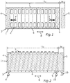
- Fig. 1 shows a schematic plan view of a cell module, generally designated 1, for a battery of a motor vehicle, in particular a motor vehicle such as, for example, a passenger car.
- the motor vehicle In its completely manufactured state, the motor vehicle has an electrified drive train which has at least one electrical machine and the aforementioned battery with the cell module 1.
- the battery In its fully manufactured state, the battery has, for example, a plurality of cell modules, of which in Fig. 1 the cell module labeled 1 is shown as a representative.
- the electric machine can be operated in a motor mode and thus as an electric motor, so that the motor vehicle can be driven by means of the electric motor.
- the electrical machine In order to operate the electrical machine in motor operation, the electrical machine must be supplied with electrical current or electrical energy.
- the battery is an electrical energy store, by means of which electrical energy or electrical current can be stored.
- the electrical machine can be supplied with electrical energy stored in the battery, in order to thereby operate the electrical machine in its motor mode.
- the cell module 1 comprises a plurality of battery cells 2, by means of which the electrical energy can be stored.
- the respective battery cell 2 comprises, for example, a cell housing in which, for example, an electrolyte of the respective battery cell 2 is accommodated.
- the cell module 1 comprises a module frame, generally designated 3, which has at least two pressure elements in the form of pressure plates 4 and 5.
- the module frame 3 comprises tension rods 6 and 7 which are subjected to tension and which are each formed from a material, in particular from a metallic material.
- Fig. 1 it can be seen that the pressure plates 4 and 5 along a in Fig. 1 are illustrated at a distance from one another illustrated by a double arrow 8.
- the battery cells 2 are arranged between the pressure plates 4 and 5 in the direction mentioned, the battery cells 2 being arranged in succession or in succession along the direction mentioned.
- the tie rods 6 and 7 By means of the tie rods 6 and 7, the pressure plates 4 and 5 are tensioned against one another by means of the battery cells 2, as a result of which the battery cells 2 are pressed.
- the tie rods 6 and 7 loaded under tension are coupled, in particular connected, to the pressure plates 4 and 5, so that the tie rods 6 and 7 loaded under tension connect the pressure plates 4 and 5 to one another, as a result of which the battery cells 2 are pressed together.
- the battery cells 2 form a battery pack, which has a length running along the direction.
- an output length of the battery pack is shown, wherein in Fig. 1 an output length L 0 of the cell module 1 is also shown.
- the, for example, convex and / or prismatic battery cells 2 are stacked on top of one another.
- the stacked battery cells 2 are, for example, pressed to a certain nominal size by means of a pressing device that is different from the cell module 1, and then clamped with the module frame 3 or in the state pressed by means of the pressing device. Then the pressing device is released. This is to be understood to mean that the pressing effected by means of the pressing device is ended.
- a restoring force of the battery cells 2, in particular via the pressure plates 4 and 5, acts on the tie rods 6 and 7 connected, in particular welded, to the pressure plates 4 and 5, so that, for example, a first, in particular elastic, elongation of the tie rods 6 and 7 or the cell module 1 as a whole takes place directly after the production.
- An elongation of the tie rods 6 and 7 or of the cell module 1 as a whole is also referred to as an increase in length.
- the aforementioned first, in particular elastic, elongation is also referred to as ⁇ assembly .
- Fig. 3 shows a stress-strain diagram of the respective material of the tie rods 6 and 7.
- the stress-strain diagram shows the tensile strength R m , the upper yield strength R eH , the lower yield strength R eL , the elongation A L , the uniform elongation A g , and the elongation A at which breakage occurs.
- the beginning of the necking is marked with E.
- To the left of the upper yield point R eH is the elastic region B of the respective tie rod 6 or 7 or of the respective material from which the respective access 6 or 7 is formed.
- the module frame 3, in particular the Tie rods 6 and 7 can, for example, be dimensioned such that all quasi-static and cyclic loads do not exceed the purely elastic area B of the material used.
- the two pressure plates 4 and 5 are designed as fixed bearings, so that the pressure plates 4 and 5 are, for example, fixed to a further component such as a housing of the battery, in particular immovably.
- a design of the module frame 3 and the pressure plates 4 and 5 as a fixed bearing is disadvantageous, as will be explained in more detail below.
- the battery cells 2 cause a cyclical load by charging and discharging during operation, this cyclical load leading to cyclical expansions or changes in length, in particular increases in length. These cyclical strains are called ⁇ SOC .
- Charging or charging the battery cells 2 and thus the battery is understood to mean that electrical energy is stored in the battery cells 2, that is to say that the battery is charged with electrical energy.
- Discharging is to be understood to mean that electrical energy stored in the battery cells 2 or in the battery is taken from the battery or is removed from the battery.
- temperature gradients act on mechanical module components, by means of which the battery cells 2 are held under tension.
- These mechanical module components are, for example, the tie rods 6 and 7 and the pressure plates 4 and 5.
- These temperature gradients bring about temperature-related changes in length or changes in elongation or expansion, which are also denoted by ⁇ T.
- These cyclical elongations or changes in length overlay an at least approximately linear increase in the length of the cell module 1 depending on its age or service life, measured, for example, on the remaining capacity of the battery, the at least approximately linear increase also being referred to as elongation or increase in length, which is also denoted by ⁇ SOH is called.
- a force acting against the module frame 3 which is also referred to as the threshold force and in Fig. 1 is illustrated by force arrows F.
- the threshold force pulls you in Fig. 1 elongation denoted by ⁇ x, that is to say the increase in length of the cell module 1 and thus the tie rods 6 and 7.
- the elongation .DELTA.x of the cell module 1 as a function of the time t and thus as a function of the service life of the cell module 1 can thus be described in a formula with: ⁇ ⁇ x t ⁇ ⁇ SOH t + ⁇ SOC C. + ⁇ T T + ⁇ Assembly
- t denotes the time, C the storage state and T the temperature or the temperature gradients mentioned.
- the battery cells 2 are pressed in such a way or that the pressure plates 4 and 5 are tensioned against one another by means of the tie rods 6 and 7 in such a way that, especially after the pressing device has been released , the upper yield point R eH or the 0.2% proof stress R p, 0.2 of the material of the tie rods 6 and 7 has been reached exactly.
- the tension rods 6 and 7 are loaded due to the tensioning of the battery cells 2 in such a way that the yield strength or the 0.2% yield strength of the material is reached exactly or precisely.
- Fig. 3 is the beginning of the life of the cell module 1 with BOL, the end of the life with EOL.
- An arrow further illustrates L in Fig. 3 the service life and thereby the behavior of the tie rods 6 and 7 during the service life or over the stretch.
- the elastic properties of the material of the tie rods 6 and 7 are used or selected in such a way that cyclical loads are cushioned in a purely tension-elastic manner.
- cyclic loads are cushioned or compensated for by elastic deformation of the tie rods 6 and 7 and thus by the elastic region B.
- the age-related increase in length .DELTA.x of the cell module 1 is specifically maintained by plastic deformation of the tie rods 6 and 7.
- the tie rods 6 and 7 are loaded exactly up to the yield strength or up to the 0.2% yield strength such that the yield strength or the 0.2% - Yield strength of the respective material of the tie rods 6 and 7 immediately after Loosening the pressing device is exactly achieved.
- the pressure plate 4 is also preferably provided to design the pressure plate 4 as a fixed bearing 9, which is fixed to the above-mentioned component, in particular to the housing, of the battery.
- the other pressure plate 5 is preferably designed as a floating bearing 10, which permits displacements of the pressure plate 5 relative to the component of the battery, in particular to the housing of the battery.
- the pressure plate 4 serves as a fixed bearing 9, while the pressure plate 5 is deliberately slidably mounted.
- Corresponding reserves for expansions are then to be kept in a targeted manner in the high-voltage battery (HV battery), for example.
- HV battery high-voltage battery
- the battery has, for example, an operating voltage of more than 50 volts, in particular more than 60 volts. In particular, the battery has an operating voltage of several 100 volts.
- the cell module 1 is illustrated in its initial length L 0 with solid lines, the elongation .DELTA.x being illustrated by broken lines.
Landscapes
- Engineering & Computer Science (AREA)
- General Chemical & Material Sciences (AREA)
- Chemical & Material Sciences (AREA)
- Chemical Kinetics & Catalysis (AREA)
- Electrochemistry (AREA)
- Life Sciences & Earth Sciences (AREA)
- Sustainable Development (AREA)
- Sustainable Energy (AREA)
- Power Engineering (AREA)
- Transportation (AREA)
- Mechanical Engineering (AREA)
- Manufacturing & Machinery (AREA)
- Battery Mounting, Suspending (AREA)
- Arrangement Or Mounting Of Propulsion Units For Vehicles (AREA)
- Secondary Cells (AREA)
Description
- Die Erfindung betrifft ein Zellmodul für eine Batterie eines Kraftfahrzeugs sowie ein Verfahren zum Herstellen eines solchen Zellmoduls.
- Aus dem allgemeinen Stand der Technik und insbesondere aus dem Serienfahrzeugbau ist es bekannt, Kraftfahrzeuge wie beispielsweise Kraftwagen mit elektrifizierten Antriebssträngen auszustatten. Ein solcher elektrifizierter Antriebsstrang wird auch als alternativer Antriebsstrang oder alternativer Antrieb bezeichnet und umfasst wenigstens eine elektrische Maschine, welche als Elektromotor zum Antreiben des jeweiligen Kraftfahrzeugs betrieben werden kann. Somit kann das Kraftfahrzeug rein elektrisch angetrieben werden. Alternativ oder zusätzlich ist es denkbar, dass ein solcher Antriebsstrang einen Verbrennungsmotor zum Antreiben des Kraftfahrzeugs umfasst, wobei die elektrische Maschine beispielsweise den Verbrennungsmotor beim Antreiben des Kraftfahrzeugs unterstützen kann. Das Kraftfahrzeug ist somit beispielsweise als Elektrofahrzeug oder Hybridfahrzeug ausgebildet.
- Um die elektrische Maschine in ihrem Motorbetrieb betreiben zu können, muss die elektrische Maschine mit elektrischem Strom beziehungsweise elektrischer Energie versorgt werden. Hierfür kommt üblicherweise wenigstens ein elektrischer Energiespeicher in Form einer Batterie zum Einsatz, mittels welcher elektrische Energie gespeichert werden kann. Die elektrische Maschine kann in ihrem Motorbetrieb mit in dem elektrischen Energiespeicher gespeicherter elektrischer Energie versorgt werden. Üblicherweise weist ein solcher elektrifizierter Antriebsstrang ein hohes Gewicht und hohe Kosten auf.
- Die
WO 2012/120107 A1 offenbart einen elektrischen Energiespeicher für Kraftfahrzeuge, mit zumindest einem Batteriemodul mit mehreren jeweils zumindest eine Zelle aufweisenden Einzelmodulen. Die Einzelmodule sind zwischen zwei äußeren Endplatten in einem Stapel angeordnet. Dabei ist es vorgesehen, dass das Batteriemodul von zumindest einem Spannband umschlungen ist, wobei die Zellen durch die Endplatten aneinander gepresst sind. - Aufgabe der vorliegenden Erfindung ist es daher, ein Zellmodul sowie ein Verfahren zum Herstellen eines solchen Zellmoduls zu schaffen, sodass das Gewicht und die Kosten von elektrifizierten Antriebssträngen für Kraftfahrzeuge besonders gering gehalten werden können.
- Diese Aufgabe wird erfindungsgemäß durch ein Zellmodul mit den Merkmalen des Patentanspruchs 1 sowie durch ein Verfahren mit den Merkmalen des Patentanspruchs 8 gelöst. Vorteilhafte Ausgestaltungen der Erfindung sind Gegenstand der abhängigen Ansprüche.
- Ein erster Aspekt der Erfindung betrifft ein Zellmodul für eine Batterie eines Kraftfahrzeugs, insbesondere eines Kraftwagens wie beispielsweise eines Personenkraftwagens. Das Zellmodul umfasst eine Mehrzahl von Batteriezellen zum Speichern von elektrischer Energie beziehungsweise elektrischem Strom. Das Zellmodul kann somit in einem elektrifizierten Antriebsstrang zum Einsatz kommen, welcher beispielsweise in seinem vollständig hergestellten Zustand wenigstens eine elektrische Maschine umfasst. Die elektrische Maschine ist beispielsweise in einem Motorbetrieb und somit als Elektromotor betreibbar, mittels welchem das Kraftfahrzeug antreibbar ist. Um die elektrische Maschine in dem Motorbetrieb zu betreiben, wird die elektrische Maschine mit in der Batterie und somit in dem Zellmodul beziehungsweise in den Batteriezellen gespeicherter elektrischer Energie versorgt.
- Das Zellmodul umfasst ferner einen Modulrahmen, welcher wenigstens zwei Druckelemente und wenigstens einen auf Zug belasteten und aus einem Werkstoff gebildeten Zuganker umfasst. Die Batteriezellen sind dabei zwischen den Druckelementen angeordnet. Die Druckelemente sind beispielsweise entlang einer Richtung voneinander beabstandet angeordnet, wobei die Batteriezellen beispielsweise entlang der Richtung aufeinanderfolgend beziehungsweise hintereinander und dabei zwischen den Druckelementen angeordnet sind. Mittels des Zugankers sind die Druckelemente unter Vermittlung der Batteriezellen gegeneinander gespannt, wodurch die Batteriezellen verpresst sind. Beispielsweise sind die Druckelemente über den auf Zug belasteten Zuganker miteinander verbunden, sodass die zwischen den Druckelementen angeordneten Batteriezellen verpresst sind. Dadurch, dass der Zuganker auf Zug belastet ist, werden die Batteriezellen mittels der Druckelemente zusammengedrückt beziehungsweise zusammengepresst.
- Um nun das Gewicht und die Kosten des Zellmoduls und somit der Batterie sowie des elektrifizierten Antriebsstrangs insgesamt besonders gering halten zu können, sind die Druckplatten mittels des Zugankers derart gegeneinander gespannt, dass eine Streckgrenze oder die 0,2-%-Dehngrenze des Werkstoffes des Zugankers erreicht ist. Mit anderen Worten ist der Zuganker zum Verspannen der Druckelemente gegeneinander und somit zum Verpressen der Batteriezellen derart auf Zug belastet, dass die Streckgrenze beziehungsweise die 0,2-%-Dehngrenze des Werkstoffes des Zugankers erreicht ist. Durch die Verwendung des Modulrahmens kann der Bauraumbedarf des Zellmoduls und somit der Batterie insgesamt gering gehalten werden. Ferner ist es möglich, die einzelnen Batteriezellen kompakt zusammenzuhalten, sodass das Zellmodul als vormontierbare beziehungsweise vormontierte Baueinheit gehandhabt werden kann. Dadurch kann die Batterie besonders einfach und somit zeit- und kostengünstig hergestellt werden, sodass die Kosten der Batterie und somit des elektrifizierten Antriebsstrangs gering gehalten werden kann.
- Darüber hinaus ist es möglich, aufgrund der beschriebenen, mittels des Zugankers bewirkten Verspannung der Batteriezellen besonders kosten- und gewichtsgünstige Werkstoffe für den Zuganker und insbesondere für den Modulrahmen insgesamt zu verwenden, sodass das Gewicht und die Kosten des Zellmoduls und somit des elektrifizierten Antriebsstrangs besonders gering gehalten werden können.
- Bei dem Werkstoff des Zugankers handelt es sich beispielsweise um einen metallischen Werkstoff, insbesondere um ein Leichtmetall beziehungsweise eine Leichtmetalllegierung wie beispielsweise Aluminium beziehungsweise einer Aluminiumlegierung, sodass die Batteriezellen besonders gut verpresst und das Gewicht und die Kosten besonders gering gehalten werden können.
- Der Erfindung liegt insbesondere die Idee zugrunde, elastische Eigenschaften des Werkstoffes in der Art auszunutzen beziehungsweise zu wählen, dass beispielsweise während der Lebensdauer des Zellmoduls auftretende zyklische Belastungen rein zug-elastisch, das heißt durch rein zug-elastische Eigenschaften des Werkstoffes abgefedert beziehungsweise aufgenommen oder kompensiert werden, wohingegen eine alterungsbedingte Längenzunahme des Zellmoduls nun gezielt durch plastische Verformung des Zugankers vorgehalten wird.
- Vorzugsweise sind die Druckplatten mittels des Zugankers derart gegeneinander gespannt, dass die Streckgrenze beziehungsweise die 0,2-%-Dehngrenze des Werkstoffes des Zugankers genau erreicht ist, das heißt dass der Zuganker beziehungsweise sein Werkstoff exakt bis zur Streckgrenze beziehungsweise zur 0,2-%-Dehngrenze belastet ist. Kommt es während der Lebensdauer des Zellmoduls beispielsweise zu einer Ausdehnung der Batteriezellen, insbesondere entlang der zuvor genannten Richtung, entlang welcher die Druckelemente voneinander beabstandet sind, so kommt es zu einer zunehmenden Dehnung des Zugankers. Da die Streckgrenze beziehungsweise die 0,2-%-Dehngrenze bereits zu Beginn der Lebensdauer des Zellmoduls, insbesondere exakt beziehungsweise genau, erreicht ist, führt jede weitere inkrementelle Dehnung des Zugankers zu einer plastischen Verformung des Zugankers, wobei diese plastische Verformung bis zum Ende der Lebensdauer zu keiner Einschnürung im Werkstoff des Zugankers führen darf beziehungsweise sollte. Hierdurch ist gewährleistet, dass eine mittels des Zugankers bewirkte Verspannkraft zum Verpressen der Batteriezellen während der Lebensdauer zumindest nahezu konstant bleibt. Mit anderen Worten kann eine zumindest annähernd gleichartige Belastung der Batteriezellen über die Lebensdauer hinweg gewährleistet werden. Somit können veränderliche mechanische Belastungen der Batteriezellen über die Lebensdauer vermieden werden. Ferner können die Werkstoff- beziehungsweise Materialeigenschaften des Zugankers zumindest nahezu vollständig ausgenutzt werden, sodass eine gewichtsund kostenintensive Überdimensionierung des Zugankers und somit des Modulrahmens insgesamt vermieden werden kann. In der Folge können das Gewicht und die Kosten gering gehalten werden.
- Die Streckgrenze wird üblicherweise mit Re bezeichnet und ist ein Werkstoffkennwert und bezeichnet diejenige Spannung, bis zu der der Werkstoff bei einachsiger und momentenfreier Zugbeanspruchung keine dauerhafte plastische Verformung zeigt. Es handelt sich hierbei um eine Fließgrenze. Die zwischen den Druckelementen angeordneten und beispielsweise hintereinander beziehungsweise aufeinanderfolgend angeordneten Batteriezellen bilden ein Batteriepaket, dessen Länge beispielsweise alterungsbedingt zunehmen kann. Infolge dieser Längenzunahme steigt - ausgehend von der Streckgrenze beziehungsweise von der 0,2-%-Dehngrenze - die auf den Zuganker wirkende Belastung beziehungsweise die Dehnung des Zugankers, sodass es zu einer plastischen Verformung des Zugankers kommt.
- Erfindungsgemäß ist die Streckgrenze oder die 0,2-%-Dehngrenze in vollständig geladenem Zustand der Batteriezellen erreicht. Hierdurch ist, insbesondere zu Beginn der Lebensdauer des Zellmoduls, ein definierter Zustand geschaffen, von welchem ausgehend es bei einer Längenzunahme des Batteriepakets zu einer gewünschten plastischen Verformung des Zugankers kommt. Insbesondere ist es durch diese Ausführungsform möglich, zyklische Belastungen rein zug-elastisch abzufedern beziehungsweise aufzunehmen oder zu kompensieren. Kommt es beispielsweise ausgehend von dem vollständig geladenen Zustand der Batteriezellen zu einer Längenabnahme beziehungsweise Längenverkleinerung des Batteriepakets, woraufhin es wieder zu einer solchen Längenzunahme des Batteriepakets kommt, dass die Streckgrenze beziehungsweise die 0,2-%-Dehngrenze nicht überschritten wird, so können diese Längenänderungen elastisch, insbesondere zug-elastisch, das heißt durch elastische Verformung des Zugankers aufgenommen werden. Bei alterungsbedingten Längenzunahmen ausgehend von der Streckgrenze beziehungsweise der 0,2-%-Dehngrenze jedoch wird die Streckgrenze beziehungsweise 0,2-%-Dehngrenze überschritten, sodass derartige Längenzunahmen durch plastische Verformung des Zugankers aufgenommen werden.
- In vorteilhafter Ausgestaltung ist die Streckgrenze die obere Streckgrenze, welche üblicherweise auch mit ReH bezeichnet wird. Weist der Werkstoff des Zugankers beispielsweise eine obere Streckgrenze ReH sowie eine untere Streckgrenze ReL auf, so handelt es sich bei der zuvor genannten Streckgrenze vorzugsweise um die obere Streckgrenze ReH, sodass es bei einer Längenzunahme des Batteriepakets und somit bei zunehmender Dehnung des Zugankers - ausgehend von der oberen Streckgrenze - zu einer plastischen Verformung des Zugankers kommt.
- Als besonders vorteilhaft hat es sich gezeigt, wenn eines der Druckelemente als ein Festlager ausgebildet ist, welches an einem Bauelement, insbesondere einem Gehäuse, der Batterie festlegbar ist. Die Batterie umfasst somit in ihrem vollständig hergestellten Zustand das Zellmodul mindestens ein weiteres Bauelement, welches beispielsweise als Gehäuse ausgebildet ist. Dabei ist das Zellmodul an dem weiteren Bauelement gehalten. Hierbei ist es vorzugsweise vorgesehen, dass eines der Druckelemente als ein Festlager ausgebildet ist, welches an dem weiteren Bauelement, insbesondere dem Gehäuse, der Batterie festlegbar beziehungsweise festgelegt ist. Hierdurch kann eine definierte und sichere sowie gewichts- und kostengünstige Halterung des Zellmoduls gewährleistet werden, ohne dass eine übermäßige Anzahl an zusätzlichen, gewichts- und kostenintensiven Halteelementen vorgesehen und erforderlich ist.
- Um die Kosten und das Gewicht des Zellmoduls besonders gering zu halten, ist es bei einer weiteren Ausführungsform der Erfindung vorgesehen, dass das andere Druckelement als ein Loslager ausgebildet ist, welches Verschiebungen des anderen Druckelements relativ zu dem Bauelement der Batterie zulässt. Mit anderen Worten ist das andere Druckelement vorzugsweise als Loslager und somit gezielt verschieblich gelagert ausgeführt. Hierdurch können Verspannungen und somit übermäßige Belastungen des Zellmoduls vermieden werden, sodass das Zellmodul besonders gewichts- und kostengünstig ausgestaltet werden kann.
- Um das Gewicht und die Kosten des Zellmoduls besonders gering zu halten, ist es bei einer weiteren Ausführungsform der Erfindung vorgesehen, dass der Zuganker stoffschlüssig mit den Druckelementen verbunden ist. Hierzu ist der Zuganker beispielsweise mit den Druckelementen verschweißt. Beispielsweise sind die Druckelemente aus einem metallischen Werkstoff gebildet. Ferner ist es denkbar, dass die Druckelemente als Druckplatten ausgebildet sind.
- Zur Erfindung gehört auch eine Batterie für ein Kraftfahrzeug, insbesondere einen Kraftwagen wie beispielsweise einen Personenkraftwagen, wobei die Batterie wenigstens ein erfindungsgemäßes Zellmodul aufweist. Vorteile und vorteilhafte Ausgestaltungen des erfindungsgemäßen Zellmoduls sind als Vorteile und vorteilhafte Ausgestaltungen der erfindungsgemäßen Batterie anzusehen und umgekehrt.
- Ein zweiter Aspekt der Erfindung betrifft ein Verfahren zum Herstellen eines Zellmoduls, insbesondere eines erfindungsgemäßen Zellmoduls gemäß dem ersten Aspekt der Erfindung, für eine Batterie eines Kraftfahrzeugs. Bei einem ersten Schritt des Verfahrens wird eine Mehrzahl von Batteriezellen zum Speichern von elektrischer Energie beziehungsweise elektrischem Strom bereitgestellt. Bei einem zweiten Schritt des Verfahrens wird ein Modulrahmen bereitgestellt, welcher wenigstens zwei Druckelemente und wenigstens einen aus einem Werkstoff, insbesondere einem metallischen Werkstoff, gebildeten Zuganker umfasst. Bei einem dritten Schritt des Verfahrens werden die Batteriezellen zwischen den Druckelementen angeordnet. Beispielsweise werden die Druckelemente derart angeordnet, dass sie entlang einer Richtung voneinander beabstandet sind. Dabei werden die Batteriezellen beispielsweise derart zwischen den Druckelementen angeordnet, dass die Batteriezellen entlang der Richtung hintereinander beziehungsweise aufeinanderfolgend angeordnet sind. Bei einem vierten Schritt des Verfahrens werden die Druckelemente unter Vermittlung der Batteriezellen mittels des Zugankers gegeneinander gespannt, wodurch der Zuganker auf Zug belastet wird. Dabei werden die Druckplatten mittels des Zugankers derart gegeneinander gespannt, dass der Werkstoff des Zugankers eine Streckgrenze oder die 0,2-%-Dehngrenze, insbesondere genau beziehungsweise exakt, erreicht. Vorteile und vorteilhafte Ausgestaltungen des ersten Aspekts der Erfindung sind als Vorteile und vorteilhafte Ausgestaltungen des zweiten Aspekts der Erfindung anzusehen und umgekehrt.
- Vorzugsweise ist die Streckgrenze beziehungsweise die 0,2-%-Dehngrenze des Werkstoffes des Zugankers unmittelbar nach der Herstellung des Zellmoduls und somit zu Beginn seiner Lebensdauer exakt erreicht. Dadurch können zyklische Belastungen - insbesondere ausgehend von der Streckgrenze beziehungsweise 0,2-%-Dehngrenze - durch elastische Verformung des Zugankers aufgenommen werden, wobei alterungsbedingte Längenzunahmen durch plastische Verformung des Zugankers vorgehalten werden. Dies bedeutet beispielsweise, dass zu Beginn der Lebensdauer des Zellmoduls der Modulrahmen vorzugsweise mit vollgeladenen Batteriezellen exakt bis zur Streckgrenze, insbesondere ReH, beziehungsweise bis zur 0,2-%-Dehngrenze (Rp,0.2) belastet wird. Jede weitere inkrementelle Dehnung des Zugankers führt zu einer plastischen Verformung des Zugankers, wodurch gewährleistet ist, dass eine mittels des Modulrahmens bewirkte und auf die Batteriezellen wirkende Verspannkraft zum Verpressen der Batteriezellen auf zumindest nahezu konstantem Niveau bleibt.
- Bei einer vorteilhaften Ausführungsform des zweiten Aspekts der Erfindung ist es vorgesehen, dass die Batteriezellen mittels einer von dem Modulrahmen unterschiedlichen Verpressvorrichtung verpresst werden. Die Batteriezellen werden in ihrem mittels der Verpressvorrichtung verpressten Zustand mit dem Modulrahmen versehen. Insbesondere ist es beispielsweise zunächst vorgesehen, dass mittels der Verpressvorrichtung die Druckelemente und die zwischen den Druckelementen angeordneten Batteriezellen verpresst werden, sodass die zwischen den Druckelementen angeordneten Batteriezellen über die Druckelemente mittels der Verpressvorrichtung verpresst und somit zusammengedrückt beziehungsweise zusammengepresst werden. In diesem Zustand wird der Zuganker mit den Druckelementen gekoppelt, insbesondere verbunden, woraufhin beispielsweise das Zellmodul von der Verpressvorrichtung gelöst wird beziehungsweise woraufhin die durch die Verpressvorrichtung bewirkte Verpressung beendet wird. Dabei erreicht der Werkstoff des Zugankers, vorzugsweise direkt oder unmittelbar, nach Beenden der durch die Verpressvorrichtung bewirkten Verpressung die Streckgrenze oder die 0,2-%-Dehngrenze, insbesondere genau oder exakt. Dadurch ist zu Beginn der Lebensdauer des Zellmoduls ein definierter Ausgangszustand geschaffen, von dem ausgehend zyklische Belastungen durch elastische Verformung, jedoch alterungsbedingte Längenzunahmen des Batteriepakets durch plastische Verformung des Zugankers aufgenommen werden können. Dadurch können besonders gewichts- und kostengünstige Werkstoffe für den Zuganker verwendet werden.
- Schließlich hat es sich als besonders vorteilhaft gezeigt, wenn der Zuganker in dem mittels der Verpressvorrichtung verpressten Zustand der Batteriezelle mit den Druckelementen verbunden wird. Dadurch wird der Zuganker beispielsweise dann und erst dann auf Zug belastet, wenn das durch die Verpressvorrichtung bewirkte Verpressen beendet wird, das heißt wenn die Verpressvorrichtung von dem Zellmodul gelöst wird. Der Zuganker wird somit genutzt, um nach dem Beenden der durch die Verpressvorrichtung wirkenden Verpressung der Batteriezellen eine Verpressung der Batteriezellen beizubehalten beziehungsweise zu bewirken, sodass der Zuganker auf Zug belastet wird. Durch dieses Verbinden des Zugankers mit den Druckelementen können ein definierter Zustand und insbesondere ein definierter Ausgangszustand sowie eine definierte Belastung des Zugankers, insbesondere zu Beginn der Lebensdauer des Zellmoduls, realisiert werden. In der Folge ist es definiert möglich, zyklische Belastungen beziehungsweise Längenveränderungen durch elastische Verformung des Zugankers zu kompensieren und alterungsbedingte Längenzunahmen des Batteriepakets durch plastische Verformung des Zugankers vorzuhalten. In der Folge können die Kosten und das Gewicht des Zellmoduls besonders gering gehalten werden.
- Weitere Einzelheiten der Erfindung ergeben sich aus der nachfolgenden Beschreibung eines bevorzugten Ausführungsbeispiels mit den zugehörigen Zeichnungen. Dabei zeigen:
- Fig. 1
- eine schematische Draufsicht eines Zellmoduls für eine Batterie eines Kraftfahrzeugs, mit wenigstens einem aus einem Werkstoff gebildeten Zuganker, welcher zum Verpressen von Batteriezellen des Zellmoduls derart auf Zug belastet ist, dass eine Streckgrenze oder die 0,2-%-Dehngrenze des Werkstoffes des Zugankers erreicht ist;
- Fig. 2
- eine schematische Seitenansicht des Zellmoduls; und
- Fig. 3
- ein Spannungs-Dehnungs-Diagramm zum Veranschaulichen eines Verhaltens des Zugankers, insbesondere über die Lebensdauer des Zellmoduls.
- In den Figuren sind gleiche oder funktionsgleiche Elemente mit gleichen Bezugszeichen versehen.
-
Fig. 1 zeigt in einer schematischen Draufsicht ein im Ganzen mit 1 bezeichnetes Zellmodul für eine Batterie eines Kraftfahrzeugs, insbesondere eines Kraftwagens wie beispielsweise eines Personenkraftwagens. In seinem vollständig hergestellten Zustand weist das Kraftfahrzeug einen elektrifizierten Antriebsstrang auf, welcher wenigstens eine elektrische Maschine und die zuvor genannte Batterie mit dem Zellmodul 1 aufweist. Die Batterie weist in ihrem vollständig hergestellten Zustand beispielsweise eine Mehrzahl von Zellmodulen auf, von denen inFig. 1 das mit 1 bezeichnete Zellmodul stellvertretend gezeigt ist. - Die elektrische Maschine ist in einem Motorbetrieb und somit als Elektromotor betreibbar, sodass das Kraftfahrzeug mittels des Elektromotors angetrieben werden kann. Um die elektrische Maschine in dem Motorbetrieb zu betreiben, muss die elektrische Maschine mit elektrischem Strom beziehungsweise elektrischer Energie versorgt werden. Die Batterie ist ein elektrischer Energiespeicher, mittels beziehungsweise in welchem elektrische Energie beziehungsweise elektrischer Strom gespeichert werden kann. Die elektrische Maschine kann mit in der Batterie gespeicherter elektrischer Energie versorgt werden, um dadurch die elektrische Maschine in ihrem Motorbetrieb zu betreiben.
- Hierzu umfasst das Zellmodul 1 eine Mehrzahl von Batteriezellen 2, mittels welchen die elektrische Energie gespeichert werden kann. Die jeweilige Batteriezelle 2 umfasst beispielsweise ein Zellengehäuse, in welchem beispielsweise ein Elektrolyt der jeweiligen Batteriezelle 2 aufgenommen ist. Ferner umfasst das Zellmodul 1 einen im Ganzen mit 3 bezeichneten Modulrahmen, welcher wenigstens zwei Druckelemente in Form von Druckplatten 4 und 5 aufweist. Ferner umfasst der Modulrahmen 3 auf Zug belastete Zuganker 6 und 7, welche jeweils aus einem Werkstoff, insbesondere aus einem metallischen Werkstoff, gebildet sind.
- Aus
Fig. 1 ist erkennbar, dass die Druckplatten 4 und 5 entlang einer inFig. 1 durch einen Doppelpfeil 8 veranschaulichten Richtung voneinander beabstandet angeordnet sind. Dabei sind die Batteriezellen 2 entlang der genannten Richtung zwischen den Druckplatten 4 und 5 angeordnet, wobei die Batteriezellen 2 entlang der genannten Richtung aufeinanderfolgend beziehungsweise hintereinander angeordnet sind. Mittels der Zuganker 6 und 7 sind die Druckplatten 4 und 5 unter Vermittlung der Batteriezellen 2 gegeneinander gespannt, wodurch die Batteriezellen 2 verpresst sind. Mit anderen Worten sind die auf Zug belasteten Zuganker 6 und 7 mit den Druckplatten 4 und 5 gekoppelt, insbesondere verbunden, sodass die auf Zug belasteten Zuganker 6 und 7 die Druckplatten 4 und 5 miteinander verbinden, wodurch die Batteriezellen 2 verpresst sind. Die Batteriezellen 2 bilden ein Batteriepaket, welches eine entlang der Richtung verlaufende Länge aufweist. Dabei ist inFig. 1 eine Ausgangslänge des Batteriepakets gezeigt, wobei inFig. 1 ferner eine Ausgangslänge L0 des Zellmoduls 1 gezeigt ist. - Im Rahmen eines Verfahrens zum Herstellen des Zellmoduls 1 werden die beispielsweise konvexen und/oder prismatischen Batteriezellen 2 aufeinander gestapelt. Die gestapelten Batteriezellen 2 werden beispielsweise mittels einer von dem Zellmodul 1 unterschiedlichen Verpressvorrichtung auf ein bestimmtes Nennmaß verpresst und anschließend beziehungsweise im mittels der Verpressvorrichtung verpressten Zustand mit dem Modulrahmen 3 umspannt. Dann wird die Verpressvorrichtung gelöst. Darunter ist zu verstehen, dass die mittels der Verpressvorrichtung bewirkte Verpressung beendet wird. Infolge des Lösens der Verpressvorrichtung wirkt eine Rückstellkraft der Batteriezellen 2, insbesondere über die Druckplatten 4 und 5, auf die mit den Druckplatten 4 und 5 verbundenen, insbesondere verschweißten, Zuganker 6 und 7, sodass beispielsweise eine erste, insbesondere elastische, Längung der Zuganker 6 und 7 beziehungsweise des Zellmoduls 1 insgesamt direkt nach der Herstellung stattfindet. Eine Längung der Zuganker 6 und 7 beziehungsweise des Zellmoduls 1 insgesamt wird auch als Längenzunahme bezeichnet. Die genannte erste, insbesondere elastische, Längung, wird auch mit εMontage bezeichnet. Somit liegt eine permanente, quasi statische Spannung über die Zuganker 6 und 7 an.
-
Fig. 3 zeigt ein Spannungs-Dehnungs-Diagramm des jeweiligen Werkstoffs der Zuganker 6 und 7. Wie allgemein bekannt ist, zeigt das Spannungs-Dehnungs-Diagramm die Zugfestigkeit Rm, die obere Streckgrenze ReH, die untere Streckgrenze ReL, die Lüdersdehnung AL, die Gleichmaßdehnung Ag, und die Bruchdehnung A, ab welcher es zum Bruch kommt. Der Einschnürbeginn ist mit E bezeichnet. Links der oberen Streckgrenze ReH befindet sich der elastische Bereich B des jeweiligen Zugankers 6 beziehungsweise 7 beziehungsweise des jeweiligen Werkstoffes, aus welchem der jeweilige Zugang 6 beziehungsweise 7 gebildet ist. Der Modulrahmen 3, insbesondere die Zuganker 6 und 7, können beispielsweise derart dimensioniert sein, dass sämtliche quasi statischen und zyklischen Belastungen den rein elastischen Bereich B des verwendeten Werkstoffes nicht überschreiten. Außerdem kann vorgesehen sein, dass beide Druckplatten 4 und 5 als Festlager ausgelegt sind, sodass die Druckplatten 4 und 5 beispielsweise an einem weiteren Bauelement wie beispielsweise einem Gehäuse der Batterie, insbesondere unverschieblich, festgelegt sind. Eine solche Auslegung des Modulrahmens 3 und der Druckplatten 4 und 5 als Festlager ist jedoch nachteilhaft, wie im Folgenden noch genauer erläutert wird. - Die Batteriezellen 2 bewirken unter Betrieb eine zyklische Belastung durch Laden und Entladen, wobei diese zyklische Belastung zu zyklischen Dehnungen beziehungsweise Längenveränderungen, insbesondere Längenzunahmen führt. Diese zyklischen Dehnungen werden mit εSOC bezeichnet. Unter dem Laden oder Aufladen der Batteriezellen 2 und somit der Batterie ist zu verstehen, dass elektrische Energie in die Batteriezellen 2 eingespeichert wird, das heißt dass die Batterie mit elektrischer Energie aufgeladen wird. Unter dem Entladen ist zu verstehen, dass in den Batteriezellen 2 beziehungsweise in der Batterie gespeicherte elektrische Energie aus der Batterie entnommen beziehungsweise von der Batterie abgeführt wird.
- Ferner wirken Temperaturgradienten auf mechanische Modulkomponenten, mittels welchen die Batteriezellen 2 verspannt gehalten werden. Bei diesen mechanischen Modulkomponenten handelt es sich beispielsweise um die Zuganker 6 und 7 und die Druckplatten 4 und 5. Diese Temperaturgradienten bewirken temperaturbedingte Längenveränderungen beziehungsweise Dehnungsveränderungen oder Dehnungen, welche auch mit εT bezeichnet werden. Diese zyklischen Längungen beziehungsweise Längenveränderungen überlagern eine zumindest näherungsweise lineare Zunahme der Länge des Zellmoduls 1 in Abhängigkeit von dessen Alter beziehungsweise Lebensdauer, gemessen beispielsweise an der Restkapazität der Batterie, wobei die zumindest näherungsweise lineare Zunahme auch als Längung oder Längenzunahme bezeichnet wird, welche auch mit εSOH bezeichnet wird. Alle Ausdehnungen zusammen bewirken eine gegen den Modulrahmen 3 wirkende Kraft, welche auch als Schwellkraft bezeichnet wird und in
Fig. 1 durch Kraftpfeile F veranschaulicht ist. Die Schwellkraft zieht eine inFig. 1 mit Δx bezeichnete Längung, das heißt Längenzunahme des Zellmoduls 1 und somit der Zuganker 6 und 7 nach sich. Somit lässt sich die Längung Δx des Zellmoduls 1 in Abhängigkeit von der Zeit t und somit in Abhängigkeit von der Lebensdauer des Zellmoduls 1 formelmäßig beschreiben mit:
- Dabei bezeichnet t die Zeit, C den Speicherzustand und T die Temperatur beziehungsweise die genannten Temperaturgradienten. Aus der zuvor beschriebenen, unvorteilhaften Auslegung des Zellmoduls 1 resultieren die Nachteile einer veränderlichen mechanischen Belastung der Batteriezellen 2 über der Lebensdauer, eines übermäßig hohen und unnötigen Gewichts, unnötig hoher Kosten sowie, dass die Materialeigenschaften nicht vollständig ausgenutzt werden. Ferner wird Betriebsverhalten nur teilweise vorgehalten.
- Um diese Nachteile zu vermeiden, ist es nun vorgesehen, dass die Batteriezellen 2 derart verpresst sind beziehungsweise dass die Druckplatten 4 und 5 mittels der Zuganker 6 und 7 derart gegeneinander gespannt sind, dass, insbesondere nach dem Lösen der Verpressvorrichtung, die obere Streckgrenze ReH oder die 0,2-%-Dehngrenze Rp,0.2 des Werkstoffes der Zuganker 6 und 7 exakt beziehungsweise genau erreicht ist. Mit anderen Worten sind die Zuganker 6 und 7 infolge des Verspannens der Batteriezellen 2 derart belastet, dass die Streckgrenze beziehungsweise die 0,2-%-Dehngrenze des Werkstoffes exakt beziehungsweise genau erreicht ist. In
Fig. 3 ist der Beginn der Lebensdauer des Zellmoduls 1 mit BOL bezeichnet, wobei das Ende der Lebensdauer mit EOL bezeichnet ist. Somit bezeichnet Δx(t=BOL) die Längenzunahme beziehungsweise Länge des Zellmoduls 1 zu Beginn der Lebensdauer, insbesondere unmittelbar beziehungsweise direkt nach dem Lösen der Verpressvorrichtung. Ferner bezeichnet Δx(t=EOL) die Längung beziehungsweise Längenzunahme des Zellmoduls 1 am Ende der Lebensdauer. Ferner veranschaulicht ein Pfeil L inFig. 3 die Lebensdauer und dabei das Verhalten der Zuganker 6 und 7 während der Lebensdauer beziehungsweise über der Dehnung. - Bei dem Zellmodul 1 ist es somit vorgesehen, die elastischen Eigenschaften des Werkstoffes der Zuganker 6 und 7 in der Art auszunutzen beziehungsweise zu wählen, dass zyklische Belastungen rein zug-elastisch abgefedert werden. Mit anderen Worten werden zyklische Belastungen durch elastische Verformung der Zuganker 6 und 7 und somit durch den elastischen Bereich B abgefedert beziehungsweise kompensiert. Dahingegen wird die alterungsbedingten Längenzunahme Δx des Zellmoduls 1 gezielt durch plastische Verformung der Zuganker 6 und 7 vorgehalten. Zu Beginn der Lebensdauer werden die Zuganker 6 und 7 in einem Zustand, in welchem die Batteriezellen 2 vollständig geladen sind, exakt bis zur Streckgrenze beziehungsweise bis zur 0,2-%-Dehngrenze belastet derart, dass die Streckgrenze beziehungsweise die 0,2-%-Dehngrenze des jeweiligen Werkstoffes der Zuganker 6 und 7 unmittelbar nach dem Lösen der Verpressvorrichtung exakt erreicht ist. Dies führt dazu, dass beispielsweise ausgehend von der oberen Streckgrenze ReH jede weitere inkrementelle Dehnung der Zuganker 6 und 7 zu einer plastischen Verformung der Zuganker 6 und 7 führt, wobei diese plastische Verformung jedoch bis zum Ende der Lebensdauer zu keiner Einschnürung im Werkstoff führen sollte. Hierdurch ist gewährleistet, dass eine mittels der Zuganker 6 und 7 bewirkte Verspannkraft zum Verpressen der Batteriezellen 2 auf zumindest näherungsweise konstantem Niveau bleibt.
- Aus
Fig. 2 ist erkennbar, dass es ferner vorzugsweise vorgesehen ist, die Druckplatte 4 als ein Festlager 9 auszubilden, welches an dem genannten Bauelement, insbesondere an dem Gehäuse, der Batterie festgelegt ist. Die andere Druckplatte 5 ist vorzugsweise als Loslager 10 ausgebildet, welches Verschiebungen der Druckplatte 5 relativ zu dem Bauelement der Batterie, insbesondere zum Gehäuse der Batterie, zulässt. Somit dient die Druckplatte 4 als Festlager 9, während die Druckplatte 5 gezielt verschieblich gelagert ausgeführt ist. Entsprechende Vorhalte für Ausdehnungen sind sodann in der beispielsweise als Hochvolt-Batterie (HV-Batterie) gezielt vorzuhalten. Infolge ihrer Ausgestaltung als HV-Batterie weist die Batterie beispielsweise eine Betriebsspannung von mehr als 50 Volt, insbesondere mehr als 60 Volt, auf. Insbesondere weist die Batterie eine Betriebsspannung von mehreren 100 Volt auf. InFig. 1 und 2 ist das Zellmodul 1 in seiner Ausgangslänge L0 mit durchgezogenen Linien veranschaulicht, wobei die Längung Δx durch gestrichelte Linien veranschaulicht ist. - Durch die beschriebene, gezielte Belastung der Zuganker 6 und 7 unmittelbar nach dem Lösen der Verpressvorrichtung derart, dass die Streckgrenze beziehungsweise die 0,2-%-Dehngrenze exakt erreicht ist, kann eine Überdimensionierung des Modulrahmens 3 vermieden werden, sodass der Modulrahmen 3 und somit das Zellmodul 1 insgesamt besonders gewichts- und kostengünstig ausgestaltet werden können. Ferner kann eine zumindest annähernd gleichartige Belastung der Batteriezellen 2 über der Lebensdauer gewährleistet werden.
-
- 1
- Zellmodul
- 2
- Batteriezellen
- 3
- Modulrahmen
- 4
- Druckplatte
- 5
- Druckplatte
- 6
- Zuganker
- 7
- Zuganker
- 8
- Doppelpfeil
- 9
- Festlager
- 10
- Loslager
- B
- elastischer Bereich
- E
- Einschnürung
- F
- Kraftpfeil
- L
- Pfeil
- Rm
- Zugfestigkeit
- ReH
- obere Streckgrenze
- ReL
- untere Streckgrenze
- AL
- Lüdersdehnung
- Ag
- Gleichmaßdehnung
- A
- Bruchdehnung
- Δx
- Längung
- L0
- Ausgangslänge
- BOL
- Beginn der Lebensdauer
- EOL
- Ende der Lebensdauer
Claims (9)
- Zellmodul (1) für eine Batterie eines Kraftfahrzeugs, mit einer Mehrzahl von Batteriezellen (2) zum Speichern von elektrischer Energie, und mit einem Modulrahmen (3), welcher wenigstens zwei Druckelemente (4, 5), zwischen welchen die Batteriezellen (2) angeordnet sind, und wenigstens einen auf Zug belasteten und aus einem Werkstoff gebildeten Zuganker (6, 7) umfasst, mittels welchem die Druckelemente (4, 5) unter Vermittlung der Batteriezellen (2) gegeneinander gespannt sind, wodurch die Batteriezellen (2) verpresst sind, dadurch gekennzeichnet, dass
die Druckplatten (4, 5) mittels des Zugankers (6, 7) derart gegeneinander gespannt sind, dass eine Streckgrenze oder die 0,2-%-Dehngrenze des Werkstoffes des Zugankers (6, 7) in vollständig geladenem Zustand der Batteriezellen (2) erreicht ist. - Zellmodul (1) nach Anspruch 1,
dadurch gekennzeichnet, dass
die Streckgrenze die obere Streckgrenze (ReH) des Werkstoffes ist. - Zellmodul (1) nach Anspruch 1 oder 2,
dadurch gekennzeichnet, dass
eines der Druckelemente (4, 5) als ein Festlager (9) ausgebildet ist, welches an einem Bauelement, insbesondere einem Gehäuse, der Batterie festlegbar ist. - Zellmodul (1) nach Anspruch 3,
dadurch gekennzeichnet, dass
das andere Druckelement (5) als ein Loslager (10) ausgebildet ist, welches Verschiebungen des anderen Druckelements (5) relativ zu dem Bauelement zulässt. - Zellmodul (1) nach einem der vorhergehenden Ansprüche,
dadurch gekennzeichnet, dass
der Zuganker (6, 7) stoffschlüssig mit dem Druckelementen (4, 5) verbunden ist. - Batterie für ein Kraftfahrzeug, mit wenigstens einem Zellmodul (1) nach einem der vorhergehenden Ansprüche.
- Verfahren zum Herstellen eines Zellmoduls (1) für eine Batterie eines Kraftfahrzeugs, mit den Schritten:- Bereitstellen einer Mehrzahl von Batteriezellen (2) zum Speichern von elektrischer Energie;- Bereitstellen eines Modulrahmens (3), welcher wenigstens zwei Druckelemente (4, 5) und wenigstens einen aus einem Werkstoff gebildeten Zuganker (6, 7) umfasst;- Anordnen der Batteriezellen (2) zwischen den Druckelementen (4, 5);gekennzeichnet durch den Schritt:- Spannen der Druckelemente (4, 5) gegeneinander unter Vermittlung der Batteriezellen (2) mittels des Zugankers (6, 7), wodurch der Zuganker (6, 7) auf Zug belastet wird, wobei die Druckplatten (4, 5) mittels des Zugankers (6, 7) derart gegeneinander gespannt werden, dass der Werkstoff des Zugankers (6, 7) eine Streckgrenze oder die 0,2-%-Dehngrenze erreicht.
- Verfahren nach Anspruch 7,
dadurch gekennzeichnet, dass
die Batteriezellen (2) mittels einer von dem Modulrahmen (3) unterschiedlichen Verpressvorrichtung verpresst und in ihrem mittels der Verpressvorrichtung verpressten Zustand mit dem Modulrahmen (3) versehen werden, wobei der Werkstoff des Zugankers (6, 7) nach Beenden der durch die Verpressvorrichtung bewirkten Verpressung die Streckgrenze oder die 0,2-%-Dehngrenze erreicht. - Verfahren nach Anspruch 7 oder 8,
dadurch gekennzeichnet, dass
der Zuganker (6, 7) in dem mittels der Verpressvorrichtung verpressten Zustand der Batteriezellen (2) mit den Druckelementen (4, 5) verbunden wird.
Applications Claiming Priority (2)
| Application Number | Priority Date | Filing Date | Title |
|---|---|---|---|
| DE102016202912.6A DE102016202912A1 (de) | 2016-02-25 | 2016-02-25 | Zellmodul für eine Batterie eines Kraftfahrzeugs sowie Verfahren zum Herstellen eines solchen Zellmoduls |
| PCT/EP2017/053829 WO2017144428A1 (de) | 2016-02-25 | 2017-02-21 | Zellmodul für eine batterie eines kraftfahrzeugs sowie verfahren zum herstellen eines solchen zellmoduls |
Publications (2)
| Publication Number | Publication Date |
|---|---|
| EP3420604A1 EP3420604A1 (de) | 2019-01-02 |
| EP3420604B1 true EP3420604B1 (de) | 2020-05-13 |
Family
ID=58191396
Family Applications (1)
| Application Number | Title | Priority Date | Filing Date |
|---|---|---|---|
| EP17707783.1A Active EP3420604B1 (de) | 2016-02-25 | 2017-02-21 | Zellmodul für eine batterie eines kraftfahrzeugs sowie verfahren zum herstellen eines solchen zellmoduls |
Country Status (6)
| Country | Link |
|---|---|
| US (1) | US10727461B2 (de) |
| EP (1) | EP3420604B1 (de) |
| JP (1) | JP6687747B2 (de) |
| CN (1) | CN108292722B (de) |
| DE (1) | DE102016202912A1 (de) |
| WO (1) | WO2017144428A1 (de) |
Families Citing this family (11)
| Publication number | Priority date | Publication date | Assignee | Title |
|---|---|---|---|---|
| US11024913B2 (en) * | 2018-01-31 | 2021-06-01 | Ford Global Technologies, Llc | Battery module with tension member resisting deflection |
| DE102018201660A1 (de) | 2018-02-05 | 2019-08-08 | Volkswagen Aktiengesellschaft | Batteriemodul mit einem Stapel von Batterie-Einzelzellen |
| CN109649416B (zh) * | 2019-01-09 | 2021-03-26 | 中车株洲电力机车有限公司 | 一种轨道交通车辆及其蓄电池组压板紧固机构 |
| DE102019125382A1 (de) * | 2019-09-20 | 2021-03-25 | Audi Ag | Batterie mit einer Druckbegrenzungsvorrichtung, Funktionsvorrichtung mit einer Batterie und Verfahren zur Druckbegrenzung |
| CN113324860A (zh) * | 2020-02-28 | 2021-08-31 | 华晨宝马汽车有限公司 | 一种穿钉实验设备 |
| DE102021000083A1 (de) | 2021-01-04 | 2022-07-07 | Otto-von-Guericke-Universität Magdeburg, Körperschaft des öffentlichen Rechts | Elektrischer Energiespeicher und Verfahren zum Überwachen eines elektrischen Energiespeichers |
| DE102021124833A1 (de) | 2021-09-27 | 2023-03-30 | Bayerische Motoren Werke Aktiengesellschaft | Batteriemodul mit Reduzierung von Querlasten |
| CN116409194A (zh) * | 2021-12-29 | 2023-07-11 | 华晨宝马汽车有限公司 | 用于车辆的离线换电设备的浮动组件和离线换电设备 |
| DE102022112914A1 (de) | 2022-05-23 | 2023-11-23 | Bayerische Motoren Werke Aktiengesellschaft | Elektrischer Energiespeicher für ein Kraftfahrzeug mit schwellerintegrierter Ausdehnungsvorrichtung |
| DE102022118906B4 (de) * | 2022-07-28 | 2024-03-07 | Dr. Ing. H.C. F. Porsche Aktiengesellschaft | Batteriemodul für eine Traktionsbatterie eines Kraftfahrzeugs |
| DE102022124913A1 (de) * | 2022-09-28 | 2024-03-28 | Bayerische Motoren Werke Aktiengesellschaft | Energiespeicher mit Zugankern über ein Speichergehäuse des Energiespeichers |
Family Cites Families (18)
| Publication number | Priority date | Publication date | Assignee | Title |
|---|---|---|---|---|
| DE4226428C3 (de) * | 1992-08-10 | 1996-09-26 | Friedhelm Mesmer | Batterieblockkasten aus thermoplastischem Kunststoff mit einer mechanischen Spannvorrichtung |
| JP4484070B2 (ja) * | 2005-07-15 | 2010-06-16 | 住友金属工業株式会社 | 高張力熱延鋼板及びその製造方法 |
| JP2007115604A (ja) * | 2005-10-24 | 2007-05-10 | Nissan Motor Co Ltd | 積層構造体 |
| JP2008282582A (ja) * | 2007-05-08 | 2008-11-20 | Sanyo Electric Co Ltd | 組電池 |
| JP5272629B2 (ja) * | 2008-10-03 | 2013-08-28 | トヨタ自動車株式会社 | 組電池構造体の製造方法 |
| DE102010002000A1 (de) * | 2010-02-16 | 2011-09-08 | Sgl Carbon Se | Wärmeableiter und elektrischer Energiespeicher |
| US9634295B2 (en) * | 2010-01-15 | 2017-04-25 | Pellion Technologies, Inc. | Expandable battery pack containment device for pouch battery cells |
| DE102010012930A1 (de) * | 2010-03-26 | 2011-09-29 | Daimler Ag | Batterie mit einem Stapel von Batterieeinzelzellen |
| US8771864B2 (en) * | 2011-02-23 | 2014-07-08 | Samsung Sdi Co., Ltd. | Battery module |
| JP2012181970A (ja) * | 2011-02-28 | 2012-09-20 | Sanyo Electric Co Ltd | 電源装置及び電源装置を備える車両 |
| JP2012182092A (ja) * | 2011-03-03 | 2012-09-20 | Honda Motor Co Ltd | 燃料電池スタック |
| AT511118B1 (de) * | 2011-03-09 | 2015-04-15 | Avl List Gmbh | Elektrischer energiespeicher |
| DE102011013617A1 (de) | 2011-03-11 | 2012-09-13 | Li-Tec Battery Gmbh | Energiespeichervorrichtung, Energiespeicherzelle und Wärmeleitelement |
| DE102011084660B4 (de) * | 2011-10-18 | 2018-02-15 | Bayerische Motoren Werke Aktiengesellschaft | Vorrichtung zur Spannungsversorgung |
| JP5724921B2 (ja) * | 2012-03-23 | 2015-05-27 | トヨタ自動車株式会社 | 拘束機構の強度設定方法および蓄電装置 |
| DE102012207162A1 (de) * | 2012-04-30 | 2013-10-31 | Robert Bosch Gmbh | Verfahren zur Herstellung von Li-Ionen Batteriemodulen und ein entsprechendes Li-Ionen Batteriemodul |
| JP5790890B2 (ja) * | 2013-07-26 | 2015-10-07 | 新日鐵住金株式会社 | 組電池用スタッカー及び組電池 |
| CN206727188U (zh) * | 2017-04-13 | 2017-12-08 | 合肥国轩高科动力能源有限公司 | 一种用于动力电池模组测试的振动工装 |
-
2016
- 2016-02-25 DE DE102016202912.6A patent/DE102016202912A1/de not_active Withdrawn
-
2017
- 2017-02-21 WO PCT/EP2017/053829 patent/WO2017144428A1/de not_active Ceased
- 2017-02-21 JP JP2018544818A patent/JP6687747B2/ja active Active
- 2017-02-21 CN CN201780004400.1A patent/CN108292722B/zh active Active
- 2017-02-21 EP EP17707783.1A patent/EP3420604B1/de active Active
-
2018
- 2018-08-21 US US16/106,767 patent/US10727461B2/en active Active
Non-Patent Citations (1)
| Title |
|---|
| None * |
Also Published As
| Publication number | Publication date |
|---|---|
| DE102016202912A1 (de) | 2017-08-31 |
| CN108292722B (zh) | 2021-02-23 |
| WO2017144428A1 (de) | 2017-08-31 |
| CN108292722A (zh) | 2018-07-17 |
| US10727461B2 (en) | 2020-07-28 |
| EP3420604A1 (de) | 2019-01-02 |
| JP2019512153A (ja) | 2019-05-09 |
| US20180358591A1 (en) | 2018-12-13 |
| JP6687747B2 (ja) | 2020-04-28 |
Similar Documents
| Publication | Publication Date | Title |
|---|---|---|
| WO2017144428A1 (de) | Zellmodul für eine batterie eines kraftfahrzeugs sowie verfahren zum herstellen eines solchen zellmoduls | |
| DE102009035482B4 (de) | Batterie mit einer Vielzahl von Batterieeinzelzellen | |
| EP2885827B1 (de) | Verspannen von batteriezellen durch eine bombierte ausgestaltung des batteriegehäuses | |
| DE102019125382A1 (de) | Batterie mit einer Druckbegrenzungsvorrichtung, Funktionsvorrichtung mit einer Batterie und Verfahren zur Druckbegrenzung | |
| DE102009048250A1 (de) | Batterieanordnung | |
| DE102020131528A1 (de) | Batterie, Kraftfahrzeug und Batteriemontageverfahren | |
| DE102019211093A1 (de) | Batterie für eine zumindest teilweise elektrisch betriebene/angetriebene Funktionsvorrichtung sowie Funktionsvorrichtung | |
| DE102010031641A1 (de) | Batteriemodul mit einer federnden Anpressplatte | |
| DE102012220393A1 (de) | Batteriemodul mit zwei Zugplatten und zwei Spannplatten | |
| DE102017210744A1 (de) | Elektrochemische Batteriezelle für ein Batteriemodul und Verfahren zur Herstellung einer Batteriezelle sowie Batteriemodul | |
| DE102018116734B4 (de) | Batteriemodul für ein Kraftfahrzeug | |
| DE102010013034A1 (de) | Batterie mit einem Zellenstapel | |
| DE102019112327A1 (de) | Feststoffbatterie mit zumindest einem flexiblem Spannelement sowie Kraftfahrzeug | |
| DE102020126752A1 (de) | Batterieanordnung | |
| DE102018006424A1 (de) | Zellstapel für einen Energiespeicher eines Kraftfahrzeugs, insbesondere eines Kraftwagens | |
| DE102018207327A1 (de) | Speichereinrichtung zum Speichern von elektrischer Energie für ein Kraftfahrzeug, sowie Kraftfahrzeug | |
| DE102018207329A1 (de) | Speicherzelle für eine Speichereinrichtung eines Kraftfahrzeugs, Speichereinrichtung für ein Kraftfahrzeug und Kraftfahrzeug | |
| DE102021107991A1 (de) | Batteriemodul und Verfahren zum Verspannen eines Batteriemoduls | |
| DE102018201660A1 (de) | Batteriemodul mit einem Stapel von Batterie-Einzelzellen | |
| EP2622668B1 (de) | Verfahren zum verspannen eines lithium-ionen-akkumulators, ein lithium ionen akkumulator sowie ein kraftfahrzeug mit einem lithium ionen akkumulator | |
| DE102013020862A1 (de) | Batterie | |
| DE102021124833A1 (de) | Batteriemodul mit Reduzierung von Querlasten | |
| DE102021102550A1 (de) | Elektrischer Energiespeicher für ein Kraftfahrzeug sowie Kraftfahrzeug | |
| DE102015008275A1 (de) | Zellblock und elektrochemischer Energiespeicher | |
| DE102023106085A1 (de) | Verfahren zum montieren eines traktionsbatteriepacks |
Legal Events
| Date | Code | Title | Description |
|---|---|---|---|
| STAA | Information on the status of an ep patent application or granted ep patent |
Free format text: STATUS: UNKNOWN |
|
| STAA | Information on the status of an ep patent application or granted ep patent |
Free format text: STATUS: THE INTERNATIONAL PUBLICATION HAS BEEN MADE |
|
| PUAI | Public reference made under article 153(3) epc to a published international application that has entered the european phase |
Free format text: ORIGINAL CODE: 0009012 |
|
| STAA | Information on the status of an ep patent application or granted ep patent |
Free format text: STATUS: REQUEST FOR EXAMINATION WAS MADE |
|
| 17P | Request for examination filed |
Effective date: 20180809 |
|
| AK | Designated contracting states |
Kind code of ref document: A1 Designated state(s): AL AT BE BG CH CY CZ DE DK EE ES FI FR GB GR HR HU IE IS IT LI LT LU LV MC MK MT NL NO PL PT RO RS SE SI SK SM TR |
|
| AX | Request for extension of the european patent |
Extension state: BA ME |
|
| DAV | Request for validation of the european patent (deleted) | ||
| DAX | Request for extension of the european patent (deleted) | ||
| GRAP | Despatch of communication of intention to grant a patent |
Free format text: ORIGINAL CODE: EPIDOSNIGR1 |
|
| STAA | Information on the status of an ep patent application or granted ep patent |
Free format text: STATUS: GRANT OF PATENT IS INTENDED |
|
| INTG | Intention to grant announced |
Effective date: 20200204 |
|
| GRAS | Grant fee paid |
Free format text: ORIGINAL CODE: EPIDOSNIGR3 |
|
| GRAA | (expected) grant |
Free format text: ORIGINAL CODE: 0009210 |
|
| STAA | Information on the status of an ep patent application or granted ep patent |
Free format text: STATUS: THE PATENT HAS BEEN GRANTED |
|
| AK | Designated contracting states |
Kind code of ref document: B1 Designated state(s): AL AT BE BG CH CY CZ DE DK EE ES FI FR GB GR HR HU IE IS IT LI LT LU LV MC MK MT NL NO PL PT RO RS SE SI SK SM TR |
|
| REG | Reference to a national code |
Ref country code: GB Ref legal event code: FG4D Free format text: NOT ENGLISH |
|
| REG | Reference to a national code |
Ref country code: CH Ref legal event code: EP |
|
| REG | Reference to a national code |
Ref country code: DE Ref legal event code: R096 Ref document number: 502017005246 Country of ref document: DE |
|
| REG | Reference to a national code |
Ref country code: AT Ref legal event code: REF Ref document number: 1271399 Country of ref document: AT Kind code of ref document: T Effective date: 20200615 |
|
| REG | Reference to a national code |
Ref country code: LT Ref legal event code: MG4D |
|
| REG | Reference to a national code |
Ref country code: NL Ref legal event code: MP Effective date: 20200513 |
|
| PG25 | Lapsed in a contracting state [announced via postgrant information from national office to epo] |
Ref country code: GR Free format text: LAPSE BECAUSE OF FAILURE TO SUBMIT A TRANSLATION OF THE DESCRIPTION OR TO PAY THE FEE WITHIN THE PRESCRIBED TIME-LIMIT Effective date: 20200814 Ref country code: NO Free format text: LAPSE BECAUSE OF FAILURE TO SUBMIT A TRANSLATION OF THE DESCRIPTION OR TO PAY THE FEE WITHIN THE PRESCRIBED TIME-LIMIT Effective date: 20200813 Ref country code: LT Free format text: LAPSE BECAUSE OF FAILURE TO SUBMIT A TRANSLATION OF THE DESCRIPTION OR TO PAY THE FEE WITHIN THE PRESCRIBED TIME-LIMIT Effective date: 20200513 Ref country code: SE Free format text: LAPSE BECAUSE OF FAILURE TO SUBMIT A TRANSLATION OF THE DESCRIPTION OR TO PAY THE FEE WITHIN THE PRESCRIBED TIME-LIMIT Effective date: 20200513 Ref country code: FI Free format text: LAPSE BECAUSE OF FAILURE TO SUBMIT A TRANSLATION OF THE DESCRIPTION OR TO PAY THE FEE WITHIN THE PRESCRIBED TIME-LIMIT Effective date: 20200513 Ref country code: PT Free format text: LAPSE BECAUSE OF FAILURE TO SUBMIT A TRANSLATION OF THE DESCRIPTION OR TO PAY THE FEE WITHIN THE PRESCRIBED TIME-LIMIT Effective date: 20200914 Ref country code: IS Free format text: LAPSE BECAUSE OF FAILURE TO SUBMIT A TRANSLATION OF THE DESCRIPTION OR TO PAY THE FEE WITHIN THE PRESCRIBED TIME-LIMIT Effective date: 20200913 |
|
| REG | Reference to a national code |
Ref country code: DE Ref legal event code: R079 Ref document number: 502017005246 Country of ref document: DE Free format text: PREVIOUS MAIN CLASS: H01M0002100000 Ipc: H01M0050200000 |
|
| PG25 | Lapsed in a contracting state [announced via postgrant information from national office to epo] |
Ref country code: HR Free format text: LAPSE BECAUSE OF FAILURE TO SUBMIT A TRANSLATION OF THE DESCRIPTION OR TO PAY THE FEE WITHIN THE PRESCRIBED TIME-LIMIT Effective date: 20200513 Ref country code: LV Free format text: LAPSE BECAUSE OF FAILURE TO SUBMIT A TRANSLATION OF THE DESCRIPTION OR TO PAY THE FEE WITHIN THE PRESCRIBED TIME-LIMIT Effective date: 20200513 Ref country code: RS Free format text: LAPSE BECAUSE OF FAILURE TO SUBMIT A TRANSLATION OF THE DESCRIPTION OR TO PAY THE FEE WITHIN THE PRESCRIBED TIME-LIMIT Effective date: 20200513 Ref country code: BG Free format text: LAPSE BECAUSE OF FAILURE TO SUBMIT A TRANSLATION OF THE DESCRIPTION OR TO PAY THE FEE WITHIN THE PRESCRIBED TIME-LIMIT Effective date: 20200813 |
|
| PG25 | Lapsed in a contracting state [announced via postgrant information from national office to epo] |
Ref country code: NL Free format text: LAPSE BECAUSE OF FAILURE TO SUBMIT A TRANSLATION OF THE DESCRIPTION OR TO PAY THE FEE WITHIN THE PRESCRIBED TIME-LIMIT Effective date: 20200513 Ref country code: AL Free format text: LAPSE BECAUSE OF FAILURE TO SUBMIT A TRANSLATION OF THE DESCRIPTION OR TO PAY THE FEE WITHIN THE PRESCRIBED TIME-LIMIT Effective date: 20200513 |
|
| PG25 | Lapsed in a contracting state [announced via postgrant information from national office to epo] |
Ref country code: IT Free format text: LAPSE BECAUSE OF FAILURE TO SUBMIT A TRANSLATION OF THE DESCRIPTION OR TO PAY THE FEE WITHIN THE PRESCRIBED TIME-LIMIT Effective date: 20200513 Ref country code: CZ Free format text: LAPSE BECAUSE OF FAILURE TO SUBMIT A TRANSLATION OF THE DESCRIPTION OR TO PAY THE FEE WITHIN THE PRESCRIBED TIME-LIMIT Effective date: 20200513 Ref country code: RO Free format text: LAPSE BECAUSE OF FAILURE TO SUBMIT A TRANSLATION OF THE DESCRIPTION OR TO PAY THE FEE WITHIN THE PRESCRIBED TIME-LIMIT Effective date: 20200513 Ref country code: EE Free format text: LAPSE BECAUSE OF FAILURE TO SUBMIT A TRANSLATION OF THE DESCRIPTION OR TO PAY THE FEE WITHIN THE PRESCRIBED TIME-LIMIT Effective date: 20200513 Ref country code: SM Free format text: LAPSE BECAUSE OF FAILURE TO SUBMIT A TRANSLATION OF THE DESCRIPTION OR TO PAY THE FEE WITHIN THE PRESCRIBED TIME-LIMIT Effective date: 20200513 Ref country code: DK Free format text: LAPSE BECAUSE OF FAILURE TO SUBMIT A TRANSLATION OF THE DESCRIPTION OR TO PAY THE FEE WITHIN THE PRESCRIBED TIME-LIMIT Effective date: 20200513 Ref country code: ES Free format text: LAPSE BECAUSE OF FAILURE TO SUBMIT A TRANSLATION OF THE DESCRIPTION OR TO PAY THE FEE WITHIN THE PRESCRIBED TIME-LIMIT Effective date: 20200513 |
|
| REG | Reference to a national code |
Ref country code: DE Ref legal event code: R097 Ref document number: 502017005246 Country of ref document: DE |
|
| PG25 | Lapsed in a contracting state [announced via postgrant information from national office to epo] |
Ref country code: SK Free format text: LAPSE BECAUSE OF FAILURE TO SUBMIT A TRANSLATION OF THE DESCRIPTION OR TO PAY THE FEE WITHIN THE PRESCRIBED TIME-LIMIT Effective date: 20200513 Ref country code: PL Free format text: LAPSE BECAUSE OF FAILURE TO SUBMIT A TRANSLATION OF THE DESCRIPTION OR TO PAY THE FEE WITHIN THE PRESCRIBED TIME-LIMIT Effective date: 20200513 |
|
| PLBE | No opposition filed within time limit |
Free format text: ORIGINAL CODE: 0009261 |
|
| STAA | Information on the status of an ep patent application or granted ep patent |
Free format text: STATUS: NO OPPOSITION FILED WITHIN TIME LIMIT |
|
| 26N | No opposition filed |
Effective date: 20210216 |
|
| PG25 | Lapsed in a contracting state [announced via postgrant information from national office to epo] |
Ref country code: SI Free format text: LAPSE BECAUSE OF FAILURE TO SUBMIT A TRANSLATION OF THE DESCRIPTION OR TO PAY THE FEE WITHIN THE PRESCRIBED TIME-LIMIT Effective date: 20200513 |
|
| PG25 | Lapsed in a contracting state [announced via postgrant information from national office to epo] |
Ref country code: MC Free format text: LAPSE BECAUSE OF FAILURE TO SUBMIT A TRANSLATION OF THE DESCRIPTION OR TO PAY THE FEE WITHIN THE PRESCRIBED TIME-LIMIT Effective date: 20200513 |
|
| REG | Reference to a national code |
Ref country code: BE Ref legal event code: MM Effective date: 20210228 |
|
| PG25 | Lapsed in a contracting state [announced via postgrant information from national office to epo] |
Ref country code: CH Free format text: LAPSE BECAUSE OF NON-PAYMENT OF DUE FEES Effective date: 20210228 Ref country code: LU Free format text: LAPSE BECAUSE OF NON-PAYMENT OF DUE FEES Effective date: 20210221 Ref country code: LI Free format text: LAPSE BECAUSE OF NON-PAYMENT OF DUE FEES Effective date: 20210228 |
|
| PG25 | Lapsed in a contracting state [announced via postgrant information from national office to epo] |
Ref country code: IE Free format text: LAPSE BECAUSE OF NON-PAYMENT OF DUE FEES Effective date: 20210221 |
|
| PG25 | Lapsed in a contracting state [announced via postgrant information from national office to epo] |
Ref country code: BE Free format text: LAPSE BECAUSE OF NON-PAYMENT OF DUE FEES Effective date: 20210228 |
|
| REG | Reference to a national code |
Ref country code: AT Ref legal event code: MM01 Ref document number: 1271399 Country of ref document: AT Kind code of ref document: T Effective date: 20220221 |
|
| PG25 | Lapsed in a contracting state [announced via postgrant information from national office to epo] |
Ref country code: AT Free format text: LAPSE BECAUSE OF NON-PAYMENT OF DUE FEES Effective date: 20220221 |
|
| P01 | Opt-out of the competence of the unified patent court (upc) registered |
Effective date: 20230502 |
|
| PG25 | Lapsed in a contracting state [announced via postgrant information from national office to epo] |
Ref country code: CY Free format text: LAPSE BECAUSE OF FAILURE TO SUBMIT A TRANSLATION OF THE DESCRIPTION OR TO PAY THE FEE WITHIN THE PRESCRIBED TIME-LIMIT Effective date: 20200513 |
|
| PG25 | Lapsed in a contracting state [announced via postgrant information from national office to epo] |
Ref country code: HU Free format text: LAPSE BECAUSE OF FAILURE TO SUBMIT A TRANSLATION OF THE DESCRIPTION OR TO PAY THE FEE WITHIN THE PRESCRIBED TIME-LIMIT; INVALID AB INITIO Effective date: 20170221 |
|
| PG25 | Lapsed in a contracting state [announced via postgrant information from national office to epo] |
Ref country code: MK Free format text: LAPSE BECAUSE OF FAILURE TO SUBMIT A TRANSLATION OF THE DESCRIPTION OR TO PAY THE FEE WITHIN THE PRESCRIBED TIME-LIMIT Effective date: 20200513 |
|
| PG25 | Lapsed in a contracting state [announced via postgrant information from national office to epo] |
Ref country code: MT Free format text: LAPSE BECAUSE OF FAILURE TO SUBMIT A TRANSLATION OF THE DESCRIPTION OR TO PAY THE FEE WITHIN THE PRESCRIBED TIME-LIMIT Effective date: 20200513 |
|
| PG25 | Lapsed in a contracting state [announced via postgrant information from national office to epo] |
Ref country code: TR Free format text: LAPSE BECAUSE OF FAILURE TO SUBMIT A TRANSLATION OF THE DESCRIPTION OR TO PAY THE FEE WITHIN THE PRESCRIBED TIME-LIMIT Effective date: 20200513 |
|
| PGFP | Annual fee paid to national office [announced via postgrant information from national office to epo] |
Ref country code: GB Payment date: 20260219 Year of fee payment: 10 |
|
| PGFP | Annual fee paid to national office [announced via postgrant information from national office to epo] |
Ref country code: DE Payment date: 20260210 Year of fee payment: 10 |
|
| PGFP | Annual fee paid to national office [announced via postgrant information from national office to epo] |
Ref country code: FR Payment date: 20260223 Year of fee payment: 10 |