EP3420323B1 - Bestimmen eines korrigierten gemessenen durchflusses - Google Patents
Bestimmen eines korrigierten gemessenen durchflusses Download PDFInfo
- Publication number
- EP3420323B1 EP3420323B1 EP16708576.0A EP16708576A EP3420323B1 EP 3420323 B1 EP3420323 B1 EP 3420323B1 EP 16708576 A EP16708576 A EP 16708576A EP 3420323 B1 EP3420323 B1 EP 3420323B1
- Authority
- EP
- European Patent Office
- Prior art keywords
- flow
- meter
- flow meter
- flow rate
- measured
- Prior art date
- Legal status (The legal status is an assumption and is not a legal conclusion. Google has not performed a legal analysis and makes no representation as to the accuracy of the status listed.)
- Active
Links
- 230000009977 dual effect Effects 0.000 claims description 33
- 239000012530 fluid Substances 0.000 claims description 27
- 238000000034 method Methods 0.000 claims description 23
- 238000005259 measurement Methods 0.000 claims description 17
- 239000000446 fuel Substances 0.000 description 49
- 239000003949 liquefied natural gas Substances 0.000 description 15
- 230000015654 memory Effects 0.000 description 15
- 238000004891 communication Methods 0.000 description 12
- 230000000712 assembly Effects 0.000 description 11
- 238000000429 assembly Methods 0.000 description 11
- 230000007246 mechanism Effects 0.000 description 9
- 239000000463 material Substances 0.000 description 7
- 238000005452 bending Methods 0.000 description 3
- 238000010586 diagram Methods 0.000 description 2
- 239000007788 liquid Substances 0.000 description 2
- 230000002093 peripheral effect Effects 0.000 description 2
- 238000003491 array Methods 0.000 description 1
- 230000001143 conditioned effect Effects 0.000 description 1
- 230000001419 dependent effect Effects 0.000 description 1
- 238000013461 design Methods 0.000 description 1
- 239000000295 fuel oil Substances 0.000 description 1
- 239000001257 hydrogen Substances 0.000 description 1
- 229910052739 hydrogen Inorganic materials 0.000 description 1
- 125000004435 hydrogen atom Chemical class [H]* 0.000 description 1
- 238000012360 testing method Methods 0.000 description 1
- 238000012546 transfer Methods 0.000 description 1
Images


Classifications
-
- G—PHYSICS
- G01—MEASURING; TESTING
- G01F—MEASURING VOLUME, VOLUME FLOW, MASS FLOW OR LIQUID LEVEL; METERING BY VOLUME
- G01F1/00—Measuring the volume flow or mass flow of fluid or fluent solid material wherein the fluid passes through a meter in a continuous flow
- G01F1/76—Devices for measuring mass flow of a fluid or a fluent solid material
- G01F1/78—Direct mass flowmeters
- G01F1/80—Direct mass flowmeters operating by measuring pressure, force, momentum, or frequency of a fluid flow to which a rotational movement has been imparted
- G01F1/84—Coriolis or gyroscopic mass flowmeters
- G01F1/8409—Coriolis or gyroscopic mass flowmeters constructional details
- G01F1/8436—Coriolis or gyroscopic mass flowmeters constructional details signal processing
-
- G—PHYSICS
- G01—MEASURING; TESTING
- G01F—MEASURING VOLUME, VOLUME FLOW, MASS FLOW OR LIQUID LEVEL; METERING BY VOLUME
- G01F25/00—Testing or calibration of apparatus for measuring volume, volume flow or liquid level or for metering by volume
- G01F25/10—Testing or calibration of apparatus for measuring volume, volume flow or liquid level or for metering by volume of flowmeters
-
- G—PHYSICS
- G01—MEASURING; TESTING
- G01F—MEASURING VOLUME, VOLUME FLOW, MASS FLOW OR LIQUID LEVEL; METERING BY VOLUME
- G01F1/00—Measuring the volume flow or mass flow of fluid or fluent solid material wherein the fluid passes through a meter in a continuous flow
- G01F1/76—Devices for measuring mass flow of a fluid or a fluent solid material
- G01F1/78—Direct mass flowmeters
- G01F1/80—Direct mass flowmeters operating by measuring pressure, force, momentum, or frequency of a fluid flow to which a rotational movement has been imparted
- G01F1/84—Coriolis or gyroscopic mass flowmeters
Definitions
- the embodiments described below relate to flow rate measurements and, more particularly, to determining a corrected measured flow rate.
- Vibrating sensors such as for example, vibrating densitometers and Coriolis flowmeters are generally known, and are used to measure mass flow and other information related to materials flowing through a conduit in the flowmeter.
- Exemplary Coriolis flowmeters are disclosed in U.S. Patent 4,109,524 , U.S. Patent 4,491,025 , and Re. 31,450 . These flowmeters have meter assemblies with one or more conduits of a straight or curved configuration.
- Each conduit configuration in a Coriolis mass flowmeter for example, has a set of natural vibration modes, which may be of simple bending, torsional, or coupled type.
- Each conduit can be driven to oscillate at a preferred mode.
- a driving force applied to the conduit(s) causes all points along the conduit(s) to oscillate with identical phase or with a small "zero offset", which is a time delay measured at zero flow.
- the zero offset may be referred to as a meter zero.
- Coriolis forces cause each point along the conduit(s) to have a different phase.
- the phase at the inlet end of the flowmeter lags the phase at the centralized driver position, while the phase at the outlet leads the phase at the centralized driver position.
- Pickoffs on the conduit(s) produce sinusoidal signals representative of the motion of the conduit(s). Signals output from the pickoffs are processed to determine the time delay between the pickoffs. The time delay between the two or more pickoffs is proportional to the mass flow rate of material flowing through the conduit(s).
- a meter electronics connected to the driver generates a drive signal to operate the driver and also to determine a mass flow rate and/or other properties of a process material from signals received from the pickoffs.
- the driver may comprise one of many well-known arrangements; however, a magnet and an opposing drive coil have received great success in the flowmeter industry.
- An alternating current is passed to the drive coil for vibrating the conduit(s) at a desired conduit amplitude and frequency. It is also known in the art to provide the pickoffs as a magnet and coil arrangement very similar to the driver arrangement.
- meter assemblies used in dispensing liquid natural gas (LNG) to LNG vehicles may utilize a first meter assembly to measure fuel pumped from an LNG storage tank to the LNG vehicle.
- a second meter assembly may be used to measure the fuel that is returned to the LNG tank.
- the fuel returned to the LNG tank may have a different flow rate, temperature, state, etc.
- the mass flow rates measured by the first and second flow meter must be the same.
- some flow meters, such as larger flow meters may have meter zeroes that vary or drift. This variation or drift may be referred to as zero flow instability. Due to the zero flow instability, the flow rates measured by the first and second flow meter may be different even though the flow rates are actually the same.
- WO/0058696 describes a system to calibrate a test flow meter using two arrays of reference meters.
- Some prior multiple flow meter systems such as those disclosed in US2012/125123 , US2014/123727 , EP0298587 , and JPS5596422 , do at least one of determining when one or more participating flow meters need calibrating and providing ways to calibrate those flow meters.
- US2012/125123 and US2014/123727 describe calibrating two or more meters relative to one another by determining a differential zero offset between the meters. Determining a differential zero offset between meters requires that both meters are Coriolis type flow meters, however. None of the prior methods account for differences in zero flow instability between the meters, however.
- a method of determining a corrected measured flow rate comprises measuring a flow rate with a first flow meter, measuring a flow rate with a second flow meter, the second flow meter being fluidly coupled to the first flow meter in series, and correcting the measured flow rate of the first flow meter with a difference between a previously measured flow rate of the first flow meter and a previously measured flow rate of the second flow meter measured at a prior time when a flow through the first flow meter and the second flow meter was equal, wherein a zero flow instability of the first flow meter is greater than a zero flow instability of the second flow meter, and correcting the measured flow rate of the first flow meter with the difference between the previously measured flow rate of the first flow meter and the previously measured flow rate of the second flow meter extends a measurement range of the first flow meter to flow rates just above a zero flow where the measurement signal cannot be distinguished from noise.
- a dual flow meter system for determining a corrected measured flow rate comprises a first flow meter, a second flow meter fluidly coupled in series with the first flow meter, and at least one meter electronics communicatively coupled to the first flow meter and the second flow meter.
- a fluid control system including the aforementioned dual flow meter system.
- the fluid control system comprises a supply line with the first flow meter, a return line with the second flow meter fluidly coupled in series with the first flow meter, and at least one system controller communicatively coupled to the at least one meter electronics.
- a method of determining a corrected measured flow rate is provided as defined in claim 1.
- a pipe diameter of the first flow meter is greater than a pipe diameter of the second flow meter.
- the flow rate of the first flow meter and the flow rate of the second flow meter are measured substantially simultaneously.
- a dual flow meter system for determining a corrected measured flow rate is provided as defined in claim 5.
- a pipe diameter of the first flow meter is greater than a pipe diameter of the second flow meter.
- the flow rate of the first flow meter and the flow rate of the second flow meter are measured substantially simultaneously
- the difference between the previously measured flow rate of the first flow meter and the previously measured flow rate of the second flow meter is stored in the meter electronics.
- a fluid control system for determining a corrected measured flow rate is provided as defined in claim 9.
- a pipe diameter of the first flow meter is greater than a pipe diameter of the second flow meter.
- the flow rate of the first flow meter and the flow rate of the second flow meter are measured substantially simultaneously
- FIGS. 1 - 5 and the following description depict specific examples to teach those skilled in the art how to make and use the best mode of embodiments of determining a corrected measured flow rate.
- some conventional aspects have been simplified or omitted.
- Those skilled in the art will appreciate variations from these examples that fall within the scope of the present description.
- Those skilled in the art will appreciate that the features described below can be combined in various ways to form multiple variations of determining the corrected measured flow rate. As a result, the embodiments described below are not limited to the specific examples described below, but only by the claims.
- Determining the corrected measured flow rate may include measuring a flow rate with a first flow meter and a second flow meter.
- the first and second flow meter may be fluidly coupled in series and, therefore, the same fluid flow is measured by the first and second flow meter.
- the first flow meter may be inaccurate due to zero flow instability of the first flow meter.
- the flow rate measured by the second flow meter may be more accurate than the flow rate measured by the first flow meter.
- the zero flow instability of the first flow meter is greater than the zero flow instability of the second flow meter.
- the measured flow rate of the first flow meter may be corrected with the measured flow rate of the second flow meter.
- the second flow rate may be summed with the measured flow rate of the first flow meter.
- Summing the measured flow rate may include obtaining an estimated zero flow instability of the first flow meter, which may be a difference between the measured flow rates of the first and second flow meter. Therefore, the corrected measured flow rates of the first flow meter may be more accurate than the measured flow rates.
- FIG. 1 shows a dual flow meter system 5 for determining a corrected measured flow rate.
- the dual flow meter system 5 includes a first flow meter 5a and a second flow meter 5b.
- the first and second flow meter 5a, 5b are respectively comprised of the meter electronics 100 and the first and second meter assembly 10a, 10b.
- the meter electronics 100 is communicatively coupled to the first and second meter assembly 10a, 10b via a first and second set of leads 11a, 11b.
- the first and second set of leads 11a, 11b are coupled (e.g., attached, affixed, etc.) to a first and second communication port 27a, 27b on the meter electronics 100.
- the first and second set of leads 11a, 11b are also coupled to the first and second meter assembly 10a, 10b via a first and second communication port 7a, 7b on the first and second meter assembly 10a, 10b.
- the meter electronics 100 is configured to provide information over path 26 to a host.
- the first and second meter assembly 10a, 10b are shown with a case that surrounds flow tubes.
- the meter electronics 100 and first and second meter assembly 10a, 10b are described in more detail in the following with reference to FIGS. 2 and 3 .
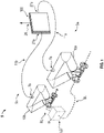
- FIG. 2 shows the dual flow meter system 5 for determining the corrected measured flow rate.
- the dual flow meter system 5 includes the first flow meter 5a and the second flow meter 5b described in the foregoing with reference to FIG. 1 .
- the cases on the meter electronics 100 and first and second meter assembly 10a, 10b are not shown for clarity.
- the first and second meter assembly 10a, 10b respond to mass flow rate and density of a process material.
- the meter electronics 100 is connected to the first and second meter assembly 10a, 10b via a first and second set of leads 11a, 11b to provide density, mass flow rate, and temperature information over the path 26, as well as other information.
- a Coriolis flow meter structure is described although it is apparent to those skilled in the art that the present invention could be practiced with alternative flowmeters.
- the first and second meter assembly 10a, 10b include a pair of parallel conduits 13a, 13a' and 13b, 13b', a first and second drive mechanism 18a, 18b, temperature sensor 19a, 19b, and pair of left and right pick-off sensors 17al, 17ar and 17bl, 17br.
- Each of the pair of conduits 13a, 13a' and 13b, 13b' bend at two symmetrical locations along the conduits 13a, 13a' and 13b, 13b' length and are essentially parallel throughout their length.
- the conduits 13a, 13a' and 13b, 13b' are driven by the drive mechanisms 18a, 18b in opposite directions about their respective bending axes and at what is termed the first out-of-phase bending mode of the flow meter.
- the drive mechanisms 18a, 18b may comprise any one of many arrangements, such as a magnet mounted to the conduits 13a', 13b' and an opposing coil mounted to the conduits 13a, 13b and through which an alternating current is passed for vibrating both conduits 13a, 13a' and 13b, 13b'.
- a suitable drive signal is applied by the meter electronics 100 to the drive mechanism 18a, 18b.
- the first and second flow meter 5a, 5b can be initially calibrated and a flow calibration factor FCF, along with a zero offset ⁇ T 0 , can be generated.
- the flow calibration factor FCF can be multiplied by the time delay ⁇ T measured by the pickoffs minus the zero offset ⁇ T 0 to generate a mass flow rate ⁇ .
- the temperature sensors 19a, 19b are mounted to conduits 13a', 13b' to continuously measure the temperature of the conduits 13a', 13b'.
- the temperature of the conduits 13a', 13b' and hence the voltage appearing across the temperature sensors 19a, 19b for a given current is governed by the temperature of the material passing through the conduits 13a', 13b'.
- the temperature dependent voltages appearing across the temperature sensors 19a, 19b may be used by the meter electronics 100 to compensate for the change in elastic modulus of the conduits 13a', 13b' due to any changes in conduit temperature.
- the temperature sensors 19a, 19b are resistive temperature detectors (RTD). Although the embodiments described herein employ RTD sensors, other temperature sensors may be employed in alternative embodiments, such as thermistors, thermocouples, etc.
- the meter electronics 100 receives the left and right sensor signals from the first and second left and right pick-off sensors 17al, 17ar and 17bl, 17br and the temperature signals from the first and second temperature sensor 19a, 19b via the first and second set of leads 11a, 11b.
- the meter electronics 100 provides a drive signal to the drive mechanism 18a, 18b and vibrates the first and second pair of conduits 13a, 13a' and 13b, 13b'.
- the meter electronics 100 processes the left and right sensor signals and the temperature signals to compute the mass flow rate and the density of the material passing through the first and/or second meter assembly 10a, 10b. This information, along with other information, is applied by meter electronics 100 over path 26 as a signal.
- the dual flow meter system 5 shown in FIGS. 1 and 2 includes only two meter assemblies 10a, 10b, the dual flow meter system 5 may be employed in systems that include more than two meter assemblies.
- a meter electronics may be configured to communicate with three or more meter assemblies.
- the dual flow meter system 5 may be a portion of the meter electronics and two of the three or more meter assemblies.
- FIG. 3 shows a block diagram of the meter electronics 100.
- the meter electronics 100 is communicatively coupled to the first and second meter assembly 10a, 10b.
- the first and second meter assembly 10a, 10b include the first and second left and right pick-off sensors 17al, 17ar and 17bl, 17br, drive mechanism 18a, 18b, and temperature sensor 19a, 19b, which are communicatively coupled to the meter electronics 100 via the first and second set of leads 11a, 11b through a first and second communication channel 112a, 112b and a first and second I/O port 160a, 160b.
- the meter electronics 100 provides a first and second drive signal 14a, 14b via the leads 11a, 11b. More specifically, the meter electronics 100 provides a first drive signal 14a to the first drive mechanism 18a in the first meter assembly 10a. The meter electronics 100 is also configured to provide a second drive signal 14b to the second drive mechanism 18b in the second meter assembly 10b. In addition, a first and second sensor signal 12a, 12b are respectively provided by the first and second meter assembly 10a, 10b. More specifically, in the embodiment shown, the first sensor signal 12a is provided by the first left and right pick-off sensor 17al, 17ar in the first meter assembly 10a.
- the second sensor signal 12b is provided by the second left and right pick-off sensor 17bl, 17br in the second meter assembly 10b.
- the first and second sensor signal 12a, 12b are respectively provided to the meter electronics 100 through the first and second communication channel 112a, 112b.
- the meter electronics 100 includes a processor 110 communicatively coupled to one or more signal processors 120 and one or more memories 130.
- the processor 110 is also communicatively coupled to a user interface 30.
- the processor 110 is communicatively coupled with the host via a communication port 140 over the path 26 and receives electrical power via an electrical power port 150.
- the processor 110 may be a microprocessor although any suitable processor may be employed.
- the processor 110 may be comprised of sub-processors, such as a multi-core processor, serial communication ports, peripheral interfaces (e.g., serial peripheral interface), on-chip memory, I/O ports, and/or the like.
- the processor 110 is configured to perform operations on received and processed signals, such as digitized signals.
- Each of the calibration factors and/or meter assembly zeros may respectively be associated with the first and second flow meter 5a, 5b and/or the first and second meter assembly 10a, 10b.
- the processor 110 may use the calibration factors to process digitized sensor signals received from the one or more signal processors 120.
- the one or more signal processors 120 is shown as being comprised of a first and second encoder/decoder (CODEC) 122, 124 and an analog-to-digital converter (ADC) 126.
- the one or more signal processors 120 may condition analog signals, digitize the conditioned analog signals, and/or provide the digitized signals.
- the first and second CODEC 122, 124 are configured to receive the left and right sensor signal from the first and second left and right pick-off sensors 17al, 17ar and 17bl, 17br.
- the first and second CODEC 122, 124 are also configured to provide the first and second drive signal 14a, 14b to the first and second drive mechanism 18a, 18b.
- more or fewer signal processors may be employed.
- a single CODEC may be employed for the first and second sensor signal 12a, 12b and first and second drive signal 14a, 14b.
- two ADCs may be employed instead of the single ADC 126.
- the one or more memories 130 is comprised of a read-only memory (ROM) 132, random access memory (RAM) 134, and a ferroelectric random-access memory (FRAM) 136.
- ROM read-only memory
- RAM random access memory
- FRAM ferroelectric random-access memory
- the one or more memories 130 may be comprised of more or fewer memories.
- the one or more memories 130 may be comprised of different types of memory (e.g., volatile, non-volatile, etc.).
- a different type of non-volatile memory such as, for example, erasable programmable read only memory (EPROM), or the like, may be employed instead of the FRAM 136.
- EPROM erasable programmable read only memory
- the flow rates through the first and second flow meter 5a, 5b may be the same.
- mass flow rates through the first and second flow meter 5a, 5b should be the same.
- flow rates measured by the first and second flow meter 5a, 5b may not be the same due to zero flow instability.
- the zero flow instability of the first flow meter 5a is greater than the zero flow instability of the second flow meter 5b.
- the first flow meter 5a due to supplying fluid, may have a larger pipe diameter than the second flow meter 5b. Due to the larger pipe diameter, the meter zero of the first flow meter 5a may vary or drift more than the meter zero of the second flow meter 5b. Accordingly, to perform flow rate measurements with the first flow meter 5a, the flow rate measurements by the first flow meter 5a may be corrected by the flow rate measurements of the second flow meter 5b, as the following discusses in more detail.
- the fuel source FS provides fuel to the vehicle V via the supply line SL.
- the fuel may be provided to the vehicle V in liquid form.
- the supply line SL is comprised of the pump P and first flow meter 5a fluidly coupled to the fuel source FS and the vehicle V.
- the first flow meter 5a is configured to measure a flow rate through the supply line SL.
- the flow rate through the supply line SL may be a fuel supply flow rate to the vehicle V.
- the fuel source FS may receive the fuel from the vehicle V via the return line RL and from the supply line SL via the bypass line BL.
- the fuel may be provided to the fuel source FS via the return line RL and bypass line BL in gaseous form.
- the bypass line BL is shown as not including a flow meter.
- the return line RL may be comprised of the second flow meter 5b fluidly coupled to the fuel source FS and the vehicle V.
- the second flow meter 5b may measure the flow rate of the fuel returned to the fuel source FS via the return line RL.
- the valves 420 control the flow paths of the fuel through the fluid control system 400.
- the valves 420 include a first valve 420a fluidly coupled to the first meter assembly, the vehicle V, and a second valve 420b.
- first valve 420a When the first valve 420a is open, the fuel flowing through the supply line SL is provided to the vehicle V.
- first valve 420a When the first valve 420a is closed, the fuel in the supply line SL is not provided to the vehicle V.
- the second valve 420b can also control the flow through the vehicle V.
- first valve 420a if the first valve 420a is open and the second valve 420b is closed, then the fuel will only flow through the vehicle V.
- the fuel flow through the vehicle V may also be controlled by a third valve 420c, which is fluidly coupled to the vehicle V, return line RL, and bypass line BL. If the first valve 420a is closed and the second valve 420b is open, then the fuel will not flow through the vehicle V. Instead, the fuel will flow through the return line RL or the bypass line BL.
- the fuel flow through the return line RL and the bypass line BL may be controlled with the fourth and fifth valve 420d, 420e. If the fourth valve 420d is open and the fifth valve 420e is closed, then the fuel may flow through the return line RL to the fuel source FS. If the fourth valve 420d is closed and the fifth valve 420e is open, then the fuel can flow through the fifth valve 420e in the bypass line BL into the fuel source FS. In other embodiments, the fourth valve 420d, may not be employed. Accordingly, the fuel flow can flow through the return line RL by closing the first, third, and fifth valve 420a, 420c, 420e.
- the flow rates of the fuel through the supply line SL and the return line RL may be measured by the dual flow meter system 5.
- the dual flow meter system 5 is comprised of the first and second flow meter 5a, 5b described in the foregoing.
- the first flow meter 5a is comprised of the meter electronics 100 and the first meter assembly 10a.
- the second flow meter 5b is comprised of the meter electronics 100 and the second meter assembly 10b.
- the meter electronics 100 may be comprised of one or more meter electronics.
- the meter electronics 100 may be comprised of a first meter electronics communicatively coupled to the first meter assembly 10a and a second meter electronics coupled to the second meter assembly 10b. As shown, the meter electronics 100 is communicatively coupled to the first and second meter assembly 10a, 10b via communication lines illustrated as dashed lines. The meter electronics 100 is also communicatively coupled with the system controller 410.
- the system controller 410 may be a host, such as the host communicatively coupled to the meter electronics 100 via the path 26 in FIGS 1-3 .
- the system controller 410 may include, for example, a processor communicatively coupled to a memory, hard drive, etc.
- the system controller 410 is shown as a single integrated assembly although any suitable configuration may be employed.
- the system controller 410 may be a software instance that performs operations in a distributed computing environment.
- the system controller 410 is configured to send and/or receive communications via the communications lines. As shown in FIG. 4 , the system controller 410 can send and/or receive communications to and from the pump P, valves 420, and dual flow meter system 5 to determine a corrected measured flow rate, as the discussion illustrates.
- the system controller 410 and/or meter electronics 100 may employ the following equations (2) - (5) to correct the measured flow rate of the first flow meter 5a.
- a measured flow rate ⁇ a is a flow rate measured by the first flow meter 5a.
- the measured flow rate ⁇ a of the first flow meter 5a may be an uncorrected flow rate.
- the measured flow rate ⁇ a may not yet be corrected by a flow rate measured by the second flow meter 5b.
- the flow rates measured by the first and second flow meter 5a, 5b may be equal.
- a dominant error term in the measured flow rate ⁇ a of the first flow meter 5a may be due to zero flow instability in the first flow meter 5a.
- the measured flow rate ⁇ a of the first flow meter 5a is corrected using the estimated zero flow instability m 0 ⁇ .
- the following equation (5): m ⁇ a ⁇ FCF ⁇ t ⁇ t 0 ⁇ m ⁇ 0 , may be used to obtain a corrected measured flow rate, where:
- Correcting the measured flow rate of the first flow meter 5a extends a range of the first flow meter 5a.
- the range is extended in a turn-down of the first flow meter 5a.
- the turn-down of the first flow meter 5a is a band of low flow rates just above a zero flow where the measurement signal cannot be distinguished from noise, e.g., flows too low to be accurately measured. Correcting the measured flow rate of the first flow meter 5a can also compensate for the impact of the zero flow instability of the first flow meter 5a.
- the ability to use the larger flow meter to measure flow rates, rather than the smaller flow meter, can result in higher flow rates, thereby, for example, reducing fill times of the vehicle V.
- the size ratio between the first and second flow meter 5a, 5b that could result in desirably accurate corrected measured flow rate m ⁇ a ⁇ may be greater than 4, although any suitable ratio may be employed.
- the flow rates measured by the first and second flow meter 5a, 5b may be measured substantially simultaneously.
- the meter electronics 100 is communicatively coupled with the first and second meter assembly 10a, 10b. Accordingly, the flow rates of the fuel flowing through the first and second meter assembly 10a, 10b may be measured as substantially simultaneously.
- each of the two meter electronics may employ a separate clock. The two clocks may have slightly different timing. Accordingly, flow rate measurements made using the two meter electronics, even if made at the same time, may have different rates. Other errors may be associated with using different meter electronics to perform the flow rate measurements.
- two meters may be configured to substantially simultaneously measure the flow rates.
- FIG. 5 shows a method 500 of determining a corrected measured flow rate.
- the method 500 measures a flow rate with a first flow meter.
- the first flow meter may be the first flow meter 5a described in the foregoing with reference to FIG. 4 .
- the method 500 also measures a flow rate with a second flow meter in step 520, which may be the second flow meter 5b described in the foregoing with reference to FIG. 4 .
- the second flow meter is fluidly coupled to the first flow meter in series. For example, with reference to FIG.
- the second flow meter 5b may be fluidly coupled to the first flow meter 5a in series via the second and fourth valve 420b, 420d, which are open while the first, third, and fifth valve 420a, 420c, 420e are closed.
- the fourth valve 420b may not be employed.
- the first and second flow meters 5a, 5b may be fluidly coupled in series only via the second valve 420b.
- the first and second flow meter 5a, 5b may be fluidly coupled in series via the vehicle V when the first, third, and fourth valve 420a, 420c, 420d are open and the second and fifth valve 420b, 420e are closed.
- the flow rate measured by the first flow meter may be measured by the first flow meter 5a shown in FIG. 4 , which is comprised of the first meter assembly 10a and the meter electronics 100.
- the flow rate measured by the first flow meter 5a may be a flow rate of the fuel when fuel is not being provided to the vehicle V.
- the fuel may flow through the first and second flow meter 5a, 5b without flowing through the vehicle V and the bypass line BL.
- the flow rate of the fuel may be measured by the second flow meter 5b, which is in series with the first flow meter 5a.
- the flow rate measured by the second flow meter 5b may be due to the fuel flowing from the vehicle V through the third valve 420c and/or flowing from first flow meter 5a through the second valve 420b.
- the flow rate of the fuel through the second flow meter 5b may be the same as or different than the flow rate through the first flow meter 5a, depending on, for example, which of the valves 420 are open or closed.
- the valves 420 may be open and closed such that the fuel only flows through the supply line SL and return line RL. Due to the fuel only flowing through the supply line SL and the return line RL, the flow rate of the fuel flowing through the first flow meter 5a is substantially the same as the flow rate of the fuel flowing through the second flow meter 5b. Accordingly, the flow rate measured by the first flow meter 5a is
- the measured flow rates of the first and second flow meter 5a, 5b may not be the same.
- the measured flow rate of the first flow meter may be corrected with the measured flow rate of the second flow meter.
- the measured flow rate of the first flow meter 5a may be corrected by the measured flow rate of the second flow meter 5b.
- the measured flow rate of the first flow meter 5a may be corrected by summing the measured flow rate of the second flow meter 5b to the measured flow rate of the first flow meter 5a. Summing the measured flow rates may comprise any suitable operation, including addition and subtraction.
- the measured flow rate of the first flow meter 5a may be subtracted from the measured flow rate of the second flow meter 5b, in accordance with the foregoing equation (4), to determine the estimated zero flow instability m 0 ⁇ of the first flow meter 5a. Accordingly, with reference to the foregoing equation (5), the corrected measured flow rate m ⁇ a ⁇ may be determined using the estimated zero flow instability m 0 ⁇ .
- the method 500 is discussed with reference to FIG. 4 and relationship/equations (3) through (5), alternative systems, relationship, and/or equations may be employed in alternative embodiments.
- the embodiments described above provide the dual flow meter system 5, fluid control system 400, and method 500 to correct a measured flow rate.
- the dual flow meter system 5, fluid control system 400, and method 500 may use the first flow meter 5a to measure the flow rate of, for example, fuel flowing through the supply line SL shown in FIG. 4 .
- the second flow meter 5b may measure the flow rate of the fuel flowing through the return line RL, which is fluidly coupled to the first flow meter 5a in series. Due to the second flow meter 5b being in series with the first flow meter 5a, the fuel flow rates are the same. However, the first flow meter 5a may have zero flow instability. Due to the zero flow instability, the flow rate measured by the first flow meter 5a may be different than the flow rate measured by the second flow meter 5b.
- the measured flow rate of the first flow meter 5a may be corrected by the measured flow rate of the second flow meter 5b.
- the measured flow rate of the first flow meter 5a may be summed with the measured flow rate of the second flow meter 5b. Accordingly, the zero flow instability, which is accurately determined as a difference between the measured flow rates, can be corrected.
Landscapes
- Physics & Mathematics (AREA)
- Fluid Mechanics (AREA)
- General Physics & Mathematics (AREA)
- Engineering & Computer Science (AREA)
- Signal Processing (AREA)
- Measuring Volume Flow (AREA)
Claims (12)
- Verfahren zum Bestimmen einer korrigierten gemessenen Durchflussmenge, wobei das Verfahren Folgendes beinhaltet:Messen einer Durchflussmenge mit einem ersten Durchflussmesser;Messen einer Durchflussmenge mit einem zweiten Durchflussmesser, wobei der zweite Durchflussmesser mit dem ersten Durchflussmesser fluidmäßig in Reihe geschaltet ist; undgekennzeichnet durch Korrigieren der gemessenen Durchflussrate des ersten Durchflussmessers mit einer Differenz zwischen einer zuvor gemessenen Durchflussmenge des ersten Durchflussmessers und einer zuvor gemessenen Durchflussmenge des zweiten Durchflussmessers, die zu einem früheren Zeitpunkt gemessen wurde, als ein Durchfluss durch den ersten Durchflussmesser und den zweiten Durchflussmesser gleich war,wobei die Null-Durchfluss-Instabilität des ersten Durchflussmessers größer ist als eine Null-Durchfluss-Instabilität des zweiten Durchflussmessers, und das Korrigieren der gemessenen Durchflussmenge des ersten Durchflussmessers mit der Differenz zwischen der zuvor gemessenen Durchflussmenge des ersten Durchflussmessers und der zuvor gemessenen Durchflussmenge des zweiten Durchflussmessers einen Messbereich des ersten Durchflussmessers auf Durchflussmengen knapp über einem Null-Durchfluss erweitert, bei denen das Messsignal nicht von Rauschen unterschieden werden kann.
- Verfahren nach Anspruch 1, wobei ein Rohrdurchmesser des ersten Durchflussmessers größer ist als ein Rohrdurchmesser des zweiten Durchflussmessers.
- Verfahren nach einem der vorherigen Ansprüche 1 bis 2, wobei die Durchflussmenge des ersten Durchflussmessers und die Durchflussmenge des zweiten Durchflussmessers im Wesentlichen gleichzeitig gemessen werden.
- Verfahren nach einem der vorherigen Ansprüche 1 bis 2, bei dem die Differenz zwischen der zuvor gemessenen Durchflussrate des ersten Durchflussmessers und der zuvor gemessenen Durchflussrate des zweiten Durchflussmessers in einer Messelektronik gespeichert wird.
- Duales Durchflussmesssystem (5) zum Ermitteln einer korrigierten gemessenen Durchflussmenge, wobei das duale Durchflussmesssystem (5) Folgendes umfasst:einen ersten Durchflussmesser (5a);einen zweiten Durchflussmesser (5b), der mit dem ersten Durchflussmesser (5a) fluidmäßig in Reihe geschaltet ist; undmindestens eine Messelektronik (100), die kommunikativ mit dem ersten Durchflussmesser (5a) und dem zweiten Durchflussmesser (5b) gekoppelt ist, wobei die mindestens eine Messelektronik (100) dadurch gekennzeichnet ist, dass sie zum Korrigieren der gemessenen Durchflussmenge des ersten Durchflussmessers (5a) mit einer Differenz zwischen einer zuvor gemessenen Durchflussmenge des ersten Durchflussmessers (5a) und einer zuvor gemessenen Durchflussmenge des zweiten Durchflussmessers (5b) konfiguriert ist, die zu einem früheren Zeitpunkt gemessen wurde, als ein Durchfluss durch den ersten Durchflussmesser und den zweiten Durchflussmesser gleich war,wobei eine Null-Durchfluss-Instabilität des ersten Durchflussmessers (5a) größer ist als eine Null-Durchfluss-Instabilität des zweiten Durchflussmessers (5b) und das Korrigieren der gemessenen Durchflussmenge des ersten Durchflussmessers mit der Differenz zwischen der zuvor gemessenen Durchflussmenge des ersten Durchflussmessers und der zuvor gemessenen Durchflussmenge des zweiten Durchflussmessers einen Messbereich des ersten Durchflussmessers auf Durchflussmengen knapp über einem Null-Durchfluss erweitert, bei denen das Messsignal nicht von Rauschen unterschieden werden kann.
- Duales Durchflussmesssystem (5) nach Anspruch 5, wobei ein Rohrdurchmesser des ersten Durchflussmessers (5a) größer ist als ein Rohrdurchmesser des zweiten Durchflussmessers (5b).
- Duales Durchflussmesssystem (5) nach einem der vorherigen Ansprüche 5 bis 6, wobei die Durchflussmenge des ersten Durchflussmessers (5a) und die Durchflussmenge des zweiten Durchflussmessers (5b) im Wesentlichen gleichzeitig gemessen werden.
- Duales Durchflussmesssystem (5) nach einem der vorherigen Ansprüche 5 bis 6, wobei die Differenz zwischen der zuvor gemessenen Durchflussmenge des ersten Durchflussmessers und der zuvor gemessenen Durchflussmenge des zweiten Durchflussmessers in der Messelektronik (100) gespeichert ist.
- Fluidsteuersystem (400) zum Bestimmen einer korrigierten gemessenen Durchflussmenge, wobei das Fluidsteuersystem (400) ein duales Durchflussmesssystem (5) nach Anspruch 5 umfasst, wobei das Fluidsteuersystem (400) Folgendes umfasst:eine Vorlaufleitung (SL) mit dem ersten Durchflussmesser (5a);eine Rücklaufleitung (RL) mit dem zweiten Durchflussmesser (5b), der mit dem ersten Durchflussmesser (5a) fluidmäßig in Reihe geschaltet ist; undmindestens eine Systemsteuerung (410), die mit der mindestens einen Messelektronik (100) kommunikativ gekoppelt ist.
- Fluidsteuersystem (400) nach Anspruch 9, wobei ein Rohrdurchmesser des ersten Durchflussmessers (5a) größer ist als ein Rohrdurchmesser des zweiten Durchflussmessers (5b).
- Fluidsteuersystem (400) nach einem der vorherigen Ansprüche 9 bis 10, wobei die Durchflussmenge des ersten Durchflussmessers (5a) und die Durchflussmenge des zweiten Durchflussmessers (5b) im Wesentlichen gleichzeitig gemessen werden.
- Fluidsteuersystem (400) nach einem der vorherigen Ansprüche 9 bis 10, wobei die Differenz zwischen der zuvor gemessenen Durchflussmenge des ersten Durchflussmessers und der zuvor gemessenen Durchflussmenge des zweiten Durchflussmessers in der Messelektronik (100) gespeichert ist.
Applications Claiming Priority (1)
| Application Number | Priority Date | Filing Date | Title |
|---|---|---|---|
| PCT/US2016/019697 WO2017146717A1 (en) | 2016-02-26 | 2016-02-26 | Determining a corrected measured flow rate |
Publications (2)
| Publication Number | Publication Date |
|---|---|
| EP3420323A1 EP3420323A1 (de) | 2019-01-02 |
| EP3420323B1 true EP3420323B1 (de) | 2022-10-19 |
Family
ID=55485374
Family Applications (1)
| Application Number | Title | Priority Date | Filing Date |
|---|---|---|---|
| EP16708576.0A Active EP3420323B1 (de) | 2016-02-26 | 2016-02-26 | Bestimmen eines korrigierten gemessenen durchflusses |
Country Status (5)
| Country | Link |
|---|---|
| US (1) | US11099043B2 (de) |
| EP (1) | EP3420323B1 (de) |
| JP (1) | JP2019506617A (de) |
| CN (1) | CN108700453B (de) |
| WO (1) | WO2017146717A1 (de) |
Families Citing this family (3)
| Publication number | Priority date | Publication date | Assignee | Title |
|---|---|---|---|---|
| US11846533B2 (en) | 2018-10-29 | 2023-12-19 | Endress+Hauser Flowtec Ag | Method for correcting at least one measured value of a Coriolis measuring device and such a Coriolis measuring device |
| KR102059009B1 (ko) * | 2019-02-12 | 2019-12-27 | (주)수인테크 | 바이패스를 이용한 만관/비만관의 미소유량 교정장치 |
| DE102020122583A1 (de) | 2020-08-28 | 2022-03-03 | H2 Mobility Deutschland GmbH & Co. KG | Verfahren und Vorrichtung zum Eichen einer Wasserstofftankstelle |
Citations (1)
| Publication number | Priority date | Publication date | Assignee | Title |
|---|---|---|---|---|
| EP1166056A1 (de) * | 1999-03-26 | 2002-01-02 | Micro Motion Incorporated | Durchflussmesserkalibrationssystem mit statistischer optimierungstechnik |
Family Cites Families (16)
| Publication number | Priority date | Publication date | Assignee | Title |
|---|---|---|---|---|
| US4109524A (en) | 1975-06-30 | 1978-08-29 | S & F Associates | Method and apparatus for mass flow rate measurement |
| USRE31450E (en) | 1977-07-25 | 1983-11-29 | Micro Motion, Inc. | Method and structure for flow measurement |
| JPS5824759Y2 (ja) * | 1978-01-31 | 1983-05-27 | 株式会社東芝 | 流量計の校正装置 |
| JPS5596422A (en) | 1979-01-18 | 1980-07-22 | Oval Eng Co Ltd | Flow rate measuring device |
| US4290298A (en) * | 1980-02-22 | 1981-09-22 | Honeywell Inc. | System for in situ meter testing |
| JPS56130124U (de) * | 1980-03-06 | 1981-10-02 | ||
| US4491025A (en) | 1982-11-03 | 1985-01-01 | Micro Motion, Inc. | Parallel path Coriolis mass flow rate meter |
| US4827430A (en) * | 1987-05-11 | 1989-05-02 | Baxter International Inc. | Flow measurement system |
| DE3722617C1 (de) | 1987-07-09 | 1988-10-06 | Bauknecht Hausgeraete | Elektrisch beheizbare Backauflage |
| JPH10142015A (ja) * | 1996-11-08 | 1998-05-29 | Yazaki Corp | 過渡応答検出装置 |
| US6997033B2 (en) * | 2004-02-03 | 2006-02-14 | Emerson Electric Co. | Flow meter pickoff assembly and flow meter pickoff adjustment method for nulling flow meter zero offset |
| CA2581107C (en) * | 2004-09-27 | 2013-01-08 | Micro Motion, Inc. | In-flow determination of left and right eigenvectors in a coriolis flowmeter |
| SG177731A1 (en) * | 2009-08-12 | 2012-02-28 | Micro Motion Inc | Method and apparatus for determining and compensating for a change in a differential zero offset of a vibrating flow meter |
| CN102713533B (zh) * | 2009-08-12 | 2016-12-28 | 微动公司 | 用于确定振动流量计中的零点偏移的方法和装置 |
| CN103814276B (zh) * | 2011-07-07 | 2017-06-09 | 微动公司 | 确定多仪表流体流动系统的差示流动特性的方法和装置 |
| US20150226597A1 (en) * | 2014-02-12 | 2015-08-13 | Ms. Jennifer Claire Rundle | Method, System and Apparatus for Convenience and Compliance with Environmental Protection Regulations and Occupational Safety Standards during On-Site Fluid Flow Meter Calibration and Verification Procedures |
-
2016
- 2016-02-26 WO PCT/US2016/019697 patent/WO2017146717A1/en active Application Filing
- 2016-02-26 JP JP2018544872A patent/JP2019506617A/ja active Pending
- 2016-02-26 US US16/073,642 patent/US11099043B2/en active Active
- 2016-02-26 EP EP16708576.0A patent/EP3420323B1/de active Active
- 2016-02-26 CN CN201680082595.7A patent/CN108700453B/zh active Active
Patent Citations (1)
| Publication number | Priority date | Publication date | Assignee | Title |
|---|---|---|---|---|
| EP1166056A1 (de) * | 1999-03-26 | 2002-01-02 | Micro Motion Incorporated | Durchflussmesserkalibrationssystem mit statistischer optimierungstechnik |
Also Published As
| Publication number | Publication date |
|---|---|
| CN108700453B (zh) | 2023-11-28 |
| US20190033111A1 (en) | 2019-01-31 |
| EP3420323A1 (de) | 2019-01-02 |
| JP2019506617A (ja) | 2019-03-07 |
| US11099043B2 (en) | 2021-08-24 |
| CN108700453A (zh) | 2018-10-23 |
| WO2017146717A1 (en) | 2017-08-31 |
Similar Documents
| Publication | Publication Date | Title |
|---|---|---|
| US7690240B2 (en) | Flowmeter calibration techniques | |
| CN106471344B (zh) | 用于确定振动流量计中的差分零点偏移的装置和相关方法 | |
| WO2017143579A1 (en) | Limiting a drive signal | |
| EP3420323B1 (de) | Bestimmen eines korrigierten gemessenen durchflusses | |
| EP1558900B1 (de) | Propan messung mittels eines coriolis durchflussmessers | |
| US10598532B2 (en) | Meter electronics for two or more meter assemblies | |
| JP2024029062A (ja) | 補正測定流量の決定 | |
| US10598533B2 (en) | Limiting a current drawn by two or more meter assemblies | |
| CN107131947B (zh) | 确定振动传感器零点 | |
| JP6742429B2 (ja) | 2つ以上のホストとの通信 | |
| JP2020126078A (ja) | 2つ以上のメータアセンブリ用のメータ電子機器 |
Legal Events
| Date | Code | Title | Description |
|---|---|---|---|
| STAA | Information on the status of an ep patent application or granted ep patent |
Free format text: STATUS: THE INTERNATIONAL PUBLICATION HAS BEEN MADE |
|
| PUAI | Public reference made under article 153(3) epc to a published international application that has entered the european phase |
Free format text: ORIGINAL CODE: 0009012 |
|
| STAA | Information on the status of an ep patent application or granted ep patent |
Free format text: STATUS: REQUEST FOR EXAMINATION WAS MADE |
|
| 17P | Request for examination filed |
Effective date: 20180926 |
|
| AK | Designated contracting states |
Kind code of ref document: A1 Designated state(s): AL AT BE BG CH CY CZ DE DK EE ES FI FR GB GR HR HU IE IS IT LI LT LU LV MC MK MT NL NO PL PT RO RS SE SI SK SM TR |
|
| AX | Request for extension of the european patent |
Extension state: BA ME |
|
| DAV | Request for validation of the european patent (deleted) | ||
| DAX | Request for extension of the european patent (deleted) | ||
| STAA | Information on the status of an ep patent application or granted ep patent |
Free format text: STATUS: EXAMINATION IS IN PROGRESS |
|
| 17Q | First examination report despatched |
Effective date: 20200414 |
|
| STAA | Information on the status of an ep patent application or granted ep patent |
Free format text: STATUS: EXAMINATION IS IN PROGRESS |
|
| STAA | Information on the status of an ep patent application or granted ep patent |
Free format text: STATUS: EXAMINATION IS IN PROGRESS |
|
| REG | Reference to a national code |
Ref country code: DE Ref legal event code: R079 Ref document number: 602016075710 Country of ref document: DE Free format text: PREVIOUS MAIN CLASS: G01F0025000000 Ipc: G01F0025100000 |
|
| RIC1 | Information provided on ipc code assigned before grant |
Ipc: G01F 1/84 20060101ALI20220223BHEP Ipc: G01F 25/10 20220101AFI20220223BHEP |
|
| GRAP | Despatch of communication of intention to grant a patent |
Free format text: ORIGINAL CODE: EPIDOSNIGR1 |
|
| STAA | Information on the status of an ep patent application or granted ep patent |
Free format text: STATUS: GRANT OF PATENT IS INTENDED |
|
| INTG | Intention to grant announced |
Effective date: 20220518 |
|
| GRAS | Grant fee paid |
Free format text: ORIGINAL CODE: EPIDOSNIGR3 |
|
| GRAA | (expected) grant |
Free format text: ORIGINAL CODE: 0009210 |
|
| STAA | Information on the status of an ep patent application or granted ep patent |
Free format text: STATUS: THE PATENT HAS BEEN GRANTED |
|
| AK | Designated contracting states |
Kind code of ref document: B1 Designated state(s): AL AT BE BG CH CY CZ DE DK EE ES FI FR GB GR HR HU IE IS IT LI LT LU LV MC MK MT NL NO PL PT RO RS SE SI SK SM TR |
|
| REG | Reference to a national code |
Ref country code: GB Ref legal event code: FG4D |
|
| REG | Reference to a national code |
Ref country code: CH Ref legal event code: EP |
|
| REG | Reference to a national code |
Ref country code: IE Ref legal event code: FG4D |
|
| REG | Reference to a national code |
Ref country code: DE Ref legal event code: R096 Ref document number: 602016075710 Country of ref document: DE |
|
| REG | Reference to a national code |
Ref country code: AT Ref legal event code: REF Ref document number: 1525810 Country of ref document: AT Kind code of ref document: T Effective date: 20221115 |
|
| REG | Reference to a national code |
Ref country code: LT Ref legal event code: MG9D |
|
| REG | Reference to a national code |
Ref country code: NL Ref legal event code: MP Effective date: 20221019 |
|
| REG | Reference to a national code |
Ref country code: AT Ref legal event code: MK05 Ref document number: 1525810 Country of ref document: AT Kind code of ref document: T Effective date: 20221019 |
|
| PG25 | Lapsed in a contracting state [announced via postgrant information from national office to epo] |
Ref country code: NL Free format text: LAPSE BECAUSE OF FAILURE TO SUBMIT A TRANSLATION OF THE DESCRIPTION OR TO PAY THE FEE WITHIN THE PRESCRIBED TIME-LIMIT Effective date: 20221019 |
|
| PG25 | Lapsed in a contracting state [announced via postgrant information from national office to epo] |
Ref country code: SE Free format text: LAPSE BECAUSE OF FAILURE TO SUBMIT A TRANSLATION OF THE DESCRIPTION OR TO PAY THE FEE WITHIN THE PRESCRIBED TIME-LIMIT Effective date: 20221019 Ref country code: PT Free format text: LAPSE BECAUSE OF FAILURE TO SUBMIT A TRANSLATION OF THE DESCRIPTION OR TO PAY THE FEE WITHIN THE PRESCRIBED TIME-LIMIT Effective date: 20230220 Ref country code: NO Free format text: LAPSE BECAUSE OF FAILURE TO SUBMIT A TRANSLATION OF THE DESCRIPTION OR TO PAY THE FEE WITHIN THE PRESCRIBED TIME-LIMIT Effective date: 20230119 Ref country code: LT Free format text: LAPSE BECAUSE OF FAILURE TO SUBMIT A TRANSLATION OF THE DESCRIPTION OR TO PAY THE FEE WITHIN THE PRESCRIBED TIME-LIMIT Effective date: 20221019 Ref country code: FI Free format text: LAPSE BECAUSE OF FAILURE TO SUBMIT A TRANSLATION OF THE DESCRIPTION OR TO PAY THE FEE WITHIN THE PRESCRIBED TIME-LIMIT Effective date: 20221019 Ref country code: ES Free format text: LAPSE BECAUSE OF FAILURE TO SUBMIT A TRANSLATION OF THE DESCRIPTION OR TO PAY THE FEE WITHIN THE PRESCRIBED TIME-LIMIT Effective date: 20221019 Ref country code: AT Free format text: LAPSE BECAUSE OF FAILURE TO SUBMIT A TRANSLATION OF THE DESCRIPTION OR TO PAY THE FEE WITHIN THE PRESCRIBED TIME-LIMIT Effective date: 20221019 |
|
| PG25 | Lapsed in a contracting state [announced via postgrant information from national office to epo] |
Ref country code: RS Free format text: LAPSE BECAUSE OF FAILURE TO SUBMIT A TRANSLATION OF THE DESCRIPTION OR TO PAY THE FEE WITHIN THE PRESCRIBED TIME-LIMIT Effective date: 20221019 Ref country code: PL Free format text: LAPSE BECAUSE OF FAILURE TO SUBMIT A TRANSLATION OF THE DESCRIPTION OR TO PAY THE FEE WITHIN THE PRESCRIBED TIME-LIMIT Effective date: 20221019 Ref country code: LV Free format text: LAPSE BECAUSE OF FAILURE TO SUBMIT A TRANSLATION OF THE DESCRIPTION OR TO PAY THE FEE WITHIN THE PRESCRIBED TIME-LIMIT Effective date: 20221019 Ref country code: IS Free format text: LAPSE BECAUSE OF FAILURE TO SUBMIT A TRANSLATION OF THE DESCRIPTION OR TO PAY THE FEE WITHIN THE PRESCRIBED TIME-LIMIT Effective date: 20230219 Ref country code: HR Free format text: LAPSE BECAUSE OF FAILURE TO SUBMIT A TRANSLATION OF THE DESCRIPTION OR TO PAY THE FEE WITHIN THE PRESCRIBED TIME-LIMIT Effective date: 20221019 Ref country code: GR Free format text: LAPSE BECAUSE OF FAILURE TO SUBMIT A TRANSLATION OF THE DESCRIPTION OR TO PAY THE FEE WITHIN THE PRESCRIBED TIME-LIMIT Effective date: 20230120 |
|
| P01 | Opt-out of the competence of the unified patent court (upc) registered |
Effective date: 20230530 |
|
| REG | Reference to a national code |
Ref country code: DE Ref legal event code: R097 Ref document number: 602016075710 Country of ref document: DE |
|
| PG25 | Lapsed in a contracting state [announced via postgrant information from national office to epo] |
Ref country code: SM Free format text: LAPSE BECAUSE OF FAILURE TO SUBMIT A TRANSLATION OF THE DESCRIPTION OR TO PAY THE FEE WITHIN THE PRESCRIBED TIME-LIMIT Effective date: 20221019 Ref country code: RO Free format text: LAPSE BECAUSE OF FAILURE TO SUBMIT A TRANSLATION OF THE DESCRIPTION OR TO PAY THE FEE WITHIN THE PRESCRIBED TIME-LIMIT Effective date: 20221019 Ref country code: EE Free format text: LAPSE BECAUSE OF FAILURE TO SUBMIT A TRANSLATION OF THE DESCRIPTION OR TO PAY THE FEE WITHIN THE PRESCRIBED TIME-LIMIT Effective date: 20221019 Ref country code: DK Free format text: LAPSE BECAUSE OF FAILURE TO SUBMIT A TRANSLATION OF THE DESCRIPTION OR TO PAY THE FEE WITHIN THE PRESCRIBED TIME-LIMIT Effective date: 20221019 Ref country code: CZ Free format text: LAPSE BECAUSE OF FAILURE TO SUBMIT A TRANSLATION OF THE DESCRIPTION OR TO PAY THE FEE WITHIN THE PRESCRIBED TIME-LIMIT Effective date: 20221019 |
|
| PLBE | No opposition filed within time limit |
Free format text: ORIGINAL CODE: 0009261 |
|
| STAA | Information on the status of an ep patent application or granted ep patent |
Free format text: STATUS: NO OPPOSITION FILED WITHIN TIME LIMIT |
|
| PG25 | Lapsed in a contracting state [announced via postgrant information from national office to epo] |
Ref country code: SK Free format text: LAPSE BECAUSE OF FAILURE TO SUBMIT A TRANSLATION OF THE DESCRIPTION OR TO PAY THE FEE WITHIN THE PRESCRIBED TIME-LIMIT Effective date: 20221019 Ref country code: AL Free format text: LAPSE BECAUSE OF FAILURE TO SUBMIT A TRANSLATION OF THE DESCRIPTION OR TO PAY THE FEE WITHIN THE PRESCRIBED TIME-LIMIT Effective date: 20221019 |
|
| 26N | No opposition filed |
Effective date: 20230720 |
|
| PG25 | Lapsed in a contracting state [announced via postgrant information from national office to epo] |
Ref country code: MC Free format text: LAPSE BECAUSE OF FAILURE TO SUBMIT A TRANSLATION OF THE DESCRIPTION OR TO PAY THE FEE WITHIN THE PRESCRIBED TIME-LIMIT Effective date: 20221019 |
|
| REG | Reference to a national code |
Ref country code: BE Ref legal event code: MM Effective date: 20230228 |
|
| PG25 | Lapsed in a contracting state [announced via postgrant information from national office to epo] |
Ref country code: LU Free format text: LAPSE BECAUSE OF NON-PAYMENT OF DUE FEES Effective date: 20230226 |
|
| PG25 | Lapsed in a contracting state [announced via postgrant information from national office to epo] |
Ref country code: SI Free format text: LAPSE BECAUSE OF FAILURE TO SUBMIT A TRANSLATION OF THE DESCRIPTION OR TO PAY THE FEE WITHIN THE PRESCRIBED TIME-LIMIT Effective date: 20221019 |
|
| REG | Reference to a national code |
Ref country code: IE Ref legal event code: MM4A |
|
| PG25 | Lapsed in a contracting state [announced via postgrant information from national office to epo] |
Ref country code: IE Free format text: LAPSE BECAUSE OF NON-PAYMENT OF DUE FEES Effective date: 20230226 Ref country code: FR Free format text: LAPSE BECAUSE OF NON-PAYMENT OF DUE FEES Effective date: 20230228 |
|
| PG25 | Lapsed in a contracting state [announced via postgrant information from national office to epo] |
Ref country code: BE Free format text: LAPSE BECAUSE OF NON-PAYMENT OF DUE FEES Effective date: 20230228 |
|
| PGFP | Annual fee paid to national office [announced via postgrant information from national office to epo] |
Ref country code: DE Payment date: 20240123 Year of fee payment: 9 Ref country code: GB Payment date: 20240123 Year of fee payment: 9 Ref country code: CH Payment date: 20240301 Year of fee payment: 9 |