US11099043B2 - Determining a corrected measured flow rate - Google Patents
Determining a corrected measured flow rate Download PDFInfo
- Publication number
- US11099043B2 US11099043B2 US16/073,642 US201616073642A US11099043B2 US 11099043 B2 US11099043 B2 US 11099043B2 US 201616073642 A US201616073642 A US 201616073642A US 11099043 B2 US11099043 B2 US 11099043B2
- Authority
- US
- United States
- Prior art keywords
- flow
- meter
- flow meter
- flow rate
- measured
- Prior art date
- Legal status (The legal status is an assumption and is not a legal conclusion. Google has not performed a legal analysis and makes no representation as to the accuracy of the status listed.)
- Active, expires
Links
Images


Classifications
-
- G—PHYSICS
- G01—MEASURING; TESTING
- G01F—MEASURING VOLUME, VOLUME FLOW, MASS FLOW OR LIQUID LEVEL; METERING BY VOLUME
- G01F1/00—Measuring the volume flow or mass flow of fluid or fluent solid material wherein the fluid passes through a meter in a continuous flow
- G01F1/76—Devices for measuring mass flow of a fluid or a fluent solid material
- G01F1/78—Direct mass flowmeters
- G01F1/80—Direct mass flowmeters operating by measuring pressure, force, momentum, or frequency of a fluid flow to which a rotational movement has been imparted
- G01F1/84—Coriolis or gyroscopic mass flowmeters
- G01F1/8409—Coriolis or gyroscopic mass flowmeters constructional details
- G01F1/8436—Coriolis or gyroscopic mass flowmeters constructional details signal processing
-
- G01F25/0007—
-
- G—PHYSICS
- G01—MEASURING; TESTING
- G01F—MEASURING VOLUME, VOLUME FLOW, MASS FLOW OR LIQUID LEVEL; METERING BY VOLUME
- G01F25/00—Testing or calibration of apparatus for measuring volume, volume flow or liquid level or for metering by volume
- G01F25/10—Testing or calibration of apparatus for measuring volume, volume flow or liquid level or for metering by volume of flowmeters
-
- G—PHYSICS
- G01—MEASURING; TESTING
- G01F—MEASURING VOLUME, VOLUME FLOW, MASS FLOW OR LIQUID LEVEL; METERING BY VOLUME
- G01F1/00—Measuring the volume flow or mass flow of fluid or fluent solid material wherein the fluid passes through a meter in a continuous flow
- G01F1/76—Devices for measuring mass flow of a fluid or a fluent solid material
- G01F1/78—Direct mass flowmeters
- G01F1/80—Direct mass flowmeters operating by measuring pressure, force, momentum, or frequency of a fluid flow to which a rotational movement has been imparted
- G01F1/84—Coriolis or gyroscopic mass flowmeters
Definitions
- the embodiments described below relate to flow rate measurements and, more particularly, to determining a corrected measured flow rate.
- Vibrating sensors such as for example, vibrating densitometers and Coriolis flowmeters are generally known, and are used to measure mass flow and other information related to materials flowing through a conduit in the flowmeter.
- Exemplary Coriolis flowmeters are disclosed in U.S. Pat. Nos. 4,109,524, 4,491,025, and Re. 31,450. These flowmeters have meter assemblies with one or more conduits of a straight or curved configuration. Each conduit configuration in a Coriolis mass flowmeter, for example, has a set of natural vibration modes, which may be of simple bending, torsional, or coupled type. Each conduit can be driven to oscillate at a preferred mode.
- a driving force applied to the conduit(s) causes all points along the conduit(s) to oscillate with identical phase or with a small “zero offset”, which is a time delay measured at zero flow.
- the zero offset may be referred to as a meter zero.
- Coriolis forces cause each point along the conduit(s) to have a different phase.
- the phase at the inlet end of the flowmeter lags the phase at the centralized driver position, while the phase at the outlet leads the phase at the centralized driver position.
- Pickoffs on the conduit(s) produce sinusoidal signals representative of the motion of the conduit(s). Signals output from the pickoffs are processed to determine the time delay between the pickoffs. The time delay between the two or more pickoffs is proportional to the mass flow rate of material flowing through the conduit(s).
- a meter electronics connected to the driver generates a drive signal to operate the driver and also to determine a mass flow rate and/or other properties of a process material from signals received from the pickoffs.
- the driver may comprise one of many well-known arrangements; however, a magnet and an opposing drive coil have received great success in the flowmeter industry.
- An alternating current is passed to the drive coil for vibrating the conduit(s) at a desired conduit amplitude and frequency. It is also known in the art to provide the pickoffs as a magnet and coil arrangement very similar to the driver arrangement.
- meter assemblies used in dispensing liquid natural gas (LNG) to LNG vehicles may utilize a first meter assembly to measure fuel pumped from an LNG storage tank to the LNG vehicle.
- a second meter assembly may be used to measure the fuel that is returned to the LNG tank.
- the fuel returned to the LNG tank may have a different flow rate, temperature, state, etc.
- the mass flow rates measured by the first and second flow meter must be the same.
- some flow meters, such as larger flow meters may have meter zeroes that vary or drift. This variation or drift may be referred to as zero flow instability. Due to the zero flow instability, the flow rates measured by the first and second flow meter may be different even though the flow rates are actually the same. Accordingly, there is a need for determining a corrected measured flow rate.
- a method of determining a corrected measured flow rate comprises measuring a flow rate with a first flow meter, measuring a flow rate with a second flow meter, the second flow meter being fluidly coupled to the first flow meter in series, and correcting the measured flow rate of the first flow meter with the measured flow rate of the second flow meter.
- a dual flow meter system for determining a corrected measured flow rate comprises a first flow meter, a second flow meter fluidly coupled in series with the first flow meter, and at least one meter electronics communicatively coupled to the first flow meter and the second flow meter.
- the at least one meter electronics is configured to correct the measured flow rate of the first flow meter with the measured flow rate of the second flow meter.
- the fluid control system comprises a supply line with a first flow meter, a return line with a second flow meter fluidly coupled in series with the first flow meter, and one or more meter electronics communicatively coupled to the first flow meter and the second flow meter, wherein at least one of a system controller communicatively coupled to the one or more meter electronics and the one or more meter electronics is configured to correct the measured flow rate of the first flow meter with the measured flow rate of the second flow meter.
- a method of determining a corrected measured flow rate comprises measuring a flow rate with a first flow meter, measuring a flow rate with a second flow meter, the second flow meter being fluidly coupled to the first flow meter in series, and correcting the measured flow rate of the first flow meter with the measured flow rate of the second flow meter.
- correcting the measured flow rate of the first flow meter comprises summing the measured flow rate of the second flow meter with the measured flow rate of the first flow meter.
- correcting the measured flow rate of the first flow meter comprises correcting the measured flow rate of the first flow meter with an estimated zero flow instability of the first flow meter, the estimated zero flow instability being comprised of a difference between the measured flow rate of the first flow meter and the measured flow rate of the second flow meter.
- the flow rate of the first flow meter and the flow rate of the second flow meter are measured substantially simultaneously.
- the flow rate of the second flow meter is measured prior to the measured flow rate of the first flow meter.
- a dual flow meter system ( 5 ) for determining a corrected measured flow rate comprises a first flow meter ( 5 a ), a second flow meter ( 5 b ) fluidly coupled in series with the first flow meter ( 5 a ), and at least one meter electronics ( 100 ) communicatively coupled to the first flow meter ( 5 a ) and the second flow meter ( 5 b ), the at least one meter electronics ( 100 ) being configured to correct the measured flow rate of the first flow meter ( 5 a ) with the measured flow rate of the second flow meter ( 5 b ).
- the one or more meter electronics ( 100 ) configured to correct the measured flow rate of the first flow meter ( 5 a ) comprises the meter electronics ( 100 ) being configured to sum the measured flow rate of the second flow meter ( 5 b ) with the measured flow rate of the first flow meter ( 5 a ).
- the one or more meter electronics ( 100 ) configured to correct the measured flow rate of the first flow meter ( 5 a ) comprises the one or more meter electronics ( 100 ) configured to correct the measured flow rate of the first flow meter ( 5 a ) with an estimated zero flow instability of the first flow meter ( 5 a ), the estimated zero flow instability being comprised of a difference between the measured flow rate of the first flow meter ( 5 a ) and the measured flow rate of the second flow meter ( 5 b ).
- the flow rate of the first flow meter ( 5 a ) and the flow rate of the second flow meter ( 5 b ) are measured substantially simultaneously.
- the flow rate of the second flow meter ( 5 b ) is measured prior to the measured flow rate of the first flow meter ( 5 a ).
- a fluid control system ( 400 ) for determining a corrected measured flow rate comprises a supply line (SL) with a first flow meter ( 5 a ), a return line (RL) with a second flow meter ( 5 b ) fluidly coupled in series with the first flow meter ( 5 a ), and one or more meter electronics ( 100 ) communicatively coupled to the first flow meter ( 5 a ) and the second flow meter ( 5 b ), wherein at least one of a system controller ( 410 ) is communicatively coupled to the one or more meter electronics ( 100 ) and the one or more meter electronics ( 100 ) is configured to correct the measured flow rate of the first flow meter ( 5 a ) with the measured flow rate of the second flow meter ( 5 b ).
- the at least one of the system controller ( 410 ) and the one or more meter electronics ( 100 ) configured to correct the measured flow rate of the first flow meter ( 5 a ) comprises the at least one of the system controller ( 410 ) and the meter electronics ( 100 ) being configured to sum the measured flow rate of the second flow meter ( 5 b ) with the measured flow rate of the first flow meter ( 5 a ).
- At least one of the system controller ( 410 ) and the one or more meter electronics ( 100 ) configured to correct the measured flow rate of the first flow meter ( 5 a ) comprises the at least one of the system controller ( 410 ) and the one or more meter electronics ( 100 ) configured to correct the measured flow rate of the first flow meter ( 5 a ) with an estimated zero flow instability of the first flow meter ( 5 a ), the estimated zero flow instability being comprised of a difference between the measured flow rate of the first flow meter ( 5 a ) and the measured flow rate of the second flow meter ( 5 b ).
- the flow rate of the first flow meter ( 5 a ) and the flow rate of the second flow meter ( 5 b ) are measured substantially simultaneously.
- the flow rate of the second flow meter ( 5 b ) is measured prior to the measured flow rate of the first flow meter ( 5 a ).
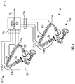
- FIG. 1 shows a dual flow meter system 5 for determining a corrected measured flow rate.
- FIG. 2 shows the dual flow meter system 5 for determining the corrected measured flow rate.
- FIG. 3 shows a block diagram of the meter electronics 100 .
- FIG. 4 shows a fluid control system 400 for determining the corrected measured flow rate.
- FIG. 5 shows a method 500 of determining a corrected measured flow rate.
- FIGS. 1-5 and the following description depict specific examples to teach those skilled in the art how to make and use the best mode of embodiments of determining a corrected measured flow rate.
- some conventional aspects have been simplified or omitted.
- Those skilled in the art will appreciate variations from these examples that fall within the scope of the present description.
- Those skilled in the art will appreciate that the features described below can be combined in various ways to form multiple variations of determining the corrected measured flow rate. As a result, the embodiments described below are not limited to the specific examples described below, but only by the claims and their equivalents.
- Determining the corrected measured flow rate may include measuring a flow rate with a first flow meter and a second flow meter.
- the first and second flow meter may be fluidly coupled in series and, therefore, the same fluid flow is measured by the first and second flow meter.
- the first flow meter may be inaccurate due to zero flow instability of the first flow meter.
- the flow rate measured by the second flow meter may be more accurate than the flow rate measured by the first flow meter.
- the zero flow instability of the first flow meter may be greater than the zero flow instability of the second flow meter.
- the measured flow rate of the first flow meter may be corrected with the measured flow rate of the second flow meter.
- the second flow rate may be summed with the measured flow rate of the first flow meter.
- Summing the measured flow rate may include obtaining an estimated zero flow instability of the first flow meter, which may be a difference between the measured flow rates of the first and second flow meter. Therefore, the corrected measured flow rates of the first flow meter may be more accurate than the measured flow rates.
- FIG. 1 shows a dual flow meter system 5 for determining a corrected measured flow rate.
- the dual flow meter system 5 includes a first flow meter 5 a and a second flow meter 5 b .
- the first and second flow meter 5 a , 5 b are respectively comprised of the meter electronics 100 and the first and second meter assembly 10 a , 10 b.
- the meter electronics 100 is communicatively coupled to the first and second meter assembly 10 a , 10 b via a first and second set of leads 11 a , 11 b .
- the first and second set of leads 11 a , 11 b are coupled (e.g., attached, affixed, etc.) to a first and second communication port 27 a , 27 b on the meter electronics 100 .
- the first and second set of leads 11 a , 11 b are also coupled to the first and second meter assembly 10 a , 10 b via a first and second communication port 7 a , 7 b on the first and second meter assembly 10 a , 10 b .
- the meter electronics 100 is configured to provide information over path 26 to a host.
- the first and second meter assembly 10 a , 10 b are shown with a case that surrounds flow tubes.
- the meter electronics 100 and first and second meter assembly 10 a , 10 b are described in more detail in the following with reference to FIGS. 2 and 3 .
- the first and second flow meter 5 a , 5 b can be used to, for example, calculate a difference in flow rate and/or total flow between a supply line SL and a return line RL.
- the dual flow meter system 5 may be employed in a cryogenic application where fluid is supplied from a tank in liquid state and then returned to the tank in a gaseous state.
- the first meter assembly 10 a may be part of the supply line SL that supplies LNG to an LNG dispenser LD and the second meter assembly 10 b may be part of a return line RL from the LNG dispenser LD.
- the total flow through the second meter assembly 10 b can be subtracted from the total flow through the first meter assembly 10 a to determine the total amount of LNG supplied to the LNG vehicle.
- This exemplary application with the supply and return line SL, RL is shown with dashed lines to illustrate that the dual flow meter system 5 can be employed in other applications.
- Other cryogenic fluids may be employed, such as hydrogen, or the like.
- the calculations can be performed by the meter electronics 100 , which is described in more detail in the following.
- FIG. 2 shows the dual flow meter system 5 for determining the corrected measured flow rate.
- the dual flow meter system 5 includes the first flow meter 5 a and the second flow meter 5 b described in the foregoing with reference to FIG. 1 .
- the cases on the meter electronics 100 and first and second meter assembly 10 a , 10 b are not shown for clarity.
- the first and second meter assembly 10 a , 10 b respond to mass flow rate and density of a process material.
- the meter electronics 100 is connected to the first and second meter assembly 10 a , 10 b via a first and second set of leads 11 a , 11 b to provide density, mass flow rate, and temperature information over the path 26 , as well as other information.
- a Coriolis flow meter structure is described although it is apparent to those skilled in the art that the present invention could be practiced with alternative flowmeters.
- the first and second meter assembly 10 a , 10 b include a pair of parallel conduits 13 a , 13 a ′ and 13 b , 13 b ′, a first and second drive mechanism 18 a , 18 b , temperature sensor 19 a , 19 b , and pair of left and right pick-off sensors 17 a 1 , 17 ar and 17 b 1 , 17 br .
- Each of the pair of conduits 13 a , 13 a ′ and 13 b , 13 b ′ bend at two symmetrical locations along the conduits 13 a , 13 a ′ and 13 b , 13 b ′ length and are essentially parallel throughout their length.
- the conduits 13 a , 13 a ′ and 13 b , 13 b ′ are driven by the drive mechanisms 18 a , 18 b in opposite directions about their respective bending axes and at what is termed the first out-of-phase bending mode of the flow meter.
- the drive mechanisms 18 a , 18 b may comprise any one of many arrangements, such as a magnet mounted to the conduits 13 a ′, 13 b ′ and an opposing coil mounted to the conduits 13 a , 13 b and through which an alternating current is passed for vibrating both conduits 13 a , 13 a ′ and 13 b , 13 b ′.
- a suitable drive signal is applied by the meter electronics 100 to the drive mechanism 18 a , 18 b.
- the first and second flow meter 5 a , 5 b can be initially calibrated and a flow calibration factor FCF, along with a zero offset ⁇ T 0 , can be generated.
- the flow calibration factor FCF can be multiplied by the time delay ⁇ T measured by the pickoffs minus the zero offset ⁇ T 0 to generate a mass flow rate ⁇ dot over (m) ⁇ .
- the temperature sensors 19 a , 19 b are mounted to conduits 13 a ′, 13 b ′ to continuously measure the temperature of the conduits 13 a ′, 13 b ′.
- the temperature of the conduits 13 a ′, 13 b ′ and hence the voltage appearing across the temperature sensors 19 a , 19 b for a given current is governed by the temperature of the material passing through the conduits 13 a ′, 13 b ′.
- the temperature dependent voltages appearing across the temperature sensors 19 a , 19 b may be used by the meter electronics 100 to compensate for the change in elastic modulus of the conduits 13 a ′, 13 b ′ due to any changes in conduit temperature.
- the temperature sensors 19 a , 19 b are resistive temperature detectors (RTD).
- RTD resistive temperature detectors
- the meter electronics 100 receives the left and right sensor signals from the first and second left and right pick-off sensors 17 a 1 , 17 ar and 17 b 1 , 17 br and the temperature signals from the first and second temperature sensor 19 a , 19 b via the first and second set of leads 11 a , 11 b .
- the meter electronics 100 provides a drive signal to the drive mechanism 18 a , 18 b and vibrates the first and second pair of conduits 13 a , 13 a ′ and 13 b , 13 b ′.
- the meter electronics 100 processes the left and right sensor signals and the temperature signals to compute the mass flow rate and the density of the material passing through the first and/or second meter assembly 10 a , 10 b . This information, along with other information, is applied by meter electronics 100 over path 26 as a signal.
- the dual flow meter system 5 shown in FIGS. 1 and 2 includes only two meter assemblies 10 a , 10 b
- the dual flow meter system 5 may be employed in systems that include more than two meter assemblies.
- a meter electronics may be configured to communicate with three or more meter assemblies.
- the dual flow meter system 5 may be a portion of the meter electronics and two of the three or more meter assemblies.
- FIG. 3 shows a block diagram of the meter electronics 100 .
- the meter electronics 100 is communicatively coupled to the first and second meter assembly 10 a , 10 b . As described in the foregoing with reference to FIG.
- the first and second meter assembly 10 a , 10 b include the first and second left and right pick-off sensors 17 a 1 , 17 ar and 17 b 1 , 17 br , drive mechanism 18 a , 18 b , and temperature sensor 19 a , 19 b , which are communicatively coupled to the meter electronics 100 via the first and second set of leads 11 a , 11 b through a first and second communication channel 112 a , 112 b and a first and second I/O port 160 a , 160 b.
- the meter electronics 100 provides a first and second drive signal 14 a , 14 b via the leads 11 a , 11 b . More specifically, the meter electronics 100 provides a first drive signal 14 a to the first drive mechanism 18 a in the first meter assembly 10 a . The meter electronics 100 is also configured to provide a second drive signal 14 b to the second drive mechanism 18 b in the second meter assembly 10 b . In addition, a first and second sensor signal 12 a , 12 b are respectively provided by the first and second meter assembly 10 a , 10 b . More specifically, in the embodiment shown, the first sensor signal 12 a is provided by the first left and right pick-off sensor 17 a 1 , 17 ar in the first meter assembly 10 a .
- the second sensor signal 12 b is provided by the second left and right pick-off sensor 17 b 1 , 17 br in the second meter assembly 10 b .
- the first and second sensor signal 12 a , 12 b are respectively provided to the meter electronics 100 through the first and second communication channel 112 a , 112 b.
- the meter electronics 100 includes a processor 110 communicatively coupled to one or more signal processors 120 and one or more memories 130 .
- the processor 110 is also communicatively coupled to a user interface 30 .
- the processor 110 is communicatively coupled with the host via a communication port 140 over the path 26 and receives electrical power via an electrical power port 150 .
- the processor 110 may be a microprocessor although any suitable processor may be employed.
- the processor 110 may be comprised of sub-processors, such as a multi-core processor, serial communication ports, peripheral interfaces (e.g., serial peripheral interface), on-chip memory, I/O ports, and/or the like.
- the processor 110 is configured to perform operations on received and processed signals, such as digitized signals.
- the processor 110 may receive digitized sensor signals from the one or more signal processors 120 .
- the processor 110 is also configured to provide information, such as a phase difference, a property of a fluid in the first or second meter assembly 10 a , 10 b , or the like.
- the processor 110 may provide the information to the host through the communication port 140 .
- the processor 110 may also be configured to communicate with the one or more memories 130 to receive and/or store information in the one or more memories 130 .
- the processor 110 may receive calibration factors and/or meter assembly zeros (e.g., phase difference when there is zero flow) from the one or more memories 130 .
- Each of the calibration factors and/or meter assembly zeros may respectively be associated with the first and second flow meter 5 a , 5 b and/or the first and second meter assembly 10 a , 10 b .
- the processor 110 may use the calibration factors to process digitized sensor signals received from the one or more signal processors 120 .
- the one or more signal processors 120 is shown as being comprised of a first and second encoder/decoder (CODEC) 122 , 124 and an analog-to-digital converter (ADC) 126 .
- the one or more signal processors 120 may condition analog signals, digitize the conditioned analog signals, and/or provide the digitized signals.
- the first and second CODEC 122 , 124 are configured to receive the left and right sensor signal from the first and second left and right pick-off sensors 17 a 1 , 17 ar and 17 b 1 , 17 br .
- the first and second CODEC 122 , 124 are also configured to provide the first and second drive signal 14 a , 14 b to the first and second drive mechanism 18 a , 18 b .
- more or fewer signal processors may be employed.
- a single CODEC may be employed for the first and second sensor signal 12 a , 12 b and first and second drive signal 14 a , 14 b .
- two ADCs may be employed instead of the single ADC 126 .
- the one or more memories 130 is comprised of a read-only memory (ROM) 132 , random access memory (RAM) 134 , and a ferroelectric random-access memory (FRAM) 136 .
- the one or more memories 130 may be comprised of more or fewer memories.
- the one or more memories 130 may be comprised of different types of memory (e.g., volatile, non-volatile, etc.).
- a different type of non-volatile memory such as, for example, erasable programmable read only memory (EPROM), or the like, may be employed instead of the FRAM 136 .
- EPROM erasable programmable read only memory
- the dual flow meter system 5 shown in FIG. 3 includes only two meter assemblies 10 a , 10 b
- the dual flow meter system 5 may be employed in systems that include more than two meter assemblies.
- a meter electronics may be configured to communicate with three or more meter assemblies.
- the dual flow meter system 5 may be a portion of the meter electronics and two of the three or more meter assemblies.
- the flow rates through the first and second flow meter 5 a , 5 b may be the same.
- mass flow rates through the first and second flow meter 5 a , 5 b should be the same.
- flow rates measured by the first and second flow meter 5 a , 5 b may not be the same due to zero flow instability.
- the zero flow instability of the first flow meter 5 a may be greater than the zero flow instability of the second flow meter 5 b.
- the first flow meter 5 a due to supplying fluid, may have a larger pipe diameter than the second flow meter 5 b . Due to the larger pipe diameter, the meter zero of the first flow meter 5 a may vary or drift more than the meter zero of the second flow meter 5 b . Accordingly, to perform flow rate measurements with the first flow meter 5 a , the flow rate measurements by the first flow meter 5 a may be corrected by the flow rate measurements of the second flow meter 5 b , as the following discusses in more detail.
- FIG. 4 shows a fluid control system 400 for determining the corrected measured flow rate.
- the fluid control system 400 is a fuel control system that includes a fuel source FS fluidly coupled to a vehicle V.
- the fuel source FS is fluidly coupled to the vehicle V via a supply line SL, return line RL, and a bypass line BL.
- the fluid control system 400 includes the dual flow meter system 5 described in the foregoing.
- the fluid control system 400 also includes a system controller 410 that is communicatively coupled to valves 420 via communication lines illustrated as dashed lines.
- the system controller 410 is also communicatively coupled to the dual flow meter system 5 .
- the fuel source FS provides fuel to the vehicle V via the supply line SL.
- the fuel may be provided to the vehicle V in liquid form.
- the supply line SL is comprised of the pump P and first flow meter 5 a fluidly coupled to the fuel source FS and the vehicle V.
- the first flow meter 5 a is configured to measure a flow rate through the supply line SL.
- the flow rate through the supply line SL may be a fuel supply flow rate to the vehicle V.
- the fuel source FS may receive the fuel from the vehicle V via the return line RL and from the supply line SL via the bypass line BL.
- the fuel may be provided to the fuel source FS via the return line RL and bypass line BL in gaseous form.
- the bypass line BL is shown as not including a flow meter.
- the return line RL may be comprised of the second flow meter 5 b fluidly coupled to the fuel source FS and the vehicle V.
- the second flow meter 5 b may measure the flow rate of the fuel returned to the fuel source FS via the return line RL.
- the valves 420 control the flow paths of the fuel through the fluid control system 400 .
- the valves 420 include a first valve 420 a fluidly coupled to the first meter assembly, the vehicle V, and a second valve 420 b .
- first valve 420 a When the first valve 420 a is open, the fuel flowing through the supply line SL is provided to the vehicle V.
- first valve 420 a When the first valve 420 a is closed, the fuel in the supply line SL is not provided to the vehicle V.
- the second valve 420 b can also control the flow through the vehicle V.
- first valve 420 a is open and the second valve 420 b is closed, then the fuel will only flow through the vehicle V.
- the fuel flow through the vehicle V may also be controlled by a third valve 420 c , which is fluidly coupled to the vehicle V, return line RL, and bypass line BL. If the first valve 420 a is closed and the second valve 420 b is open, then the fuel will not flow through the vehicle V. Instead, the fuel will flow through the return line RL or the bypass line BL.
- the fuel flow through the return line RL and the bypass line BL may be controlled with the fourth and fifth valve 420 d , 420 e . If the fourth valve 420 d is open and the fifth valve 420 e is closed, then the fuel may flow through the return line RL to the fuel source FS. If the fourth valve 420 d is closed and the fifth valve 420 e is open, then the fuel can flow through the fifth valve 420 e in the bypass line BL into the fuel source FS. In other embodiments, the fourth valve 420 d , may not be employed. Accordingly, the fuel flow can flow through the return line RL by closing the first, third, and fifth valve 420 a , 420 c , 420 e.
- the flow rates of the fuel through the supply line SL and the return line RL may be measured by the dual flow meter system 5 .
- the dual flow meter system 5 is comprised of the first and second flow meter 5 a , 5 b described in the foregoing.
- the first flow meter 5 a is comprised of the meter electronics 100 and the first meter assembly 10 a .
- the second flow meter 5 b is comprised of the meter electronics 100 and the second meter assembly 10 b .
- the meter electronics 100 may be comprised of one or more meter electronics.
- the meter electronics 100 may be comprised of a first meter electronics communicatively coupled to the first meter assembly 10 a and a second meter electronics coupled to the second meter assembly 10 b .
- the meter electronics 100 is communicatively coupled to the first and second meter assembly 10 a , 10 b via communication lines illustrated as dashed lines.
- the meter electronics 100 is also communicatively coupled with the system controller 410 .
- the system controller 410 may be a host, such as the host communicatively coupled to the meter electronics 100 via the path 26 in FIGS. 1-3 .
- the system controller 410 may include, for example, a processor communicatively coupled to a memory, hard drive, etc.
- the system controller 410 is shown as a single integrated assembly although any suitable configuration may be employed.
- the system controller 410 may be a software instance that performs operations in a distributed computing environment.
- the system controller 410 is configured to send and/or receive communications via the communications lines. As shown in FIG. 4 , the system controller 410 can send and/or receive communications to and from the pump P, valves 420 , and dual flow meter system 5 to determine a corrected measured flow rate, as the discussion illustrates.
- the system controller 410 and/or meter electronics 100 may employ the following equations (2)-(5) to correct the measured flow rate of the first flow meter 5 a .
- the measured flow rate ⁇ dot over (m) ⁇ a of the first flow meter 5 a may be an uncorrected flow rate.
- the measured flow rate ⁇ dot over (m) ⁇ a is determined using the flow calibration factors FCF and meter zero t 0 (also referred to as zero offset, etc.) of the first meter assembly 10 a , the measured flow rate ⁇ dot over (m) ⁇ a may not yet be corrected by a flow rate measured by the second flow meter 5 b.
- the flow rates measured by the first and second flow meter 5 a , 5 b may be equal.
- the measured flow rates of the first and second flow meter 5 a , 5 b may be equal, resulting in the following relationship (3): ⁇ dot over (m) ⁇ b ⁇ dot over (m) ⁇ b .
- ⁇ dot over (m) ⁇ a is the measured flow rate of the first flow meter 5 a ;
- ⁇ dot over (m) ⁇ b is the measured flow rate of the second flow meter 5 b.
- a dominant error term in the measured flow rate ⁇ dot over (m) ⁇ a of the first flow meter 5 a may be due to zero flow instability in the first flow meter 5 a .
- the measured flow rate ⁇ dot over (m) ⁇ a of the first flow meter 5 a may be corrected using the estimated zero flow instability .
- the following equation (5): FCF( ⁇ t ⁇ t 0 ) ⁇ ⁇ circumflex over (m) ⁇ 0 , (5) may be used to obtain a corrected measured flow rate, where:
- FCF is the flow calibration factor
- t 0 is the meter zero
- Correcting the measured flow rate of the first flow meter 5 a can, for example, extend a range of the first flow meter 5 a .
- the range may be extended in a turn-down of the first flow meter 5 a .
- the turn-down of the first flow meter 5 a may be a band of low flow rates just above a zero flow where the measurement signal cannot be distinguished from noise, e.g., flows too low to be accurately measured.
- Correcting the measured flow rate of the first flow meter 5 a can also compensate for the impact of the zero flow instability of the first flow meter 5 a .
- the ability to use the larger flow meter to measure flow rates, rather than the smaller flow meter, can result in higher flow rates, thereby, for example, reducing fill times of the vehicle V.
- the size ratio between the first and second flow meter 5 a , 5 b that could result in desirably accurate corrected measured flow rate may be greater than 4, although any suitable ratio may be employed.
- the flow rates measured by the first and second flow meter 5 a , 5 b may be measured substantially simultaneously.
- the meter electronics 100 is communicatively coupled with the first and second meter assembly 10 a , 10 b . Accordingly, the flow rates of the fuel flowing through the first and second meter assembly 10 a , 10 b may be measured as substantially simultaneously.
- each of the two meter electronics may employ a separate clock. The two clocks may have slightly different timing. Accordingly, flow rate measurements made using the two meter electronics, even if made at the same time, may have different rates. Other errors may be associated with using different meter electronics to perform the flow rate measurements.
- two meters may be configured to substantially simultaneously measure the flow rates.
- the estimated zero flow instability may accurately characterize zero flow instability of the first flow meter 5 a .
- the estimated zero flow instability may be employed to correct a measured flow rate, as the following discussion illustrates.
- FIG. 5 shows a method 500 of determining a corrected measured flow rate.
- the method 500 measures a flow rate with a first flow meter.
- the first flow meter may be the first flow meter 5 a described in the foregoing with reference to FIG. 4 .
- the method 500 also measures a flow rate with a second flow meter in step 520 , which may be the second flow meter 5 b described in the foregoing with reference to FIG. 4 .
- the second flow meter may be fluidly coupled to the first flow meter in series. For example, with reference to FIG.
- the second flow meter 5 b may be fluidly coupled to the first flow meter 5 a in series via the second and fourth valve 420 b , 420 d , which are open while the first, third, and fifth valve 420 a , 420 c , 420 e are closed.
- the fourth valve 420 b may not be employed. Accordingly, the first and second flow meters 5 a , 5 b may be fluidly coupled in series only via the second valve 420 b .
- first and second flow meter 5 a , 5 b may be fluidly coupled in series via the vehicle V when the first, third, and fourth valve 420 a , 420 c , 420 d are open and the second and fifth valve 420 b , 420 e are closed.
- the flow rate measured by the first flow meter may be measured by the first flow meter 5 a shown in FIG. 4 , which is comprised of the first meter assembly 10 a and the meter electronics 100 .
- the flow rate measured by the first flow meter 5 a may be a flow rate of the fuel when fuel is not being provided to the vehicle V.
- the fuel may flow through the first and second flow meter 5 a , 5 b without flowing through the vehicle V and the bypass line BL.
- the flow rate of the fuel may be measured by the second flow meter 5 b , which may be in series with the first flow meter 5 a .
- the flow rate measured by the second flow meter 5 b may be due to the fuel flowing from the vehicle V through the third valve 420 c and/or flowing from first flow meter 5 a through the second valve 420 b .
- the flow rate of the fuel through the second flow meter 5 b may be the same as or different than the flow rate through the first flow meter 5 a , depending on, for example, which of the valves 420 are open or closed.
- the valves 420 may be open and closed such that the fuel only flows through the supply line SL and return line RL. Due to the fuel only flowing through the supply line SL and the return line RL, the flow rate of the fuel flowing through the first flow meter 5 a is substantially the same as the flow rate of the fuel flowing through the second flow meter 5 b . Accordingly, the flow rate measured by the first flow meter 5 a may be the same as the flow rate measured by the second flow meter 5 b . However, due to zero flow instability of one of the first and second flow meter 5 a , 5 b , the measured flow rates of the first and second flow meter 5 a , 5 b may not be the same.
- the measured flow rate of the first flow meter may be corrected with the measured flow rate of the second flow meter.
- the measured flow rate of the first flow meter 5 a may be corrected by the measured flow rate of the second flow meter 5 b .
- the measured flow rate of the first flow meter 5 a may be corrected by summing the measured flow rate of the second flow meter 5 b to the measured flow rate of the first flow meter 5 a . Summing the measured flow rates may comprise any suitable operation, including addition and subtraction.
- the measured flow rate of the first flow meter 5 a may be subtracted from the measured flow rate of the second flow meter 5 b , in accordance with the foregoing equation (4), to determine the estimated zero flow instability of the first flow meter 5 a .
- the corrected measured flow rate may be determined using the estimated zero flow instability .
- the measured flow rates of the first and second flow meter 5 a , 5 b are described as being performed substantially simultaneously. However, in alternative embodiments, the measurements may be performed at different times. For example, the estimated zero flow instability could be determined with flow rates that are measured substantially simultaneously, stored in the meter electronics 100 , and used to correct subsequent measured flow rates of the first flow meter 5 a .
- the foregoing discusses determining the corrected measured flow rates in the fluid control system 400 , which, as shown in FIG. 4 , is a fuel control system that can dispense LNG
- measured flow rates may be corrected in alternative systems.
- the alternative systems can dispense marine fuels or the like.
- the alternative systems may also be employed in proving, custody transfer, or efficiency applications. Other applications and configurations of the alternative systems may be employed.
- the embodiments described above provide the dual flow meter system 5 , fluid control system 400 , and method 500 to correct a measured flow rate.
- the dual flow meter system 5 , fluid control system 400 , and method 500 may use the first flow meter 5 a to measure the flow rate of, for example, fuel flowing through the supply line SL shown in FIG. 4 .
- the second flow meter 5 b may measure the flow rate of the fuel flowing through the return line RL, which may be fluidly coupled to the first flow meter 5 a in series. Due to, for example, the second flow meter 5 b being in series with the first flow meter 5 a , the fuel flow rates may be the same. However, the first flow meter 5 a may have zero flow instability. Due to the zero flow instability, the flow rate measured by the first flow meter 5 a may be different than the flow rate measured by the second flow meter 5 b.
- the measured flow rate of the first flow meter 5 a may be corrected by the measured flow rate of the second flow meter 5 b .
- the measured flow rate of the first flow meter 5 a may be summed with the measured flow rate of the second flow meter 5 b . Accordingly, the zero flow instability, which may be accurately determined as a difference between the measured flow rates, can be corrected.
- the dual flow meter system 5 may be advantageous when the flow rate of the first flow meter 5 a and the flow rate of the second flow meter 5 b are measured substantially simultaneously.
- the fluid flow rate of, for example, fuel may be the same through both the first and second flow meter 5 a , 5 b .
- utilizing the meter electronics 100 communicatively coupled to the first and second meter assembly 10 a , 10 b may ensure that the measurements are obtained at substantially the same time such that the measured flow rates may not include, for example, errors associated with timing issues between different meter electronics.
Abstract
Description
{dot over (m)}=FCF(ΔT measured −ΔT 0) (1)
Where:
{dot over (m)} a=FCF(Δt−t 0), (2)
a measured flow rate {dot over (m)}a, is a flow rate measured by the
{dot over (m)} b
{circumflex over (m)} 0 ={dot over (m)} b −{dot over (m)} a, (4)
Where:
may be used to obtain a corrected measured flow rate, where:
Claims (12)
Applications Claiming Priority (1)
| Application Number | Priority Date | Filing Date | Title |
|---|---|---|---|
| PCT/US2016/019697 WO2017146717A1 (en) | 2016-02-26 | 2016-02-26 | Determining a corrected measured flow rate |
Publications (2)
| Publication Number | Publication Date |
|---|---|
| US20190033111A1 US20190033111A1 (en) | 2019-01-31 |
| US11099043B2 true US11099043B2 (en) | 2021-08-24 |
Family
ID=55485374
Family Applications (1)
| Application Number | Title | Priority Date | Filing Date |
|---|---|---|---|
| US16/073,642 Active 2036-09-01 US11099043B2 (en) | 2016-02-26 | 2016-02-26 | Determining a corrected measured flow rate |
Country Status (5)
| Country | Link |
|---|---|
| US (1) | US11099043B2 (en) |
| EP (1) | EP3420323B1 (en) |
| JP (1) | JP2019506617A (en) |
| CN (1) | CN108700453B (en) |
| WO (1) | WO2017146717A1 (en) |
Families Citing this family (3)
| Publication number | Priority date | Publication date | Assignee | Title |
|---|---|---|---|---|
| WO2020088837A1 (en) | 2018-10-29 | 2020-05-07 | Endress+Hauser Flowtec Ag | Method for correcting at least one measured value of a coriolis measuring device and such a coriolis measuring device |
| KR102059009B1 (en) * | 2019-02-12 | 2019-12-27 | (주)수인테크 | Apparatus for calibrating a flowmeter at microflow in full pipe and non-full pipe using bypass |
| DE102020122583A1 (en) | 2020-08-28 | 2022-03-03 | H2 Mobility Deutschland GmbH & Co. KG | Method and device for calibrating a hydrogen filling station |
Citations (5)
| Publication number | Priority date | Publication date | Assignee | Title |
|---|---|---|---|---|
| JPS5596422A (en) | 1979-01-18 | 1980-07-22 | Oval Eng Co Ltd | Flow rate measuring device |
| EP0298567A1 (en) | 1987-07-09 | 1989-01-11 | Bauknecht Hausgeräte GmbH | Electrically heated food support |
| US20120125123A1 (en) | 2009-08-12 | 2012-05-24 | Micro Motion, Inc. | Method and apparatus for determining and compensating for a change in a differential zero offset of a vibrating flow meter |
| US20140123727A1 (en) | 2011-07-07 | 2014-05-08 | Micro Motion, Inc. | Method and apparatus for determining differential flow characteristics of a multiple meter fluid flow system |
| US20150226597A1 (en) * | 2014-02-12 | 2015-08-13 | Ms. Jennifer Claire Rundle | Method, System and Apparatus for Convenience and Compliance with Environmental Protection Regulations and Occupational Safety Standards during On-Site Fluid Flow Meter Calibration and Verification Procedures |
Family Cites Families (12)
| Publication number | Priority date | Publication date | Assignee | Title |
|---|---|---|---|---|
| US4109524A (en) | 1975-06-30 | 1978-08-29 | S & F Associates | Method and apparatus for mass flow rate measurement |
| USRE31450E (en) | 1977-07-25 | 1983-11-29 | Micro Motion, Inc. | Method and structure for flow measurement |
| JPS5824759Y2 (en) * | 1978-01-31 | 1983-05-27 | 株式会社東芝 | Flow meter calibration device |
| US4290298A (en) * | 1980-02-22 | 1981-09-22 | Honeywell Inc. | System for in situ meter testing |
| JPS56130124U (en) * | 1980-03-06 | 1981-10-02 | ||
| US4491025A (en) | 1982-11-03 | 1985-01-01 | Micro Motion, Inc. | Parallel path Coriolis mass flow rate meter |
| US4827430A (en) * | 1987-05-11 | 1989-05-02 | Baxter International Inc. | Flow measurement system |
| JPH10142015A (en) * | 1996-11-08 | 1998-05-29 | Yazaki Corp | Transient-response detecting apparatus |
| US6360579B1 (en) * | 1999-03-26 | 2002-03-26 | Micro Motion, Inc. | Flowmeter calibration system with statistical optimization technique |
| US6997033B2 (en) * | 2004-02-03 | 2006-02-14 | Emerson Electric Co. | Flow meter pickoff assembly and flow meter pickoff adjustment method for nulling flow meter zero offset |
| CN100458377C (en) * | 2004-09-27 | 2009-02-04 | 微动公司 | In-flow determination of left and right eigenvectors in a Coriolis flowmeter |
| CN102713533B (en) * | 2009-08-12 | 2016-12-28 | 微动公司 | For the method and apparatus determining the zero migration in vibrating flowmeter |
-
2016
- 2016-02-26 WO PCT/US2016/019697 patent/WO2017146717A1/en active Application Filing
- 2016-02-26 CN CN201680082595.7A patent/CN108700453B/en active Active
- 2016-02-26 JP JP2018544872A patent/JP2019506617A/en active Pending
- 2016-02-26 EP EP16708576.0A patent/EP3420323B1/en active Active
- 2016-02-26 US US16/073,642 patent/US11099043B2/en active Active
Patent Citations (5)
| Publication number | Priority date | Publication date | Assignee | Title |
|---|---|---|---|---|
| JPS5596422A (en) | 1979-01-18 | 1980-07-22 | Oval Eng Co Ltd | Flow rate measuring device |
| EP0298567A1 (en) | 1987-07-09 | 1989-01-11 | Bauknecht Hausgeräte GmbH | Electrically heated food support |
| US20120125123A1 (en) | 2009-08-12 | 2012-05-24 | Micro Motion, Inc. | Method and apparatus for determining and compensating for a change in a differential zero offset of a vibrating flow meter |
| US20140123727A1 (en) | 2011-07-07 | 2014-05-08 | Micro Motion, Inc. | Method and apparatus for determining differential flow characteristics of a multiple meter fluid flow system |
| US20150226597A1 (en) * | 2014-02-12 | 2015-08-13 | Ms. Jennifer Claire Rundle | Method, System and Apparatus for Convenience and Compliance with Environmental Protection Regulations and Occupational Safety Standards during On-Site Fluid Flow Meter Calibration and Verification Procedures |
Also Published As
| Publication number | Publication date |
|---|---|
| JP2019506617A (en) | 2019-03-07 |
| EP3420323A1 (en) | 2019-01-02 |
| CN108700453B (en) | 2023-11-28 |
| US20190033111A1 (en) | 2019-01-31 |
| WO2017146717A1 (en) | 2017-08-31 |
| CN108700453A (en) | 2018-10-23 |
| EP3420323B1 (en) | 2022-10-19 |
Similar Documents
| Publication | Publication Date | Title |
|---|---|---|
| CN106471344B (en) | Apparatus and associated method for determining differential zero offset in a vibrating flow meter | |
| US10591334B2 (en) | Limiting a drive signal | |
| US11099043B2 (en) | Determining a corrected measured flow rate | |
| CN106662478B (en) | Differential flow meter tool | |
| EP1558900B1 (en) | Propane measurement using a coriolis flowmeter | |
| US10598532B2 (en) | Meter electronics for two or more meter assemblies | |
| JP2024029062A (en) | Determining the corrected measured flow rate | |
| US10598533B2 (en) | Limiting a current drawn by two or more meter assemblies | |
| JP7093805B2 (en) | Meter electronics for two or more meter assemblies | |
| CN205991835U (en) | Meter electronics and double vibrating sensor system | |
| CN107131947B (en) | Determining a vibration sensor zero point | |
| US11221247B2 (en) | Communicating with two or more hosts | |
| WO2023200431A1 (en) | A pressure compensation of a fluid flow parameter |
Legal Events
| Date | Code | Title | Description |
|---|---|---|---|
| AS | Assignment |
Owner name: MICRO MOTION, INC., COLORADO Free format text: ASSIGNMENT OF ASSIGNORS INTEREST;ASSIGNORS:MAGINNIS, RICHARD L.;STANDIFORD, DEAN M.;SIGNING DATES FROM 20160208 TO 20160209;REEL/FRAME:046487/0300 |
|
| FEPP | Fee payment procedure |
Free format text: ENTITY STATUS SET TO UNDISCOUNTED (ORIGINAL EVENT CODE: BIG.); ENTITY STATUS OF PATENT OWNER: LARGE ENTITY |
|
| STPP | Information on status: patent application and granting procedure in general |
Free format text: APPLICATION DISPATCHED FROM PREEXAM, NOT YET DOCKETED |
|
| STPP | Information on status: patent application and granting procedure in general |
Free format text: DOCKETED NEW CASE - READY FOR EXAMINATION |
|
| STPP | Information on status: patent application and granting procedure in general |
Free format text: NON FINAL ACTION MAILED |
|
| STPP | Information on status: patent application and granting procedure in general |
Free format text: RESPONSE TO NON-FINAL OFFICE ACTION ENTERED AND FORWARDED TO EXAMINER |
|
| STPP | Information on status: patent application and granting procedure in general |
Free format text: FINAL REJECTION MAILED |
|
| STPP | Information on status: patent application and granting procedure in general |
Free format text: RESPONSE AFTER FINAL ACTION FORWARDED TO EXAMINER |
|
| STPP | Information on status: patent application and granting procedure in general |
Free format text: ADVISORY ACTION MAILED |
|
| STPP | Information on status: patent application and granting procedure in general |
Free format text: NON FINAL ACTION MAILED |
|
| STPP | Information on status: patent application and granting procedure in general |
Free format text: RESPONSE TO NON-FINAL OFFICE ACTION ENTERED AND FORWARDED TO EXAMINER |
|
| STPP | Information on status: patent application and granting procedure in general |
Free format text: NOTICE OF ALLOWANCE MAILED -- APPLICATION RECEIVED IN OFFICE OF PUBLICATIONS |
|
| STPP | Information on status: patent application and granting procedure in general |
Free format text: PUBLICATIONS -- ISSUE FEE PAYMENT RECEIVED |
|
| STPP | Information on status: patent application and granting procedure in general |
Free format text: PUBLICATIONS -- ISSUE FEE PAYMENT VERIFIED |
|
| STCF | Information on status: patent grant |
Free format text: PATENTED CASE |