EP3419689B1 - Medical injection device - Google Patents
Medical injection device Download PDFInfo
- Publication number
- EP3419689B1 EP3419689B1 EP17705677.7A EP17705677A EP3419689B1 EP 3419689 B1 EP3419689 B1 EP 3419689B1 EP 17705677 A EP17705677 A EP 17705677A EP 3419689 B1 EP3419689 B1 EP 3419689B1
- Authority
- EP
- European Patent Office
- Prior art keywords
- protective cap
- axially movable
- movable shield
- housing structure
- injection device
- Prior art date
- Legal status (The legal status is an assumption and is not a legal conclusion. Google has not performed a legal analysis and makes no representation as to the accuracy of the status listed.)
- Active
Links
Images


Classifications
-
- A—HUMAN NECESSITIES
- A61—MEDICAL OR VETERINARY SCIENCE; HYGIENE
- A61M—DEVICES FOR INTRODUCING MEDIA INTO, OR ONTO, THE BODY; DEVICES FOR TRANSDUCING BODY MEDIA OR FOR TAKING MEDIA FROM THE BODY; DEVICES FOR PRODUCING OR ENDING SLEEP OR STUPOR
- A61M5/00—Devices for bringing media into the body in a subcutaneous, intra-vascular or intramuscular way; Accessories therefor, e.g. filling or cleaning devices, arm-rests
- A61M5/178—Syringes
- A61M5/31—Details
- A61M5/32—Needles; Details of needles pertaining to their connection with syringe or hub; Accessories for bringing the needle into, or holding the needle on, the body; Devices for protection of needles
- A61M5/3202—Devices for protection of the needle before use, e.g. caps
-
- A—HUMAN NECESSITIES
- A61—MEDICAL OR VETERINARY SCIENCE; HYGIENE
- A61M—DEVICES FOR INTRODUCING MEDIA INTO, OR ONTO, THE BODY; DEVICES FOR TRANSDUCING BODY MEDIA OR FOR TAKING MEDIA FROM THE BODY; DEVICES FOR PRODUCING OR ENDING SLEEP OR STUPOR
- A61M5/00—Devices for bringing media into the body in a subcutaneous, intra-vascular or intramuscular way; Accessories therefor, e.g. filling or cleaning devices, arm-rests
- A61M5/001—Apparatus specially adapted for cleaning or sterilising syringes or needles
-
- A—HUMAN NECESSITIES
- A61—MEDICAL OR VETERINARY SCIENCE; HYGIENE
- A61M—DEVICES FOR INTRODUCING MEDIA INTO, OR ONTO, THE BODY; DEVICES FOR TRANSDUCING BODY MEDIA OR FOR TAKING MEDIA FROM THE BODY; DEVICES FOR PRODUCING OR ENDING SLEEP OR STUPOR
- A61M5/00—Devices for bringing media into the body in a subcutaneous, intra-vascular or intramuscular way; Accessories therefor, e.g. filling or cleaning devices, arm-rests
- A61M5/178—Syringes
- A61M5/20—Automatic syringes, e.g. with automatically actuated piston rod, with automatic needle injection, filling automatically
-
- A—HUMAN NECESSITIES
- A61—MEDICAL OR VETERINARY SCIENCE; HYGIENE
- A61M—DEVICES FOR INTRODUCING MEDIA INTO, OR ONTO, THE BODY; DEVICES FOR TRANSDUCING BODY MEDIA OR FOR TAKING MEDIA FROM THE BODY; DEVICES FOR PRODUCING OR ENDING SLEEP OR STUPOR
- A61M5/00—Devices for bringing media into the body in a subcutaneous, intra-vascular or intramuscular way; Accessories therefor, e.g. filling or cleaning devices, arm-rests
- A61M5/178—Syringes
- A61M5/31—Details
- A61M5/315—Pistons; Piston-rods; Guiding, blocking or restricting the movement of the rod or piston; Appliances on the rod for facilitating dosing ; Dosing mechanisms
- A61M5/31565—Administration mechanisms, i.e. constructional features, modes of administering a dose
- A61M5/3159—Dose expelling manners
- A61M5/31593—Multi-dose, i.e. individually set dose repeatedly administered from the same medicament reservoir
-
- A—HUMAN NECESSITIES
- A61—MEDICAL OR VETERINARY SCIENCE; HYGIENE
- A61M—DEVICES FOR INTRODUCING MEDIA INTO, OR ONTO, THE BODY; DEVICES FOR TRANSDUCING BODY MEDIA OR FOR TAKING MEDIA FROM THE BODY; DEVICES FOR PRODUCING OR ENDING SLEEP OR STUPOR
- A61M5/00—Devices for bringing media into the body in a subcutaneous, intra-vascular or intramuscular way; Accessories therefor, e.g. filling or cleaning devices, arm-rests
- A61M5/178—Syringes
- A61M5/31—Details
- A61M5/32—Needles; Details of needles pertaining to their connection with syringe or hub; Accessories for bringing the needle into, or holding the needle on, the body; Devices for protection of needles
- A61M5/3205—Apparatus for removing or disposing of used needles or syringes, e.g. containers; Means for protection against accidental injuries from used needles
- A61M5/321—Means for protection against accidental injuries by used needles
- A61M5/3243—Means for protection against accidental injuries by used needles being axially-extensible, e.g. protective sleeves coaxially slidable on the syringe barrel
- A61M5/3271—Means for protection against accidental injuries by used needles being axially-extensible, e.g. protective sleeves coaxially slidable on the syringe barrel with guiding tracks for controlled sliding of needle protective sleeve from needle exposing to needle covering position
-
- A—HUMAN NECESSITIES
- A61—MEDICAL OR VETERINARY SCIENCE; HYGIENE
- A61M—DEVICES FOR INTRODUCING MEDIA INTO, OR ONTO, THE BODY; DEVICES FOR TRANSDUCING BODY MEDIA OR FOR TAKING MEDIA FROM THE BODY; DEVICES FOR PRODUCING OR ENDING SLEEP OR STUPOR
- A61M5/00—Devices for bringing media into the body in a subcutaneous, intra-vascular or intramuscular way; Accessories therefor, e.g. filling or cleaning devices, arm-rests
- A61M5/178—Syringes
- A61M5/20—Automatic syringes, e.g. with automatically actuated piston rod, with automatic needle injection, filling automatically
- A61M2005/2006—Having specific accessories
- A61M2005/2013—Having specific accessories triggering of discharging means by contact of injector with patient body
-
- A—HUMAN NECESSITIES
- A61—MEDICAL OR VETERINARY SCIENCE; HYGIENE
- A61M—DEVICES FOR INTRODUCING MEDIA INTO, OR ONTO, THE BODY; DEVICES FOR TRANSDUCING BODY MEDIA OR FOR TAKING MEDIA FROM THE BODY; DEVICES FOR PRODUCING OR ENDING SLEEP OR STUPOR
- A61M5/00—Devices for bringing media into the body in a subcutaneous, intra-vascular or intramuscular way; Accessories therefor, e.g. filling or cleaning devices, arm-rests
- A61M5/178—Syringes
- A61M5/20—Automatic syringes, e.g. with automatically actuated piston rod, with automatic needle injection, filling automatically
- A61M2005/2073—Automatic syringes, e.g. with automatically actuated piston rod, with automatic needle injection, filling automatically preventing premature release, e.g. by making use of a safety lock
-
- A—HUMAN NECESSITIES
- A61—MEDICAL OR VETERINARY SCIENCE; HYGIENE
- A61M—DEVICES FOR INTRODUCING MEDIA INTO, OR ONTO, THE BODY; DEVICES FOR TRANSDUCING BODY MEDIA OR FOR TAKING MEDIA FROM THE BODY; DEVICES FOR PRODUCING OR ENDING SLEEP OR STUPOR
- A61M5/00—Devices for bringing media into the body in a subcutaneous, intra-vascular or intramuscular way; Accessories therefor, e.g. filling or cleaning devices, arm-rests
- A61M5/178—Syringes
- A61M5/31—Details
- A61M2005/3103—Leak prevention means for distal end of syringes, i.e. syringe end for mounting a needle
-
- A—HUMAN NECESSITIES
- A61—MEDICAL OR VETERINARY SCIENCE; HYGIENE
- A61M—DEVICES FOR INTRODUCING MEDIA INTO, OR ONTO, THE BODY; DEVICES FOR TRANSDUCING BODY MEDIA OR FOR TAKING MEDIA FROM THE BODY; DEVICES FOR PRODUCING OR ENDING SLEEP OR STUPOR
- A61M5/00—Devices for bringing media into the body in a subcutaneous, intra-vascular or intramuscular way; Accessories therefor, e.g. filling or cleaning devices, arm-rests
- A61M5/178—Syringes
- A61M5/31—Details
- A61M2005/3117—Means preventing contamination of the medicament compartment of a syringe
- A61M2005/3118—Means preventing contamination of the medicament compartment of a syringe via the distal end of a syringe, i.e. syringe end for mounting a needle cannula
-
- A—HUMAN NECESSITIES
- A61—MEDICAL OR VETERINARY SCIENCE; HYGIENE
- A61M—DEVICES FOR INTRODUCING MEDIA INTO, OR ONTO, THE BODY; DEVICES FOR TRANSDUCING BODY MEDIA OR FOR TAKING MEDIA FROM THE BODY; DEVICES FOR PRODUCING OR ENDING SLEEP OR STUPOR
- A61M5/00—Devices for bringing media into the body in a subcutaneous, intra-vascular or intramuscular way; Accessories therefor, e.g. filling or cleaning devices, arm-rests
- A61M5/178—Syringes
- A61M5/31—Details
- A61M5/32—Needles; Details of needles pertaining to their connection with syringe or hub; Accessories for bringing the needle into, or holding the needle on, the body; Devices for protection of needles
- A61M5/3205—Apparatus for removing or disposing of used needles or syringes, e.g. containers; Means for protection against accidental injuries from used needles
- A61M5/321—Means for protection against accidental injuries by used needles
- A61M5/3243—Means for protection against accidental injuries by used needles being axially-extensible, e.g. protective sleeves coaxially slidable on the syringe barrel
- A61M5/326—Fully automatic sleeve extension, i.e. in which triggering of the sleeve does not require a deliberate action by the user
- A61M2005/3267—Biased sleeves where the needle is uncovered by insertion of the needle into a patient's body
-
- A—HUMAN NECESSITIES
- A61—MEDICAL OR VETERINARY SCIENCE; HYGIENE
- A61M—DEVICES FOR INTRODUCING MEDIA INTO, OR ONTO, THE BODY; DEVICES FOR TRANSDUCING BODY MEDIA OR FOR TAKING MEDIA FROM THE BODY; DEVICES FOR PRODUCING OR ENDING SLEEP OR STUPOR
- A61M2207/00—Methods of manufacture, assembly or production
Definitions
- the invention relates to a medical injection device for injecting a liquid drug and especially to a pre-filled injection device for apportioning a plurality of individual settable doses.
- the invention especially relates to such pre-filled injection device wherein the needle cannula is covered and protected by a retractable shield between subsequent injections.
- the invention further relates to a method of attaching a protective cap to a housing structure of such injection device.
- Pen shaped injection devices for self-treatment of chronical disease having an axially retractable axially movable shield which covers and protects the needle cannula between injections are e.g. known from WO 2016/041883 .
- WO 2016/041883 discloses a pen shaped injection device in which the distal part of the housing structure including the axially movable shield is covered by a removable protective cap. In order to perform an injection, the user needs to physically remove this protective cap which is usually done by pulling the protective cap axially off and away from the housing structure.
- the axially movable shield is provided with a locking mechanism such that the axially movable shield can only be moved in the proximal direction during injection when the locking mechanism has been activated and unlocked.
- WO 2016/162284 discloses a pen shaped injection device in which the distal part of the housing structure is covered by a protective cap.
- the protective cap is distally provided with engaging means on the inner surface which engages the axially movable shield such that a rotation of the protective cap can be transformed to a similar rotation of the axially movable shield.
- WO 2015090320 discloses a pen shaped injection device with a lock arrangement involving a rotation of two sleeve elements in rotational engagement.
- the axially movable shield is rotatable relatively to the housing structure between two different positions. In the first rotational position as depicted in figure 7 , the axially movable shield is prevented from moving in the proximal direction and in the second rotational position as depicted in figure 8 , the axially movable shield is allowed to move proximally.
- the locked and unlocked positions are controlled by a track configuration in the axially movable shield which track configuration is rotated and moved relatively to an outwardly pointing protrusion.
- the injection device is usually kept with the axially movable shield in the first and locked position between injections thereby avoiding unnecessary exposure of the needle cannula and the axially movable shield is only rotated to the second and unlocked position just before an injection is to be performed.
- the user thus unlocks the axially movable shield simply by rotating the axially movable shield from the first locked position to the second unlocked position.
- the user places the protective cap onto the distal part of the housing in an axial movement.
- the user needs to remember to rotate the axially movable shield back to the first position, either by manually rotating the axially movable shield or by rotating the protective cap engaging the axially movable shield after its mounting on the housing.
- the present invention relates to a prefilled injection pen for apportioning multiple doses of a liquid drug.
- the injection device comprises:
- the protective cap As the protective cap is rotatably coupled to the housing structure it requires rotation of the protective cap relative to the housing in order to allow removal of the protective cap. Further, the protective cap comprises means which rotationally engages the axially movable shield such that the required rotation of the protective during removable is transformed to a rotation of the axially movable shield.
- the user mounts the protective cap onto the housing structure, the user is forced to rotate the protective cap due to its rotatable engagement with the housing structure. Via the means for engaging the axially movable shield this rotational movement of the protective cap is conveyed to a similar rotation of the axially movable shield. In this way, the axially movable shield is rotated from the second unlocked position and back to the first locked position simply by the user mounting the protective cap onto the housing structure.
- the protective cap is manually removable meaning that the user of the injection device is able to both mount and dismount the protective cap by simple manipulation with the hands.
- the means on the protective cap engaging the axially movable shield are provided on an inner surface of the protective cap and are formed as one or more protrusions or longitudinal structures such as ribs. Any number of such ribs can be provided but the preference is to have no less than two such ribs. The length of the ribs can also vary as long as the ribs properly engage the axially movable shield.
- the axially movable shield is provided with a number of outwardly pointing protrusions or the like which is engaged by the protrusions or longitudinal ribs on the protective cap to thereby transfer rotation from the protective cap to the axially movable shield.
- the number of outwardly pointing protrusions preferably matches the number of longitudinal ribs.
- the outwardly pointing protrusions can have any suitable form.
- the forced rotation of the protective cap relatively to the housing is created by a protrusion on one of the parts being guided in a track provided on the other part.
- the protective cap carries the inwardly pointing protrusions and the housing structure carries one or more peripheral tracks in which peripheral tracks the inwardly pointing protrusions are guided during rotation of the protective cap.
- the kinematic has been reversed and the protective cap carries the peripheral track or tracks in which one or more outwardly pointing protrusions provided on the housing structure are guided.
- the essential feature is that the user is forced to rotate the protective cap relatively to the housing structure in order to remove and remount the protective cap and that this rotation, at least during mounting of the protective cap, is transformed to a simultaneous rotation of the axially movable shield into its locked position thereby securing that the axial movement of the axially movable shield is not possible after mounting of the protective cap.
- peripheral track connects to an axial track or opening allowing the user to fully remove the protective cap after the cap has been rotated. This final removal of the protective cap is preferably done by pulling the protective cap axially away from the housing structure.
- the peripheral track can either be formed on an outer surface of the housing structure or on an inner surface of the protective cap.
- the peripheral track can be formed such that the protective cap is rotated purely rotationally without any axial movement during rotation or the peripheral track can be helically shaped such that the protective cap also move axially as it is rotated relatively to the housing structure.
- the protective cap comprises a distal part and a proximal part which coupled together to form one operational protective cap.
- the parts are preferably coupled together by a simple snap- or click fit such that one part carries a counter sunk well or an opening and the other part carries a protrusion or a snap- or click arm insertable into the well or opening.
- the two parts can be connected in many alternative ways.
- the peripheral track is preferably positioned in the junction between the distal part and the proximal part and preferably on an inner surface thereof.
- the proximal part is first secured to the housing and the outwardly pointing protrusion is positioned in a start position in the peripheral track.
- the distal part is mounted by moving the distal part purely axially in relation to the housing structure.
- the distal part and the proximal part can be mounted in any random order.
- the longitudinal rib When initially mounting the protective cap, the longitudinal rib can be positioned in a start position in which it will abut and rotate the axially movable shield also when the protective cap is removed for the first time. This makes it possible to use the initial rotation of the protective cap and henceforth the axially movable shield in an initiation procedure.
- Such initiation procedure is in one example used to fill liquid drug from the cartridge and into a cleaning chamber which can be carried distally on the axially movable shield.
- a cleaning chamber is provided so that the distal tip of the needle cannula is located inside the cleaning chamber when the axially movable shield is in the first position, and the distal tip is located outside and distal to the cleaning chamber when the axially movable shield is in the second position.
- EP 16 188751.8 Such initiation procedure is further described in European patent application number: EP 16 188751.8 and is in one example used to pump liquid drug from the cartridge and into a cleaning chamber carried by the axially movable shield simply by an initial rotation of the protective cap.
- the preservatives contained in the liquid drug are thus used as a cleaning solvent for cleaning the distal tip of the needle cannula between injections.
- Well known preservatives for liquid drugs are e.g. phenol or meta-cresol or a combination thereof as disclosed in WO 2015/062845 .
- the present invention further relates to a method of initially attaching a protective cap to a housing structure wherein the protective cap is assembled from multiple parts.
- Such method comprises the steps of:
- the proximal part is preferably mounted over the housing structure where after it is manipulated to the correct start position relatively to the outwardly pointing protrusion on the housing structure.
- connection between the two parts is preferably a snap or click connection.
- distal end in the appended figures is meant to refer to the end of the injection device which usually carries the protective cap whereas the term “proximal end” is meant to refer to the opposite end pointing away from the protective cap and usually carrying the dose dial button.
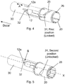
- Distal and proximal are meant to be along an axial orientation extending along the longitudinal axis "X" of the injection device as further indicated in figure 4 and 5 which discloses the front end of the injection device according to a first embodiment.
- Figure 1 discloses the protective cap 10 which proximally is provided with a number of inwardly pointing protrusions 11 which engages the housing structure 20. Internally the protective cap 10 is provided with one or more longitudinal driving protrusions or ribs 12.
- a rib, a track, a protrusion or similar element these can be provided in any number. Since the exemplified embodiments all concern a penshaped injection device with a circular cross section, the ribs, tracks and protrusions referred to are preferably supplied in pairs of two.
- the housing structure 20 is provided with a number of peripheral tracks 21 in which the inwardly pointing protrusions 11 on the protective cap 10 are received. These peripheral tracks 21 are shaped such that the protective cap 10 most be rotated relatively to the housing structure 20 before the protective cap 10 can be removed from the engagement with the housing structure 20.
- the housing structure 20 can either be formed as a single housing or a housing made from any plurality of individual parts coupled together to form a housing structure.
- a housing structure 20 comprises a part securing the mechanical components of the dose setting and injection mechanism and another part securing the cartridge which contains the medicament to be injected.
- Such part is often referred to as the cartridge holder.
- other parts can also be involved in the design of the housing structure 20.
- the housing structure 20 is visually shown as a separate part which is connected to the remaining parts of the housing as disclosed in European patent application Number 16-188751.8 .
- Figure 2 discloses the axially movable shield 30.
- the axially movable shield 30 which covers the distal tip of a needle cannula between injections has a guiding protrusion 31 located at the proximal periphery and an outwardly pointing protrusion 32 also provided on the outer surface. Further, a window 33 is provided for viewing the content of the injection device.
- the axially movable shield 30 can be provided with a cleaning chamber for cleaning the distal tip of the needle cannula between injections. This cleaning chamber will be explained in connection with a later embodiment, but could easily be used for all embodiments..
- the protective cap 10 When the injection device is delivered to the user, the protective cap 10 is pre-mounted by the manufacture onto the housing structure 20 and the inwardly pointing protrusion 11 is located in the peripheral track 21 abutting the end 22 of the peripheral track 21. Opposite to the end 22, the peripheral track 21 terminates in an axial opening 23 through which the inwardly pointing protrusion 11 can be axially removed as the protective cap 10 is removed.
- the guiding protrusion 31 on the axially movable shield 30 is located in the first position as also indicated in the lower section of figure 3 .
- the axially movable shield 30 is prevented from moving in the proximal direction due to the abutment of the guiding protrusion 31 with the radial sidewall of the track 25.
- the track 25 in the housing structure 20 which is engaged by the guiding protrusion 31 guides the axially movable shield 30 between the first position and the second position during rotation of the axially movable shield 30.
- the track 25 connects to an axial track 26 which in the disclosed embodiment is not cut through the housing structure 20 but provided on the inner surface of the housing structure 20.
- the position of the longitudinal driving rib 12 is indicated.
- the inwardly pointing protrusion 11 is rotated to a position in which the protective cap 10 can be axially released from its engagement with the housing structure 20.
- the longitudinal driving ribs 12 inside the protective cap 10 is moved to the position indicated with a broken line 12a in figure 4 . In this position, the protective cap 10 can be axially removed as indicated by the arrow "A".
- the longitudinal driving rib 12 does not abut the axially movable shield 30 which thus remains in its initial rotational position (the locked position).
- the protective cap 10 is henceforth rotated to the axially releasable position while the axially movable shield 30 remains in its locked position.
- the user must manually rotate the axial movable shield 30 back to the first position to lock the injection device. However, should the user forget to manually rotate the axial movable shield 30 this is done automatically when mounts the protective cap 10.
- the longitudinal driving rib 12 When the protective cap 10 is axially positioned on the housing structure 20, the longitudinal driving rib 12 is in the position 12a indicated in figure 4 and 5 . If the axial movable shield 30 has not been rotated back to the locked position, the outwardly pointing protrusion 32 is in the position disclosed in figure 5 . From this position, the user rotates the protective cap 10 clock-wise such that the inwardly pointing protrusion 11 moves peripherally in the peripheral track 21. This rotation of the protective cap 10 and henceforth the longitudinal driving rib 12 moves the outwardly pointing protrusion 32 in the clockwise direction as indicated with the arrow "B" in figure 5 . As the axial movable shield 30 rotate back to the first and locked position, the guiding protrusion 31 moves clockwise in the track 25.
- the housing structure in this second embodiment is thus indicated as “120” and the axially movable shield is numbered “130".
- the housing structure can encompass a cartridge holder which in this second embodiment is referred to as "120A”.
- the housing structure 120 comprises the cartridge holder 120A and a proximal housing part 120B.
- the cartridge holder 120A is provided with one or more protrusions 125 which secure and guide the axially movable shield 130 as will be explained.
- the protrusion 125 is guided in a track 135 which comprises an axial part 136, a helical part 137 and a radial part 138.
- the protrusion 125 When the injection device is delivered to the user, the protrusion 125 is positioned in the radial part 138 of the track 135 as disclosed in figure 6 . In this initial position, the axially movable shield 130 is prevented from axial movement as the protrusion 125 cannot move axially in the radial track 138.
- the user In order to neutralize the pressure in the liquid system, the user needs to rotate the axially movable shield 130 a predetermined angle defined by the track 135 as indicated by the arrow "A" in figure 6 . This rotation moves the protrusion 125 through the helical part 137 of the track 135 and into the axial part 136 of the track 135.
- All movements of the protrusion 125 herein described are relative movements between the protrusion 125 and the track 135.
- the protrusion 125 is provided on the cartridge holder 120A and the track 135 is provided in the axially movable shield 130, however opposite placement as disclosed in the first embodiment generates the same effect.
- the axially movable shield 130 is moved backward in the proximal direction a distance as indicated by the arrow "B" in figure 7 . This distance is determined by the helical pitch of the helical part 137 of the track 135.
- the axially movable shield 130 is thus moved rotationally and axially (i.e. helically) relatively to the cartridge holder 120A and hence the housing structure 120 by an angle defined by the track 135. Further, an additional protrusion 128 engaging a window 133 for limiting the angle of rotation can be provided on the housing structure 120 and preferably on the cartridge holder 120A of the housing structure 120.
- the window 133 in the axially movable shield 130 can further be aligned with a similar longitudinal opening 127 provided in the cartridge holder 120A such that the liquid drug inside the cartridge 105 can only be viewed when the window 133 is aligned with the longitudinal opening 127 as disclosed in figure 7 . This further indicates to the user that the injection device is in a position ready to perform an injection.
- the outer surface of the axially movable shield 130 is further provided with an outwardly pointing protrusion 132 which is engaged by the protective cap 110 in order to rotate the axially movable shield 130 back to the first locked position should the user forget to do this manually.
- This outwardly pointing protrusion 132 can be formed as a regular protrusion as depicted in figure 7 or alternatively as a longitudinal rib as depicted in figure 9 .
- the engaging surface on the protective cap 110 is also in this embodiment formed as an inwardly pointing longitudinal rib structure 112 as indicated in figure 10 .
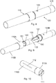
- FIG. 8 and figure 9 are perspective views of the injection device according to the second embodiment.
- minor deviations in the individual drawings can occur.
- the housing structure 120 is proximally provided with a dose setting button 115 and distally with the axially movable shield 130.
- the protective cap 110 which has been removed in the figures 11 and 12 covers the distal end of the injection device during storage and is usually only removed when the user performs an injection.
- the proximal housing part 120B of the housing structure 120 is externally provided with a protrusion 121 which engages a helical track 111 located inside the protective cap 110 as best seen in figure 10 . Since the track 111 is helical, the user needs to rotate the protective cap 110 relatively to the housing structure 120 in order to remove the protective cap 110.
- the protective cap 110 which in the first embodiment was moulded as one unitary unit is in this second embodiment formed from two parts 110A, 110B which in one example are moulded in a 2K moulding.
- the protective cap 10 can be made from two individual and separately moulded parts which are click-fitted together as will be explained in the third embodiment.
- the protective cap 110 has been removed by rotating the protective cap 110 relatively to the protrusion 121 on the proximal housing part 120B. Further, in figure 9 , the axially movable shield 130 has been rotated to the second unlocked position and the distal part 151 of the needle cannula 150 is thus visible.
- the axially movable shield 130 is distally provided with a cleaning unit 140 which are shown in more details on figure 11 and 12 . Further, on figure 9 , the outwardly pointing protrusion 132 provided on the axially movable shield 130 is depicted as a longitudinal rib.
- the figures 11 and 12 disclose a cross sectional view of the distal end of injection device of the second embodiment with the protective cap 110 fully removed.
- the cartridge holder 120A is secured to the proximal housing part 120B by having the protrusions 125 penetrate further though holes in the proximal housing part 120B.
- the cartridge-holder 120A secures the cartridge 105 which contain a liquid drug.
- This liquid drug preferably contains a preservative such as meta-cresol, phenol or similar preservative.
- the cartridge 105 is typically a hollow cylinder-shaped container which is distally provided with a pierceable septum 106 and proximally provided with a movable plunger 107 which can be moved in the distal direction to force the liquid drug out of the cartridge 105 through the needle cannula 150 penetrated through the distal septum 106.
- the pierceable septum 106 and the movable plunger 107 thus define an interior 108 containing the liquid drug.
- the needle cannula 150 has a distal end 151 with a distal tip 152 and a proximal end 153 which are connected via a lumen through which the liquid drug flows.
- the distal tip 152 penetrates through the skin of the user during injection and the proximal end 153 penetrates into the cartridge 105.
- the proximal housing part 120B holds the dose setting and injecting mechanism which could be any kind of manually working or spring operated mechanism.
- the dose setting and injecting mechanism moves a piston rod 118 in the distal direction during injection and the piston rod 118 abuts and moves the plunger 107 forward inside the cartridge 105.
- a piston rod foot 119 is provided between the piston rod 118 and the plunger 107 to distribute the force
- a axially movable shield 130 is provided on the outside surface of the cartridge holder 120A.
- This axially movable shield 130 is movable relatively to the cartridge holder 120A between a first position and a second position and since the cartridge holder 120A is permanently connected to the proximal housing part 120B, the axially movable shield 130 also moves relatively to the proximal housing part 120B and thus to the entire housing structure 120.
- a compression spring S1 is located between the proximal housing part 120B and the axially movable shield 130. The purpose of this compression spring S1 is to return the axially movable shield 130 to its initial position following an injection.
- the axially movable shield 130 carries a cleaning unit 140 which comprises a cleaning chamber 145 containing a cleaning solvent for cleaning the distal tip 152 of the needle cannula 150 between subsequent injections.
- the cleaning solvent contained in the cleaning chamber 145 is preferably an amount of the liquid drug contained in the cartridge 105 as explained in WO2015/062845 .
- such liquid drug contains a preservative such as meta-cresol or phenol or a combination thereof which thus acts as the cleaning solvent.
- the liquid drug can be any kind of injectable liquid drug but is preferably a blood sugar regulating liquid drug such as insulin, insulin analogue, GLP-1 or GLP-2 or a combination of any of these liquid drugs.
- a predetermined amount of the liquid drug contained in the cartridge 105 is transferred to the cleaning chamber 145 which is defined between the seal 146 and the piston 147.
- the initialization process has two steps. First the needle cannula 150 is moved into the position depicted in figure 11 . In this position, the proximal end 153 of the needle cannula 150 is penetrated into the interior 108 of the cartridge 105 and the distal tip 152 is positioned inside the cleaning chamber 145. Further, in the following step of the initialization process an amount of the liquid drug is pumped from the cartridge 105 and into the cleaning chamber 145 by pressurizing the liquid drug inside the cartridge 105 either by moving the plunger 107 forward or by moving the cartridge 105 proximally while maintaining the position of the plunger 107.
- the cartridge holder 120A is provided with the protrusion 125 engaging the track 135.
- the protrusion 125 is positioned in the radial part 138 of the track 135.
- the axially movable shield 130 is thus prevented from axial movement.
- the protrusion 125 is moved through the helical part 137 of the track 135 and into the axial part 136.
- the axially movable shield 130 has been retracted such that the distal tip 152 of the needle cannula 150 is positioned in front of the axially movable shield 130 but preferably within a concave recess 141 provided distally in the cleaning unit 140 secured to the axially movable shield 130.
- the cleaning unit 140 can also be an integral part of the axially movable shield 130.
- the user removes the axially movable shield 130 from the skin of the user, and the spring S1 automatically returns the axially movable shield 130 to the second position disclosed in figure 12 . From this position, the user can once again lock the axial movement of the axially movable shield 130 by rotating the axially movable shield 130. Such rotation moves the axially movable shield distally due to the helical part 137 of the track 135 where after the distal tip 152 of the needle cannula 150 is once again positioned inside the cleaning chamber 145 as disclosed in figure 11 .
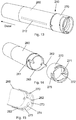
- the third embodiment explains the two-part protective cap as disclosed in the figures 13 - 19B . Similar constructive elements are provided with the same reference numeral, however, with a "2" in front.
- the protective cap is henceforth in this third embodiment referred to as "210".
- the protective cap 110 is formed from two different and separate parts; a distal part 260 and a proximal part 270.
- the distal part 260 is the actual cap and the proximal part 270 is a ring shaped element as best seen in figure 14 .
- the distal part 260 has a number of openings 261 into which a similar number of radial protrusions 271 provided on the inner surface of the proximal part 270 fits such that the two parts 260, 270 can be clicked together to form one operational protective cap 210.
- the distal part 260 is further provided with a number of guiding noses 262 which slides into axial tracks 272 in the proximal part 270.
- a part of the axial track 272 is left open to form an axial guiding track or opening 273 as best seen in figure 15 .
- the protective cap 210 is also in the second embodiment provided with a driving rib 212 provided on the inner surface as indicated by punctured lines in figure 13 .
- This axial guiding track 273 fits over outwardly pointing protrusions 221 provided on the proximal housing part 220B of the housing structure 220 as best seen in figure 16A and 16B .
- the housing structure 220 comprise of a not-shown cartridge holder and a proximal housing part 220B.
- the guiding track 273 further leads to a peripheral track 274 which are provided between the distal part 260 and the proximal part 270 as best seen in figure 15 .
- the peripheral track 274 is provided between the proximal end surface 263 of the distal part 260 and a mould surface 275 provided in the proximal part 270.
- the outwardly pointing housing protrusion 221 moves in this peripheral track 274 which forces the user to rotate the protective cap 210 relatively to the housing structure 220 before the outwardly pointing housing protrusion 221 can enter the axial track 273 and the protective cap 210 can be mounted or removed.
- the peripheral track 274 can as depicted in figure 15 be slightly helical.
- the user after having removed the protective cap 210, rotates the axially movable shield 230 to an unlocked position and performs an injection. Should the user forget to manually rotate the axially movable shield 230 back to the locked position this is done automatically upon mounting of the protective cap 210 as will be explained in conjunction with figure 16A-B and figure 17A-B .
- Figure 16A-B discloses the state in which the axially movable shield 230 is in the second and unlocked position.
- the user mounts the protective cap 210 by inserting the track 273 over the outwardly pointing housing protrusion 221.
- the longitudinal driving rib 212 is placed in an anti-clockwise position in relation to the outwardly pointing protrusion 232 on the axially movable shield 230.
- Figure 17B depicts the situation in which the outwardly pointing housing protrusion 221 is positioned approximately halfway in the peripheral track 274 and further rotation forces the outwardly pointing protrusion 232 and thus the axially movable shield 230 clockwise back into the first and locked position.
- the peripheral track 21 was formed as a purely radial track whereas in the second and third embodiments the peripheral track 274 is formed as a helical track such that the protective cap 210 is also moved axially during mounting and removal of the protective cap 210.
- longitudinal driving rib 212 located in a clockwise position relatively to the outwardly pointing protrusion 132. This is e.g. disclosed in figure 18A-B .
- the outwardly pointing housing protrusion 221 is located at the end of the peripheral track 274 furthest away from the axial guiding track 273.
- the longitudinal driving rib 212 abuts the outwardly pointing protrusion 232 and rotates the axially movable shield 230.
- This initial rotation of the axially movable shield 230 can e.g. be used in an initiation process of the injection device as explained in European patent application number EP 16-188751.8 .
- Figure 19A-B discloses the position in which the protective cap 210 has been rotated to a position in which the outwardly pointing housing protrusion 221 can slide axially through the axial guiding track 273. The user is thus able to axially remove the protective cap 210.
- the user rotates the axially movable shield 230 to unlock the axially movable shield 230.
- the axially movable shield 230 is thus rotated from the position depicted in figure 19B to the position disclosed in figure 16B .
- the longitudinal driving rib 221 will thus be on the anti-clockwise side of the outwardly pointing protrusion 232 as depicted in figure 16B .
- the longitudinal driving rib 221 is to be initial located in the clockwise position relatively to the outwardly pointing protrusion 232 as depicted in figure 11A-B and figure 12A-B , it is necessary to split the protective cap 210 in two parts such as a distal part 260 and a proximal part 270.
- the proximal part 270 When initially mounting the two-part protective cap 210 onto the housing structure 220 during manufacturing of the injection device, the proximal part 270 is first placed in the position depicted in figure 18A with the outwardly pointing housing protrusion 221 located at the end of the peripheral track 274.
- distal part 260 is slid axially into its click-fit connection with the proximal part 270 such that the longitudinal driving rib 212 is positioned clockwise to the outwardly pointing protrusion 32 as disclosed in figure 18B .
Description
- The invention relates to a medical injection device for injecting a liquid drug and especially to a pre-filled injection device for apportioning a plurality of individual settable doses. The invention especially relates to such pre-filled injection device wherein the needle cannula is covered and protected by a retractable shield between subsequent injections.
- The invention further relates to a method of attaching a protective cap to a housing structure of such injection device.
- Pen shaped injection devices for self-treatment of chronical disease having an axially retractable axially movable shield which covers and protects the needle cannula between injections are e.g. known from
WO 2016/041883 . -
WO 2016/041883 discloses a pen shaped injection device in which the distal part of the housing structure including the axially movable shield is covered by a removable protective cap. In order to perform an injection, the user needs to physically remove this protective cap which is usually done by pulling the protective cap axially off and away from the housing structure. - It is however sometimes desirable if the axially movable shield is provided with a locking mechanism such that the axially movable shield can only be moved in the proximal direction during injection when the locking mechanism has been activated and unlocked.
-
WO 2016/162284 discloses a pen shaped injection device in which the distal part of the housing structure is covered by a protective cap. However, in this injection device the protective cap is distally provided with engaging means on the inner surface which engages the axially movable shield such that a rotation of the protective cap can be transformed to a similar rotation of the axially movable shield. -
WO 2015090320 discloses a pen shaped injection device with a lock arrangement involving a rotation of two sleeve elements in rotational engagement. - The axially movable shield is rotatable relatively to the housing structure between two different positions. In the first rotational position as depicted in
figure 7 , the axially movable shield is prevented from moving in the proximal direction and in the second rotational position as depicted infigure 8 , the axially movable shield is allowed to move proximally. - The locked and unlocked positions are controlled by a track configuration in the axially movable shield which track configuration is rotated and moved relatively to an outwardly pointing protrusion.
- The injection device is usually kept with the axially movable shield in the first and locked position between injections thereby avoiding unnecessary exposure of the needle cannula and the axially movable shield is only rotated to the second and unlocked position just before an injection is to be performed. The user thus unlocks the axially movable shield simply by rotating the axially movable shield from the first locked position to the second unlocked position.
- Following an injection the user places the protective cap onto the distal part of the housing in an axial movement. However, in order to lock the axial movement of the axially movable shield the user needs to remember to rotate the axially movable shield back to the first position, either by manually rotating the axially movable shield or by rotating the protective cap engaging the axially movable shield after its mounting on the housing.
- If the user forgets to rotate the axially movable shield back to the locked position there is a risk of damaging the needle cannula. This is particular cumbersome if the user either leaves the needle cannula on the injection device between injections or if the injection device is the type wherein the same needle cannula is permanently mounted and intended to be used for multiple injections.
- It is an object of the present invention to provide an injection device having a shielded needle cannula which simplifies the handling of the unlocking and locking of the axial movable shield. It is in particular the intention to improve the return rotation of the axial movable shield to the locked position.
- Accordingly, in one aspect, the present invention relates to a prefilled injection pen for apportioning multiple doses of a liquid drug. The injection device comprises:
- A housing structure which supports a non-removable cartridge containing the liquid drug to be ejected,
- A needle cannula having a proximal end inserted into the cartridge and a distal end with a distal tip for penetrating the skin of a user,
- An axially movable shield which covers at least the distal tip of the needle cannula between subsequent injections. This axially movable shield is rotatable relatively to the housing structure between a first position and a second positon.
- ∘ In the first position the axially movable shield is locked i.e. prevented from movements in the proximal direction and,
- ∘ In the second position, the axially movable shield is unlocked i.e. allowed to move in the proximal direction.
- A removable protective cap rotatably coupled to the housing structure and covering the distal part of the housing structure and the distal tip of the needle cannula when mounted on the housing structure.
- As the protective cap is rotatably coupled to the housing structure it requires rotation of the protective cap relative to the housing in order to allow removal of the protective cap. Further, the protective cap comprises means which rotationally engages the axially movable shield such that the required rotation of the protective during removable is transformed to a rotation of the axially movable shield.
- When following an injection the user mounts the protective cap onto the housing structure, the user is forced to rotate the protective cap due to its rotatable engagement with the housing structure. Via the means for engaging the axially movable shield this rotational movement of the protective cap is conveyed to a similar rotation of the axially movable shield. In this way, the axially movable shield is rotated from the second unlocked position and back to the first locked position simply by the user mounting the protective cap onto the housing structure.
- Henceforth, should the user forget to lock the axially movable shield following an injection, this will be automatically done when the user mounts the protective cap on the housing structure following an injection.
- The protective cap is manually removable meaning that the user of the injection device is able to both mount and dismount the protective cap by simple manipulation with the hands.
- The means on the protective cap engaging the axially movable shield are provided on an inner surface of the protective cap and are formed as one or more protrusions or longitudinal structures such as ribs. Any number of such ribs can be provided but the preference is to have no less than two such ribs. The length of the ribs can also vary as long as the ribs properly engage the axially movable shield.
- The axially movable shield is provided with a number of outwardly pointing protrusions or the like which is engaged by the protrusions or longitudinal ribs on the protective cap to thereby transfer rotation from the protective cap to the axially movable shield. The number of outwardly pointing protrusions preferably matches the number of longitudinal ribs. The outwardly pointing protrusions can have any suitable form.
- The forced rotation of the protective cap relatively to the housing is created by a protrusion on one of the parts being guided in a track provided on the other part. In one example, the protective cap carries the inwardly pointing protrusions and the housing structure carries one or more peripheral tracks in which peripheral tracks the inwardly pointing protrusions are guided during rotation of the protective cap. However, in a different embodiment the kinematic has been reversed and the protective cap carries the peripheral track or tracks in which one or more outwardly pointing protrusions provided on the housing structure are guided.
- The essential feature is that the user is forced to rotate the protective cap relatively to the housing structure in order to remove and remount the protective cap and that this rotation, at least during mounting of the protective cap, is transformed to a simultaneous rotation of the axially movable shield into its locked position thereby securing that the axial movement of the axially movable shield is not possible after mounting of the protective cap.
- Further, the peripheral track connects to an axial track or opening allowing the user to fully remove the protective cap after the cap has been rotated. This final removal of the protective cap is preferably done by pulling the protective cap axially away from the housing structure.
- The peripheral track can either be formed on an outer surface of the housing structure or on an inner surface of the protective cap. The peripheral track can be formed such that the protective cap is rotated purely rotationally without any axial movement during rotation or the peripheral track can be helically shaped such that the protective cap also move axially as it is rotated relatively to the housing structure.
- In one example, the protective cap comprises a distal part and a proximal part which coupled together to form one operational protective cap. The parts are preferably coupled together by a simple snap- or click fit such that one part carries a counter sunk well or an opening and the other part carries a protrusion or a snap- or click arm insertable into the well or opening. However, the two parts can be connected in many alternative ways.
- In this example, the peripheral track is preferably positioned in the junction between the distal part and the proximal part and preferably on an inner surface thereof.
- During manufacturing, when initially mounting the protective cap onto the housing, the proximal part is first secured to the housing and the outwardly pointing protrusion is positioned in a start position in the peripheral track. Following this, the distal part is mounted by moving the distal part purely axially in relation to the housing structure. However, the distal part and the proximal part can be mounted in any random order.
- When initially mounting the protective cap, the longitudinal rib can be positioned in a start position in which it will abut and rotate the axially movable shield also when the protective cap is removed for the first time. This makes it possible to use the initial rotation of the protective cap and henceforth the axially movable shield in an initiation procedure.
- Such initiation procedure is in one example used to fill liquid drug from the cartridge and into a cleaning chamber which can be carried distally on the axially movable shield.
- A cleaning chamber is provided so that the distal tip of the needle cannula is located inside the cleaning chamber when the axially movable shield is in the first position, and the distal tip is located outside and distal to the cleaning chamber when the axially movable shield is in the second position.
- Such initiation procedure is further described in European patent application number:
EP 16 188751.8 - The preservatives contained in the liquid drug are thus used as a cleaning solvent for cleaning the distal tip of the needle cannula between injections. Well known preservatives for liquid drugs are e.g. phenol or meta-cresol or a combination thereof as disclosed in
WO 2015/062845 . - The present invention further relates to a method of initially attaching a protective cap to a housing structure wherein the protective cap is assembled from multiple parts.
- Such method comprises the steps of:
- i) Initially positioning a proximal part of the protective cap relatively to the housing structure, and
- ii) Moving a distal part of the protective cap axially into contact and attachment with the proximal part of the protective cap.
- The proximal part is preferably mounted over the housing structure where after it is manipulated to the correct start position relatively to the outwardly pointing protrusion on the housing structure.
- Once this is done the distal part is slided axially over the housing structure and into engagement with the proximal part. The connection between the two parts is preferably a snap or click connection.
-
- An "injection pen" is typically an injection apparatus/device having an oblong or elongated shape somewhat like a pen for writing. Although such pens usually have a tubular cross-section, they could easily have a different cross-section such as triangular, rectangular or square or any variation around these geometries.
- The term "Needle Cannula" is used to describe the actual conduit performing the penetration of the skin during injection. A needle cannula is usually made from a metallic material such as e.g. stainless steel and preferably connected to a needle hub to form a complete injection needle, all though the needle cannula could also be connected directly to the housing structure without a needle hub. A needle cannula could however also be made from a polymeric material or a glass material.
- As used herein, the term "drug" is meant to encompass any drug-containing flowable medicine capable of being passed through a delivery means such as a hollow needle in a controlled manner, such as a liquid, solution, gel or fine suspension. Representative drugs includes pharmaceuticals such as peptides, proteins (e.g. insulin, insulin analogues and C-peptide), and hormones, biologically derived or active agents, hormonal and gene based agents, nutritional formulas and other substances in both solid (dispensed) or liquid form.
- "Cartridge" is the term used to describe the container actually containing the drug. Cartridges are usually made from glass but could also be moulded from any suitable polymer. A cartridge or ampoule is preferably sealed at one end by a pierceable membrane referred to as the "septum" which can be pierced e.g. by the non-patient end of a needle cannula. Such septum is usually self-sealing which means that the opening created during penetration seals automatically by the inherent resiliency once the needle cannula is removed from the septum. The opposite end is typically closed by a plunger or piston made from rubber or a suitable polymer. The plunger or piston can be slidable moved inside the cartridge. The space between the pierceable membrane and the movable plunger holds the drug which is pressed out as the plunger decreased the volume of the space holding the drug. However, any kind of container - rigid or flexible - can be used to contain the drug.
- Since a cartridge usually has a narrower distal neck portion into which the plunger cannot be moved not all of the liquid drug contained inside the cartridge can actually be expelled. The term "initial quantum" or "substantially used" therefore refers to the injectable content contained in the cartridge and thus not necessarily to the entire content.
- By the term "Pre-filled" injection device is meant an injection device in which the cartridge containing the liquid drug is permanently embedded in the injection device such that it cannot be removed without permanent destruction of the injection device. Once the pre-filled amount of liquid drug in the cartridge is used, the user normally discards the entire injection device. This is in opposition to a "Durable" injection device in which the user can himself change the cartridge containing the liquid drug whenever it is empty. Pre-filled injection devices are usually sold in packages containing more than one injection device whereas durable injection devices are usually sold one at a time. When using pre-filled injection devices an average user might require as many as 50 to 100 injection devices per year whereas when using durable injection devices one single injection device could last for several years, however, the average user would require 50 to 100 new cartridges per year.
- The term "protective cap" is herein meant to refer to a cover or a sleeve-like structure which is mounted at the distal end of the injection device between injections. Such cover or sleeve-like structure is closed at the distal end. The protective cap covers and protects the distal end of the injection device between injections. Should a needle cannula be mounted to the injection device, either permanently or exchangeable, such needle cannula is henceforth also protected by the protective cap. Since the protective cap is mounted each time an injection has been performed, the word "re-mounted" can also be used to describe the mounting of the protective cap. Further, since the housing structure of an injection device often has a window through which the user can inspect the liquid drug, the protective cap also protect the drug from long time exposure to light as some liquids drug are sensitive to light exposure, especially to UV light.
- All headings and sub-headings are used herein for convenience only and should not be constructed as limiting the invention in any way.
The use of any and all examples, or exemplary language (e.g. such as) provided herein, is intended merely to better illuminate the invention and does not pose a limitation on the scope of the invention unless otherwise claimed. No language in the specification should be construed as indicating any non-claimed element as essential to the practice of the invention. - The citation and incorporation of patent documents herein is done for convenience only and does not reflect any view of the validity, patentability, and/or enforceability of such patent documents.
This invention includes all modifications and equivalents of the subject matter recited in the claims appended hereto as permitted by applicable law. - The invention will be explained more fully below in connection with a preferred embodiment and with reference to the drawings in which:
- Figure 1
- show a cross sectional view of the protective cap according to a first example of the invention.
- Figure 2
- show a perspective view of the axially movable and rotatable shield according to the first example.
- Figure 3
- show a perspective view of the coupling between the housing structure and the protective cap according to the first example.
- Figure 4
- show a perspective view of the axially movable shield in the first and locked position in relation to the housing structure.
- Figure 5
- show a perspective view of the axially movable shield in the second and unlocked position in relation to the housing structure.
- Figure 6
- show a perspective view of the engagement between the housing structure and the axially movable shield with the axially movable shield in the first rotatable position
- Figure 7
- show a perspective view of the engagement between the housing structure and the axially movable shield with the axially movable shield in the second rotatable position.
- Figure 8
- show a perspective view of the injection device according to a second example with the protective cap attached to the housing structure.
- Figure 9
- show a perspective view of the injection device according to the second example with the protective cap dismounted.
- Figure 10
- show a perspective view of the protective cap according to the second and third example.
- Figure 11
- show a cross-sectional view of the distal part of the injection device with the axially movable shield in the first position.
- Figure 12
- show a cross-sectional view of the distal part of the injection device with the axially movable shield in the second position.
- Figure 13
- show a perspective view of the protective two-part cap.
- Figure 14
- show a perspective view of the distal part and the proximal part making up the protective two-part cap.
- Figure 15
- show a close-up view of the track configuration of the protective two part cap.
- Figure 16A
- show a perspective view of the injection device of a third example wherein the protective cap (with parts visually cut away) is being axially mounted onto the housing structure.
- Figure 16B
- show a side view of the injection device shown in
figure 16A . - Figure 17A
- show a perspective view of the injection device according to the third example wherein the protective cap (with parts visually cut away) is being rotated relatively to the housing structure.
- Figure 17B
- show a side view of the injection device shown in
figure 17A . - Figure 18A-B
- show a side view of the protective two-part cap and the housing structure as the longitudinal driving rib inside the protective two-part cap drives the outwardly pointing protrusion of the axially movable shield during an initiation process.
- Figure 19A-B
- show a side view of the protective two-part cap and the housing structure as the protective two-part cap is being axially removed from the housing structure.
- The figures are schematic and simplified for clarity, and they just show details, which are essential to the understanding of the invention, while other details are left out. Throughout, the same reference numerals are used for identical or corresponding parts.
- When in the following terms as "upper" and "lower", "right" and "left", "horizontal" and "vertical", "clockwise" and "counter clockwise" or similar relative expressions are used, these only refer to the appended figures and not to an actual situation of use. The shown figures are schematic representations for which reason the configuration of the different structures as well as their relative dimensions are intended to serve illustrative purposes only.
- In that context it may be convenient to define that the term "distal end" in the appended figures is meant to refer to the end of the injection device which usually carries the protective cap whereas the term "proximal end" is meant to refer to the opposite end pointing away from the protective cap and usually carrying the dose dial button.
- As the figures are merely schematic representations some deviations between the different drawings, even within the same embodiments, can occur without influencing the claimed invention.
- Distal and proximal are meant to be along an axial orientation extending along the longitudinal axis "X" of the injection device as further indicated in
figure 4 and 5 which discloses the front end of the injection device according to a first embodiment. -
Figure 1 discloses theprotective cap 10 which proximally is provided with a number of inwardly pointingprotrusions 11 which engages thehousing structure 20. Internally theprotective cap 10 is provided with one or more longitudinal driving protrusions orribs 12. - Whenever in the following reference is made to a rib, a track, a protrusion or similar element these can be provided in any number. Since the exemplified embodiments all concern a penshaped injection device with a circular cross section, the ribs, tracks and protrusions referred to are preferably supplied in pairs of two.
- As best seen in
figure 3 , thehousing structure 20 is provided with a number ofperipheral tracks 21 in which the inwardly pointingprotrusions 11 on theprotective cap 10 are received. Theseperipheral tracks 21 are shaped such that theprotective cap 10 most be rotated relatively to thehousing structure 20 before theprotective cap 10 can be removed from the engagement with thehousing structure 20. - The
housing structure 20 can either be formed as a single housing or a housing made from any plurality of individual parts coupled together to form a housing structure. Usually ahousing structure 20 comprises a part securing the mechanical components of the dose setting and injection mechanism and another part securing the cartridge which contains the medicament to be injected. Such part is often referred to as the cartridge holder. However, other parts can also be involved in the design of thehousing structure 20. - In the first embodiment disclosed in the
figures 1 to 5 , thehousing structure 20 is visually shown as a separate part which is connected to the remaining parts of the housing as disclosed in European patent application Number16-188751.8 -
Figure 2 discloses the axiallymovable shield 30. The axiallymovable shield 30 which covers the distal tip of a needle cannula between injections has a guidingprotrusion 31 located at the proximal periphery and an outwardly pointingprotrusion 32 also provided on the outer surface. Further, awindow 33 is provided for viewing the content of the injection device. Distally the axiallymovable shield 30 can be provided with a cleaning chamber for cleaning the distal tip of the needle cannula between injections. This cleaning chamber will be explained in connection with a later embodiment, but could easily be used for all embodiments.. - When the injection device is delivered to the user, the
protective cap 10 is pre-mounted by the manufacture onto thehousing structure 20 and the inwardly pointingprotrusion 11 is located in theperipheral track 21 abutting theend 22 of theperipheral track 21. Opposite to theend 22, theperipheral track 21 terminates in anaxial opening 23 through which the inwardly pointingprotrusion 11 can be axially removed as theprotective cap 10 is removed. - In the first locked position disclosed in
figure 4 , the guidingprotrusion 31 on the axiallymovable shield 30 is located in the first position as also indicated in the lower section offigure 3 . In this first position, the axiallymovable shield 30 is prevented from moving in the proximal direction due to the abutment of the guidingprotrusion 31 with the radial sidewall of thetrack 25. - The
track 25 in thehousing structure 20 which is engaged by the guidingprotrusion 31 guides the axiallymovable shield 30 between the first position and the second position during rotation of the axiallymovable shield 30. As seen from thefigures 4 and 5 , thetrack 25 connects to anaxial track 26 which in the disclosed embodiment is not cut through thehousing structure 20 but provided on the inner surface of thehousing structure 20. - In the
figures 4 and 5 the position of thelongitudinal driving rib 12 is indicated. When the user rotationally removes theprotective cap 10 by anti-clockwise rotation as seen infigure 3 , the inwardly pointingprotrusion 11 is rotated to a position in which theprotective cap 10 can be axially released from its engagement with thehousing structure 20. During anti clock-wise rotation of theprotective cap 10 in order to remove theprotective cap 10, thelongitudinal driving ribs 12 inside theprotective cap 10 is moved to the position indicated with abroken line 12a infigure 4 . In this position, theprotective cap 10 can be axially removed as indicated by the arrow "A". During the rotation of theprotective cap 10, thelongitudinal driving rib 12 does not abut the axiallymovable shield 30 which thus remains in its initial rotational position (the locked position). Theprotective cap 10 is henceforth rotated to the axially releasable position while the axiallymovable shield 30 remains in its locked position. - Once the user has rotated the
protective cap 10 and removed it axially along the arrrow "A", the user must manually rotate the axiallymovable shield 30 to the second (unlocked) position disclosed in the upper part offigure 3 and infigure 5 . In this second unlocked position, the axiallymovable shield 30 is free to move axially as the guidingprotrusion 31 moves axially in theaxial track 26 and an injection can henceforth be performed. - Following the injection, the user must manually rotate the axial
movable shield 30 back to the first position to lock the injection device. However, should the user forget to manually rotate the axialmovable shield 30 this is done automatically when mounts theprotective cap 10. - When the
protective cap 10 is axially positioned on thehousing structure 20, thelongitudinal driving rib 12 is in theposition 12a indicated infigure 4 and 5 . If the axialmovable shield 30 has not been rotated back to the locked position, the outwardly pointingprotrusion 32 is in the position disclosed infigure 5 . From this position, the user rotates theprotective cap 10 clock-wise such that the inwardly pointingprotrusion 11 moves peripherally in theperipheral track 21. This rotation of theprotective cap 10 and henceforth thelongitudinal driving rib 12 moves the outwardly pointingprotrusion 32 in the clockwise direction as indicated with the arrow "B" infigure 5 . As the axialmovable shield 30 rotate back to the first and locked position, the guidingprotrusion 31 moves clockwise in thetrack 25. - In the second embodiment disclosed in
figure 6 to 12 , similar constructive elements are provided with the same reference numeral, however, with a "1" in front. The housing structure in this second embodiment is thus indicated as "120" and the axially movable shield is numbered "130". As previously mentioned such housing structure can encompass a cartridge holder which in this second embodiment is referred to as "120A". Henceforth, in this second embodiment thehousing structure 120 comprises thecartridge holder 120A and aproximal housing part 120B. - The
cartridge holder 120A is provided with one ormore protrusions 125 which secure and guide the axiallymovable shield 130 as will be explained. Theprotrusion 125 is guided in atrack 135 which comprises anaxial part 136, ahelical part 137 and aradial part 138. - When the injection device is delivered to the user, the
protrusion 125 is positioned in theradial part 138 of thetrack 135 as disclosed infigure 6 . In this initial position, the axiallymovable shield 130 is prevented from axial movement as theprotrusion 125 cannot move axially in theradial track 138. - In order to neutralize the pressure in the liquid system, the user needs to rotate the axially movable shield 130 a predetermined angle defined by the
track 135 as indicated by the arrow "A" infigure 6 . This rotation moves theprotrusion 125 through thehelical part 137 of thetrack 135 and into theaxial part 136 of thetrack 135. - All movements of the
protrusion 125 herein described are relative movements between theprotrusion 125 and thetrack 135. As shown in the second embodiment, theprotrusion 125 is provided on thecartridge holder 120A and thetrack 135 is provided in the axiallymovable shield 130, however opposite placement as disclosed in the first embodiment generates the same effect. - As the
protrusion 125 moves through thehelical part 137 of thetrack 135, the axiallymovable shield 130 is moved backward in the proximal direction a distance as indicated by the arrow "B" infigure 7 . This distance is determined by the helical pitch of thehelical part 137 of thetrack 135. - The axially
movable shield 130 is thus moved rotationally and axially (i.e. helically) relatively to thecartridge holder 120A and hence thehousing structure 120 by an angle defined by thetrack 135. Further, anadditional protrusion 128 engaging awindow 133 for limiting the angle of rotation can be provided on thehousing structure 120 and preferably on thecartridge holder 120A of thehousing structure 120. - The
window 133 in the axiallymovable shield 130 can further be aligned with a similarlongitudinal opening 127 provided in thecartridge holder 120A such that the liquid drug inside thecartridge 105 can only be viewed when thewindow 133 is aligned with thelongitudinal opening 127 as disclosed infigure 7 . This further indicates to the user that the injection device is in a position ready to perform an injection. - The outer surface of the axially
movable shield 130 is further provided with an outwardly pointingprotrusion 132 which is engaged by theprotective cap 110 in order to rotate the axiallymovable shield 130 back to the first locked position should the user forget to do this manually. This outwardly pointingprotrusion 132 can be formed as a regular protrusion as depicted infigure 7 or alternatively as a longitudinal rib as depicted infigure 9 . The engaging surface on theprotective cap 110 is also in this embodiment formed as an inwardly pointinglongitudinal rib structure 112 as indicated infigure 10 . - A more detailed view of the injection device as partly disclosed in
figure 6 and 7 are provided in thefigures 8 to 12 whereinfigure 8 and figure 9 are perspective views of the injection device according to the second embodiment. However, minor deviations in the individual drawings can occur. - The
housing structure 120 is proximally provided with adose setting button 115 and distally with the axiallymovable shield 130. Theprotective cap 110, which has been removed in thefigures 11 and 12 covers the distal end of the injection device during storage and is usually only removed when the user performs an injection. - As best seen in
figure 9 , theproximal housing part 120B of thehousing structure 120 is externally provided with aprotrusion 121 which engages ahelical track 111 located inside theprotective cap 110 as best seen infigure 10 . Since thetrack 111 is helical, the user needs to rotate theprotective cap 110 relatively to thehousing structure 120 in order to remove theprotective cap 110. - The
protective cap 110 which in the first embodiment was moulded as one unitary unit is in this second embodiment formed from twoparts protective cap 10 can be made from two individual and separately moulded parts which are click-fitted together as will be explained in the third embodiment. - In
figure 9 , theprotective cap 110 has been removed by rotating theprotective cap 110 relatively to theprotrusion 121 on theproximal housing part 120B. Further, infigure 9 , the axiallymovable shield 130 has been rotated to the second unlocked position and thedistal part 151 of theneedle cannula 150 is thus visible. - As further disclosed in
figure 9 , the axiallymovable shield 130 is distally provided with acleaning unit 140 which are shown in more details onfigure 11 and 12 . Further, onfigure 9 , the outwardly pointingprotrusion 132 provided on the axiallymovable shield 130 is depicted as a longitudinal rib. - The
figures 11 and 12 disclose a cross sectional view of the distal end of injection device of the second embodiment with theprotective cap 110 fully removed. - The
cartridge holder 120A is secured to theproximal housing part 120B by having theprotrusions 125 penetrate further though holes in theproximal housing part 120B. The cartridge-holder 120A secures thecartridge 105 which contain a liquid drug. This liquid drug preferably contains a preservative such as meta-cresol, phenol or similar preservative. - The
cartridge 105 is typically a hollow cylinder-shaped container which is distally provided with apierceable septum 106 and proximally provided with amovable plunger 107 which can be moved in the distal direction to force the liquid drug out of thecartridge 105 through theneedle cannula 150 penetrated through thedistal septum 106. Thepierceable septum 106 and themovable plunger 107 thus define an interior 108 containing the liquid drug. - The
needle cannula 150 has adistal end 151 with adistal tip 152 and aproximal end 153 which are connected via a lumen through which the liquid drug flows. Thedistal tip 152 penetrates through the skin of the user during injection and theproximal end 153 penetrates into thecartridge 105. - The
proximal housing part 120B holds the dose setting and injecting mechanism which could be any kind of manually working or spring operated mechanism. The dose setting and injecting mechanism moves apiston rod 118 in the distal direction during injection and thepiston rod 118 abuts and moves theplunger 107 forward inside thecartridge 105. Usually apiston rod foot 119 is provided between thepiston rod 118 and theplunger 107 to distribute the force - On the outside surface of the
cartridge holder 120A, a axiallymovable shield 130 is provided. This axiallymovable shield 130 is movable relatively to thecartridge holder 120A between a first position and a second position and since thecartridge holder 120A is permanently connected to theproximal housing part 120B, the axiallymovable shield 130 also moves relatively to theproximal housing part 120B and thus to theentire housing structure 120. A compression spring S1 is located between theproximal housing part 120B and the axiallymovable shield 130. The purpose of this compression spring S1 is to return the axiallymovable shield 130 to its initial position following an injection. - Distally the axially
movable shield 130 carries acleaning unit 140 which comprises acleaning chamber 145 containing a cleaning solvent for cleaning thedistal tip 152 of theneedle cannula 150 between subsequent injections. The cleaning solvent contained in thecleaning chamber 145 is preferably an amount of the liquid drug contained in thecartridge 105 as explained inWO2015/062845 . Typically, such liquid drug contains a preservative such as meta-cresol or phenol or a combination thereof which thus acts as the cleaning solvent. The liquid drug can be any kind of injectable liquid drug but is preferably a blood sugar regulating liquid drug such as insulin, insulin analogue, GLP-1 or GLP-2 or a combination of any of these liquid drugs. - Through an initialization process as described in
WO 2016/173895 , a predetermined amount of the liquid drug contained in thecartridge 105 is transferred to thecleaning chamber 145 which is defined between theseal 146 and thepiston 147. - The initialization process has two steps. First the
needle cannula 150 is moved into the position depicted infigure 11 . In this position, theproximal end 153 of theneedle cannula 150 is penetrated into theinterior 108 of thecartridge 105 and thedistal tip 152 is positioned inside thecleaning chamber 145. Further, in the following step of the initialization process an amount of the liquid drug is pumped from thecartridge 105 and into thecleaning chamber 145 by pressurizing the liquid drug inside thecartridge 105 either by moving theplunger 107 forward or by moving thecartridge 105 proximally while maintaining the position of theplunger 107. - However, when pressurizing the
interior 108 of thecartridge 105, the pressure applied is often larger than the pressure actually needed to make sure thecleaning chamber 145 is adequately filled. As a result an overpressure will be present in the liquid system comprising thecartridge 105, the lumen of theneedle cannula 150 and thecleaning chamber 145. - Before performing an injection it is thus necessary to neutralize this overpressure as explained in European patent application No.
EP 15 182290.5 cartridge holder 120A is provided with theprotrusion 125 engaging thetrack 135. - In the first position of the axially
movable shield 130, as disclosed infigure 11 (andfigure 6 ), theprotrusion 125 is positioned in theradial part 138 of thetrack 135. The axiallymovable shield 130 is thus prevented from axial movement. - When the user rotates the axially
movable shield 130 relatively to thehousing structure 120, theprotrusion 125 is moved through thehelical part 137 of thetrack 135 and into theaxial part 136. - In this second position which is depicted in
figure 7 ,figure 9 andfigure 12 , the axiallymovable shield 130 has been retracted such that thedistal tip 152 of theneedle cannula 150 is positioned in front of the axiallymovable shield 130 but preferably within aconcave recess 141 provided distally in thecleaning unit 140 secured to the axiallymovable shield 130. Thecleaning unit 140 can also be an integral part of the axiallymovable shield 130. When theprotrusion 125 is positioned in theaxial part 136 of thetrack 135 which is best seen infigure 7 , the axiallymovable shield 130 can be moved proximally in relation to thehousing structure 120 and an injection can be performed. - Once an injection has been performed, the user removes the axially
movable shield 130 from the skin of the user, and the spring S1 automatically returns the axiallymovable shield 130 to the second position disclosed infigure 12 . From this position, the user can once again lock the axial movement of the axiallymovable shield 130 by rotating the axiallymovable shield 130. Such rotation moves the axially movable shield distally due to thehelical part 137 of thetrack 135 where after thedistal tip 152 of theneedle cannula 150 is once again positioned inside thecleaning chamber 145 as disclosed infigure 11 . - The third embodiment explains the two-part protective cap as disclosed in the
figures 13 - 19B . Similar constructive elements are provided with the same reference numeral, however, with a "2" in front. The protective cap is henceforth in this third embodiment referred to as "210". - As seen in the
figures 13 to 15 , theprotective cap 110 is formed from two different and separate parts; adistal part 260 and aproximal part 270. Thedistal part 260 is the actual cap and theproximal part 270 is a ring shaped element as best seen infigure 14 . - The
distal part 260 has a number ofopenings 261 into which a similar number ofradial protrusions 271 provided on the inner surface of theproximal part 270 fits such that the twoparts protective cap 210. - The
distal part 260 is further provided with a number of guidingnoses 262 which slides intoaxial tracks 272 in theproximal part 270. When thedistal part 260 and theproximal part 270 are click fitted together, a part of theaxial track 272 is left open to form an axial guiding track or opening 273 as best seen infigure 15 . - The
protective cap 210 is also in the second embodiment provided with a drivingrib 212 provided on the inner surface as indicated by punctured lines infigure 13 . - This
axial guiding track 273 fits over outwardly pointingprotrusions 221 provided on theproximal housing part 220B of thehousing structure 220 as best seen infigure 16A and16B . Also in this embodiment does thehousing structure 220 comprise of a not-shown cartridge holder and aproximal housing part 220B. The guidingtrack 273 further leads to aperipheral track 274 which are provided between thedistal part 260 and theproximal part 270 as best seen infigure 15 . - As seen in
figure 14 and figure 15 , theperipheral track 274 is provided between theproximal end surface 263 of thedistal part 260 and amould surface 275 provided in theproximal part 270. - When the
protective cap 210 is being mounted or removed from thehousing structure 220, the outwardly pointinghousing protrusion 221 moves in thisperipheral track 274 which forces the user to rotate theprotective cap 210 relatively to thehousing structure 220 before the outwardly pointinghousing protrusion 221 can enter theaxial track 273 and theprotective cap 210 can be mounted or removed. Theperipheral track 274 can as depicted infigure 15 be slightly helical. - In
figure 16A-B and 17A-B parts of theprotective cap 210 have been visually cut away in order to view the different protrusions and ribs. - As in the first embodiment, the user, after having removed the
protective cap 210, rotates the axiallymovable shield 230 to an unlocked position and performs an injection. Should the user forget to manually rotate the axiallymovable shield 230 back to the locked position this is done automatically upon mounting of theprotective cap 210 as will be explained in conjunction withfigure 16A-B and figure 17A-B . -
Figure 16A-B discloses the state in which the axiallymovable shield 230 is in the second and unlocked position. The user mounts theprotective cap 210 by inserting thetrack 273 over the outwardly pointinghousing protrusion 221. In this position, thelongitudinal driving rib 212 is placed in an anti-clockwise position in relation to the outwardly pointingprotrusion 232 on the axiallymovable shield 230. - When the user starts to rotate the
protective cap 210 in the clockwise direction as indicated by the arrow "B" in thefigure 17A-B , thelongitudinal driving rib 212 abuts the outwardly pointingprotrusion 232 on the axiallymovable shield 230. -
Figure 17B depicts the situation in which the outwardly pointinghousing protrusion 221 is positioned approximately halfway in theperipheral track 274 and further rotation forces the outwardly pointingprotrusion 232 and thus the axiallymovable shield 230 clockwise back into the first and locked position. - In the first embodiment, the
peripheral track 21 was formed as a purely radial track whereas in the second and third embodiments theperipheral track 274 is formed as a helical track such that theprotective cap 210 is also moved axially during mounting and removal of theprotective cap 210. - However, in some situations it is preferred to have the
longitudinal driving rib 212 located in a clockwise position relatively to the outwardly pointingprotrusion 132. This is e.g. disclosed infigure 18A-B . - In
figure 18A the outwardly pointinghousing protrusion 221 is located at the end of theperipheral track 274 furthest away from theaxial guiding track 273. When the user rotates theprotective cap 210 in the in the anti-clockwise direction indicated by the arrow "C" infigure 18B to remove the protective cap210, thelongitudinal driving rib 212 abuts the outwardly pointingprotrusion 232 and rotates the axiallymovable shield 230. This initial rotation of the axiallymovable shield 230 can e.g. be used in an initiation process of the injection device as explained in European patent application numberEP 16-188751.8 -
Figure 19A-B discloses the position in which theprotective cap 210 has been rotated to a position in which the outwardly pointinghousing protrusion 221 can slide axially through theaxial guiding track 273. The user is thus able to axially remove theprotective cap 210. - Once the
protective cap 210 is removed, the user rotates the axiallymovable shield 230 to unlock the axiallymovable shield 230. The axiallymovable shield 230 is thus rotated from the position depicted infigure 19B to the position disclosed infigure 16B . - In the view in the
figures 18B and19B the injection device as a whole has been rotated 90 degrees in the clockwise direction. This can e.g. be seen by the position of theviewing window 228. - When the user mounts the
protective cap 210, thelongitudinal driving rib 221 will thus be on the anti-clockwise side of the outwardly pointingprotrusion 232 as depicted infigure 16B . - If the
longitudinal driving rib 221 is to be initial located in the clockwise position relatively to the outwardly pointingprotrusion 232 as depicted infigure 11A-B and figure 12A-B , it is necessary to split theprotective cap 210 in two parts such as adistal part 260 and aproximal part 270. - When initially mounting the two-part
protective cap 210 onto thehousing structure 220 during manufacturing of the injection device, theproximal part 270 is first placed in the position depicted infigure 18A with the outwardly pointinghousing protrusion 221 located at the end of theperipheral track 274. - Following this, the
distal part 260 is slid axially into its click-fit connection with theproximal part 270 such that thelongitudinal driving rib 212 is positioned clockwise to the outwardly pointingprotrusion 32 as disclosed infigure 18B . - When the user initially rotates the
protective cap 210 in order to remove it, this anti-clockwise rotation will be transformed into a rotation of the axiallymovable shield 232. - Only when assembling the two
parts protective cap 210 in this order will it be possible to have thelongitudinal driving rib 212 to be positioned such in relation to the outwardly pointingprotrusion 232 that an initial rotation of the axiallymovable shield 230 will be performed upon first rotation and removable of theprotective cap 210. - Some preferred embodiments have been shown in the foregoing, but it should be stressed that the invention is not limited to these, but may be embodied in other ways within the subject matter defined in the following claims.
Claims (10)
- An injection device for apportioning set doses of a liquid drug comprising
a housing structure (20, 120, 220) supporting a non-removable cartridge (105) having an interior chamber (108) containing the liquid drug to be injected,
A needle cannula (150) supported by a distal end of the housing structure (20, 120, 220) and having a proximal end (153) inserted into the interior chamber (108) of the cartridge (105) and a distal end (151) with a distal tip (152),
an axially movable shield (30, 130, 230) for covering the distal tip (152) of the needle cannula (150) between injections, which axially movable shield (30, 130, 230) is rotatable relatively to the housing structure (20, 120, 230) between a first locked position and a second unlocked position,- the first locked position being a position in which the axially movable shield (30, 130, 230) is prevented from moving proximally, and- the second unlocked position being a position in which the axially movable shield (30, 130, 230) is allowed to move proximally,characterized in that the axially movable shield (30, 130, 230) distally is provided with a cleaning chamber (145) for cleaning at least the distal tip (152) of the needle cannula (150) between injections,
a removable protective cap (10, 110, 210) closed at a distal end, and coupled to the housing structure (20, 120, 220) for covering at least a distal part of the housing structure (20, 120, 220) and the distal tip (152) of the needle cannula (150), and which removable protective cap (10, 110, 210) is rotatably coupled to the housing structure (20, 120, 220) requiring a user to rotate the protective cap (10, 110, 210) relatively to the housing structure (20, 120, 220) to allow removal of the protective cap (10, 110, 210) and which protective cap (10, 110, 210) comprises one or more protrusions or longitudinal structures such as ribs (12, 112, 212) on an inner surface Z of the removable protective cap (10, 110, 210) for rotationally engaging a number of outwardly pointing protrusions or the like (32, 132, 232) provided on the axially movable shield (30, 130, 230) such that the required rotation of the removable protective cap (10, 110, 210) relative to the housing structure (20, 120, 220) is transformed to a rotation of the axially movable shield (30, 130, 230). - An injection device according to claim 1, wherein the protective cap (10) is provided with one or more inwardly pointing protrusions (11) and the housing structure (20) is provided with one or more peripheral tracks (21) in which the inwardly pointing protrusions (11) are guided.
- An injection device according to claim 2, wherein the peripheral tracks (21) provided in the housing structure (20) terminate in radial openings (23).
- An injection device according to claim 1, wherein the protective cap (110, 210) is provided with one or more peripheral tracks (111, 274) in which one or more outwardly pointing protrusions (121, 221) provided on the housing structure (120) are guided.
- An injection device according to claim 4, wherein the peripheral tracks (111, 274) provided in the protective cap (110, 210) terminate in radial openings (273).
- An injection device according to claim 4 or 5, wherein the protective cap (110, 210) comprises a distal part (110B, 260) and a proximal part (110A, 270).
- An injection device according to claim 6, wherein the distal part (110B, 260) and the proximal part (110A, 270) are click fitted together to form one operational protective cap (110, 210).
- An injection device according to claim 6 or 7, wherein the peripheral track (111, 274) is provided in the junction between the distal part (110B, 260) and the proximal part (110A, 270).
- An injection device according to claim 6, 7 or 8, wherein the proximal part (110A, 270) is mounted onto the housing structure (120, 220) and the distal part (110B, 260) is axially connected to the proximal part (150).
- An injection device according to any of the previous claims, wherein the distal tip (152) of the needle cannula (150) is located inside the cleaning chamber (145) when the axially movable shield (30, 130, 230) is in the first locked position, and the distal tip (152) is located outside and distal to the cleaning chamber (145) when the axially movable shield (30, 130, 230) is in the second unlocked position.
Priority Applications (1)
| Application Number | Priority Date | Filing Date | Title |
|---|---|---|---|
| PL17705677T PL3419689T3 (en) | 2016-02-25 | 2017-02-23 | Medical injection device |
Applications Claiming Priority (3)
| Application Number | Priority Date | Filing Date | Title |
|---|---|---|---|
| EP16157328 | 2016-02-25 | ||
| EP16196553 | 2016-10-31 | ||
| PCT/EP2017/054213 WO2017144601A1 (en) | 2016-02-25 | 2017-02-23 | A medical injection device with a axially movable shield |
Publications (2)
| Publication Number | Publication Date |
|---|---|
| EP3419689A1 EP3419689A1 (en) | 2019-01-02 |
| EP3419689B1 true EP3419689B1 (en) | 2020-09-30 |
Family
ID=58054156
Family Applications (1)
| Application Number | Title | Priority Date | Filing Date |
|---|---|---|---|
| EP17705677.7A Active EP3419689B1 (en) | 2016-02-25 | 2017-02-23 | Medical injection device |
Country Status (8)
| Country | Link |
|---|---|
| US (1) | US20190046735A1 (en) |
| EP (1) | EP3419689B1 (en) |
| JP (1) | JP2019509799A (en) |
| CN (1) | CN108697842A (en) |
| DK (1) | DK3419689T3 (en) |
| ES (1) | ES2826949T3 (en) |
| PL (1) | PL3419689T3 (en) |
| WO (1) | WO2017144601A1 (en) |
Families Citing this family (18)
| Publication number | Priority date | Publication date | Assignee | Title |
|---|---|---|---|---|
| AR111327A1 (en) | 2017-03-07 | 2019-07-03 | Sanofi Aventis Deutschland | HOOD ASSEMBLY FOR A DRUG ADMINISTRATION DEVICE, KIT TO ASSEMBLE A HOOD, METHOD TO ASSEMBLE A HOOD AND DRUG ADMINISTRATION DEVICE INCLUDING A HOOD ASSEMBLY |
| WO2019101670A1 (en) | 2017-11-21 | 2019-05-31 | Novo Nordisk A/S | An injection device with needle cleaning |
| US20210128829A1 (en) * | 2018-04-27 | 2021-05-06 | Becton, Dickinson And Company | Delivery device and adsorbent |
| EP3806932A1 (en) | 2018-06-15 | 2021-04-21 | Novo Nordisk A/S | A medical injection device |
| CN108992744B (en) * | 2018-06-29 | 2020-11-03 | 苏州沙力医疗器械有限公司 | Rotary locking type safe insulin injection needle |
| WO2020053288A1 (en) * | 2018-09-13 | 2020-03-19 | Novo Nordisk A/S | Shield triggered injection device |
| CN113271993A (en) * | 2019-01-04 | 2021-08-17 | 诺和诺德股份有限公司 | Shield trigger mechanism and injection device having a shield trigger mechanism |
| CN109893721B (en) * | 2019-02-25 | 2021-03-12 | 江苏贺利氏医药机械有限公司 | Protective device of syringe |
| WO2020193100A1 (en) * | 2019-03-26 | 2020-10-01 | Novo Nordisk A/S | A shielded medical injection device with a cleaning reservoir |
| JP2023502388A (en) * | 2019-11-19 | 2023-01-24 | イースリーディー エー.シー.エー.エル. | first aid automatic injection device |
| KR20220110545A (en) * | 2019-12-10 | 2022-08-08 | 니프로 가부시키가이샤 | Syringe with safety mechanism attached |
| US20230158249A1 (en) | 2020-04-23 | 2023-05-25 | Novo Nordisk A/S | Activatable drug delviery device with safety assembly |
| US11331439B1 (en) * | 2020-05-29 | 2022-05-17 | Fadi Aqel | Needle assembly |
| CN111956906B (en) * | 2020-08-03 | 2022-04-22 | 江苏德尔福医疗器械有限公司 | Pre-filled injection device |
| EP4173656A1 (en) * | 2021-10-27 | 2023-05-03 | medmix Switzerland AG | Needle guard, drug delivery device and method for manufacturing |
| CN113975545B (en) * | 2021-11-25 | 2023-10-27 | 北京快舒尔医疗技术有限公司 | Injector head assembly for injector and injector |
| CN113975546B (en) * | 2021-11-25 | 2023-12-26 | 北京快舒尔医疗技术有限公司 | Syringe body and syringe |
| CN115350364B (en) * | 2022-08-16 | 2023-06-23 | 重庆市沙坪坝区人民医院 | Hidden needle pen |
Family Cites Families (17)
| Publication number | Priority date | Publication date | Assignee | Title |
|---|---|---|---|---|
| ES2605353T3 (en) * | 2000-08-02 | 2017-03-14 | Becton, Dickinson And Company | Pen needle system and safety shield |
| CN101282752A (en) * | 2005-10-11 | 2008-10-08 | 伊莱利利公司 | Apparatus for injecting a pharmaceutical |
| AU2007338204A1 (en) * | 2006-12-22 | 2008-07-03 | Novo Nordisk A/S | Shieldable needle assembly with biased safety shield |
| IT1398501B1 (en) * | 2010-03-10 | 2013-03-01 | Menarini Int Operations Lu Sa | AUTOINECTOR DEVICE FOR TWO DRUG DOSES |
| WO2011145999A1 (en) * | 2010-05-20 | 2011-11-24 | Shl Group Ab | Medicament delivery device |
| WO2012096620A1 (en) * | 2011-01-11 | 2012-07-19 | Shl Group Ab | Medicament delivery device |
| CA2828438A1 (en) * | 2011-04-21 | 2012-10-26 | Sanofi-Aventis Deutschland Gmbh | Medicated module with lock feature |
| CN103732275B (en) * | 2011-06-17 | 2016-08-17 | Shl集团有限责任公司 | Injection device |
| BR112014005272B1 (en) * | 2011-09-09 | 2021-01-19 | Merck Patent Gmbh | rechargeable autoinjector for adrenaline injection |
| PL2911724T3 (en) * | 2012-10-25 | 2018-01-31 | Novo Nordisk As | A pre-filled disposable injection device |
| US20150374925A1 (en) * | 2013-03-15 | 2015-12-31 | Windgap Medical, Llc | Portable Drug Mixing and Delivery Device and Associated Methods |
| DK3062836T3 (en) | 2013-10-31 | 2018-06-25 | Novo Nordisk As | INJECTION DEVICE WITH A NEEDLE CANON |
| WO2015090320A2 (en) * | 2013-12-18 | 2015-06-25 | Cpu Innovation | Dose delivery device with improved handling |
| EP2886147A1 (en) * | 2013-12-20 | 2015-06-24 | Sanofi-Aventis Deutschland GmbH | Safety device for a drug delivery device |
| JP6608914B2 (en) | 2014-09-15 | 2019-11-20 | ノボ・ノルデイスク・エー/エス | Torsion spring drive injection device |
| PL3280470T3 (en) | 2015-04-10 | 2020-10-19 | Novo Nordisk A/S | Medical injection device having a shield |
| US10518023B2 (en) | 2015-04-28 | 2019-12-31 | Novo Nordisk A/S | Medical injection device with telescopically movable needle shield having a cleaning chamber for the needle |
-
2017
- 2017-02-23 JP JP2018544932A patent/JP2019509799A/en not_active Withdrawn
- 2017-02-23 WO PCT/EP2017/054213 patent/WO2017144601A1/en active Application Filing
- 2017-02-23 CN CN201780013318.5A patent/CN108697842A/en not_active Withdrawn
- 2017-02-23 DK DK17705677.7T patent/DK3419689T3/en active
- 2017-02-23 ES ES17705677T patent/ES2826949T3/en active Active
- 2017-02-23 US US16/078,789 patent/US20190046735A1/en not_active Abandoned
- 2017-02-23 PL PL17705677T patent/PL3419689T3/en unknown
- 2017-02-23 EP EP17705677.7A patent/EP3419689B1/en active Active
Non-Patent Citations (1)
| Title |
|---|
| None * |
Also Published As
| Publication number | Publication date |
|---|---|
| CN108697842A (en) | 2018-10-23 |
| PL3419689T3 (en) | 2021-02-08 |
| ES2826949T3 (en) | 2021-05-19 |
| US20190046735A1 (en) | 2019-02-14 |
| WO2017144601A1 (en) | 2017-08-31 |
| DK3419689T3 (en) | 2020-10-26 |
| JP2019509799A (en) | 2019-04-11 |
| EP3419689A1 (en) | 2019-01-02 |
Similar Documents
| Publication | Publication Date | Title |
|---|---|---|
| EP3419689B1 (en) | Medical injection device | |
| EP3193980B1 (en) | Torsion spring driven injection device | |
| US20210346594A1 (en) | Medical injection device with a cleaning chamber | |
| EP3125974B1 (en) | Needle arrangement | |
| US20200360595A1 (en) | An Injection Device With Needle Cleaning | |
| EP3478340B1 (en) | A medical injection device with needle cleaning | |
| CN107847688B (en) | Torsion spring driven injection device | |
| CN106102802B (en) | Injection device with automatic needle retraction | |
| US20210260293A1 (en) | A medical injection device | |
| EP3573688B1 (en) | A prefilled injection device with cleaning chamber | |
| CN112654380A (en) | Shield triggered injection device | |
| EP3226943B1 (en) | Drive mechanism for an injection device |
Legal Events
| Date | Code | Title | Description |
|---|---|---|---|
| STAA | Information on the status of an ep patent application or granted ep patent |
Free format text: STATUS: UNKNOWN |
|
| STAA | Information on the status of an ep patent application or granted ep patent |
Free format text: STATUS: THE INTERNATIONAL PUBLICATION HAS BEEN MADE |
|
| PUAI | Public reference made under article 153(3) epc to a published international application that has entered the european phase |
Free format text: ORIGINAL CODE: 0009012 |
|
| STAA | Information on the status of an ep patent application or granted ep patent |
Free format text: STATUS: REQUEST FOR EXAMINATION WAS MADE |
|
| 17P | Request for examination filed |
Effective date: 20180925 |
|
| AK | Designated contracting states |
Kind code of ref document: A1 Designated state(s): AL AT BE BG CH CY CZ DE DK EE ES FI FR GB GR HR HU IE IS IT LI LT LU LV MC MK MT NL NO PL PT RO RS SE SI SK SM TR |
|
| AX | Request for extension of the european patent |
Extension state: BA ME |
|
| DAV | Request for validation of the european patent (deleted) | ||
| DAX | Request for extension of the european patent (deleted) | ||
| GRAP | Despatch of communication of intention to grant a patent |
Free format text: ORIGINAL CODE: EPIDOSNIGR1 |
|
| STAA | Information on the status of an ep patent application or granted ep patent |
Free format text: STATUS: GRANT OF PATENT IS INTENDED |
|
| RIC1 | Information provided on ipc code assigned before grant |
Ipc: A61M 5/20 20060101ALI20200407BHEP Ipc: A61M 5/31 20060101ALI20200407BHEP Ipc: A61M 5/32 20060101ALI20200407BHEP Ipc: A61M 5/00 20060101AFI20200407BHEP |
|
| INTG | Intention to grant announced |
Effective date: 20200504 |
|
| GRAS | Grant fee paid |
Free format text: ORIGINAL CODE: EPIDOSNIGR3 |
|
| GRAA | (expected) grant |
Free format text: ORIGINAL CODE: 0009210 |
|
| STAA | Information on the status of an ep patent application or granted ep patent |
Free format text: STATUS: THE PATENT HAS BEEN GRANTED |
|
| AK | Designated contracting states |
Kind code of ref document: B1 Designated state(s): AL AT BE BG CH CY CZ DE DK EE ES FI FR GB GR HR HU IE IS IT LI LT LU LV MC MK MT NL NO PL PT RO RS SE SI SK SM TR |
|
| REG | Reference to a national code |
Ref country code: GB Ref legal event code: FG4D Ref country code: CH Ref legal event code: EP |
|
| REG | Reference to a national code |
Ref country code: AT Ref legal event code: REF Ref document number: 1318138 Country of ref document: AT Kind code of ref document: T Effective date: 20201015 |
|
| REG | Reference to a national code |
Ref country code: DE Ref legal event code: R096 Ref document number: 602017024545 Country of ref document: DE |
|
| REG | Reference to a national code |
Ref country code: DK Ref legal event code: T3 Effective date: 20201019 |
|
| REG | Reference to a national code |
Ref country code: IE Ref legal event code: FG4D |
|
| REG | Reference to a national code |
Ref country code: NL Ref legal event code: FP |
|
| REG | Reference to a national code |
Ref country code: SE Ref legal event code: TRGR |
|
| PG25 | Lapsed in a contracting state [announced via postgrant information from national office to epo] |
Ref country code: GR Free format text: LAPSE BECAUSE OF FAILURE TO SUBMIT A TRANSLATION OF THE DESCRIPTION OR TO PAY THE FEE WITHIN THE PRESCRIBED TIME-LIMIT Effective date: 20201231 Ref country code: FI Free format text: LAPSE BECAUSE OF FAILURE TO SUBMIT A TRANSLATION OF THE DESCRIPTION OR TO PAY THE FEE WITHIN THE PRESCRIBED TIME-LIMIT Effective date: 20200930 Ref country code: NO Free format text: LAPSE BECAUSE OF FAILURE TO SUBMIT A TRANSLATION OF THE DESCRIPTION OR TO PAY THE FEE WITHIN THE PRESCRIBED TIME-LIMIT Effective date: 20201230 Ref country code: HR Free format text: LAPSE BECAUSE OF FAILURE TO SUBMIT A TRANSLATION OF THE DESCRIPTION OR TO PAY THE FEE WITHIN THE PRESCRIBED TIME-LIMIT Effective date: 20200930 Ref country code: BG Free format text: LAPSE BECAUSE OF FAILURE TO SUBMIT A TRANSLATION OF THE DESCRIPTION OR TO PAY THE FEE WITHIN THE PRESCRIBED TIME-LIMIT Effective date: 20201230 |
|
| REG | Reference to a national code |
Ref country code: AT Ref legal event code: MK05 Ref document number: 1318138 Country of ref document: AT Kind code of ref document: T Effective date: 20200930 |
|
| PG25 | Lapsed in a contracting state [announced via postgrant information from national office to epo] |
Ref country code: LV Free format text: LAPSE BECAUSE OF FAILURE TO SUBMIT A TRANSLATION OF THE DESCRIPTION OR TO PAY THE FEE WITHIN THE PRESCRIBED TIME-LIMIT Effective date: 20200930 Ref country code: RS Free format text: LAPSE BECAUSE OF FAILURE TO SUBMIT A TRANSLATION OF THE DESCRIPTION OR TO PAY THE FEE WITHIN THE PRESCRIBED TIME-LIMIT Effective date: 20200930 |
|
| REG | Reference to a national code |
Ref country code: LT Ref legal event code: MG4D |
|
| PG25 | Lapsed in a contracting state [announced via postgrant information from national office to epo] |
Ref country code: CZ Free format text: LAPSE BECAUSE OF FAILURE TO SUBMIT A TRANSLATION OF THE DESCRIPTION OR TO PAY THE FEE WITHIN THE PRESCRIBED TIME-LIMIT Effective date: 20200930 Ref country code: PT Free format text: LAPSE BECAUSE OF FAILURE TO SUBMIT A TRANSLATION OF THE DESCRIPTION OR TO PAY THE FEE WITHIN THE PRESCRIBED TIME-LIMIT Effective date: 20210201 Ref country code: RO Free format text: LAPSE BECAUSE OF FAILURE TO SUBMIT A TRANSLATION OF THE DESCRIPTION OR TO PAY THE FEE WITHIN THE PRESCRIBED TIME-LIMIT Effective date: 20200930 Ref country code: LT Free format text: LAPSE BECAUSE OF FAILURE TO SUBMIT A TRANSLATION OF THE DESCRIPTION OR TO PAY THE FEE WITHIN THE PRESCRIBED TIME-LIMIT Effective date: 20200930 Ref country code: SM Free format text: LAPSE BECAUSE OF FAILURE TO SUBMIT A TRANSLATION OF THE DESCRIPTION OR TO PAY THE FEE WITHIN THE PRESCRIBED TIME-LIMIT Effective date: 20200930 Ref country code: EE Free format text: LAPSE BECAUSE OF FAILURE TO SUBMIT A TRANSLATION OF THE DESCRIPTION OR TO PAY THE FEE WITHIN THE PRESCRIBED TIME-LIMIT Effective date: 20200930 |
|
| PGFP | Annual fee paid to national office [announced via postgrant information from national office to epo] |
Ref country code: FR Payment date: 20210120 Year of fee payment: 5 Ref country code: NL Payment date: 20210120 Year of fee payment: 5 Ref country code: IT Payment date: 20210120 Year of fee payment: 5 Ref country code: CH Payment date: 20210120 Year of fee payment: 5 |
|
| REG | Reference to a national code |
Ref country code: ES Ref legal event code: FG2A Ref document number: 2826949 Country of ref document: ES Kind code of ref document: T3 Effective date: 20210519 |
|
| PG25 | Lapsed in a contracting state [announced via postgrant information from national office to epo] |
Ref country code: AL Free format text: LAPSE BECAUSE OF FAILURE TO SUBMIT A TRANSLATION OF THE DESCRIPTION OR TO PAY THE FEE WITHIN THE PRESCRIBED TIME-LIMIT Effective date: 20200930 Ref country code: AT Free format text: LAPSE BECAUSE OF FAILURE TO SUBMIT A TRANSLATION OF THE DESCRIPTION OR TO PAY THE FEE WITHIN THE PRESCRIBED TIME-LIMIT Effective date: 20200930 Ref country code: IS Free format text: LAPSE BECAUSE OF FAILURE TO SUBMIT A TRANSLATION OF THE DESCRIPTION OR TO PAY THE FEE WITHIN THE PRESCRIBED TIME-LIMIT Effective date: 20210130 |
|
| PGFP | Annual fee paid to national office [announced via postgrant information from national office to epo] |
Ref country code: SE Payment date: 20210126 Year of fee payment: 5 Ref country code: TR Payment date: 20210129 Year of fee payment: 5 Ref country code: DK Payment date: 20210122 Year of fee payment: 5 Ref country code: ES Payment date: 20210301 Year of fee payment: 5 Ref country code: GB Payment date: 20210120 Year of fee payment: 5 Ref country code: DE Payment date: 20210120 Year of fee payment: 5 |
|
| PG25 | Lapsed in a contracting state [announced via postgrant information from national office to epo] |
Ref country code: SK Free format text: LAPSE BECAUSE OF FAILURE TO SUBMIT A TRANSLATION OF THE DESCRIPTION OR TO PAY THE FEE WITHIN THE PRESCRIBED TIME-LIMIT Effective date: 20200930 |
|
| REG | Reference to a national code |
Ref country code: DE Ref legal event code: R097 Ref document number: 602017024545 Country of ref document: DE |
|
| PLBE | No opposition filed within time limit |
Free format text: ORIGINAL CODE: 0009261 |
|
| STAA | Information on the status of an ep patent application or granted ep patent |
Free format text: STATUS: NO OPPOSITION FILED WITHIN TIME LIMIT |
|
| PGFP | Annual fee paid to national office [announced via postgrant information from national office to epo] |
Ref country code: PL Payment date: 20210122 Year of fee payment: 5 |
|
| 26N | No opposition filed |
Effective date: 20210701 |
|
| PG25 | Lapsed in a contracting state [announced via postgrant information from national office to epo] |
Ref country code: MC Free format text: LAPSE BECAUSE OF FAILURE TO SUBMIT A TRANSLATION OF THE DESCRIPTION OR TO PAY THE FEE WITHIN THE PRESCRIBED TIME-LIMIT Effective date: 20200930 |
|
| REG | Reference to a national code |
Ref country code: BE Ref legal event code: MM Effective date: 20210228 |
|
| PG25 | Lapsed in a contracting state [announced via postgrant information from national office to epo] |
Ref country code: LU Free format text: LAPSE BECAUSE OF NON-PAYMENT OF DUE FEES Effective date: 20210223 |
|
| PG25 | Lapsed in a contracting state [announced via postgrant information from national office to epo] |
Ref country code: SI Free format text: LAPSE BECAUSE OF FAILURE TO SUBMIT A TRANSLATION OF THE DESCRIPTION OR TO PAY THE FEE WITHIN THE PRESCRIBED TIME-LIMIT Effective date: 20200930 |
|
| PG25 | Lapsed in a contracting state [announced via postgrant information from national office to epo] |
Ref country code: IE Free format text: LAPSE BECAUSE OF NON-PAYMENT OF DUE FEES Effective date: 20210223 |
|
| PG25 | Lapsed in a contracting state [announced via postgrant information from national office to epo] |
Ref country code: IS Free format text: LAPSE BECAUSE OF FAILURE TO SUBMIT A TRANSLATION OF THE DESCRIPTION OR TO PAY THE FEE WITHIN THE PRESCRIBED TIME-LIMIT Effective date: 20210130 |
|
| PG25 | Lapsed in a contracting state [announced via postgrant information from national office to epo] |
Ref country code: BE Free format text: LAPSE BECAUSE OF NON-PAYMENT OF DUE FEES Effective date: 20210228 |
|
| REG | Reference to a national code |
Ref country code: DE Ref legal event code: R119 Ref document number: 602017024545 Country of ref document: DE |
|
| REG | Reference to a national code |
Ref country code: DK Ref legal event code: EBP Effective date: 20220228 |
|
| REG | Reference to a national code |
Ref country code: SE Ref legal event code: EUG |
|
| REG | Reference to a national code |
Ref country code: NL Ref legal event code: MM Effective date: 20220301 |
|
| REG | Reference to a national code |
Ref country code: CH Ref legal event code: PL |
|
| GBPC | Gb: european patent ceased through non-payment of renewal fee |
Effective date: 20220223 |
|
| PG25 | Lapsed in a contracting state [announced via postgrant information from national office to epo] |
Ref country code: SE Free format text: LAPSE BECAUSE OF NON-PAYMENT OF DUE FEES Effective date: 20220224 |
|
| PG25 | Lapsed in a contracting state [announced via postgrant information from national office to epo] |
Ref country code: NL Free format text: LAPSE BECAUSE OF NON-PAYMENT OF DUE FEES Effective date: 20220301 Ref country code: FR Free format text: LAPSE BECAUSE OF NON-PAYMENT OF DUE FEES Effective date: 20220228 |
|
| PG25 | Lapsed in a contracting state [announced via postgrant information from national office to epo] |
Ref country code: LI Free format text: LAPSE BECAUSE OF NON-PAYMENT OF DUE FEES Effective date: 20220228 Ref country code: GB Free format text: LAPSE BECAUSE OF NON-PAYMENT OF DUE FEES Effective date: 20220223 Ref country code: DK Free format text: LAPSE BECAUSE OF NON-PAYMENT OF DUE FEES Effective date: 20220228 Ref country code: DE Free format text: LAPSE BECAUSE OF NON-PAYMENT OF DUE FEES Effective date: 20220901 Ref country code: CH Free format text: LAPSE BECAUSE OF NON-PAYMENT OF DUE FEES Effective date: 20220228 |
|
| REG | Reference to a national code |
Ref country code: ES Ref legal event code: FD2A Effective date: 20230331 |
|
| PG25 | Lapsed in a contracting state [announced via postgrant information from national office to epo] |
Ref country code: ES Free format text: LAPSE BECAUSE OF NON-PAYMENT OF DUE FEES Effective date: 20220224 |
|
| PG25 | Lapsed in a contracting state [announced via postgrant information from national office to epo] |
Ref country code: PL Free format text: LAPSE BECAUSE OF NON-PAYMENT OF DUE FEES Effective date: 20220223 Ref country code: IT Free format text: LAPSE BECAUSE OF NON-PAYMENT OF DUE FEES Effective date: 20220223 |
|
| PG25 | Lapsed in a contracting state [announced via postgrant information from national office to epo] |
Ref country code: CY Free format text: LAPSE BECAUSE OF FAILURE TO SUBMIT A TRANSLATION OF THE DESCRIPTION OR TO PAY THE FEE WITHIN THE PRESCRIBED TIME-LIMIT Effective date: 20200930 |
|
| PG25 | Lapsed in a contracting state [announced via postgrant information from national office to epo] |
Ref country code: HU Free format text: LAPSE BECAUSE OF FAILURE TO SUBMIT A TRANSLATION OF THE DESCRIPTION OR TO PAY THE FEE WITHIN THE PRESCRIBED TIME-LIMIT; INVALID AB INITIO Effective date: 20170223 |