EP3419319A1 - Transmission de demande de service et équipement d'utilisateur, et réception de requête de service et station de base - Google Patents
Transmission de demande de service et équipement d'utilisateur, et réception de requête de service et station de base Download PDFInfo
- Publication number
- EP3419319A1 EP3419319A1 EP17753524.2A EP17753524A EP3419319A1 EP 3419319 A1 EP3419319 A1 EP 3419319A1 EP 17753524 A EP17753524 A EP 17753524A EP 3419319 A1 EP3419319 A1 EP 3419319A1
- Authority
- EP
- European Patent Office
- Prior art keywords
- message
- emm
- service request
- data
- nas
- Prior art date
- Legal status (The legal status is an assumption and is not a legal conclusion. Google has not performed a legal analysis and makes no representation as to the accuracy of the status listed.)
- Withdrawn
Links
- 230000005540 biological transmission Effects 0.000 title description 53
- 238000000034 method Methods 0.000 claims abstract description 197
- 238000005457 optimization Methods 0.000 claims description 49
- 230000008569 process Effects 0.000 abstract description 7
- 239000010410 layer Substances 0.000 description 126
- 230000004044 response Effects 0.000 description 51
- 238000007726 management method Methods 0.000 description 45
- 238000012546 transfer Methods 0.000 description 42
- 230000011664 signaling Effects 0.000 description 37
- 230000006870 function Effects 0.000 description 34
- 238000004891 communication Methods 0.000 description 25
- 238000005516 engineering process Methods 0.000 description 25
- 101000741965 Homo sapiens Inactive tyrosine-protein kinase PRAG1 Proteins 0.000 description 16
- 102100038659 Inactive tyrosine-protein kinase PRAG1 Human genes 0.000 description 16
- 238000010586 diagram Methods 0.000 description 10
- 238000010295 mobile communication Methods 0.000 description 9
- 230000007704 transition Effects 0.000 description 9
- 230000004913 activation Effects 0.000 description 8
- 238000007600 charging Methods 0.000 description 7
- 238000012986 modification Methods 0.000 description 6
- 230000004048 modification Effects 0.000 description 6
- 238000013468 resource allocation Methods 0.000 description 5
- 230000001413 cellular effect Effects 0.000 description 4
- 230000000694 effects Effects 0.000 description 3
- 238000005259 measurement Methods 0.000 description 3
- 238000012545 processing Methods 0.000 description 3
- 238000003860 storage Methods 0.000 description 3
- 238000012384 transportation and delivery Methods 0.000 description 3
- 230000001960 triggered effect Effects 0.000 description 3
- 230000005641 tunneling Effects 0.000 description 3
- 230000008901 benefit Effects 0.000 description 2
- 230000006835 compression Effects 0.000 description 2
- 238000007906 compression Methods 0.000 description 2
- 239000000470 constituent Substances 0.000 description 2
- 238000010276 construction Methods 0.000 description 2
- 230000009849 deactivation Effects 0.000 description 2
- 238000001514 detection method Methods 0.000 description 2
- 230000009977 dual effect Effects 0.000 description 2
- 238000001914 filtration Methods 0.000 description 2
- 230000007774 longterm Effects 0.000 description 2
- XLYOFNOQVPJJNP-UHFFFAOYSA-N water Substances O XLYOFNOQVPJJNP-UHFFFAOYSA-N 0.000 description 2
- 230000002776 aggregation Effects 0.000 description 1
- 238000004220 aggregation Methods 0.000 description 1
- 238000003491 array Methods 0.000 description 1
- 230000003139 buffering effect Effects 0.000 description 1
- 230000008859 change Effects 0.000 description 1
- 230000001149 cognitive effect Effects 0.000 description 1
- 238000013480 data collection Methods 0.000 description 1
- 230000007547 defect Effects 0.000 description 1
- 230000001419 dependent effect Effects 0.000 description 1
- 238000011161 development Methods 0.000 description 1
- 238000003745 diagnosis Methods 0.000 description 1
- 230000005611 electricity Effects 0.000 description 1
- 230000010354 integration Effects 0.000 description 1
- 239000002346 layers by function Substances 0.000 description 1
- 238000012423 maintenance Methods 0.000 description 1
- 238000004519 manufacturing process Methods 0.000 description 1
- 238000013507 mapping Methods 0.000 description 1
- 239000003550 marker Substances 0.000 description 1
- 230000007246 mechanism Effects 0.000 description 1
- 238000012544 monitoring process Methods 0.000 description 1
- 230000006855 networking Effects 0.000 description 1
- 238000011160 research Methods 0.000 description 1
- 238000012216 screening Methods 0.000 description 1
- 230000008054 signal transmission Effects 0.000 description 1
- 239000000779 smoke Substances 0.000 description 1
- 108020001568 subdomains Proteins 0.000 description 1
Images


Classifications
-
- H—ELECTRICITY
- H04—ELECTRIC COMMUNICATION TECHNIQUE
- H04L—TRANSMISSION OF DIGITAL INFORMATION, e.g. TELEGRAPHIC COMMUNICATION
- H04L69/00—Network arrangements, protocols or services independent of the application payload and not provided for in the other groups of this subclass
- H04L69/30—Definitions, standards or architectural aspects of layered protocol stacks
- H04L69/32—Architecture of open systems interconnection [OSI] 7-layer type protocol stacks, e.g. the interfaces between the data link level and the physical level
- H04L69/321—Interlayer communication protocols or service data unit [SDU] definitions; Interfaces between layers
-
- H—ELECTRICITY
- H04—ELECTRIC COMMUNICATION TECHNIQUE
- H04W—WIRELESS COMMUNICATION NETWORKS
- H04W36/00—Hand-off or reselection arrangements
- H04W36/0005—Control or signalling for completing the hand-off
- H04W36/0011—Control or signalling for completing the hand-off for data sessions of end-to-end connection
- H04W36/0022—Control or signalling for completing the hand-off for data sessions of end-to-end connection for transferring data sessions between adjacent core network technologies
-
- H—ELECTRICITY
- H04—ELECTRIC COMMUNICATION TECHNIQUE
- H04W—WIRELESS COMMUNICATION NETWORKS
- H04W4/00—Services specially adapted for wireless communication networks; Facilities therefor
- H04W4/70—Services for machine-to-machine communication [M2M] or machine type communication [MTC]
-
- H—ELECTRICITY
- H04—ELECTRIC COMMUNICATION TECHNIQUE
- H04W—WIRELESS COMMUNICATION NETWORKS
- H04W76/00—Connection management
- H04W76/10—Connection setup
-
- H—ELECTRICITY
- H04—ELECTRIC COMMUNICATION TECHNIQUE
- H04W—WIRELESS COMMUNICATION NETWORKS
- H04W76/00—Connection management
- H04W76/10—Connection setup
- H04W76/11—Allocation or use of connection identifiers
-
- H—ELECTRICITY
- H04—ELECTRIC COMMUNICATION TECHNIQUE
- H04W—WIRELESS COMMUNICATION NETWORKS
- H04W76/00—Connection management
- H04W76/10—Connection setup
- H04W76/12—Setup of transport tunnels
-
- H—ELECTRICITY
- H04—ELECTRIC COMMUNICATION TECHNIQUE
- H04W—WIRELESS COMMUNICATION NETWORKS
- H04W76/00—Connection management
- H04W76/10—Connection setup
- H04W76/18—Management of setup rejection or failure
-
- H—ELECTRICITY
- H04—ELECTRIC COMMUNICATION TECHNIQUE
- H04W—WIRELESS COMMUNICATION NETWORKS
- H04W76/00—Connection management
- H04W76/20—Manipulation of established connections
-
- H—ELECTRICITY
- H04—ELECTRIC COMMUNICATION TECHNIQUE
- H04W—WIRELESS COMMUNICATION NETWORKS
- H04W76/00—Connection management
- H04W76/20—Manipulation of established connections
- H04W76/25—Maintenance of established connections
-
- H—ELECTRICITY
- H04—ELECTRIC COMMUNICATION TECHNIQUE
- H04W—WIRELESS COMMUNICATION NETWORKS
- H04W76/00—Connection management
- H04W76/20—Manipulation of established connections
- H04W76/27—Transitions between radio resource control [RRC] states
-
- H—ELECTRICITY
- H04—ELECTRIC COMMUNICATION TECHNIQUE
- H04W—WIRELESS COMMUNICATION NETWORKS
- H04W76/00—Connection management
- H04W76/30—Connection release
-
- H—ELECTRICITY
- H04—ELECTRIC COMMUNICATION TECHNIQUE
- H04W—WIRELESS COMMUNICATION NETWORKS
- H04W8/00—Network data management
- H04W8/02—Processing of mobility data, e.g. registration information at HLR [Home Location Register] or VLR [Visitor Location Register]; Transfer of mobility data, e.g. between HLR, VLR or external networks
- H04W8/08—Mobility data transfer
-
- H—ELECTRICITY
- H04—ELECTRIC COMMUNICATION TECHNIQUE
- H04L—TRANSMISSION OF DIGITAL INFORMATION, e.g. TELEGRAPHIC COMMUNICATION
- H04L67/00—Network arrangements or protocols for supporting network services or applications
- H04L67/01—Protocols
- H04L67/12—Protocols specially adapted for proprietary or special-purpose networking environments, e.g. medical networks, sensor networks, networks in vehicles or remote metering networks
Definitions
- the present invention relates to a wireless communication system, and more particularly, to methods and devices for transmitting/receiving service requests.
- the wireless communication system corresponds to a multiple access system capable of supporting communication between multiple users by sharing available system resources (e.g., bandwidth, transmission power, etc.).
- the multiple access system includes a code division multiple access (CDMA) system, a frequency division multiple access (FDMA) system, a time division multiple access (TDMA) system, an orthogonal frequency division multiple access (OFDMA) system, a single carrier frequency division multiple access (SC-FDMA) system, etc.
- CDMA code division multiple access
- FDMA frequency division multiple access
- TDMA time division multiple access
- OFDMA orthogonal frequency division multiple access
- SC-FDMA single carrier frequency division multiple access
- M2M machine-to-machine
- BS base station
- a communication environment has evolved into increasing density of nodes accessible by a user at the periphery of the nodes.
- a node refers to a fixed point capable of transmitting/receiving a radio signal to/from the UE through one or more antennas.
- a communication system including high-density nodes may provide a better communication service to the UE through cooperation between the nodes.
- the number of user equipments (UEs) to which a BS should provide a service in a prescribed resource region increases and the amount of data and control information that the BS should transmit to the UEs increases. Since the amount of resources available to the BS for communication with the UE(s) is limited, a new method in which the BS efficiently receives/transmits uplink/downlink data and/or uplink/downlink control information using the limited radio resources is needed.
- a user equipment can transmit an EPS mobility management (EMM) message including uplink data to a network node.
- EMM EPS mobility management
- the UE may consider or treat that an EMM procedure in accordance with the EMM message is successfully completed.
- a method for transmitting a service request by a user equipment may include: transmitting a SERVICE REQUEST message including uplink user data; and when a radio resource control (RRC) connection release indication or downlink data is received, considering that a service request procedure in accordance with the SERVICE REQUEST message is successfully completed.
- the SERVICE REQUEST message may be a non-access stratum (NAS) message. While the UE is using Control Plane CIoT optimization where user data is transported via a control plane, if the UE receives the RRC connection release indication or the downlink data, the UE may consider that the service request procedure in accordance with the service request message is successfully completed.
- a method for receiving a service request by a network node may include: receiving a SERVICE REQUEST message including uplink data from a user equipment (UE); and completing a service request procedure in accordance with the SERVICE REQUEST message by transmitting a radio resource control (RRC) connection release indication or downlink data to the UE.
- the SERVICE REQUEST message may be a non-access stratum (NAS) message. While the UE is using Control Plane CIoT optimization where user data is transported via a control plane, the network node may indicate that a service request procedure in accordance with the SERVICE REQUEST message is successfully completed by transmitting the RRC connection release indication or downlink data.
- a user equipment for transmitting a service request.
- the UE may include a transmitting/receiving (Tx/Rx) module and a processor configured to control the Tx/Rx module.
- the processor may be configured to: control the Tx/Rx module to transmit a SERVICE REQUEST message including uplink data; and when a radio resource control (RRC) connection release indication or downlink data is received, consider that a service request procedure in accordance with the SERVICE REQUEST message is successfully completed.
- the SERVICE REQUEST message may be a non-access stratum (NAS) message.
- NAS non-access stratum
- the processor may be configured to consider that the service request procedure in accordance with the service request message is successfully completed.
- the network node may include a transmitting/receiving (Tx/Rx) module and a processor configured to control the Tx/Rx module.
- the processor may be configured to: control the Tx/Rx module to receive a SERVICE REQUEST message including uplink data from a user equipment (UE); and control the Tx/Rx module to transmit a radio resource control (RRC) connection release indication or downlink data to the UE in order to complete a service request procedure in accordance with the SERVICE REQUEST message.
- the SERVICE REQUEST message may be a non-access stratum (NAS) message.
- NAS non-access stratum
- the processor may be configured to inform the UE that a service request procedure in accordance with the SERVICE REQUEST message is successfully completed by controlling the Tx/Rx module to transmit the RRC connection release indication or downlink data.
- the UE when the UE receives the RRC connection release indication, the downlink data, or a SERVICE ACCEPT message, the UE may consider that the service request procedure is successfully completed.
- the network node may be configured to control the Tx/Rx module to transmit the RRC connection release indication, the downlink data, or the SERVICE ACCEPT message to the UE in order to complete the service request procedure in accordance with the service request message.
- the UE when transmitting the SERVICE REQUEST message, the UE may start a specific timer. In addition, when receiving the RRC connection release indication, the downlink data, or the SERVICE ACCEPT message before expiration of the specific timer, the UE may consider that the service request procedure is successfully completed.
- the downlink data may be transmitted or received via the control plane.
- the network node may be a mobility management entity (MME).
- MME mobility management entity
- uplink/downlink signals can be efficiently transmitted/received. Therefore, overall throughput of a radio communication system can be improved.
- a low-complexity/low-cost UE can communicate with the network while maintaining backward compatibility with the legacy system.
- a UE can communicate with the network in narrowband.
- a small amount of data can be efficiently transmitted/received.
- the embodiments of the present invention can be supported by standard specifications disclosed for at least one of wireless access systems including an institute of electrical and electronics engineers (IEEE) 802.xx, a 3rd generation partnership project (3GPP) system, a 3GPP Long Term Evolution (3GPP LTE) system, and a 3GPP2 system. That is, steps or parts that are not described to clarify the technical features of the present invention may be explained with reference to the above standard specifications.
- IEEE institute of electrical and electronics engineers
- 3GPP TS 36.211 3GPP TS 36.213, 3GPP TS 36.321, 3GPP TS 36.322, 3GPP TS 36.323, 3GPP TS 36.331, 3GPP TS 23.401, 3GPP TS 24.301, 3GPP TS 23.228, 3GPP TS 29.228, 3GPP TS 23.218, 3GPP TS 22.011, and 3GPP TS 36.413 may be referenced.
- standard specifications such as 3GPP TS 36.211, 3GPP TS 36.213, 3GPP TS 36.321, 3GPP TS 36.322, 3GPP TS 36.323, 3GPP TS 36.331, 3GPP TS 23.401, 3GPP TS 24.301, 3GPP TS 23.228, 3GPP TS 29.228, 3GPP TS 23.218, 3GPP TS 22.011, and 3GPP TS 36.413 may be referenced.
- the EPC is a core element of system architecture evolution (SAE) for improving performance of 3GPP technology.
- SAE corresponds to a research project for determining a network structure supporting mobility between various types of networks.
- SAE aims to provide an optimized packet-based system for supporting various radio access technologies and providing an enhanced data transmission capability.
- the EPC is a core network of an IP mobile communication system for 3GPP LTE and can support real-time and non-real-time packet-based services.
- functions of a core network are implemented through a circuit-switched (CS) sub-domain for voice and a packet-switched (PS) sub-domain for data.
- CS and PS sub-domains are unified into one IP domain.
- connection of terminals having IP capability can be established through an IP-based business station (e.g., an eNodeB (evolved Node B)), EPC, and an application domain (e.g., IMS).
- an IP-based business station e.g., an eNodeB (evolved Node B)
- EPC electronic circuitry
- IMS application domain
- the EPC may include various components.
- FIG. 1 shows some of the components, namely, a serving gateway (SGW), a packet data network gateway (PDN GW), a mobility management entity (MME), a serving GPRS (general packet radio service) supporting node (SGSN) and an enhanced packet data gateway (ePDG).
- SGW serving gateway
- PDN GW packet data network gateway
- MME mobility management entity
- SGSN serving GPRS (general packet radio service) supporting node
- ePDG enhanced packet data gateway
- the SGW (or S-GW) operates as a boundary point between a radio access network (RAN) and a core network and maintains a data path between an eNodeB and the PDN GW.
- RAN radio access network
- the SGW functions as a local mobility anchor point. That is, packets. That is, packets may be routed through the SGW for mobility in an evolved UMTS terrestrial radio access network (E-UTRAN) defined after 3GPP release-8.
- E-UTRAN evolved UMTS terrestrial radio access network
- the SGW may serve as an anchor point for mobility of another 3GPP network (a RAN defined before 3GPP release-8, e.g., UTRAN or GERAN (global system for mobile communication (GSM)/enhanced data rates for global evolution (EDGE) radio access network).
- a RAN defined before 3GPP release-8 e.g., UTRAN or GERAN (global system for mobile communication (GSM)/enhanced data rates for global evolution (EDGE) radio access network).
- GSM global system for mobile communication
- EDGE enhanced data rates for global evolution
- the PDN GW corresponds to a termination point of a data interface for a packet data network.
- the PDN GW may support policy enforcement features, packet filtering and charging support.
- the PDN GW may serve as an anchor point for mobility management with a 3GPP network and a non-3GPP network (e.g., an unreliable network such as an interworking wireless local area network (I-WLAN) and a reliable network such as a code division multiple access (CDMA) or WiMax network.
- I-WLAN interworking wireless local area network
- CDMA code division multiple access
- the SGW and the PDN GW are configured as separate gateways in the example of the network structure of FIG. 1 , the two gateways may be implemented according to a single gateway configuration option.
- the MME performs signaling and control functions for supporting access of a UE for network connection, network resource allocation, tracking, paging, roaming and handover.
- the MME controls control plane functions associated with subscriber and session management.
- the MME manages numerous eNodeBs and signaling for selection of a conventional gateway for handover to other 2G/3G networks.
- the MME performs security procedures, terminal-to-network session handling, idle terminal location management, etc.
- the SGSN handles all packet data such as mobility management and authentication of a user for other 3GPP networks (e.g., a GPRS network).
- 3GPP networks e.g., a GPRS network
- the ePDG serves as a security node for a non-3GPP network (e.g., an I-WLAN, a Wi-Fi hotspot, etc.).
- a non-3GPP network e.g., an I-WLAN, a Wi-Fi hotspot, etc.
- a terminal having IP capabilities may access an IP service network (e.g., an IMS) provided by an operator via various elements in the EPC not only based on 3GPP access but also on non-3GPP access.
- an IP service network e.g., an IMS
- FIG. 1 shows various reference points (e.g. S1-U, S1-MME, etc.).
- a conceptual link connecting two functions of different functional entities of an E-UTRAN and an EPC is defined as a reference point.
- Table 1 is a list of the reference points shown in FIG. 1 .
- Various reference points may be present in addition to the reference points in Table 1 according to network structures.
- Table 1 Reference Point Description S1-MME Reference point for the control plane protocol between E-UTRAN and MME.
- S1-U Reference point between E-UTRAN and Serving GW for the per bearer user plane tunneling and inter eNB path switching during handover.
- S3 It enables user and bearer information exchange for inter 3GPP access network mobility in idle and/or active state.
- This reference point can be used intra-PLMN or inter-PLMN (e.g. in the case of Inter-PLMN HO).
- S4 It provides related control and mobility support between GPRS Core and the 3GPP Anchor function of Serving GW. In addition, if Direct Tunnel is not established, it provides the user plane tunnelling.
- S5 It provides user plane tunnelling and tunnel management between Serving GW and PDN GW. It is used for Serving GW relocation due to UE mobility and if the Serving GW needs to connect to a non-collocated PDN GW for the required PDN connectivity.
- S11 Reference point between MME and Serving GW. SGi It is the reference point between the PDN GW and the packet data network. Packet data network may be an operator external public or private packet data network or an intra operator packet data network, e.g. for provision of IMS services. This reference point corresponds to Gi for 3GPP accesses.)
- S2a and S2b correspond to non-3GPP interfaces.
- S2a is a reference point which provides reliable non-3GPP access and related control and mobility support between PDN GWs to a user plane.
- S2b is a reference point which provides related control and mobility support between the ePDG and the PDN GW to the user plane.
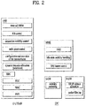
- FIG. 2 is a diagram exemplarily illustrating architectures of a typical E-UTRAN and EPC.
- an eNodeB may perform routing to a gateway, scheduling transmission of a paging message, scheduling and transmission of a broadcast channel (BCH), dynamic allocation of resources to a UE on uplink and downlink, configuration and provision of eNodeB measurement, radio bearer control, radio admission control, and connection mobility control.
- RRC radio resource control
- BCH broadcast channel
- paging generation LTE_IDLE state management
- ciphering of the user plane ciphering of the user plane
- SAE bearer control and ciphering and integrity protection of NAS signaling.
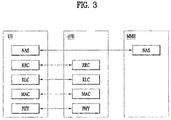
- FIG. 3 is a diagram exemplarily illustrating the structure of a radio interface protocol in a control plane between a UE and an eNB
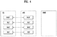
- FIG. 4 is a diagram exemplarily illustrating the structure of a radio interface protocol in a user plane between the UE and the eNB.
- the radio interface protocol is based on the 3GPP wireless access network standard.
- the radio interface protocol horizontally includes a physical layer, a data link layer, and a networking layer.
- the radio interface protocol is divided into a user plane for transmission of data information and a control plane for delivering control signaling which are arranged vertically.
- the protocol layers may be classified into a first layer (L1), a second layer (L2), and a third layer (L3) based on the three sublayers of the open system interconnection (OSI) model that is well known in the communication system.
- OSI open system interconnection
- the physical layer which is the first layer, provides an information transfer service using a physical channel.
- the physical channel layer is connected to a medium access control (MAC) layer, which is a higher layer of the physical layer, through a transport channel.
- MAC medium access control
- Data is transferred between the physical layer and the MAC layer through the transport channel. Transfer of data between different physical layers, i.e., a physical layer of a transmitter and a physical layer of a receiver is performed through the physical channel.
- the physical channel consists of a plurality of subframes in the time domain and a plurality of subcarriers in the frequency domain.
- One subframe consists of a plurality of symbols in the time domain and a plurality of subcarriers.
- One subframe consists of a plurality of resource blocks.
- One resource block consists of a plurality of symbols and a plurality of subcarriers.
- a Transmission Time Interval (TTI) a unit time for data transmission, is 1 ms, which corresponds to one subframe.
- the physical channels present in the physical layers of the transmitter and the receiver may be divided into data channels corresponding to Physical Downlink Shared Channel (PDSCH) and Physical Uplink Shared Channel (PUSCH) and control channels corresponding to Physical Downlink Control Channel (PDCCH), Physical Control Format Indicator Channel (PCFICH), Physical Hybrid-ARQ Indicator Channel (PHICH) and Physical Uplink Control Channel (PUCCH).
- PDSCH Physical Downlink Shared Channel
- PUSCH Physical Uplink Shared Channel
- PCFICH Physical Control Format Indicator Channel
- PHICH Physical Hybrid-ARQ Indicator Channel
- PUCCH Physical Uplink Control Channel
- the second layer includes various layers.
- the MAC layer in the second layer serves to map various logical channels to various transport channels and also serves to map various logical channels to one transport channel.
- the MAC layer is connected with an RLC layer, which is a higher layer, through a logical channel.
- the logical channel is broadly divided into a control channel for transmission of information of the control plane and a traffic channel for transmission of information of the user plane according to the types of transmitted information.
- the radio link control (RLC) layer in the second layer serves to segment and concatenate data received from a higher layer to adjust the size of data such that the size is suitable for a lower layer to transmit the data in a radio interface.
- RLC radio link control
- the Packet Data Convergence Protocol (PDCP) layer in the second layer performs a header compression function of reducing the size of an IP packet header which has a relatively large size and contains unnecessary control information, in order to efficiently transmit an IP packet such as an IPv4 or IPv6 packet in a radio interface having a narrow bandwidth.
- the PDCP layer also performs a security function, which consists of ciphering for preventing a third party from monitoring data and integrity protection for preventing data manipulation by a third party.
- the Radio Resource Control (RRC) layer which is located at the uppermost part of the third layer, is defined only in the control plane, and serves to configure radio bearers (RBs) and control a logical channel, a transport channel, and a physical channel in relation to reconfiguration and release operations.
- the RB represents a service provided by the second layer to ensure data transfer between a UE and the E-UTRAN.
- the UE If an RRC connection is established between the RRC layer of the UE and the RRC layer of a wireless network, the UE is in the RRC Connected mode. Otherwise, the UE is in the RRC Idle mode.
- the RRC state refers to a state in which the RRC of the UE is or is not logically connected with the RRC of the E-UTRAN.
- the RRC state of the UE having logical connection with the RRC of the E-UTRAN is referred to as an RRC_CONNECTED state.
- the RRC state of the UE which does not have logical connection with the RRC of the E-UTRAN is referred to as an RRC_IDLE state.
- a UE in the RRC_CONNECTED state has RRC connection, and thus the E-UTRAN may recognize presence of the UE in a cell unit. Accordingly, the UE may be efficiently controlled.
- the E-UTRAN cannot recognize presence of a UE which is in the RRC_IDLE state.
- the UE in the RRC_IDLE state is managed by a core network in a tracking area (TA) which is an area unit larger than the cell. That is, for the UE in the RRC_IDLE state, only presence or absence of the UE is recognized in an area unit larger than the cell.
- TA tracking area
- a TA is distinguished from another TA by a tracking area identity (TAI) thereof.
- a UE may configure the TAI through a tracking area code (TAC), which is information broadcast from a cell.
- TAI tracking area identity
- the UE When the user initially turns on the UE, the UE searches for a proper cell first. Then, the UE establishes RRC connection in the cell and registers information thereabout in the core network. Thereafter, the UE stays in the RRC_IDLE state. When necessary, the UE staying in the RRC_IDLE state selects a cell (again) and checks system information or paging information. This operation is called camping on a cell. Only when the UE staying in the RRC IDLE state needs to establish RRC connection, does the UE establish RRC connection with the RRC layer of the E-UTRAN through the RRC connection procedure and transition to the RRC_CONNECTED state. The UE staying in the RRC_IDLE state needs to establish RRC connection in many cases. For example, the cases may include an attempt of a user to make a phone call, an attempt to transmit data, or transmission of a response message after reception of a paging message from the E-UTRAN.
- the non-access stratum (NAS) layer positioned over the RRC layer performs functions such as session management and mobility management.
- the NAS forms the highest stratum of the control plane between a UE and an MME.
- the main functions of the protocols that are part of the NAS are to support mobility of the UE and session management procedures for establishing and maintaining IP connectivity between the UE and a P-GW.
- the NAS security is an additional function of the NAS that provides services to the NAS protocols, for example, integrity protection and ciphering of NAS signaling messages.
- EMM EPS mobility management
- ESM elementary procedures for EPS session management
- complete NAS transactions consist of specific sequences of elementary procedures.
- the main function of a mobility management sublayer is to support the mobility of the UE such as informing the network of its current location and providing user identity confidentiality.
- Another function of the mobility management sublayer is to provide connection management services to a session management (SM) sublayer and a short message services (SMS) entity of a connection management (CM) sublayer. All EMM procedures can be performed only when a NAS signaling connection has been established between the UE and network. Otherwise, the EMM sublayer initiates the establishment of the NAS signaling connection.
- SM session management
- SMS short message services
- the EMM procedures can be classified into the following three types: EMM common procedures; EMM specific procedures; and EMM connection management procedures (S1 mode only).
- the EMM common procedures can always be initiated while the NAS signaling connection exists.
- only one UE initiated EMM specific procedure can be running at any time.
- the EMM specific procedures include attach, detach, tracking area update, etc.
- the EMM connection management procedures include service request, paging request, transport of NAS messages, and generic transport of NAS messages.
- the ESM EPS Session Management
- the ESM belongs to the NAS layer performs functions such as default bearer management and dedicated bearer management to control a UE to use a PS service from a network.
- the main function of an ESM sublayer is to support EPS bearer context handling in the UE and MME.
- the ESM includes a procedure(s) for the activation, deactivation and modification of EPS bearer contexts and a procedure(s) for the request for resources (IP connectivity to a PDN or dedicated bearer resources) by the UE.
- the default EPS bearer resource may be allocated by the network.
- the network allocates an available IP to the UE to allow the UE to use a data service.
- the network also allocates QoS of a default bearer to the UE.
- LTE supports two kinds of bearers.
- One bearer is a bearer having characteristics of guaranteed bit rate (GBR) QoS for guaranteeing a specific bandwidth for transmission and reception of data, and the other bearer is a non-GBR bearer which has characteristics of best effort QoS without guaranteeing a bandwidth.
- the default bearer is assigned to a non-GBR bearer.
- the dedicated bearer may be assigned a bearer having QoS characteristics of GBR or non-GBR.
- a bearer allocated to the UE by the network is referred to as an evolved packet service (EPS) bearer. When the EPS bearer is allocated to the UE, the network assigns one ID. This ID is called an EPS bearer ID.
- One EPS bearer has QoS characteristics of a maximum bit rate (MBR) and/or a guaranteed
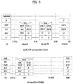
- FIG. 5 illustrates LTE protocol stacks for a user plane and a control plane.
- FIG. 5(a) illustrates user plane protocol stacks over UE-eNB-SGW-PGW-PDN and
- FIG. 5(b) illustrates control plane protocol stacks over UE-eNB-MME-SGW-PGW. Functions of key layers of the protocol stacks will now be briefly described below.
- a GTP-U protocol is used to forward user IP packets over an S1-U/S5/X2 interface. If a GTP tunnel is established to forward data during LTE handover, an end marker packet is transferred to the GTP tunnel as the last packet.
- an S1-AP protocol is applied to an S1-MME interface.
- the SlAP protocol supports functions such as S1 interface management, E-RAB management, NAS signaling delivery, and UE context management.
- the S1-AP protocol transfers an initial UE context to the eNB in order to set up E-RAB(s) and then manages modification or release of the UE context.
- a GTP-C protocol is applied to S11/S5 interfaces.
- the GTP-C protocol supports exchange of control information for generation, modification, and termination of GTP tunnel(s).
- the GTP-C protocol generates data forwarding tunnels in the case of LTE handover.
- a description of the protocol stacks and interfaces illustrated in FIGs. 3 and 4 is applicable to the same protocol stacks and interfaces illustrated in FIG. 5 .
- FIG. 6 is a flowchart illustrating a random access procedure in 3GPP LTE.
- the random access procedure is used for a UE to obtain UL synchronization with a base station or to be assigned a UL radio resource.
- the UE receives a root index and a physical random access channel (PRACH) configuration index from an eNB.
- Each cell has 64 candidate random access preambles defined by a Zadoff-Chu (ZC) sequence.
- the root index is a logical index used for the UE to generate 64 candidate random access preambles.
- Transmission of a random access preamble is limited to a specific time and frequency resources for each cell.
- the PRACH configuration index indicates a specific subframe and preamble format in which transmission of the random access preamble is possible.
- the random access procedure in particular, a contention-based random access procedure, includes the following three steps. Messages transmitted in the following steps 1, 2, and 3 are referred to as msg1, msg2, and msg4, respectively.
- FIG. 7 illustrates a connection procedure in a radio resource control (RRC) layer.
- RRC radio resource control
- the RRC state is set according to whether or not RRC connection is established.
- An RRC state indicates whether or not an entity of the RRC layer of a UE has logical connection with an entity of the RRC layer of an eNB.
- An RRC state in which the entity of the RRC layer of the UE is logically connected with the entity of the RRC layer of the eNB is called an RRC connected state.
- An RRC state in which the entity of the RRC layer of the UE is not logically connected with the entity of the RRC layer of the eNB is called an RRC idle state.
- a UE in the connected state has RRC connection, and thus the E-UTRAN may recognize presence of the UE in a cell unit. Accordingly, the UE may be efficiently controlled.
- the eNB cannot recognize presence of a UE which is in the idle state.
- the UE in the idle state is managed by the core network in a tracking area unit which is an area unit larger than the cell.
- the tracking area is a unit of a set of cells. That is, for the UE which is in the idle state, only presence or absence of the UE is recognized in a larger area unit.
- the UE in the idle state In order for the UE in the idle state to be provided with a usual mobile communication service such as a voice service and a data service, the UE should transition to the connected state.
- the UE When the user initially turns on the UE, the UE searches for a proper cell first, and then stays in the idle state. Only when the UE staying in the idle state needs to establish RRC connection, does the UE establish RRC connection with the RRC layer of the eNB through the RRC connection procedure and then transition to the RRC connected state.
- the UE staying in the idle state needs to establish RRC connection in many cases.
- the cases may include an attempt of a user to make a phone call, an attempt to transmit data, or transmission of a response message after reception of a paging message from the E-UTRAN.
- the RRC connection procedure is broadly divided into transmission of an RRC connection request message from the UE to the eNB, transmission of an RRC connection setup message from the eNB to the UE, and transmission of an RRC connection setup complete message from the UE to eNB, which are described in detail below with reference to FIG. 7 .
- MTC machine type communication
- MTC refers to exchange of information between a machine and an eNB without involving persons or with minimal human intervention.
- MTC may be used for data communication for measurement/sensing/reporting such as meter reading, water level measurement, use of a surveillance camera, inventory reporting of a vending machine, etc. and may also be used for automatic application or firmware update processes for a plurality of UEs.
- the amount of transmission data is small and UL/DL data transmission or reception (hereinafter, transmission/reception) occurs occasionally.
- MTC UEs MTC UEs
- MTC UEs MTC UEs
- the channel environment thereof remains substantially the same. If an MTC UE is used for metering, reading of a meter, surveillance, and the like, the MTC UE is very likely to be located in a place such as a basement, a warehouse, and mountain regions which the coverage of a typical eNB does not reach. In consideration of the purposes of the MTC UE, it is better for a signal for the MTC UE to have wider coverage than the signal for the conventional UE (hereinafter, a legacy UE).
- the IoT means internetworking of physical devices, connected devices, smart devices, buildings, and other items with electronics, software, sensors, actuators, and network connectivity that enable these objects to collect and exchange data.
- the IoT refers to a network of physical objects, machines, people, and other devices that enable connectivity and communication for the purpose of exchanging data for intelligent applications and services.
- the IoT allows objects to be sensed and controlled remotely through existing network infrastructures, thereby providing opportunities for the direct integration between the physical and digital worlds, which result in improving efficiency, accuracy and economic benefits.
- the IoT using the 3GPP technology is referred to as cellular IoT (CIoT).
- the CIoT that transmits/receives IoT signals using a narrowband e.g., a frequency band of about 200 kHz
- NB-IoT narrowband
- the CIoT is used to monitor traffic transmitted over a relatively long period, e.g., from a few decades to a year (e.g., smoke alarm detection, power failure notification from smart meters, tamper notification, smart utility (gas/water/electricity) metering reports, software patches/updates, etc.) and support 'IoT' devices characterized as ultra-low complexity, power limitation and low data rates.
- a connection with the network should be established for transmitting data to a UE in EMM-Idle mode.
- the UE should successfully complete the service request procedure illustrated in FIG. 8 , but it is not suitable for the CIoT that requires optimized power consumption for the low data rate.
- two types of optimization User Plane CIoT EPS optimization and Control Plane CIoT EPS optimization has been defined for the CIoT in the EPS.
- the User Plane CIoT EPS optimization and Control Plane CIoT optimization can be referred to U-plane CIoT EPS optimization and C-plane CIoT EPS optimization, respectively.
- the Control Plane CIoT EPS optimization is signaling optimization capable of efficient transport of user data (IP or non-IP or SMS) on the control plane.
- IP or non-IP or SMS user data
- the UE and MME may transfer IP or non-IP data through NAS signaling depending on data types selected for a PDN connection supported at PDN connection establishment.
- the Control Plane CIoT EPS optimization can be achieved by using NAS transport capabilities of RRC and S1-AP protocols and data transfer through GTP (Evolved General Packet Radio Service (GPRS) Tunneling Protocol) tunnels between an MME and an S-GW and between an S-GW and a P-GW.
- GTP Evolved General Packet Radio Service
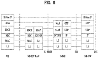
- FIG. 8 illustrates user plane protocol stacks between a UE and a P-GW in accordance with the Control Plane CIoT EPS optimization.
- GTP-u is a protocol which tunnels user data between the MME and S-GW as well as between the S-GW and P-GW in the backbone network.
- GTP encapsulates all end user IP packets.
- UDP/IP are the backbone network protocols used for routing user data and control signaling.
- NAS is the non-access stratum layer used to carry data between the UE and MME and may include header compression and security functions for user plane IP data.
- the CIoT network or technology mainly provides communication services optimized for the IoT UE in terms of the core network, and the NB-IoT (narrowband Internet of Thing) network or technology optimizes the radio interface of the existing LTE technology for IoT.
- NB-IoT narrowband Internet of Thing
- the NB-IoT is a wireless technology that provides IoT services using a narrowband frequency of about 200 kHz. Compared to the conventional LTE technology using the minimum frequency band of about 1.25 MHz, the NB-IoT uses a very small frequency band. Therefore, the NB-IoT minimizes the processing power and power consumption of the UE.
- the CIoT is a technology that minimizes the power consumption of the UE through the C-plane solution (that is, data is processed by the MME) or the U-plane solution (that is, even if the UE is in the RRC_IDLE state or a similar state, the UE and eNB maintains the context and use the context for the next connection in order to prevent the power consumption issue of the UE, which is caused because a number of messages are exchanged during the conventional attach or service request procedure.
- the NB-IoT radio technology and CIoT technology can be applied separately. That is, even if the NB-IoT radio technology is not used, it is possible to apply the CIoT technology through the conventional LTE radio network.
- the CIoT technology can be applied to UEs that cannot use the NB-IoT radio technology, for example, UEs already released with the LTE radio technology only.
- conventional LTE radio technology based cells can support conventional LTE UEs such as smart phones while simultaneously supporting IoT UEs.
- the S1 mode means that the UE uses the S1 interface between the radio access network and core network.
- the S1 mode the UE accesses network services via the E-UTRAN.
- the S1 mode is divided into the WB-S1 mode and the NB-S1 mode according to the current radio access network.
- the system In the multi-access system, if the current serving E-UTRA provides the S1 mode in accordance with the NB-IoT, the system is considered to operate in the NB-S1 mode (see 3GPP TS 24.301, 3GPP TS 36.300, 3GPP TS 36.331, and 3GPP TS 36.306). In addition, in the multi-access system, if the system operates in the S1 mode rather than the NB-S1 mode, the system is considered to operate in the WB-S1 mode. In other words, the CIoT mode includes the WB-S1 and NB-S1 modes, and the NB-IoT corresponds to the NB-S1 mode. Except the NB-IoT, the rest of the CIoT except including the conventional LTE may correspond to the WB-S1 mode.
- a UE in the idle state When new traffic occurs, a UE in the idle state performs a service request procedure to transition to the active state capable of transmitting/receiving traffic. If the UE has traffic to be transmitted or the network has traffic to be transmitted to the UE in a state in which the UE is registered in the network but the S1 connection is released due to traffic deactivation, that is, when the UE is in the EMM-Registered state but in the ECM-Idle state, the UE send the service request to the network. Upon successfully completing the service request process, the UE transitions to the ECM-Connected state and configures the ECM connection (RRC connection + S1 signaling connection) on the control plane and E-RAB (DRB and an S1 bearer) on the user plane.
- ECM connection RRC connection + S1 signaling connection
- the UE transmits/receives traffic. If the network desires to send traffic to a UE in the ECM-Idle state, the network informs the UE, through a paging message, that there is traffic to be transmitted so that the UE can send the service request. Details of the network-triggered service request procedure can be found in section 5.3.4.3 of 3GPP TS 23.401.
- the UE When a UE has traffic to be transmitted, the UE send the RRC connection request to the eNB through the random access procedure including steps 1) to 3) of FIG. 7 . If the eNB accepts the RRC connection request from the UE, the eNB transmit the RRC connection setup message. After receiving the RRC connection setup message, the UE transmits the RRC connection setup complete message to the eNB by including the service request in the message. Details of the UE-triggered service request procedure can be found in section 5.3.4.1 of 3GPP TS 23.401.
- FIG. 9 shows a mobile originated data transfer procedure in the Control Plane CIoT EPS optimization.
- the S-GW shall send a Modify Bearer Request message with PDN Charging Pause Stop Indication to inform the PDN GW that the charging is no longer paused.
- Other IEs are not included in this message.
- Initial NAS message may include: ATTACH REQUEST; DETACH REQUEST; TRACKING AREA UPDATE REQUEST; SERVICE REQUEST; and EXTENDED SERVICE REQUEST.
- the SERVICE REQUEST message is sent by the UE to the network to request the establishment of a NAS signaling connection and radio and S1 bearers.
- the EXTENDED SERVICE REQUEST message is sent by the UE to the network to initiate a CS fallback or 1xCS fallback call or respond to a mobile terminated CS fallback or 1xCS fallback request from the network; or to request the establishment of a NAS signaling connection and the radio and S1 bearers for packet services if the UE needs to provide additional information that cannot be provided via the SERVICE REQUEST message.
- the NAS message in step 1 of FIG. 9 may correspond to the SERVICE REQUEST message, and it is encapsulated in the RRC CONNECTION SETUP COMPLETE message.
- the purpose of the service request procedure is to transfer the EMM mode from EMM-IDLE to EMM-CONNECTED mode. If the UE is not using the Control Plane CIoT EPS optimization, which will be described later, the service request procedure also establishes the radio and S1 bearers when user data or signaling is sent. If the UE is using the Control Plane CIoT EPS optimization, the service request procedure may be used for UE-initiated transfer of CIoT data.
- the service request procedure is used in the following cases: when the network has downlink signaling pending; when the UE has uplink signaling pending; when the UE or the network has user data pending and the UE is in the EMM-IDLE mode; and when the UE in the EMM-IDLE or EMM-CONNECTED mode has requested to perform mobile originating/terminating CS fallback or 1xCS fallback.
- the service request procedure is initiated by the UE, but for the downlink transfer of signaling, cdma2000® signaling or the EMM-IDLE mode, the trigger is given by the network by means of the paging procedure.
- the UE may invoke the service request procedure in the following cases:
- the network activates a default EPS bearer context.
- the network can activate one or several dedicated EPS bearer contexts in parallel for IP PDN type PDN connections.
- the EPS session management message for the default EPS bearer context activation may be transmitted in an information element in the EPS mobility management message.
- the UE and the network execute the attach procedure, the default EPS bearer context activation procedure, and the dedicated EPS bearer context activation procedure in parallel.
- the UE and network should complete the combined default EPS bearer context activation procedure and the attach procedure before the dedicated EPS bearer context activation procedure is completed. If the UE or MME does not support the EMM-REGISTERED state with no PDN connection, the success of the attach procedure is dependent on the success of the default EPS bearer context activation procedure. If the attach procedure fails, then the ESM procedure also fails.
- EMM messages include the following types: attach accept; attach reject; attach reject; attach request; authentication failure; authentication reject; authentication request; authentication response; CS service notification; detach accept; detach reject; downlink NAS transport; EMM information; EMM status; extended service request; service request; service reject; tracking area update accept; tracking area update complete; tracking area update reject; tacking area update request; uplink NAS transport; downlink generic NAS transport; and uplink NAS transport.
- ESM messages include the following messages: activate dedicated EPS bearer context accept; activate dedicated EPS bearer context reject; activate dedicated EPS bearer context request; activate default EPS bearer context accept; activate default EPS bearer context reject; activate default EPS bearer context request; bearer resource allocation reject; bearer resource allocation request; bearer resource modification reject; bearer resource modification request; deactivate EPS bearer context request; deactivate EPS bearer context accept; ESM information request; ESM information response; and ESM status. Details of the currently defined EMM and ESM messages can be found in 3GPP TS 24.301 V13.4.0.
- proposal 1 proposes to use a new NAS message
- proposal 2 proposes to modify and use an existing EXTENDED SERVICE REQUEST message.
- small data transfer methods according to proposals 1 and 2 will be described.
- the purpose of the ESM message container IE is to enable piggyback transfer of a single ESM message in the EMM message.
- Proposals 1 and 2 are the same in that in the EMM-IDLE mode, EMM messages are transmitted and message containers are included in the corresponding EMM messages. However, messages, which carry data, in the message containers are different in the two proposals.
- proposal 1 a new ESM message (e.g., ESM DATA TRANSPORT message) is included in the message container, but in proposal 2, an existing EMM message (e.g., UPLINK GENERIC NAS TRANSPORT message) is reused.
- the existing ESM message is included instead of the new ESM message.
- the UE in the EMM-IDLE mode performs an EMM procedure ((data) service request procedure) to transmit the EMM message including small data.
- EMM procedure (data) service request procedure) to transmit the EMM message including small data.
- the UE determines that the service request procedure has been successfully completed and enters the EMM-CONNECTED mode.
- the UE For case b among cases where the UE activates the service request procedure, if the UE is attached for EPS services with the CP-CIoT EPS optimization (that is, if the UE is using the CP-CIoT EPS optimization services), the UE initiates CIoT data transfer by sending the EXTENDED SERVICE REQUEST message with the service type set to "mobile originating CIoT data transfer".
- the network receives the EXTENDED SERVICE REQUEST message, the UE considers that the service request is successfully completed.
- the UE determines the success of the service request procedure based on the conditions of lower layers (e.g., AS layer). For example, in proposal 1, if the RRC connection is successfully established, it is determined that the EMM procedure is successful. On the other hand, in proposal 2, if the AS layer (e.g., RRC layer), which is one of the lower layers, indicates that the NAS message (e.g., EXTENDED SERVICE REQUEST message) is successfully transmitted, it is determined that the EMM procedure is successfully performed.
- the AS layer e.g., RRC layer
- the NAS message e.g., EXTENDED SERVICE REQUEST message
- the UPLINK GENERIC NAS TRANSPORT message is an EMM message and used to transfer data such as a location service (LCS), and the UPLINK NAS TRANSPORT message is used to transmit an SMS.
- EMM messages can be sent only when the UE is in the EMM-CONNECTED state. Specifically, a timer for checking whether a corresponding NAS (EMM) message is successfully transmitted does not have to be considered and a case where the MME rejects the corresponding NAS message has not been considered.
- an EMM message contains small data and is similar to the existing UPLINK GENERIC NAS TRANSPORT message.
- the EMM message is different from the existing UPLINK GENERIC NAS TRANSPORT message in that it has the features of the initial NAS message such as ATTACH, TRACKING AREA UPDATE, SERVICE REQUEST. Due to this difference, in some cases, the MME should reject the corresponding EMM message. For example, there may occur a case where the MME should reject the service request by the EMM message.
- the MME accepts the EMM message for the Control Plane optimization instead of rejecting it, it means that the network does not perform procedures for checking UEs and the services which the UEs are registered in. In this case, if a network problem such as congestion occurs, there is no means of solving such a problem. In addition, if these UEs coexist with other legacy UEs, the legacy UEs may experience reverse discrimination.
- the network does not determine whether the small data is received. Thus, it is the best way that the UE performs transmission without any error via a radio interface. If the UE correctly transmits small data in the radio interface, the UE can consider that the transmission of the small data is successful.
- the EMM message mentioned in both proposals 1 and 2 has the two objects: mobility management and small data transfer.
- proposal 1 when the RRC connection is successfully established, the UE determines that a corresponding EMM procedure has been successfully completed.
- the lower layer e.g., RRC layer
- the EXTENDED SERVICE REQUEST e.g., EXTENDED SERVICE REQUEST message
- the eNB may fail to transfer it to the MME. Further, even when the MME successfully receives the EMM message, the MME may reject the corresponding EMM message or not respond due to its own problem. In other words, in both proposals 1 and 2, since the EMM message with small data is considered only in terms of the small data, the success or failure of the EMM message (except the small data), that is, the EMM procedure based on the EMM message is not separately considered only if it is checked that the EMM message with the small data has been successfully transmitted from the RRC layer.
- the success of the EMM procedure is determined based on only the small data transfer regardless of whether the EMM message is successfully transmitted.
- the network e.g., MME
- the MME sends no response for the EMM message to the UE, the UE cannot determine whether the EMM message is correctly delivered to the network.
- the UE when the UE transmits multiple NAS PDUs, if the UE transmits an initial NAS message (that is, EMM message) and the lower layer indicates that the initial NAS message is successfully transmitted, the UE determines that the initial NAS message is successfully delivered to the MME and the MME accepts the initial NAS message. Thereafter, the UE enters the EMM-CONNECTED state.
- the second or later NAS messages correspond to new ESM messages or UPLINK GENERIC NAS TRANSPORT messages rather than initial NAS messages.
- the initial NAS message is not successfully delivered to the MME or if, upon receiving the initial NAS message, the MME rejects it, the second NAS message may not be successfully delivered to the MME.
- the EMM message used for the Control Plane optimization has the two objects: mobility management and small data transfer.
- the success of the EMM procedure is determined based on whether small data is successfully transferred without consideration of whether the EMM message is successfully transmitted.
- the success of the EMM procedure should be determined by considering both the two objects: mobility management and data transfer.
- the eNB when the service request procedure is successfully performed, the eNB performs the procedure for establishing a DRB (data radio bearer). And, if the DRB establishment procedure is successfully completed, the access stratum (AS) layer of the UE informs the NAS layer that the user plane bearer has been established.
- DRB data radio bearer
- the NAS layer of the UE recognizes that the service request procedure has been successfully performed.
- the UE e.g., NAS layer of the UE
- the UE cannot determine whether the EMM message has been successfully delivered in the EMM-IDLE mode.
- inventions 1-1, 1-2, and 1-3 methods for determining whether the EMM message, which is transmitted together with the first NAS PDU, is successfully transmitted are described. Inventions 1-1, 1-2, and 1-3 can be applied together or independently.
- the initial NAS message containing the first NAS PDU, which is transmitted from the UE is referred to as an EMM REQUEST message in order to distinguish it from the EMM message transmitted from the network.
- the INITIAL UE message containing the NAS PDU that includes data may correspond to the DATA SERVICE REQUEST message (see proposal 1) or the EXTENDED SERVICE REQUEST message (see proposal 2).
- the EMM REQUEST message according to the present invention can be called other names rather than the DATA SERVICE REQUEST message or EXTENDED SERVICE REQUEST message.
- the EMM REQUEST message may be the SERVICE REQUEST message transmitted from the UE to the network when the UE uses the Control Plane CIoT EPS optimization.
- timer T31xx may be timer T3417ext.
- 'operation in which the MME accepts/rejects the INITIAL UE message' may be performed by the NAS layer of the MME.
- timers T31ab, T31xx, and T31xy are EMM timers of the UE that initiates the EMM request. If the same functions and operations as described in the present invention are applied, the corresponding timers can be called as other names rather than T31ab, T31xx, and T31xy.
- invention 1-1 proposes to introduce the EMM message for service acceptance in order to response the EMM request for data transfer in accordance with the Control Plane CIoT EPS optimization.
- the UE and MME can operate as follows.
- the UE When the UE (NAS layer) transmits the EMM REQUEST message, the UE (NAS layer) starts timer T31ab at the same time.
- the UE may consider that the EMM REQUEST message is successfully transmitted.
- the UE fails to receive any response (e.g., ACCEPT or REJECT message) to the EMM REQUEST message, which was transmitted by the corresponding UE, from the network before the expiration of timer T31ab after starting timer 31ab, the UE retransmits the EMM message including the NAS PDU.
- the MME When the MME receives the EMM REQUEST message for the mobile originated data transport in the Control Plane CIoT EPS optimization from the UE in the EMM-IDLE state and accepts the EMM REQUEST message, the MME transmits the ACCEPT message (EMM message) in response to the EMM REQUEST message to the UE.
- EMM message ACCEPT message
- the UE When receiving the ACCEPT message, the UE recognizes that the EMM REQUEST message has been successfully transmitted. That is, upon receiving the ACCEPT message, the UE considers/treats that the corresponding EMM procedure has been successfully completed. In this case, the UE switches its states to the EMM-CONNECTED state.
- invention 1-1 can be applied to all cases where the mobile originated data is transported in accordance with the Control Plane CIoT EPS optimization. Alternatively, invention 1-1 can be limitedly applied only when the UE transmits multiple NAS PDUs in accordance with the Control Plane CIoT EPS optimization.
- invention 1-1 is applied in the case where the multiple NAS PDUs are transmitted, if the UE receives the ACCEPT message in response to the NAS message transmitted in the EMM-IDLE mode, the UE recognizes that the current mode is the EMM-CONNECTED mode, that is, the UE considers that its current mode switches to the EMM-CONNECTED mode.
- the UE may transmit the second NAS message.
- a method for transmitting the second and later NAS messages will be described in detail in the section of ⁇ The method for transmitting second and later NAS PDUs when multiple NAS PDUs are transmitted>.
- ⁇ Invention 1-2 when the network accepts an EMM REQUEST message, the network transmits an ACCEPT message via S1AP and radio interfaces (that is, the network informs acceptance of the EMM REQUEST message via S1-AP and RRC messages).>
- the ACCEPT message in response to the EMM REQUEST message is configured in the form of a NAS message
- the ACCEPT message in response to the EMM REQUEST message is configured in the form of S1-AP and RRC messages including acceptance indication.
- the MME when the MME receives an INITIAL UE message containing a NAS PDU that includes data and has no signaling or user data to send in downlink, the MME transmits a CONNECTION ESTABLISHMENT INDICATION message to the eNB.
- the MME allocates a unique MME UE S1AP ID to be used for the UE and includes the ID in the CONNECTION ESTABLISHMENT INDICATION message.
- Invention 1-2 is proposed based on such a connection establishment indication procedure.
- FIG. 10 illustrates a method according to the present invention in which the network informs the UE that the EMM procedure is successful.
- FIG. 10 shows a method by which network nodes (MME and eNB) informs the UE of the success of the EMM procedure when the MME receives the INITIAL UE message containing the NAS PDU which includes data and has no signaling or user data to send in downlink.
- MME and eNB network nodes
- step 3 if the MME receives the INITIAL UE message and has downlink signaling or user data to transmit to the UE, the network node may inform the UE of the success of the EMM procedure according to invention 1-3, which will be described later.
- the eNB, MME, and UE may respectively operate as follows.
- the eNB If the eNB receives the connection establishment indication from the MME in step 3 of FIG. 10 , the eNB recognizes that the INITIAL UE message containing the NAS PDU that includes the data, which had been transmitted from the UE, was successfully delivered to the MME and the MME accepted the INITIAL UE message and then forwards the connection establishment indication to the UE in step 4 of FIG. 10 .
- the RRC message used for transmitting the connection establishment indication may be an existing RRC message or a new RRC message which is defined for transmitting the connection establishment indication.
- the AS layer of the UE Upon receiving the connection establishment indication, the AS layer of the UE transmits an indication for connection establishment for the control plane to the higher layer (e.g., NAS layer).
- the NAS layer of the UE recognizes (determines or considers) that the INITIAL UE message containing the NAS PDU which includes the data, which had been transmitted in step 1 of FIG. 10 , was successfully delivered to the MME and the MME accepted the initial NAS message. Thereafter, the NAS layer of the UE switches the current state to the EMM-CONNECTED state. If there is a NAS PDU including additional data to be transmitted, the NAS PDU may be transmitted in a NAS message. In this case, the NAS message is the NAS message transmitted in the EMM-CONNECTED state rather than the INITIAL UE message.
- FIG. 11 illustrates a method by which the network node informs the UE that the EMM procedure is rejected.
- FIG. 11 shows how network nodes (MME and eNB) informs the UE of the failure of the EMM procedure when the network (e.g., MME) rejects the EMM request (e.g., service request for data transport in the Control Plane CIoT EPS optimization).
- FIG. 12 illustrates the operation of the UE's NAS layer when the network accepts or rejects the EMM request.
- the upper figure of FIG. 12 shows a case where the network accepts the EMM request
- the lower figure of FIG. 12 shows a case where the network rejects the EMM request.
- AS means an access stratum.
- the UE transmits an INITIAL UE message including a NAS PDU that includes data, that is, an EMM REQUEST message for the Control Plane CIoT EPS optimization.
- the NAS layer of the UE starts timer T31xx.
- the NAS layer of the UE stops timer T31xx and transitions to the EMM-CONNECTED state.
- the UE receives an EMM REJECT message before the expiration of timer T31xx, the UE stops timer T31xx and operates based on a cause included in the EMM REJECT message (details can be found in section 8.2.24 "Service Reject" of 3GPP TS 24.301).
- ⁇ Invention 1-3 A method for determining the success or failure of an EMM REQUEST message with no ACCEPT message>
- FIG. 13 illustrates another method according to the present invention in which the network node informs the UE that the EMM procedure is successful.
- FIG. 13 shows another method by the network nodes (MME and eNB) informs the UE of the success of the EMM procedure when the MME receives the INITIAL UE message containing the NAS PDU which includes data and has no signaling or user data to send in downlink.
- the NAS layer of the UE may know whether the EMM request is successful with no EMM ACCEPT message unlike FIG. 10 .
- AS means an access stratum.
- the UE may determine whether its EMM REQUEST message is successfully delivered or not as follows.
- ACK/NACK acknowledgement/NACK
- the UE when transmitting the EMM REQUEST message, the UE (NAS layer) simultaneously starts timer T31xx.
- the UE may consider that the EMM REQUEST message is successfully transmitted. If the UE fails to receive the indication indicating that the RRC connection is released or any response (e.g., rejection) from the network before the expiration of timer T31xx, the UE retransmits the EMM REQUEST message including a NAS PDU.
- the NAS PDU may be the same as the previous NAS PDU or a new NAS PDU different from the previous NAS PDU according to whether the small data is successfully transmitted. If the operation which will be described in the section of ⁇ The operation depending on whether the EMM message and small data are successfully transmitted>, is not applied together, the UE cannot know whether the small data is successfully transmitted. Thus, the UE may transmit the same NAS PDU as the previously transmitted NAS PDU.
- the UE when the UE (NAS layer) receives a specific cause (for example, data is successfully delivered) together with the indication indicating that the RRC connection is released, the UE may consider that the EMM REQEUST message is successfully transmitted.
- the UE should distinguish between the RRC connection release and the conventional RRC connection release, which is triggered by the eNB when an inactivity timer expires (see steps 13 and 14 of FIG. 9 ).
- a specific release cause for example, 'Data Delivered' may be used.
- ACK/NACK ACK/NACK
- the UE when transmitting the EMM REQUEST message, the UE (NAS layer) simultaneously starts timer T31xx. If the UE (NAS layer) successfully receives downlink data before expiration of timer T31xx, the UE (NAS layer) may consider that the EMM REQUEST message is successfully transmitted.
- the downlink data may be a response to uplink data or downlink data unrelated to uplink.
- the UE If the UE fails to receive downlink data, a response (e.g., ACK/NACK) to the uplink data transmitted in the EMM REQUEST message, or a response (e.g., rejection) to the EMM REQUEST message from the network before the expiration of timer T31xx, the UE retransmits the EMM REQUEST message including a NAS PDU. If downlink data corresponds to the response (ACK or NACK), which the UE (NAS layer) expects to receive in response to the NAS PDU transmitted in the EMM REQUEST message, the UE may consider that the EMM REQUEST message is successfully transmitted. In this case, the higher layer (e.g., application layer) of the UE may inform the NAS layer of the UE that the downlink data corresponds to the response (ACK or NACK) to the NAS PDU transmitted in the EMM REQUEST message.
- the higher layer e.g., application layer
- the UE transmits an INITIAL UE message containing a NAS PDU which includes data, i.e., an EMM message for the Control Plane CIoT optimization.
- the UE starts timer T31xx at the same time with transmission of the INITIAL UE message.
- the lower layers e.g., AS layer
- the NAS layer of the UE recognizes/considers that the INITIAL UE message including the NAS PDU that contains the data has been successfully transmitted to the MME and the MME has accepted the INITIAL UE message.
- the RRC connection release indication may mean that the cause of the RRC connection release is set to a specific cause value (e.g., 'Data Delivered'). If the UE receives downlink data before the expiration of timer T31xx, the UE stops timer T31xx and transitions to the EMM-CONNECTED state.
- the UE When the UE performs the mobile originated data transport in the Control Plane CIoT EPS optimization, the UE transmits the EMM message, which is an initial NAS message, (for example, the DATA SERVICE REQUEST message of proposal 1 or the modified EXTENDED SERVICE REQUEST message of proposal 2) (hereinafter referred to as the EMM REQUEST message) regardless of whether the current mode is either the EMM-IDLE mode or EMM-CONNECTED mode. That is, when multiple NAS PDUs are transmitted, all the NAS PDUs are transmitted in the EMM message (e.g., DATA SERVICE REQUEST message or modified EXTENDED SERVICE REQUEST message) which is an initial NAS message.
- the EMM message which is an initial NAS message
- the NAS procedure of invention 2 can be applied independently from or together with inventions 1-1, 1-2, and/or 1-3.
- the UE When transmitting the EMM REQUEST message, the UE starts timer T31xy. Thereafter, when the UE receives, from the lower layer (e.g., AS layer), an indication indicating that the EMM REQUEST message has been successfully transmitted, if the UE receive no EMM REJECT message until expiration of timer T31xy, the UE may consider that the EMM REQUEST message has been successfully delivered to the MME and the MME has accepted the EMM REQUEST message. In this case, the UE may transmit the following EMM message.
- the lower layer e.g., AS layer
- the UE If the UE receives the EMM REJECT message before the expiration of timer T31xy or fails to receive, from the lower layer, the indication indicating that the EMM REQUEST message has been successfully transmitted, the UE performs the operation, which will be described later in the section of ⁇ The transmission and retransmission of the EMM REQUEST message by the UE>.
- timer T31xy may be limitedly applied when the first EMM REQUEST message is transmitted. That is, the second and later EMM (REQUEST) messages may be transmitted without any timer operation immediately after the previous EMM (REQUEST) message is transmitted.
- the transmission and retransmission of the EMM (REQUEST) message is performed according to the conventional EMM message transmission method.
- the conventional EMM message transmission method means the UE operations including retransmission for all cases including: 1) when the UE fails to receive any response (acceptance or rejection) from the network although the UE transmits the EMM message and starts a specific timer in order to check whether the EMM message is successfully transmitted; 2) when the lower layer (e.g., AS layer) has a problem during transmission (e.g., higher layer failure or ACB (access class barring) occurs); and 3) when the MME rejects the message.
- the same method as that for the conventional initial NAS message e.g., service request
- the UE may retransmit the corresponding EMM message.
- the MME may inform the UE of whether the NAS message is successfully received or not as follows.
- a NAS message e.g., EMM message or ESM message
- the MME may inform whether the small data reception is successful by transmitting an IE or cause in a response (acceptance or rejection) message in response to the NAS message (e.g., EMM message or ESM message).
- the corresponding IE or cause may be a new IE or cause or an existing IE or cause.
- the UE may recognize whether the small data has been successfully transferred, based on the IE and cause.
- the IE or cause is defined and indicated to the UE only when the small data transfer fails.
- the MME may transmit a response message with no IE or cause. If the UE receives the response message without any IE or cause, which indicates the failure of the small data transfer, the UE determines that the small data transfer succeeds.
- the UE operates as follows depending on the success or failure of the request in the EMM message, that is, depending on whether the EMM procedure is successfully completed and whether the small data is successfully transmitted.
- the UE If the UE has more small data to transfer and needs to retransmit the EMM REQUEST message as described in the section of ⁇ The transmission and retransmission of the EMM REQUEST message by the UE>, the UE retransmits the EMM REQUEST message by including the corresponding small data in the message.
- the UE performs only the operation mentioned in the section of ⁇ The transmission and retransmission of the EMM REQUEST message by the UE> or no operation.
- the UE When multiple NAS PDUs are transmitted, the UE (or its NAS layer) transmits the first NAS PDU together with the EMM REQUEST message. Thereafter, the UE does not transmit NAS PDUs which occur after the first NAS PDU before determining that the EMM REQUEST message transmitted with the first NAS PDU is successfully delivered.
- the NAS layer determines that the EMM REQUEST message transmitted with the first NAS PDU is successfully delivered, the NAS PDUs which occur after the first NAS PDU are pending.
- the UE When it is determined that the EMM REQUEST message transmitted with the first NAS PDU has been successfully delivered, for the second or later NAS PDU(s), the UE (or NAS layer) immediately transmits the next NAS PDU regardless of whether the NAS message including the previous NAS PDU is successfully delivered.
- the success of the EMM REQUEST message which is transmitted together with the first NAS PDU may be determined according to invention 1-1, 1-2, or 1-3.
- the NAS layer determines that the corresponding NAS PDU is successfully transmitted.
- the MME receives an EMM message including small data via the control plane and accepts the EMM message
- the MME does not transmit any ACCEPT message in response to the EMM message in the following cases.
- the MME transmits an ACCEPT message in response to the EMM message except for the following cases.
- Case 1 A case in which the EMM message including the small data received by the MME contains a release assistance notification value (or release assistance information).
- the inclusion of the release assistance notification value (or release assistance information) may be interpreted to mean that at least one of the following information is included:
- Information A means that when a single NAS PDU is transmitted, there is no downlink data (ACK or NACK) in response to uplink data
- information B means that when a single NAS PDU is transmitted, there is downlink data (ACK or NACK) in response to uplink data.
- information A and B respectively mean that the UE transmits only a single NAS PDU and subsequent NAS PDUs are not transmitted/received.
- the MME When the MME receives an EMM message including small data, if the EMM message includes no release assistance notification value (or release assistance information), the MME transmits an ACCEPT message in response to the EMM message including the small data to the corresponding UE.
- the user plane bearer means an S1-U bearer or a data radio bear (DRB).
- the MME transmits no ACCPET message to the UE.
- the MME fails to receive small data included in the EMM message, the MME transmits an ACCEPT message to the UE in order to inform the UE of the failure of the small data reception.
- the method for indicating the failure in the small data reception has been described in the section of ⁇ The success or failure of small data reception>.
- FIG. 14 illustrates configuration of a UE and a network node according to a preferred embodiment of the present invention.
- the UE 100 may include a transmitting/receiving (Tx/Rx) module 110, a processor 120, and a memory 130.
- the Tx/Rx module 110 of the UE 100 may be referred to as a radio frequency (RF) unit.
- the Tx/Rx module 110 may be configured to transmit and receive various signals, data and information to and from an external device.
- the UE 100 may be connected to the storage device by wire and/or wirelessly.
- the processor 150 may control overall operation of the UE 100, and be configured to calculate and process information for the UE 100 to transmit and receive to and from the external device.
- the processor 120 may be configured to perform the proposed operations of the Tx/Rx module 110.
- the memory 130 may store the calculated and processed information for a predetermined time, and may be replaced by another constituent such as a buffer (not shown).
- the network node 200 may include a transmitting/receiving (Tx/Rx) module 210, a processor 220 and a memory 230. If the Tx/Rx module communicates with a UE 100, the Tx/Rx module 210 may be referred to as an RF unit.
- the Tx/Rx module 210 may be configured to transmit and receive various signals, data and information to and from an external device.
- the network node 200 may be connected to an external device by wire and/or wirelessly.
- the Tx/Rx module 210 may be embodied to be divided into a transmitter and a receiver.
- the processor 220 may control overall operation of the network node 200, and be configured to calculate and process information for the network node 200 to transmit and receive to and from the external device. In addition, the processor 220 may be configured to perform the proposed operations of the network node. According to the proposal of the present invention, the processor 220 may control the Tx/Rx module 210 to transmit data or a message to a UE or another network node.
- the memory 230 may store the calculated and processed information for a predetermined time, and may be replaced by another constituent such as a buffer (not shown).
- the details described in various embodiments of the present invention may be independently applied or implemented such that two or more embodiments are simultaneously applied. For simplicity, redundant description is omitted.
- the embodiments of the present invention may be implemented through various means.
- the embodiments may be implemented by hardware, firmware, software, or a combination thereof.
- a method according to embodiments of the present invention may be embodied as one or more application specific integrated circuits (ASICs), one or more digital signal processors (DSPs), one or more digital signal processing devices (DSPDs), one or more programmable logic devices (PLDs), one or more field programmable gate arrays (FPGAs), a processor, a controller, a microcontroller, a microprocessor, etc.
- ASICs application specific integrated circuits
- DSPs digital signal processors
- DSPDs digital signal processing devices
- PLDs programmable logic devices
- FPGAs field programmable gate arrays
- processor a controller, a microcontroller, a microprocessor, etc.
- a method according to embodiments of the present invention may be embodied as an apparatus, a procedure, or a function that performs the functions or operations described above.
- Software code may be stored in a memory unit and executed by a processor.
- the memory unit is located at the interior or exterior of the processor and may transmit and receive data to and from the processor via various known means.
- the communication method described above is applicable to various wireless communication systems including IEEE 802.16x and 802.11x systems as well as a 3GPP system. Furthermore, the proposed method is applicable to a millimeter wave (mmWave) communication system using an ultrahigh frequency band.
- mmWave millimeter wave
Applications Claiming Priority (5)
| Application Number | Priority Date | Filing Date | Title |
|---|---|---|---|
| US201662297772P | 2016-02-19 | 2016-02-19 | |
| US201662299010P | 2016-02-24 | 2016-02-24 | |
| US201662300083P | 2016-02-26 | 2016-02-26 | |
| US201662321693P | 2016-04-12 | 2016-04-12 | |
| PCT/KR2017/001803 WO2017142363A1 (fr) | 2016-02-19 | 2017-02-17 | Transmission de demande de service et équipement d'utilisateur, et réception de requête de service et station de base |
Publications (2)
| Publication Number | Publication Date |
|---|---|
| EP3419319A1 true EP3419319A1 (fr) | 2018-12-26 |
| EP3419319A4 EP3419319A4 (fr) | 2019-10-16 |
Family
ID=59625275
Family Applications (1)
| Application Number | Title | Priority Date | Filing Date |
|---|---|---|---|
| EP17753524.2A Withdrawn EP3419319A4 (fr) | 2016-02-19 | 2017-02-17 | Transmission de demande de service et équipement d'utilisateur, et réception de requête de service et station de base |
Country Status (3)
| Country | Link |
|---|---|
| US (1) | US10834570B2 (fr) |
| EP (1) | EP3419319A4 (fr) |
| WO (1) | WO2017142363A1 (fr) |
Cited By (1)
| Publication number | Priority date | Publication date | Assignee | Title |
|---|---|---|---|---|
| WO2021000887A1 (fr) * | 2019-07-01 | 2021-01-07 | 联发科技(新加坡)私人有限公司 | Procédé de réduction de signalisation de nas de procédures de lcs et de lpp |
Families Citing this family (18)
| Publication number | Priority date | Publication date | Assignee | Title |
|---|---|---|---|---|
| JP6208296B1 (ja) * | 2015-11-05 | 2017-10-04 | 株式会社Nttドコモ | ユーザ装置、基地局、及び接続確立方法 |
| WO2017172912A1 (fr) * | 2016-03-29 | 2017-10-05 | Alcatel-Lucent Usa Inc. | Procédé et appareil de transfert de données de dispositif de l'internet des objets cellulaire (ciot) |
| US11381454B2 (en) * | 2016-06-15 | 2022-07-05 | Tejas Networks Ltd. | System and method for network resource optimization |
| US10278153B2 (en) * | 2017-06-02 | 2019-04-30 | Mediatek Inc. | Method and apparatus for avoiding circuit-switched call drop in mobile communications |
| CN109428916B (zh) * | 2017-08-25 | 2022-02-22 | 中兴通讯股份有限公司 | 数据传输方法和装置、终端及服务器 |
| US10735145B2 (en) * | 2017-10-12 | 2020-08-04 | Mediatek Singapore Pte. Ltd. | Enhancement on reception of standalone service accept |
| WO2019093850A1 (fr) * | 2017-11-13 | 2019-05-16 | Lg Electronics Inc. | Procédé de gestion de contexte d'ue et dispositif prenant en charge ce dernier |
| WO2019119447A1 (fr) * | 2017-12-22 | 2019-06-27 | Qualcomm Incorporated | Libération accélérée d'un équipement utilisateur |
| WO2019190297A1 (fr) | 2018-03-30 | 2019-10-03 | Samsung Electronics Co., Ltd. | Procédé et appareil pour la fourniture d'un service d'iot cellulaire dans un système de communications mobiles |
| JP7083919B2 (ja) * | 2018-05-07 | 2022-06-13 | オッポ広東移動通信有限公司 | Rrc接続をサスペンドする方法および装置、コンピュータ記憶媒体 |
| WO2020030711A1 (fr) * | 2018-08-09 | 2020-02-13 | Sony Corporation | Dispositif de communications, équipement d'infrastructure et procédés |
| WO2020096963A1 (fr) * | 2018-11-05 | 2020-05-14 | Google Llc | Procédé de traitement d'une transition d'état de gestion de mobilité après repli vers un établissement de rrc |
| AU2018449171B2 (en) * | 2018-11-14 | 2022-02-03 | Nokia Technologies Oy | Apparatus, method and computer program for connection management |
| US10595191B1 (en) * | 2018-12-06 | 2020-03-17 | At&T Intellectual Property I, L.P. | Mobility management enhancer |
| WO2020201624A1 (fr) * | 2019-04-02 | 2020-10-08 | Nokia Technologies Oy | Procédé et appareil pour un transfert de données de l'internet des objets cellulaire (ciot) par l'intermédiaire d'un plan de commande dans un système de communication sans fil |
| CN112017410A (zh) * | 2019-05-28 | 2020-12-01 | 瑞昱半导体股份有限公司 | 事件警报器和事件警报系统 |
| US11470017B2 (en) * | 2019-07-30 | 2022-10-11 | At&T Intellectual Property I, L.P. | Immersive reality component management via a reduced competition core network component |
| CN113225262B (zh) * | 2021-04-26 | 2023-03-24 | 中南大学湘雅三医院 | 一种骨损伤数据分级传输系统、方法、设备及存储介质 |
Family Cites Families (6)
| Publication number | Priority date | Publication date | Assignee | Title |
|---|---|---|---|---|
| US8842633B2 (en) * | 2009-05-04 | 2014-09-23 | Blackberry Limited | Systems and methods for mobile stations to identify radio access technologies |
| KR101538523B1 (ko) * | 2009-10-05 | 2015-07-22 | 삼성전자주식회사 | 무선 통신 시스템에서 m2m 통신을 수행하는 단말의 지역 기반 접근 제어 방법 |
| KR101637797B1 (ko) | 2012-01-17 | 2016-07-07 | 엘지전자 주식회사 | 무선 통신 시스템에서 위치 정보 처리 방법 및 이를 지원하는 장치 |
| JPWO2014049971A1 (ja) * | 2012-09-28 | 2016-08-22 | 三菱電機株式会社 | 移動体通信システム |
| US10270892B2 (en) * | 2015-09-21 | 2019-04-23 | Acer Incorporated | Apparatuses and methods for handling mobile originated (MO) cellular internet of things (CIoT) data |
| US10924975B2 (en) * | 2015-09-24 | 2021-02-16 | Samsung Electronics Co., Ltd | Method for supporting lawful interception of remote prose UE in network |
-
2017
- 2017-02-17 US US16/077,388 patent/US10834570B2/en active Active
- 2017-02-17 EP EP17753524.2A patent/EP3419319A4/fr not_active Withdrawn
- 2017-02-17 WO PCT/KR2017/001803 patent/WO2017142363A1/fr active Application Filing
Cited By (2)
| Publication number | Priority date | Publication date | Assignee | Title |
|---|---|---|---|---|
| WO2021000887A1 (fr) * | 2019-07-01 | 2021-01-07 | 联发科技(新加坡)私人有限公司 | Procédé de réduction de signalisation de nas de procédures de lcs et de lpp |
| CN113875274A (zh) * | 2019-07-01 | 2021-12-31 | 联发科技(新加坡)私人有限公司 | Lcs和lpp程序的nas信令减少的方法 |
Also Published As
| Publication number | Publication date |
|---|---|
| US10834570B2 (en) | 2020-11-10 |
| US20190053034A1 (en) | 2019-02-14 |
| WO2017142363A1 (fr) | 2017-08-24 |
| EP3419319A4 (fr) | 2019-10-16 |
Similar Documents
| Publication | Publication Date | Title |
|---|---|---|
| US10834570B2 (en) | Service request transmission and user equipment, and service request reception and base station | |
| US11070963B2 (en) | Method and user equipment for transmitting data unit, and method and user equipment for receiving data unit | |
| US10750559B2 (en) | User device and data transmission method therefor, and network node and data transmission method therefor | |
| US10609608B2 (en) | Method for changing connection mode in base station, and base station therefor, and method for changing connection mode in user equipment, and user equipment thereof | |
| US10419985B2 (en) | Method of supporting access network handover operation of user equipment in wireless communication system and apparatus for the same | |
| US10681767B2 (en) | Method and apparatus for performing RRC connection resume in wireless communication system | |
| US10932224B2 (en) | Method and user equipment for receiving data, and method and base station for transmitting data | |
| US10623990B2 (en) | User equipment and method for transmitting data, and network node and method for receiving data | |
| EP3410814B1 (fr) | Procédé de déclenchement de mise à jour de zone de suivi et équipement d'utilisateur | |
| US20190021130A1 (en) | Method for changing connection mode and mobility management entity | |
| US11224011B2 (en) | Method for supporting NAS signaling by base station in wireless communication system and apparatus therefor | |
| US10575318B2 (en) | Data transmission method and user equipment, and data reception method and base station | |
| US20200267800A1 (en) | Method for performing s1 connection release by mobility management object, mobility management object, method for performing s1 connection release by base station, and base station | |
| JP2019527006A (ja) | 報告受信方法及びネットワーク装置、並びに報告実行方法及び基地局 | |
| EP3435699B1 (fr) | Procédé de transmission de message, et équipement d'utilisateur | |
| EP3410770A1 (fr) | Procédé de transmission de données, station de base, procédé de transmission de données et noeud central | |
| US10652793B2 (en) | Method by which PGW processes data for UE in wireless communication system, and apparatus therefor |
Legal Events
| Date | Code | Title | Description |
|---|---|---|---|
| STAA | Information on the status of an ep patent application or granted ep patent |
Free format text: STATUS: THE INTERNATIONAL PUBLICATION HAS BEEN MADE |
|
| PUAI | Public reference made under article 153(3) epc to a published international application that has entered the european phase |
Free format text: ORIGINAL CODE: 0009012 |
|
| STAA | Information on the status of an ep patent application or granted ep patent |
Free format text: STATUS: REQUEST FOR EXAMINATION WAS MADE |
|
| 17P | Request for examination filed |
Effective date: 20180820 |
|
| AK | Designated contracting states |
Kind code of ref document: A1 Designated state(s): AL AT BE BG CH CY CZ DE DK EE ES FI FR GB GR HR HU IE IS IT LI LT LU LV MC MK MT NL NO PL PT RO RS SE SI SK SM TR |
|
| AX | Request for extension of the european patent |
Extension state: BA ME |
|
| RIC1 | Information provided on ipc code assigned before grant |
Ipc: H04W 76/04 20090101ALI20170907BHEP Ipc: H04W 76/06 20090101ALI20170907BHEP Ipc: H04W 8/08 20090101AFI20170907BHEP |
|
| DAV | Request for validation of the european patent (deleted) | ||
| DAX | Request for extension of the european patent (deleted) | ||
| A4 | Supplementary search report drawn up and despatched |
Effective date: 20190913 |
|
| RIC1 | Information provided on ipc code assigned before grant |
Ipc: H04W 76/30 20180101ALI20190910BHEP Ipc: H04W 76/25 20180101AFI20190910BHEP Ipc: H04L 29/08 20060101ALI20190910BHEP Ipc: H04W 4/70 20180101ALI20190910BHEP Ipc: H04W 8/08 20090101ALI20190910BHEP Ipc: H04W 76/20 20180101ALI20190910BHEP |
|
| STAA | Information on the status of an ep patent application or granted ep patent |
Free format text: STATUS: EXAMINATION IS IN PROGRESS |
|
| 17Q | First examination report despatched |
Effective date: 20200604 |
|
| STAA | Information on the status of an ep patent application or granted ep patent |
Free format text: STATUS: EXAMINATION IS IN PROGRESS |
|
| STAA | Information on the status of an ep patent application or granted ep patent |
Free format text: STATUS: THE APPLICATION IS DEEMED TO BE WITHDRAWN |
|
| 18D | Application deemed to be withdrawn |
Effective date: 20210330 |